

Page 1
Copyright © 2010 AudioNote Kits
www.AudioNoteKits.com
audionotekits@rogers.com
Page 1
Manual Version 2.1 - January 2010
Page 2

Copyright © 2010 AudioNote Kits
www.AudioNoteKits.com
audionotekits@rogers.com
Page 2
Table of Contents
Section1: Introduction ............................................................................................................................................................ 3
Circuit Description .............................................................................................................................................................. 3
Section 2: Mechanical Section ............................................................................................................................................... 5
Tang Strip Installation ........................................................................................................................................................ 5
150R Mill Resistor Installation ............................................................................................................................................ 6
Heat Sink Installation ......................................................................................................................................................... 7
Ceramic Hardware post installation.................................................................................................................................... 8
8 Pin valve base installation – rectifier location .................................................................................................................. 9
Installation of the three Power Supply Caps ...................................................................................................................... 9
Installing the Mains transformer ....................................................................................................................................... 10
Installing the Interstage Transformer................................................................................................................................ 11
Installing the Choke .......................................................................................................................................................... 11
Installing the Output Transformer ..................................................................................................................................... 11
Twisting the Wires ............................................................................................................................................................ 12
Section 3: IEC Section and Chassis Ground ....................................................................................................................... 13
Chassis Ground Connections .......................................................................................................................................... 13
IEC Wiring ........................................................................................................................................................................ 14
Section 4: Power Supply Wiring .......................................................................................................................................... 17
Section 5: Filament Supply Section ..................................................................................................................................... 25
LM1084 regulator install ................................................................................................................................................... 26
Section 6: Installing the Front Insert Plate ........................................................................................................................... 28
Section 7: Mains secondary to Filament Section Wiring ...................................................................................................... 30
Section 8: Installing the Front Insert Plate ........................................................................................................................... 32
Front Insert Panel Wiring ................................................................................................................................................. 34
300B Filament Wiring ....................................................................................................................................................... 38
Interstage Transformer Wiring ......................................................................................................................................... 38
Front Insert Plate Wiring Chart check list ......................................................................................................................... 39
6SH7............................................................................................................................................................................. 39
TAG Strip ...................................................................................................................................................................... 39
300B TOP ..................................................................................................................................................................... 40
300B BOTTOM ............................................................................................................................................................. 40
Section 9: Final Connections ............................................................................................................................................... 41
Section 10: Finishing Off and Testing .................................................................................................................................. 42
Power Supply Checks ...................................................................................................................................................... 47
Audio Checks ................................................................................................................................................................... 49
Final Stage ....................................................................................................................................................................... 50
Appendix .............................................................................................................................................................................. 51
Resistor Color Code Reference ....................................................................................................................................... 52
AC Wiring Guide (T-199 Mains Transformer) ................................................................................................................... 53
Full Schematic.................................................................................................................................................................. 54
Wiring Reference 1 .......................................................................................................................................................... 55
Wiring Reference 2 .......................................................................................................................................................... 56
Page 3
Copyright © 2010 AudioNote Kits
www.AudioNoteKits.com
audionotekits@rogers.com
Page 3
Section1: Introduction
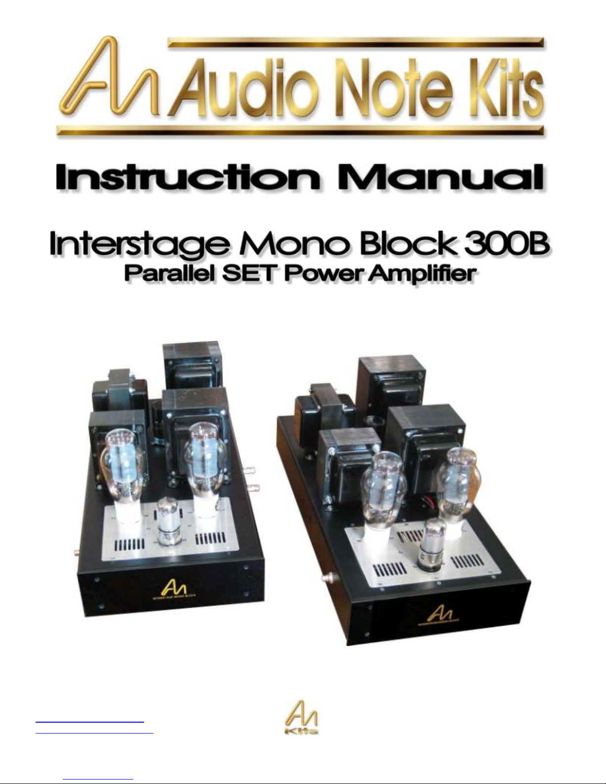
Thank you for choosing to purchase the new version Interstage Mono Blocks from AudioNoteKits Ltd.
Circuit Description
The model is the 300B Parallel version which provides approx 20W of single ended power with zero feedback – The
design is unique in that is uses a 1:1 interstage transformer between the driver stage and the output stage – see below for
a brief circuit description:
These amps are fronted by a 6SH7, connected as a triode, which may seem a little unusual, but apart from the 6SH7 and
the similar, but in a smaller package 6AU6 both being good sounding valves, and the fact that they are available at
reasonable prices there are good technical reasons for using it. The idea with these amps is to use an interstage
transformer, and only ONE amplifying stage before the output valves. This makes for an incredibly direct route, and the
amps sound better for it. Really, listening to such an amp is a revelation, there is only one gain stage, and there are no
coupling capacitors. The underlying coloration which coupling caps of all sorts produce is absent, and there is a far
greater sense of immediacy and dynamics. If you can imagine, the effect of the bifilar interstage is to knit together the
anode circuit of the driver valve and the grid circuit of output valve, what happens in one happens in the other.
Page 4
Copyright © 2010 AudioNote Kits
www.AudioNoteKits.com
audionotekits@rogers.com
Page 4
I explained in the interstage transformer article about the virtues of transformer coupling to the output valves, and here the
bifilar interstage transformer is used to full advantage. The extremely high impedance AC load to the 6SH7 means that
you get more or less the full gain of the valve, and the loadline is horizontal, which means because the 6SH7 is so linear
the distortion produced by the driver stage is very low, and predominantly even order. It’s an innate characteristi c that a
good triode has a constant mu over a wide range of operating conditions, therefore, as has been known for a long time, if
a triode is run in constant current mode (either by active load, or by transformer or choke loading) then the valve is as
linear as it can be. The secondary side of the transformer provides a low impedance path to ground for grid current.
A triode-coupled 6SH7 has a mu of 40 odd and an anode impedance below 10K, also it’s nicely linear, both as a triode
and as a pentode. The high gain, and low impedance means that the input sensitivity of the amp with only one stage, and
with a pair of 300Bs is still reasonable, if we were to look at using a 6J5 say, the gain is less than half and you start
needing serious volts to drive the thing, also the 6J5’s anode impedance is significantly higher and that would limit
bandwidth due to loading by the transformer and by the 300Bs. There is some kind of phobia, caused by a lack of
understanding about triode connecting pentodes, it’s really a case of choosing the right valve, and then using it in the right
way to get good sound.
There are some of the old telephone triodes out there, such as the 417A and 437A, but these are pretty scarce, and by all
means if you are up to it you can experiment and modify and try replacing the 6SH7 but if you melt your Western 300Bs
don’t call Brian!
Andy Grove - Audio Note design engineer
Page 5
Copyright © 2010 AudioNote Kits
www.AudioNoteKits.com
audionotekits@rogers.com
Page 5
Section 2: Mechanical Section
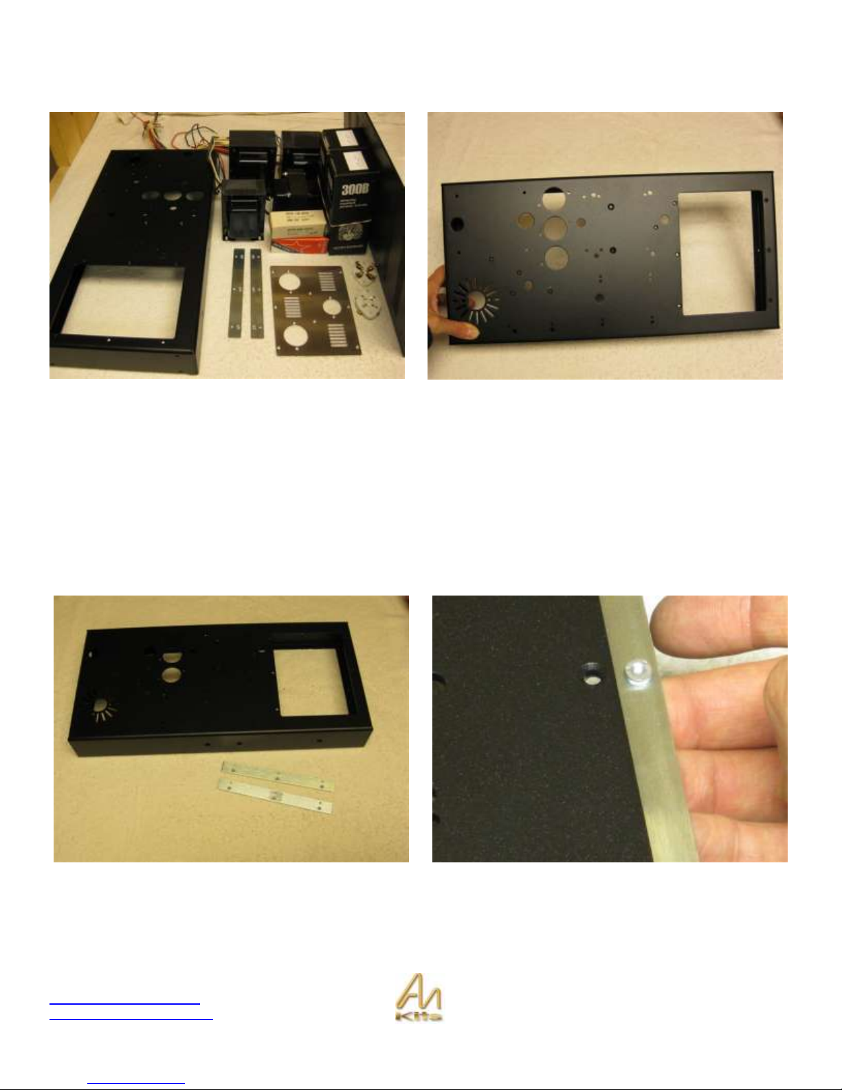
The first part of this manual will be the mechanical installation that is required – once that is completed we will proceed
with the wiring part!
First of all we use Metric Hardware in the kit – M3 and M4 metric – an M4 screw is similar to a #8 in the imperial system
and an M3 is between a #4 & #6 – so the M4 is the bigger of the two – we will also be using flat and pan head screws –
the flat or countersunk screws are very hand when we need a flat surface for a transformer to sit on the screw for
example! Ok lets get started!
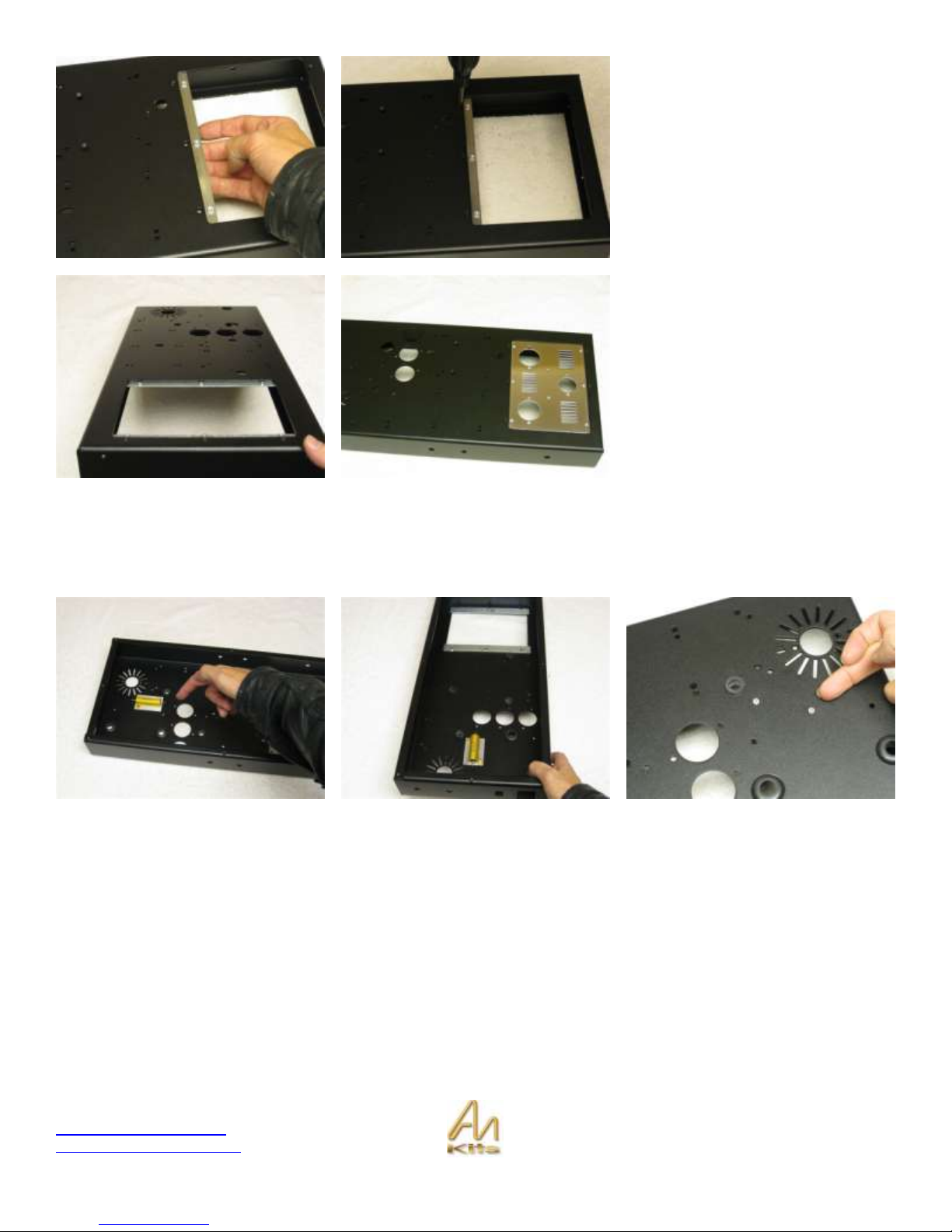
Tang Strip Installation
Let’s start by installing the two “Tang Strips” – these are used to support the front insert plate that we will be installing later
on.
Page 6
Copyright © 2010 AudioNote Kits
www.AudioNoteKits.com
audionotekits@rogers.com
Page 6
Install the tang strip as shown with the
PEMS (little threaded standoffs) facing
up to the sky.
Now use the black or stainless M3
10mm screws and m3 nuts to secure
the tang strips to the chassis.
You can position the front insert plate
in the chassis just to see how it fits but
we will not be securing it in place now
– we will be building on the front insert
plate and installing the completed
section into the mono block later on!
150R Mill Resistor Installation
Our next step is to install the 150 ohm Mills Power Resistor – this resistor is installed against the chassis – use the 2 x M3
countersunk 10mm screws and M3 nuts to secure into position
Page 7
Copyright © 2010 AudioNote Kits
www.AudioNoteKits.com
audionotekits@rogers.com
Page 7
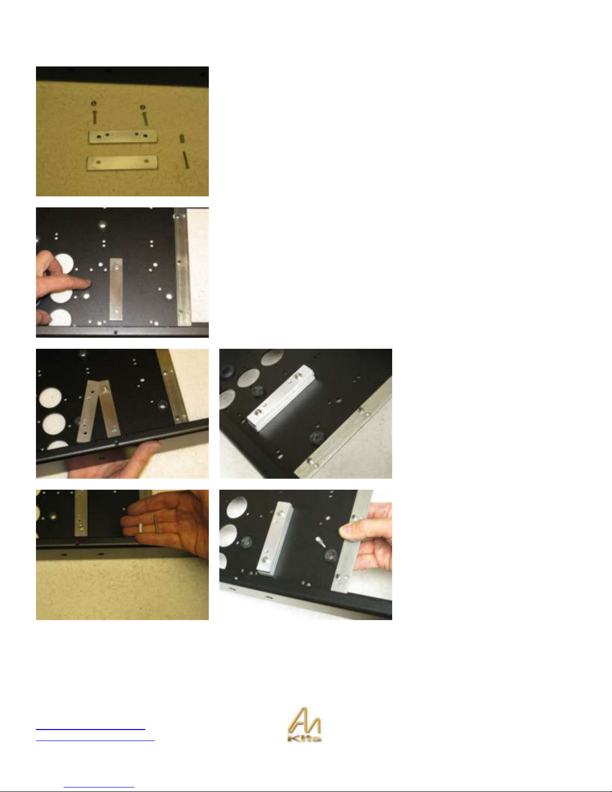
Heat Sink Installation
Our next task is to install the heat sink against the chassis which will be used by
the Filament Section of the Monoblock. Basically the 300B tubes receive a 5V
DC filament voltage via a regulator that needs to be heat sunk in order for it to
operate properly.
We will be installing two bars against the chassis.
Here the first bar is placed against the chassis.
Note this is the bar with just two holes in it .
The second bar that is placed on top.
Use the M4 countersunk screws
provided and thread them through the
front of the chassis.
Place the second heat sink with the 4
holes on top with the countersunk heat
sink holes facing up!
Tighten with the M4 nuts.
Now take the M3 25mm screw and the
M3 spacer and install such that the
spacer secures the screw into position
(see next illustrations also).
Page 8
Copyright © 2010 AudioNote Kits
www.AudioNoteKits.com
audionotekits@rogers.com
Page 8
The idea is that the filament board will
eventually sit up on the screw and
align with the heatsink!
Ok good work so far!
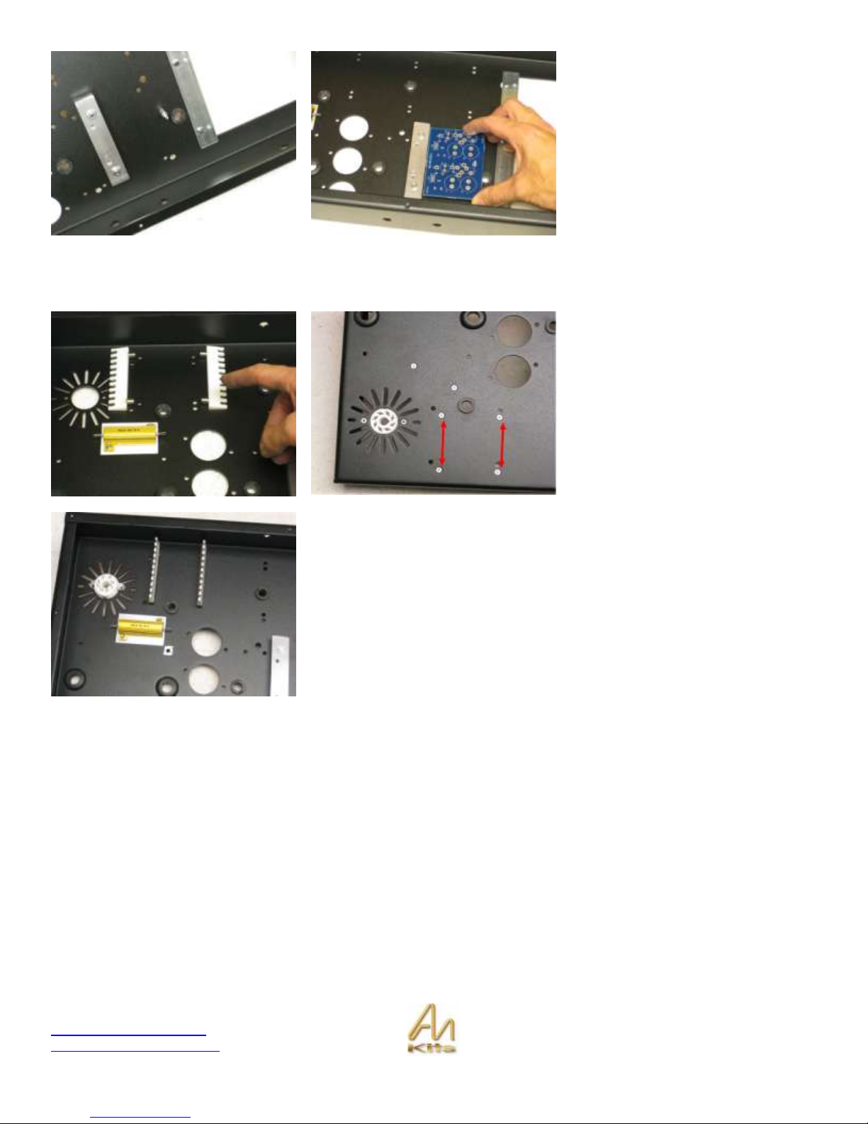
Ceramic Hardware post installation
Now we will install the ceramic posts
for the power supply hardwiring – they
use M3 countersunk screws which go
through the top of the chassis and
secure the ceramic posts on the
underside of the chassis.
The first picture simply shows the
posts laying next to the holes they will
be inserted into.
Here you can see the hardwire posts now installed in the chassis.
Page 9
Copyright © 2010 AudioNote Kits
www.AudioNoteKits.com
audionotekits@rogers.com
Page 9
8 Pin valve base installation – rectifier location
Now we will install the 8 pin valve base into the rear hole – the only trick is that the notch in valve base faces towards the
front of the chassis.
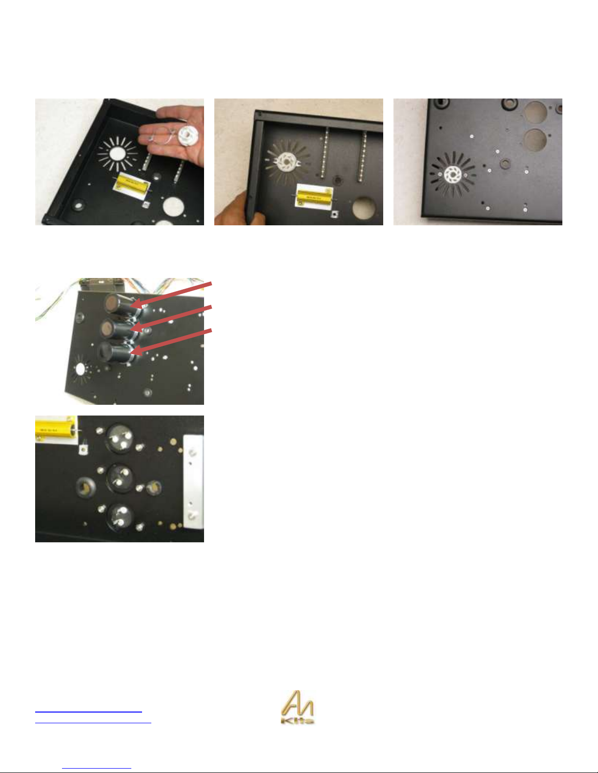
Installation of the three Power Supply Caps
250uf 500v
250uf 500v
100+100uf
Install the three caps into position.
The 35mm clamps are a bit tight but you should be able to
secure the caps into position as shown.
Use the M4 screws to secure into position.
Here below you can see the caps from underside of chassis.
Page 10
Copyright © 2010 AudioNote Kits
www.AudioNoteKits.com
audionotekits@rogers.com
Page 10
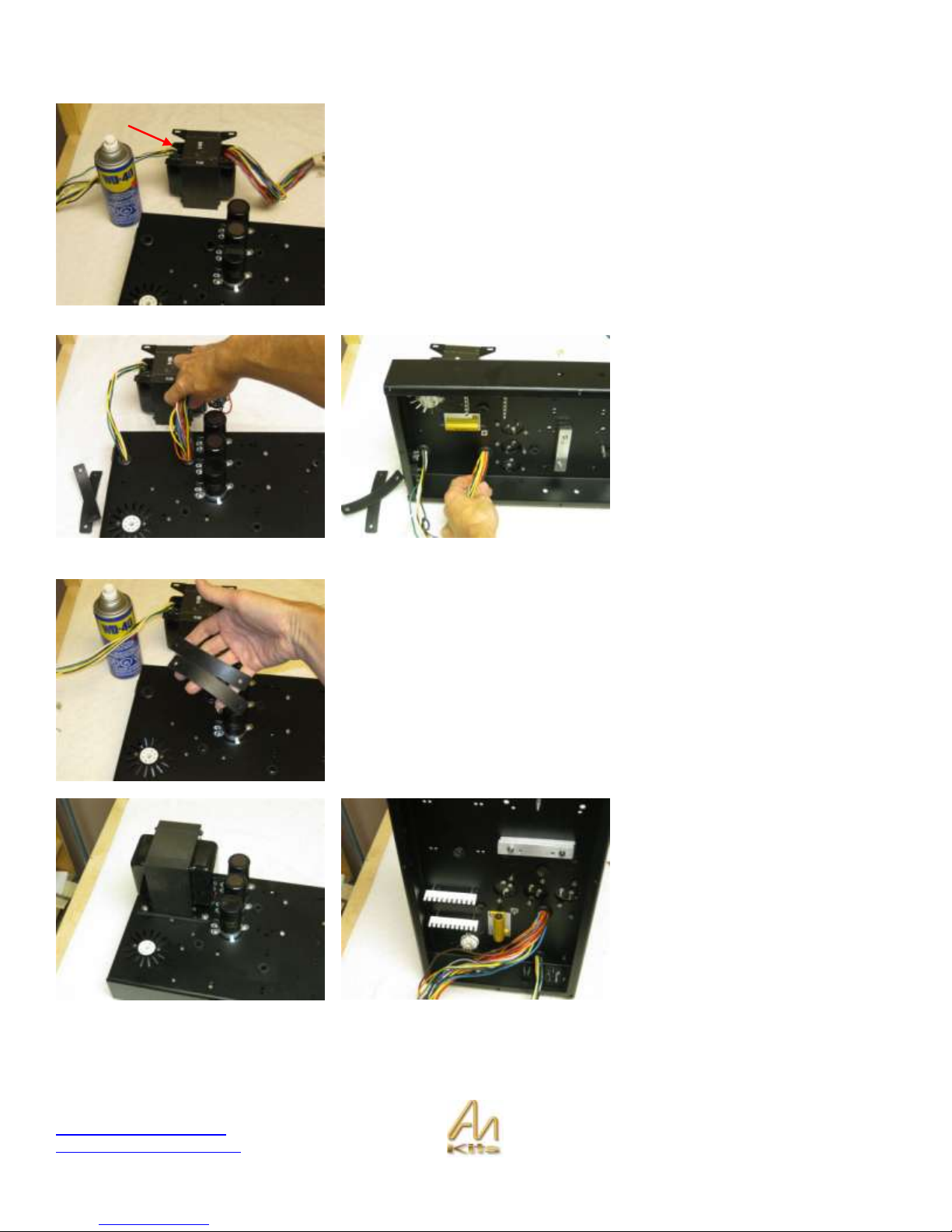
Installing the Mains transformer
We are going to install the T-199 Mains transformer now into position.
I suggest you lay the transformer upside down beside the chassis in the format
shown.
The Mains transformer has a primary side (0 110 120 etc.) and a secondary
(400 300 0 300 400 etc).
The Primary is the side with less wires - these wires are connected to the IEC
or AC inlet socket – so let’s position the transformer so that it the primaries are
situated at the back of the chassis.
The primaries for the Mains
transformer can be threaded through
the grommet hole quite easily but the
secondaries will need a little help – we
suggest you give the secondary wires
a light spray with the WD40 so that
they can slide through the grommet
hole a little easier.
Continue feeding the wires through while
the mains transformer lies on its side as
shown.
Now install the rubber strips into position over the holes so that the transformer
can sit on top of these and isolate from the chassis and secure the mains
transformer in place.
Once all the wires are fed through you can use a cloth to wipe off any excess
WD40 spray.
Here you can see the completed
Mains transformer installation.
Primary Side
Page 11
Copyright © 2010 AudioNote Kits
www.AudioNoteKits.com
audionotekits@rogers.com
Page 11
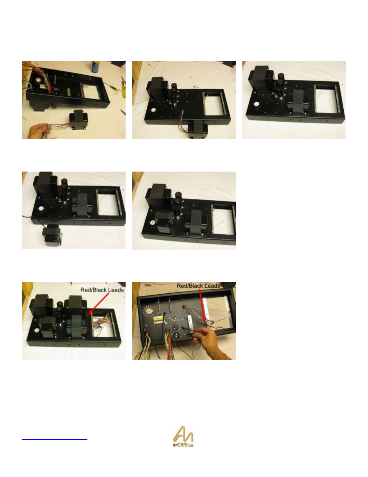
Installing the Interstage Transformer
Lets install the Interstage transformer – this is the transformer shown below with the 4 colored wires on it. Use M4 screws
and washers to install. The choke, which is similar in size, just has two black wires.
Installing the Choke
Install the CHOKE in the same
manner.
Installing the Output Transformer
The Red/Black pair go through the
hole nearest the front of the chassis.
The output wires (group of three) want
to be closest to the capacitors.
Page 12

Copyright © 2010 AudioNote Kits
www.AudioNoteKits.com
audionotekits@rogers.com
Page 12
Twisting the Wires
The underneath view of the chassis with all the transformers now installed!
The next step is to twist the same colored wires together on the Mains
Transformer for the upcoming wiring jobs!
Page 13
Copyright © 2010 AudioNote Kits
www.AudioNoteKits.com
audionotekits@rogers.com
Page 13
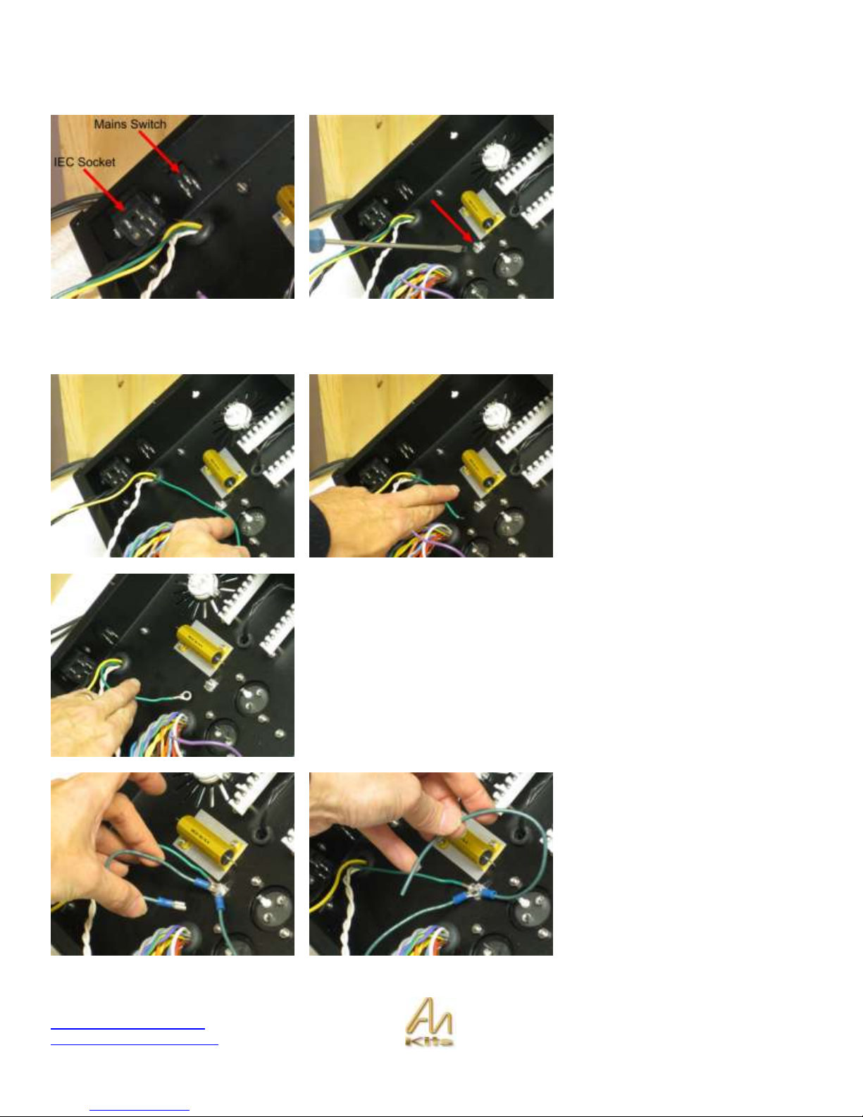
Section 3: IEC Section and Chassis Ground
The first picture shows the IEC socket
installed in the back of the unit with the
2 x M3 10mm csk screws, along with
the mains switch, which simply pushes
through the hole. Install these as
shown.
The second picture shows the Chassis
Ground screw which is one of the
Mains transformer screws.
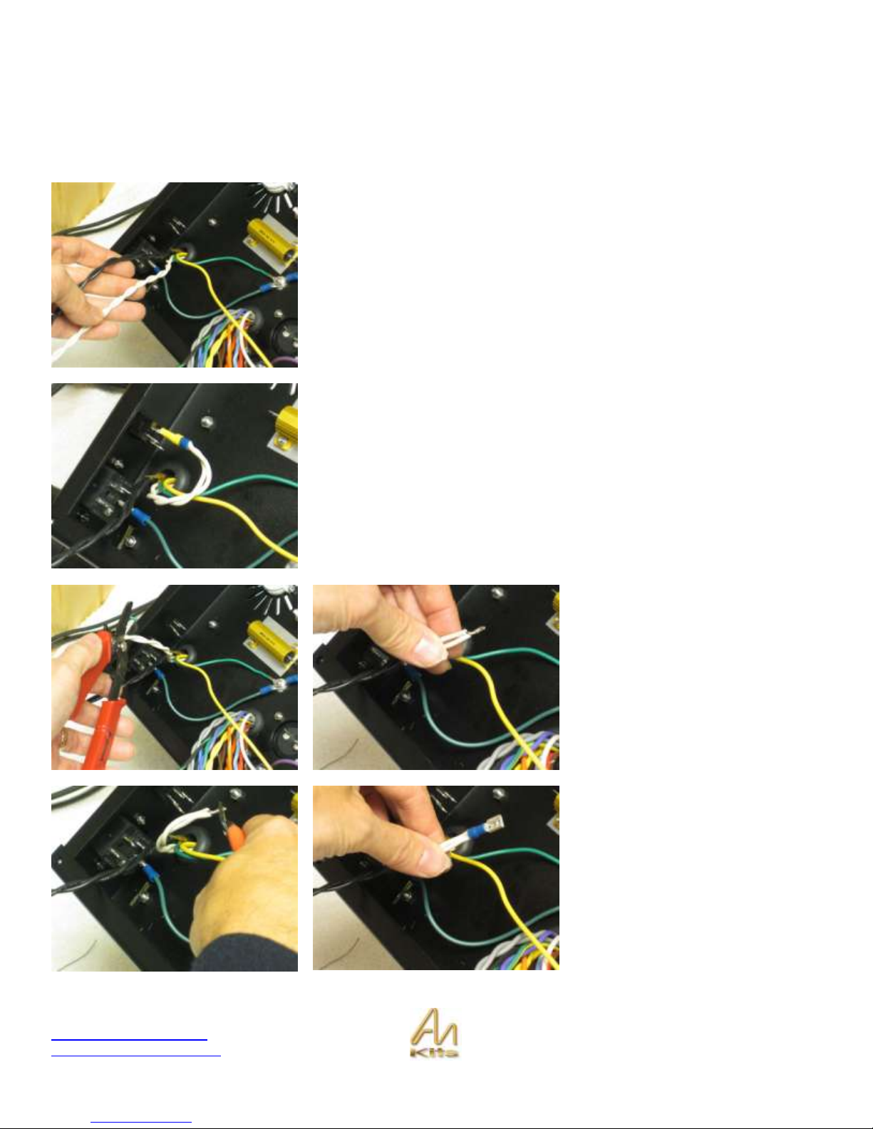
Chassis Ground Connections
Our first task is to take the green wire
from the Mains Primary and we are
going to connect it to the chassis
ground point.
Extend the wire past the chassis
ground point – then strip it and TIN the
wire (tinning is the process of adding
solder to a bare stranded wire so that
it can be easily connected to another
solder point).
Add the Ground Lug to the tinned wire and then solder the ground lug onto the
wire.
Since you have unhooked the nut on the chassis ground point we are going to
add two more prepared cables from the IEC bag to this chassis ground point...
Add in the wire with the GND lug and
crimp on it as well as the green wire
with just the GND lug on it.
Page 14
Copyright © 2010 AudioNote Kits
www.AudioNoteKits.com
audionotekits@rogers.com
Page 14
Now you can install the green wire
with GND lug and crimp on to the GND
post of the IEC socket which is the one
on the bottom of the IEC.
The third wire will be used later for the
power supply ground.
Gently tighten the nut – we may be
moving the wires a little so no need to
tighten too much!
IEC Wiring
In this section we will be hooking up the IEC section – the following example is for 120V operation – refer to the
appendix for wiring for all the world voltages.
Page 15
Copyright © 2010 AudioNote Kits
www.AudioNoteKits.com
audionotekits@rogers.com
Page 15
We have provided a number of pre-made cables & parts for this section to make it nice and clean
1. 2 CRIMPS
2. Heatshrink
3. IEC GND >> CHASSIS GND cable (already used)
4. Blue/Brown Twisted CRIMPED cable
For 120 V operation take the twisted white and twisted black pairs of wires.
Let’s start with the white pair – we will be cutting this wire, stripping the ends off,
twisting the two ends together, tinning, adding a crimp to the end and soldering
the wire on to the crimp, then installing the heat shrink!
It is a good idea to read a few pages before beginning so you understand the
process.
This is what we will end up when we have completed the white wires.
Let’s start by trimming the white wires
– leave some extra length in case you
mess up and need to start again – I
would leave about 5 inches of twisted
white wire at least.
Here we have cut the wires, twisted
together and then TINNED them (i.e.
added solder to the exposed wire).
You may want to trim the tinned wire
to the desired length and then place
the crimp over the tinned bare wire – if
it does not fit then try smoothing out
the tinned wire with soldering iron.
Then add some solder in the hole
showing – use a fine tipped soldering
iron – make sure the solder “Takes”
such that the solder is shiny and the
wire has accepted the solder!
Page 16
Copyright © 2010 AudioNote Kits
www.AudioNoteKits.com
audionotekits@rogers.com
Page 16
Then add the prepared heat shrink on
the end.
If you do not have a heat gun you can
run your soldering iron over the heat
shrink quickly and it will shrink – clean
off any excess solder off your
soldering iron if you use this method.
Once that is complete you can insert
the crimp on to the bottom of the
rocker switch. Make sure you wait for
the crimp to have cooled down a little
after putting on the heat shrink.
The second picture here also shows
black wires now installed onto the
rocker switch. You can do this now.
Now take the prepared twisted cable
and install on the IEC as per the
picture to the left.
This completes the IEC section – well
done!
Page 17
Copyright © 2010 AudioNote Kits
www.AudioNoteKits.com
audionotekits@rogers.com
Page 17
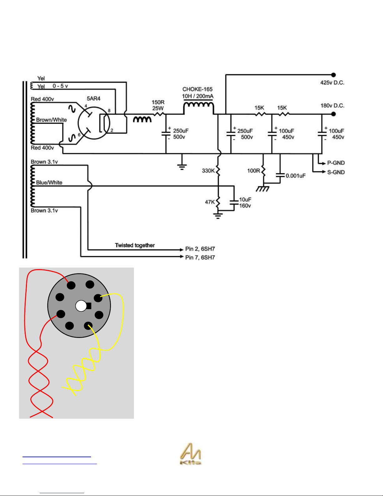
Section 4: Power Supply Wiring
In this section, we are going to start wiring the power supply. You should follow the following diagram as you progress
through the section. It may be a good idea to use a highlight pen on the diagram as you progress.
Rectifier Wiring – 8 pin tube valve base
We are now going to wire up some of the Mains secondaries to the Rectifier
Valve base at the back of the chassis.
In order for the tube to work at all we have to provide a filament voltage to the
tube – in the case of the 5AR4 the filament voltage is 5V AC.
If you look on your transformer wiring chart you will see that the yellow
secondaries are the 5V AC – so we will connect these to pins 2 & 8 of the 8 pin
rectifier base.
You will see a notch on the 8 pin valve base and the notch is between pins 1 & 8
. after the notch counting clock wise starting from one from the side of the base
as shown in the picture opposite we can see where pins 2 & 8 are.
1
4
5 6 7
2
3
8
Page 18

Copyright © 2010 AudioNote Kits
www.AudioNoteKits.com
audionotekits@rogers.com
Page 18
Take the yellow twisted wire and cut to
an appropriate length like in the
photographs – leave a little extra –
now cut the wires, strip the insulation
off the end and I suggest tinning the
wire and then trimming again – then
position the wire into the correct valve
base pin – then apply solder – you will
see that the tinned wire will take the
solder easily – I suggest you use the
bottom holes of the valve base.
The rectifier tube also takes the high voltage AC which in this case is 400v AC
on each wire (in opposite phase) and we apply to pin 4 & 6.
Here you can see the red wires hooked up to pins 4 & 6.
That completes the AC wiring for the Rectifier tube.
Power Supply Chassis Ground
Take the third wire that you previously connected to chassis ground – we are
going to connect it to the bottom of the LEFT hand ceramic power supply post.
Strip the wire and it is a good idea to tin the wire before inserting it into the first
position by just pushing a little with your soldering iron you will find that the
tinned wire will quickly adhere to the post.
Now take the Blue/White wire from the Mains secondary and this will go into
position 2 on the LEFT hand side ceramic post.
If you check out the Mains transformer chart you will see that the BLUE/White
wire is the center tap for the 6.3V AC 1A that we will be using for the 6SH7 tube
filament later on – We will be raising the filament supply for this tube by 40V –
see overall technical description of the amplifier.
Page 19

Copyright © 2010 AudioNote Kits
www.AudioNoteKits.com
audionotekits@rogers.com
Page 19
Installation of the 100R resistor into
the first position – this resistor is
between power supply ground and
chassis ground.
Now add the .001uf capacitor across
this resistor and leave the leg on the
right side so that we can bend it up
and have it connect to position 2.
Now add the 47K resistor in position 2 and leave the extra as we will bending on
the LEFT side this time – see next part.
You can install the 330k resistor now into position and connect the LEFT side
between the 47K & the 330K resistors.
Now on the top position on the ceramic hardwire post we want to add the pair of
15K resistors and they are connected to each other on the LEFT hand side –
see graphic.
Page 20

Copyright © 2010 AudioNote Kits
www.AudioNoteKits.com
audionotekits@rogers.com
Page 20
Now let’s wire in the CHOKE.
The choke has two wires – both black and either can be used as input or output
– a choke is basically one long piece of wire wrapped around a core in order to
slow down any AC movement – they are used in power supplies smooth out the
DC that is created by the rectifier tube. Start by taking the CHOKE Wires – we
will be connecting one end to the ceramic posts in position 3 - RIGHT Side (the
other end will connect to the 150R power resistor later on that is connected to
the chassis). Check out the schematic of the power supply and you will see
these connections.
Trim the choke wire (leave a little extra) and tin it and then position into the
ceramic post 3-LEFT – at the same time cut a length of RED wire and also TIN
and insert into positions 3 LEFT and 9 Left – with both wires installed in 3 LEFT
you can then add solder and make a single solder connection at 3 LEFT.
The graphic opposite shows a map
of the wiring for the Power supply up
to this point.
Refer to the appendix of the
complete wiring progression from
this point forward.
15K
15K
330K
47K
100R
+
+
+
+
Interstage
CHASSIS GND
S-GND
2 1 3
4
5 6 7
8
100+100
250uf
250uf
Mains
Transformer
secondary
150R
.001
Page 21

Copyright © 2010 AudioNote Kits
www.AudioNoteKits.com
audionotekits@rogers.com
Page 21
Now let’s add the first power supply connection of the red wire from the 15K
resistor to the + of the 100+100uf capacitor (see red wire at the right of this
picture).
Before we continue with wiring up
the power supply capacitors let’s
make the connections to the 150R
power resistor mounted on the
chassis.
You will need to connect from pin 8
of the rectifier tube base to the input
of the 150R resistor.
2010 Interstage Mono Block Kit – AudioNoteKits
15K
15K
330K
47K
100R
+
+ + +
Interstage
CHASSIS GND
S-GND
2
1
3
4
5
6
7
8
100+10
0
250uf
250uf
Mains
Transformer
secondary
150R
.00
1
Page 22

Copyright © 2010 AudioNote Kits
www.AudioNoteKits.com
audionotekits@rogers.com
Page 22
Then connect the output of the
resistor to the power supply
capacitor as shown below and also
connect the other wire of the
CHOKE.
Connect the Brown/white wire from
the Mains secondary to the Ground
on the Power supply – this is the
center tap.
2010 Interstage Mono Block Kit – AudioNoteKits
15K
15K
330K
47K
100R
+
+
+
+
Interstage
CHASSIS GND
S-GND
2
1 3 4
5
6 7 8
100+10
0
250uf
250uf
Mains
Transformer
secondary
150R
.001
Page 23

Copyright © 2010 AudioNote Kits
www.AudioNoteKits.com
audionotekits@rogers.com
Page 23
At this stage you can complete the rest of the power supply wiring by following the graphic below:
So basically examine the hi resolution pictures along with the graphic and the schematic to double check your work – take
your time and make your connections.
1. Connect the three grounds on the power supply caps together and also to the Ground point on RIGHT 1 & 2
2. Connect the remaining additional red wires with the same connections shown above in the graphic
2010 Interstage Mono Block Kit – AudioNoteKits
15K
15K
330K
47K
100R
+
+
+
+
Interstage
CHASSIS GND
S-GND
2
1 3 4
5 6 7
8
100+10
0
250uf
250uf
Mains
Transformer
secondary
150R
.00
1
Power Supply Capacitors
Page 24

Copyright © 2010 AudioNote Kits
www.AudioNoteKits.com
audionotekits@rogers.com
Page 24
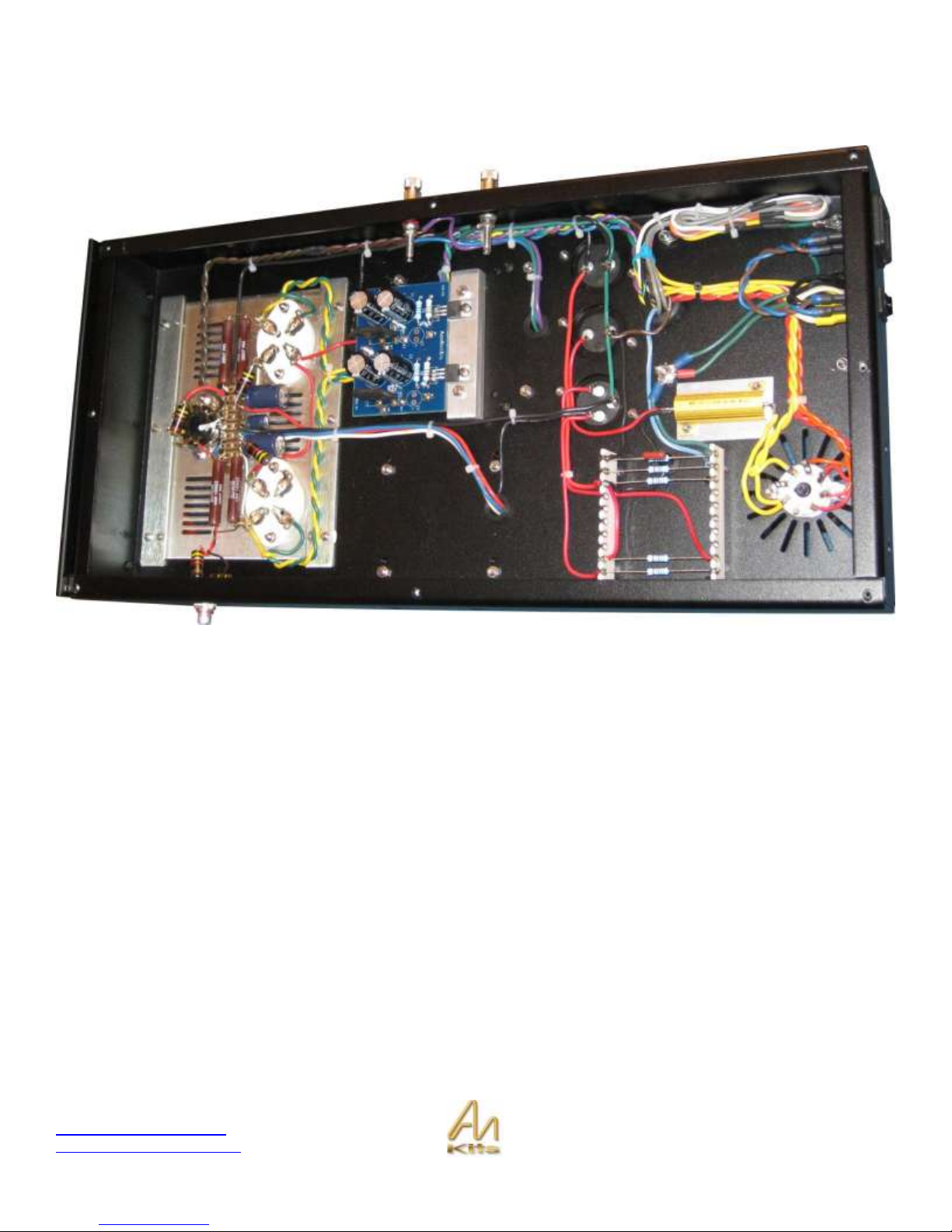
The picture above shows all the connections up to this point
If you would like you can follow the schematic and make sure all the connections make sense.
Page 25

Copyright © 2010 AudioNote Kits
www.AudioNoteKits.com
audionotekits@rogers.com
Page 25
Section 5: Filament Supply Section
In this section we are going to build the Filament Supply Board – this PCB basically takes in the AC voltage from the
secondary’s (7vAC) and converts it to 5V DC for the 300B valve bases.
4
CAPACITOR
4700uF 16V
2
Bridge Rectifier
KBU6J
2
LM1084 Adjustable V Regulator
LM1084 ADJ
2
110R
R2,R4
300B Filament 5V
2
330R
R1,R3
The Electrolytic capacitors are installed with the STRIPE on the negative side of
the PCB.
You will note on the PCB you can see a + sign denoting the positive side of the
electrolytic capacitor – The side of the capacitor with the strip denotes the
negative side of the cap –
The capacitors should be installed as shown in the photo opposite.
Page 26

Copyright © 2010 AudioNote Kits
www.AudioNoteKits.com
audionotekits@rogers.com
Page 26
Now install the 2 bridge rectifiers
(KBU6J).
You will note on the PCB that the
locations for the Bridge Rectifiers BR1
& BR2 have a + designation at the
bottom. Then if you look at the bridge
rectifier itself you will notice they have
a corner cut off – this is the + side.
Once the rectifiers are installed then we can install the resistors into position.
2
110R
R2, R4
300B Filament 5v
2
330R
R1, R3
The LM1084 regulator that fixes a DC output voltage is configured by a ratio of
resistors – when the ratio is 3:1 then the output voltage is 5V which is what we
need for the 300B – So install the 330R resistors into position R1 and R3 - then
install the 110R resistors into position R2 & R4.
LM1084 regulator install
This regulator will be installed so that it is screwed into the heat sink that you
have already mounted in the chassis of the mono block.
Even though the heat sink is mounted on the chassis it is actually electrically
isolated such that the 5V DC can float at about 70V on the 300B tube – we do
this by using an insulation kit that we will discuss in a minute – for now let’s get
the correct mechanical install of the regulators into the filament board by
measuring their distance on the heatsink.
Align the regulator over the screw hole
in the heat sink and then using pliers
bend the legs of the regulator at right
angles so that they will fit into the PCB
as shown.
A good trick is to actually use the M3
8mm screw provided and screw the
regulator into position and then solder
the legs of the regulator to the PCB
from the top side.
Page 27

Copyright © 2010 AudioNote Kits
www.AudioNoteKits.com
audionotekits@rogers.com
Page 27
Remove the screw when you are finished as we have to add some more wiring
to the filament board along with the insulation kit before we bolt into position.
With the filament board now prepared let’s get the Mains secondary wires that we will be connecting to it to provide the
AC voltage input – you should check your Mains wiring diagram and view the colored wire required here - You will need
the Blue & Black wire that is a twisted pair along with the violet & Green/Yellow wire – these two twisted pairs will connect
underneath the filament board into the following positions:
Bring the filament wires along the edge of the chassis below the power supply caps and then turn at right angles up to the
underside of the filament board – now take the first twisted pair (Blue & Black) and connect to W5 and W7 – I suggest you
strip the wire and tin – then cut the tinned wire to a short length as it will be difficult to trip on the top side of the board –
then solder from the underside of the board.
Then repeat for the Violet and Green/Yellow pair into W6 and W8 on the filament board.
Once that is complete we will now connect the provided twisted red/black filament wire into W1 (red) and W3 (Black)
and then another length of red/black filament wire into W2 (red) and W4 (Black).
We are not going to secure the filament board into position at this time as we will be adding some mains wires to this
section and we will need to get under the board – so let’s move on to the next step which is the front insert plate!
Page 28

Copyright © 2010 AudioNote Kits
www.AudioNoteKits.com
audionotekits@rogers.com
Page 28
Section 6: Installing the Front Insert Plate
There are a number of ways to proceed on the mono block build and what we outline in the manual is a very good guide
to follow – if you feel that you have some very good experience and would like to make your own changes feel free to do
so and just check your work with the schematics provided. For example, you could build the insert plate outside of the
mono block and then once its complete you can install and then connect up the external wiring – we are going to suggest
in this case to make the mechanical installation of the front insert plate and then we will complete the mono block wiring
from inside.
Here is the front insert plate for the
300B parallel triode configuration.
Notice that the top side of the front
insert plate has the countersunk
screws holes on it – You will insert the
countersunk screws on this side.
Go ahead and install the 4 pin valve base plate.
You will notice that the valve base for the 300B has 2 small holes and 2 bigger
holes – the bigger holes are for the filament voltages – make sure these bigger
holes are positioned closer to the side of the chassis.
Use a m3 Washer on the underside of the chassis along with the M3 but – Use
the M3 16mm screw for the large 4 pin valve bases.
For the 8 pin valve base install such that the notch is on the right side.
Page 29

Copyright © 2010 AudioNote Kits
www.AudioNoteKits.com
audionotekits@rogers.com
Page 29
Now let’s install the Tag strip.
You can see the hardware that you will use to install the tag strip.
Use the countersunk screw on the top of the chassis to secure the hex spacer.
Here is a view of the tag strip installed on the insert plate.
Page 30

Copyright © 2010 AudioNote Kits
www.AudioNoteKits.com
audionotekits@rogers.com
Page 30
Section 7: Mains secondary to Filament Section Wiring
We are now going to complete some inter-wiring to the Filament Board by taking the two twisted pairs of wires from the
Mains secondary and connecting these to the FILAMENT board.
Take the blue wire and black wire and twist them together from the Mains secondary and lay them along the edge of the
chassis – do the same thing with the Violet and Green/Yellow wires – Now route these wires along the edge of the
chassis and then bend them at right angles to route over the filament board.
Blue connects to W8 filament board
Black connects to W6 filament board
Violet connects to W7 filament board
Green/Yellow connects to W5 filament board
We suggest that you trim the wires and then TIN the ends – cut them quite short as they are difficult to cut from the top
side of the board since the components are in position – connect the wires from the underside of the board and I would
suggest soldering from the underside of the board – with the wires tinned they should be quite easy to solder.
Once all the AC input wires are soldered into position then we need to add some more wires – these will be the DC output
wires – take the red/black PTFE twisted wire and cut two pieces of approx 20”. Then again trim the ends of one end of the
red/black twisted and solder from the underneath of the board – these wires will be exiting from the opposite side of the
board from where the heat sink is – connect:
W2 filament board to Red
W4 Filament board to Black
Next twisted pair
W1 filament board to Red
W3 filament board to Black
We will be connecting the wires later to the front insert plate section.
Now let’s secure the filament board into position.
Position the wired board over the holes in the heatsink –
Now place the mica piece on the heatsink under the
regulator – use an M3 8mm screw and the plastic insert on
the top of regulator.
Here you can see how the regulator is positioned on the
heatsink – now gently tighten the screw so that a good
connection is made – do not over tighten or squeeze the
daylights out of the screw.
Repeat for the second regulator.
Page 31
Copyright © 2010 AudioNote Kits
www.AudioNoteKits.com
audionotekits@rogers.com
Page 31
At this point it is worthwhile to do a little test with an ohm meter to make sure
that the regulators are indeed isolated from the heatsink via the mica – The
reason for this is as follows:
The amplifier requires that the 5V DC supplied to the 300B tube is “floating” this
allows the cathode of the 300B to sit at 60V approx and allows current to flow
correctly through the 300B tube – this is basically considered biasing the
amplifier tubes correctly – if the regulator is actually touching the heatsink which
is connected to the chassis and is at GROUND potential then the 300B cathode
will not be able to float at 60V but instead be brought down to ground potential
resulting in fairly catastrophic consequences for the amplifier involving smoke
and blown fuses!
We suggest you perform the following test at this point with your own meter:
Use your ohm meter to verify that the regulator pins and the metal part of the
regulator are NOT connected to the heat sink. In this picture my meter is reading
1 which means Infinite resistance which is like an OPEN circuit or NOT
connected – some meters will say OL which means the same thing.
If my meter read 3 ohms for example then this would be a problem which tells
me that there is a connection between the heat sink and the regulator – if you
are getting a low ohm reading then you will want to re seat the regulator – make
sure that no part of it is touching the heat sink!
With the filament section installed correctly now lets get back to the Front Insert Plate!
Page 32

Copyright © 2010 AudioNote Kits
www.AudioNoteKits.com
audionotekits@rogers.com
Page 32
Section 8: Installing the Front Insert Plate
Let’s install the front insert plate in the chassis by securing
into position with the M3 screws – no nuts required as the
tang strips have PEMS on them with threads for screw.
Ok well done to this point – we are now going to proceed
with some wiring.
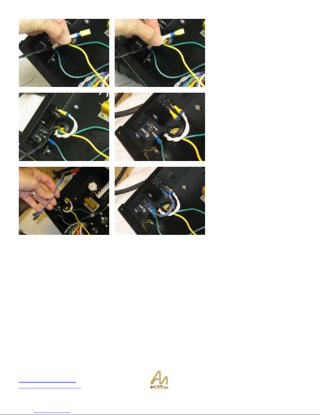
The first thing we are going to do is connect the AC filament voltage from the
Mains secondary – Get the twisted brown wire from the Mains secondary and
lay it along the “bottom” edge of the chassis – you will need to extend this with
the provided twisted brown wire.
To extend the wire I suggest you strip the wire and then add some heat shrink –
then twist the joined wire together and tin it – let cool and then slide the heat
shrink over it.
NOTE – the new version T-198 will have an extended Brown twisted pair so you
will not need to extend.
Once the brown wires have been extended then lay the wire along the bottom
edge of the chassis and curl up to the 8 pin valve base – connect to pins 2 & 7
of the 8 pin valve base.
See the following graphic showing filament wiring.
Page 33

Copyright © 2010 AudioNote Kits
www.AudioNoteKits.com
audionotekits@rogers.com
Page 33
The above graphic shows some connections that we will now make between the front insert plate and the power supply:
1. Filament supply to the 6SH7 tube – basically you will need to extend the twisted brown wires from the Mains
secondary’s and position them along the edge of the chassis as shown and then connect to the filament pins on
the 6SH7 pins 2 & 7.
You just completed the brown wire filament - now let’s add to ground wires – black
2. Connect a Black wire from the GND pin on the bottom 250uf capacitor on the power supply along the edge of the
chassis and connect to the position H on the tag strip – this is called the P-GND or power ground and you can
indentify it on the schematic.
3. Then connect another ground wire called the S-GND or signal ground between the Negative on the 100+100 cap
connected to LEFT hand side of position D.
Page 34

Copyright © 2010 AudioNote Kits
www.AudioNoteKits.com
audionotekits@rogers.com
Page 34
Front Insert Panel Wiring
For the front insert wiring we have some nice graphics showing you all the connections that need to be made for this
section – We have labeled the tag strip with the letters A, B, C, D ,E ,F ,G and H and we have a little chart showing what
connections are to be made to each of these “tags”.
Here, you can see a completed version or what we
are aiming to accomplish – we will break down each
step one by one.
Ok lets start with the basics and add some wires to the tag strip – you may want to make some changes possibly to the
way that we suggest and that is fine – I would suggest that you read through this entire section and get a feel for what is
going on – check the schematic and feel free to make your own tweaks along the way or follow our instructions precisely!
Page 35

Copyright © 2010 AudioNote Kits
www.AudioNoteKits.com
audionotekits@rogers.com
Page 35
I suggest you refer to the Slides in the appendix which are each on a full page for added detail.
Start by adding the wires between A & H
and then another length of wire between C
& F – I suggest that you tin the wire after
you have cut it to length and insert through
the hole in the tag strip.
Install the 4 1K5 power resistors as
shown above – check out the pictures
– also refer to the hi resolution pictures
on the disk.
Take your time and bend the leads
accordingly – a little extra time here
will pay off – then make sure you have
a really nice solder joint.
Page 36

Copyright © 2010 AudioNote Kits
www.AudioNoteKits.com
audionotekits@rogers.com
Page 36
Add the three electrolytic capacitors and be
sure to orient the correct + and – sides to
the capacitors as per the diagram.
Connect a red wire from pin 2 to pin 2 of
each 300B.
Connect a black wire from B to pin 1 TOP
and G to pin 4 BOTTOM – HINT – solder
these from under the tag strip.
Page 37

Copyright © 2010 AudioNote Kits
www.AudioNoteKits.com
audionotekits@rogers.com
Page 37
Now you can connect up the input RCA –
Install the RCA and then you will need to
add the input resistors in the configuration
shown in the graphic – a 1K resistor
connects to pin 4 of the 6SH7 valve base –
while the 100K resistor connects between
the RCA input and GROUND and then also
connects to TAG-D.
Add a 100R resistor on the 6SH7 between
pins 6 & 8 – refer to your schematic to verify
the correct pins.
Add a short wire from pin3 of the 6SH7 to
TAG E.
Add the 1K grid resistors that go from the
tag strip to pin 3 of each 300B.
Add the 330R resistor ( cathode) from pin 3
of the 6SH7 to the TAG D.
Page 38

Copyright © 2010 AudioNote Kits
www.AudioNoteKits.com
audionotekits@rogers.com
Page 38
300B Filament Wiring
Now take the twisted black/red filament wire
from the DC Filament section (BLUE PCB)
and connect to the 300B as shown in the
graphic above – would be good idea to tin
the leads of the filament wire after you strip
it and install.
Interstage Transformer Wiring
Now we will connect the interstage
transformer leads into the front insert plate
section.
There are basically three wires from the
interstage - Blue, white (shown as dotted),
and red.
Check out the schematic to see the
functions of each wire that you will be
connecting up:
Blue Interstage wire connects to TAG A
White Interstage wire connects to TAG C
Red Interstage wire connects to pin 8 of
the 6SH7
Page 39

Copyright © 2010 AudioNote Kits
www.AudioNoteKits.com
audionotekits@rogers.com
Page 39
Finally connect the S-GND wire from the
Power supply section to TAG-D if not
already completed.
Front Insert Plate Wiring Chart check list
6SH7
Pin 1 – Not connected
Pin 2 – AC Brown Filament from Mains secondary
Pin 3 – 330R, Wire to TAG-E
Pin 4 – 1K resistor from RCA
Pin 5 – Not connected
Pin 6 – 100R resistor which connects to Pin 8
Pin 7 – AC Brown Filament from Mains Secondary
Pin 8 – 100R resistor which connects to Pin 6
TAG Strip
TAG –A – 1K5 , 220uf 100v NEGATIVE, TAG A-H connection, Blue Interstage wire
TAG – B – 220uf 100v POSITIVE, TOP 300B pin 1
TAG – C – 1K to pin 3 – 300B TOP, TAG C – F connect, White Interstage wire
TAG – D – 470uf 16v NEGATIVE, 330R to 6SH7 pin 3, black S-GND wire from PS
TAG – E – 470uf 16v POSITIVE, 6SH7 pin 3
TAG – F – 1K resistor to pin 3 300B BOTTOM, TAG F-C connect wire
TAG – G -220uf 100v POSITIVE, black wire to pin 4 300B Bottom
TAG – H – 1K5, 220uf 100v NEGATIVE, 1K5, P-GND wire to PS
Page 40

Copyright © 2010 AudioNote Kits
www.AudioNoteKits.com
audionotekits@rogers.com
Page 40
300B TOP
Pin 1 – RED Filament wire from DC filament Board
Pin 2 – Red wire to Pin 2 of Bottom 300B (HT)
Pin 3 – 1K resistor that connects to TAG C
Pin 4 – BLACK Filament wire from DC filament Board
300B BOTTOM
Pin 1 – BLACK Filament wire from DC filament Board
Pin 2 – Red wire to Pin 2 of TOP 300B (HT), red wire from O/P transformer PRIMARY
Pin 3 – 1K resistor that connects to TAG F
Pin 4 – RED Filament wire from DC filament Board
Page 41

Copyright © 2010 AudioNote Kits
www.AudioNoteKits.com
audionotekits@rogers.com
Page 41
Section 9: Final Connections
Take the Black wire from the output transformer primary and connect to the bottom 250uf capacitor – POSITIVE.
SPEAKER BINDING POST Connections
Above we have a graphical representation of the connections to the speaker posts on the side of the chassis – the IE core
output transformer has three colored wires on the secondary – Green is ground , Blue is 4 ohm tap and Purple is 8 ohm
tap. For 8 ohm speakers you can connect the purple wire to the Red speaker post and the green wire to the Black
speaker post. You will also connect a ground wire from the PS GND capacitors to the Black speaker post as shown above
+
+ + +
O/P TX
P - GND
Speaker
Bind
posts
4 ohm
8 ohm
Page 42

Copyright © 2010 AudioNote Kits
www.AudioNoteKits.com
audionotekits@rogers.com
Page 42
Section 10: Finishing Off and Testing
We have now completed the Mono Block and we are going to go through a process to power on and test the unit to make
sure it is working properly.
As you can see we have our amplifier along some of the tools that you will find useful
a. Variac (Optional but useful!)
b. Audio Test CD 1Khz
c. Schematics
d. Tubes 2 x 300B , 6SH7, 5AR4
e. Dummy Load 8-10ohm power resistor
f. Voltmeter / Ohm meter
With the mono block wired up it is time do to some checks to make sure that amplifier has been correctly wired – This is a
good time to take out an OHM meter and do some checks for connectivity and resistances – I would suggest taking the
Schematic of the front insert plate section and checking the resistance from the cathode of the tubes to ground etc.
The cathode is the point on the tube closest to ground and by measuring the voltage from the cathode to the ground we
can tell if a tube is operating – it’s also good to measure the resistance from cathode to ground - the cathode on the
300B’s is the pin where the 1K5 power resistors are connected.
The Voltmeter / Ohm meter is a very useful tool – a lot of successful debugging
and checking of an amplifier can be done with the power off and an OHM meter
where we can check for connectivity and resistance – this is a very powerful
checking tool – it is also a great way to learn about your amplifier.
For those who like to read schematics lets use an ohm meter to do some
preliminary checks – for example a good place to start is to measure resistance
to ground from some of the points in the circuit.
Page 43

Copyright © 2010 AudioNote Kits
www.AudioNoteKits.com
audionotekits@rogers.com
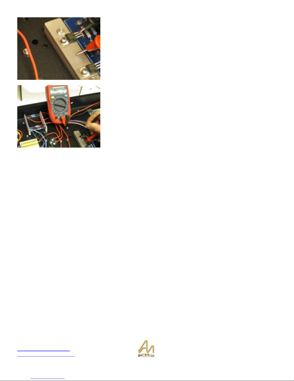
Page 43
A good place to start would be to
measure resistance – let’s do an easy
one and check the voltage across the
GOLD 150R resistor that is attached to
the chassis in the power supply
section.
Put a probe on each side of this
resistor and check the resistance and
you should see 150 ohms.
The red arrows on the picture opposite
show its location on the schematic.
This picture shows a probe on CHASSIS GND – this is the
universal ground point in the amplifier and is great for then
positioning the red probe somewhere else in the amplifier to
get an overall resistance reading.
TIP – the chassis is ground and you can actually put the
probe also in the little PEM hole on the bottom of the
chassis that secures the base plate – since its unpainted
inside you can make direct contact with the chassis here.
Another suggestion would be to use the ohm meter as a
connectivity tool and put one probe on chassis ground and
then check all the other grounds in the circuit to see that
there is zero ohms or close (a couple of ohms is OK)
between all the ground points.
Once the OHM checks and connectivity checks are done
then let’s move on to our first power up.
You can try installing the 2A fuse in
the IEC socket.
Remove the fuse holder from the IEC
socket and install the 2A fuse into
position – then re insert into the IEC
section..
Page 44

Copyright © 2010 AudioNote Kits
www.AudioNoteKits.com
audionotekits@rogers.com
Page 44
As a next step you could turn on the Amplifier with no tubes installed and then
we can check some filament voltages - we can also see if the fuse is going to
blow or not!
When the 1 is pressed down the amplifier is ON.
Let’s check the 5V DC on the filament pins of the 300B – these are the two FAT
pins on the 300B that are nearest the sides of the chassis (this is also true for
the other 300B).
Then check the AC filament on the 6SH7 tube – Put the meter on AC
measurement – we should have about 6.3V AC.
If all is well you can power down the amplifier and install JUST the 300B tubes
and the 6SH7 tube on the front insert plate – WE will not install the 5AR4
rectifier tube at this point.
QUICK TUBE LESSON - Just some basics on the tubes that we are using
300B – these two large tubes are installed in the front insert plate and have 4 pins – these are tubes that are driving the
output transformers and are loved by audiophiles.
6SH7 – this tube is the driver tube in the 8 pin base that is installed on the front insert plate – its basic job is to take the
input audio signal and drive the interstage transformer.
5AR4 – this is the power tube which we install last after we have tested out a number of things – the rectifier tube takes
the AC coming from the wall and converts it to a half-wave rectified AC signal that is then used to convert further to Direct
Current DC voltage via the power supply!
IMPORTANT NOTE – Follow the turn-on procedure carefully – DO NOT at any time ONLY INSTALL THE 5AR4 tube
(power tube) without any other tubes installed such as the 300B’s – the reason for this is that the 5AR4 tube is counting
on having a specific LOAD of tubes to drive – it’s like a car that wants to have 4 passengers in it to load it down – If the
5AR4 is used without other tubes installed then the amplifier will end up having some higher DC voltages close to 600V
which can overextend the power supply capacitors and possibly you will start hearing cracking noises as they are being
exceeded with regards to their maximum voltage that they can handle!
Page 45

Copyright © 2010 AudioNote Kits
www.AudioNoteKits.com
audionotekits@rogers.com
Page 45
If all is well then you can install the 300B tubes and the 6SH7 tube into position
on the front insert plate. In the foreground of this picture we have the two
versions of the 6SH7 that can be used:
6SH7 – black metal can version
6SH7-GT – glass tube version
Both tubes are good to use and sound very good – the reason this tube is used
in the mono blocks is the driving and impedance characteristics that are required
to drive the interstage transformer.
The 6SH7 tube is keyed and you need to match up the notch on the 8 pin valve base with the tube base.
– make sure you don’t mix it up with the 5AR4 tube which is also an 8 pin valve base tube.
Then install the 300B tubes – you will notice there are two fat pins and two thin
pins on the 300B tube and these can only go in one way into the socket.
If you position a book under the big transformers you can work on the amplifier
upside down to test the voltages etc… this way the 300B tubes will not touch
the surface of the table
With the amplifier turned on you can check to see if you have the 300B tubes
lighting up – which verifies once again that the filament voltages are correct –
feel free to do another volt meter check on the filaments for both 300B and
6SH7
If all is looking well – let’s move to the next step...
TURN OFF the amplifier again and now let’s install the rectifier tube – 5AR4 at
the rear of the amplifier .
The 5AR4 is also keyed so that it will fit only one way into the 8 pin socket.
Page 46

Copyright © 2010 AudioNote Kits
www.AudioNoteKits.com
audionotekits@rogers.com
Page 46
Once the rectifier tube is installed then you can power on the amplifier BUT PLEASE READ FIRST
IF you have a VARIAC then you can take advantage of it here and turn on the amplifier slowly maybe to 30volts AC input ,
then 60 , then 90 – at around the 90 mark you can start checking the major voltage outlined above
When the mono block turns on you will hear a hum for about 15 seconds and then it will dis appear – the reason for this is
the voltages settling – it’s like throwing a rock in a swimming pool and all the DC voltages are settling into their correct
operating points!
IMPORTANT – By installing the 5AR4 tube into position it allows the amplifier to get the high DC voltage that it needs to
operate – usually if there is a problem with the build of the amplifier then it going to be noticed here – it’s possible that if
there is a major problem then the fuse may blow OR you may get a burning resistor or see some smoke – if anything
alerts you that there is something drastically wrong then turn off the unit – unplug and contact AudioNoteKits@rogers.com
before proceeding and we will be happy to provide you with advanced trouble shooting advise – we may ask that you
send us a high quality digital picture of the internals of the amplifier.
So we will assume at this point that the amplifier is fully ON and that we are going to measure the key DC voltages – if
you are using a Variac then take into consideration that your voltage that you will be measuring in the amplifier are going
to be a percentage of the full DC voltages – for example with the variac at 90V AC instead of 120 – you can factor that the
DC voltages will be down by 25%.
The first measurement above shows the high DC voltage that is being measured between Ground and the ANODE of the
300B – this is the pin with the red wire connected to it from the Output transformer and also connected with red wire to the
other 300B – good idea to get your schematic out and observe the location that you are measuring on pin 2 of the 300B
tube.
The measurement will be in the 400V range ( 5% tolerance would allow for a 20V range and this can occur if the AC
voltage coming out of the wall is high – for example if your wall voltage is 127 V AC instead of 120 then you can see
higher DC voltages – same if it is lower- for example).
You may find when you go to make a reading on the pin of the 300B that the meter reads 0 – you may want to just press a
little harder with the probe – sometimes the probes do not make great contact with the actual surface.
The 400 volt measure is quite a key voltage which means that over the half the power supply is operating properly – now
let’s measure the next key DC voltage which is the anode of the 6SH7 tube – this point is connected to the interstage
transformer.
Page 47

Copyright © 2010 AudioNote Kits
www.AudioNoteKits.com
audionotekits@rogers.com
Page 47
Check your schematic and check for red interstage wire connecting to the 6SH7 – this is pin 8 and you should measure in
the 170-180V range – if the voltage is quite high here like over 230V then contact us.
Now lets check the cathode of the 300B – this is where the 1K5 resistors are in parallel and we should see about 61 Volts
and 66 volts on each filament pin respectively – what is going on here is that we are providing 5V DC here and this is why
the difference but the cathode of the 300B is designed to run at around 65V DC in order to operate correctly.
Check the other 300B as well now for the same voltages.
Power Supply Checks
Here we are measuring the output of the power supply after the last 15K resistor
– see schematic.
Page 48

Copyright © 2010 AudioNote Kits
www.AudioNoteKits.com
audionotekits@rogers.com
Page 48
Then check the other side of the last 15K resistor and you should see about
300V DC.
Then measure the voltage at input to the 15 resistors and you should see 418
volts – this is also the output of the CHOKE 165 in the power supply.
Let’s continue working back and measure the DC voltage at the output of the
150R resistor and we see we have 434 volts and then check the DC voltage at
the input to the 150R resistor.
Here you can see we have 462v – so as you can see we have seen the DC
voltage start at 462 volts right out of the 5AR4 tube and then we step it down
through the power supply.
Well done if all your DC voltages are good – now let’s move on to the next
testing stage!
Page 49

Copyright © 2010 AudioNote Kits
www.AudioNoteKits.com
audionotekits@rogers.com
Page 49
Audio Checks
Now that we have an amplifier with all correct DC conditions it’s now time to pass an AC audio signal through the amplifier
to verify that it is working correctly!
Let’s start by installing the dummy load on the speaker terminals – this is a
power resistor of about 8 or 10 ohms which simulates hooking up a speaker to
the amp.
The dummy load is installed and now
we can use the Audio Test CD to play
a signal through the amp – the CD
contains a 1Khz audio signal.
Use a CD player to drive an audio
signal into the input of the amplifier.
Play the CD and then do an AC voltage measurement on the speaker posts.
Here we are reading about 14V AC – probably only want to run this for a minute
or so – the dummy load resistor may get HOT so be careful when you are
removing it after the test is complete.
If you are not getting an AC voltage reading here or you are getting a very high
voltage here then contact AudioNoteKits for advanced debugging strategy. Be
prepared to provide all your DC voltage checks and digital picture(s).
Switch off and remove the dummy load (remember it may be hot so you may
want to wait for it to cool down before removing it).
Page 50

Copyright © 2010 AudioNote Kits
www.AudioNoteKits.com
audionotekits@rogers.com
Page 50
Final Stage
We have now verified proper AC conditions – a final test that you can bypass if
you wish but I recommend is to plug a old speaker into the amplifier as shown
opposite.
I just think that it is safe to test the amplifier on a “cheap” pair of speakers prior
to plugging into the real system – It may also be a good idea to install the base
plate and turn the amplifier right side up to make sure that it works properly in
the standard position also.
With regards to the base plate we provide you with 6 feet – and also a number
of different hole sets on the bottom.
The configuration opposite is ideal in case your amplifier is on a rack and may
want to have the front insert section sitting over the edge of the rack.
Now is a good time to install the front faceplate with the provided black screws –
remove the front and back masking protection of the faceplate first.
With the unit closed up – I would try the test with the cheap
speaker and listen to the music for 20 – 30 minutes – if you
are satisfied with the results then please plug your new
amplifier into the system!
Congratulations on your success!
Page 51

Copyright © 2010 AudioNote Kits
www.AudioNoteKits.com
audionotekits@rogers.com
Page 51
Appendix
The appendix contains auxiliary information. That is information that is either common to most project manuals or any last
minute pieces of information that did not make it into the manual in time. It may also contain pull-out circuit diagrams that
may be handy to have outside the manual etc.
Page 52

Copyright © 2010 AudioNote Kits
www.AudioNoteKits.com
audionotekits@rogers.com
Page 52
Resistor Color Code Reference
You can also find an 'Interactive Resistor Color Code Calculator' on our website (available from the Links page).
Page 53

Copyright © 2010 AudioNote Kits
www.AudioNoteKits.com
audionotekits@rogers.com
Page 53
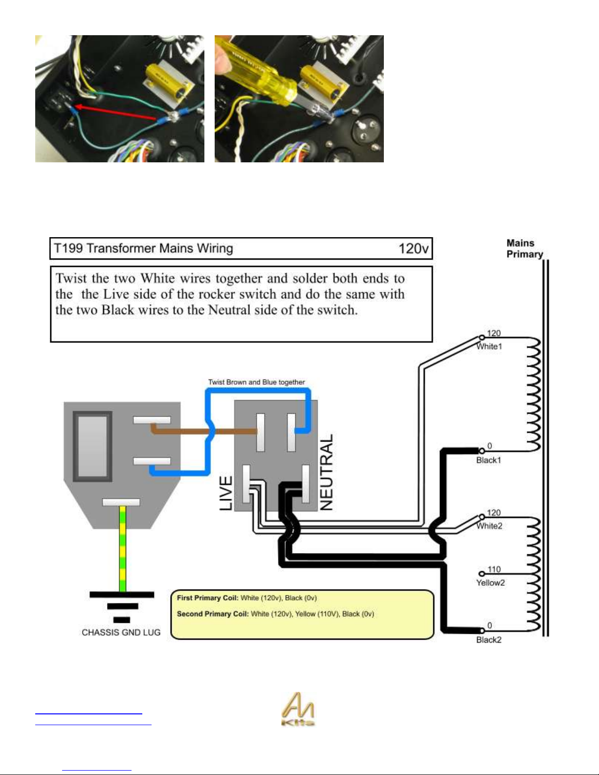
AC Wiring Guide (T-199 Mains Transformer)
The following diagrams show the mains wiring configurations for the various world voltages. It is recommended that you
cross out the ones that don't apply to you so that you can't follow the wrong one.
Page 54

Copyright © 2010 AudioNote Kits
www.AudioNoteKits.com
audionotekits@rogers.com
Page 54
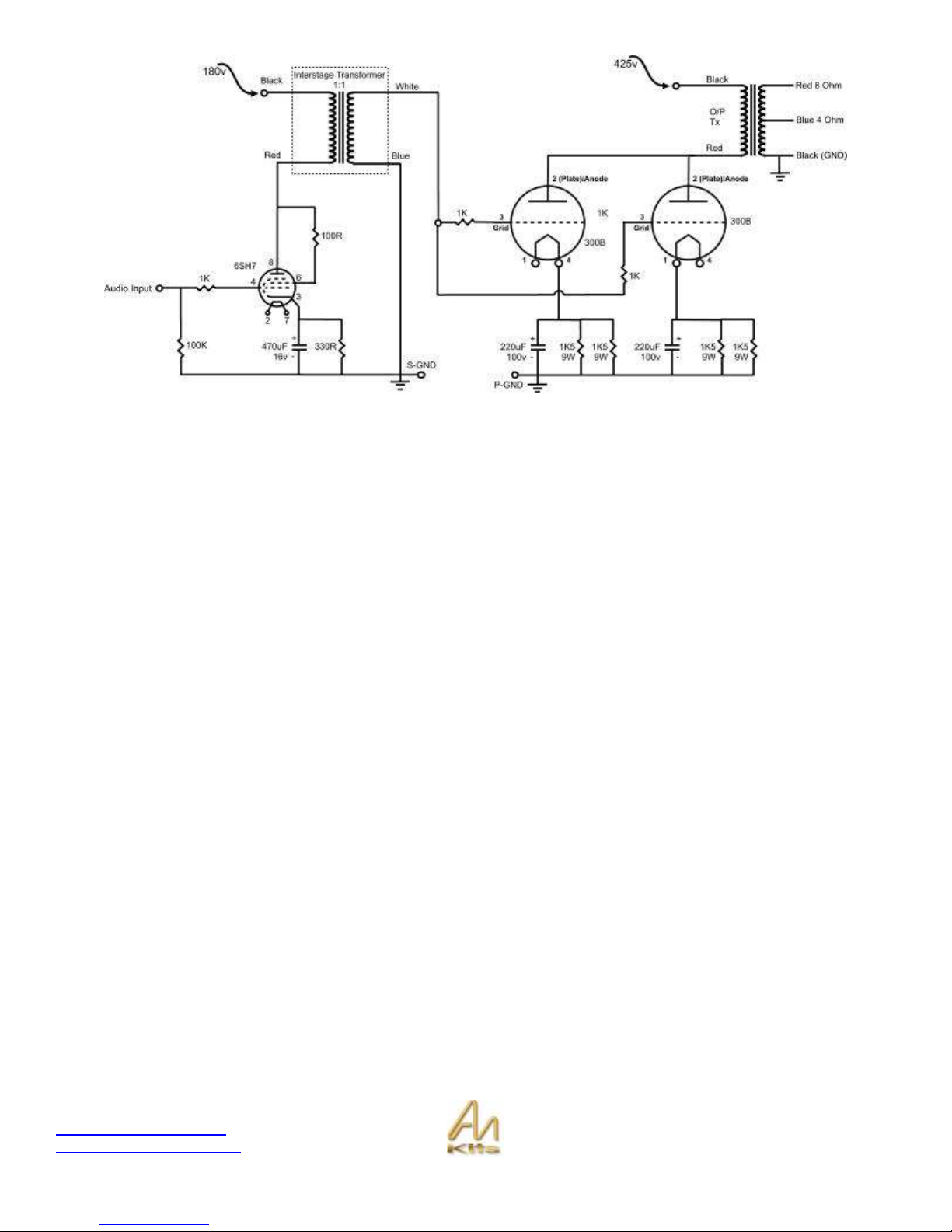
Full Schematic
Page 55
Copyright © 2010 AudioNote Kits
www.AudioNoteKits.com
audionotekits@rogers.com
Page 55
Wiring Reference 1
Page 56

Copyright © 2010 AudioNote Kits
www.AudioNoteKits.com
audionotekits@rogers.com
Page 56
Wiring Reference 2
 Loading...