

Page 1
User Manual
All - In Se a l e r
v e r
D 552 AVT / D 552 AVTS
User Manual
www.audion.com
All-In Sealer
D 552 AVT / D 552 AVTS
D 552 AVT(S) ENG Rev.04
Page 2

All-In Sealer
D 552 AVT / D 552 AVTS
Original Instructions
All rights reserved.
No part of this publication may be reproduced and/or published by means of
print, photocopy, or in any other way, without prior written permission from
Audion Elektro BV.
Audion Elektro BV reserves the right to modify the machine and/or change the
operating manual without prior notice.
Audion Elektro BV is not liable for any damage caused by specifications
deviating from the standard version.
Although this manual was compiled with the utmost care, Audion Elektro BV
does not accept any liability for any mistakes it may contain and/or the
consequences of any incorrect interpretation of its contents.
Audion Elektro BV is not liable for any damage or problems resulting from the
use of parts other than original parts. If this manual does not provide
instructions for certain repairs, adjustments or maintenance, please contact your
dealer or Audion Elektro BV.
Page 3

Please read this operating
manual carefully before using
the sealer or carrying out
maintenance on it.
[*****]
The sealer is part of the Audion
product range. We also provide:
• Impulse sealers.
• Heat sealers.
• Continuous sealers.
• Vacuum sealers.
• Vacuum chambers.
• Shrink machines.
• Validatable sealers.
• Form, fill and seal machines.
Since its inception in 1947, Audion
has gained a lot of experience and
expertise with a wide variety of
sealing and packaging machines.
Our solutions for packaging
problems are unique. Our many
years of experience together with
our modern production, assembly
and testing methods ensure that our
packaging machines meet the
highest quality standards. We can
also customise the machines
according to your specific
requirements.
Audion is the right supplier for a
packaging machine that is geared to
your requirements.
[*****]
Page 4

All-In Sealer
D 552 AVT / D 552 AVTS
4 Table of Contents
Table of Contents
1 Introduction .......................................................................................................................... 6
1.1 Manufacturer .......................................................................................................... 6
1.2 Machine Type Plate ................................................................................................ 6
1.3 Warranty Conditions and Liability ......................................................................... 6
2 Safety .................................................................................................................................... 8
2.1 Symbols Used in This Manual ............................................................................... 8
2.2 User ......................................................................................................................... 8
2.2.1 Operating Personnel .......................................................................................... 8
2.2.2 Maintenance Personnel ..................................................................................... 8
2.3 Safety Instructions ................................................................................................. 9
2.3.1 General Safety Instructions ............................................................................... 9
2.3.2 What to do in case of Fire ................................................................................ 10
2.3.3 Use for Special Applications ........................................................................... 10
2.4 Safety Provisions .................................................................................................. 11
2.5 Safety symbols ..................................................................................................... 11
3 Installation .......................................................................................................................... 12
3.1 Unpacking the Sealer ........................................................................................... 12
3.2 Placing the Sealer ................................................................................................. 12
3.3 Connecting the Sealer .......................................................................................... 12
3.4 Adjusting the Sealer ............................................................................................. 13
3.4.1 Adjusting the Sealing Unit Height .................................................................. 13
3.4.2 Adjusting the Horizontal Distance for the Conveyor Belt .............................. 13
3.4.3 Adjusting the Conveyor Belt Height ............................................................... 14
4 Description of the Sealer ................................................................................................... 15
4.1 Function ................................................................................................................ 15
4.2 Overview of the Sealer ......................................................................................... 16
4.3 Control Panel ........................................................................................................ 17
4.3.1 Cool Run mode ................................................................................................ 18
5 Operation ............................................................................................................................ 19
5.1 Preparing the Sealer for Production .................................................................... 19
5.1.1 Switching on the Sealer .................................................................................. 19
5.1.2 Setting the Sealing Temperature and the Conveyor Belt Speed .................. 19
5.1.3 Switching on the heating, the cooling and the fan ........................................ 20
5.1.4 Starting the Sealer ........................................................................................... 21
5.2 Sealing .................................................................................................................. 21
5.3 Stopping the Sealer (STANDBY mode) ............................................................... 22
5.4 Emergency stop .................................................................................................... 22
5.4.1 Restarting After an Emergency Stop .............................................................. 23
5.5 Switching Off the Sealer Completely .................................................................. 23
6 Troubleshooting ................................................................................................................. 24
7 Maintenance ....................................................................................................................... 26
7.1 Maintenance Schedule ......................................................................................... 26
7.1.1 Daily maintenance ........................................................................................... 26
Page 5

Table of Contents 5
7.1.2 Weekly maintenance ....................................................................................... 26
7.1.3 Annual maintenance ........................................................................................ 26
7.2 Switching Off the Sealer and Opening the Protective Cover ............................. 27
7.3 Replacing the PTFE Belts ..................................................................................... 28
7.4 Replacing V-belts .................................................................................................. 30
7.5 Adjusting the V-belts ............................................................................................ 30
7.6 Replacing the heating elements .......................................................................... 31
7.7 Adjusting the Contact Force of the Heating Blocks ............................................ 33
7.8 Adjusting the Contact Force of the Press Rollers ............................................... 34
7.9 Adjusting the Contact Force for the Cooling Plates ............................................ 34
7.10 Adjusting the Contact Force of the After-press Rollers ...................................... 35
7.11 Adjusting the Conveyor Belt Tension.................................................................. 35
7.12 Motor Set-up......................................................................................................... 36
7.13 Correction factor ................................................................................................... 36
7.14 Reset to factory settings ...................................................................................... 36
8 Disposing of the Sealer ..................................................................................................... 37
8.1 WEEE Directive ..................................................................................................... 37
8.2 Correct Disposal for Reuse .................................................................................. 37
A Technical Information ........................................................................................................ 38
A.1. Dimension drawing .............................................................................................. 38
A.2. Technical Data ...................................................................................................... 39
B Electrical Diagram .............................................................................................................. 40
C Spare Parts ......................................................................................................................... 42
C.1. Wearing parts ....................................................................................................... 42
C.2. Exploded views .................................................................................................... 43
D Log ...................................................................................................................................... 55
D.1. Maintenance Log .................................................................................................. 55
E EC Declaration .................................................................................................................... 56
F Options .................................................................................................................................. 57
Page 6
All-In Sealer
D 552 AVT / D 552 AVTS
6 Introduction
1 Introduction
[*****]
1.1 Manufacturer
The sealer was manufactured by:
Audion Elektro BV
Hogeweyselaan 235
1382 JL Weesp
T
he Netherlands
Telephone:
+31 (0)294 491717
Fax:
+31 (0)294 491761
Email:
Export@audion.nl
Web:
www.audion.com
[*****]
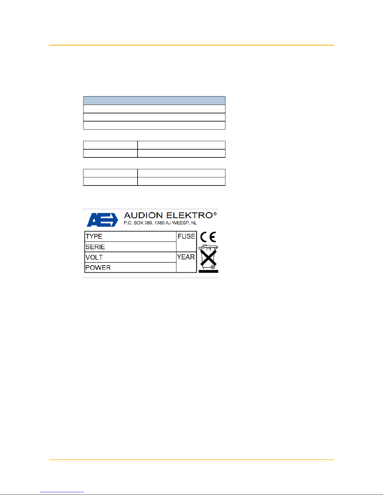
1.2 Machine Type Plate
The sealer has a CE marking. This means that the sealer meets the fundamental
health and safety requirements of the European Communities.
1.3 Warranty Conditions and Liability
Subject to the limitations stated below, we provide a 12-month warranty for the
products we deliver. This warranty is limited to manufacturing defects and
therefore does not cover any malfunctions caused by any form of wear, or any
part of the delivered product that is subject to wear.
• The warranty we provide for parts or accessories purchased from third parties
is limited to the warranty the third-party provided to us.
• The warranty is void if the other party and/or any third parties engaged by
them use the product in a way it is not intended for.
• The warranty is also void if the other party, and/or any third parties engaged
by them carries out work and/or modifications on the delivered product.
• Any parts we replace in order to meet our warranty obligations become our
property.
Page 7

Introduction 7
• Should the other party not meet obligation resulting from the agreement
entered into between the parties in whole or in part or in a timely manner, we
are not obliged to provide warranty for as long as that situation continues.
We exclude all liability to the extent that the liability is not regulated by law. Our
liability will never exceed the total amount of the order in question.
Subject to the generally applicable legal rules of public order and good faith, we
are not obliged to pay compensation to the other party or any third party for
damages of any nature whatsoever, incurred directly or indirectly, including
trading loss and damage to movable or immovable property or persons.
In no case are we liable for any damage resulting from or caused by using the
delivered product or its unsuitability for the purpose for which the other party
purchased it.
Page 8
All-In Sealer
D 552 AVT / D 552 AVTS
8 Safety
2 Safety
[*****]
2.1 Symbols Used in This Manual
The following symbols are used in this user manual:
[*****]
A tip on how a task can be carried out more efficiently.
[*****]
Instructions for carrying out a task in the correct manner.
[*****]
Danger of injury to the user or damage to the sealer if the instructions
are not observed.
[*****]
2.2 User
[*****]
The sealer should only be operated by authorised personnel.
[*****]
Improper use of the sealer may lead to serious personal injury and
considerable material damage.
[*****]
Keep bystanders at a distance. Do NOT allow unauthorised personnel
to operate the sealer.
[*****]
2.2.1 Operating Personnel
The company using the machine has organised a training session to inform its
operating personnel of the potential risks of unprofessional behaviour while
carrying out their tasks.
[*****]
Installation, maintenance and repair require specialised knowledge,
which is why these tasks should only be performed by maintenance
personnel.
[*****]
Observe the safety instructions in this user manual. Failure to observe
the safety instructions may cause unacceptable risks.
The operating personnel must be familiar with all chapters of this user manual
with the exception of ‘Installation’ and ‘Maintenance’. Always observe the
following safety instructions before using the sealer or carrying out any
maintenance work.
2.2.2 Maintenance Personnel
These personnel’s professional training, knowledge and experience, and
knowledge of the manufacturer’s terms enable them to carry out the assigned
work and immediately recognise any risks that may arise.
[*****]
Observe the safety instructions in this user manual. Failure to observe
the safety instructions may cause unacceptable risks.
The maintenance personnel must be familiar with all chapters of this user
manual. Always observe the following safety instructions before using the sealer
or carrying out any maintenance work.
Page 9

Safety 9
2.3 Safety Instructions
The sealer meets the fundamental health and safety requirements of the
European Community. This means that the sealer can be operated and
maintained safely if all safety instructions are carefully observed. However,
improper or careless use can create dangerous situations.
[*****]
Observe the safety instructions in this user manual. Always remain
alert to dangerous situations and avoid any improper or careless use.
[*****]
2.3.1 General Safety Instructions
Observe the following general safety instructions:
• Tie back long hair.
• Do not wear loose clothing or jewellery.
• Always wear the personal protective equipment (PPE) prescribed by the
company, such as safety shoes, gloves and goggles.
[*****]
U
se the PPE required on the shop floor, such as safety shoes, gloves
and goggles and/or hearing protection, in particular when carrying out
maintenance work.
• Check the operation of the sealer every day.
• Keep your hands away from dangerous parts of the sealer.
• Always leave protective covers in place during production.
• Never bypass or deactivate any safety provisions.
• The sealer should never be operated or maintained by people who are under
the influence of alcohol, medication and/or drugs.
• Only use sealable material that is suitable for the sealer.
• The user is obliged to observe the normally applicable hygienic measures.
• If you are not sure whether the sealer is working properly, switch it off
immediately and consult the maintenance personnel.
• Both the user and the sealer must be supervised while the sealer is in use.
• Do not switch the sealer back on until the malfunction has been repaired.
• Should any liquid or foreign object enter the machine, switch off the sealer
and immediately remove the plug from the wall socket and have the sealer
checked by maintenance personnel before using it again.
Page 10

All-In Sealer
D 552 AVT / D 552 AVTS
10 Safety
• Should an unusual event occur, such as the development of smoke, remove
the plug from the socket immediately and have the sealer checked by
maintenance personnel before using it again.
• Remove the plug from the socket before carrying out any maintenance work.
• Never open the sealer’s housing while it is connected to the mains power.
• Do not use any water, abrasive cleaning agents, chemical solvents or other
liquids when cleaning the sealer.
2.3.2 What to do in case of Fire
[*****]
NEVER use water to extinguish a fire. This may result in lifethreatening situations because the sealer may be electrically live.
Should the sealer catch fire, never use water to extinguish the fire. Because the
machine is live, this may result in life-threatening situations. A fire extinguisher
must be within reach when the sealer is in use. The following types of fire
extinguishers are suitable to extinguish a burning sealer.
• Powder extinguisher.
• Foam extinguisher.
2.3.3 Use for Special Applications
[*****]
If the machine is used in a special environment, the company using the
machine must ensure that any instructions specific to that
environment are observed.
• If the machine is used in a sterile environment or cleanroom, the company
using the machine must ensure that any instructions specific to that
environment are observed.
• If the machine is used for the packaging of medical instruments, the company
using the machine must ensure that any instructions specific to that
environment are observed.
• If the machine is used for the packaging of food, the company using the
machine must ensure that any instructions specific to that environment are
observed.
Page 11

Safety 11
2.4 Safety Provisions
The sealer has the following safety provisions:
1. Safety covers.
− Electrical and mechanical parts in the housing are protected.
2. Metal parts are earthed.
− No dangerous voltage can develop between (external) metal parts and
the earth.
3. Fuse in 230 V circuit.
− If the maximum current is exceeded, the fuse will blow, cutting off the
power supply.
4. Emergency stop button
− In the event of a hazard, this can be used for switching off the sealer
immediately and completely.
2.5 Safety symbols
The following safety symbols have been applied on the All-In Sealer:
[*****]
Hot surfaces
On the front of the All-In Sealer on the cover.
There are heating elements and it may
therefore get hot.
[*****]
Page 12

All-In Sealer
D 552 AVT / D 552 AVTS
12 Installation
3 Installation
[*****]
3.1 Unpacking the Sealer
Check the following when unpacking the sealer:
1. Have all parts and accessories been delivered?
− Sealer
− User manual
[*****]
The sealer is packaged in environmentally friendly material that may
be disposed of as ordinary household waste.
[*****]
Keep the crate and the packaging material so that the sealer can be
transported safely again if necessary.
[*****]
3.2 Placing the Sealer
[*****]
1.
Move the sealer to the desired location.
2. Lock the wheels by pressing the brakes
down with your foot.
[*****]
3.3 Connecting the Sealer
*****]
1.
Check that the main switch is in the ’0’
position.
Page 13
Installation 13
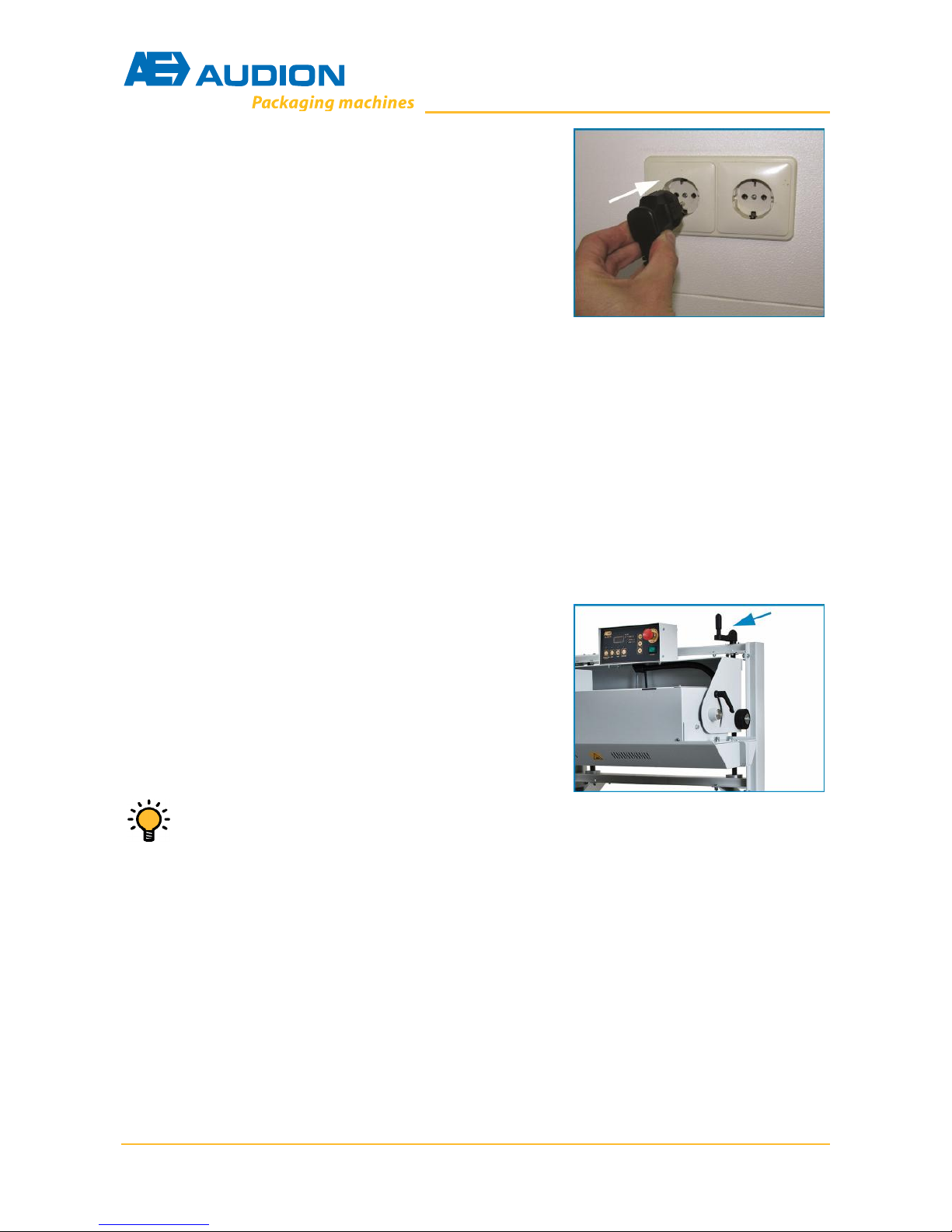
2.
Insert the plug in the wall socket.
[*****]
3.4 Adjusting the Sealer
The following adjustments can be made:
• The height of the sealing unit with respect to the conveyor belt; to adjust for
the height of the bags.
• The horizontal distance between conveyor belt and sealing unit; to adjust for
the positioning of the bags on the conveyor belt.
• The height of conveyor belt with respect to the floor, to adjust the working
height.
3.4.1 Adjusting the Sealing Unit Height
The sealing unit height can be adjusted as follows:
[*****]
1.
Set the sealing unit height by turning the
crank.
[*****]
The top of the bag to be sealed should b
e able to move freely along the
top of the infeed guide.
[*****]
3.4.2 Adjusting the Horizontal Distance for the Conveyor Belt
The horizontal distance of the conveyor belt with respect to the sealing unit is
adjusted as follows:
[*****]
Page 14
All-In Sealer
D 552 AVT / D 552 AVTS
14 Installation
1.
Loosen the four locking
bolts a few turns.
2. Adjust the position of the conveyor belt
with respect to the sealing unit by shifting
the conveyor belt.
3. Tighten the locking bolts again.
[*****
The position of the conveyor belt must be set so that the bags that are
to be sealed are in the middle of the conveyor belt.
[*****]
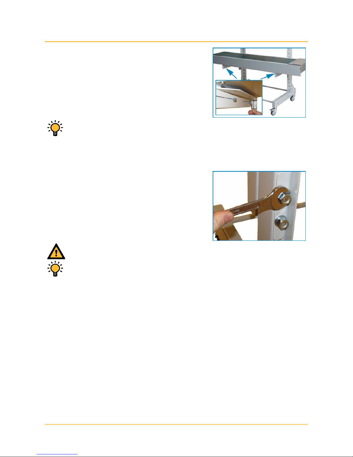
3.4.3 Adjusting the Conveyor Belt Height
The conveyor belt height can be adjusted with respect to the sealing unit as
follows:
[*****]
1.
Loosen the two mounting nuts at the back
of the conveyor belt brackets
2. Take the conveyor belt from the frame.
3. Position the conveyor belt on the frame at
the desired height.
4. Tighten the mounting nuts again.
[*****]
Make sure two persons take the conveyor belt from the frame and reposition it.
[*****]
The height of the conveyor belt must line up with the infeed and
outfeed belts.
[*****]
Page 15

Description of the Sealer 15
4 Description of the Sealer
[*****]
4.1 Function
The All-In Sealer is a band sealer for packaging a wide variety of products in large
quantities. The products are packaged in ready-to-use bags and then sealed. The
sealer can be used for sealing ready-made bags made of polyethylene (PE),
polypropylene (PP), thin PVC and various laminates with thicknesses of between
20µm and 150µm.
[*****]
Never use the All-In Sealer for any other purpose.
[*****]
The sealer is not suitable for the following applications:
• use in cleanroom environments
• use in medical or sterile environments
• use in explosive environments
• use with toxic, suffocating or irritant gases
• use in dusty environments
Page 16
All-In Sealer
D 552 AVT / D 552 AVTS
16 Description of the Sealer
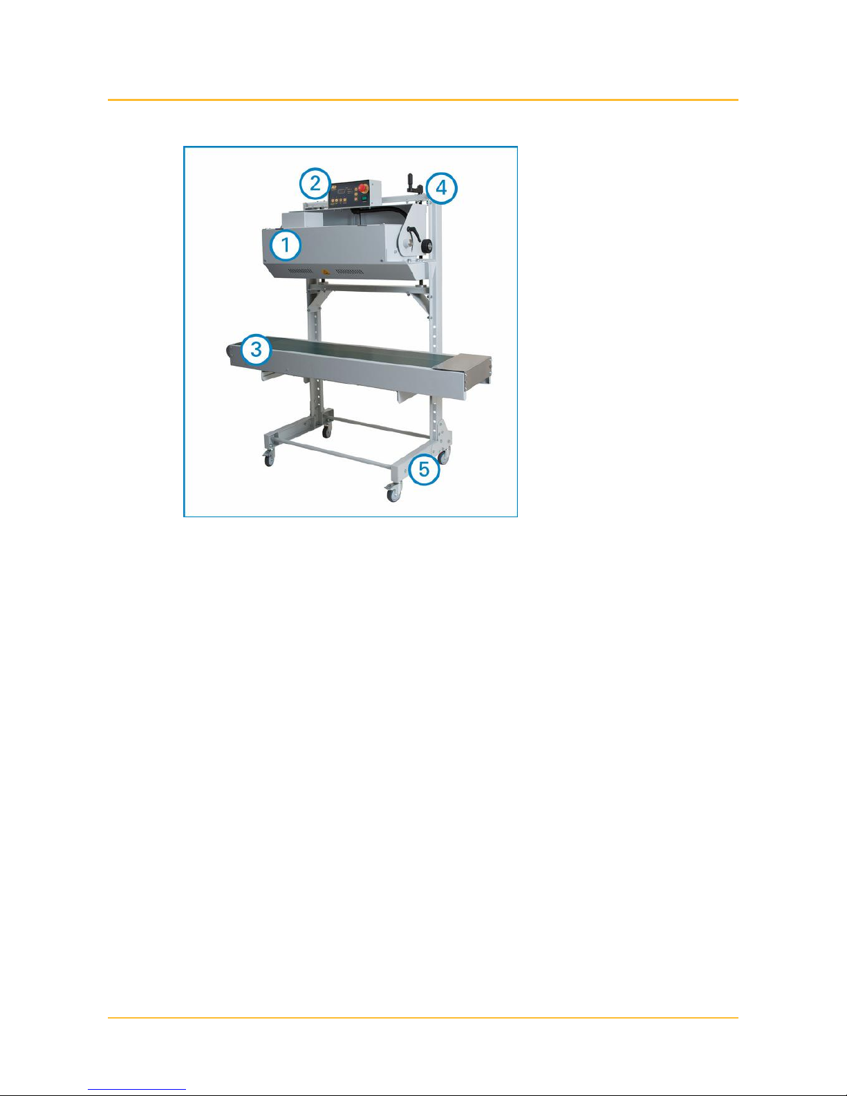
4.2 Overview of the Sealer
[*****]
1. Housing
2. Control panel
3. Conveyor belt
4. Setting the distance and height of the sealing unit with respect to the
conveyor belt.
5. Frame with wheels
The sealer consists of a wheeled frame on which there is a conveyor belt and a
housing. The housing comprises the electrical and drive components; the
operating panel is mounted on top of the housing. During maintenance work, the
housing can be tilted to make the interior easily accessible.
The conveyor belt transports the bags that are to be sealed past the heating
blocks, the press rollers, the cooling plates and the after-press rollers that are
located inside the housing.
The height of the conveyor belt can be adjusted to let it line up seamlessly with
the infeed and outfeed belts. The vertical distance between the conveyor belt and
the housing can also be adjusted so that bags of various different heights can be
sealed. The horizontal position of the conveyor belt with respect to the sealing
unit can be adjusted to position the bags as centrally as possible on the conveyor
belt.
Page 17

Description of the Sealer 17
4.3 Control Panel
[*****]
[*****]
1.
Display
Gives the current sealing temperature, speed or
an error message. The setpoint value will be
shown while the settings are being adjusted.
2.
Prog
Press this to change the settings menu of the
sealer. A LED next to the button will show which
setting is being adjusted:
Temp, the sealing temperature.
Speed, the conveyor belt speed.
Sync., synchronising the sealing speed and the
speed of the conveyor belt.
3.
Up/Down
Press these to increase or reduc
e a setting.
4.
Emergency stop button
If a dangerous situation occurs, this will switch off
the sealer immediately and completely.
5.
Start/Stop
Press to start or stop the sealer. A LED above the
button shows whether the sealer is switched on or
off. If the current sealing temperature is above
80°C when the sealer is switched off, it will first
switch to ‘cool run’ mode.
6.
Heat
Press this to switch the heating on or off. A LED
above the button indicates whether the function is
switched on or off.
7.
Fan
Press this
to switch the fan on or off. A LED above
the button indicates whether the function is
switched on or off.
8.
Motor
Press this to switch the motor on or off. A LED
above the button shows whether the function is
switched on or off.
9.
Main switch
Switch for tur
ning the sealer on or off.
Page 18

All-In Sealer
D 552 AVT / D 552 AVTS
18 Description of the Sealer
4.3.1 Cool Run mode
The ‘cool run’ mode avoids burnt spots on the PTFE belts. After the machine has
been stopped, the heater is switched off; however, the fan and the motor will
continue to run. When the sealing temperature has dropped below 80°C, the
sealer is switched to standby mode. The fan and the motor will then also be
switched off.
Page 19

Operation 19
5 Operation
[*****]
5.1 Preparing the Sealer for Production
[*****]
5.1.1 Switching on the Sealer
Switch the sealer on as follows:
[*****]
1.
Set the MAIN SW
ITCH to ’1’.
2. Turn the EMERGENCY STOP BUTTON
clockwise if necessary to reset it.
[*****]
Put the plug in the socket first if necessary.
[*****]
5.1.2 Setting the Sealing Temperature and the Conveyor Belt Speed
The sealing temperature and conveyor speed can be adjusted as follows:
[*****]
1.
Press the
PROG
button until the TEMP LED
is lit.
2. Press the ARROW keys to raise or lower
the sealing temperature.
[*****]
The guideline sealing temperature is 100°C
[*****]
[*****]
3.
Press the PROG button until the SPEE
D
LED is lit.
4. Press the ARROW button to increase or
reduce the speed of the conveyor belt.
[*****]
The guideline value for the conveyor belt speed is 50.
[*****]
[*****]
Page 20

All-In Sealer
D 552 AVT / D 552 AVTS
20 Operation
5.
Press the PROG button until the current
sealing temperature is shown in the
display again.
[*****]
The TEMP LED will blink if the setpoint temperature differs from the
current sealing temperature by more than 5°C.
[*****]
Make a number of trial seals and readjust the sealing temperature and
speed as necessary.
[*****]
5.1.3 Switching on the heating, the cooling and the fan
Switch on the heating, the cooling and the fan as follows:
[*****]
1.
Press the HEAT button.
2. Press the MOTOR button.
[*****]
The heating and the transport motor must always be switched on
before use.
[*****]
[*****]
3.
Press the FAN button if necessary.
[*****]
If a paper or aluminium laminate film is being used, the FAN does not
have to be switched on.
Do be sure to switch on the fan when using PE films.
[*****]
Page 21

Operation 21
5.1.4 Starting the Sealer
Start the sealer as follows:
[*****]
1.
Press the START/STOP button.
2. Wait until the TEMP LED has stopped
blinking.
[*****]
The sealer has now reached the set temperature and is ready for
sealing.
[*****]
5.2 Sealing
Bags are sealed as follows:
[*****]
1.
Place the bags on the con
veyor belt and
guide the bag into the infeed guide.
[*****]
Make a number of trial seals first to check that the settings are
correct. Adjust the sealing temperature and conveyor belt speed as
necessary.
[*****]
Page 22

All-In Sealer
D 552 AVT / D 552 AVTS
22 Operation
5.3 Stopping the Sealer (STANDBY mode)
The sealer can be stopped and put in Standby mode after use as follows:
[*****]
1. Press the START/STOP button.
[*****]
The sealer now switches to Standby mode and the display shows "---".
If the sealing temperature is above 80°C, the sealer will first switch to
COOL RUN mode. The heating is switched off and the fan and motor
continue to run until the sealing temperature has dropped to below
80°C. The display will alternate between "c-r" and the current sealing
temperature.
The sealer is then switched to STANDBY mode.
[*****]
If the sealer is not going to be used for a lengthy period, it is better to
turn it off completely using the MAIN SWITCH.
[*****]
5.4 Emergency stop
In the event of an emergency, switch the sealer off completely as follows:
[*****]
1. Press the EMERGENCY STOP BUTTON.
[*****]
In emergency situations, always use the emergency stop button
immediately.
Do not use the emergency stop button to switch off the sealer under
normal circumstances.
[*****]
Page 23

Operation 23
5.4.1 Restarting After an Emergency Stop
The sealer can be restarted after an emergency stop as follows:
[*****]
Make sure that whatever caused the emergency stop has been
corrected before restarting the sealer.
[*****]
1.
Turn the EMERGENCY STOP BUTTON
clockwise to reset it.
2. Press the START/STOP button.
[*****]
The sealer is now ready to be used again. The ‘TEMP’ LED may possibly
be blinking; in that case, the sealer has to heat up again first.
[*****]
5.5 Switching Off the Sealer Completely
The sealer can be switched off completely as follows:
[*****]
1.
Set the MAIN SWITCH to '0'.
[*****]
Make sure that the sealer is in Standby mode before it is switched off
completely (see 'Stopping the Sealer (STANDBY mode)').
[*****]
Page 24

All-In Sealer
D 552 AVT / D 552 AVTS
24 Troubleshooting
6 Troubleshooting
[*****]
Troubleshooting may only be performed by authorised maintenance
personnel.
[*****]
In the event of a malfunction, always remove the plug from the socket
before attempting to solve the problem.
[*****]
If the problem cannot be solved using the following troubleshooting
table, please contact your dealer or Audion.
[*****]
[*****]
Problem
Cause
Solution
The sealer does not do
anything.
The main switch is set to
'0'.
Switch the sealer on.
The plug is not inserted
into the wall socket or
has not been inserted
properly.
Put the plug in the
socket
properly.
The power has been cut.
Check the power supply.
The emergency stop
button has been pressed.
Reset the emergency stop
button.
Internal fault.
Contact your dealer or
Audion.
The seal is not neat and
tidy.
The sealing temperature
is not set correctly.
Readjust the sealing
temperature.
The conveyor belt speed
is not set correctly.
Readjust the conveyor
belt speed.
The heating blocks and/or
the PTFE belts are dirty.
Clean the heating blocks
and/or the PTFE belts.
The seal is not be
ing
cooled properly.
Switch the cooling on.
The heating block, the
cooling plate and/or the
press rollers are still
raised.
Put the heating block,
cooling plate and/or press
rollers back in the lowest
position.
The PTFE belts are worn.
Replace the PTFE
belts.
The cooling is not
working
The fan is not on.
Switch the fan on.
The cooling plate position
is too high.
Adjust the cooling plate
correctly.
Internal fault
Contact your dealer or
Audion.
Error code E1
Incorrect frequency
setting (50 Hz or 60 Hz PCB jumpers.
Check the main frequency
and set the PCB jumpers
correctly.
Error code E2
Loose wire to the
temperature sensor
(Pt100).
Check the connections in
the temperature sensor
wiring (Pt100).
Error code E3
Short circuit in the
temperature sensor
(Pt100).
Replace the temperature
sensor (Pt100).
Page 25

Troubleshooting 25
The conveyor belt is not
moving.
The speed is set to '0'.
Set the speed higher.
Internal fault.
Contact your dealer or
Audion.
[*****]
Page 26

All-In Sealer
D 552 AVT / D 552 AVTS
26 Maintenance
7 Maintenance
[*****]
Maintenance should only be performed by authorised maintenance
personnel.
[*****]
Always remove the plug from the socket before carrying out any
maintenance work.
[*****]
Do not use any water, abrasive cleaning agents, chemical solvents or
other liquids when cleaning the machine.
[*****]
The maintenance schedule is based on normal use. The frequency of
maintenance must be increased if the machine is used intensively, or
under extreme conditions.
[*****]
Always keep a log of all maintenance work. An example is provided as
an annex.
[*****]
7.1 Maintenance Schedule
[*****]
7.1.1 Daily maintenance
[*****]
Daily maintenance should be carried out by the operating personnel
(see Foreword)
[*****]
Part
Work
PTFE belts
Check that the PTFE belts are clean. Clean
with a damp cloth if necessary.
He
ating blocks
check that the heating blocks are clean.
Clean with a damp cloth if necessary.
[*****]
7.1.2 Weekly maintenance
[*****]
Weekly maintenance should be carried out by authorised maintenance
staff (see Foreword).
[*****]
Part
Work
Drive
Check the
rotating parts and chains.
Lubricate as necessary.
V-belts
Check the V
-
belts for cracks and check the
tension.
Conveyor belt
Check the conveyor belt for cracks and check
its tension.
Cleaning
Clean the sealer with a damp cloth and mild
soap (for example, all-purpose cleaner).
[*****]
7.1.3 Annual maintenance
[*****]
Annual maintenance should be carried out by authorised maintenance
staff (see Foreword).
[*****]
Part
Work
Earthing system
Check that the earthing complies with NEN
3140 or EN 50110-1.
[*****]
Page 27

Maintenance 27
7.2 Switching Off the Sealer and Opening the Protective
Cover
Open the protective cover as follows:
[*****]
1.
Set the main switch to ’0’.
2. Remove the plug from the socket.
[*****]
Never carry out maintenance on the sealer while it is live.
[******]
3.
Loos
en the two locking handles at the side
a few turns.
4.
Tilt the housing so that the sealing slit is at
the front.
5. Tighten the two locking handles again.
[******]
6.
Loosen the two bolts near the infeed slit.
[******]
7.
Open the protective cover.
[*****]
Warning! The heating blocks may still be hot, even if the sealer has
been switched off for a while.
[******]
Page 28

All-In Sealer
D 552 AVT / D 552 AVTS
28 Maintenance
7.3 Replacing the PTFE Belts
[*****]
Warning! The heating blocks may still be hot, even if the sealer has
been switched off for a while.
[******]
Replace the PTFE belts as follows:
[*****]
1.
Move the cooling plate, the after
-
press
roller and the heating block to their
uppermost position.
[*****]
Pull the lifting pin up and turn the lifting plate in such a way that it
protrudes above the edge of the protective cover.
[******]
2.
Push the two tension rollers inwards until
they lock in place.
[*****]
When a tension roller is pushed inwards, the locking pin falls into a
recess, which prevents the tension roller from springing back.
[******]
3.
Remov
e the V
-
belts by pushing them off
the pulleys with a rotating motion.
Page 29

Maintenance 29
4.
Remove the old PTFE belts and put the
new ones in place.
[*****]
Make sure there are no creases or folds in the PTFE belts. This can
make them break during use.
[*****]
5.
Pull the
tension roller locking pins
upwards and let the tension rollers spring
back gently.
[*****]
Make sure that the PTFE belts run smoothly over the rollers.
[******]
6.
Place the V
-
belts back over the pulleys.
[*****]
Make sure that the V-belts run smoothly over the rollers, with the
serrated side facing outwards.
[******]
7.
Move the cooling plates, the after
-
press
roller and the heating block back to their
lowest position.
[*****]
Pull the lifting pin up and turn the lifting plate so that the lifting pin
can go back down all the way again.
[******]
Page 30

All-In Sealer
D 552 AVT / D 552 AVTS
30 Maintenance
7.4 Replacing V-belts
Replace the V-belts as follows:
[*****]
1.
Remove the V
-
belts by pushing them off
the pulleys.
2. Put the new V-belts back over the pulleys.
[*****]
Make sure that the V-belts run smoothly over the rollers, with the
serrated side facing outwards.
[******]
7.5 Adjusting the V-belts
The V-belts can be adjusted as follows:
[*****]
1.
Loosen the nut at the back of the shaft by
one full turn.
[*****]
Do not undo the nut completely, or else the tension roller will not stay
suspended.
[*****]
2.
Slide the tension roller to the left or right
to increase or decrease the V-belt tension
respectively.
3. Tighten the bolt at the back of the shaft
again.
[*****]
The long belts must be able to move up and down about 1 cm in the
middle; for the short belts, the play must be 0.5 cm.
[*****]
A V-belt that has to be tensioned frequently is worn and should be
replaced.
[******]
Page 31

Maintenance 31
7.6 Replacing the heating elements
Replace the heating elements as follows:
[*****]
1. Loosen the clamping screws in the
terminal block.
2. Pull the wires out of the terminal block.
3. Cut the tie-wraps away.
4. Move the heating block to its uppermost
position.
[*****]
Pull the lifting pin up and turn the lifting plate in such a way that it
protrudes above the edge of the protective cover.
[*****]
5. Loosen the mounting bolts.
6. Remove the heating block from the
machine.
7. Loosen the hex socket bolt at the back of
the heating block.
8. Take the heating element out of the
heating block.
9. Put a new heating element in place.
10. Carefully tighten the hex socket bolt at the
back of the heating block.
[*****]
Do not tighten the hex socket bolt too far, or the heating element may
get damaged.
[*****]
Page 32

All-In Sealer
D 552 AVT / D 552 AVTS
32 Maintenance
11.
Push the connecting wires through the
opening.
12. Put back the heating blocks.
13. Tighten the mounting bolts again.
[*****]
Note that the upper heating block should still be able to move up and
down a little bit after the mounting bolts are tightened.
[*****]
14.
Insert the connecting wires back in the
terminal block.
[*****]
15.
Tighten the terminal block screws again.
16. Fix the connecting wires in place again
with tie-wraps.
[*****]
Take care to connect the wires in the correct positions.
[*****]
Page 33

Maintenance 33
17.
Move the heating block back to its lowest
position.
[*****]
Pull the lifting pin up and turn the lifting plate so that the lifting pin
can go back down all the way again.
[*****]
7.7 Adjusting the Contact Force of the Heating Blocks
The heating blocks can be adjusted as follows:
[*****]
1.
Turn the adjuster
nut to
alter the contact
force.
[*****]
T
ry to keep the contact force as low as possible in order to minimise
wear and tear on the PTFE belts.
If necessary, the contact force can be increased for materials that are
difficult to seal. Always check that the bag does not get blocked or
stuck during sealing.
[*****]
Turn anticlockwise to increase the contact force and clockwise to
reduce it
[*****]
Note that the adjustment depends on the position (horizontal or
vertical) of the housing.
[*****]
Adjust both nuts equally.
[*****]
Page 34

All-In Sealer
D 552 AVT / D 552 AVTS
34 Maintenance
7.8 Adjusting the Contact Force of the Press Rollers
The press rollers can be adjusted as follows:
[*****]
1. Turn the adjuster nuts to set the contact
force.
[*****]
Try to keep the contact force as low as possible in order to minimise
wear and tear on the PTFE belts.
If necessary, the contact force can be increased for materials that are
difficult to seal. Always check that the bag does not get blocked or
stuck during sealing.
[*****]
Turn anticlockwise to increase the contact force and clockwise to
reduce it
[*****]
Note that the adjustment depends on the position (horizontal or
vertical) of the housing.
[*****]
7.9 Adjusting the Contact Force for the Cooling Plates
The cooling plates can be adjusted as follows:
[*****]
1. Tu
rn the adjuster nut to alter the contact
force
[*****]
[*****]
Try to keep the contact force as low as possible in order to minimise
wear and tear on the PTFE belts.
If necessary, the contact force can be increased for materials that are
difficult to seal. Always check that the bag does not get blocked or
stuck during sealing.
[*****]
Turn anticlockwise to increase the contact force and clockwise to
reduce it
[*****]
Note that the adjustment depends on the position (horizontal or
vertical) of the housing.
[*****]
Page 35

Maintenance 35
7.10 Adjusting the Contact Force of the After-press Rollers
The after-press rollers can be adjusted as follows:
[*****]
1.
Turn the adjuster nut to alter the contact
force.
[*****]
Try to keep the contact force as low as possible in order
to minimise
wear and tear on the PTFE belts.
If necessary, the contact force can be increased for materials that are
difficult to seal. Always check that the bag does not get blocked or
stuck during sealing.
[*****]
Turn anticlockwise to increase the co
ntact force and clockwise to
reduce it
[*****]
Note that the adjustment depends on the position (horizontal or
vertical) of the housing.
7.11 Adjusting the Conveyor Belt Tension
The conveyor belt can be adjusted as follows:
[*****]
1.
Loosen the two locking n
uts on the
underside of the conveyor belt a few turns.
2.
Turn the tension bolts to adjust the
tension.
3. Tighten the two locking nuts again.
[*****]
Turn clockwise to increase the conveyor belt tension and
anticlockwise to reduce it.
Make sure the tension is the same on both sides so that the conveyor
belt is not pulled out of line.
Page 36

All-In Sealer
D 552 AVT / D 552 AVTS
36 Maintenance
7.12 Motor Set-up
The machine has an automatic motor set-up function. This motor set-up function
must be carried out when a motor is replaced. During this set-up the motor will
run at full speed for a few seconds. Be aware that the machine can run safely for
a few seconds.
To perform a motor set-up follow the next steps:
• Select the ‘SPEED’ mode with the ‘PROG’ button.
• Press the ‘PROG’ button for 5 seconds till ‘SP1’ appears in the display.
• Start the set-up routine by pressing the ‘PROG’ button. The motor will run at
maximum speed for a few seconds.
• End the function by pressing the ‘PROG’ button for 5 seconds till the SPEED
settings appear on the display.
7.13 Correction factor
The machine has correction factors to adjust the motor if necessary. This factor
(%) will affect the motor output. If set at e.g. 90 the motor will run slower and set
at e.g. 110 the motor will run faster.
To perform a motor set-up follow the next steps:
• Select the ‘SPEED’ mode with the ‘PROG’ button.
• Press the ‘MOTOR’ and ‘PROG’ button simultaneous for 5 seconds till ‘CF1’
appears in the display.
• Press the ‘PROG’ button.
• Set the CF1 setting with the ‘UP’ or ‘DOWN’ button. (Minimum 85 and
maximum 115).
• Press the ‘PROG’ button to return to ‘CF1’.
• End the function by pressing the ‘PROG’ button for 5 seconds till the SPEED
settings appear on the display.
7.14 Reset to factory settings
The machine has a function to reset all settings to the original factory settings.
Note that if you reset the machine all settings prior made will be lost.
To perform a reset follow the next steps:
• Switch the main power OFF.
• Keep the ‘START/STOP’- and the ‘PROG’ button pressed, while the main power
is switched ON, until ‘rES’ appears in the display.
• Perform a motor set-up.
• Adjust the correction factor if necessary.
Page 37

Disposing of the Sealer 37
8 Disposing of the Sealer
[*****]
Correct disposal of machines and equipment helps protect the
environment and public health.
[*****]
8.1 WEEE Directive
[*****]
In accordanc
e with the European Directive on waste electrical and
electronic equipment (WEEE), the pictogram shown here indicates
that the machine or piece of equipment to which it has been applied
is to be collected separately from other waste and may not be
disposed of together with other waste.
[*****]
8.2 Correct Disposal for Reuse
The machine or piece of equipment is to be presented to a disposal station or, in
case of replacement, to the supplier of the replacement machine or piece of
equipment.
For more information, please contact the local agency responsible for the
collection of waste and the like, or the municipal waste depot.
[*****]
The owner of the machine or piece of equipment is responsible for the
correct disposal of the machine.
[*****]
Page 38

All-In Sealer
D 552 AVT / D 552 AVTS
38 Technical Information
A Technical Information
[*****]
A.1. Dimension drawing
Page 39

Technical Information 39
A.2. Technical Data
[*****]
General
Dimensions
See the dimensional drawing
Weight
120 kg
Ambient temperature
5 ºC to 40 ºC
Humidity
30% to 95% RH, non
-
condensing
Seal length
unlimited
Seal width
10 mm
Sealing
speed
Max. 10 metres per minute
IP value
IP20
Electrical
Voltage
230 V
- 16 A
Frequency
50-
60 Hz
Earthing
earthed
Power
1100 W
Mains power tolerance
< 10%
Fuse
4 AT
Length of power cable
± 1.8 m
Film
Min. film thickness
20 µm
Max. film thickn
ess 150 µm
Max. film insert
40 mm
Max. film width
unlimited
Bag dimensions
Max. weight (on conveyor belt)
10 kg
Max. bag length
420 mm
Max. volume
unlimited
Emissions
Noise
< 70 dB(A)
Hand/arm vibration
<2.5 m/s
2
[*****]
Page 40

All-In Sealer
D 552 AVT / D 552 AVTS
40 Electrical Diagram
B Electrical Diagram
[*****]
Maintenance to the electrical installation should only be performed by
authorised maintenance personnel.
[*****]
Always remove the plug from the socket before carrying out any
maintenance work.
[*****]
Page 41

Electrical Diagram 41
Page 42

All-In Sealer
D 552 AVT / D 552 AVTS
42 Spare Parts
C Spare Parts
[*****]
Only use original Audion parts for repairs and maintenance.
[*****]
Repairs and maintenance should only be performed by authorised
maintenance personnel.
[*****]
Always keep a set of recommended wear parts in stock so that a
defective part can be replaced quickly and the production process
resumed without delay.
[*****]
C.1. Wearing parts
*****]
Part
Qty per
machine
Item number
V-belt, large
2 685216
-14
V-belt, small
2 685205
-11
PTFE belt, width 25 mm
2
685206
-20
Heating element (PT100)
2
685209
-11
Set of wear
-
and-tear parts
2x V-belt, large
2x V-belt, small
4x PTFE belt, width 25 mm
2x heating element (PT100)
130-1203
[*****]
Page 43

Spare Parts 43
C.2. Exploded views
Page 44

All-In Sealer
D 552 AVT / D 552 AVTS
44 Spare Parts
Page 45

Spare Parts 45
Page 46

All-In Sealer
D 552 AVT / D 552 AVTS
46 Spare Parts
Page 47

Spare Parts 47
Page 48

All-In Sealer
D 552 AVT / D 552 AVTS
48 Spare Parts
Page 49

Spare Parts 49
Page 50

All-In Sealer
D 552 AVT / D 552 AVTS
50 Spare Parts
Page 51

Spare Parts 51
Page 52

All-In Sealer
D 552 AVT / D 552 AVTS
52 Spare Parts
Page 53

Spare Parts 53
Page 54

All-In Sealer
D 552 AVT / D 552 AVTS
54 Spare Parts
Page 55

Log 55
D Log
[*****]
Always keep a log of all maintenance work.
[*****]
Refer to the ’Maintenanc
e’ chapter for an overview of the maintenance
work to be carried out.
[*****]
Make a copy of the log and use it to sign off the maintenance work.
[*****]
D.1. Maintenance Log
[*****]
Maintenance*
Remarks/parts replaced
Date
Performed by
Initials
Weekly/
Monthly
Weekly/
Monthly
Weekly/
Monthly
Weekly/
Monthly
Weekly/
Monthly
Weekly/
Monthly
Weekly/
Monthly
Weekly/
Monthly
*Strike out that which does not apply.
[*****]
Page 56

All-In Sealer
D 552 AVT / D 552 AVTS
56 EC Declaration
E EC Declaration
Page 57

Options 57
Page 58

All-In Sealer
D 552 AVT / D 552 AVTS
58 EC Declaration
 Loading...