

Audiomedia AMD 808BT User Manual
AMD 808BT
BLUETOOTH CD/MP3 PLAYER
WITH RADIO AM/FM RDS
USB-SD/MMC BUILT IN
USER’S MANUAL
10R-02 1005
GB - 1
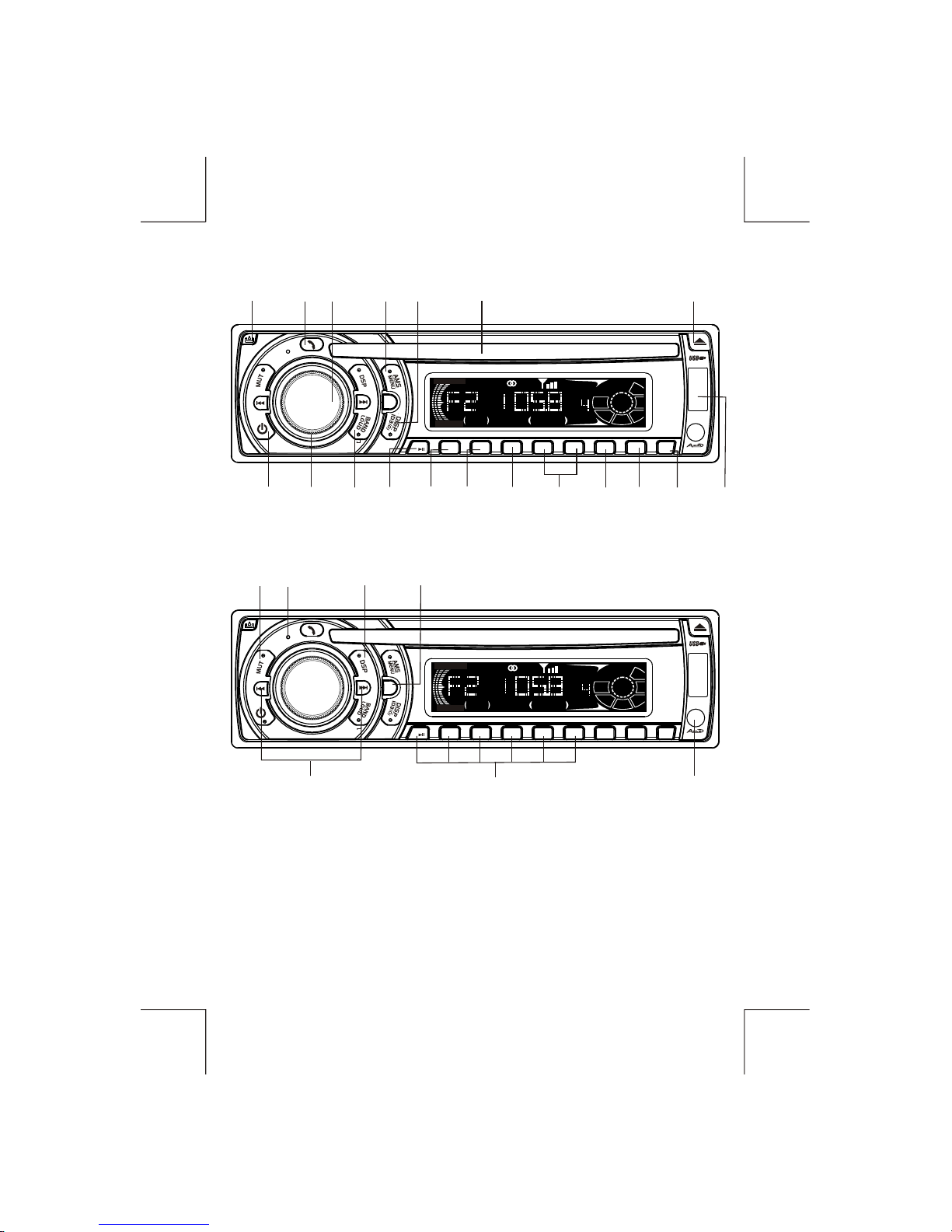
MOD
1
5
6
UP
PTY
TA AF
2
SCN
3
RPT
4
SHF
DN
PANEL
RELEASE
BUTTON
ENCODER
VOLUME
KNOB
TALK
BUTTON
CD
SLOT
AF
BUTTON
EJECT
BUTTON
TA
BUTTON
PTY
BUTTON
POWER
BUTTON
AMS/
MP3
MENU
BUTTON
BAND/
LOUDNESS/
MP3
ENTER
BUTTON
CD
PAUSE
BUTTON
CD
SCAN
BUTTON
CD
SHUFFLE
BUTTON
CD
REPEAT
BUTTON
FUNCTION
SELECT
BUTTON
DISPLAY/
ID3 TAG
INFORMATION
BUTTON
7
8
9
DIRECTORY
UP/ DOWN
MIC
ENTER
MOD
1
5
6
UP
PTY
TA AF
2
SCN
3
RPT
4
SHF
DN
PRESET MEMORY BUTTONS
(M1-M6)
DSP
BUTTON
MUTE
BUTTON
TUNING / SEEK /
TRACK / MP3 FILES SEARCH
UP/DOWN BUTTON
MODE
BUTTON
MICROPHONE
7
8
9
MIC
ENTER
CD
CLASSIC
POP
DSP
AF
TP
TA
LOCAL
LOUD
PTY
ST
MONO
CD
CLASSIC
POP
DSP
AF
TP
TA
LOCAL
LOUD
PTY
ST
MONO
USB
INPUT
AUX - IN
INPUT
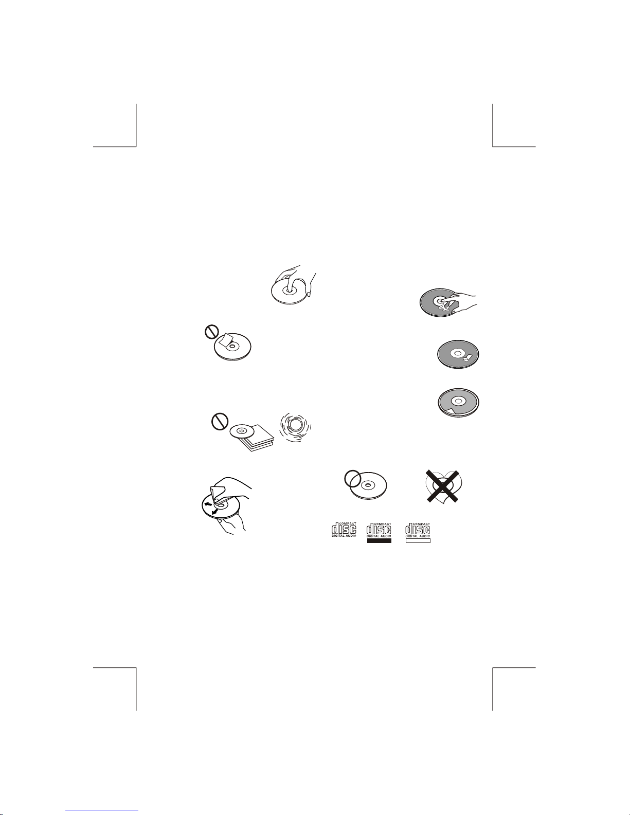
HANDLING COMPACT DISCS
MOISTURE CONDENSATION
NOTES ON CDs
P. 2
P. 3
P. 4
P. 1
P. 5
P. 6
P. 7
1.
2.
3.
4.
5.
NOTES ON DISCS
There are paste residue.
Ink is sticky (P.5).
Stickers that are beginning
to peel away, leaving a
sticky residue (P.6).
Labels are attached (P.7).
On a rainy day or in a very damp area, moisture may condense on the lenses inside the unit.
Should this occur, the unit will not operate properly. In such a case, remove the disc and wait
for about an hour until the moisture has evaporated.
A dirty or defective disc may cause sound
dropouts while playing. To enjoy optimum
sound, handle the disc as follows.
Handle the disc by its edge. To keep the
disc clean, do not touch the surface (P.1).
If you use the discs explained below, the
sticky residue can cause the CD to stop
spinning and may cause malfunction or
ruin your discs.
Do not use second-hand or rental CDs that
have a sticky residue on the surface (for
example, from peeled-off stickers or from
ink, or glue leaking from under the
stickers).
Do not stick paper or tape on the disc (P.2).
Before playing, clean the discs with an
optional cleaning cloth. Wipe each disc from
the centre out (P.4).
Do not use solvents such as benzine,
thinner,commercially available cleaners, or
antistatic spray intended for analog discs.
Do not expose the discs to direct sunlight or
heat sources such as hot air-ducts, or leave
them in a car parked in direct sunlight where
there can be a considerable rise in
temperature inside the car (P.3).
Do not use rental CDs with old labels that
are beginning to peel off.
Do not use your CDs with labels or
stickers attached.
**************
*******
*******
*******
*******
*******
*******
*******
*******
****
*******
*******
*******
*******
Do Not Use Special Shape CDs
Be sure to use round shape CDs only for
this unit and do not use any special shape
CDs. Use of special shape CDs may
cause the unit to malfunction.(P.8).
Be sure to use CDs with disc mark
Only for this unit.
RECORDABLE REWRITABLE
P. 8
CD-Rs and CD-RWs which have not
undergone finalization processing cannot
be played. (For more information on
finalization processing, refer to the manual
for your CD-R/CD-RW writing software or
CD-R/CD-RW recorder.) Additionally,
depending on the recording status, it may
prove impossible to play certain CDs
record on CD-R or CD-RW.
GB - 2
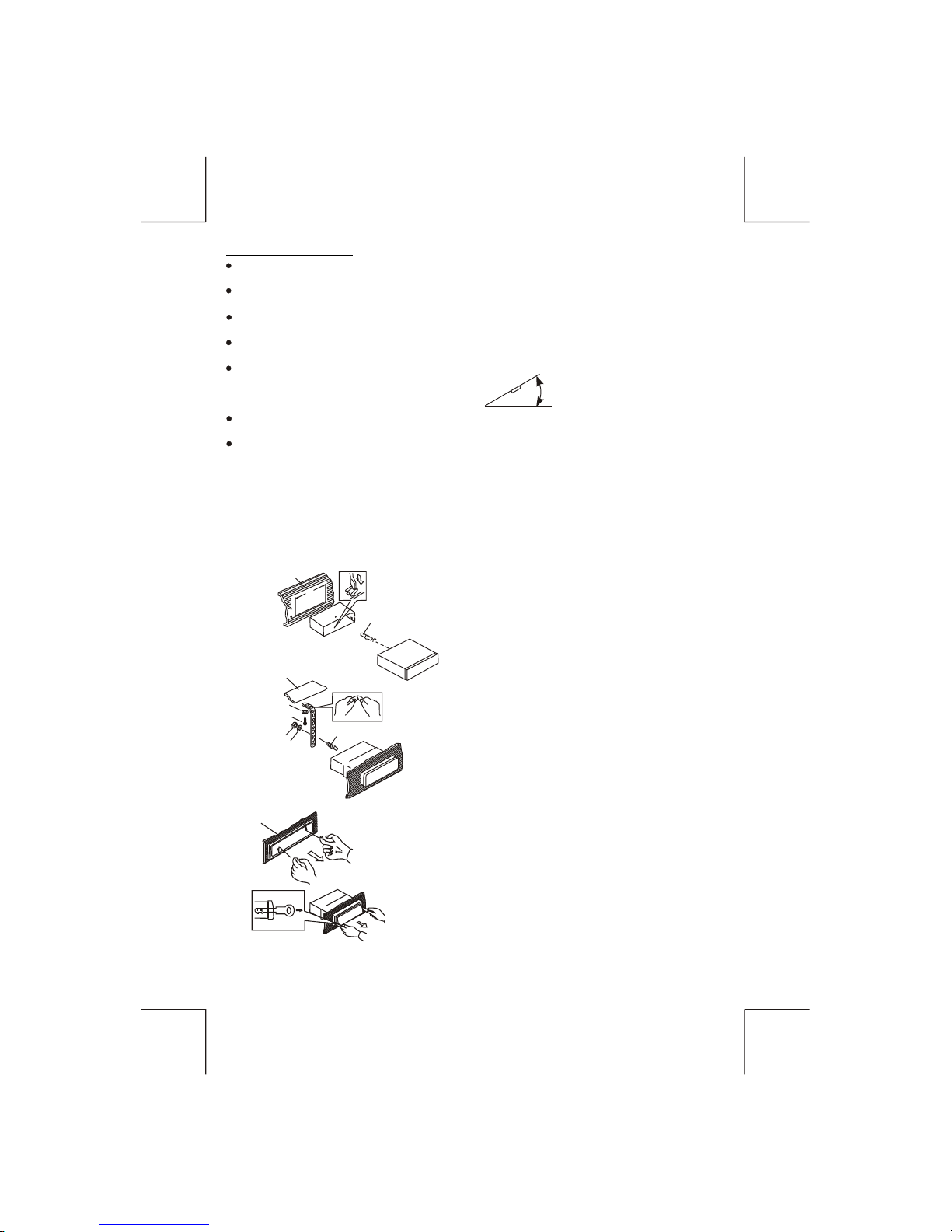
INSTALLATION
Before finally installing the unit, connect the wiring temporarily and make sure it is all connected up
properly and the unit and system work properly.
Use only the parts included with the unit to ensure proper installation. The use of unauthorized parts
can cause malfunctions.
Consult with your nearest dealer if installation requires the drilling of holes or other modifications of
the vehicle.
Install the unit where it does not get in the driver's way and cannot injure the passenger if there is a
sudden stop, like an emergency stop.
If installation angle exceeds 30° from horizontal, the unit might not give its optimum performance.
Avoid installing the unit where it would be subject to high temperature, such as from direct sunlight, or
from hot air, from heater, or where it would be subject to dust dirt or excessive vibration.
Be sure to remove the front panel before installing the unit.
DIN FRONT/REAR-MOUNT
This unit can be property installed either from “Front” (conventional DIN Front-mount) or “Rear”(DIN
Rear-mount installation, utilizing threaded screw holes at the sides of the unit chassis). For details, refer
to the following illustrated installation methods A and B.
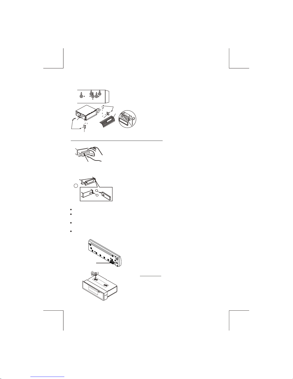
DIN FRONT-MOUNT (Method A)
Installation the unit
1. Dashboard
2. Holder
After inserting the half sleeve into the dashboard,
select the appropriate tab according to the
thickness of the dashboard material and bend
Them inwards to secure the holder in place.
3. Screw
30°
1. Dashboard
2. Nut (5mm)
3. Spring washer
4. Screw (5x25mm)
5. Screw
6. Support Strap
Be sure to use the support strap to secure the
back of the unit in place. The strap can be bent by
hand to the desired angle.
7. Plain washer
1
7
4
2
3
5
6
182
53
1
2
3
Removing the unit
a. Frame
b. Insert fingers into the groove in the front of frame
and pull out to remove the frame. (When
re-attaching the frame, point the side
with a groove down wards and attach it.)
c. Insert the levers supplied with the unit into the
grooves at both sides of the unit as shown in figure
until they click. Pulling the levers makes it possible
to remove the unit from the dashboard.
a
b
c
Trim Plate Installation:
Push the trim plate against the chassis until it is fitted.
You must do this before you install the front panel, otherwise it can't be attached.
GB - 3
DIN REAR-MOUNT (METHOD B)
Installation using the screw holes on the sides of the unit.
Fastening the unit to the factory radio mounting bracket.
1. Select a position where the screw holes of the
bracket and the screw holes of the main unit
become aligned (are fitted) and tighten the
screws at 2 places on each side.
2. Screw
3. Factory radio mounting bracket.
4. Dashboard or Console
5. Hook (Remove this part)
Note: the mounting box, outer trim ring, and half-
sleeve are not used for method B installation.
5
2
4
3
2
5
2. DETACHABLE CONTROL PANEL (D.C.P.)
Removing The Detachable Control Panel (D.C.P.).
1. Turn the power off
2. Press the D.C.P. release button
3. Remove the D.C.P.
PANEL RELEASE
BUTTON
B
A
2
Attaching the DCP
CAUTION
1. Attach the panel at the right side first, with point B
on the main unit touching point A on the D.C.P. (As
shown on the digram).
2. Then press the left side of D.C.P. onto the main unit
until a “click” sound is heard.
DO NOT insert the D.C.P from the left side. Doing so may damage it.
The D.C.P can easily be damaged by shocks. After removing it, place it in a protective case and
be careful not to drop it or subject it to strong shocks.
When the release button is pressed and the D.C.P is unlocked, the car's vibrations may cause it
to fall. To prevent damage to the D.C.P, always store it in a protective case after detaching it.
The rear connector that connects the main unit and the D.C.P is an extremely important part.
Be careful not to damage it by pressing on it with fingernails, pens, screwdrivers, etc.
Note:
If the D.C.P is dirty, wipe off the dirt with soft, dry
cloth only. And use a cotton swab soaked in
isopropyl alcohol to clean the socket on the back
of the D.C.P.
Socket
These 2 screws are used to prevent damage to the CD
mechanism during transportation Please make sure to
remove the 2 screws before installing the unit into the
vehicle. DO NOT insert a CD into the unit before removing
the 2 screws.
IMPORTANT
GB - 4
GB- 5
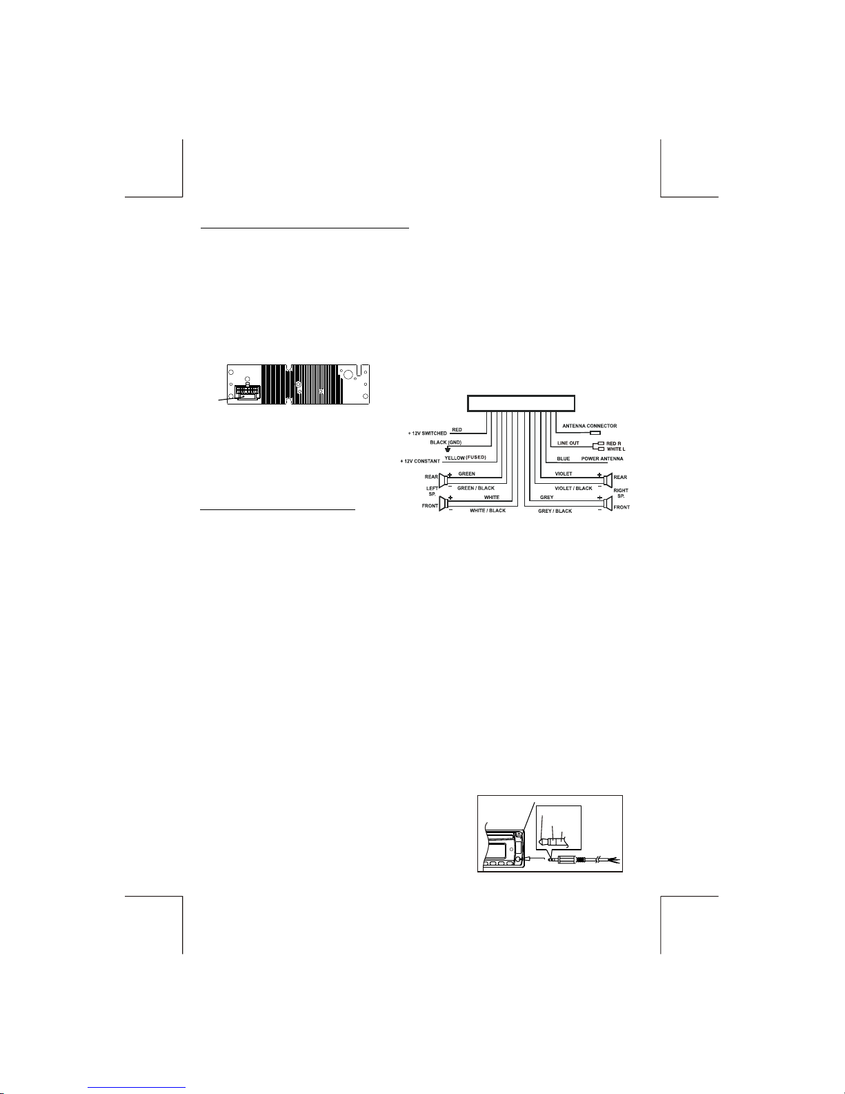
ELECTRICAL CONNECTION
a. Make sure your car battery is a 12 volt (6 filler caps) negative ground system (if not, a
converter will be necessary).
b. Before starting wiring connections, disconnect the power supply by removing the fuse from
the fuse box.
c. Connect the power wire to one of the extra terminals of the fuse box.
d. Connect the black ground wire to a metal part of the car. It is important to make good
contact.
e. Make other wiring connections as shown.
f. If your car does not have ISO connector, you can procure it from any car accessory shop.
Press this button to remove the control panel.
Press this button to turn on or off the power.
BASIC OPERATIONS
PANEL RELEASE BUTTON
POWER BUTTON
Notes: INCORRECT WIRING OR OPERATION WILL AVOID THE WARRANTY OF THIS UNIT.
Fuse Replacement:
To replace the fuse, pull out the blown fuse from the
socket. Insert a new one with same rating.
FUSE
(CAR UNIT BACK SIDE)
DISPLAY BUTTON
For RDS models:
Press this button to view other information such as clock , RDS information, band and
frequency ...etc.
FRONT CABINET
RIGHT TRACK
GROUND
AUX IN
LEFT TRACK
A) Tuner mode (Radio)
B) CDP/MP3 (only if a CD or Mp3 disc is inserted)
C) USB (only if a USB drive is inserted)
D) SD/MMC (only if a SD or MMC card is inserted)
E) AUX mode (only if this unit is equipped with this feature)
Whenever a USB or SD/MMC is being inserted, unit will automatically switch to USB or
SD/MMC mode, does not matter the unit is currently in what mode.
When in USB or SD/MMC mode, if the USB or SD/MMC is being removed, unit will
automatically switch to previous mode.
MODE BUTTON
Press this button to select different mode, sequence as follow:
MODE PRIORITY
FRONT AUX INPUT
Connect the external signal to the front 3.5mm earphone jack on front panel, then press Mode
button to select Aux mode. Press Mode Button again to cancel Aux Mode and return to
previous mode.
4 SPEAKER SYSTEM
 Loading...