

Page 1
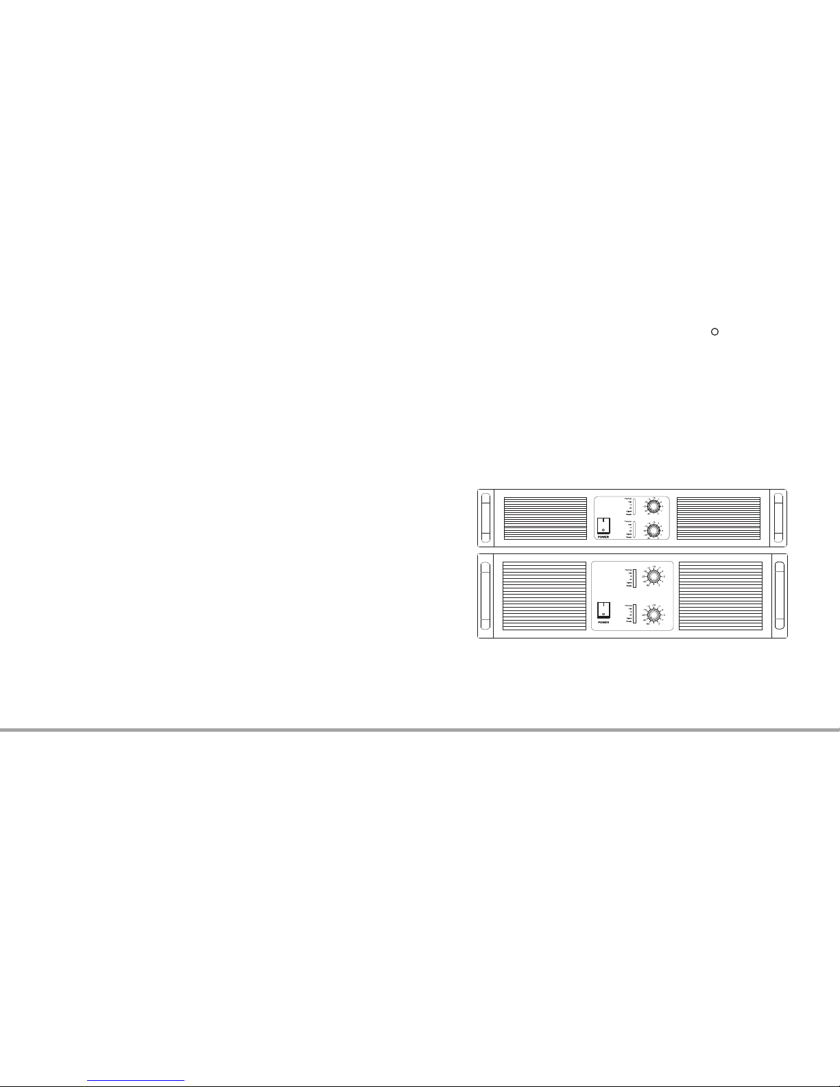
2 CHANNELS POWER AMPLIFIER
USER’S MANUAL
PROFESSIONAL POWER AMPLIFIER
TWO CHANNELS POWER AMPLIFIER
CLASS AB / CLASS H
CLASS AB / CLASS H
A SERIES
R
AUDIO MASTER
Page 2
Imp ortan t preca ution s and app licat ion ran ge
For eword
Pro duct br ief int roduc tion
Fro nt pane l funct ion int roduc tion
Rea r panel f uncti on intr oduct ion
Sys tem con necti on case s
Spe cific ation
Mal funct ion eli minat ion
CATALOGUE
1. Read these prescripts.
2. Keep this user manual
3. Pay attention to all the notice
4. Comply with these prescripts
5. Warming:to avoid causing fire or hit by the thunder,don't put the equipment in the rain or in the wet environment.
6. Wiped by dry cloth
7. Don't wall up the intake
8. Don‘t install near the heat headstream like radiator,heat adjust setting,camp stove etc.(including amplifier)
9. Don't make the grounded plug invalidation,this equipment should be connection to the plug through protective grounded plug.
10. Protect the wire from being trampled or extruded,especially the plug,power plug and the connector of it.
11. Please turn off the power amplifier power before take off the electronic wire,signal wire or to change the switching of input mode and cut the limiter.
12. Please use under suitable voltage remarked on the back panel. If the equipment is damaged because of using the wrong voltage,we will charge
from service.
13. If one signal is used in more than one power amplifiers,suggest using signal assigner.
14. Don‘t connect the output interface of one channel to the input interface of another channel in the power amplifier. Don’t connect one power amplifier
to another one by connecting their output in series or parallel connection.
15. To matching with the power amplifier,the power of the power amplifier should be 50%-100% more than the loudspeaker power.
16. When mend the power amplifier,don‘t connect the probe of the oscilloscope to the output interface under bridge in case of damaging the power
amplifier and the oscilloscope.
17. Please use the sequence power if more than one power amplifiers are used at the same time.
CATALOG TWO CHANNEL POWER AMPLIFIER
IMPORTANT PRECAUTIONS AND SIGN EXPLANATION
There are non-insulated parts with dangerous voltage,which can make people get an electricshock in the
equipment. So please don’t open the cover. If maintenance is needed,please ask the professional for repair
or return to the factory.
Warning:there is important information in this manual users. This product correct volt is 230.
TWO CHANNELS POWER AMPLIFIER
No sound, only with green “on” LED lighting.
Confirm if the gain control is turned on. Confirm if both ends of the input cable is installed correctly. Confirm if to check or connect other
amplifier to present sound source to check.
No sound but signal LED with slight light states that the amplifier has signal output,so sound shall be heard if connect the speaker. Use
other to check the connection of speaker.
No sound with PRT light on
When opening or closing, the amplifier is in temporary silence so as to avoiding acoustical shock. If amplifier is with serious over heat and
in silence as well, keep the amplifier as it is until it turns cool. The fans will run in full speed, but the sound will be recovered in a minute. If
the amplifier touches hot, and the fans don‘t work, maintenance for amplifier is required.
Amplifier drones
Balanced XLR cable is more suitable for long distance operation. If the unbalanced connection(signal-core cable) is adopted, drone may
be a problem since generally the signal-core leads in interference.
According to the different connecting type, drone may appear earlier in the signal chain. If the total power is not too large, it will benefit a lot
to make all plug in the same AC jumper.
Finally, moderate drone sometimes can be reduced throng decreasing amplifier gain and raising high source gain for compensation. But
the sound source must be guaranteed offering large enough sound so as not to cause over load distortion. If the drone isn’t reduced,
perhaps it is from sound source.
Below are the connections when power amplifier needs service:
1. Amplifier smoked or smelled burning.
2. Cabinet has severe indentation and deformation.
3. Amplifier are dipped into the liquid.
4. Internal components loosen
5. The circuit breaker on the rear panel skips out when current increases.
MALFUNCTION ELIMINATION
1
10
No response
Make sure that the AC cord is completely inserted in the socket with electricity. Try to use other equipment to test the AC power, like the lamp. Check
whether the power switch at the front panel is on or not. If yes, then the amplifier is in need of maintenance.
Amplifier loses voice
If the amplifier over loads too much, fans runs in full speed and increasing temperature will automatically reduces the circuitry and volume so as to
prevent mute error caused by overheat. After the input signal decrease appropriately, amplifier will return to normal gain in 1-2 minutes. The protect
light in the front panel turns off the maintenance is required.
Input of channel 2 seems of no avail.
Check whether the mode switch at the rear panel is at the stereo position. With parallel and bridge, input of channel 2 is of no avail.
Sensitivity for both channels is inconsistent
Make sure whether the setting of volume controller is consistent or not.(suggestion:turn the volume to 0 dB at the normal operation.) Make sure
whether the impendence of output speaker is consistent or not.
Amplifier sound is distorted
If the red CLIP LED is flashing, that means the amplifier works beyond the normal rated power. Clip circuit will appropriately reduce the volume to
avoid a serious overload, but if the input signal continues to increase, limiter may be crossed, resulting in increase distortion. If the speaker or the
speaker cable suffers short circuit or malfunction, and the loading is below the normal level, the amplifier will get distortion or no sound, and the red
clip LED light will flicker more, or the protect LED light will be on. The other speakers or cable should be used for inspection.
If impedance of each channel is less than 2 ohm, connecting too much speakers will be very easy to get the amplifier overload and burnt.
If the sound is distorted or not clear, but the red CLIP LED does not flicker, thus there is no distortion within the amplifier. Speaker may be damaged
or input signal gets distortion.
1. Use other equipment to check the whether the speaker is in good condition or not.
2. If the amplifier‘s gain control sets over low, it may lead to input over load and over-loaded operation of input source. Thus reduce the volume until
the distortion disappears, and raise the amplifier gain to idea level.
Generally, it is better to set the gain at the max level(0dB)or close to max level.
3. Check all input connection. Don’t connect two different sound source with the same channel. Suggest using mixer to mix the sound resource.
Page 3
Foreword
TWO CHANNELS POWER AMPLIFIER
Thank you very much for purchasing our products.
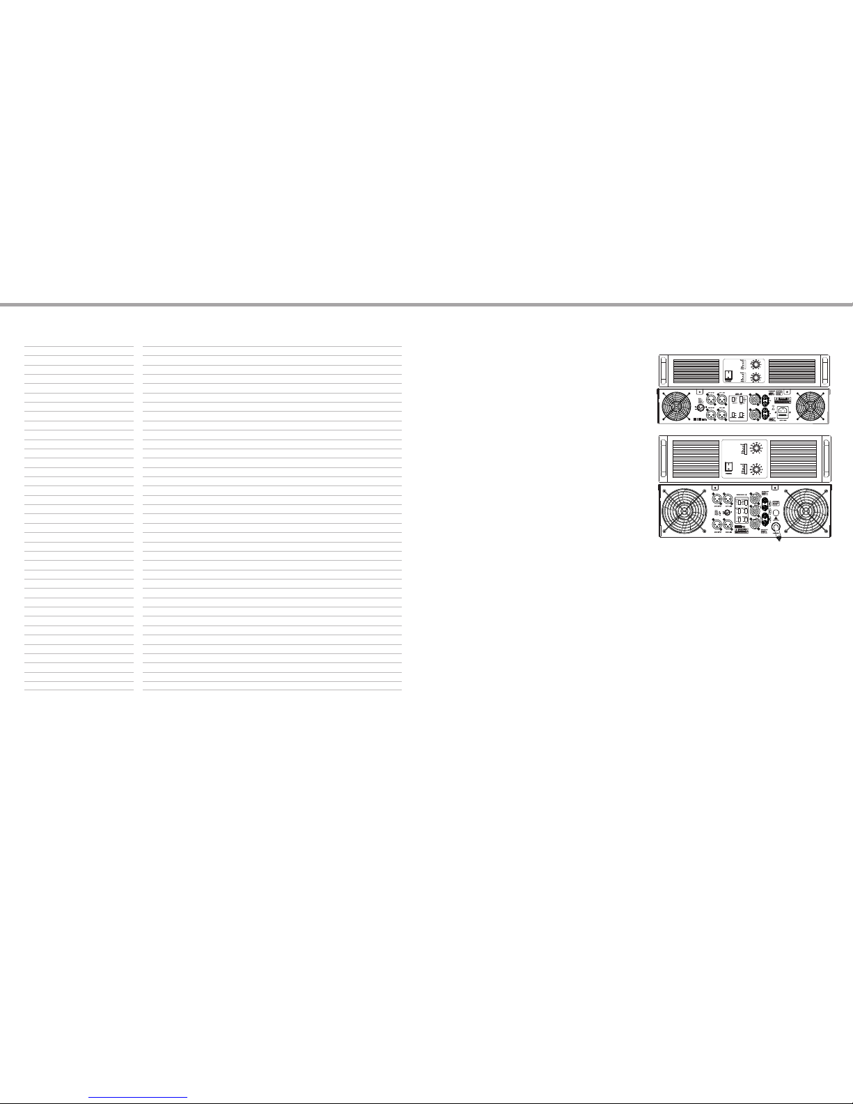
The two channels professional power amplifier made
from our patent technique Class H.
It is suitable for small scale performance,Karaoke room,
entertainment club, etc. In order to make better operation,
please read this manual carefully.
WELCOME
Please make sure if the appearance of the power amplifier
was damaged or not during the transportation after you
opened the package. Please make sure the preset voltage
is matched with your local AC voltage ( please check into
it on the real panel of the power amplifier ). We suggest you
retain in package in case you need them for further transportation.
TO UNCLOSE THE PACK
The design of products has already taken the safe requirement in
to consideration and all the finished products have been tested
under the requirement of the government before sale. Users should
read the notice in this manual before operation as there is dangerous
high voltage and electricity inter the products. It will increase the
change of getting shock by the electricity if the product falls down,
recess in the appearance,soaked or there were some parts loose
internal. If there are problems above,please turn off power immediately
and send the defective units to local distributor for service.
IMPORTANT PRECAUTION
INTRODUCTION TECHNOLOGY HIGHLIGHTS
SPECIFICATION
TWO CHANNELS POWER AMPLIFIER
2
9
Remark:
1. The power is tested under the condition of 40ms burst,1khz sine wave and 1% THD.
2. Other data is tested under CE / ROSH standard.
3. The power test marked with can‘t be used the power sine wave signal directly to test,or the DC insurance and other components may be broken.
4. The final specification is subject to the user manual.
Model
8 ohm stereo power**
4 ohm stereo power**
2 ohm stereo power**
8 ohm bridge power**
4 ohm bridge power**
Other specification
Frequency Response
THD+N
S/N Ratio
Slew Ratio
Damping Factor
Crosstalk
Input Sensitivity
Input impedance(balance/unbalance)
Voltage gain(sensitivity:8ohm)
Output Circuitry
Cooling
Protection
Connector
Input
Output
Indictor
Front panel
Rear panel
Dimension/weight
Product Dimensions (L*W*H)
Packing Dimensions (L*W*H)
G.W(±5KG)
Power cord
A1000 A1200 A1400
1000Wx2 1200Wx2 1400Wx2
1500Wx2 1800Wx2 2100Wx2
2250Vx2 2400Wx2 2800Wx2
3000W 3600W 4200W
400W 4800W 5600W
20Hz-20KHz±0.3dB
<0.05%@8Ω1KHz
>93dB
35V/µS
>800
>70dB@8Ω1KHz
0.775V/1.0V/1.4V
10KΩ/20KΩ
38dB
Class H Class H Class H
Air flow from front to rear
Soft start,DC, short circuit,over load,Clip limit,over heat,progressive volume
XLR-F,TRS,XLR-F,XLR-M
two red and black binding posts
Front panel indicator:signal,clip,protect,power indicator,bridge,parallel power switch,volume
control knob
Stereo / parallel / bridge switch,input sensitivity switch,low pass filter,high pass filter,
grounding switch
515*485*133(3U)
665*590*203
40KG 42KG 44KG
removable american 13A
AC110V/60HZ
AC230V/50HZ
Our professional power amplifier is adopted
stylish design integrated with new-launched high
performance Class H amplifier and analog
transformer power supply. It is designed for
Karaoke room. It adopts high sound quality power
transistor, with the characteristic of high
power efficiency and good sound.
Low noise figure, suitable for various occasions
Power soft start impact resistant, overload, overheat
protection, work well and reliable Input and output
signal comparison circuit, less chopped, clipping
limiting function to protect speaker system Frequency
sweep are accurate and natuarl to control
speaker system Stereo, bridge, multiple and
speakon caron socket input/output, then connect
speakers fast and reliably Working state of
positive LED light, easy to operation and adjust music.
Page 4
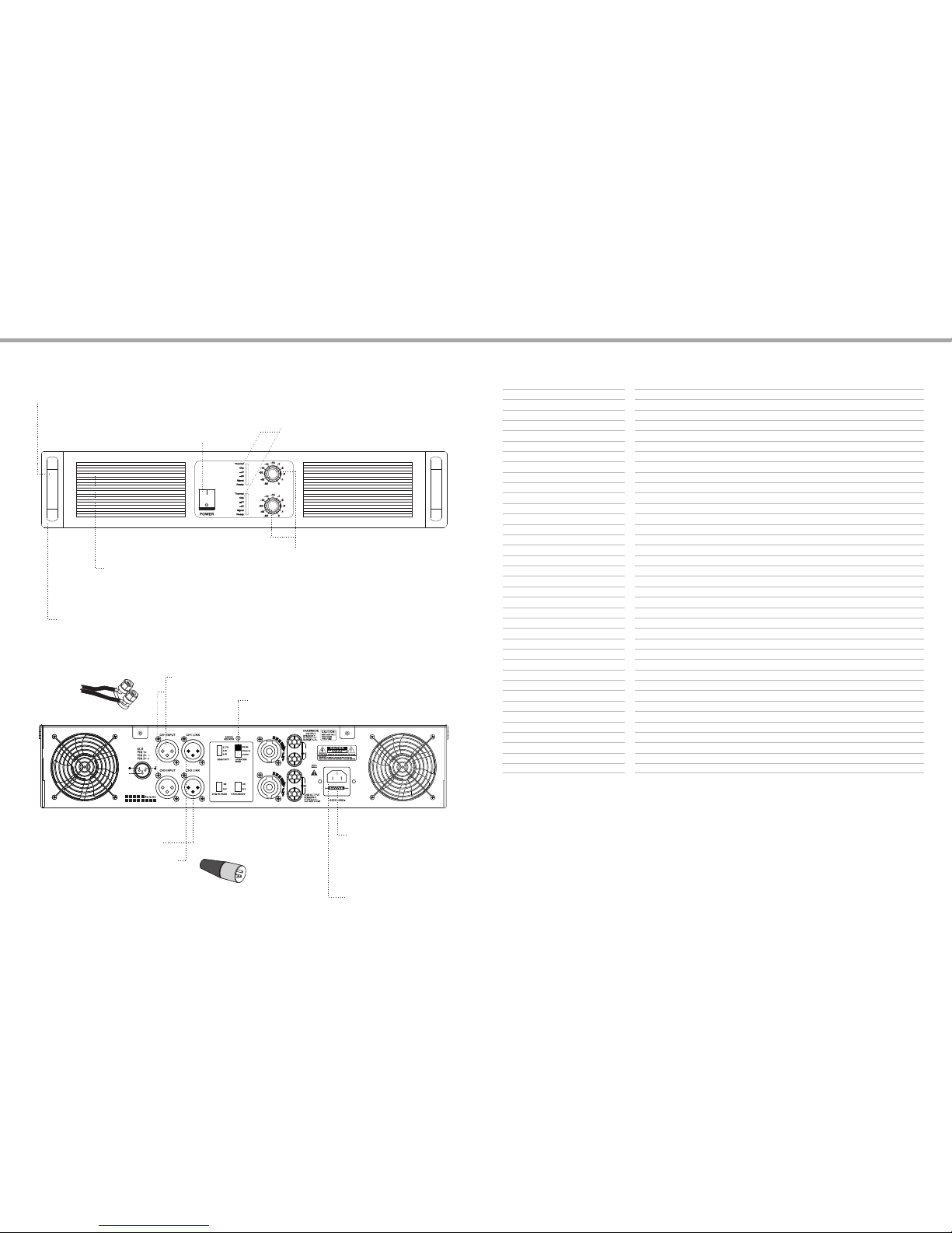
FRONT PANEL FUNCTION INTRODUCTION
FUNCTION INTRODUCTION OF FRONT PANEL
TWO CHANNELS POWER AMPLIFIER
Gai n contr ol
cha nnel 1, chann el 2 ,
Att enuat ion uni t state d:dB
For n ormal o perat ion,p lease k eep the
con troll er at max (0 db).
Ther mal-T he prot ected o verhe at
over load, short c ircui t,dc, softs tart
Read y-Ind icato r
ON-o pen sit uatio n
SIG- signa l indic ation
CLIP -clip i ndica tion
Int ake
Int er fan wi ll soak t he air fl ow from f rontt o rear.
If th e power a mplif ier is us ed with h eavy lo ad,
the f an will r un more q uickl y. Remova ble net work
mas k make it e asy to cl ean,p lease d on‘t bl ock the
int ake,c lean th e netwo rk mask r egula rly.
Han dle
Ins talla tion ho le
Ins tall st andar d 19“ca binet ,2U
BACK PANEL FUNCTION INTRODUCTION
Res torab le over -curr ent bre aker
220 v/240 v(15A )or 110v/ 120v( 20A)
Whe n there i s sudde n over cu rrent o r
sho rt circ uit in th e ampli fier,i t will
aut omati cally c ut the AC in put pow er.
Ple ase pre ss it aga in,af ter the
mal funct ion is se ttled .
AC in put
pow er cord s ocket
Bal ance XL R input
CH1 ,CH2, i nput co nnect ion
Fee t 2 conne ct posi tive po le
Fee t 3 conne ct nega tive po le
And f eet 1 con nects g round p ole
It is r ecomm ended t o adopt t his
Way fo r opera tion in l ong or sh ort
Dis tance b etwee n the amp lifie r and
sig nal sou rce.
Out put mod e selec tor swi tch
Cas e 1 for spe aker co nnect ion,B indin g posts ,
Nak ed cabl e or term inal, inser t into th e side ho le
TWO CHANNELS POWER AMPLIFIER
SPECIFICATION
3
8
A200 A400 A600 A800
250Wx2 400Wx2 600Wx2 800Wx2
375Wx2 600Wx2 780Wx2 1200Wx2
500Wx2 800Wx2 1200Wx2 1600Wx2
700W 1200W 1800W 2400W
1000W 1600W 2400W 3200W
20Hz-20KHz±0.3dB
<0.05%@8Ω1KHz
>95dB >95dB >95dB >93dB
35V/µS
>800
>70dB@8Ω1KHz
0.775V/1.0V/1.4V
10KΩ/20KΩ
38dB
Class AB Class H Class H Class H
Air flow from front to rear
Soft start,DC, short circuit,over load,Clip limit,over heat,progressive volume
XLR-F,TRS,XLR-F,XLR-M
two red and black binding posts
Front panel indicator:signal,clip,protect,power indicator,bridge,parallel power switch,volume
control knob
Stereo / parallel / bridge switch,input sensitivity switch,low pass filter,high pass filter,
grounding switch
500*485*88(2U)
599*568*155
20KG 22KG 24KG 28KG
removable american 13A
AC110V/60HZ
AC230V/50HZ
Model
8 ohm stereo power**
4 ohm stereo power**
2 ohm stereo power**
8 ohm bridge power**
4 ohm bridge power**
Other specification
Frequency Response
THD+N
S/N Ratio
Slew Ratio
Damping Factor
Crosstalk
Input Sensitivity
Input impedance(balance/unbalance)
Voltage gain(sensitivity:8ohm)
Output Circuitry
Cooling
Protection
Connector
Input
Output
Indictor
Front panel
Rear panel
Dimension/weight
Product Dimensions (L*W*H)
Packing Dimensions (L*W*H)
G.W(±5KG)
Power cord
Remark:
1. The power is tested under the condition of 40ms burst,1khz sine wave and 1% THD.
2. Other data is tested under CE / ROSH standard.
3. The power test marked with can‘t be used the power sine wave signal directly to test,or the DC insurance and other components may be broken.
4. The final specification is subject to the user manual.
Pow er swit ch
Page 5
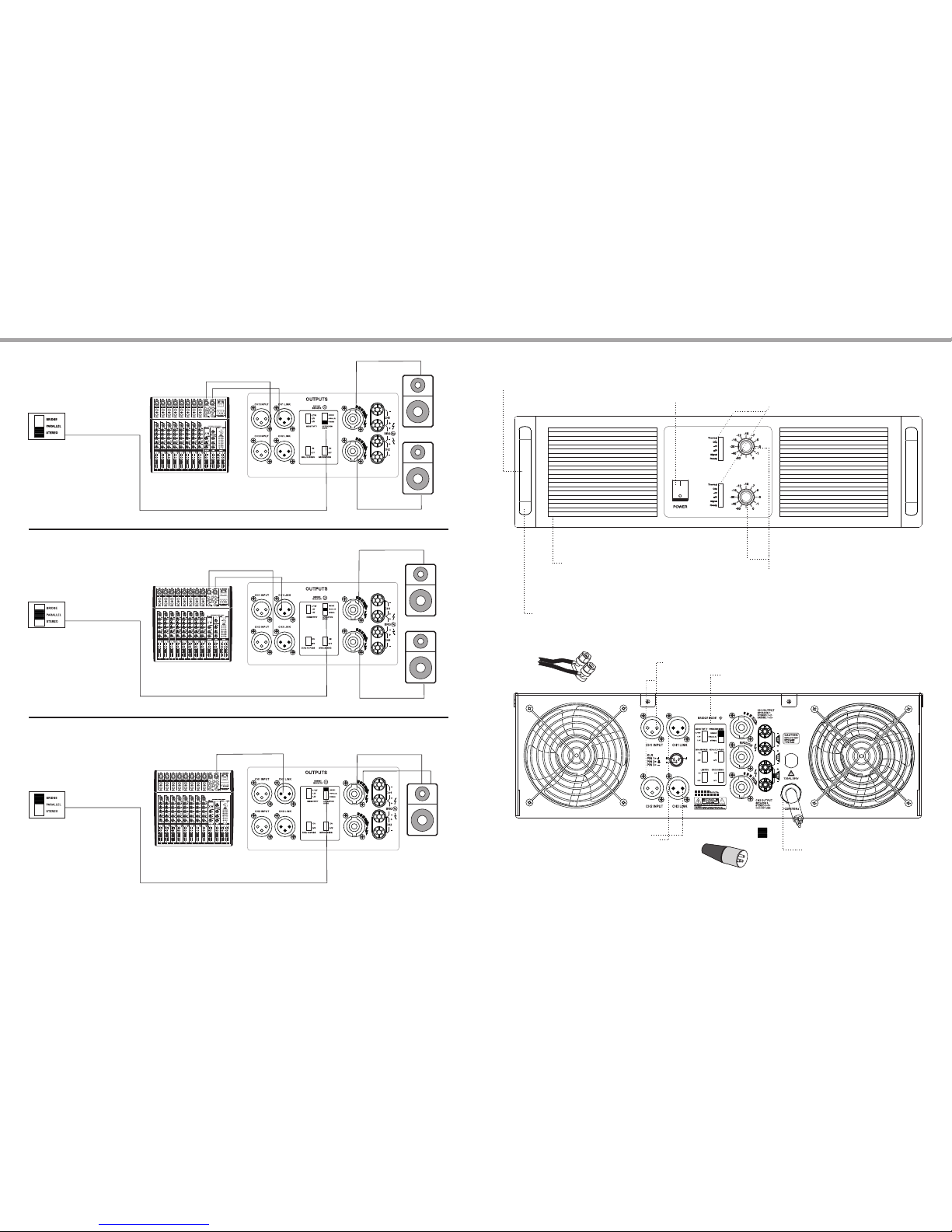
FRONT PANEL FUNCTION INTRODUCTION
TWO CHANNELS POWER AMPLIFIER
SYSTEM CONNECTION CASE 3
TWO CHANNELS POWER AMPLIFIER
4
7
Ste reo mod e
mov e mode sw itch to
ste reo pos ition
SYSTEM CONNECTION
INTRODUCTION
STEREO
Res pecti vely co nnect t he left
& rig ht sign al sour ce with C H1
and C H2.
The o utput t ermin als res pecti vely
con nect wi th a spea ker.
Par allel m ode
Mov e the mod e switc h to
par allel p ositi on.
PARALLEL
The o utput t ermin al of eac h
cha nnel
Res pecti vely co nnect s peake r
The o utput v olume o f each
cha nnel is c ontro lled by t he
vol ume kno b at the fr ont pan el.
Bri dge mod e
Mov e the mod e switc h to
bri dge pos ition .
BRIDGE
Con nect th e posit ive ter minal
of bo th chan nels to s peake rs.
The o utput v olume i s contr olled
by CH 1/CH3 v olume k nob at th e
fro nt pane l.
SPE AKON ca ron soc ket or te rmina l
Con necti on mode :+1+2 .
8/4 ohm
8/4 ohm
8/4 ohm
FUNCTION INTRODUCTION OF FRONT PANEL(3U)
Gai n contr ol
cha nnel 1, chann el 2 ,
Att enuat ion uni t state d:dB
For n ormal o perat ion,p lease k eep the
con troll er at max (0 db).
Ther mal-T he prot ected o verhe at
over load, short c ircui t,dc, softs tart
Read y-Ind icato r
ON-o pen sit uatio n
SIG- signa l indic ation
CLIP -clip i ndica tion
Int ake
Int er fan wi ll soak t he air fl ow from f ront to r ear.
If th e power a mplif ier is us ed with h eavy lo ad,
the f an will r un more q uickl y. Remova ble net work
mas k make it e asy to cl ean,p lease d on‘t bl ock the
int ake,c lean th e netwo rk mask r egula rly.
Han dle
Ins talla tion ho le
Ins tall st andar d 19“ca binet ,3U
BACK PANEL FUNCTION INTRODUCTION
AC in put
pow er cord s ocket
Bal ance XL R input
CH1 ,CH2, i nput co nnect ion
Fee t 2 conne ct posi tive po le
Fee t 3 conne ct nega tive po le
And f eet 1 con nects g round p ole
It is r ecomm ended t o adopt t his
Way fo r opera tion in l ong or sh ort
Dis tance b etwee n the amp lifie r and
sig nal sou rce.
Out put mod e selec tor swi tch
Cas e 1 for spe aker co nnect ion,B indin g posts ,
Nak ed cabl e or term inal, inser t into th e side ho le
+1
+2
Pow er swit ch
Page 6
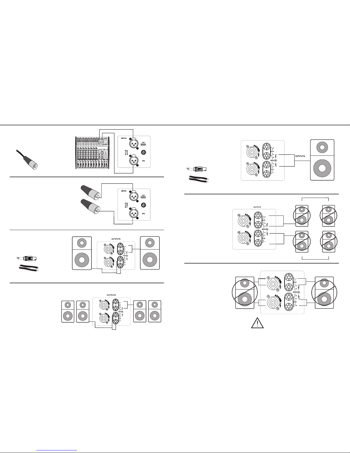
SYSTEM CONNECTION CASE 1 SYSTEM CONNECTION CASE 2
TWO CHANNELS POWER AMPLIFIERTWO CHANNELS POWER AMPLIFIER
Spe aker co nnect ion at br idge or p arall el outp ut
SPE AKON ca ron soc ket or te rmina l
Con necti on mode :+1+2 .
Wir ing
Wron g conne ction o f speak er 1
Wron g conne ction o f speak er 2
Don ’t conn ect the o utput t ermin als of bo th
cha nnels w ith the s ame spe aker!
8ohm
2oh m
2oh m
2oh m
2oh m
5 6
2
1
3
2
1
3
Inp ut conn ectio n
XLR m ixer
Bal anced c onnec tion
Fee t 2 to posi tive po le
Fee t 3 to nega tive po le
Fee t 1 to grou nding p ole
Unb alanc ed conn ectio n
Fee t 2 to posi tive po le &fee t 1 & feet 3 to n egati ve pole .
Thi s conne ction i s only ap plied f or shor t dista nce
tra nspor t betwe en ampl ifier a nd sign al sour ce,an d may
cau se nois e in diffe rent ap plica tion en viron ment.
(su ggest n o use)
Spe aker co nnect ion at st ereo or p arall el outp ut
SPE AKON ca ron soc ket or te rmina l
Con necti on mode :+1-1 .
Wir ing
Eac h chann el can re spect ively c onnec t
two 8 o hm spea kers.
Spe aker co nnect ion at st ereo or
par allel o utput .
8/4/2 o hm
8/4/2 ohm
8oh m
8oh m
8oh m
8oh m
 Loading...