

Audio Engineering Axium AX-400DA Instruction Manual
Axium AX-400DA
Multi-Zone Digital Amplifier
Instruction Manual

Important Safety Instructions
1 Read these instructions.
15 Unplug this apparatus during lightning storms or
when unused for long periods of time.
2 Keep these instructions
3 Heed all warnings
16 Never expose the unit to moisture
4 Follow all instructions
17 Refer all servicing to qualified service personnel.
Servicing is required when the apparatus has been
damaged in any way, such as power-supply cord or
plug is damaged, liquid has been spilled or objects
have fallen into the apparatus. The apparatus has
been exposed to rain or moisture, does not operate
normally, or has been dropped.
5 Do not use this apparatus near water
6 Clean only with dry cloth
7 Do not block any ventilation openings, Install in
accordance with the manufacturer’s instructions
8 Ensure that the ventilation is not impeded by
covering the ventilation openings with items such as
newspapers, table cloths, curtains, etc.
18 Damage requiring service
Unplug the apparatus from the wall outlet and
refer servicing to qualified service personnel under
the following conditions:
9 Do not install near any heat source such as
radiators, heat registers, stoves or other apparatus
(including amplifiers) that produce heat.
10 Use the apparatus only in moderate climates (not
in tropical climates).
A) When the power supply cord or plug is
damaged
11 Do not defeat the safety purpose of the polarized
or grounding type plug. A polarized plug has two
blades with one wider than the other. A grounding
type plug has two blades and a third grounding
prong. The wide blade or third prong is provided
for your safety. If the provided plug does not fit
into your outlet, consult an electrician for
replacement of the obsolete outlet.
B) If liquid has been spilled, or objects have
fallen into the apparatus.
C) If the apparatus has been exposed to rain or
water,
D) If the apparatus does not operate normally by
following the operating instructions. Adjust
only those controls that are covered by the
operating instructions as an improper
adjustment of other controls may result in
damage and will often require extensive work
by a qualified technician to restore the
apparatus to its normal operation.
12 Protect the power cord from being walked on or
pinched particularly at plugs, convenience
receptacles, and the point where they exit from the
apparatus.
13 Only use the attachments/accessories specified by
the manufacturer.
E) If the apparatus has been dropped or
damaged in any way, and
14 If you install the apparatus in a built-in installation,
such as a bookcase or rack, ensure that there is
adequate ventilation. Leave 20cm (8”) of free
space at the top and sides and 10cm (4”) at the
rear. The rear edge of the shelf or board above the
apparatus shall be set 10cm (4”) away from the
rear panel or wall, creating a flue-like gap for warm
air to escape. Good airflow is necessary to help
ensure proper operation. Not only should you
provide enough free space around the unit, but
also ensure that air can flow freely and escape
from the amplifier surroundings. Failure to do so
may cause thermal shutdown of the unit, and
reduced life expectancy.
F) When the apparatus exhibits a distinct change
in performance this indicates a need for a
service.
19
Object and Liquid Entry
Never push objects of any kind into the apparatus
through openings as they may touch dangerous
voltage points or short-out parts that could result
in a fire or electric shock.
The apparatus shall not be exposed to dripping or
splashing and no objects filled with liquids, such as
vases, shall be placed on the apparatus.
Don’t put candles or other burning objects on top
of this apparatus.
2

Precautions
1. AC Fuse - The AC fuse inside the unit is not user-
serviceable. If you cannot turn on the unit, contact
the dealer from whom you purchased this unit.
2. Care - Occasionally you should dust the unit all
over with a soft cloth. For stubborn stains, use a
soft cloth dampened with a weak solution of mild
detergent and water. Dry the unit immediately
afterwards with a clean cloth. Don’t use abrasive
cloths, thinners, alcohol, or other chemical
solvents, because they may damage the finish or
remove the panel lettering.
3. Power
WARNING
BEFORE PLUGGING IN THE UNIT FOR THE FIRST
TIME, READ THE FOLLOWING SECTION
CAREFULLY.
AC outlet voltages vary from country to country.
Make sure that the voltage in your area meets the
voltage requirements printed on the unit’s rear
panel. (e.g. AC 110V – 240V 50/60HZ)
The power cord is used to disconnect this unit from
the AC power source. Make sure that the plug is
readily operable (easily accessible) at all times.
If you do not intend to use the unit for an
extended period, remove the power cord from the
AC outlet.
4. Earth – The unit is defined as Class1 in EN60065
(low voltage directive) and MUST BE EARTHED.
Connect only to a mains socket outlet with
protective earth, and only use the power cord
supplied.
Finland:
“Laite on Liitettävä suojamaadoituskoskettimilly
varustettun pistorasiaan”
Norway:
“Apparatet må tilkoples jordet stikkontakt”
Sweden:
Apparaten skall anslutas till jordat uttag”
5. Never Touch This Unit With Wet Hands –
Never handle this unit or its power cord while your
hands are wet or damp. If water or any other
liquid gets inside this unit, have it checked by your
Axium dealer.
6. Handling Notes
• If you need to transport this unit, use the
original packaging to pack it how it was when
you brought it.
• Do not leave rubber or plastic items on this
unit for a long time, because they may leave
marks on the case.
• This unit’s top and rear panels may get warm
after prolonged use. This is normal.
• If you do not use this unit for a long time, it
may not work properly the next time you turn
it on, so be sure to use it occasionally.
7. Speaker Shorts
Under no circumstances should the speaker output
terminals of the unit be short circuited, grounded
or connected to another output.
8. Direct Sun light - Avoid installing the amplifier in
positions where the front panel is exposed to direct
sunlight – may cause control to become sluggish.
9. Controller Connection - Never connect more
than eight Axium controllers. The supply is
internally fused (self resetting) and may open
circuit. Never connect the unit’s 12VDC terminal
(‘Bus Run’ port) to an external power supply.
3

DECLARATION OF CONFORMITY
We declare under our sole responsibility that this
product, to which this declaration relates, is in
conformity with the following standards:
EN60065, EN55013, EN55020, EN61000-3-2 and
EN61000-3-3.
Following the provisions of Low Voltage Directive
2006/95/EC and EMC Directive 2004/108/EC, the
EC regulation 1275/2008 and its frame work
Directive 2009/125/EC for Energy-related
Products (ErP).
A NOTE ABOUT RECYCLING:
This product’s packaging materials are recyclable
and can be reused. Please dispose of any
materials in accordance with the local recycling
regulations.
When discarding the unit, comply with local rules
or regulations. Batteries should never be thrown
away or incinerated but disposed of in accordance
with the local regulations
concerning battery disposal.
This product and the supplied
accessories constitute the
applicable product according to
the WEEE directive.
For U.S. models
FCC information for User
CAUTION:
The user changes or modifications not expressly
approved by the party responsible for compliance could
void the user’s authority to operate the equipment.
Note: This equipment has been tested and found to
comply with the limits for a Class B digital device,
pursuant to Part 15 of the FCC Rules. These limits are
designed to provide reasonable protection against
harmful interference in a residential installation.
This equipment generates, uses and can radiate radio
frequency energy and, if not installed and used in
accordance with the instructions, may cause harmful
interference to radio communications. However, there
is no guarantee that interference will not occur in a
particular installation. If this equipment does cause
harmful interference to radio or television reception,
which can be determined by turning the equipment off
and on, the user is encouraged to correct the
interference by one or more of the following measures:
• Reorient or relocate the receiving antenna.
• Increase the separation between the equipment
and receiver.
• Connect the equipment into an outlet on a circuit
different from that to which the receiver is
connected.
• Consult the dealer or an experienced radio/TV
technician for help.
For Canadian Models
NOTE: THIS CLASS B DIGITAL APPARATUS COMPLIES
WITH CANADIAN ICES-003
For models having a power cord with a polarized plug:
CAUTION: TO PREVENT ELECTRIC SHOCK, MATCH
WIDE BLADE OF PLUG TO WIDE SLOT FULLY INSERT.
Modèle pour les Candadien
REMARGUE: CET APPAPEIL NUMRIQUE DE LA
CLASSE B EST CONFORME À LA NORME NMB-003 DU
CANADA.
Sur les modèles don’t la fiche est polarisée:
ATTENTION: POUR VITTER LES CHOCS
LECTRIQUES, INTRODUIRE LA LAME LA PLUS LARGE
DE LA FICHE DANS LA BORNE CORRESPONDANTE DE
LA PRISE ET POUSSER JUSQ AU FOND.
4

Supplied Accessories Table of Contents
Important Safety Instructions 2
Make sure you have the following accessories:
Precautions 3
Declaration of Conformity 4
Supplied Accessories 5
VDE CEE 7/7
European Plug
Schuko
Features 6
Front Panel Guide 8
Rear Panel Guide 9
to IEC60320
C13 socket
Typical System Configuration
10
Multiple Amplifier Stacks 12
Controller Termination 13
WEB Application 14
Axium Music Centre Program 17
RS232 Protocol 19
Specifications 22
AS3112
Australasian Plug
to IEC60320
C13 Socket
Axium CD
5

Features
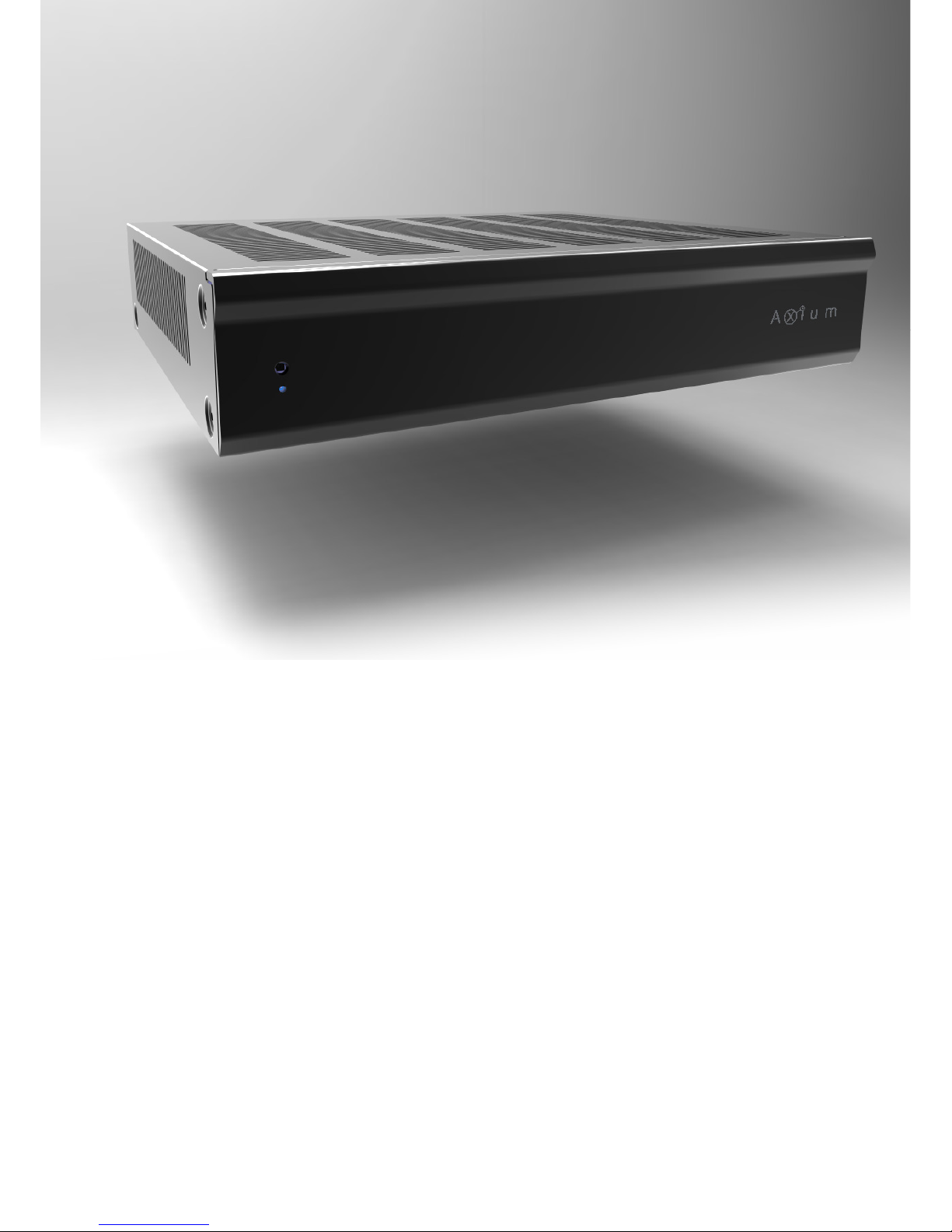
Thank you for purchasing an Axium AX-400DA Multi-Zone Amplifier.
Please read this manual thoroughly before making connections and plugging in the unit.
Following the instructions in this manual will enable you to obtain optimum performance and
listening enjoyment from your new Multi-Zone Amplifier.
Please retain this manual for future reference.
Multi-Zone, Multi-Source, Video Switching
The 400DA amplifier has four separate amplifiers
providing 4 zones of independent yet integrated
control.
There are 6 input sources comprising the
following:
Sources 1 – 3 are either Analog Stereo, or Coax
Digital Audio (PCM).
Sources 4 & 6 are Coax Digital Audio (PCM)
In addition there is a internally generated DoorBell source - .wav playback source - typically used
for paging applications.
Zone Outputs
Each zone has bass, treble, balance and loudness
control.
A feature called ‘Maximum Volume limiting’, is
useful for protecting connected speakers.
Amplifier Power, Protection, and Clipping
Indicators
50 Watts RMS per channel into 8 ohm loads.
Capable of driving into 4 ohm loads.
The amplifiers are protected against output
shorts, and have algorithms that prevent hard
clipping when the zone amplifiers are overdriven.
Thermal Control
There are two progressive levels of thermal
control:
• The amplifier volume is reduced 20dB.
• The amplifiers are shutdown until the
temperature reduces below the first level.
Care should be taken to ensure adequate
ventilation – see “Important safety instructions”
on page 1
Ethernet, RS232, USB and IR control
The 400DA amplifier may be controlled and
monitored via the rear Panel USB, RS232 serial
interface or Ethernet.
A Web application is available where full control
can be accessed using a suitable Web browser
running on a PC, Tablet or Smart Phone.
In multi amplifier installations where the
amplifiers are interconnected using an expansion
bus cable, only one Ethernet or RS232 connection
is required to control the stack of amplifiers.
The 400DA amplifier may receive IR directly from
the front panel receiver or via the four ‘Controller’
connections.
There are zone specific IR commands and also a
set of global IR commands.
The commands are: ON, OFF, Standby (toggling),
Mute, Volume Up, Volume Down, Source Selects,
Discrete Audio Source Selects, On with Source
Specific commands.
The Global commands also include PRESET1 –
PRESET 14, Alarm Enable, Alarm OFF, & 5 minute
Sleep.
Real Time Clock
The 400DA amplifier is equipped with a real time
clock.
The amplifier may be set up to function as an
alarm clock, so that at 6.30am in the morning 5
days a week, the master bedroom zone could be
made to turn on, select tuner, and go to a specific
volume. Multiple Alarms are feasible (max of 14)
however the Alarm Enable & OFF commands act
upon all programmed Alarms.
The Clock automatically compensates for daylight
saving.
The clock continues to operate typically > 48
hours without power – more than enough to keep
the time current during lengthy power outages
.
IR Emitter Ports
There are 8 Buffered IR emitter Ports.
Ports 1 – 6 have IR routing, and are intended to
control specific input source components. Two IR
ports; ‘SUM IR1-IR6’ are the sum of all IR sources
and control the ‘All’ zone source components.
6

Presets and Paging
There are 14 amplifier presets and two page
presets.
Presets 1 - 14 are momentary and cause the
amplifier to go to a predetermined setup, i.e.
standby, volume & source selection.
The presets may also be programmed with event
scheduling, and are used by the alarm clock.
The ‘Page Preset’ mode is for paging applications
and is invoked by a contact closure between the
0V and PG1 or PG2 terminals.
The contact closure must have an external power
source i.e. a 12 – 24V AC/DC powered door bell.
When the contact closure is released (power
sensed across PG – 0V terminals) the amplifier
zones return to their previous states.
PG1 is always assigned to the Page Preset.
PG2 may be assigned to any one of the 15
available Presets.
Zone Linking
A zone may be programmed to link multiple
zones. Zone linking ties the source selection
together. It may also tie the volume, and standby.
This is useful for closely coupled audio areas
where it is advantageous to have different volume
control but the same source, or the same volume
with separate standby control. Zone linking is
setup using the AMC program, or Web server
application.
96 Zones
There are 96 zones of possible control.
On a 400DAV amplifier each zone must be
different, however in a multiple amplifier stack
same zone amplifiers are possible – they simply
mimic every parameter.
Expansion Bus
Data, IR & Amp-On are interconnected via the
expansion bus.
One amplifier is connected to another using a
standard RJ45 patch cable. Connections are made
between amplifiers using either of the two RJ45
expansion bus sockets.
Door Bell
Up to 10 seconds of 44.1 KHz 16 Bit stereo
sounds may be generated as part of a page
preset. Suitable ‘wav’ files are uploaded to the
unit using the AMC program.
Amplifier ON Status – “Amp-On”
Each zone has AMP-ON status: 12VDC OUT on
the rear panel connector: (1, 2, 3, 4). The ‘AMP
ON’ output’s are protected against shorts.
Power Failure Restoration
After an AC power outage the 400DA amplifier
restores its settings to the pre-interrupted state.
All internal settings are stored in non-volatile
memory, except the clock that runs for at least 48
hours on stored power.
Restore Defaults
The 400DA amplifier may be readily set to the
default settings.
Restoring Defaults clears all memory and resets
the zone allocations to zones 1 – 4.
Setup Lockout
Locks access to the System Setup and More menus
where installation critical adjustments can be made.
Password = 1396
Firmware Upgradable
The 400DA amplifier may be updated with the
latest operational firmware, using the Axium
AMC program.
7
 Loading...