


Super Amp MKII
Stereo Vacuum Tube Power Amplifi er
Operation Manual
Before installing your new component, please read this manual carefully
as it will inform you of the specifi cations, proper installation and operation
procedures. Also included in this manual are guidelines on how to service
NOTE:
and care for your new Audio Electronics product.

TABLE OF CONTENTS
Important Safety Instructions ........................................................... 2-4
Welcome
Overview ...................................................................................................... 5
Unpacking and Installation .......................................................................... 6
Specifications
Basic Specifications ................................................................................... 7-8
Operation
AC On Power Switch .................................................................................... 9
Bias Measurement.........................................................................................9
The Break-In Period ....................................................................................10
Power Requirements...................................................................................10
Cables .........................................................................................................10
Controls & Displays
Front Panel ................................................................................................ 11
Rear Panel .................................................................................................. 11
Triode Operation Modification..................................................................... 12
Service and Care
Care and Cleaning ..................................................................................... 13
Tube Replacement...................................................................................... 13
Factory Service .......................................................................................... 13
Non-Warranty Repairs ............................................................................... 13
United States Limited Warranty .......................................................... 14
1

IMPORTANT SAFETY INSTRUCTIONS
WARNING: To reduce the risk of fire or electric shock, do
not expose this appliance to rain or moisture. The li g htning
flash with arrowhead symbol within an equilateral triang le i s
intended to alert the user to the presence of un-insulated
dangerous voltage within the product’s enclosure that may
be of sufficient magnitude to constitute a risk of electric
shock to persons.
CAUTION: To reduce the risk of electric shock, do not remove the cover. There are no user serviceable parts inside.
Please refer to qualified personnel for service.
ALERT: The exclamation point within an equilateral triangle is intended to alert the user of the presence of important
operating and maintenance (servicing) instruction s in the literature accompanying the component.
1. READ ALL INSTRUCTIONS: All the safety and operating instructions of your Audio Electronics equipment should
be read before power is applied to the equipment.
2. RETAIN OWNER’S MANUAL: These safety and operating instructions should be retained for future reference.
3. HEED WARNING: All warnings on the unit and in the operating instructions should be adhered to.
4. FOLLOW INSTRUCTIONS: All operating and use instructions should be followed.
5. CLEANING: Unplug the unit from the wall outlet before cleaning. The unit should be cleaned only as recommended
by the manufacturer.
6. ATTACHMENTS: Do not use attachments not recommended by the unit manufacturer as they may cause hazards.
7. WATER AND MOISTURE: Do not use the unit near water – for example, near a bath tub, wash bo w l, ki tchen
sink, or laundry tub; in a wet basement; or near a swimming pool.
8. ACCESSORIES: Do not place the unit on an unstable cart, stand, tripod, bracket, or table. The unit may fall,
causing serious injury to a child, an adult, or da m a ge to the unit. Mounting of the unit should follow the
manufacturer’s instructions and should use a mounting accessory recommended by the manufactur er.
9. VENTILATION: Slots and openin g s in the cabinet are provided for ventilation to ensure reliable operation of the
unit and to protect it from overheating. These openings must not be blocked or covered. The top or bottom panel
openings should never be blocked by placing the unit on a bed, sofa, rug, or other similar surface. The unit should
not be installed in a built-in location such as a bookcase or rack unless proper ventilation is provided. There should
be free space of at least 6 inches (16cm) above the unit and an opening behind the unit.
10. GROUNDING OR POLARIZATION: The unit may be equipped with a polarized alternating current line plug (a
plug having one blade wider than the other). This plug will fit into the power outlet only one way. This is a safety
feature. If you cannot insert the plug fully into the outlet, try reversing the plug. If the plug should fail to fit, contact
a licensed electrician to replace your obsolete ou tlet. Do not defeat the safety purpose of the polarized plug.
11. POWER SOURCES: The unit should be operated only from the type of power source indicated on the marking
label. If you are not sure of the type of power supplied to your home, consult your unit dealer or local power
company.
12. POWER CORD PROTECTION: Power supply cords should be routed so that they are unlikely to be walked on or
pinched by items placed on or against them. Pay close attention to cords where they enter a plug, or a convenience
receptacle, and the point where they exit from the unit.
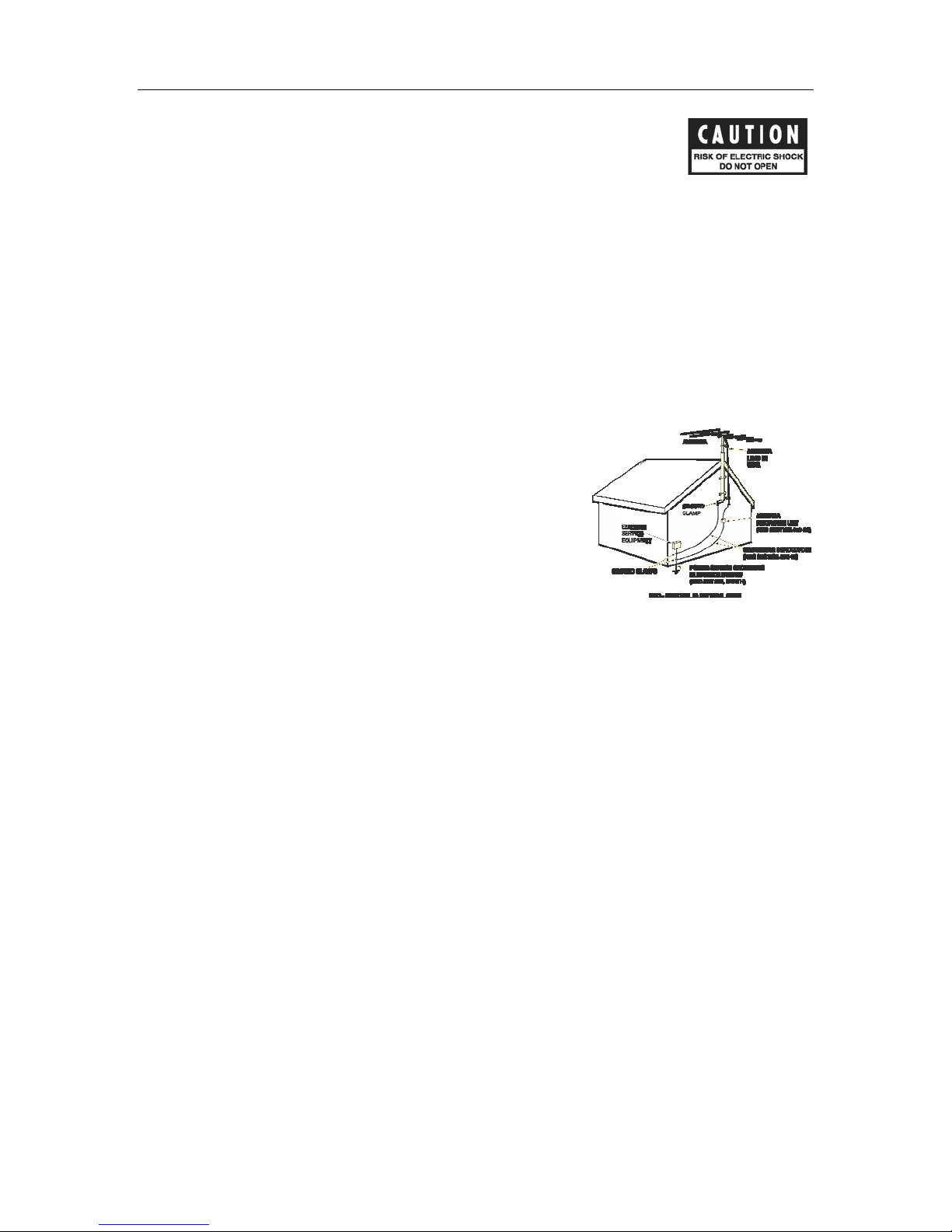
13. OUTDOOR ANTENNA GROUNDING:
antenna or cable system is grounded so as to provide protection against voltage surges and built-up static charges.
Article 810 of the National Electrical Code, NSI/NFPA 70, provides information regarding proper grounding of the
mast and supporting structure, grounding of the lead-in wire to an Antenna-discharge unit, size of grounding
conductors, location of antenna-discharge u nit, connection to grounding electrodes, and requirements for the
grounding electrode.
If an outside antenna or cable system is connected to the unit, be sure the
2

IMPORTANT SAFETY INSTRUCTIONS
14. LIGHTNING: For added protection for the unit during a lightning storm, or when it is left unattended and unused
for long periods of time, unplug it from the wall outlet and disconnect the antenna or cable system. This will prevent
damage to the unit due to lightning and power line surges.
15. POWER LINES: An outside antenna system should not be locat e d in the vicinity of overhead power lines or other
electric light or power circuits, or where it can fall into such power lines or circuits. When installing an outside
antenna system, take extreme care to keep from touc hing such power lines or circuits as contact with them might be
fatal.
16. OVERLOADING: Do not overload wall outlets, extension cords, or integral convenience receptacles as this can
result in a risk of fire or electric shock.
17. OBJECT AND LIQUID ENTRY: Never push objects of any kind into the unit through openings as they may touch
dangerous voltage points or short-out parts that could result in a fire or electric shock. Never spill liquid of any kind
on the unit.
18. SERVICING: Do not attempt to service the unit yourself as opening or removing covers may expose you to
dangerous voltage or other hazards. Refer all servicing to qualified service personnel.
19. REPLACEMENT PARTS: When replacement parts are required, be sure the service technician has used
replacement parts specified by the manufacturer or have the same characteristics as the original part. Unauthorized
substitutions may result in fire, electr ic shock or other hazards.
20. SAFETY CHECK: Upon completion of any service or repa irs t o the unit, ask the service technician to perform safety
checks to determine that the unit is in proper operating condition.
21. WALL OR CEILING MOUNTING: The unit should be mounted to a wall or ceiling only as recommended by the
manufacturer.
22. HEAT: The unit should be situated away from heat sources such as radiators, heat registers, stoves, or other units
(including amplifiers) that produce heat.
23. IMPORTANT SAFETY NOTE: Before connecting a new component to your audio or home theater system it is
always good practice to make certain tha t all components are turned off, and preferably unplugged from their AC
power source. Many modern electronics products feature automatic turn-on circuits that may be activated during an
installation, causing the potential for damag e to electronic components and/or speakers. Such damage is not
covered by product warranties and Audio Electronics specifically disclaims responsibility for any such damage.
Power Cord: The removable power cord that is shipped with the player is specifically designed to be used with this
product. Other AC cords may be used, so consult your dealer for advice on AC power cords and high quality wire in
your system.
compliance with, and listing by the UL, CSA or other standards required by the UL, CSA, NEC or your local building
code. Questions about cables inside of walls should be referred to a qualified custom installer, or a licensed
electrician or low-voltage contractor.
Do Not Open the Cabinet: There are no user serviceable components inside this product. Opening the cabinet
may present a shock hazard, and any modification to the product will void your warranty. If water or any metal
object, such as a paper clip, coin, or staple accidentally falls inside the unit, disconnect it from the AC power source
immediately and contact Audio Electronics for further instructio ns.
24. RECORDING COPYRIGHT: Recording of copyrighted material for other than personal use is illegal without
permission of the copyright holder.
25. NOTE TO CATV SYSTEM INSTALLER: This reminder is provid ed to call the CATV system installer’s attention to
article 820-40 of the NEC, ANSI/NFPA 70, which provides guidelines for proper grounding and, in particular, specifies
that the cable ground shall be connected to the grounding system of the building, as close to the point of cable entry
as practical.
AC Fuse: The fuse is located inside the chassis and is not user serviceable. If power does not
come on, contact your authorized service representative.
Wiring: Cables that run inside of walls should have the appropriate markings to indicate
3
IMPORTANT SAFETY INSTRUCTIONS
26. FCC INFORMATION FOR USER:
CAUTION: ANY changes or modifications not expressly approved by the party responsible
for compliance could void the user’s authority to operate the equipment.
NOTE: This equipment has been tested and found to comply with the limits for a Class B digital device pursuant to
Part 15 of the FCC Rules.
These limits are designed to provide reasonable protection against harmful interference in a residential installation.
This equipment generates and can radiate radio frequency energy and, if not installed and used in accordance with
the instructions, may cause harmful interference to radio communications. However, there is no guarantee that
interference will not occur in a particular installation. If this equipment does cause harmful interference to radio or
television reception, which can be determined by turning the equipment off and on, the user is encouraged to try to
correct the interference by one or more of the following measures:
- Reorient or relocate the receiving antenna.
- Increase the separation between the equipment and receiver.
Connect the equipment into an outlet on a circu it different from where the receiver is connected.
27. OUTDOOR ANTENNA INSTALLATION/SAFE ANTENNA AND CABLE
CONNECTION: If an outside antenna or cable system is connected to
the equipment, be sure the antenna or cable system is grounded so as to
provide protection against built up static charges and voltage surges,
Section 810 of the national Electrical Code, ANSI/NFP A70 (in Canada,
part 1 of the Canadian Electrical Code) provides information with respect
to proper grounding of the mast and supporting structure, grounding of
the lead-in wire to an antenna discharge unit, size of grounding
conductors, location of antenna discharge unit, connection to grounding
electrodes and requirements for the grounding electrode.
Keep Antenna Clear of High Voltage Power Lines or Circuits
An outside antenna system should be located well away from power lines, electric light or power circuits and where
it will never come into contact with these power sources if it should happen to fall. When installing an outside
antenna, extreme care should be taken to avoid touching p ow e r li nes, circuits or other power sources as this could
be fatal. Because of the hazards involved, anten na installation should be left to a professional.
4

WELCOME
OVERVIEW
Dennis J. Had, the founder and president of Cary Audio Design, speaks about the new Audio
Electronics Super Amp MKII amplifier design.
Dear Audiophile Friend:
I am so pleased and excited about the new Audio Electronics Super Amp MKII stereo
amplifier. I have spent countless hours designing and refining this very special vacuum tube
amplifier.
On numerous occasions, my business partner, Billy Wright, warned me that we did not want
to jeopardize the success of the highly acclaimed Super Amp stereo amplifier. “Are you sure
you can deliver the same sweet and intoxicating sound of the original Super Amp?” I was
also hearing from the field that the Super Amp maybe one of the best sounding amplifiers of
all time. Some audio magazine reviewers were stumbling over descriptive words for the Super
Amp. “At $1200, the Super Amp is beyond comparison.”
I must confess that the first renditions of the new Super Amp MKII did not come up to the
sonic greatness of the original Super Amp. This was going to be a tough effort to produce a
sonic presentation equivalent to the lower powered (12 watt) triode class A Super Amp. As
soon as you change a basic design to produce more power, the end result many times is
more power but at a cost of the sonic merits. In retrospect, I believe this challenge forced me
to take a more conservative time frame approach. I mean, when I get excited about a
conceptual product, I am flat out day and night designing. I can hardly wait to listen and in
turn, get the product into production.
The new Super Amp MKII started life in March of 2006. The design goal was to offer a 40
watt per channel Super Amp, operating in a class A/B push-pull ultra-linear design. Another
design goal was to offer a sensitive input drive level to allow passive line level control of a CD
player input. Of course the new matching AE-3 MKII active preamplifier is the best sonic
match for the Super Amp MKII.
I soon discovered this new design would call for a complete redesign of the input drive circuit
along with a new output transformer design. I also wanted to give this new baby a fresh new
look. Well to speed things up… I completed the new design in November of 2006. Does the
new Super Amp MKII meet and beat the original Super Amp? You bet!!!! I love it, and I
believe you will as well.
Enjoy the music in your home with your new Super Amp MKII.
God Bless you and your family.
Dennis
Each Audio Electronics Super Amp MKII is designed for long term stability in virtually any home
operating situation. However, if the unit is operated outside the parameters outlined in this
owner’s manual, damage may result. Please read this manual carefully before putting your new
component into operation.
5

WELCOME
UNPACKING AND INSTALLATION
This section describes the unpacking and installation procedures for your new component.
Unpacking
All Audio Electronics shipping cartons have been specially designed to protect their contents and
special care has been taken to prevent damage under normal shipping conditions. Mishandling
should be evident upon inspection of the shipping container. If shipping damage is found after
visual inspection, take care not to destroy the evidence. If necessary, document the damage with
photographs and contact the transport carrier immediately.
Carefully remove your new component from its packing carton and examine it closely for signs of
shipping damage. We strongly recommend saving all original packing cartons to protect your
component from damage should you wish to store it or ship it at a later date.
Warranty Card
If you are the original purchaser of this unit and you purchased it in the United States, you
should fill out the enclosed warranty registration card and return it to Audio Electronics within 15
days of your purchase. Audio Electronics also suggests that you keep your original packing
cartons in case you ever need to ship the unit when moving to a new home. Warranty
restrictions apply. Consult the warranty section of this manual for details. Please be certain to
keep a copy of the original sales receipt from your Authorized Audio Electronics dealer to validate
the warranty if ever needed.
6

SPECIFICATIONS
The following section describes the Super Amp MKII basic specifications. The specifications are
subject to change without notice or obligation.
BASIC SPECIFICATIONS
...........................................................................................................................................................................
Circuit Type Push-Pull Class AB Ultra-linear
Class A/AB Triode push-pull (simple mod)
...........................................................................................................................................................................
Power Output 40 Watts – Ultra-linear
20 Watts – Triode (mod kit included)
...........................................................................................................................................................................
Input Sensitivity 1 volt for full output
...........................................................................................................................................................................
Noise and Hum 80 dB below rated output
...........................................................................................................................................................................
Frequency Response 15 Hz to 50,000 + 0-3.0dB at one watt output
...........................................................................................................................................................................
Tube Compliment 1 – 6SN7 Input Tube
2 – 6SN7 Driver Tubes
4 – EL-34 Output Tubes
...........................................................................................................................................................................
Transformers 1 – EI laminated core power transformer
2 – Special bi filar wound output transformers
1 – High voltage filter choke
200% duty cycle on all transformers
...........................................................................................................................................................................
Resistors 1% metal film resistors
...........................................................................................................................................................................
Audio Capacitors Kimber Kap coupling caps
...........................................................................................................................................................................
Power Supply Capacitors 2 – 560 MFD @ 400VDC
1 – 47 MFD @ 450VDC
...........................................................................................................................................................................
AC Cord 3 conductor 16 gauge, detachable
...........................................................................................................................................................................
AC Power Requirements 115 volts AC 50/60 Hz 200 watts operate
230 volts AC 50/60 Hz 200 watts operate
...........................................................................................................................................................................
Warm-Up Time 3 minutes
...........................................................................................................................................................................
Break-in Period 100 hours of music playing time
...........................................................................................................................................................................
Finish Black powder coat with silver silk screen
Optional: Any Jaguar color automotive finish with clear coat
...........................................................................................................................................................................
Weight 42 lbs.
...........................................................................................................................................................................
Dimensions 7” H x 9” W x 15 ¼” D
...........................................................................................................................................................................
Special Note: The amplifier circuit runs at low enough voltage in the Super Amp
MKII that it can use the following output tubes: 6L6, 6V6, EL-34, 6CA7, KT-66, KT-77,
KT-88, KT-90 or 6550. The EL-34 tubes are standard.
7

SPECIFICATIONS
The Super Amp MKII optional features include:
• 4 – 51 ohm 3 watt triode resistors (included with initial shipment)
• 4 – KT-90 output vacuum tubes
• 4 – .22/600 VDC Audio One oil and film coupling caps
• 1 – Analog 0-200 ma. Bias adjustment meter
• 4 – Soft shoe isolation feet
• Custom automotive clear coat paint colors
8

OPERATION
Your new Super Amp MKII is ready for operation after the speaker, interconnect cables and tubes
have been installed.
amplifier located next to the output binding posts. The interconnect cables from the output of the
preamplifier can be any convenient length your set-up requires. The choice of a high quality
interconnect cable is important. Once again, your audio dealer will have the proper cables in
stock for this purpose.
AC ON POWER SWITCH
Rotate the AC power switch to the right. The amplifier will turn ON, and the blue and red LED’s
will light. The B+ voltage along with appropriate bias voltage will power up. The blue LED is an
indication of filament voltage and the red LED is an indication the B+ plate voltage is operating.
BIAS MEASUREMENT
Your new Super Amp MKII has come from the factory with pre-adjusted bias setting. Since all AC
wall outlet voltages vary according to location, you need to check and/or reset the tube bias
current. This is a simple procedure using the supplied bias jack cord set that came with your
Super Amp MKII.
An analog or digital multi-meter is required to perform this test and setting.
Signal input connection is made via the input jack on the rear of the
PLEASE NOTE
THE TEST METER MUST BE IN THE DC MA. CURRENT POSITION! FAILURE TO USE
THE DC CURRENT READING WILL RESULT IN DAMAGE TO THE OUTPUT TUBES
BECAUSE OF IMPROPER READINGS!
Follow the steps listed below.
Initial bias check: Plug the ¼” male bias plug into the rear apron bias jack. Hook the red
alligator clip to the positive test lead of a digital or analogue test meter. Hook the black alligator
clip to the negative test probe of the meter. Make sure the meter is in the DC CURRENT range.
This is very important… if the meter is set in the DC voltage position the reading will be
completely wrong. Please check and double check to make sure you are in DC current mode.
Turn on the Super Amp MKII with the front panel AC power switch. As the amplifier warms up
you will notice the DC current readings. The basic operation range should be 200 ma. DC cur r ent
after five minutes of operation. This value will vary plus or minus 10 to 15 ma. with changing AC
wall socket voltages. This is normal and does not change the basic performance of your Super
Amp MKII.
Bias Adjust: Use a conventional flat blade screw driver to rotate the bias adjustment pot on the
rear of the Super Amp MKII. Turning the pot to the right (clockwise) will increase the bias current
setting. Turning the pot to the left (counter clockwise) will decrease the bias current setting.
New Tube Bias: When replacing output tubes or simply “tube rolling” with different types of
output tubes please start the bias procedure as above with the initial setting of the bias pot in
the full counter clockwise (left) position. This is the zero (0) bias setting. After the amplifier has
warmed up for a few minutes rotate the bias pot slowly in a clockwise direction to the 200 ma.
setting on a DC current meter.
9

OPERATION
THE BREAK-IN PERIOD
The tubes, capacitors and output transformers take approximately 100 hours of music playing to
fully settle in for peak performance. The Super Amp MKII will sound good when first out of the
box. After the first couple of hours you will notice increased depth and tighter bass. This break in
period is true with vacuum tube audio amplifiers as the tubes finish their “burn in” cycle in the
first 100 hours of use.
WARNING!
MAKE SURE THE COMPONENT IS UNPLUGGED FROM AC MAINS BEFORE SERVICING.
POWER REQUIREMENTS
The Super Amp MKII is designed to operate from house current mains. The design voltage is 115
VAC at 50/60 Hz. (Foreign units 230 VAC at 50/60 Hz.)
CABLES
The speaker cables from the output posts of the Super Amp MKII to the speaker system can be
any convenient length your set-up requires. Select speaker cables of sufficient size to preserve
the outstanding performance capabilities of your Super Amp MKII. Heavy gauge #16 wire is
suitable for distances up to 10 feet; #12 for 25 feet. Most audio dealers will have proper speaker
cable in stock for this purpose.
10

CONTROLS & DISPLAYS
FRONT PANEL
POWER ON/OFF SWITCH
• Turn the AC power switch to the right to turn the Super Amp MKII ON.
REAR PANEL
OUTPUTS
• The 5-way speaker binding posts provide the output to the speaker system.
(Red = + Positive, Black = - Negative).
• Bare wire, banana plugs or spade lugs may be used. Do not over tighten the connection.
INPUTS
• Signal input connection via shielded RCA interconnect cable.
TUBE FUSE (Bias Circuit)
• Cathode current output tube fuse. Never replace with any other fuse than a ½ Amp
Fast Blow type fuse.
BIAS JACK
• ¼ inch 2 conductor plug for measuring DC current in the bias circuit.
AC POWER
• 3 conductor power cord supplied. After market cables may be also be used.
AC POWER FUSE
• Use only 3 Amp slow blow for 115 volt units.
• Use 2 Amp slow blow on 230 V export versions.
BIAS ADJUST
• Potentiometer to adjust bias current of EL-34 output tubes (200 ma. +
10-15 mA).
11

CONTROLS & DISPLAYS
CAUTION
USE OF ANY OTHER INCORRECT VALUE PROTECTION FUSE CAN DAMAGE THE UNIT.
CAUTION
NEVER REMOVE OR INSERT THE AC POWER LINE CORD WHEN THE UNIT IS
TURNED ON.
TRIODE OPERATION MODIFICATION
If you would like to have an even more lifelike performance from your Super Amp MKII you may
wish to strap the MKII in the triode mode. If your loudspeakers are in the range of 87 dB
sensitivity or more then the triode mode should give you plenty of power in a home listening
environment. Simply look to the following enclosed pictures and follow the simple unsoldering
and soldering steps.
The conversion from ultra-linear to triode operation of the Super Amp MKII is straight forward.
Important! Before removing the bottom cover, make sure that ALL tubes are removed.
1) Make sure the Super Amp
MKII is unplugged!
2) Remove the bottom cover by
unscrewing the Phillips screws.
3) Locate the blue/white wires
leading to pin #4 of the output
tubes sockets.
4) Unsolder this blue/white lead
from each channel tube socket.
5) Use the enclosed heat shrink
and cover the end of each of
these leads.
6) Locate the brown/white wires
leading to the other output tubes
socks and unsolder these leads
from pin #4.
7) Same as above, place the heat
shrink over the bare ends of the
leads and heat with a hair dryer
or a heat gun.
8) Solder the four (4) 51 ohm/3
watt resistors (one each tube
socket) between pin #3 and #4
as shown in the pictorial drawing.
9) Check your work and replace
the bottom plate on the amplifier.
12

SERVICE AND CARE
CARE AND CLEANING
The cabinet housing and front panel of this unit may be cleaned with a soft cloth and Windex or
a window cleaner. The frequency of cleaning will be governed by how many hours the
component is operated and by operating environment cleanliness. Deluxe paint finishes are easily
cleaned with a feather duster. Do not use acetone to clean the finish or it will remove the labels.
TUBE REPLACEMENT
If it becomes necessary to replace the tubes in the amplifier, a matched set of output tubes of
the same name brand should be used. A new tube kit is available from Audio Electronic Supply.
You should get a few years or more from the output tubes with everyday usage and many years
of use from the smaller tubes.
FACTORY SERVICE
Careful consideration has been given to the design of this component to keep maintenance
problems to a minimum. Any problems or requests for service should be referred to our
Customer Service Department at 919-355-0010. DO NOT return the unit to the factory without a
return authorization number (RA) from the Customer Service Department.
Audio Electronics will assume no responsibility if the shipping company refuses to pay for damage
due to your improper packing or lack of insurance should the unit be lost or damaged in
shipment. Please retain and always use the original shipping carton for shipping the player.
NON-WARRANTY REPAIRS
Audio Electronics will provide repair service for its products charging on a time and expense
basis. At this time, the standard non warranty service bench fee is $125 with all parts used for
repair charged extra. This may change and is not a quote for service. Please call us at 919-3550010 for more information about out of warranty service and repair fees.
WARNING!
MAKE NO ATTEMPT TO PUT THE SUPER AMP MKII IN SERVICE WITH THE BOTTOM
PLATE REMOVED - CONTACT WITH THE HIGH VO LTAGES FOUND INSIDE THE
CHASSIS CAN BE FATAL!
COMPLETELY REMOVE THE AC PLUG FROM THE WALL AND ALLOW 30 MINUTES FOR
THE HIGH VOLTAGE CAPACITORS TO DISCHARGE THROUGH THE BLEEDER
RESISTORS BEFORE ATTEMPTING TO CHANGE THE TUBES.
CAUTION
Never remove or insert the back panel AC plug when the unit is on or the AC cord is
plugged into the wall.
13

UNITED STATES LIMITED WARRANTY
Audio Electronics warrants to the original United States purchaser for use in the United States that this
product shall be free from defects in parts or workmanship for three (3) years from the date of the original
purchase. This is a limited warrant, for the original purchaser only and does not transfer to any subsequent
owner.
During the limited warranty period, Audio Electronics will provide free of charge both parts and labor
necessary to correct any defects in material or workmanship.
To obtain such warranty service, the original purchaser must:
1. Complete and send in the warranty Registration Card within 15 days of purchase.
2. Notify Audio Electronics as soon as possible after the discovery of a possible defect and submit the
following information to determine eligibility for warranty:
(a) The model number and serial number;
(b) A fully filled in copy of the original sales receipt showing the original selling price, purchasers
name and address filled in by an AUTHORIZED AUDIO ELECTRONICS DEALER with the original
date of purchase shown on the form;
(c) a detailed description of the problem.
3. Deliver the product to Audio Electronics or the nearest authorized service facility or ship with all
freight and insurance charges prepaid, in its original packing container or equivalent, to Audio
Electronics.
Correct maintenance, repair and use are important to obtain performance from this product. Therefore,
please carefully read the Operating Manual. This warranty does not apply to any defect that Audio
Electronics in its sole discretion determines is due to:
1. Improper maintenance or repair, including the installation of parts or accessories that do not
conform to the quality and the specifications of the original parts.
2. Misuse, abuse, neglect or improper installation.
3. Accidental or incidental damage.
WARRANTY DISCLAIMER
Except for the express warranties stated herein, Audio Electronics disclaims all other warranties including,
without limitation, all implied warranties of merchantability and fitness for a particular purpose. The
foregoing constitutes Audio Electronics’ entire obligation with respect to this product, and the original
purchaser and any user or owner shall have no other claim for incidental or consequential damages. Some
states do not allow the exclusion or limitation of incidental or consequential damages, so the above
limitation and exclusion may not apply to you. This warranty gives legal rights and you may also have other
rights, which vary from state to state.
EXCLUSIVE REMEDY
Notwithstanding the foregoing, the purchaser’s exclusive remedy for any breach of warranty, express or
implied, is limited to the repair or replacement of the defective unit or the refund of the purchase price, at
the option of Audio Electronics. Under no circumstances is Audio Electronics liable for incidental or
consequential damages. Any implied warranties imposed by law terminate one (1) year from the date of
purchase.
INTERNATIONAL PURCHASERS (Export markets)
Audio Electronics warrants its merchandise to purchasers within the United States exclusively for use within
the United States of America. It provides no other warranties, expressed or implied. If you are living
outside the USA, please consult with your local dealer or distributor to determine the details of your local
warranty.
14
 Loading...