


OWNER’S
Hercules
MANUAL
Power Amplier
NOTE: Before installing your new component, please read this manual
carefully as it will inform you of the product specications, proper
installation and correct operating procedures for your unit. Also included
in this manual are guidelines on how to service and care for your new
Audio Electronics product.

TABLE OF CONTENTS
Important Safety Instructions ............................................................................................................2
Welcome
Thank You ..........................................................................................................................................4
Specifications
Basic Specifications..............................................................................................................................5
Features
Product Features .................................................................................................................................6
Controls and Displays
Front Panel .........................................................................................................................................7
Rear Panel ..........................................................................................................................................8
Installation
Unpacking ..........................................................................................................................................9
Warranty Card ....................................................................................................................................9
Placement ........................................................................................................................................ 10
Operation
Turn on Sequence ............................................................................................................................. 11
Turn off Sequence ............................................................................................................................. 11
Power Switch .................................................................................................................................... 11
Selector Switch ................................................................................................................................. 11
Volume Control ................................................................................................................................. 11
Power Requirements .......................................................................................................................... 11
Cables .............................................................................................................................................. 11
Service and Care
Care and Cleaning ............................................................................................................................. 12
Tube Replacement............................................................................................................................. 12
Factory Service.................................................................................................................................. 12
Non-Warranty Repairs ........................................................................................................................ 12
Troubleshooting Guide ...................................................................................................................... 13
Diagrams
Tube Placement Chart........................................................................................................................ 14
Limited Warranty ............................................................................................................................... 15

IMPORTANT SAFETY INSTRUCTIONS
2
WARNING: The triangle with the lightning flash symbol
displayed on the unit advises the user of dangerous uninsulated voltage inside the product’s enclosure.
CAUTION: To reduce the risk of electric shock, do not
remove the cover. There are no user-serviceable parts
inside; it is recommended that only qualified personnel
service this component.
ALERT: The triangle with the exclamation point symbol on the component suggests that the owner refer to important
operating and maintenance instructions in the owner’s manual.
1. OWNER’S MANUAL: Before powering up the equipment, read all safety and operating instructions and follow them as
instructed. Retain the safety and operating instructions for future reference.
2. ATTACHMENTS: Use only those attachments recommended by the unit manufacturer, as others may cause hazards.
3. ACCESSORIES: Do not place the unit on an unstable cart, stand, tripod, bracket, or table. The unit may fall, causing
injury to a person or damage to the unit. Mount the unit according to the manufacturer’s instructions with the
suggested mounting accessory.
4. WALL OR CEILING MOUNTING: Mount the unit to a wall or ceiling only in the manner recommended by the
manufacturer.
5. WATER AND MOISTURE: Do not use the unit near water (for example, near a swimming pool, bath tub, wash bowl,
kitchen sink, or laundry tub) or in a damp environment (like a basement or outside in the rain).
6. OBJECT AND LIQUID ENTRY: Do not push objects of any kind into the unit through openings as they could touch
dangerous voltage points and short-out parts, possibly resulting in a fire or electric shock. Avoid spilling liquid of any
kind on the unit. If water or any metal object (such as a paper clip, coin, or staple) accidentally falls inside the unit,
disconnect it from the AC power source immediately and contact Cary Audio Design for further instructions.
7. HEAT: Position the unit away from heat sources such as radiators, heat registers, stoves, or other units (including
amplifiers) that produce heat.
8. VENTILATION: Slots and openings in the cabinet create ventilation to protect the component from overheating. These
openings on the top and bottom panels must remain unobstructed. Allow at least 6 inches (16cm) of clearance above
the unit and an opening behind the unit for airflow. Do not place the unit on a bed, sofa, rug, built- in bookcase, or
rack without adequate ventilation.
9. GROUNDING OR POLARIZATION: As a safety feature, the unit may be equipped with a polarized alternating
current line plug in which one blade is wider than the other. This plug will fit into the power outlet only one way. If you
cannot insert the plug fully into the outlet, try reversing the plug. If the plug still will not fit, contact a licensed
electrician to update your obsolete outlet. Do not defeat the safety purpose of the polarized plug.
10. POWER SOURCES: Operate the unit only from the power source indicated on the marking label. If you are unsure of
the type of power supplied to your home, consult your unit dealer or local power company.
11. POWER CORD PROTECTION: Arrange power supply cords so that they do not suffer from foot traffic or pinching by
items placed on or against them. Pay close attention to cords where plug enter the AC outlet and where they exit from
the unit.
12. LIGHTNING: For added protection during a lightning storm or when the component is idle for long periods of time,
unplug the unit from the wall outlet and disconnect the antenna or cable system. This will help protect the unit from
lightning and power line surge damage.
13. POWER LINES: Do not locate an outside antenna system in the vicinity of overhead power lines or other electric light
or power circuits. When installing an outside antenna system, take extreme care to avoid touching the power lines or
circuits; contact with them could be fatal.
14. OVERLOADING: Do not overload wall outlets, extension cords, or integral convenience receptacles as this increases
the risk of fire or electric shock.
15. REPLACEMENT PARTS: When replacement parts are required, be sure the service technician has used
replacement parts specified by the manufacturer or those having the same characteristics as the original parts.
Unauthorized substitutions may result in fire, electric shock or other hazards.
16. SAFETY CHECK: Upon completion of any service or repairs to the unit, ask the service technician to perform
safety checks to ensure the unit is in proper operating condition.
IMPORTANT SAFETY INSTRUCTIONS
3
17. IMPORTANT SAFETY NOTE:
18. RECORDING COPYRIGHT: Recording of copyrighted material for other than personal use is illegal without
19. NOTE TO CATV SYSTEM INSTALLER: This reminder is provided to call the CATV system installer's attention to
20. FCC INFORMATION FOR USER:
21. OUTDOOR ANTENNA INSTALLATION/SAFE ANTENNA AND CABLE CONNECTION:
Before connecting a new product such as the Cinema 12 to your audio or home theater system, turn off all
other equipment (preferably unplugging them from the AC power source). Many audio components feature
automatic turn-on circuits that may activate during an installation, potentially causing damage to electronic
components and/or speakers. This type of damage is not covered by product warranties, and Cary Audio
specifically disclaims responsibility for any such damage.
Power Cord: The removable power cord provided with your unit was specifically designed
for use with this product, but other AC cords may be used. Consult your dealer for advice
on AC power cords and high quality wire in your system.
AC Fuse: The fuse is located inside the chassis and is not user serviceable. If the unit does not power up,
contact an authorized service representative
Wiring: Cables running inside walls should have the appropriate markings to indicate compliance and listing
by the UL, CSA or other standards required by the UL, CSA, NEC or your local building code. Questions
about cables inside of walls should be referred to a qualified custom installer, a licensed electrician, or lowvoltage contractor.
permission of the copyright holder.
article 820-40 of the NEC, ANSI/NFPA 70, which provides guidelines for proper grounding and, in particular,
specifies that the cable ground shall be connected to the grounding system of the building as close to the point of
cable entry as practical.
CAUTION: Any changes or modifications not expressly approved by Cary
Audio Design could void the user's authority to operate the equipment.
NOTE: This equipment has been tested and found to comply with the limits for a
Class B digital device pursuant to Part 15 of the FCC Rules.
These limits are designed to provide reasonable protection against harmful interference in a residential
installation. This equipment generates and can radiate radio frequency energy, and if not installed and used
in accordance with the instructions it may cause harmful interference to radio communications. However,
there is no guarantee that interference will not occur in a particular installation. If this equipment does
cause harmful interference to radio or television reception, which can be determined by turning the
equipment off and on, the user is encouraged to try to correct the interference by one or more of the
following measures:
Reorient or relocate the receiving antenna.
Increase the separation between the equipment and receiver.
Connect the equipment into an outlet on a circuit different from where the receiver is connected.
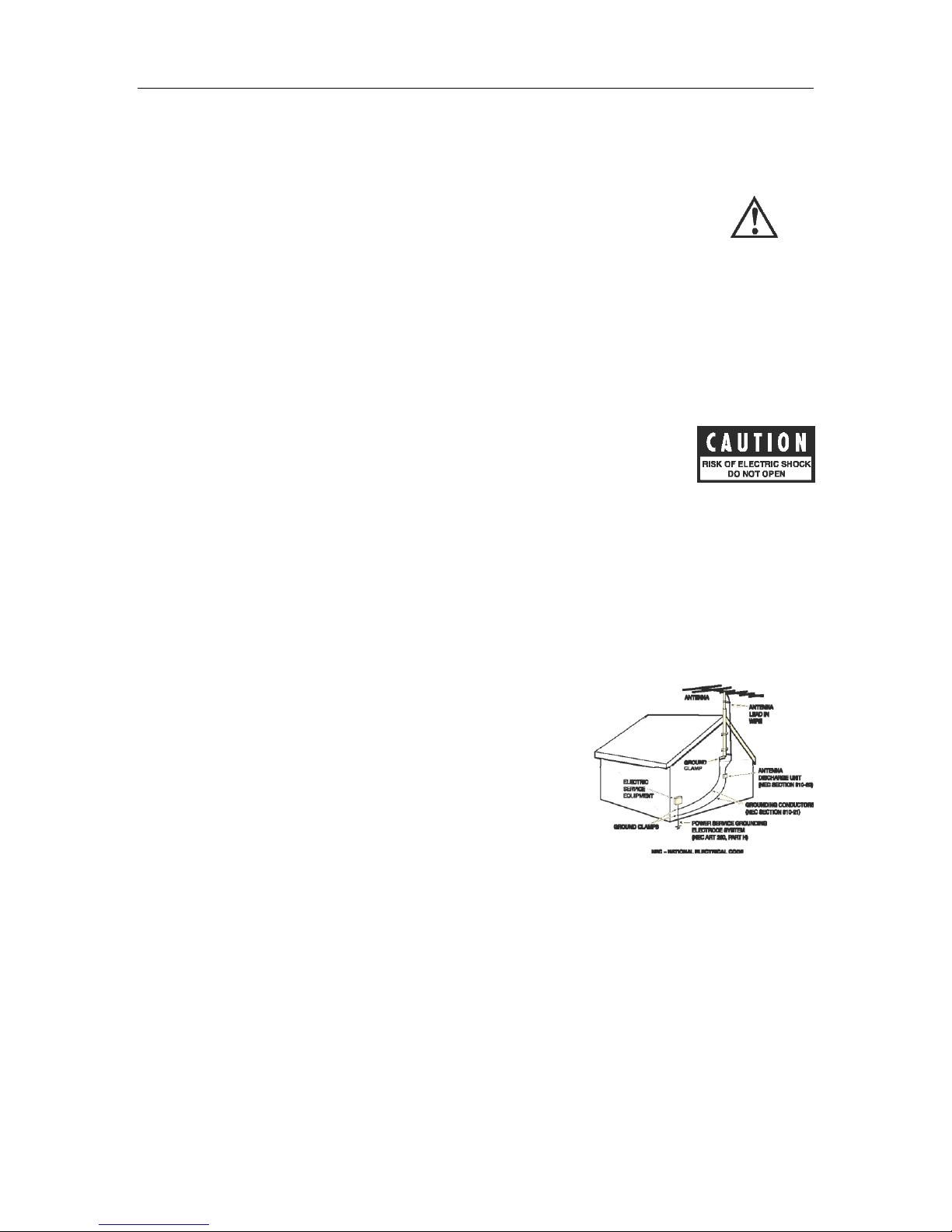
If an outside antenna or cable system is connected to the
equipment, be sure the antenna or cable system is grounded in
order to provide protection against built-up static charges and
voltage surges. Article 810 of the National Electrical Code,
ANSI/NFPA 70 (in Canada, Part 1 of the Canadian Electrical
Code) provides information regarding proper grounding of the
mast and supporting structure, grounding of the lead-in wire to
an antenna discharge unit, size of grounding conductors,
location of antenna discharge unit, connection to grounding
electrodes and requirements for the grounding electrode.
Outside antenna system should be located well away from
power lines, electric light or power circuits and where it will
never come into contact with these power sources if it should
happen to fall. When installing an outside antenna, extreme
care should be taken to avoid touching power lines, circuits or
other power sources as this could be fatal. Because of the hazards involved, antenna installation should be
left to a professional.

WELCOME
4
THANK YOU
Thank you for purchasing the new Hercules power amplifier from Audio Electronics by Cary Audio!
Cary Audio has a long history of providing the high-end community true audiophile sound quality
with its award winning line of tube and solid state amplification and digital products for audio and
cinema systems. Through Audio Electronics, Cary Audio’s subsidiary originally created in 1993 and
now re-launched, a new segment of music lovers is about to be wowed. While Cary Audio has an
established reputation with the seasoned audiophile, Audio Electronics is positioned to reach a new
generation of music fans with a smaller, sleeker design suited for the modern environment.
By providing a contemporary design and excellent sound quality in lower price-point products,
Audio Electronics is promoting the future of the high-performance audio industry while preserving
the heritage and integrity of the Cary Audio brand.
Thanks again for your support of our products.

SPECIFICATIONS
5
The following section describes the Hercules amplifier’s basic specifications. The specifications
are subject to change without notice or obligation.
BASIC SPECIFICATIONS
................................................................................................................................................
Input Impedance 150K ohms
................................................................................................................................................
Gain 26dB
................................................................................................................................................
Frequency Response 15Hz – 20KHz
................................................................................................................................................
Power Output 30 watts ultra-linear
................................................................................................................................................
Signal to Noise Ratio -91dB
................................................................................................................................................
Feedback Zero
................................................................................................................................................
Sensitivity .8V
................................................................................................................................................
Tube Complement 2 – 12AX7 input and driver
4 – EL34 output
................................................................................................................................................
Output Impedances 4K or 8K
................................................................................................................................................
Input Power Requirements 117V or 220V 50-60Hz
................................................................................................................................................
Power Consumption Operate: 165 watts
................................................................................................................................................
Dimensions 13” L X 14.25” W X 7.5” H
................................................................................................................................................
Weight 45 lbs.
................................................................................................................................................

CONTROLS AND DISPLAYS
6
The following section describes the Hercules amplifier’s basic features. The features are subject
to change without notice or obligation.
PRODUCT FEATURES
The Hercules power amplifier is an ultra linear tube amplifier using EL34 output tubes to produce
30 watts per channel. Boasting premium components, it features a very simple signal path to
provide sonic purity and long-term reliability. The Hercules uses a specially built power supply
combined with custom output transformers to allow the amplifier to be heavily biased into Class-A
while providing excellent bass and transient response.
The differentially-balanced input section reduces noise, and a cathode-bias function assures you of
the best possible performance from your tubes at all times and allows the amplifier to run in
Class-A over a larger power range. An automatic mute/standby circuit ramps up the voltage to the
tubes gradually for longer life; it also removes any pops or noise at turn-on. This attention to detail
and the elegantly simple circuit design offers a musically accurate and satisfying amplifier offering
truly high-end performance at real world pricing.

CONTROLS AND DISPLAYS
7
FRONT PANEL
1. POWER
Press once to turn the power ON. The power indicator will blink for twenty (20) seconds
Press again to turn the power OFF.
and then stay on, at which point the unit is ready to operate.

CONTROLS AND DISPLAYS
8
REAR PANEL
1. INPUT
Left Input (top)
Right Input (bottom)
2. FUSE
Tube Fuse Right (1/4 amp)
3. OUTPUT
Positive Right Output
4. OUTPUT
Negative Right Output
5. OUTPUT
Positive Left Output
6. OUTPUT
Negative Left Output
7. FUSE
Tube Fuse Left (1/4 amp)
8. AC POWER
AC Fuse (3 amp, Slow-Blow)
Attach the correct power cord for country of use. This should be supplied with the unit.

INSTALLATION
9
UNPACKING
This section describes the proper unpacking and installation procedures for your new
component.
Unpacking
All Audio Electronics shipping cartons have been specially designed to protect their contents and
special care has been taken to prevent damage under normal shipping conditions. Mishandling
should be evident upon inspection of the shipping container. If shipping damage is found after
visual inspection, take care not to destroy the evidence. If necessary, document the damage with
photographs and contact the transport carrier immediately.
Carefully remove your new component from its packing carton and examine it closely for signs of
shipping damage. We strongly recommend saving all original packing cartons to protect your
component from damage should you wish to store it or ship it at a later date.
Using gloves or a soft cloth to keep oils from your hands from getting on the tubes’ glass, unbox
and insert the included tubes into the proper sockets on the top of the amplifier.
In the Box
When unpacking your Hercules amplifier, make sure the following accessories are included.
You should find the following items within the box:
Power Cable
Individual Tube Boxes (6)
Owner’s Manual
Warranty Card
WARRANTY CARD
IN THE USA: If you are the original purchaser of a new unit purchased directly from Audio
Electronics or an authorized Audio Electronics dealer, please fill out the enclosed warranty
registration card and return it to Audio Electronics within 15 days of your purchase. Audio
Electronics also suggests that you keep your original packing cartons in case you ever need to ship
the unit. Warranty restrictions apply. Consult the warranty section at the end of this manual for
details. Please be certain to keep a copy of the original sales receipt from your direct purchase
from Audio Electronics or your authorized Audio Electronics dealer to validate the warranty if ever
needed. The warranty is for the original purchaser only and does not transfer to any subsequent
owner.
OUTSIDE THE USA: Your local Authorized Audio Electronics Distributor will make his own
warranty policy for your country. Please check with them for the terms of warranty for your new
amplifier.

INSTALLATION
10
PLACEMENT
In general, the location of your new Hercules amplifier is not critical. Certain precautions must be
taken to ensure optimum performance. Avoid extremely hot locations such as near radiator or
other heating units. Keep the top of the Hercules clear of books, paper or other equipment to
protect against overheating.

OPERATION
11
Operating this component is a simple procedure. Each unit is designed for long term stability in
virtually any home operating situation. However, if the unit is operated outside the parameters
outlined in this owner's manual, damage may result. Please read this manual carefully before
putting your new component into operation.
Your new Hercules amplifier is ready for operation after all the interconnect cables have been
installed. The Hercules is provided with functional, useful front panel controls with a logical layout.
The main AC power switch, listening level and input selector are conveniently located in the front.
CAUTION:
Be sure that all connections between the amplifier, preamplifier, speakers, and any
source components are connected correctly before attaching the power cord and
powering on the unit.
TURN ON SEQUENCE
Make sure the volume is turned all the way down and turn on preamplifier, wait for power LED to
stop blinking (if applicable) after twenty (20) seconds. Turn on any program sources, such as CD
players, DAC’s, etc. Then, turn on the Hercules power amplifier. Wait for amplifier to switch to
operation mode (until power LED stops blinking after 20 seconds) and you will be ready to listen.
Play program sources, making sure the appropriate input is selected on the preamplifier, and
gradually turn up the volume control to a suitable and enjoyable level.
TURN OFF SEQUENCE
Make sure the volume on the preamplifier is turned all the way down. Turn off the Hercules power
amplifier and wait for a few seconds. Then, turn off the preamplifier and connected sources.
POWER SWITCH
The power button is located on the left front of the unit. Simply press in the power button to turn
on the preamplifier. Upon pressing the power button you will notice the red LED power indicator
blinks for twenty (20) seconds indicating standby. When the LED stops blinking and remains on,
the amplifier is ready for use.
POWER REQUIREMENTS
The Hercules amplifier is designed to operate from standard house current mains. The voltage is
set at 117V or 220V 50-60Hz.
CABLES
The interconnect cables from the output jacks of the preamplifier to the input jacks on the
Hercules Amplifier can be any convenient length your set-up requires. The choice of a high quality
interconnect cable is important. Most audio dealers will have proper audio cables in stock for this
purpose.

SERVICE AND CARE
12
CARE AND CLEANING
The cabinet housing and front panel of the Hercules may be cleaned with a soft cloth and
Windex or a window cleaner. The frequency of cleaning will be governed by how many hours
the Hercules is operated and by operating environment cleanliness.
CAUTION:
Do not let any liquids spill into the vents on top of the unit.
TUBE REPLACEMENT
If it becomes necessary to replace the tubes in the Hercules amplifier the same brand
should be used. A new tube kit is available from Audio Electronics by Cary Audio.
Although tube life varies depending on the nature and degree of use, under normal
operating condition for home use, the tubes in the Hercules should last several years and
may last much longer.
FACTORY SERVICE
Careful consideration has been given to the design of your Hercules amplifier to keep
maintenance problems to a minimum. Any problems or requests for service should be referred to
our Customer Service Department at 919-355-0010. DO NOT return the Hercules to the factory
without a Return Merchandise Authorization (RMA) number from the Customer Service
Department.
Audio Electronics will assume no responsibility if the shipping company refuses to pay for damage
due to your improper packing or lack of insurance should the unit be lost or damaged in shipment.
Please retain and always use the original shipping carton for shipping the player. Also, Audio
Electronics reserves the right to return products sent in for service in a new box set at the
customer’s expense if the original packing material was damaged in the initial shipment, or if it is
deemed unsatisfactory to use in return shipping.
NON-WARRANTY REPAIRS
Audio Electronics will provide repair service for its products charging on a time and expense basis.
At this time, the standard non-warranty service bench fee is $125, with all parts used for repair
charged extra. This may change and is not a quote for service. Please call us at 919-355-0010 for
more information about out-of-warranty service and repair fees.
CAUTION:
Never remove or insert the back panel AC plug when the unit is on or the
AC cord is plugged into the wall.

TROUBLESHOOTING GUIDE
SYMPTOM
CAUSE
REMEDY
Hum or "Buzzing" through
speakers
Ground Loop
Intermittent or poor connection
of interconnect ground
Install 2-pin adapter on AC
cord to float the Ground
Replace interconnect
"Popping or Spitting" noise
Noisy tube
If noise is in one channel
through the speaker, swap one
section of tubes at a time until
the noise swaps channels.
Replace noisy tube.
AC fuse blows
Line voltage surge
With the power turned off,
replace the AC fuse in the
holder under the power cord
receptacle. Only replace it with
a fuse of the exact same value
(3 amp, Slow-Blow)
Tube fuse blows
Shorted output tube
With the power turned off,
replace that channel’s tube
fuse in the holder next to its
speaker terminals. Only
replace it with a fuse of the
exact same value (1/4 amp).
Then replace the shorted
output tube(s) for the affected
channel.
13

DIAGRAMS
14
TUBE PLACEMENT CHART
Every individually boxed tube (6) is labeled to match the above diagram. Insert each tube in the
correct position.
Input Tubes: 12AX7 (2)
Output Tubes: EL34 (4)
CAUTION:
Make sure the unit is powered off before inserting the tubes.
The Hercules amplifier is a cathode bias design. Cathode bias is an automatic way of setting the
bias without resorting to complex bias circuitry and removes the need to re-bias the amplifier when
replacing output tubes. In other words, insert the tubes and the Hercules amplifier will bias itself.
Cathode bias also contributes to a richer tone from the amplifier.

LIMITED WARRANTY
15
Audio Electronics Warrants to the Original Purchaser for the Following Audio
Electronics Products for the Periods Indicated:
1. Power Amplifiers, Integrated Amplifiers, Preamplifiers, and Digital to Analog Convertors
(DAC) have a one (1) year parts and labor warranty from the date of the original purchase
from Audio Electronics.
2. Vacuum tubes, if any are used in the component, are offered a 90-day exchange policy
against defects with the exception of the CAVT 300B vacuum tube that has a one (1) year
exchange policy from the date of the original purchase from Audio Electronics.
What is Covered and What is Not Covered
Except as specified below, this warranty covers parts and labor to correct all defects in materials
and workmanship. The following are not covered by the warranty:
1. Damage, deterioration, malfunction or failure to meet performance specifications resulting
from:
a. Accident, acts of nature, misuse, abuse, neglect or unauthorized product
modifications
b. Improper installation, removal or maintenance, or failure to follow instructions
supplied with the product.
c. Repair or attempted repair by anyone not authorized by Audio Electronics to repair
the product.
d. Any shipment of the product (claims must be presented to the carrier).
e. Any cause other than a product defect.
2. Cleaning, initial set-up, check-ups with no defects found, or charges incurred for installation,
removal or reinstallation of the product.
3. Any product, on which the serial number has been defaced, modified or removed.
4. Batteries.
5. Accessories, including but not limited to, batteries, cables, mounting hardware and brackets,
cleaning accessories, antenna and detachable power cords.
6. Warranty is void if purchase was made from anyone other than an authorized Audio
Electronics dealer.
Who May Enforce the Warranty?
This warranty extends to products purchased directly from Audio Electronics or an authorized Audio
Electronics dealer. Purchasers should inquire of the dealer regarding the nature and extent of the
dealer’s warranty, if any.
To obtain such warranty service, the original purchaser must complete and send in the Warranty
Registration Card within 15 days of purchase.

LIMITED WARRANTY
16
What Will We Pay For?
We will pay for all labor and material expenses for items covered by the warranty. Payment of
shipping charges is discussed in the next section of this warranty.
How Can You Get Service?
In the event that the owner needs to return the unit to Audio Electronics for service or repair of a
possible defect, he must follow the following steps:
1. Contact Audio Electronics at 919-355-0010 to obtain a Return Merchandise Authorization
(RMA) number prior to shipping; include this number with the package
2. Submit a copy of the original sales receipt; blank receipts will not validate the limited
warranty for service by Audio Electronics. The original sales receipt must contain the
following information:
a. The authorized Audio Electronics dealer’s name
b. The date of purchase
c. The unit’s sales price
d. The buyer’s name and address
e. Describe in detail the problem.
f. Note the unit’s model number and serial number.
3. Deliver by either of these methods:
a. With all freight and insurance charges prepaid and in its original packing container
or equivalent, ship the component to Audio Electronics, 1020 Goodworth Drive
Apex, NC 27539.
b. Hand-deliver the product to Audio Electronics (address noted above) or the nearest
authorized service facility.
Limitation of Implied Warranties
All implied warranties, including warranties of merchantability and fitness for particular purchase,
are limited in duration to the length of this warranty.
Exclusion of Damages
Audio Electronics liability for any defective product is limited to repair or replacement of the
product at Audio Electronics option. Audio Electronics shall not be liable for damage to other
products caused by any defects in Audio Electronics products, damages based upon inconvenience
or loss of use of the product, or any other damages, whether incidental, consequential, or
otherwise.

LIMITED WARRANTY
17
How State Law Relates to the Warranty
Some states do not allow limitations on how long an implied warranty lasts and/or do not allow the
exclusion or limitation of incidental or consequential damages, so the above limitations or
exclusions may not apply to you.
This warranty gives you specific legal rights, and you may also have other rights which vary from
state to state.
International Purchasers (Export Markets)
Audio Electronics warrants its merchandise to purchasers within the United States exclusively for
use within the United States. It provides no other warranties, expressed or implied. If you are
living outside of the United States, please consult your local dealer or distributor to determine the
details of your local warranty.

AUDIO ELECTRONICS
1020 Goodworth Drive, Apex, NC 27539
phone 919-355-0010
fax 919-355-0013
www.aebycary.com
 Loading...