

Page 1
A U D I O D Y N A M I C S
DMI
Dual MIDI Interface
MANUAL
Page 2
Introduction
(Page)
The DMI Range 3
MIDI Connections (Important Note) 3
Section I
- Installation & Hardware
4
Installation 4
6 Points to remember 4
Variations 5
Section II - DMI 30 6
Variations 6
Upgrades 7
Connections 8
Section III - DMI 50 8
Variations 9
Upgrades 11
Connections 12
Section IV
- Connecting Your MIDI System
13
Connecting Your MIDI System 13
RISC OS MIDI 15
Appendix
An Introduction To MIDI
16
MIDI Instruments 17
General MIDI 18
GM Level 1 Performance Requirements
19
Sound Generator 19
Protocol Implementation 20
Trouble Shooter
21
Notes
22
Disclaimer
Audio Dynamics cannot accept responsibility for any damage oecurring to maehines
resulting from installation or use of Audio Dynamics produets.
While every effort has been made to make the installation instruetions as elear as
possible the responsibility of installation lies with the user and not the supplier of the
product.
If in doubt, seek expert advice.
Page 3
The DMI Range
The DMI 30 is a Dual MIDI Interface and parallel user port on a single
mini expansion card for the Acorn A3000, 3010, 3020, and 4000
computers
The DMI 50 is a Dual MIDI Interface on a single half width expansion
card for the Acorn A3000, 300, 400, 500, 5000 and Risc PC computers.
Both Dual MIDI Interfaces provide a total of 32 MIDI channels across 2
independent ports.
They are fully compatible with all Acorn RISC OS MIDI software and
hardware, and are directly upgradable to the Audio Dynamics
PowerWAVE/XG 16-bit wave table synthesiser. In addition the DMI50
can be further upgraded to incorporate a 16-bit sampler.
NB. Before attempting installation of any kind please read the
Installation
and
Variations
sections fully.
MIDI Connections (Important Note)
Connections are made to the MIDI interlace using MIDI leads.
These have a 5-pin DIN plug at each end and look similar to some of the
more old-fashioned hi-fi leads except that the connecting cable has only
two cores and a screen, instead of four cores and a screen.
Under no circumstances should the MIDI cables be
connected to your hi-fi system.
MIDI sockets carry digital information which is completely incompatible with any
type of hi-fi input or output and connection between the interface and audio
equipment is likely to result in damage to either or both systems.
Page 4
Installation
Installation of the DMI 30 should preferably be carried out by suitably
qualified or experienced personnel.
Installation of the DMI 50 can be carried out by the user.
If you are fitting the card yourself be sure to follow the instructions
given in the Expansion card installation instructions in your
machine's manual. In the event of uncertainty or difficulty, always
contact your nearest Acorn dealer.
6 points to remember :
1.. Always disconnect all power from the computer before removing
any part of the case.
2.. Always try to minimise handling the expansion card prior to
installation, and where possible earth yourself to a suitable ground
point. ie. A radiator or central heating / water pipe.
The metal chassis of the computer can be used, providing the mains
plug is still plugged in but the wall outlet is switched OFF!
3.. Ensure that all the connector pins are aligned with the mating
sockets before pressing the card into its expansion slot.
4.. Never try to force any of the connectors into the sockets.
5.. Be sure to secure the back panel of the DMI to the computer's
back panel using the screws provided.
If this is not done earth continuity is not maintained across the back
of the machine.
In addition to this, damage is likely to occur to the card or the host
machine if there is any movement in the expansion card.
6.. Don't exceed the power limitations of your particular machine.
When fitting any expansion device into an A3010, 3020 or 4000
machine, special attention should be paid to the capacity of your
machine's power supply and the power requirements of the
Page 5
expansion device. Be especially careful if you already have memory
upgrades etc.
Placing too much load on your power supply can result in over heating inside the case or a drop in supply voltage, either of which
can cause intermittent or complete failure of the machine and / or its
peripherals.
(Power supply specifications can be found in the owners manual)
The DMI 30 requires 100mA current consumption. (500mW)
The PowerWAVE 30 requires 300mA current consumption. (1.5W)
Variations
The way your DMI main PCB is populated will depend on which
version of the card you have purchased and what level of upgrade
you have fitted.
The upgradable nature of the DMI cards means there are a variety of
connectors and links relating to each of the possible card variations.
The following section describes the DMI30 & DMI50 cards in detail
along with all possible upgrade variations/connections.
Page 6
The DMI30
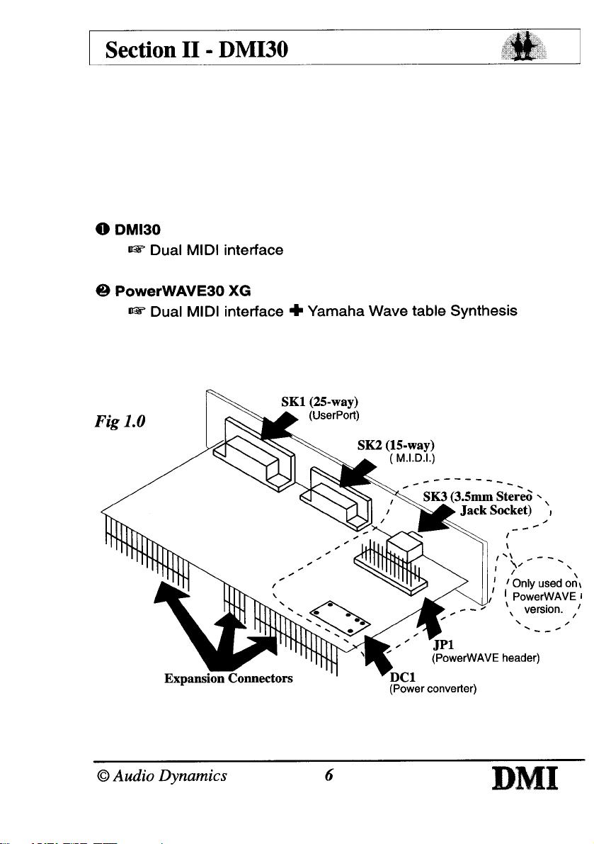
The DMI30 is a dual MIDI interface designed for the A30x0 & A4000
Acorn RISC OS machines.
It is a standard Acorn "mini-expansion" card and fits internally.
Variations
There are currently two variations :
Fig 1.0 shows the DMI card and all of its sockets/connections.
If you have purchased the PowerWAVE30 XG then you should also
Page 7
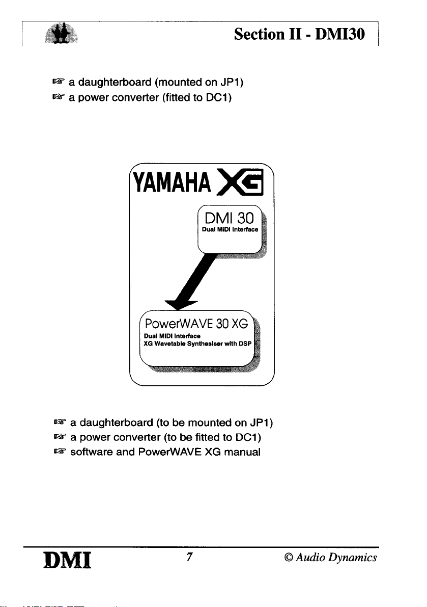
have:
Upgrades
If you own the basic DMI then you can upgrade to the full
PowerWAVE XG.
The upgrade requires no tools or specialist knowledge to fit and
consists of :
Page 8
Connections
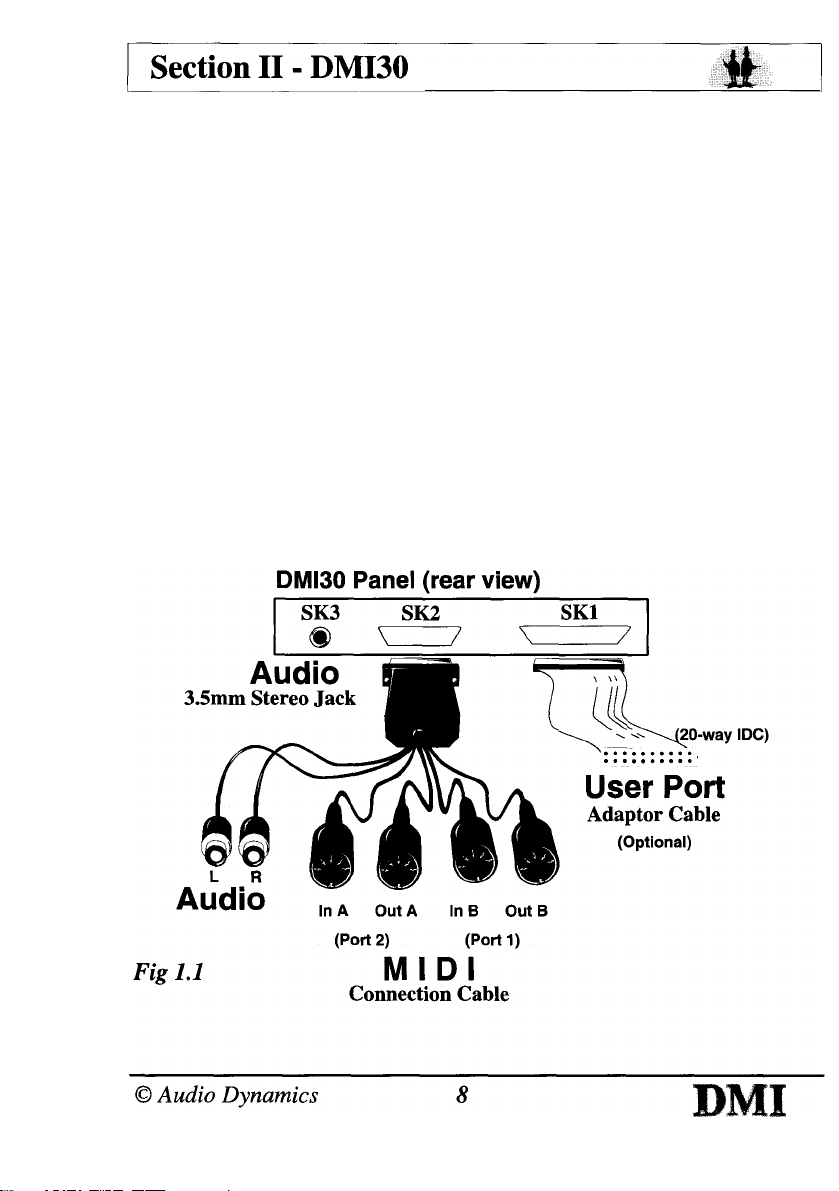
MIDI (SK2) : to connect your DMI /PowerWAVE interface to external
MIDI equipment all you need to do is plug your MIDI connection
cable into SK2, and then your external MIDI equipment into the
In/Out(s) on your MIDI connection cable.
Audio (SK3) : if you have purchased a PowerWAVE/XG card then
SK3 and the audio phonos (supplied as part of the MIDI connection
cable) become active as Audio Output for connection to an
amplifier or headphones.
User Port (SK1) : the (optional) adapter cable converts the 25-way
D-connector (SK1 ) to a 20-way IDC socket. The IDC socket can
then be connected to a concept keyboard for example.
(NB. The standard User Port 20-way iDC socket can no longer be fitted to expansion
cards because it does not comply to new EMC regulations)
Page 9
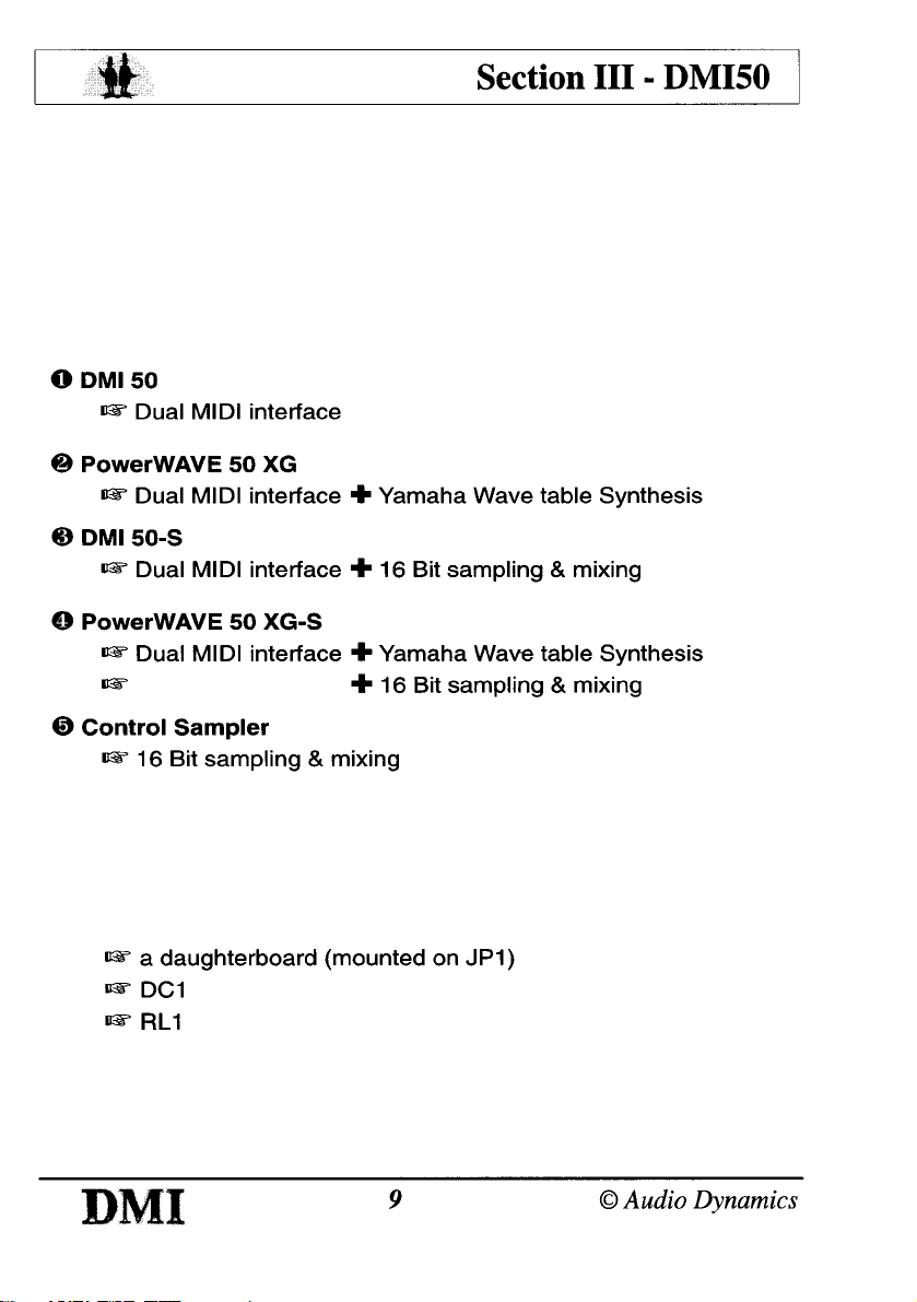
The DMI 50
The DMI 50 is a dual MIDI interface designed for the Acorn A5000 &
Risc PC RISC OS machines. It is a standard Acorn expansion card
and fits internally. In addition to MIDI the DMI 50 also offers 16 Bit
CD-Quality sampling capabilities.
Variations
There are currently five variations :
Fig 2.0 (over page) shows the DMI card and all relevant sockets/
connections.
If you have purchased the PowerWAVE 50 XG (2 or 4 above) then
you should also have :
Page 10
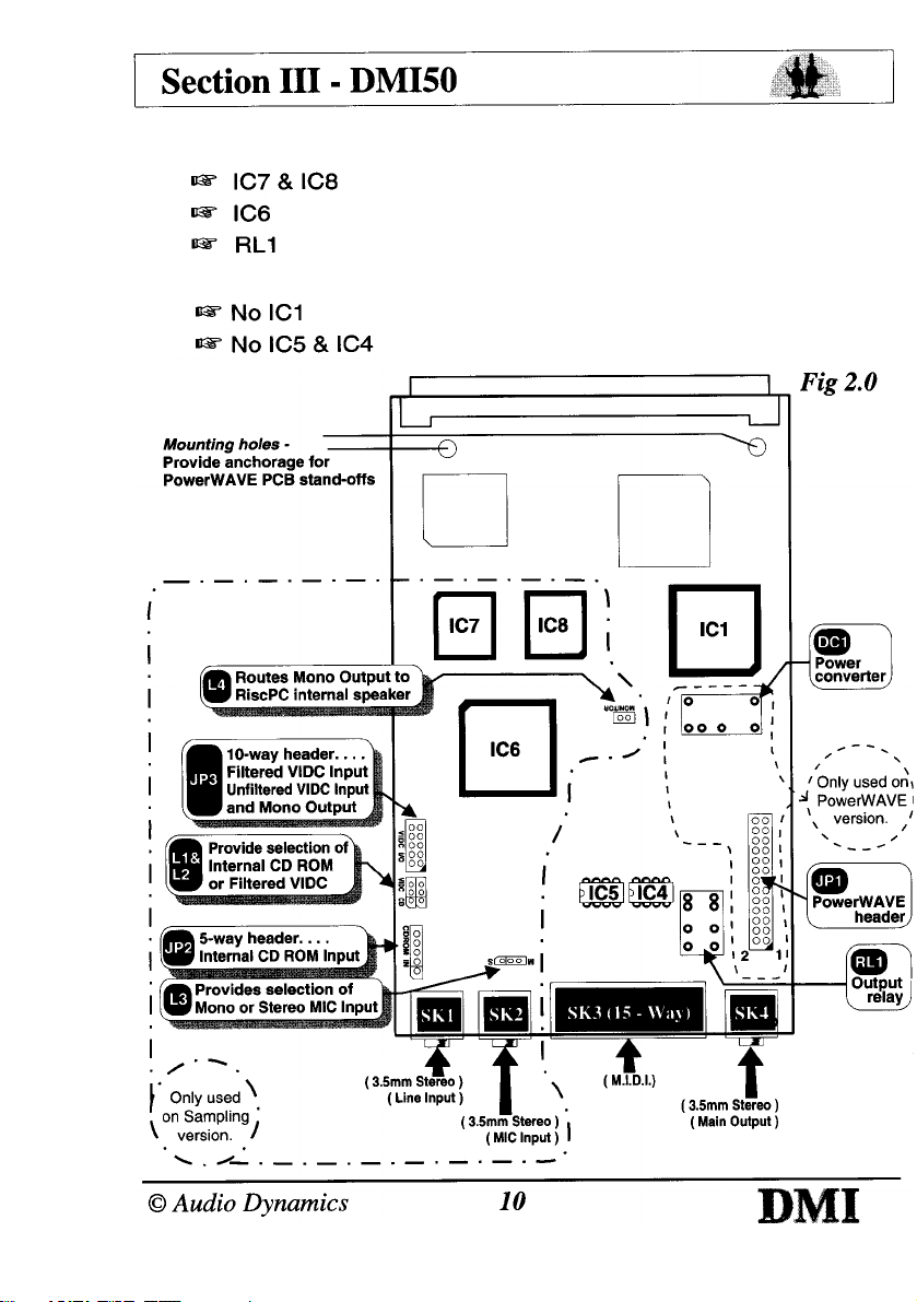
If you have purchased one of the sampling variations (3, 4 or 5 on
previous page) then you should also have :
The non-MIDI "Control" sampling variation (5) has :
Page 11
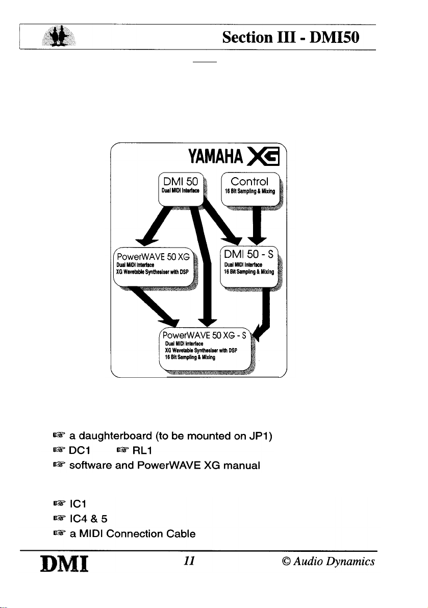
The PowerWAVE 50 XG-S is the only version to have a fully
populated main PCB.
Upgrades
All variations of the DMI 50 can be upgraded to the full
PowerWAVE 50 XG-S.
Synthesis : If you own the basic DMI then you can upgrade to the
full PowerWAVE XG.
The upgrade requires no tools or specialist knowledge to fit,
It consists of :
If you own the non-MIDI Control sampling card then you also need :
Page 12
If you own an early Ensoniq PowerWAVE synthesiser you can upgrade to the full
Yamaha PowerWAVE XG card.
Sampling : If you own the basic DMI then you can upgrade to the
DMI 50-S. this consists of :
If you own the PowerWAVE XG then you can upgrade to the
PowerWAVE XG-S. The upgrade is the same as the DMI 50-S
without RL1 which is already fitted.
Contact your dealer for more information about the various upgrades
available.
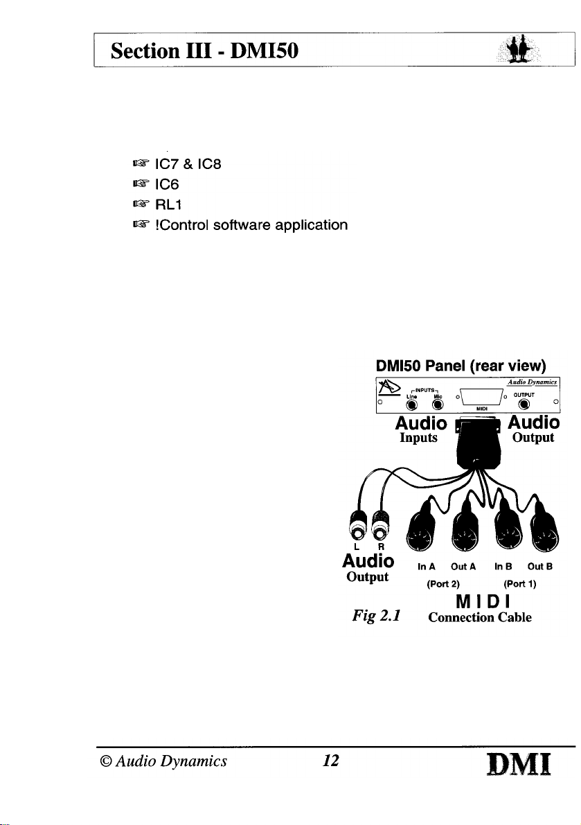
Connections
MIDI (SK3) : to connect your
DMI /PowerWAVE interface to
external MIDI equipment all you
need to do is plug your MIDI
connection cable into SK3, and
then your external MIDI
equipment into the In/Out(s) on
your MIDI connection cable.
Audio Output (SK4) : if you
have purchased a
PowerWAVE XG or sampling
card then SK4 and the audio
phonos (supplied as part of the
MIDI connection cable)
become active as Audio
Output for connection to an amplifier or headphones.
Audio Inputs (SK1 & SK2) : if you have purchased a sampling card
then SK1 & SK2 become active as Audio Inputs for connection to
external Line-level and Microphone inputs.
Page 13
Connecting your MIDI system
Connection to and from each MIDI device is made using MIDI leads MIDI
leads can vary in length, the maximum lead length as defined by the MIDI
Manufacturers Association is 15 metres (about 50 feet) but problems can
be encountered when introducing cables of this length.
The golden rule is, try to keep the leads as short as is
practical and avoid running them close to other
electrical equipment.
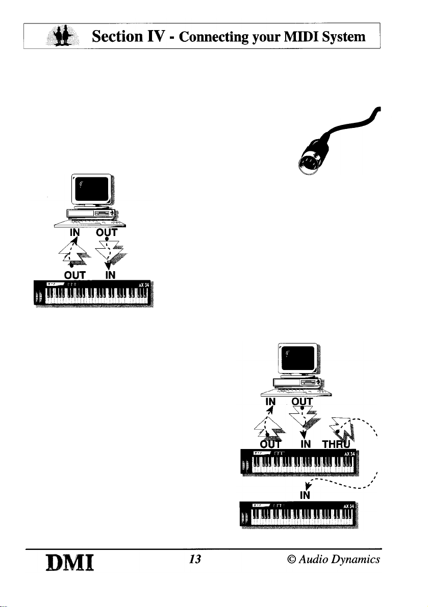
A MIDI interface can vary in the number of
connections it provides, though most
interfaces have IN, OUT & THRU. The
simplest connection therefore is one from
your computer straight to one other MIDI
device.
The "Out" from the computer is connected
to the "In" of the external instrument and
vice-versa.
To connect more than one instrument the "Thru" of the first
instrument can be linked to the "In" of the second one.
This has the effect of passing-on the
MIDI information from the computer so
that it can be seen by all the instruments
in the chain.
Using this method of connection only
one MIDI port is used even though there
are two instruments connected to it.
From this it might appear that it would
be possible to construct an indefinitely
long chain of instruments simply by
linking the "Thru" of each one to the
following "In".
In reality however this is not the case
as a small delay is put into the chain by
Page 14
each instrument, and by the fourth or fifth instrument in the chain this
delay may become audible.
The amount of delay introduced will depend on how each individual
instrument performs its Thru function. If the Thru is purely an
electronic one, passing the MIDI "In" data straight on, then the delay
will be very small. However some instruments use software to derive a
"Thru" function and this usually takes much longer.
Experimentation with the instruments at your disposal is the best
way to discover your systems limits.
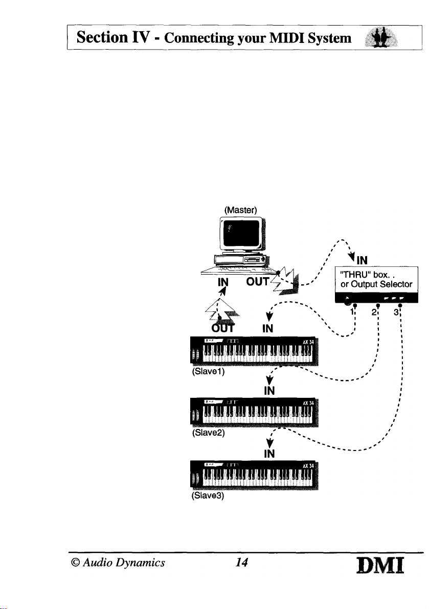
One solution to this problem is to use a MIDI Thru box.
MIDI Thru boxes passon information from the
Master (the first
instrument supplying
the MIDI data) to all
the Slaves (the
instruments receiving
the MIDI data) at the
same time.
This has the effect of
placing only one small
delay in the chain for
all the instruments that
are connected.
It is worth
remembering though,
that the DMI has two
independent MIDI
ports, giving you twice
the capabilities of a
single MIDI interface!
Page 15
RISC OS MIDI
As the DMI is a dual MIDI interface it is capable of transmitting and
receiving across two completely independent ports. Each port
contains sixteen MIDI channels giving a total of thirty two.
This significantly increases the number of instruments which can be
incorporated into arrangements, and allows greater flexibility in the
range of options available.
For instance, the internal PowerWAVE XG synthesiser card is
capable of responding to all sixteen MIDI channels on a single port.
The DMI goes on to provide a second port, which can then be
connected to further external music equipment ie. keyboards,
modules etc.
Most RISC OS music software applications cater for this, however
some of the earlier programs assume a single MIDI port.
On the DMI, the PowerWAVE synthesiser card always occupies the
lower port (Port 1), meaning it will respond to single MIDI port
applications.
Page 16
An introduction to MIDI
MIDI is an abbreviation of Musical Instrument Digital Interface.
It is a standard which allows several electronic instruments, such as
synthesisers and drum machines to be connected together so that
they can interact and be controlled from a common source, providing
they all have a MIDI interface.
The MIDI interface usually consists of a transmitter and receiver (
OUTput and INput respectively) and sometimes a thru, although
some keyboards or modules will only have either an output or an
input depending on their intended purpose.
For example a controller keyboard cannot produce any sounds of its
own so it has no MIDI in. Conversely a sound module has no
keyboard from which to send control information, so has no MIDI out,
although it could be fitted with a thru to allow it to "pass-on" the MIDI
information being sent to its IN.
MIDI signals consist of standard codes which contain information
about which keys have been pressed, released, which MIDI channel(
s) are being used, which instrument or sound to play, and a whole
host of controllers which can be used if the receiver has the ability to
understand them.
Because of the digital nature of MIDI, and the fact that all MIDI
communication must comply to a standard, the information can be
stored and edited by a computer fitted with a MIDI interface. Using
the power of the computer, the user can play and control several
different musical parts on several instruments at the same time.
The facilities the computer provides will depend on the application
software used. There are a variety of programs available ranging from
simple "one note at a time" playback using pictures to represent
tunes, to full real-time capture applications which allow you to "record"
several sections of music in turn from a MIDI keyboard, and then
reproduce all the parts together, not only audibly but also in the form
of a high-quality printed music score.
Your Acorn Dealer should be able to show you a range of music
software and help you decide which application best suits your
Page 17
individual needs.
There are also regular articles, reviews and advertisements in the
Acorn press for music related software.
MIDI Instruments
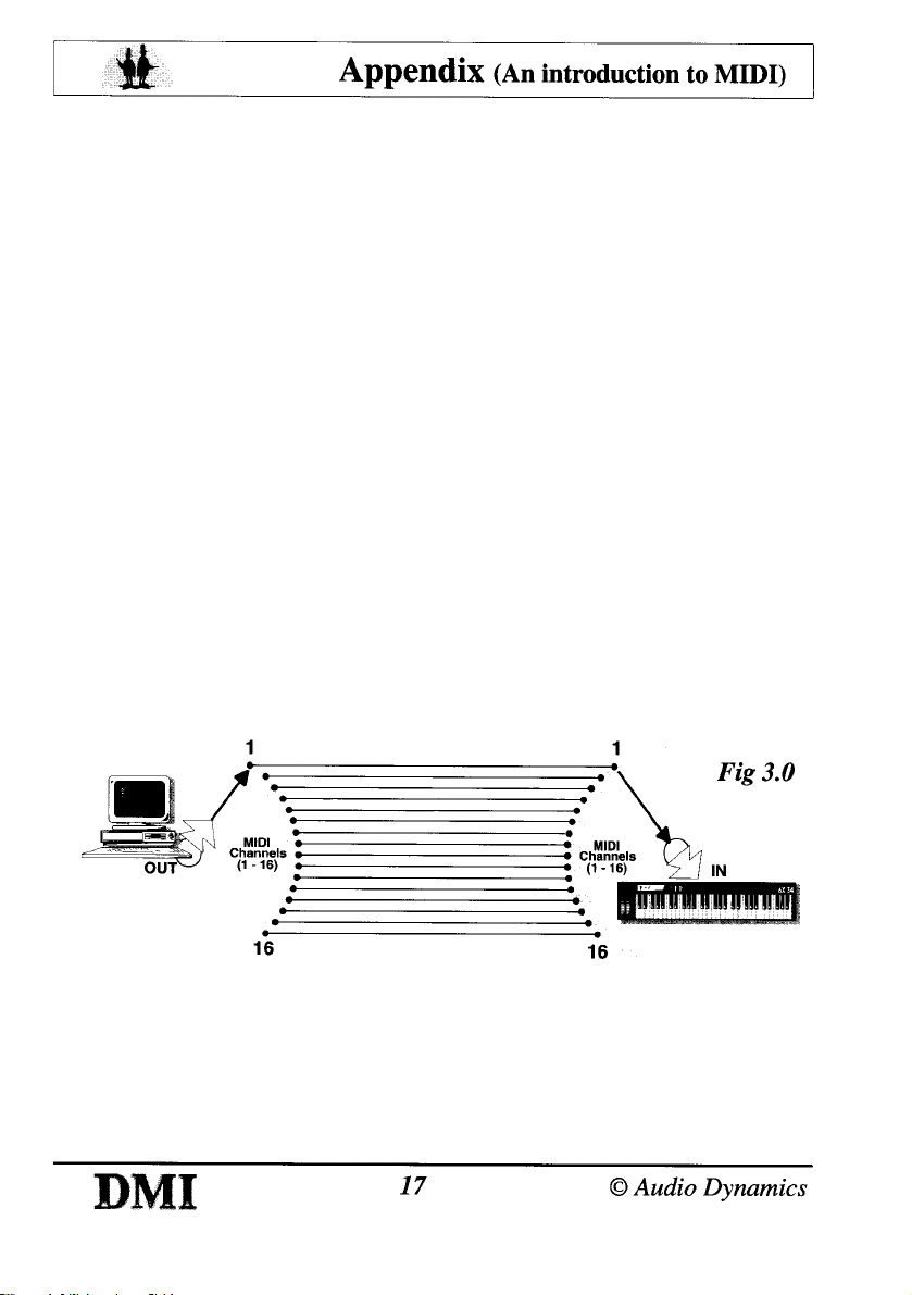
Each MIDI port actually contains 16 separate MIDI channels. Each
channel can control any one of the sounds provided by the
Synthesiser to which it is connected, and could play (potentially!) up to
128 notes at any one time, although this would probably not sound
very pleasant!
In reality this would be restricted by the number of notes playable
simultaneously by the synthesiser (the polyphony), as synthesisers
vary enormously in their specifications depending on their price and
age.
Lower cost or older MIDI synthesisers will be able to play fewer notes
simultaneously (typically 8) and may only be able to use one MIDI
channel at a time (fig 3.0). It is therefore important to check, if this is
the case, that the synthesiser is set to the same MIDI channel
number as the one you are using on the computer or other MIDI
device, otherwise no communication will take place.
Always read the MIDI section of your synthesiser's manual fully
before attempting any MIDI connections.
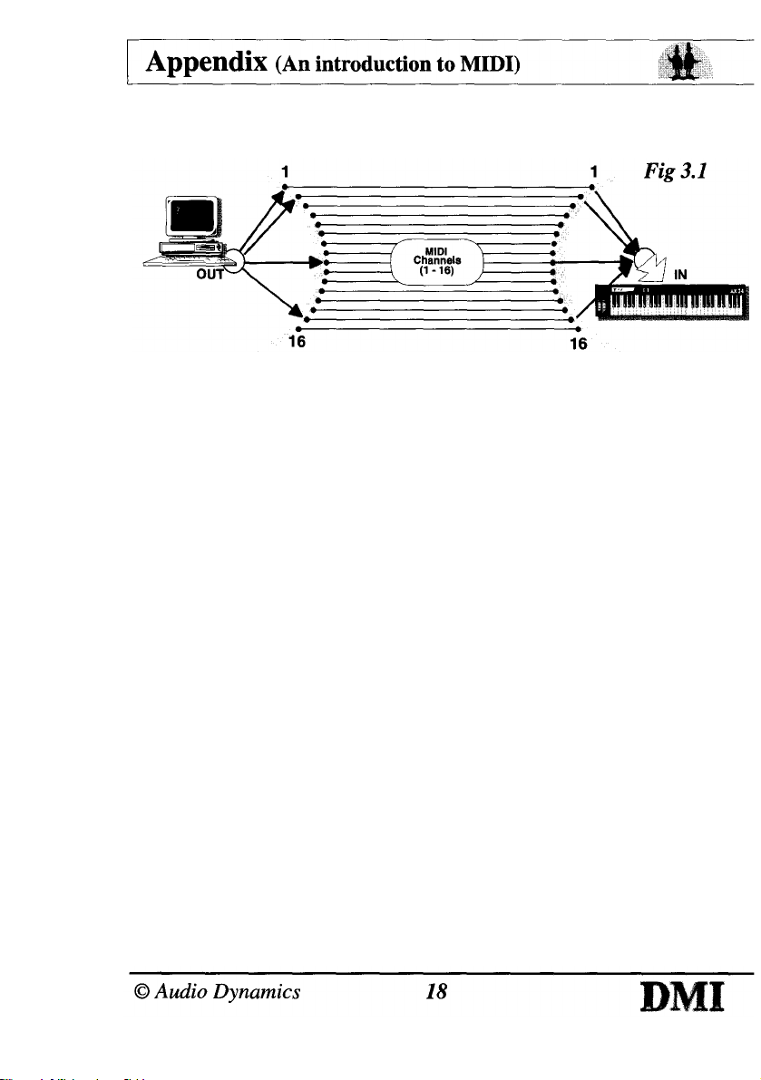
Synthesisers which can receive information on more than one MIDI
channel at a time and play the required instruments simultaneously
are known as multi-timbral (fig 3.1).
This is one of the requirements if a particular synthesiser is to
comply with the standard known as General MIDI.
Page 18
General MIDI
General MIDI was created in order to provide a standard to which
synthesiser manufacturers and users could comply in order to
maintain compatibility with each other.
The General MIDI specification outlines a minimum MIDI
configuration of a "General MIDI System".
The General MIDI (or GM) system provides a high degree of
compatibility between MIDI synthesisers, and adds the ability to play
songs (in the form of MIDI data) created for any given synthesiser
that follows this specification.
For example the GM specification states that patch number 1 will
always be an acoustic grand piano, and continues through the list
specifying all 128 patches. This means that a composition created
on one GM instrument will still select the correct sounds when
played on another. The quality of each sound however, will depend
on the individual instrument.
It describes a minimum number of voices, sound locations, drum
note mapping, octave registration, pitch bend range, and controller
usage, thereby defining a given set of capabilities to expect in a
given synthesiser.
The GM level 1 performance requirements are listed in the appendix.
Page 19
GM Sound Generator
Synthesis / Playback Technology (Sound Source Type)
le. Subtractive, Additive, FM, Wave table. - Up to the Manufacturer.
Number of Voices
A minimum of :
24 fully dynamically allocated voices available simultaneously for
both melodic and percussive sounds.
Or:
16 dynamically allocated voices for melody plus 8 for percussion.
MIDI Channels Supported
All 16 MIDI channels
Each channel can play a variable number of voices (polyphony)
Each channel can play a different instrument (timbre) Key based
percussion is always on channel 10
Instruments
A minimum of 128 presets for instruments (MIDI program numbers),
conforming to the GM sound set.
A minimum of 47 preset percussion sounds conforming to the GM
percussion map.
NB. The PowerWAVE synthesiser is a 16-bit wave table type
It has 32 note polyphony (voices) and can receive information
on all 16 MIDI channels simultaneously.
It has 128 instruments and 47 percussion sounds all
conforming to the GM map.
It plugs directly on to the DMI without the need for any external
MIDI leads and reads the MIDI information from one of the ports
without interrupting that port's output.
Page 20
GM Protocol Implementation
Note on / Note off
Octave registration : Middle C = MIDI key 60 (3CH)
All voices, including percussion, respond to velocity
Voices dynamically allocated (notes / drums can re-attack using free
voices)
Controller changes
Controller No. Description
1 Modulation
7 Volume
10 Pan
11 Expression
64 Sustain
121 Reset all controllers
123 All notes off
Registered parameter No.
0 Pitch bend sensitivity
1 Fine tuning
2 Coarse tuning
Channel messages
Channel pressure (Aftertouch)
Pitch bend (Default range = 2 semitones)
Default settings
Bend = "0", Volume = "100" (0 - 127), Controllers "normal"
Note : GM specifies that channel 10 is reserved for percussion.
When accessing channel 10 the individual percussion sounds are
played using different keys on the MIDI instrument and not by
selecting patch numbers.
Page 21
Problem Possible Solution
Nothing happens when I
play from the computer.
(No MIDI Output)
Nothing happens when I
play from the keyboard.
(No MIDI Input)
Ensure all cables are firmly connected.
Remember, the OUT connectors are
mapped :
DMI's OUT A = Port2
DMI's OUT B = Port1
And so, your software will probably
default to Port1 which is in fact OUT B,
so connect your keyboard's IN to OUT
B.
Your software may have a MIDI option
which should be selected.
Ensure all cables are firmly connected.
Remember, the IN connectors are mapped
DMI's IN A = Port2
DMI's IN B = Port1
And so, your software will probably
default to Port1 which is in fact IN B, so
connect your keyboard's OUT to IN B.
Ensure your software is in a record mode.
Page 22
Notes
Page 23
Page 24

©1996
Audio Dynamics
Why cause ripples . . . . when you can make waves !!!
 Loading...