

Page 1

CONTENTS
SCENARIO 1
INTRODUCTION 3
UNPACKING 3
VISUAL INSPECTION 3
SPECIFIC POINTS 3
IMPORTANT SAFETY INSTRUCTIONS 5
POWERING 6
TECHNICAL SPECIFICATION 8
EQUALISATION CURVES 11
BLOCK DIAGRAM 12
CONNECTOR PANEL 13
CONNECTIONS 14
INPUT MODULE 16
OUTPUT MODULE 18
ADJUSTMENTS AND CALIBRATIONS
21
AD100-09 POWER SUPPLY UNIT 24
CUSTOMER NOTES AND FACTORY MODIFICATIONS 25
TECHNICAL LIBRARY 26
SCENARIO
Page 2

1
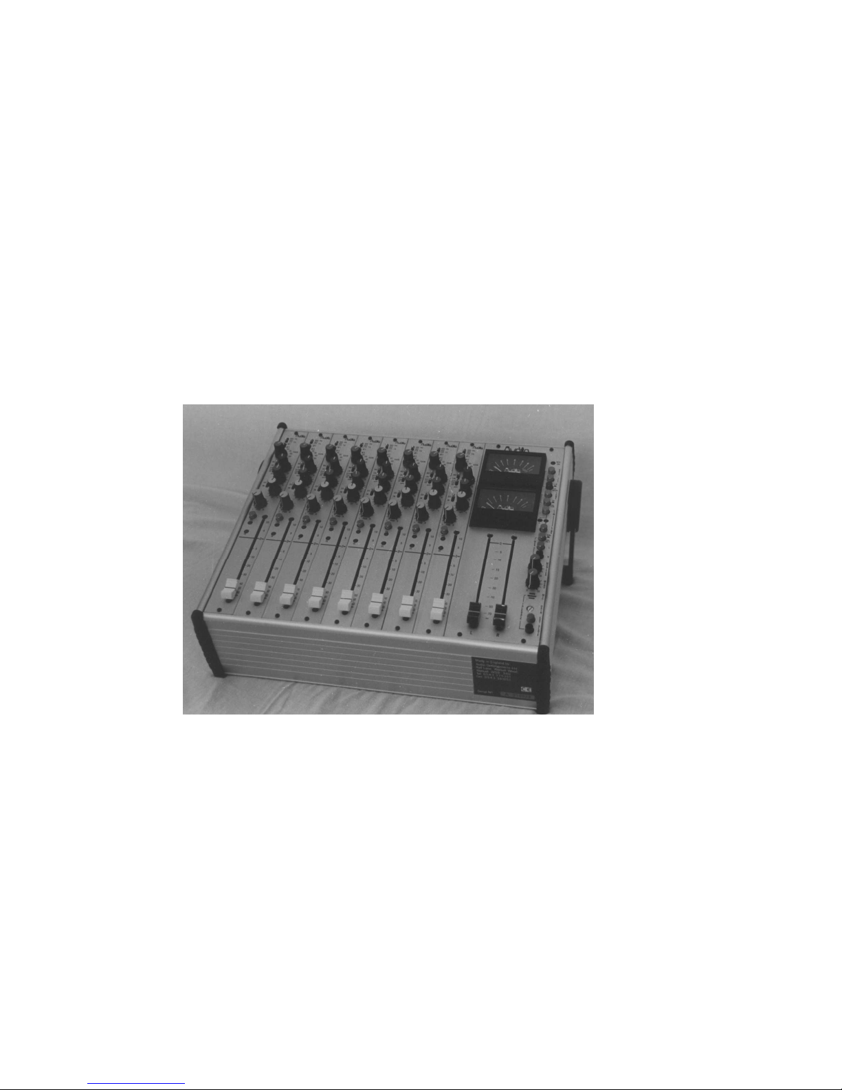
Time was when it became necessary to update the ubiquitous AD145 PICO mixer.
Our survey showed two main requirements: as well as Audio Developments' build
and audio qualities, narrower and shorter modules were required, and the simple but
effective equaliser from PICO had to be retained. By this time, 4-track recording
equipment had begun to trickle into the marketplace (Nagra D etc), so we decided to
give the new mixer four outputs. Because of the lower noise-floor of modern digital
recorders, the level of input signals may be reduced. We have taken advantage of
this fact and lowered the slope ratio of the limiters to 7:1. By so doing, not only is
signal distortion greatly reduced, but also the artefacts associated with limiters
become much less noticeable or objectionable. Also, sixty years after the event,
sound engineers have come to realise the potential of Blumlein's M-S techniques; to
this end, facilities have been incorporated to take advantage of these
techniques. The result is AD146 - a four-output mixer.
This was followed by AD148 - edit mixer. Based on AD146, two comprehensive left
and right monitor modules have been added for editing purposes. If a mic/line
module is included for commentary or voice-over purposes, its input-gain switch can
be changed to a potentiometer, and its gain structure changed to ensure consistent
level matching with a fixed, mechanical point of reference. Unfortunately, this way of
working does reduce headroom and also compromises a mixer's noise performance.
After AD146/AD148 it was back to the drawing board. Our customers were still
demanding a two-output mixer - as a true replacement for the PICO, and with the
PICO's simplicity. Despite past assurances to the contrary, T powering is still
required. And could we incorporate auxiliaries? And could we possibly bring it to
market at 'entry level'? We have, and we have and that's MERCURY (AD147).
AD149 completes the 140 series of mixers, and has a repertoire of party tricks not to
be found in any other mixer - not even for 'ready money'. The design team took, as
its starting point, our list of all the ideas and suggestions presented to us over the past
few years. Many of these requests came from film-sound recordists - a sub-set of
recordists we have unintentionally neglected in the past.
Since the days of R & D for AD146, channel insert points suddenly became de
rigueur. It transpires that many sound engineers have experienced the power of
FLEX-EQ, our industrial-strength equaliser, and wish to be able to use it when making
original recordings.
Page 3
2
Being latter-day converts, we have included circuitry to take full advantage of all M-S
techniques - even shuffling - in both production and post-production.
AD149 is Audio Developments' tribute to, and celebration of the genius of Alan
Blumlein.
We appeal to all AD149 users to break with tradition and, just on this occasion, study
the manual to reveal all the mixer's secrets.
THIS IS ESSENTIAL.
Well - we HAD every intention that AD149 would complete the 140 series.
We'd reckoned, however, without the persistence - nay, insistence - of our customers
for a mains-operated version of the AD146 with four auxiliaries ...
we've called it AD144.
Radical change and PICO have proved to be uneasy bedfellows: never a matinée
idol and denied its dulce et decorum death, AD145 has now been repackaged in the
140 series metalwork - thereby reducing its size and weight. Facilities remain
largely unchanged: internally, the microphone amplifier has been replaced with
the one designed for AD146 and externally, the mono return is now in stereo form.
Now designated AD245, shall we have PICO - like the poor - always with us?
Page 4

3
INTRODUCTION
Unpacking
If there are any signs of damage to the outside of the carton, please notify us or your
supplier immediately, regardless of the unit's apparent physical condition. This is in
case a claim has to be made at a later date because of previously undetected transit
damage. The packaging material should not be discarded until the mixer has been
acceptance tested and a suitable transit/storage case is available for secure, safe
storage.
Visual Inspection
Identification - please make a separate note of the serial number for your own capital
equipment records. Ensure that it agrees with the number on the invoice/packing
note. The serial number label is on the back cover, adjacent to the battery
compartment.
Temperature - check the meter glasses for condensation. If the package has been in
transit during cold weather, leave the mixer for at least 12 hours to allow it to return to
normal room temperature. Any measurements or subjective tests then made, will be
to a known temperature reference.
Specific Points
Battery compartment - the mixer has an integral battery compartment to accept
8
size-C cells, and is formed as part of the bottom transversal extrusion. This helps to
lower the centre of gravity, as well as adding to the rigidity of the frame.
DC-DC converter - is mounted on the top side of the battery housing and is
underneath the fader section of the modules.
In order to facilitate the testing and calibration of all modules, a set of two extender
modules is available from the factory.
Connectors - for convenience, the connector panel is labelled for reading from above.
All connectors are in line with their corresponding module.
Page 5
4
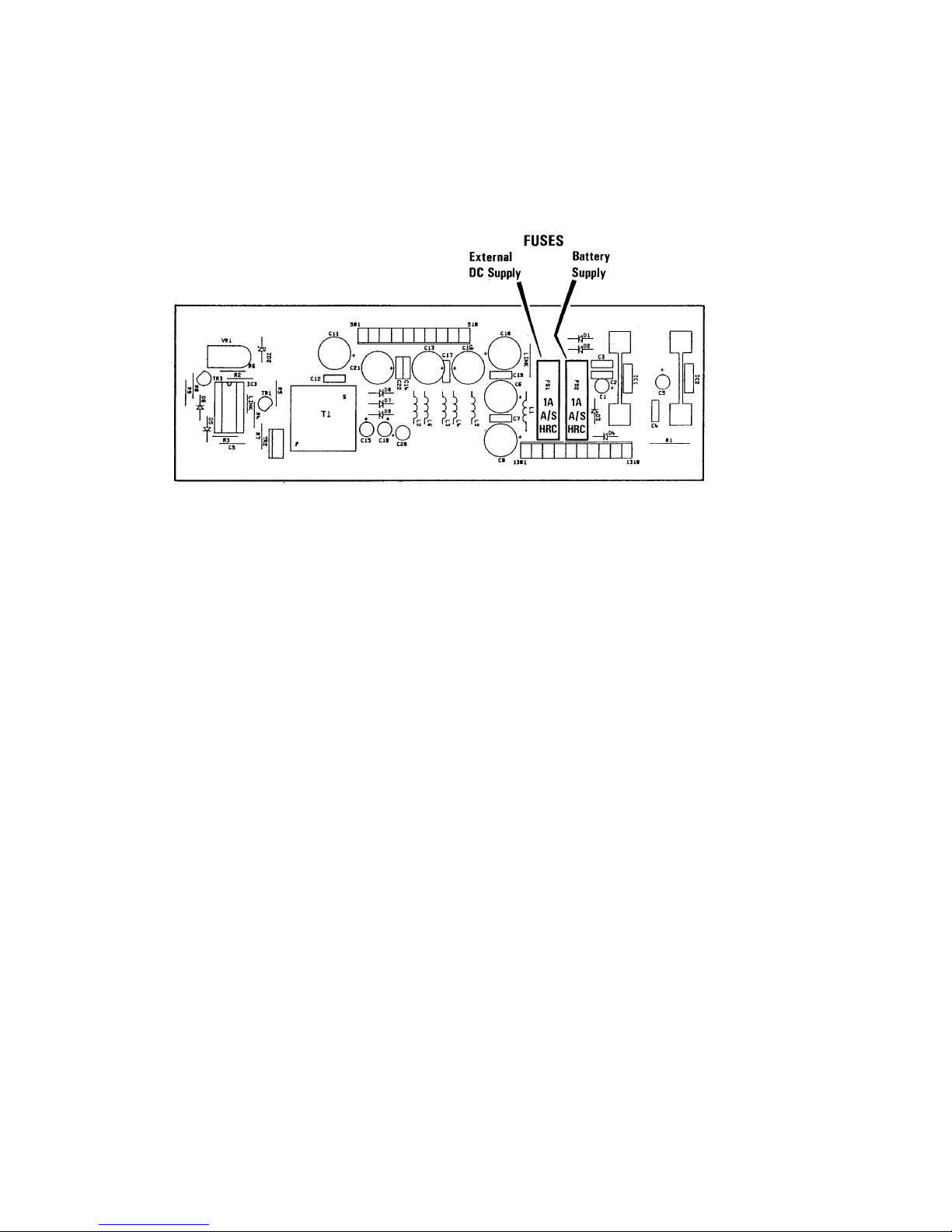
Fuses - to protect the mixer and internal power supply are mounted on the power
supply/converter board. Access is gained by removing the output module. 20mm, 1A
ANTI-SURGE HRC fuses are used - one for the internal battery power supply and one
for the external DC supply.
Limiter threshold - is set at the factory at +8dBu (PPM 6), but an internal preset
potentiometer allows adjustment to any other level above 0dBu. The limiters are to
be found on the output module printed circuit board.
Microphone powering - the mixer will remain unconditionally stable if the powering on
unterminated input channels is switched off - this also improves the noise
performance and crosstalk. Powering - 48v phantom or 12v tonader - may be
selected before or after the microphone is connected to the module.
Module fix screws - Hexagon head screws are used to fix the modules and back
cover. The size being 1.5mm HEX A/F with a 2.5M thread.
If it becomes necessary to remove modules or back cover it is strongly advised using
a good quality hexagonal head driver.
Use of a screwdriver, however desperate, is not recommended.
Finally, may we draw your attention to our range of portable, battery-operated audiotoys called PORT-A-FLEX (AD066) which will complement your new mixer.
No 1 - broadcast quality compressor/limiter. Nos 3,7,8,10 - distribution amplifiers for
microphone and line-level signals. No 13 - the aforementioned FLEX-EQ in its
portable guise.
We wish you many trouble-free hours of use from your mixer. As a company, we are
fully committed to BS EN ISO 9001. Should you have any problems or require any
further information on FLEX-EQ or the M-S microphone technique, please do not
hesitate to contact us on 01543 375351 or by fax on 01543 361051.
Page 6

5
WARNING
IMPORTANT SAFETY INSTRUCTIONS
The user of electrical products must be familiar with their potential dangers, and
fundamental precautions must always be taken. Please read the following text
carefully.
Power supply units manufactured by Audio Developments Ltd are not user
serviceable. There are no user-serviceable parts associated with any such power
supply unit.
THE OUTER COVERS MUST NOT BE REMOVED
Such a power supply unit is solely for use with audio mixers and sound processors hereafter called the equipment - manufactured by Audio Developments Ltd.
Always use a cord set accepted by a National Approved Body.
EARTHING/GROUNDING: When using an external power supply unit that is
connected to the mains supply to drive the mixer it must be CONNECTED TO
EARTH.
In certain types of malfunction or breakdown, earthing provides a path of least
resistance for electric current and considerably reduces the risk of electric shock.
DANGER: Incorrect connection of the equipment grounding/earthing conductor can
result in the risk of electric shock. Where possible obtain a pre-wired mains lead from
a reputable supplier with the correctly fitted mains connector for the type of mains
outlet in use; otherwise, one correctly wired and checked by a qualified electrical
engineer. If your mains lead is not suitable for the mains outlet, have the correct plug
fitted by qualified personnel.
The MAINS PLUG of this equipment is the primary disconnect device. Therefore, in
the final application, ensure it remains close to the equipment and easily accessible.
Page 7

6
POWERING
The mixer may be powered from either internal cells or an external DC power source.
The integral battery compartment requires a total of 8 size-C cells. Access is gained
via a captive lid which is retained by two, 90-degree-turn buckles. The lid hinges
outwards 45 degrees from the back panel. When installing new cells, the row
nearest the hinge should be fitted first.
Either conventional dry, or rechargeable nickel-cadmium cells may be used. NICADs
may be recharged in situ through the 4-pin POWER IN connector. (The circuit for
recharging is already incorporated within the mixer.) A voltage in the range +15v to
+24v DC @ 250mA is required on PIN 2 of the POWER IN XLR.
When driving the mixer from an external power source, PIN 1 is the 0v connection
and a voltage in the range +12v to +15v DC should be supplied to PIN 4. The power
source should be capable of delivering approximately 400mA - allowing some
capacity for phantom powering.
If an external power supply unit (PSU) is to drive the mixer and simultaneously charge
a set of NICADs, a current capability of at least 650mA is required. It is poor practice
to run a PSU at its limit, therefore we recommend a minimum of 750mA.
Audio Developments AD100-09 PSU is a suitable unit.
WARNING: When NOT using the PSU (AD100-09) supplied for the mixer, ensure
your 4-pin XLR is correctly wired to match the POWER IN connector. Failure to do
so may result in the breakdown of the internal DC-DC converter. Make this check
even if using a PSU which may have been supplied to you in the past, eg AD100-06.
AD100-05 PSU is NOT suitable for use with an AD245 mixer and must not be used.
Page 8

7
THIS PAGE IS BLANK
Page 9

8
TECHNICAL SPECIFICATION - ELECTRICAL
REFERENCE 0dB=775mV at 1kHz unless otherwise stated.
MAX GAIN MIC 80dB
LINE 50dB
MAX INPUT LEVEL MIC @ MAX GAIN -44dB @ MIN GAIN + 6dB
LINE @ MAX GAIN -14dB @ MIN GAIN +20dB
STEREO-RETURN +18dB
TB RETURN +18dB
INPUT IMPEDANCE MIC >2k5R
LINE >6k5R
STEREO-RETURN >100kR
TB RETURN >20kR
MIC POWERING 48v PHANTOM & 12v TONADER
MAX OUTPUT +23dBm L-R TRANSFORMER BAL
(600R LOAD) MONO TRANSFORMER BAL
+18dBm H’PHONE MONITOR UNBAL
(600R LOAD) TB SEND UNBAL
OUTPUT IMPEDANCE <60R L-R & MONO
<20R MONITOR
<20R TB SEND
FREQUENCY RESPONSE 0: -1dB L-R & MONO
0: -1.5dB MONITOR PATHS
HARMONIC DISTORTION <0.05% @ 1kHz @ 0dBm OUTPUT
<0.15% @ 40Hz to 15kHz @ +15dBm OUTPUT
OVERLOAD INDICATOR ILLUMINATES @ +15dBu at the PRE-FADER POINT
CROSSTALK <-70dB 40Hz to 15kHz
INTERGROUP & INTERCHANNEL
NOISE MIC <-126dB EIN 20Hz to 20kHz; 200R SOURCE
LINE <77dB SNR 20Hz to 20kHz 0dBu IN & OUT
EQUALISATION HF: 10dB @ 10kHz
Page 10

9
LF: 10dB @ 100Hz
MF: 15dB
CENTRE FREQUENCY 2k5Hz Q=1.2
HPF: PRE-TRANSFORMER 12dB/OCTAVE
-3dB @ 150Hz
-3dB @ 90Hz
OUTPUT LIMITER THRESHOLD +8dB
RATIO 7:1
ATTACK 2 SETTINGS INTERNALLY SWITCHABLE
1: 4mS 2: 0.8mS
RELEASE 2 SETTINGS INTERNALLY SWITCHABLE
1: 250mS 2: 80mS
FACTORY SETTING: SLOW
CURRENT CONSUMPTION 180mA (6 INPUT)
12v DC SUPPLY
Page 11

10
TECHNICAL SPECIFICATION - MECHANICAL
SIZE
6 I/P 8 I/P 10 I/P 12 I/P
A 320 381 442 503
B 295 356 417 478
ALL DIMENSIONS IN MILLIMETRES
WEIGHT
6 I/P 8 I/P 10 I/P 12 I/P
6 7 8 9
ALL WEIGHTS IN KILOGRAMS
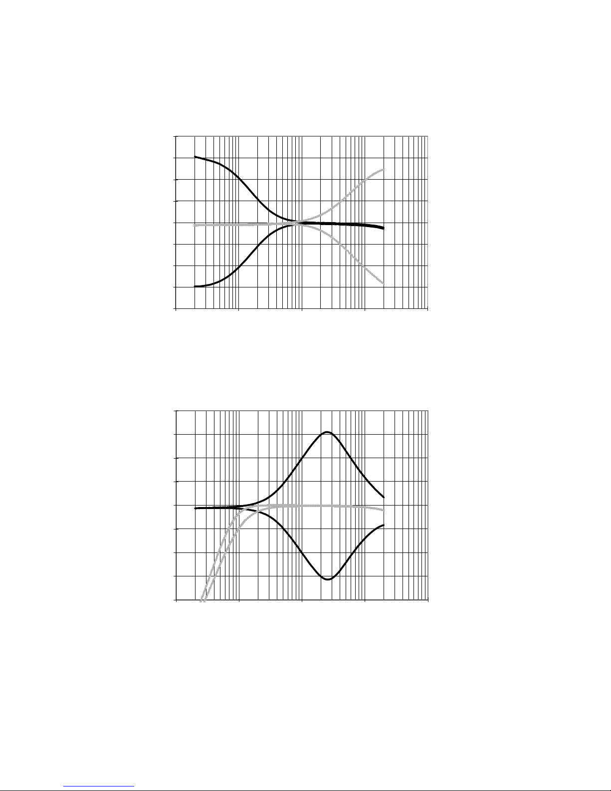
EQUALISATION CURVES
Page 12
11
AD 245 HIGH AND LOW EQ
-20
-15
-10
-5
0
5
10
15
20
10 100 1000 10000 100000
FREQUENCY
dB
AD 245 MID EQ AND HPF
-20
-15
-10
-5
0
5
10
15
20
10 100 1000 10000 100000
FREQUENCY
dB
Page 13
12
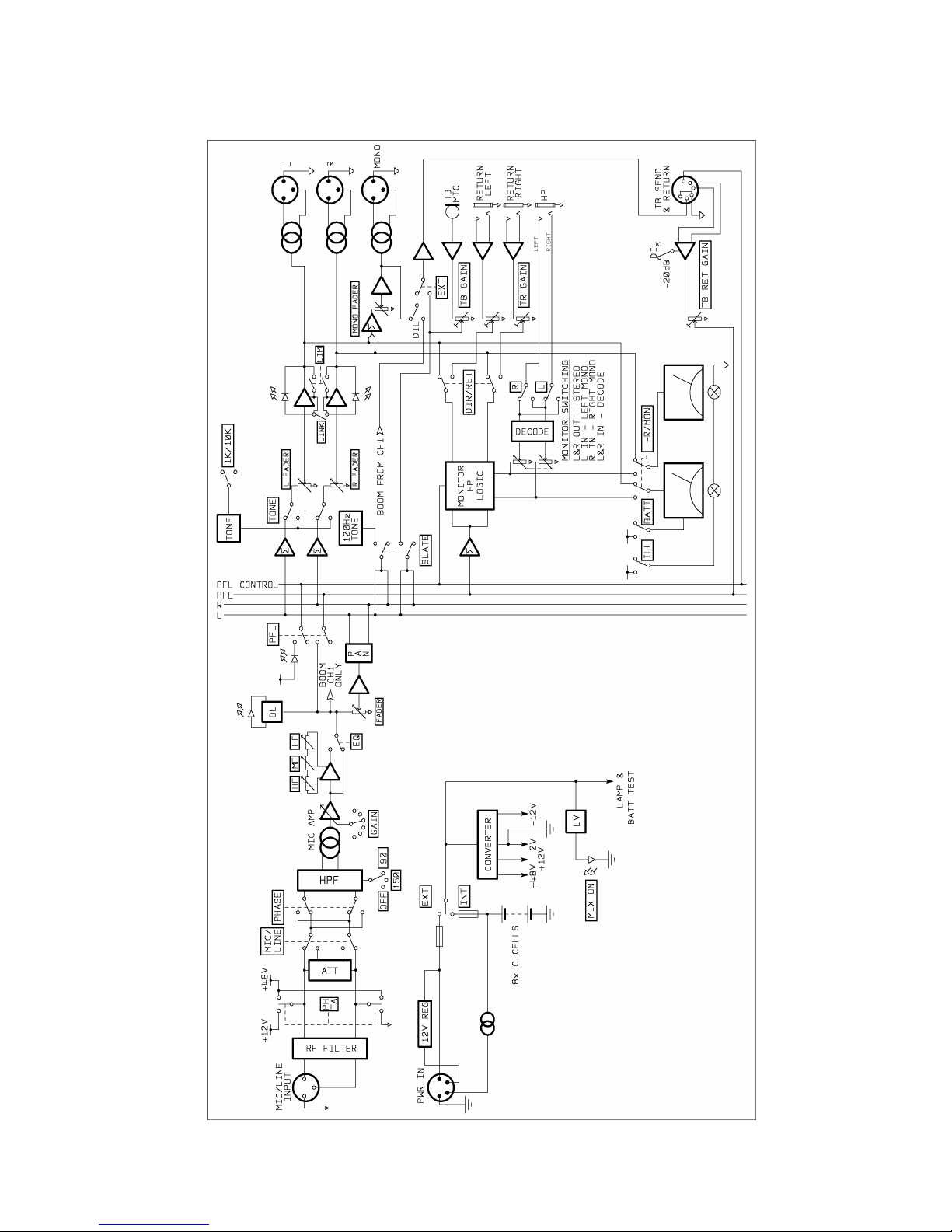
BLOCK DIAGRAM
Page 14
13
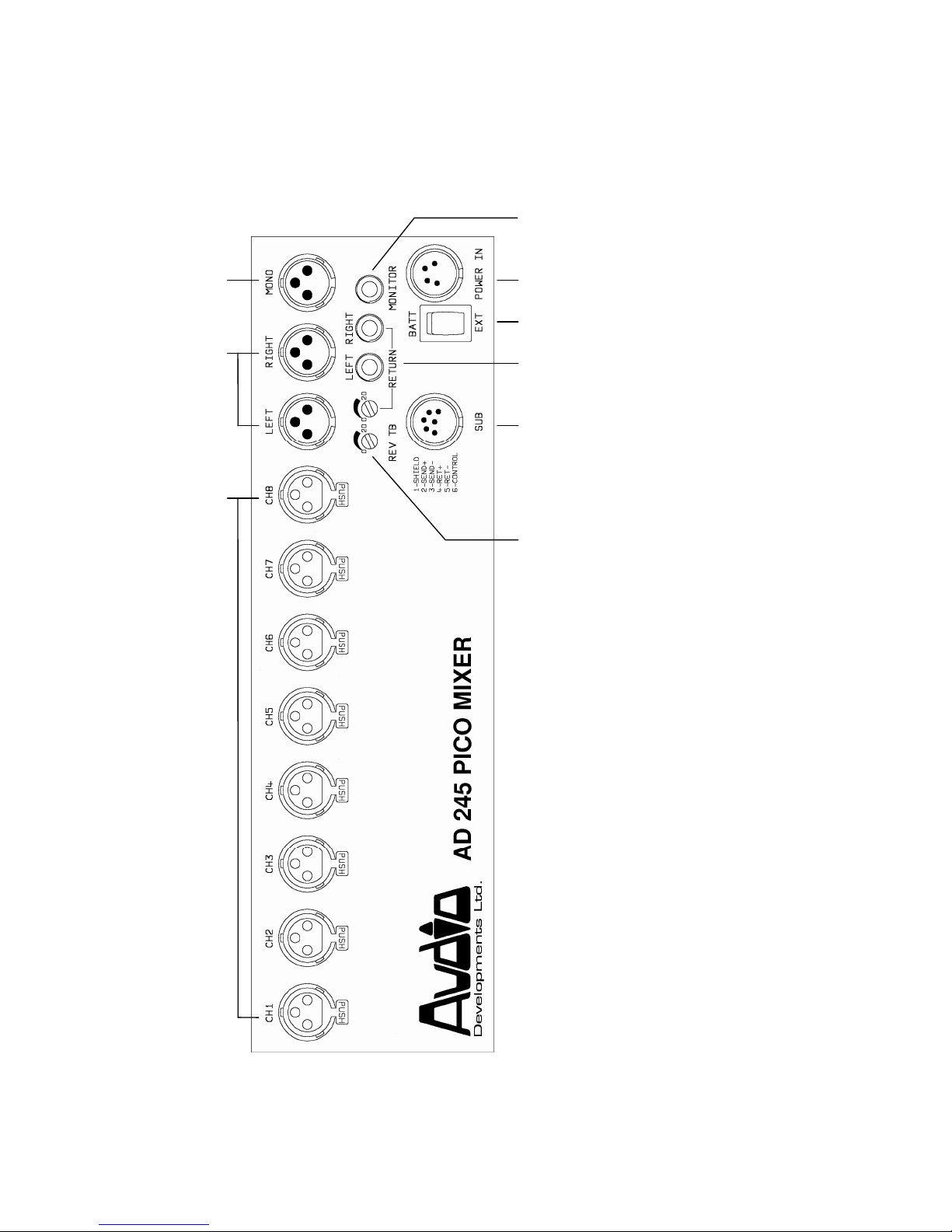
CONNECTOR PANEL
(1) Mono output XLR
(2) Stereo output XLRs (L & R)
(3) Mic/Line input XLRs
(4) Headphone monitor jack
(5) External DC power input
(6) Off/On switch (internal and
external)
(7) Stereo-return jacks (L & R)
and calibration preset
(8) Subsidiary connector
(9) Reverse talkback preset
(1)
(2)
(3)
(5)
(6)
(7)
(8)
(9)
(4)
Page 15

14
All input and output impedances and levels are to be found in the TECHNICAL
SPECIFICATION.
All inputs to, and outputs from AD245 are to be found on the connector panel.
Module connector (3) accepts balanced microphones and balanced line-level inputs.
XLR (input & output) Pin 1 Shield
Pin 2 Signal +
Pin 3 Signal -
In the case of unbalanced line-inputs and outputs, pins 1 & 3 should be connected.
This will not lead to a loss of level.
Main stereo (2) and mono (1) outputs are transformer balanced, and are at line-level.
The electronically-balanced stereo tape-return enters the mixer on two standard, ‘A’
type stereo jacks (7); left and right. Adjacent is the input calibration preset. For a
0dBu return signal, the system is calibrated when the preset is fully counter-clockwise.
From that point 20dB gain is available for lower level signals.
Unbalanced headphone monitor output appears on an ‘A’ type stereo jack (4). This
output is capable of driving 25R at 0dBu.
STEREO BALANCED JACK STEREO UNBALANCED JACK
Tip Signal + Tip Left signal
Ring Signal - Ring Right signal
Sleeve Shield Sleeve Shield
The 6-pin XLR connector, SUB (8), carries all signals to and from an outstation.
Reverse-talkback level may be set by REV TB preset (9).
XLR Pin 1 Shield Pin 4 Ret +
Pin 2 Send + Pin 5 Ret Pin 3 Shield Pin 6 Control
The unbalanced send is low impedance with a capability of driving headphones of 25
ohms impedance or greater.
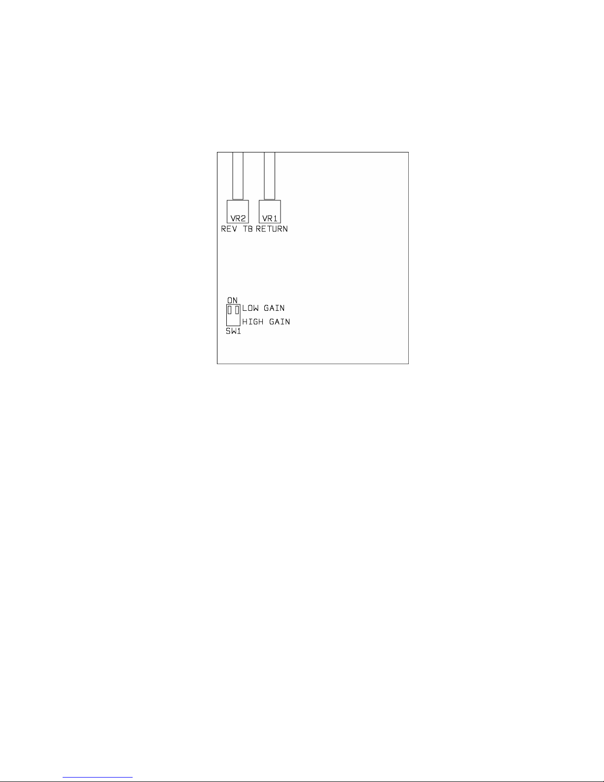
The balanced (or unbalanced) signal from the outstation may be at mic level or line
level. The mixer leaves the factory set for a line-level return, but the gain of the return
amplifier may be increased by 20dB via the DIL switch on the sub board attached to
the connector panel. Preset (9) controls the level of the return - which feeds on to the
PFL mixing buss and is routed by grounding the control line (Pin 6) at the external
source.
Thus, a two-way conversation can take place between mixer and boom operator with
the boom operator being able to listen to programme when no communication is
taking place. The programme may be selected, via a DIL switch, between the mono
output from the mixer or the signal from input channel 1 (when being used for the
Page 16
15
boom microphone). The DIL switch appears on the output module PCB. (Refer to
block diagram and line drawing in output section.) The mixer leaves the factory with
the DIL switch set in the MONO position.
A three-position rocker switch BATT/EXT (6) selects either internal batteries or an
external DC source. Power to the mixer is confirmed by the MIX ON LED on the
output module. The LED flashes when the internal voltage falls below the safe
operating level of 9v.
External powering of the mixer is via a 4-pin XLR (5).
XLR Pin 1 Ov Pin 3 NC
Pin 2 Charge Pin 4 12-15v DC
A suitable external power supply is Audio Developments’ AD100-09 but any external
DC source must be capable of delivering 750mA at 12v.
Page 17
16
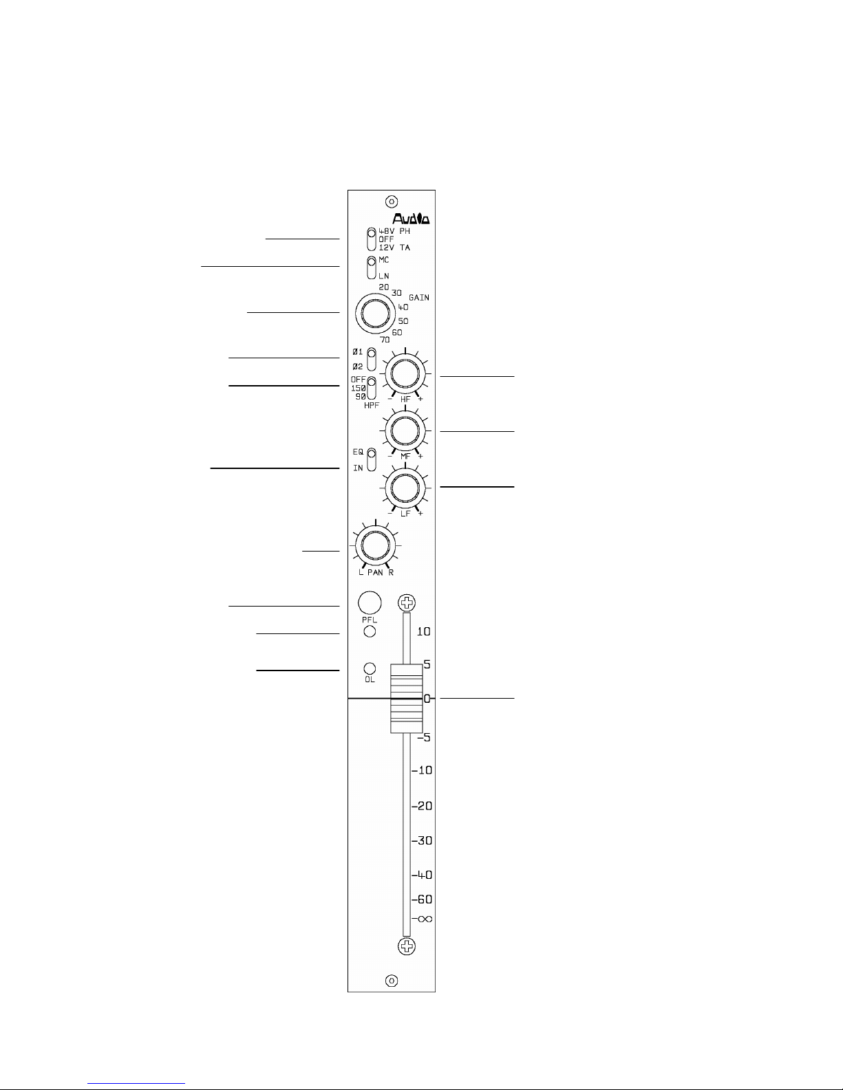
MICROPHONE/LINE INPUT MODULE
(1) Microphone power
(2) Line input
(3) Input-gain control
(4) Phase change
(5) High-pass filter
(6) EQ Selector
(7) Panoramic potentiometer
(8) Pre-fade listen
(9) PFL indicator LED
(10) Overload indicator
(11) High-frequency control
(12) Mid-frequency control
(13) Low-frequency control
(14) Channel fader
Page 18

17
The Microphone/Line input module functions are as follows: Switch (1) selects 48v
phantom and 12v tonader power for condenser microphones. Powering may be
selected before or after connecting the microphone, but switch off all powering on
unterminated modules to ensure unconditional stability of the mixer. For complete
safety of external equipment, switch off microphone power before connecting a linelevel signal.
Phase change (4) is pre transformer and operates on microphone and line inputs.
is the normal position.
The high-pass filter is pre transformer and, similarly, operates on microphone and line
inputs. In this position the filter protects the transformer from low-frequency saturation
caused by wind, traffic, air conditioning etc. Operating frequencies are to be found in
the TECHNICAL SPECIFICATION. The high-pass filter operates independently of
the equaliser.
The input gain of the microphone amplifier is set by the 6-position switch (3). The
range of this control is 50dB in 10dB steps. For line-level signals, an input attenuator
is inserted via switch (2).
Following the microphone amplifier is the simple, but effective, equaliser which has
been retained from the original PICO - selector switch (6). Because of the inherent
inaccuracy of the centre-detent mechanism, it is not Audio Developments’ practice to
fit such devices to equaliser amplitude controls - HF (11), MF (12), LF (13).
A panoramic potentiometer - panpot - (7) routes the module’s signal proportionately
between the left and right mix busses.
Pre-fader listen (8) with its LED indicator (9) routes the module’s signal to the
monitor/PFL mix buss for auditioning on headphones.
An overload LED (10) illuminates 3dB before clipping at the input to the fader.
The Penny & Giles fader (14) is calibrated 10dB from its fully open position,
allowing the operator to work with 10dB of gain in reserve. Faders on adjacent
modules can be coupled for stereo operation by the use of standard ganging clips.
Page 19
18
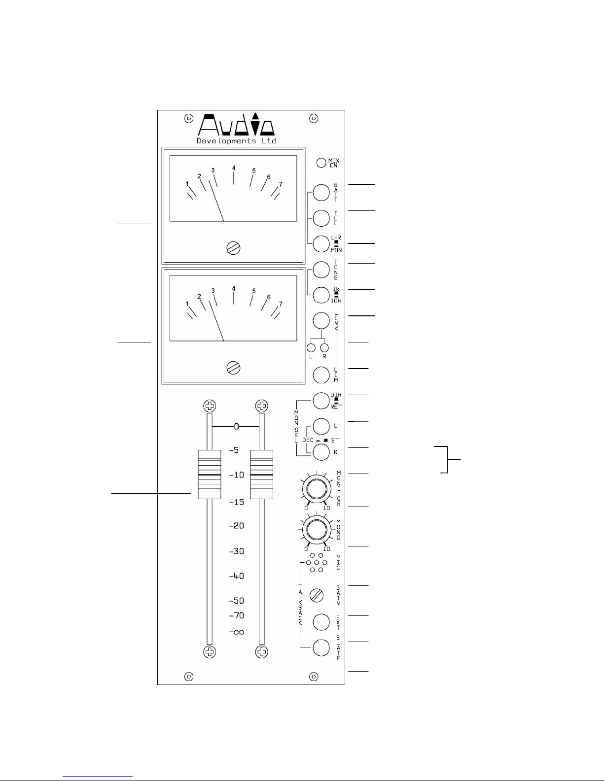
OUTPUT MODULE
(1) Meter 1
(2) Meter 2
(3) Output
faders
(4) Mixer ON LED
(5) Battery indicator
(6) Meter illumination
(7) L-R or MON to meters
(8) Line-up tone
(9) 1kHz or 10kHz line-up tone
(10) Limiter link
(11) Limiter LEDs
(12) Output limiters
(13) Direct or Return to HP
(14) Left only
(15) Right only
(16) Monitor output-level
(17) Mono output-level control
(18) Internal microphone
(19) Internal-microphone level
control
(20) Talkback send
(21) Slate
Matrix
Page 20
19
This module controls the level of main and monitor output signals and metering of the
output and monitor signals (including PFL). Calibration is achieved when the output
faders (3) are at maximum.
The upper meter (1) reads left output, the lower meter (2) right output when switch (7)
is in its L-R position. In MON position the meters read either mono output or monitor
output. This is determined by a set of links on the main printed circuit card of the
output module. The factory setting, with switch (7), set to MON is both meters read
mono output. Refer ADJUSTMENTS & CALIBRATION section for instructions on how
to convert the MON position of switch (7) to enable the meters to read monitor output.
Battery status is read on the upper meter by BATT (5) and the meters may be
illuminated by ILL (6) - overuse of this function will rapidly drain the batteries. When
the internal voltage drops below a safe operating level, the MIX ON indicator LED (4)
will flash.
The main output signal is metered and monitored after the output faders and limiters.
The monitor signal is metered before its level control.
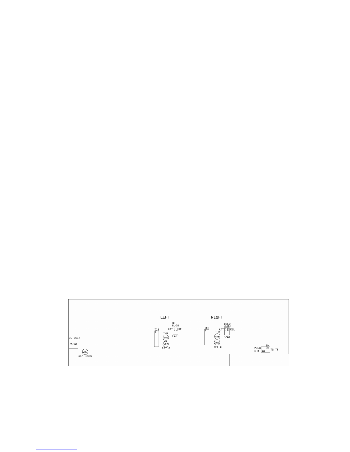
A pair of limiters may be switched in to the main output - LIM (12) - and linked for
stereo operation - LINK (10). LEDs (11) indicate when limiting is taking place. A
choice of fast or slow attack and release times may be made via the two DIL switches
on the output printed circuit board. When the limiters are being used as a stereo pair,
they should have their attack times and release times set identically. The factory
setting for the DIL switches is SLOW.
OUTPUT MODULE PRINTED CIRCUIT BOARD
Page 21

20
Line-up tone, when selected (8), replaces the normal signals on the main output.
The frequency of the line-up tone may be selected between 1kHz and 10kHz (9).
Line-up tone is calibrated on the (BBC-scaled) meters to PPM4, giving a line-output
level of 0dBu with the output faders set to maximum.
The remaining controls are associated with headphone-monitoring of signals from the
mixer - internal signals (DIR) or tape-return (RET) may be selected (13): these signals
may be either in the L-R domain or the M-S domain. When switches (13), (14) and
(15) remain unselected the main-output signal from the mixer appears on the
headphones. If SW (14) is selected, the left-output signal appears on both earpieces;
if SW (15) is selected, the right-output signal appears on both earpieces. If switches
(14) + (15) are selected, a matrix amplifier is inserted across the monitor output:
when the main output is in the L-R domain, the matrix will enable mono compatibility
to be assessed on the left earpiece and out-of-phase components to be checked on
the right earpiece. When working entirely in the M-S domain, the matrix will transform
the mixer output into the L-R domain for monitoring purposes. Selection of RET (13)
will allow these functions to be performed on a tape-return signal. The level of the
monitor signal is controlled by potentiometer (16).
A mono mixdown of the main, stereo output from the mixer is available and its level is
adjusted by MONO (17).
The signal from the internal microphone (18) replaces any other signal appearing at
the outstation when routed via EXT (20) - the level being set by preset GAIN (19).
SLATE (21) allows the mixer operator to ADD a voice signal to the main stereo output
together with a low-frequency identification tone (100Hz).
When PFL is selected on an input channel or when the outstation wishes to
communicate with the mixer operator (by grounding pin 6 on the multiway), logic
changes the signal on monitor output accordingly.
Page 22
21
ADJUSTMENTS AND CALIBRATIONS
Meters - are to broadcast specification and either a VU or a PPM may be selected. A
choice of 3 scales is available for the PPM: BBC, N10, SDR.
Line-up-tone oscillator - the preset (VR6) that adjusts its level at the output of the
mixer is mounted on the output module printed circuit board.
Low-battery indicator - the preset (VR10) associated with this facility is also mounted
on the output module printed circuit board. The low reading is set at the factory and
corresponds to a set of batteries having discharged to 9v. On a VU meter, low volts is
at 0VU. On a PPM meter it is indicated by a separate marking: yellow on a BBC
scale and red on an N10 and SDR scale.
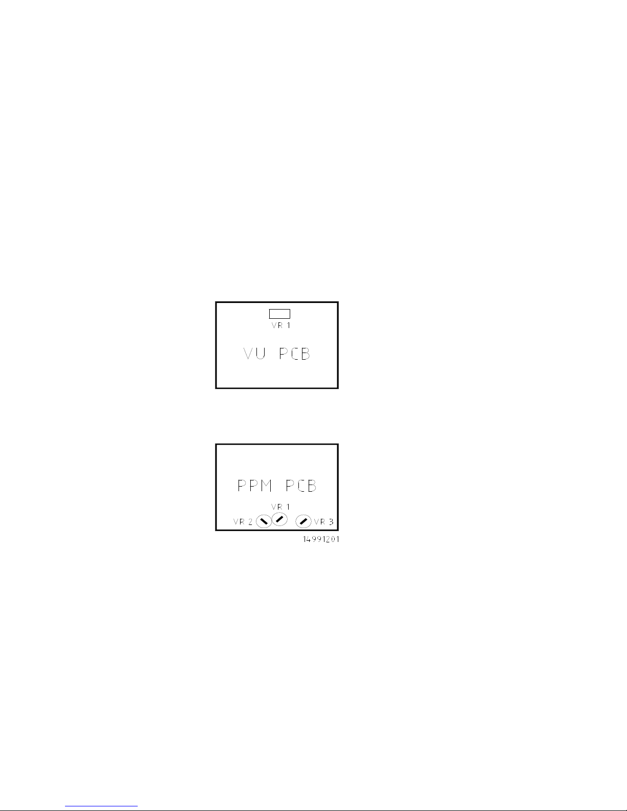
VU meter - there is one preset, on the VU meter PCB, for meter adjustment. Set an
input module for a line input and introduce a 1kHz tone from an audio signal
generator. Adjust levels to achieve a reading of +4dBu, at a main output, on an AC
millivoltmeter - measured across pins 2 & 3 on the output XLR. Select the meters to
L-R and adjust the preset to give a reading of 0VU.
PPM meter - the driver PCB has three calibration controls (presets).
VR1 adjusts the reference level, VR2 and VR3 adjust the 'law' of the meter.
VR2 adjusts the upper sector of the scale and VR3 adjusts the lower sector.
To initiate calibration, set each preset to its mid position.
Page 23
22
BBC scale - using the tone generator and millivoltmeter as described above, adjust
mixer levels for a reading of 0dBu, on the millivoltmetez, from a main output. Select
the meters to L-R and adjust VR1 for a reading of 4. Increase the output signal to
+8dBu and adjust VR2 for a reading of 6. Decrease the output signal to -8dBu and
adjust VR3 for a reading of 2. Repeat this procedure until an accurate set of readings
is obtained without further adjustment to any of the presets being required. Now
check all points 1 to 7 on the scale to determine whether they are within specification.
N10 scale - for a meter calibration of TEST = 0dBu. With a main-output signal
of -6dBu, adjust VR1 to give a meter reading at -6. Increase the signal to +6dBu and
adjust VR2 to obtain a meter reading at +6. Lower the output signal to -18dBu and
adjust VR3 to obtain a meter reading at -18. Repeat this procedure to obtain an
accurate reading at each of these three points. Now check the calibration of all meter
points.
SDR scale - with a main-output signal level of -6dBu, adjust VR1 to obtain a reading
of -12. Increase the output signal to +6dBu and use VR2 to obtain a reading of 0 on
the meter. Lower the output signal to -18dBu and adjust VR3 to give a reading of -
24. Repeat the procedure to obtain an accurate reading at each of these three points.
Now check the calibration of all meter points.
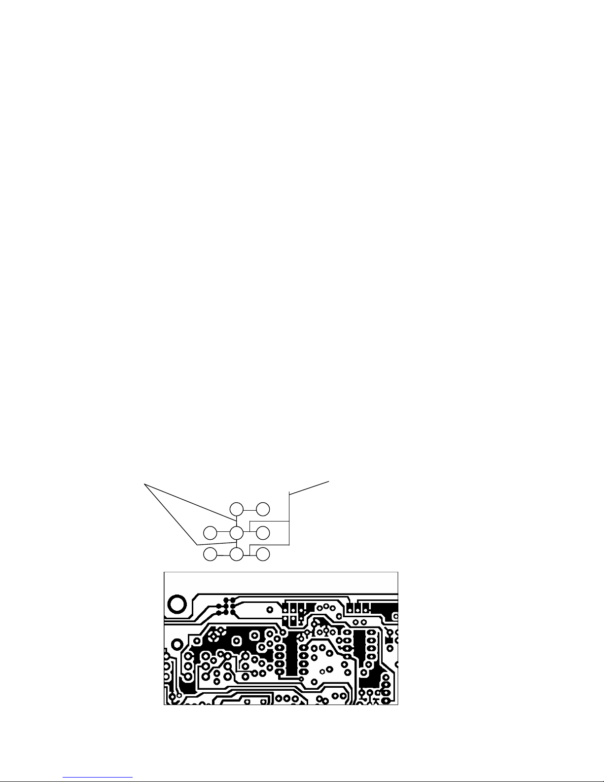
L-R/MON switch - To enable the meters to read monitor output rather than mono
output when in the MON position a set of links on the main printed circuit card of the
output module have to be broken and another set of links made.
Referring to the diagrams below. Shown is the section of the printed circuit card
containing the link mechanism. Cut links marked ‘X’ and add links in the places
marked ‘Y’. It may be necessary to clear the solder mask from the printed circuit pads
before new links (Y) can be soldered into place.
X (cut) Y(add)
Page 24

23
Main-output limiters - calibration involves two presets per output.
Using the 'L' output as the example …
Biasing and threshold are adjusted as follows: VR5 biases the limiter circuit to the
point of correct operation and VR4 sets the threshold. (Labelled SET 0 and THR
respectively.)
With no signal present, VR5 should be adjusted to give a reading in the
range
-1.5v to -2.5v at PIN 8 of IC 2. VR4 should be adjusted to give a reading in the
range -2.5v to -3.5v at PIN 12 of IC2.
Apply a signal at 1kHz to the mixer to give a level of 0dBu at 'L' output. Then select
the limiter function and adjust VR5 until the output signal starts to fall (typically
0.2dB). The DC voltage at PIN 8 of IC 2 should be approximately -2.0v.
After setting VR5, adjust the output signal to just greater than +8dBu with the limiter
deselected. Introduce the limiter and adjust VR4 until the output signal falls to
+8dBu. This is the THRESHOLD setting. (If a different threshold setting is required,
alter the signal levels accordingly.) The DC voltage at PIN 12 of IC 2 should be
approximately 0.6v different from that at PIN 8.
The right output can be set using the above procedure, but the preset and IC numbers
change to correspond with the output being calibrated.
The link function has no individual setting of its own. To ensure this works within
specification it is important that L and R outputs are set up as a pair. After following
the above procedure, the DC voltages at PINS 8 and PINS 12 of the ICs
should be identical. (Tolerance 0.05v with typical figures at PIN 12 of -2.6v and
PIN 8 of -2.0v)
There are two DIL switches associated with the attack and release times: one for the
left output, the other for the right output.
Page 25

24
POWER SUPPLY UNIT
TYPE AD100-09
The AD100-09 mains POWER SUPPLY UNIT is suitable for driving most of
AUDIO DEVELOPMENTS’ range of portable audio mixers. This PSU is a single-rail
device providing 500mA of current at +14v DC potential and is used as a substitute for
battery power with mixers containing an internal DC-DC converter.
The AD100-09 may be powered from either a 110/120v AC source or a 220v/240v AC
source. Ensure that the AC Voltage Selector Switch on the front panel is in the
correct position for the source in use. Operating the equipment at the wrong voltage
could be hazardous. Care must be taken to connect the LIVE, NEUTRAL and
EARTH pins of the PSU’s IEC mains connector to the corresponding terminals
associated with the AC source. The ON/OFF switch contains an indicator that
illuminates when the PSU is operational.
FOR SAFETY REASONS, AD100-09 POWER SUPPLY UNIT MUST BE
CONNECTED TO MAINS EARTH. Any maintenance to the PSU or its mains cable
assembly should be performed by a qualified engineer.
CHARGING: If nickel-cadmium cells are fitted in an AD140 series mixer, they may
be recharged in situ from AD100-09 power supply - whether the mixer is in use or not.
(Maximum current is set at 250mA - in addition to the 500mA of current supplying the
audio electronics.) The charging circuit has its own ON/OFF slide switch and LED
indicator. DO NOT ACTIVATE THE CHARGE CIRCUIT UNLESS THE MIXER IS
FITTED WITH NICKEL-CADMIUM CELLS.
FUSES: Two 20mm ANTI-SURGE fuses protect AD100-09 against fault conditions.
Should either fail, it is strongly recommended that the cause be traced. Refer to the
TECHNICAL LIBRARY. Only suitably qualified personnel should service the power
supply unit. The fuse holder on the front panel contains the mains fuse.
For continued safety the specified fuse link must be fitted in the mains fuse holder
when a replacement is required. Ensure it is of a type approved by a National
Approved Body.
DC-OUTPUT XLR PIN 1 Ov PIN 3 NOT CONNECTED
PIN 2 CHARGE PIN 4 +14vDC
DO NOT REMOVE THE OUTER COVERS
NOTE: The power supply unit should be serviced by a suitably qualified engineer.
Only genuine spare parts with identical specification must be used.
It is DANGEROUS to change the specification or modify the product in any way.
CUSTOMER NOTES AND FACTORY MODIFICATION
250mA HRC TYPE T 240v AC
Page 26

25
TECHNICAL LIBRARY
 Loading...