

Page 1
REVISED APRIL ‘02
System Design
&
Technical Documentation
602-610 Mamaroneck Avenue, White Plains, NY, 10605, www.ada-usa.com, 1-800-HD-AUDIO, Fax (914) 946-9620
Page 2

Contents
Suite 16 Modules ........................................................................ 2
A-16 Audio Input Module............................................................ 3
PP-1200 Phono-Preamplifer.................................................................................. 5
Paging Features.......................................................................... 8
P-16 Preamplifier Module ............................................................ 9
Power Amplifier Options ........................................................... 12
Home Theater (or Recording) Set Up ......................................... 16
Amp Trigger Jumping on 9-Pin D Connectors ........................... 17
V-16 Video Switching Module ................................................... 18
AVP-16 Baud Rate, Zone, & Paging Settings.............................. 20
AVP-16 Configuration Options .................................................. 22
Matrix Switching - S-Video, Component, or RGBHV.................... 23
AVP-16 Slave-Unit Configuration Options.................................. 25
AVP-16 Slave-Unit Setup ........................................................... 26
AVP-16 Main & Slave Unit Power-On Setup................................ 27
AVP-16 ADA Bus & Control Wiring ............................................ 28
Damaged Wiring Options .......................................................... 30
CAT-Link and ADA Bus Wiring ................................................... 30
IR Repeating............................................................................. 30
IR Control of the Suite 16 ......................................................... 31
RF Control ................................................................................ 32
MC-6000 Keypad with Video, WH-6000, & TV-6000................... 34
CMB-1 Clock Module ................................................................. 36
MC-5011 Keypad Setup ............................................................. 37
MC-5000 Keypad LED Setup ...................................................... 38
MC-5000 Keypad Manual Setup................................................. 39
MC-5000 Installer Setup ............................................................ 41
RS-232 Connections for PC’s & Control Systems.......................... 48
Keypad Uploader Program (MC-5KS Uploader) .......................... 49
Suite 16 Testing & Program ....................................................... 54
Suite 16 Serial Protocol V1.4 Explanation ................................ 64
Suite 16 Video Card V1.1 or V1.2 Protocal Explanation............. 81
Suite 16 ASCII Codes................................................................. 84
Appendix A - MC-5000 Setup Flow Charts ................................. 87
Appendix B - System Specifications ........................................... 94
Appendix C - 9 Pin D Connector Information ............................. 95
All specifications subject to change without prior notice.
©2002 Audio Design Associates, Inc. All rights reserved.
- 1 -
Page 3
Suite 16 Modules
Suite 16 is appropriately named as it is a system that is built using a suite of modules and
components. These modules and other components allow extraordinary flexibility in the design of a distributed entertainment system. This section will focus on the three modules that
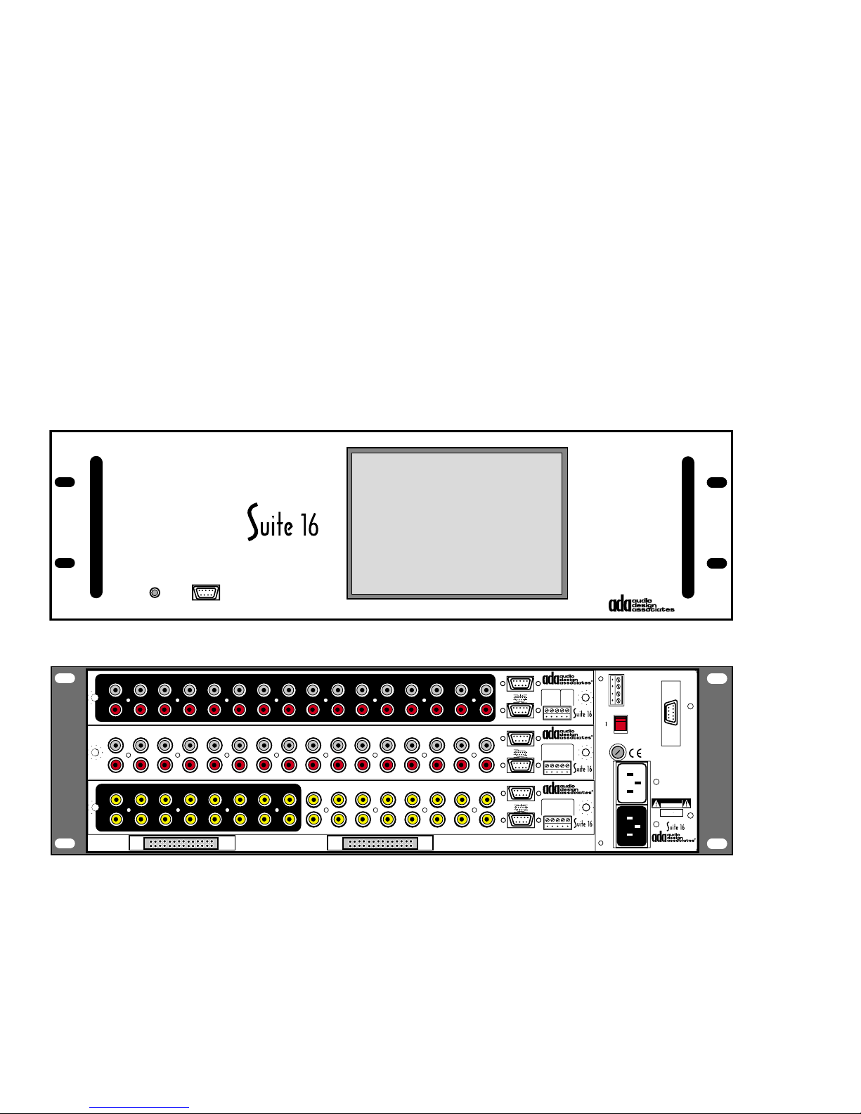
are inserted into the Suite 16 Multi-Room (MR) Controller Chassis, the AVP-16.
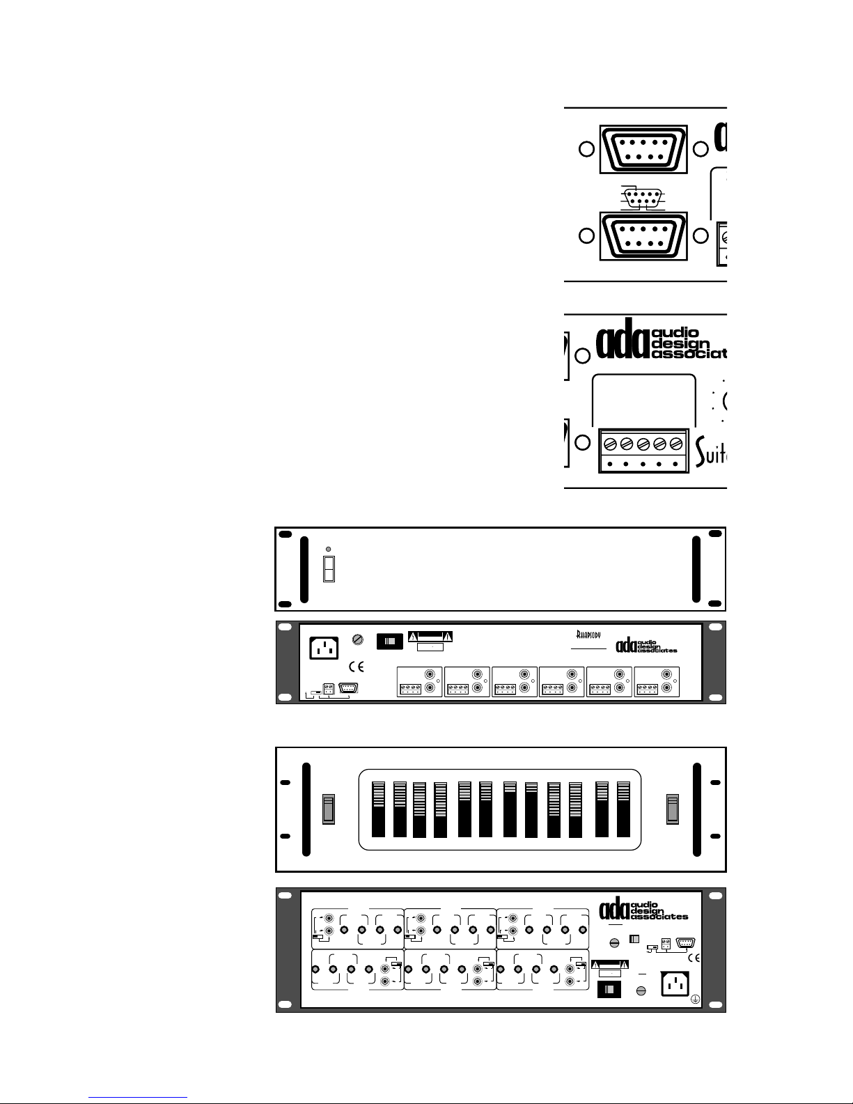
AVP-16 Multi-Room (MR) Controller Chassis
The AVP-16 is a chassis that can hold up to three Suite 16 Modules. Several AVP-16s can be
used in a single system. The AVP-16 features a front panel power/reset switch, front panel
RS-232 9-Pin “D” style connector, and a removable plexi-glass window. This window will
permit access to Suite 16 Module adjustment controls as well as permitting Suite 16 Module
Status LEDs to be seen during normal operation.
POWER RS-232
AVP-16
1
2 3 4 5 6 7 8 9 10 11 12 13 14 15 16
L
R
1
2 3 4 5 6 7 8 9 10 11 12 13 14 15 16
L
R
13579111315
2 4 6 8 10 12 14 16
VIDEO INPUTS
EXPANSION PORTS
A-16
P-16
13579111315
V-16
2 4 6 8 10 12 14
Input Triggers
In 1-8
In 9-16
Zones 1-6
Zones 7-12
Out 1-8
16
Out 9-16
In 7/15
In 6/14
In 5/13
In 4/12
In 3/11
+12VDC Outputs
Zones 1- 6 & 7-12
TO PTM-1225/1260
In 6/12
In 5/11
In 4/10
In 3/9
+12VDC Outputs
Output Triggers
Out 7/15
Out 6/14
Out 5/13
Out 4/12
Out 3/11
+12VDC Outputs
A-16 • Audio Input Module
Balanced
In 8/16
Audio Page
Gnd
Input (600Ω)
In 1/9
1
2
In 2/10
(+)3(-)4(+)5(-)
Com
Paging Input/Trigger
P-16 • Preamplifier Module
Zones 13-16
Gnd
+12VDC Output
In 1/7
Gnd
In 2/8
(-)13(+)14(+)15(+)16(+)
V-16 • Video I/O Module
Programmed Video
Out 8/16
Input Triggers
Gnd
5-24V AC•DC
Out 1/9
Gnd
Out 2/10
(-)1(+)2(+)3(+)
Input Triggers
Trigg er
5-24V
AC•DC
ADA Bus®
230V
115V
1/2 ASB
115V~
1/4 ASB
230V~
Switch
AC
(10A)
4
(+)
Main
AC
Input
Network Control I/O
1 Gnd
2 Fdbk
3 Cntrl
4 +V
115 V
WARNING! Risk Of Hazardous Energy!
Make Proper Connections.
AVERTISSEMENT! Energie Electrique
Dangereuse!
Faire Des Connexions Propres
Pour L'Hautparleur.
Voir La Notice De Fonctionnement.
CAUTION: Disconnect Supply
Cord Before Servicing.
ATTENTION: Debrancher
Avant Le Depannage.
115V~/60Hz • 230V~/50Hz
500 WATTS MAX
CAUTION
RISK OF ELECTRIC SHOCK
DO NOT OPEN
ATTENTION!
RISQUE DE CHOC ELECTRIQUE.
NE PAS OUVRIR
MADE IN U.S.A.
AVP-16 MR Controller
The Suite 16 is completely modular including the Power Supply and Control I/O section. The
Power-Control Module slides in from the back of the AVP-16 chassis and can be removed in
the event service is required.
The back of the AVP-16 also features two Expansion ribbon cable connections. These are
only used when multiple AVP-16s are employed on a single project.
- 2 -
Page 4
A-16 Audio Input Module
n
(
2
+
Only one A-16 Audio Input Module is used per Suite 16 System.
Input Triggers
1
2 3 4 5 6 7 8 9 10 11 12 13 14 15 16
L
R
A-16
Audio Inputs
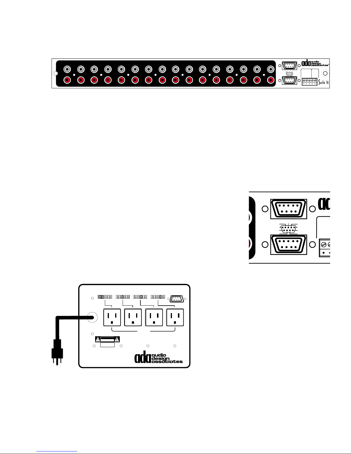
The A-16 features 16 stereo RCA jacks which are the sixteen audio inputs to the system.
Input Level Trim Control
By and large most audio source components put out audio signal levels that are close to each
other. However, some sources run significantly louder while other sources are significantly
softer. This becomes an issue as you change inputs in a room, as volume levels can vary
between selected components, even though the room’s volume control has not been altered.
To compensate for varying output levels between source components, the Suite 16 System
permits a different input level for each of the sixteen audio inputs. This feature is set in
software.
Input Tracking Low Voltage Triggers
In 1-8
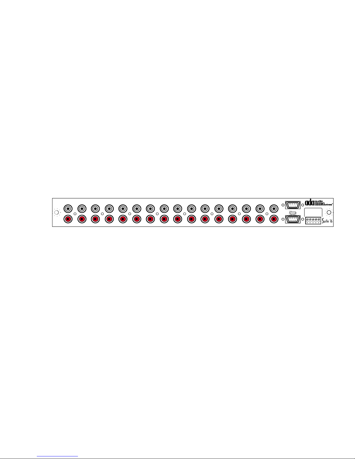
The A-16 also features two 9-pin “D” style connectors (non-RS-
232). The top connector includes a common ground pin and
then eight other pins corresponding to inputs 1-8. The bottom
connector also features a common ground pin and eight connectors which correspond with inputs 9-16. When an input is
selected, its corresponding pin produces a 12VDC output. This
In 9-16
trigger can be used to activate a source component function.
In 1-8
In 7/15
In 8/16
In 6/14
Gnd
In 5/13
In 1/9
In 4/12
In 3/11
In 2/10
In 9-16
+12VDC Outputs
Paging Input/Trigger
Input Triggers
In 7/15
In 6/14
In 5/13
In 4/12
In 3/11
In 8/16
Gnd
In 1/9
In 2/10
+12VDC Outputs
A-16 • Audio Input Module
Balanced
Trigg er
Audio Page
5-24V
Input (600Ω)
AC•DC
2
1
(+)3(-)4(+)5(-)
Com
A-16
Bala
Audio
Input
1
Com
Paging
(
When using ADA’s ACC-48 Source Compo-
nent AC Switcher, these two connectors can
Set Shunting Pins To Engage AC With Zone Or Source Numbers 1-8
120-240 VAC
50-60 Hz
12345678
3421
TO 9 PIN "D"
DELTA-88123456781234567812345678
be attached to up to two ACC-48s each. This
will provide AC component switching (based
on activity) for as many as sixteen source
components. As with most every ADA System, Suite 16 permits the AC to be removed
from source components when they are not
being used. This is intended to preserve the
life of the device as even standby-power is
removed when the component is not in use.
CAUTION
RISK OF ELECTRIC SHOCK
DO NOT OPEN
ATTENTION!
RISQUE DE CHOC ELECTRIQUE.
NE PAS OUVRIR
MADE IN U.S.A.
ACC-48
QUAD AC CONTROLLER
1000 WATTS
MAX TOTAL
1. Delta-88 9 Pin "D" programmed for source AC control. - Set one shunting
pin per AC outlet according to source inputs. Set 3 pins for MT-3000.
2. Delta-88 9 Pin "D" programmed for zone AC control. - Set one shunting
pen per AC outlet according to zone numbers. Set all shunting pins on
one AC Outlet for All-On source AC control when not using an ACC-3000.
This may not be an option for devices with
built-in clocks or devices that require AC at
all times.
Please note, that each switched outlet on the ACC-48 is limited to 2.5 amps.
- 3 -
Page 5
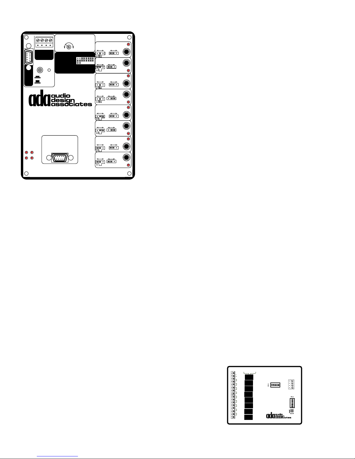
The two low voltage triggers can also be used to engage an “On” and an “Off” IR command when using
ADA’s IRL-5000 to control source components.
The IRL-5000 is an advanced version of ADA’s IRL-
3000 Infrared Learner and uses the same PC software program to capture, test, layout, and label IR
commands from standard source components. While
the IRL-5000 is used on Suite 16 Systems when employing ADA keypads (so that the keypads transport
function buttons can control the source components),
the IRL-5000 can also be controlled serially making it
an ideal component to add to a Suite 16 even if no
ADA keypads are being used. A single IRL-5000 can
operate as many as eight source components. Two
IRL-5000’s can be used to control sixteen components
when set to different addresses. The IRL-5000 has
1 2 3 4
Gnd Rx Tx +15V
ADA Bus®
ADA/232
RS-232
Pins
RS-232
2=Tx
3=Rx
ADA Bus
5=Com
IRL-5000
Source Controller
Power On/Off IR Macro
Connect To Mainframe
PGM DEL
CON ERR
Source DC Triggers &
ACC-48 AC Controllers
IR Repeating Only
40KHz IR Repeat
Frequency
12345678Source Ports:
Data/Carrier
IR Flasher=Remove Jumper
Serial Direct=Insert Jumper
Repeater
IR - Serial
Repeater
IR - Serial
Repeater
IR - Serial
Repeater
IR - Serial
Repeater
IR - Serial
Repeater
IR - Serial
Repeater
IR - Serial
Repeater
IR - Serial
Off
Off
Off
Off
Off
Off
Off
Off
Serial
Data Only
Norm Invert
Serial
Data Only
Norm Invert
Serial
Data Only
Norm Invert
Serial
Data Only
Norm Invert
Serial
Data Only
Norm Invert
Serial
Data Only
Norm Invert
Serial
Data Only
Norm Invert
Serial
Data Only
Norm Invert
1
2
3
4
5
6
7
8
nine address settings.
The IRL-5000 features two 9-pin “D” connectors. The connector on the upper left side is used
for programming and is connected to a PC. The connector at the bottom of the IRL-5000 is
wired in parallel with the ACC-48(s). By using this feature of the IRL-5000, one can initiate an
IR signal or sequence (macro) when a source is first selected and also initiate an IR signal or
sequence when that source is no longer being used. Since the IRL-5000 permits the use of
delays, you can use both the ACC-48 and IRL-5000 together such that as a source is selected, it gets AC from the ACC-48 and then is issued a command (i.e. play). Another option
for DSS receivers would involve programming the OFF function with a macro to reset the
DSS receiver to the favorite music channel. Thus, every time the DSS is no longer being
used on the system, the IRL-5000 resets it to this station. When it is again selected, the
favorite channel is already tuned in. This permits one button operation while completely
removing AC from the component when it is no longer being used.
Naturally, one can simply use the IRL-5000 without employing ACC-48s. When using an ADA
Trinity Tuner, ADA recommends using at least one IRL-5000.
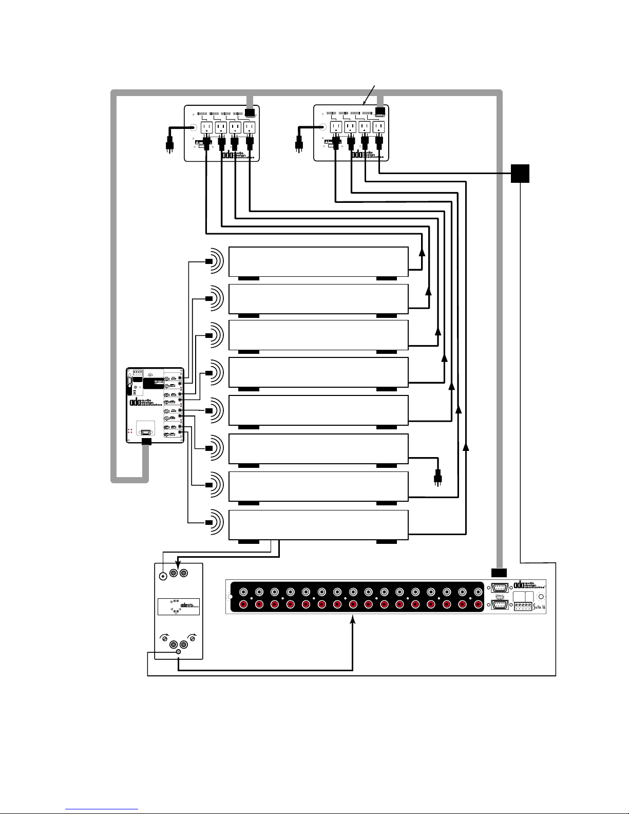
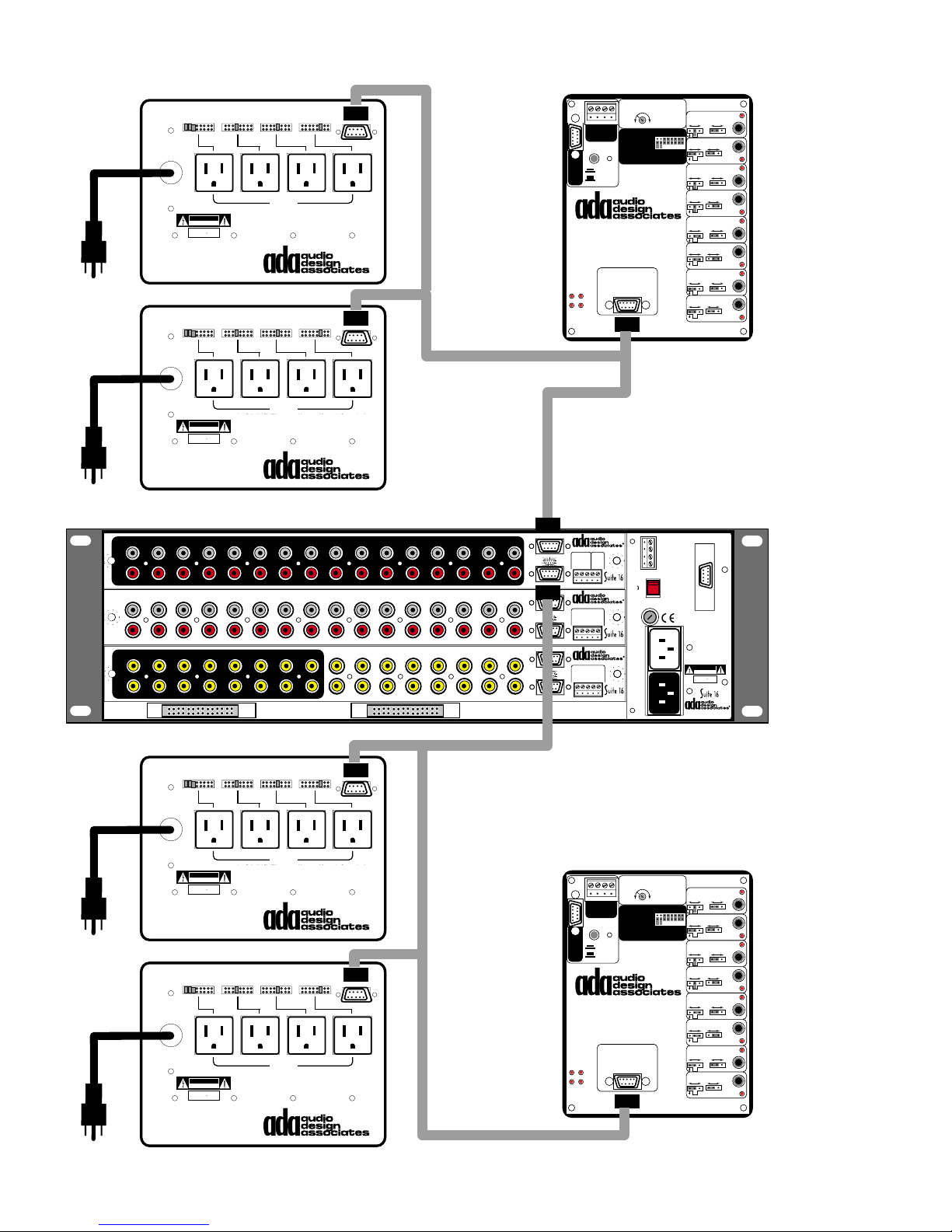
The diagrams on the next two pages show an IRL-5000 employed with two ACC-48s. The
diagram on page 6 details the complete sixteen source system with two IRL-5000s and four
ACC-48’s.
LVI-3800 Low Voltage Relay
The LVI-3800 is used when controlling source components that
are not capable of control via either serial or IR control interfaces.
Older sources or for example, slide projectors fall into this category. The LVI-3800 features eight relays which close momentarily when transport buttons are pressed on the MC-5000, MC3000, and MC-3800 keypads. The LVI-3800 is an ADA Bus device and connects to an open ADA Bus jack on any wire harness.
- 4 -
+12V
+5V
-
R1
R2
R3
R4
R5
R6
R7
R8
NORM. OPENNORM. CLOSED Carefully remove and insert relays
for changing from the Normally Open
to the Normally Closed position.
RELAY 1
SW 2
RELAY 2
ON
8 7 6 5 4 3 2 1
RELAY 3
RELAY 4
LVI-3800
LOW VOLTAGE RELAY
RELAY 5
RELAY 6
RELAY 7
RELAY 8
ADA BUS™
SW 1
NORM
4
3
2
1
ON
8
7
6
5
4
3
2
1
RX/TX
SET
REV
Page 6
ACC-48 OUTLET 3 (PHONOGRAPH)
& OUTLET 4 (PHONO-PREAMP)
SET TO TURN ON TOGETHER
OUTLET
IRL-5000
IR Repeating Only
40KHz IR Repeat
1 2 3 4
Gnd Rx Tx +15V
ADA Bus®
Data/Carrier
ADA/232
IR Flasher=Remove Jumper
Serial Direct=Insert Jumper
RS-232
Pins
RS-232
2=Tx
3=Rx
ADA Bus
5=Com
IRL-5000
Source Controller
Power On/Off IR Macro
Connect To Mainframe
Source DC Triggers &
PGM DEL
ACC-48 AC Controllers
CON ERR
TO AC
Repeater
Serial
Frequency
IR - Serial
Data Only
12345678Source Ports:
Norm Invert
Off
Repeater
Serial
IR - Serial
Data Only
Norm Invert
Off
Repeater
Serial
IR - Serial
Data Only
Norm Invert
Off
Repeater
Serial
IR - Serial
Data Only
Norm Invert
Off
Repeater
Serial
IR - Serial
Data Only
Norm Invert
Off
Repeater
Serial
IR - Serial
Data Only
Norm Invert
Off
Repeater
Serial
IR - Serial
Data Only
Norm Invert
Off
Repeater
Serial
IR - Serial
Data Only
Norm Invert
Off
Set Shunting Pins To Engage AC With Zone Or Source Numbers 1-8
120-240 VAC
50-60 Hz
ACC-48
QUAD AC CONTROLLER
1
2
3
4
5
6
7
8
1. Delta-88 9 Pin "D" programmed for source AC control. - Set one shunting
pin per AC outlet according to source inputs. Set 3 pins for MT-3000.
2. Delta-88 9 Pin "D" programmed for zone AC control. - Set one shunting
CAUTION
RISK OF ELECTRIC SHOCK
pen per AC outlet according to zone numbers. Set all shunting pins on
DO NOT OPEN
one AC Outlet for All-On source AC control when not using an ACC-3000.
ATTENTION!
RISQUE DE CHOC ELECTRIQUE.
NE PAS OUVRIR
MADE IN U.S.A.
TO 9 PIN "D"
12345678
DELTA-88123456781234567812345678
3421
1000 WATTS
MAX TOTAL
Set Shunting Pins To Engage AC With Zone Or Source Numbers 1-8
120-240 VAC
50-60 Hz
1. Delta-88 9 Pin "D" programmed for source AC control. - Set one shunting
2. Delta-88 9 Pin "D" programmed for zone AC control. - Set one shunting
CAUTION
RISK OF ELECTRIC SHOCK
DO NOT OPEN
ATTENTION!
RISQUE DE CHOC ELECTRIQUE.
NE PAS OUVRIR
MADE IN U.S.A.
ACC-48
QUAD AC CONTROLLER
TO AC
OUTLET
12345678
3421
1000 WATTS
MAX TOTAL
pin per AC outlet according to source inputs. Set 3 pins for MT-3000.
pen per AC outlet according to zone numbers. Set all shunting pins on
one AC Outlet for All-On source AC control when not using an ACC-3000.
TO 9 PIN "D"
DELTA-88123456781234567812345678
9 PIN RIBBON
CABLE WITH
9 PIN "D"
CONNECTOR
FOR SOURCE
AC TRIGGERS
12VAC
X-FORMER
FOR
PP-1200
PHONO
PREAMP
FM 1
FM 2
CD 1
CD 2
CASSETTE
VCR
DVD
AC
PHONOGRAPH
LINE
CORD
GROUND WIRE
AUDIO CABLE
In 1-8
In 6/14
In 5/13
In 4/12
In 3/11
In 9-16
+12VDC Outputs
Input Triggers
In 7/15
A-16 • Audio Input Module
Balanced
In 8/16
Audio Page
Gnd
Input (600 )
In 1/9
1
In 2/10
Com
Paging Input/Trigger
2
(+)3(-)4(+)5(-)
Trigger
5-24V
AC•DC
PP-1200
PHONO
PREAMP
DC
POWER
LR
GND
INPUT
Phono Input
Ground Post
L
R
PP-1200
Phono Preamplifier
LR
Gain R
Gain L
Phono Preamp Output
12VAC Power
OUTPUT
L
R
GAIN GAIN
120VAC
1
2 3 4 5 6 7 8 9 10 11 12 13 14 15 16
L
R
AUDIO CABLE
A-16
PP-1200 Phono-Preamplifer
If you still enjoy playing records, there is no reason not to be able to access them through your
whole-house Suite 16 System. Most turntable use a moving-magnet cartridge which requires
special preamplification. The PP-1200 Phono Preamplifier provides this preamplification and
permits the connection of a phonograph to the Suite 16.
- 5 -
Page 7
Set Shunting Pins To Engage AC With Zone Or Source Numbers 1-8
120-240 VAC
50-60 Hz
1000 WATTS
MAX TOTAL
1. Delta-88 9 Pin "D" programmed for source AC control. - Set one shunting
pin per AC outlet according to source inputs. Set 3 pins for MT-3000.
2. Delta-88 9 Pin "D" programmed for zone AC control. - Set one shunting
CAUTION
RISK OF ELECTRIC SHOCK
DO NOT OPEN
ATTENTION!
RISQUE DE CHOC ELECTRIQUE.
NE PAS OUVRIR
MADE IN U.S.A.
ACC-48
QUAD AC CONTROLLER
Set Shunting Pins To Engage AC With Zone Or Source Numbers 1-8
120-240 VAC
50-60 Hz
CAUTION
RISK OF ELECTRIC SHOCK
DO NOT OPEN
ATTENTION!
RISQUE DE CHOC ELECTRIQUE.
NE PAS OUVRIR
MADE IN U.S.A.
ACC-48
QUAD AC CONTROLLER
pen per AC outlet according to zone numbers. Set all shunting pins on
one AC Outlet for All-On source AC control when not using an ACC-3000.
1000 WATTS
MAX TOTAL
1. Delta-88 9 Pin "D" programmed for source AC control. - Set one shunting
pin per AC outlet according to source inputs. Set 3 pins for MT-3000.
2. Delta-88 9 Pin "D" programmed for zone AC control. - Set one shunting
pen per AC outlet according to zone numbers. Set all shunting pins on
one AC Outlet for All-On source AC control when not using an ACC-3000.
3421
3421
12345678
12345678
TO 9 PIN "D"
DELTA-88123456781234567812345678
TO 9 PIN "D"
DELTA-88123456781234567812345678
IRL-5000
Address 1
IR Repeating Only
1 2 3 4
Gnd Rx Tx +15V
ADA Bus®
ADA/232
RS-232
Pins
RS-232
2=Tx
3=Rx
ADA Bus
5=Com
IRL-5000
Source Controller
Power On/Off IR Macro
Connect To Mainframe
Source DC Triggers &
PGM DEL
ACC-48 AC Controllers
CON ERR
40KHz IR Repeat
Data/Carrier
IR Flasher=Remove Jumper
Serial Direct=Insert Jumper
Frequency
12345678Source Ports:
Repeater
IR - Serial
Repeater
IR - Serial
Repeater
IR - Serial
Repeater
IR - Serial
Repeater
IR - Serial
Repeater
IR - Serial
Repeater
IR - Serial
Repeater
IR - Serial
Sources 1-8
AC Switching
& IR Control
1
Serial
Data Only
Norm Invert
Off
Serial
Data Only
Norm Invert
Off
2
3
Serial
Data Only
Norm Invert
Off
Serial
Data Only
Norm Invert
Off
4
5
Serial
Data Only
Norm Invert
Off
Serial
Data Only
Norm Invert
Off
6
7
Serial
Data Only
Norm Invert
Off
Serial
Data Only
Norm Invert
Off
8
1
2 3 4 5 6 7 8 9 10 11 12 13 14 15 16
L
R
1
2 3 4 5 6 7 8 9 10 11 12 13 14 15 16
L
R
13579111315
VIDEO INPUTS
2 4 6 8 10 12 14 16
A-16
P-16
13579111315
V-16
2468101214
EXPANSION PORTS
Set Shunting Pins To Engage AC With Zone Or Source Numbers 1-8
120-240 VAC
50-60 Hz
1000 WATTS
MAX TOTAL
1. Delta-88 9 Pin "D" programmed for source AC control. - Set one shunting
pin per AC outlet according to source inputs. Set 3 pins for MT-3000.
2. Delta-88 9 Pin "D" programmed for zone AC control. - Set one shunting
CAUTION
RISK OF ELECTRIC SHOCK
DO NOT OPEN
ATTENTION!
RISQUE DE CHOC ELECTRIQUE.
NE PAS OUVRIR
MADE IN U.S.A.
ACC-48
QUAD AC CONTROLLER
Set Shunting Pins To Engage AC With Zone Or Source Numbers 1-8
120-240 VAC
50-60 Hz
CAUTION
RISK OF ELECTRIC SHOCK
DO NOT OPEN
ATTENTION!
RISQUE DE CHOC ELECTRIQUE.
NE PAS OUVRIR
MADE IN U.S.A.
ACC-48
QUAD AC CONTROLLER
pen per AC outlet according to zone numbers. Set all shunting pins on
one AC Outlet for All-On source AC control when not using an ACC-3000.
1000 WATTS
MAX TOTAL
1. Delta-88 9 Pin "D" programmed for source AC control. - Set one shunting
pin per AC outlet according to source inputs. Set 3 pins for MT-3000.
2. Delta-88 9 Pin "D" programmed for zone AC control. - Set one shunting
pen per AC outlet according to zone numbers. Set all shunting pins on
one AC Outlet for All-On source AC control when not using an ACC-3000.
3421
3421
12345678
12345678
TO 9 PIN "D"
DELTA-88123456781234567812345678
TO 9 PIN "D"
DELTA-88123456781234567812345678
Input Triggers
In 1-8
In 6/14
In 5/13
In 4/12
In 3/11
In 9-16
+12VDC Outputs
Zones 1- 6 & 7-12
Zones 1-6
In 6/12
In 5/11
In 4/10
In 3/9
Zones 7-12
+12VDC Outputs
Output Triggers
Out 1-8
Out 6/14
Out 5/13
Out 4/12
Out 3/11
16
Out 9-16
+12VDC Outputs
IRL-5000
Address 2
A-16 • Audio Input Module
Balanced
In 8/16
Audio Page
Gnd
Input (600Ω)
In 1/9
1
2
In 2/10
(+)3(-)4(+)5(-)
Com
Paging Input/Trigger
P-16 • Preamplifier Module
Zones 13-16
Gnd
+12VDC Output
In 1/7
Gnd
In 2/8
(-)13(+)14(+)15(+)16(+)
V-16 • Video I/O Module
Programmed Video
Out 8/16
Input Triggers
Gnd
5-24V AC•DC
Out 1/9
Gnd
Out 2/10
(+)1(+)2(+)3(+)
Input Triggers
Trigge r
5-24V
AC•DC
ADA Bus®
230V
115V
1/2 ASB
115V~
1/4 ASB
230V~
Switch
AC
(10A)
4
(+)
Main
AC
Input
In 7/15
TO PTM-1225/1260
Out 7/15
Sources 9-16
AC Switching
& IR Control
IR Repeating Only
40KHz IR Repeat
1 2 3 4
Gnd Rx Tx +15V
ADA Bus®
Data/Carrier
ADA/232
IR Flasher=Remove Jumper
RS-232
Pins
2=Tx
3=Rx
5=Com
PGM DEL
CON ERR
Serial Direct=Insert Jumper
RS-232
ADA Bus
IRL-5000
Source Controller
Power On/Off IR Macro
Connect To Mainframe
Source DC Triggers &
ACC-48 AC Controllers
115 V
Frequency
12345678Source Ports:
1 Gnd
2 Fdbk
3 Cntrl
4 +V
Network Control I/O
WARNING! Risk Of Hazardous Energy!
Make Proper Connections.
AVERTISSEMENT! Energie Electrique
Dangereuse!
Faire Des Connexions Propres
Pour L'Hautparleur.
Voir La Notice De Fonctionnement.
CAUTION: Disconnect Supply
Cord Before Servicing.
ATTENTION: Debrancher
Avant Le Depannage.
115V~/60Hz • 230V~/50Hz
500 WATTS MAX
CAUTION
RISK OF ELECTRIC SHOCK
DO NOT OPEN
ATTENTION!
RISQUE DE CHOC ELECTRIQUE.
NE PAS OUVRIR
MADE IN U.S.A.
AVP-16 MR Controller
Repeater
Serial
IR - Serial
Data Only
Norm Invert
Off
Repeater
Serial
IR - Serial
Data Only
Norm Invert
Off
Repeater
Serial
IR - Serial
Data Only
Norm Invert
Off
Repeater
Serial
IR - Serial
Data Only
Norm Invert
Off
Repeater
Serial
IR - Serial
Data Only
Norm Invert
Off
Repeater
Serial
IR - Serial
Data Only
Norm Invert
Off
Repeater
Serial
IR - Serial
Data Only
Norm Invert
Off
Repeater
Serial
IR - Serial
Data Only
Norm Invert
Off
1
2
3
4
5
6
7
8
- 6 -
Page 8
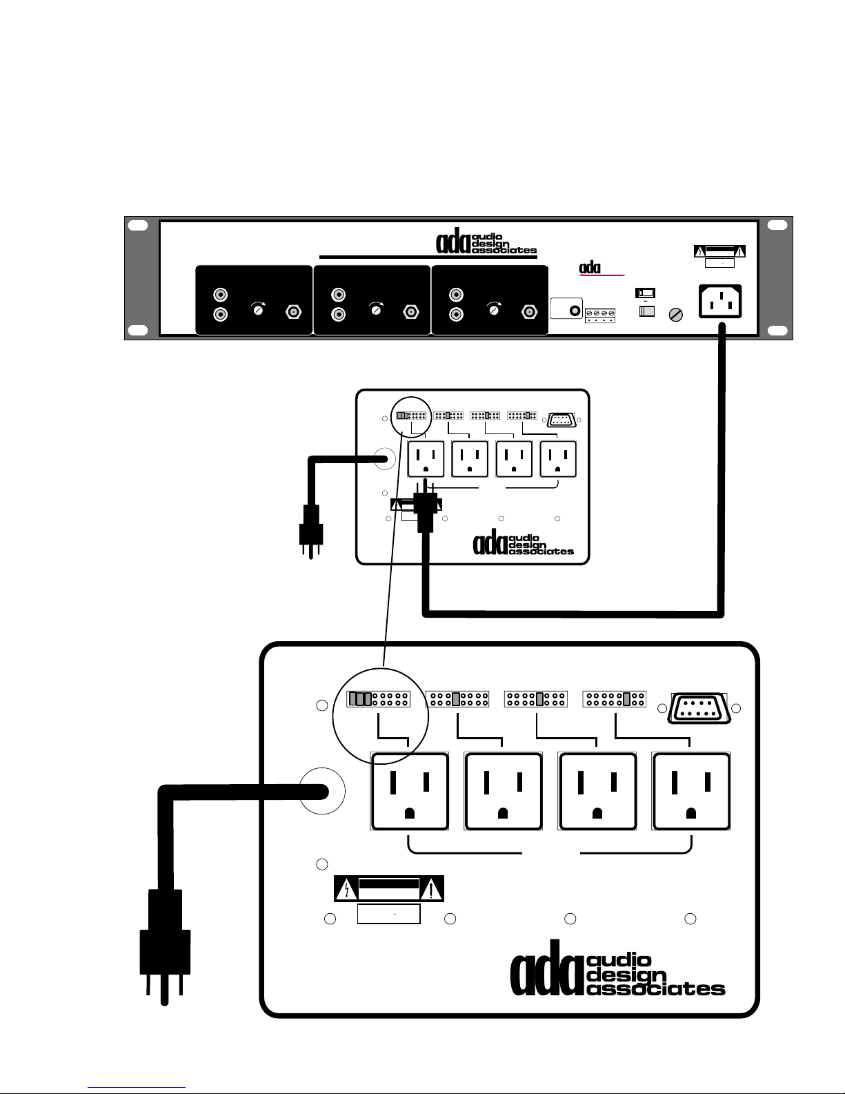
The ACC-48 features jumper pins (shunting pins) that determine which sources the outlet will
activate with. Several jumper pins can be inserted for any one outlet. In the case of the Trinity
Triple Tuner, the Trinity has only one AC cord, even though it acts like three components to
the system. As such, three jumper pins would be inserted into the Trinity Tuner’s ACC-48
outlet such that, whenever any of the three tuner modules is accessed, the tuner will get AC
and engage.
This device complies with Part 15 of the FCC Rules.
Operation is subject to the following two conditions:
1 This device may not cause harmful interference.
2 This device must accept any interference
received, including interference that may cause
undesired operation.
TUNER 1
AUDIO OUTPUT
L
R
OUTPUT
LEVEL
ANTENNA
TRINITY TRIPLE TUNER
TUNER 2
AUDIO OUTPUT
L
R
ANTENNA
OUTPUT
LEVEL
Set Shunting Pins To Engage AC With Zone Or Source Numbers 1-8
120-240 VAC
50-60 Hz
CAUTION
RISK OF ELECTRIC SHOCK
DO NOT OPEN
ATTENTION!
RISQUE DE CHOC ELECTRIQUE.
NE PAS OUVRIR
MADE IN U.S.A.
ACC-48
QUAD AC CONTROLLER
TUNER 3
AUDIO OUTPUT
L
R
OUTPUT
LEVEL
ANTENNA
12345678
3421
1000 WATTS
MAX TOTAL
1. Delta-88 9 Pin "D" programmed for source AC control. - Set one shunting
pin per AC outlet according to source inputs. Set 3 pins for MT-3000.
2. Delta-88 9 Pin "D" programmed for zone AC control. - Set one shunting
pen per AC outlet according to zone numbers. Set all shunting pins on
one AC Outlet for All-On source AC control when not using an ACC-3000.
IR Flasher
Input
TO 9 PIN "D"
DELTA-88123456781234567812345678
BUS
• ICC - I
NTERACTIVE COMPONENT COMMUNICATION
The Trinity Does Not
Require a BI-3000.
ADA Bus™
1 2 3 4
®
•
115V 230V
Voltage Selector
115 V
115V 2/10A S.B.
230V 1/10 AS.B.
115 V
CAUTION: DISCONNECT SUPPLY
CORD BEFORE SERVICING.
ATTENTION: DEBRANCHER AVANT
LE DEPANNAGE.
CAUTION
RISK OF ELECTRIC SHOCK
DO NOT OPEN
ATTENTION!
RISQUE DE CHOC ELECTRIQUE.
NE PAS OUVRIR
MADE IN U.S.A.
AC INPUT
Set Shunting Pins To Engage AC With Zone Or Source Numbers 1-8
120-240 VAC
50-60 Hz
CAUTION
RISK OF ELECTRIC SHOCK
DO NOT OPEN
ATTENTION!
RISQUE DE CHOC ELECTRIQUE.
NE PAS OUVRIR
MADE IN U.S.A.
ACC-48
QUAD AC CONTROLLER
12345678
TO 9 PIN "D"
DELTA-88123456781234567812345678
3421
1000 WATTS
1. Delta-88 9 Pin "D" programmed for source AC control. - Set one shunting
pin per AC outlet according to source inputs. Set 3 pins for MT-3000.
2. Delta-88 9 Pin "D" programmed for zone AC control. - Set one shunting
pen per AC outlet according to zone numbers. Set all shunting pins on
one AC Outlet for All-On source AC control when not using an ACC-3000.
- 7 -
MAX TOTAL
Page 9
Party Functions
d
d
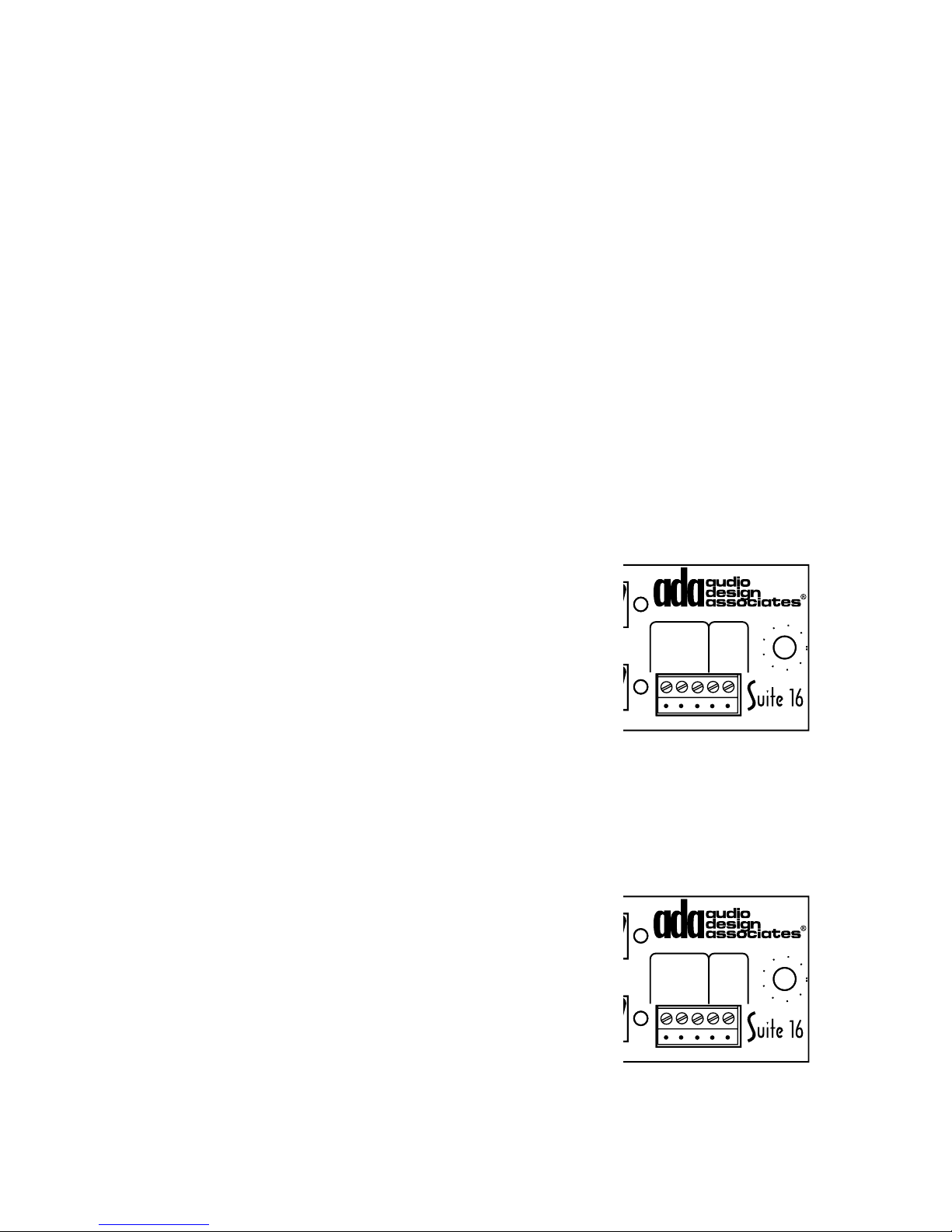
There are four “Party” functions which when activated, cause rooms to switch to the selected
source. As room outputs are programmed to track party groups, this feature is discussed
under P-16 features.
Paging Features
The A-16 also features a seventeenth input for paging. Unlike other systems, the Suite 16’s
paging feature is extensive. Included are three types of triggers (audio sensing, voltage
sensing, and serial controlled). Each trigger activates its own “paging group” of which there
are eight (six paging groups can be activated serially). Each paging group can be disabled
(from ever occurring) and any room can be a member of none, one, several or all paging
group(s). Serial control also permits room specific paging (for room-to-room paging). When
a paging trigger is activated, rooms that are directed to engage with that page load all current
settings into memory and then recall a paging volume preset, while setting tone controls to flat
and filters off. When the page is terminated, the previous settings are recalled. While each
paging feature needs to be turned off in order to return the room to normal operation, a user
can also clear a page while in progress by selecting another source in that room or by turning
the room off (This will remove the page for only that room. If other rooms are part of this
paging group, they will still page through.). Resetting power to the Suite 16, will also reset all
paging triggers to standby.
Paging Audio Input
This balanced audio input (600Ω) is accessed through the removable 5-pin screw terminal connector on the far right side of the A-16
Module. Here Pin 1 is common (shield), Pin 2 is Positive (+), and
Pin 3 is Negative (-). This input can be connected to the audio
A-16 • Audio Input Module
/16
/9
/10
Balanced
Audio Page
Input (600Ω)
1
Com
Tri gg er
5-24V
AC•DC
2
(+)3(-)4(+)5(-)
output of telephone systems or some other type of microphone mixing device.
Paging Compressor
ts
Paging Input/Trigger
The A-16 also features a paging compressor that limits the level of the audio paging signal
regardless of the actual input level. There is a trim pot to adjust the compressor, which is
located behind the AVP-16’s removable front panel plexi-glass plate.
Paging Volume Preset
Each room has a paging volume preset that is set in software. This volume level is independent of the volume level of the music playing in the room.
Paging Triggers
The A-16 features two non-serial controlled paging triggers. The
first is based on audio sensing through the balanced audio input
A-16 • Audio Input Module
/16
/9
/10
Balanced
Audio Page
Input (600Ω)
1
Com
Tri gg er
5-24V
AC•DC
2
(+)3(-)4(+)5(-)
previously described. There is a trim pot to adjust sensitivity of the
audio sensing trigger, which is located behind the AVP-16’s remov-
ts
able front panel plexi-glass plate. When engaged, the audio sens-
Paging Input/Trigger
ing trigger engages a group of rooms. The rooms that are activated with the audio sensing
trigger are predetermined in software by the installer. The audio sensing trigger can be defeated in software so that it never triggers the paging function. The audio sensing trigger,
once activated, must be deactivated in order to return the rooms to their prior state.
- 8 -
Page 10
The second trigger is a low voltage input trigger (3-24V AC or DC). It connects to the A-16 on
the removable 5-pin screw terminal connector on the far right side of the A-16 Module (Pin 4
is [+] and Pin 5 is [-], polarity does not matter for an AC trigger). The low voltage trigger, once
activated, must be deactivated in order to return the rooms to their prior state.
The A-16 Paging trigger can also be controlled serially. Here the paging functions are much
more robust. There are a total of six paging room groups. Rooms can be programmed by the
installer in software to either be part of one or several groups. Rooms can also be excluded
from all pages. Also, individual rooms can be selected to receive a page. This will permit
room specific paging. Again, once a serial trigger is engaged, it must be deactivated in order
for the room to return to its prior state.
P-16 Preamplifier Module
The P-16 Preamplifier Module is the most advanced stereo preamplifier for multi-room use.
With special attention placed on the sound quality of the Suite 16 System, the P-16 has a host
of features that are ideal for custom installation. The first AVP-16 can house one or two P16’s for up to 32 zones. Additional P-16s can be installed into additional AVP-16s for up to 96
zones (six P-16 Modules).
Zones 1- 6 & 7-12
1
23 45 67 8910111213141516
L
R
P-16
Zones 1-6
Zones 7-12
TO PTM-1225/1260
In 6/12
In 5/11
In 4/10
In 3/9
+12VDC Outputs
P-16 • Preamplifier Module
Zones 13-16
Gnd
+12VDC Output
In 1/7
Gnd
In 2/8
(-)13(+)14(+)15(+)16(+)
Audio Outputs
The P-16 houses sixteen stereo RCA audio outputs. Each audio output operates as its own
zone with independent: source selection; on, off, and muting; volume, bass and treble control;
maximum volume level; balance control; and even loudness and stereo enhancement filters.
The P-16 can be set so that zones down-mix to mono. Zones can also be set to provide either
a variable (signal to amplifiers) or fixed (signal to home theater preamplifiers or recording
devices) level audio output.
Input Selection
Each zone of the P-16 can directly access any one of the sixteen audio inputs independently
of each other. A zone turns on with an input selection. There are a total of eighteen serial
commands for a zones input selection, sixteen for the direct access of sources, and two more
commands for input up and input down selection.
Volume and Tone Controls
Each zone of the P-16 features independent volume, bass, and treble control. Serially, each
of these features has three commands, up, down and direct. As expected, the up and down
functions will raise or lower these parameters. The direct function is a numeric command that
immediately engages that specific level. This feature is ideal when creating sliders on touch
screen controls.
- 9 -
Page 11

Volume and Tone Presets
Each zone has four volume and four tone presets. Each of these eight presets has a serial
command to store the settings and another to recall these settings. The tone presets recall
and store both a bass and treble level as well as Loudness and Stereo Enhancement filter
settings. ADA suggests recalling both a Volume and Tone Preset when a room is turned on to
ensure that acoustic levels are appropriate.
Maximum Zone Volume Level
To prevent speaker damage, the installer can set in software, a zones maximum volume level
such that the user can never exceed this volume level.
Paging Volume Level
Because audio being paged has different characteristics than music, special concern needs
to be placed on the level of the audio signal during a page. If for example, music is playing
loud in a zone, should a page be introduced at the same volume level, one might expect to
speaker damage. To prevent this from occurring, each zone of the P-16 features a paging
volume preset level. During a page, the zone will set all tone controls flat, turn off all filters,
and recall the paging volume preset. Once the page is terminated, the previous settings are
recalled if that zone was previously on.
Balance Control
In some zones, it will be necessary to alter the balance of the audio levels between speakers.
To facilitate in this matter, the P-16 features a powerful balance control section. There are
three serial commands that control a room’s balance level: balance left, balance right, and
balance equal. Balance equal will instantly center the audio between the two speakers. There
are also two balance presets with four serial commands: balance preset 1 recall and store,
and balance preset 2 recall and store. If a room’s balance needs to be altered from the equal
position, ADA suggests storing the appropriate balance level in one of the two presets and
recalling it on start up.
Zone Turn-On Preset
Each zone of the P-16 can be set to either turn on to its last used state or presets 1. When
engaging with preset 1, Volume Preset 1, Tone Preset 1, and Balance Preset 1 are all recalled
as the zone turns on. This provides the installer with the ability to load into memory, ideal
acoustic characteristics when a room is first turned on. This will prevent a room from coming
on with inappropriate volume, bass, treble, or balance settings, even if these settings where
used the last time the room was on.
Party Zone Groups
There are four party zone groups which are set, cleared, and engaged serially. This feature
permits rooms to track the same source component and can be used to engage several
zones to the same source during a party. The feature can also be used for rooms that are
open to each other. In this application, it may be inappropriate to have one source component
playing in one room, while another is playing in an adjacent area because of interference. As
such, these rooms can have their control source selection buttons transmit one of the four
party commands. All rooms set to track that specific party function will turn to the same
source. For example, an entry foyer, living room, and dining room are open and adjacent to
each other. Each room has its own control. While it is desired that each area maintain
independent volume, tone, balance control, etc., it is not ideal that each area be capable of
- 10 -
Page 12

playing different sources at the same time. As such, the installer can program the controls in
these rooms to send party input commands instead of the standard input commands. As
such, whenever someone selects CD in the living room, the dining room and entry foyer will
turn on to CD as well. There are no restrictions as to which rooms track which of the four party
presets or whether they do not track any. Rooms can track several party presets as well.
Rooms do not have to have a control to engage with a party function from another room.
Mute and Room Off/All Off
Each zone features three serial mute commands: mute on, mute off, and mute toggle. There
are also two additional commands involving audio, room off and all off.
Stereo Enhancement and Loudness Contour Filters.
Each zone provides the option to engage/disengage two filters. These filters are used when
either speaker size, placement, or room acoustics are less than perfect. The Stereo Enhancement filter opens the sound stage between two speakers. If speakers are extremely
close together or in a position that is less than ideal, this filter may be of use. The Loudness
Contour Filter is used to enhance the bass output of speakers. If speakers have small bass
drivers or are in a position that baffles most of the bass information, this filter may be of use.
Both filter settings are encompassed in the Tone Presets.
Stereo & Mono
Here the P-16 is uniquely outfitted with both software and hardware options. Serially, one of
three preamplifier mixing options exist: stereo, mono input left, and mono input right. Stereo
(normally used), passes right and left channel audio inputs to the preamplifier stage. Mono
input left or right, pass only that channels information to the preamplifier stage. This feature
is useful if stereo recordings contain two completely different channels of information whereby
it is desired to eliminate one channel completely (language recordings).
While the software features may be of little use, the hardware mono/stereo feature is extremely important. While most rooms will most likely be set (hardware) for stereo (the P-16s
default state), it may be desirable for some zones to output a mono signal. Examples of such
areas may include hallways, galleries, outdoor areas, or even rooms that might contain only
one speaker (sauna). To down-mix to mono, the installer must alter a jumper-pin located on
the P-16 Module. This will require powering down the AVP-16, removing the P-16 Module,
locating the appropriate jumper (shunting pin) on the P-16 circuit board and inserting the
jumper. At this time, that zones audio output will be same on both right and left channels,
regardless of the separation of the input signal.
Variable and Fixed Outputs
The P-16 also permits any zone to have its output at either a fixed audio level (unprocessed)
or variable level (all previously mentioned preamplifier features). This is extremely useful
when desiring to include home theater systems or recording devices onto a Suite 16. Normally, the P-16s are inserted into an AVP-16 where zones 1-12 are set to variable (for multiroom audio) and zones 13-16 are set to fixed (the line-level audio signal can be routed to the
input of a high-end home theater preamplifier, A/V receiver, high-end two channel preamplifier, TV audio input, or recording device). To alter any zone, you must locate that zones
appropriate jumper pins (shunting pins) which are located on the P-16 Module circuit board
and move them to the alternate setting. There are two jumper pins per zone (for left and right
channels). This will require powering down the AVP-16 and removing the P-16 Module.
- 11 -
Page 13
Low Voltage Triggers
1
Z
1
n
)
o
d
1
The P-16 features three low voltage trigger outputs: two 9-pin “D”
type connectors (these are not RS-232) and one removable five-pin
screw terminal connector. The top 9-pin “D” connector provides a
single ground pin and six pins that go to +12VDC individually with
respect to zones 1-6. Likewise, the bottom 9-pin “D” connector provides a single ground pin and six pins that to go +12VDC for zones 7-
12. These zone triggers can connect directly to the PTM-1225 or
PTM-1260 Twelve Channel Power Amplifiers. These amplifiers utilize the zone triggers to mute and unmute zones as they are engaged by the P-16. A standard straight-through 9-Pin “D” male-tomale cable can be used (both PTM-1225 and PTM-1260 Power
Amplifiers come with this cable).
Zones 1- 6 & 7-12
nes 1-6
TO PTM-1225/1260
In 6/12
In 5/11
In 4/10
In 3/9
es 7-12
+12VDC Outputs
12
Gnd
In 1/7
In 2/8
P-
+
G
(-
The removable 5-pin screw terminal connector is used to provide a
low voltage trigger for zones 13-16. Here, pin 1 is ground (-), pin 2
engages (+12VDC) with zone 13, pin 3 engages with zone 14,. pin 4
engages with zone 15, and pin 5 engages with zone 16. ADA provides the ACC-3 Low Voltage Triggered AC Controller which can be
used to turn on any size ADA power amplifier.
Power Amplifier Options
Two ADA power amplifiers
offer easy connections directly to the P-16 Module.
The PTM-1225 will provide
medium power to up to six
zones (25W/Ch @ 8Ω, 45W/
Ch @ 4Ω, stable to 2Ω).
The PTM-1260 will provide
high power to up to six zones
(Unbridged - 85W/Ch @ 8Ω,
135W/Ch @ 4Ω, stable to
2Ω). You can opt to use two
PTM-1225s, one PTM-1225
and one PTM-1260, or two
PTM-1260s.
Bypass
Trigger
480 WATTS MAX
115V~/60Hz
230V~/50Hz
All Zones
12VDC
1(-) 2(+)
4 ASB - 115V~
2 ASB - 230V~
Individual
Zones
PTM-1260
VOLTAGE
SELECTOR
CAUTION
RISK OF ELECTRIC SHOCK
DO NOT OPEN
115 V
ATTENTION!
RISQUE DE CHOC ELECTRIQUE.
NE PAS OUVRIR
MADE IN U.S.A.
ZONE 1
16-2Ω
+ R - - L +
10KΩ 10KΩ 10KΩ 10KΩ 10KΩ 10KΩ
WARNING! Risk Of Hazardous Energy!
Make Proper Connections.
AVERTISSEMENT! Energie Electrique Dangereuse! Faire Des
Connexions Propres Pour L'Hautparleur.
Voir La Notice De Fonctionnement.
CAUTION: Disconnect Supply Cord Before Servicing.
ATTENTION: Debrancher Avant Le Depannage.
ZONE 2
L
16-2Ω
+ R - - L +
R
ZONE 3
L
16-2Ω
+ R - - L +
R
DO NOT SHORT OUTPUTS!
L
R
ZONE 4
16-2Ω
+ R - - L +
P-16 • Preamplifier M
Zones 13-16
260
+12VDC Output
/7
Gnd
/8
(-)13(+)14(+)15(+)16(+)
ts
PTM-1225
12 Channel Power Amp
ZONE 5
L
16-2Ω
+ R - - L +
R
ZONE 6
L
16-2Ω
+ R - - L +
R
L
R
The PTM-1260 can also be
set so that channel pairs are
bridged, from 12 to 10, 8, or
6 channels. In bridged mode
power increases to 350W/Ch
into 4Ω. In bridged mode, the
PTM-1260 is stable to 4Ω.
ZONE 1
LEFT/ 1
L
-
COM COM
BRIDGED
BRIDGED/ 4
-
-
R
IGHT/ 7LEFT/ 8
ZONE 4
WARNING! RISK OF HAZARDOUS
ENERGY! MAKE PROPER SPEAKER
CONNECTIONS.
+
+
+
+
STEREO
R
COM COM
+
RIGHT/ 2
-
-
BRIDGED/ 1
-
- 12 -
PTM-1260 POWER AMP
ZONE 2
LEFT/ 3
L
-
+
STEREO
R
COM COM
BRIDGED
BRIDGED/ 5
BRIDGED
R
STEREO
L
+
-
COM COM
+
+
-
R
IGHT/ 9LEFT/ 10
ZONE 5
AVERTISSEMENT! ENERGIE ELECTRIQUE DANGEREUSE!
FAIRE DES CONNEXIONS PROPRES POUR
L'HAUTPARLEUR. VOIR LA NOTICE DE FONCTIONNEMENT.
+
+
BRIDGED/ 2
RIGHT/ 4
L
-
+
STEREO
R
-
BRIDGED
BRIDGED
COM COM
R
STEREO
+
-
L
RIGHT/ 11
CAUTION: DISCONNECT SUPPLY CORD BEFORE SERVICING.
ATTENTION: DEBRANCHER AV LE DEPANNAGE.
ZONE 3
LEFT/ 5
-
+
COM COM
+
BRIDGED/ 3
BRIDGED/ 6
+
-
+
-
-
L
EFT/ 12
ZONE 6
RIGHT/ 6
-
-
BRIDGED
STEREO
+
STANDBY
REPLACE WITH SAME VALUE FUSE
2/10A S.B.~115V
1/10A S.B.~230V
CAUTION
RISK OF ELECTRIC SHOCK
DO NOT OPEN
R
ATTENTION!
RISQUE DE CHOC ELECTRIQUE.
NE PAS OUVRIR
MADE IN U.S.A.
L
VOLTAGE SWITCH
115 V~ / 230 V~
9-P
ALL ZONES
IN D CONNECTOR
DC TRIGGER
OPERATES DELTA-88
1 2
ONE TRIGGERS
Z
1-6 ONLY
(-) (+)
TRIGGER
115 V
SWITCH
VOLTAGE
SWITCH
EXTERNAL DC TRIGGERS
BYPASS
115 V~ /
230 V~
POWER
115 V~ / 230 V~
50 Hz / 60 Hz
MAIN
REPLACE
WITH SAME
VALUE FUSE
115 V
10A S.B.~115V
5A S.B.~230V
1500W
Page 14
Zones 1- 6 & 7-12
Zones 1-6
Zones 7-12
PTM-1225
12 Channel Power Amp
ZONE 5
L
16-2Ω
+ R - - L +
R
PTM-1225
12 Channel Power Amp
ZONE 5
L
16-2Ω
+ R - - L +
R
TO PTM-1225/1260
In 6/12
In 5/11
In 4/10
In 3/9
+12VDC Outputs
P-16 • Preamplifier Module
Zones 13-16
Gnd
+12VDC Output
In 1/7
Gnd
In 2/8
(-)13(+)14(+)15(+)16(+)
L
R
L
R
ZONE 6
16-2Ω
+ R - - L +
ZONE 6
16-2Ω
+ R - - L +
L
R
L
R
Bypass
Trigger
Bypass
Trigger
480 WATTS MAX
115V~/60Hz
230V~/50Hz
All Zones
12VDC
1(-) 2(+)
480 WATTS MAX
115V~/60Hz
230V~/50Hz
All Zones
12VDC
1(-) 2(+)
1
2 3 4 5 6 7 8 9 10 11 12 13 14 15 16
L
R
CAUTION
RISK OF ELECTRIC SHOCK
DO NOT OPEN
115 V
ATTENTION!
115 V
ZONE 1
16-2Ω
+ R - - L +
ZONE 1
16-2Ω
+ R - - L +
RISQUE DE CHOC ELECTRIQUE.
NE PAS OUVRIR
MADE IN U.S.A.
CAUTION
RISK OF ELECTRIC SHOCK
DO NOT OPEN
ATTENTION!
RISQUE DE CHOC ELECTRIQUE.
NE PAS OUVRIR
MADE IN U.S.A.
4 ASB - 115V~
2 ASB - 230V~
Individual
Zones
4 ASB - 115V~
2 ASB - 230V~
Individual
Zones
VOLTAGE
SELECTOR
VOLTAGE
SELECTOR
P-16
WARNING! Risk Of Hazardous Energy!
Make Proper Connections.
AVERTISSEMENT! Energie Electrique Dangereuse! Faire Des
Connexions Propres Pour L'Hautparleur.
Voir La Notice De Fonctionnement.
CAUTION: Disconnect Supply Cord Before Servicing.
ATTENTION: Debrancher Avant Le Depannage.
ZONE 2
L
16-2Ω
+ R - - L +
R
10KΩ 10KΩ 10KΩ 10KΩ 10KΩ 10KΩ
WARNING! Risk Of Hazardous Energy!
AVERTISSEMENT! Energie Electrique Dangereuse! Faire Des
Connexions Propres Pour L'Hautparleur.
CAUTION: Disconnect Supply Cord Before Servicing.
ATTENTION: Debrancher Avant Le Depannage.
ZONE 2
L
16-2Ω
+ R - - L +
R
10KΩ 10KΩ 10KΩ 10KΩ 10KΩ 10KΩ
DO NOT SHORT OUTPUTS!
ZONE 3
L
16-2Ω
+ R - - L +
R
Make Proper Connections.
Voir La Notice De Fonctionnement.
DO NOT SHORT OUTPUTS!
ZONE 3
L
16-2Ω
+ R - - L +
R
L
R
L
R
ZONE 4
16-2Ω
+ R - - L +
ZONE 4
16-2Ω
+ R - - L +
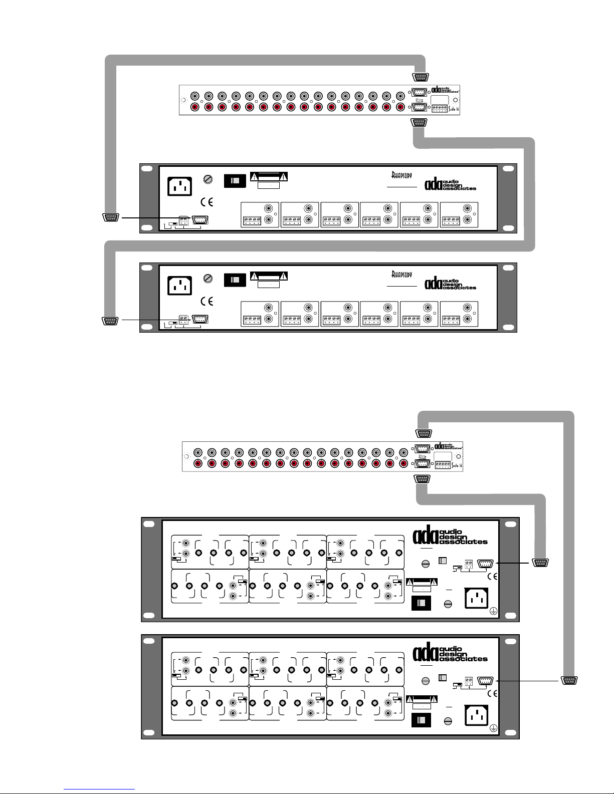
Both the PTM-1225 and PTM-1260 feature the six zone low voltage trigger, that mutes zones
when they are not in use. Connection of this trigger is easy with the provided 9-pin D style
ribbon cables. You can opt to use two PTM-1225s for medium power or two PTM-1260s for
high power. You can also use one of each as shown on the next page.
1
2 3 4 5 6 7 8 9 10 11 12 13 14 15 16
L
R
Z
ONE
1
L
EFT
L
S
TEREO
R
B
COM COM
+
R
L
S
TEREO
R
B
COM COM
+
R
/ 1
-
COM COM
RIDGED
B
RIDGED
/ 4
+
-
+
-
IGHT
/ 7L
Z
ONE
WARNING! RISK OF HAZARDOUS
ENERGY! MAKE PROPER SPEAKER
CONNECTIONS.
Z
ONE
L
EFT
/ 1
-
COM COM
RIDGED
B
RIDGED
/ 4
+
-
+
-
IGHT
/ 7L
Z
ONE
WARNING! RISK OF HAZARDOUS
ENERGY! MAKE PROPER SPEAKER
CONNECTIONS.
+
+
B
EFT
/ 8
4
1
+
+
B
EFT
/ 8
4
RIDGED
RIDGED
R
IGHT
-
-
/ 1
-
R
IGHT
-
-
/ 1
-
PTM-1260 P
/ 2
L
+
S
TEREO
R
B
RIDGED
B
RIDGED
COM COM
R
S
TEREO
+
L
IGHT
/ 9L
R
AVERTISSEMENT! ENERGIE ELECTRIQUE DANGEREUSE!
L'HAUTPARLEUR. VOIR LA NOTICE DE FONCTIONNEMENT.
PTM-1260 P
/ 2
L
+
S
TEREO
R
B
RIDGED
B
RIDGED
COM COM
R
S
TEREO
+
L
IGHT
/ 9L
R
AVERTISSEMENT! ENERGIE ELECTRIQUE DANGEREUSE!
L'HAUTPARLEUR. VOIR LA NOTICE DE FONCTIONNEMENT.
P-16
OWER AMP
Z
ONE
2
L
EFT
/ 3
-
+
COM COM
+
B
RIDGED
B
RIDGED
-
-
FAIRE DES CONNEXIONS PROPRES POUR
B
RIDGED
-
-
FAIRE DES CONNEXIONS PROPRES POUR
/ 2
/ 5
+
+
-
EFT
/ 10
Z
ONE
5
OWER AMP
Z
ONE
2
L
EFT
/ 3
-
+
COM COM
+
B
RIDGED
/ 2
/ 5
+
+
-
EFT
/ 10
Z
ONE
5
R
IGHT
/ 4
L
-
+
S
TEREO
R
-
B
RIDGED
B
B
RIDGED
S
TEREO
R
IGHT
/ 4
-
-
B
RIDGED
S
TEREO
RIDGED
-
COM COM
R
+
-
L
R
IGHT
/ 11
CAUTION: DISCONNECT SUPPLY CORD BEFORE SERVICING.
ATTENTION: DEBRANCHER AV LE DEPANNAGE.
L
+
S
TEREO
R
B
RIDGED
B
RIDGED
-
COM COM
R
+
-
L
R
IGHT
/ 11
CAUTION: DISCONNECT SUPPLY CORD BEFORE SERVICING.
ATTENTION: DEBRANCHER AV LE DEPANNAGE.
Z
ONE
3
L
EFT
/ 5
R
-
COM COM
/ 6
L
-
COM COM
/ 6
IGHT
-
+
-
+
B
RIDGED
/ 3
B
RIDGED
+
+
L
Z
ONE
Z
ONE
EFT
/ 5
+
+
L
Z
ONE
S
-
EFT
/ 12
6
3
R
IGHT
+
-
-
+
B
RIDGED
/ 3
B
RIDGED
S
-
EFT
/ 12
6
Zones 1- 6 & 7-12
Zones 1-6
TO PTM-1225/1260
In 6/12
In 5/11
In 4/10
In 3/9
Zones 7-12
+12VDC Outputs
/ 6
+
REPLACE WITH SAME VALUE FUSE
2/10A S.B.~115V
1/10A S.B.~230V
CAUTION
RISK OF ELECTRIC SHOCK
DO NOT OPEN
R
ATTENTION!
RISQUE DE CHOC ELECTRIQUE.
TEREO
NE PAS OUVRIR
MADE IN U.S.A.
L
VOLTAGE SWITCH
115 V~ / 230 V~
/ 6
+
REPLACE WITH SAME VALUE FUSE
2/10A S.B.~115V
1/10A S.B.~230V
CAUTION
RISK OF ELECTRIC SHOCK
DO NOT OPEN
R
ATTENTION!
RISQUE DE CHOC ELECTRIQUE.
TEREO
NE PAS OUVRIR
MADE IN U.S.A.
L
VOLTAGE SWITCH
115 V~ / 230 V~
STANDBY
115 V
STANDBY
115 V
Gnd
In 1/7
In 2/8
P-16 • Preamplifier Module
Zones 13-16
+12VDC Output
Gnd
(-)13(+)14(+)15(+)16(+)
115 V
VOLTAGE
SWITCH
B
YPASS
115 V~ /
230 V~
MAIN
REPLACE
WITH SAME
VALUE FUSE
10A S.B.~115V
5A S.B.~230V
115 V
VOLTAGE
SWITCH
B
YPASS
115 V~ /
230 V~
MAIN
REPLACE
WITH SAME
VALUE FUSE
10A S.B.~115V
5A S.B.~230V
9-P
ALL Z
ONES
IN
D C
ONNECTOR
DC T
RIGGER
O
PERATES DELTA
-88
1 2
ONE TRIGGERS
Z
(-) (+)
1-6 O
E
XTERNAL
ALL Z
DC T
1 2
(-) (+)
E
XTERNAL
DC T
RIGGERS
POWER
115 V~ / 230 V~
50 Hz / 60 Hz
1500W
9-P
ONES
RIGGER
O
DC T
RIGGERS
POWER
115 V~ / 230 V~
50 Hz / 60 Hz
1500W
IN
D C
PERATES DELTA
Z
ONE TRIGGERS
1-6 O
ONNECTOR
NLY
-88
NLY
T
RIGGER
S
WITCH
T
RIGGER
S
WITCH
- 13 -
Page 15
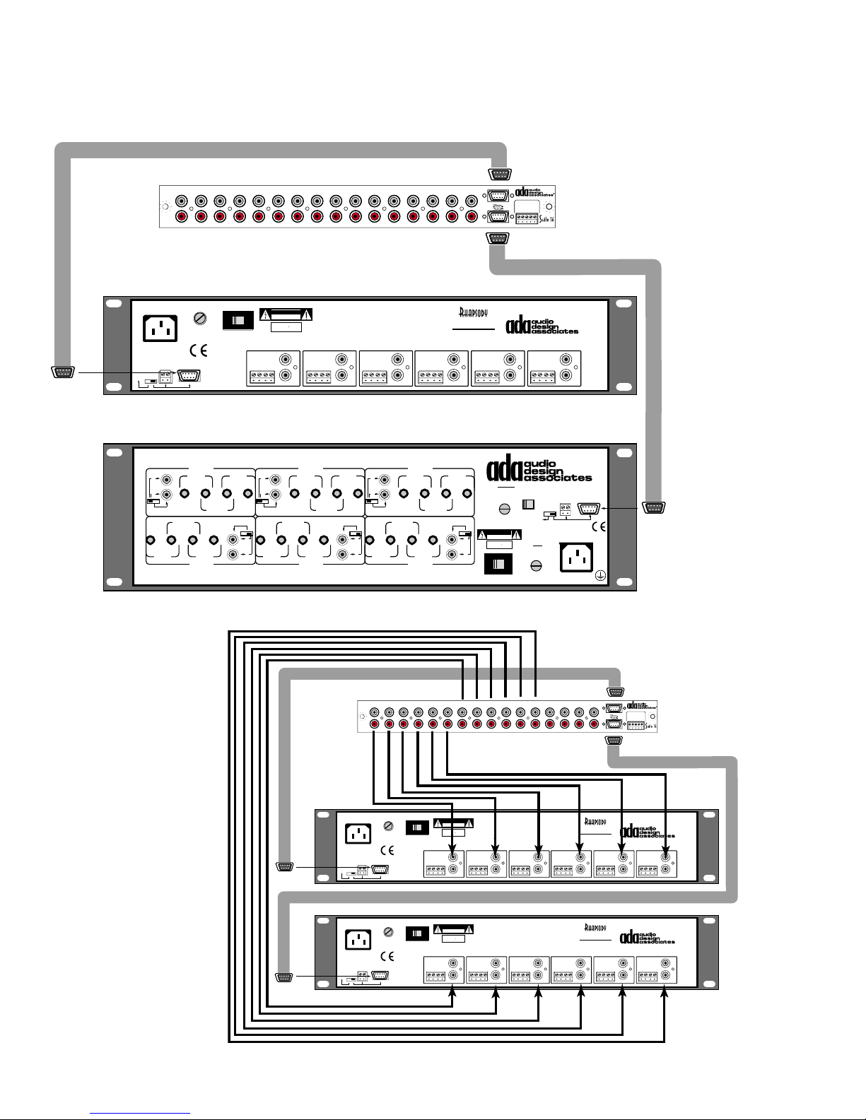
The diagram below shows that zones 1-6 are running on medium power using a PTM-1225,
while zones 7-12 are running on high power using the PTM-1260 (as a six zone/twelve channel amplifier - unbridged). When duplicating this scenario, it does not matter whether the
PTM-1260 is running
zones 1-6 or 7-12.
Zones 1- 6 & 7-12
Zones 1-6
Zones 7-12
PTM-1225
12 Channel Power Amp
ZONE 5
L
16-2
+ R - - L +
R
TO PTM-1225/1260
In 6/12
In 5/11
In 4/10
In 3/9
+12VDC Outputs
P-16 • Preamplifier Module
Zones 13-16
Gnd
+12VDC Output
In 1/7
Gnd
In 2/8
(-)13(+)14(+)15(+)16(+)
L
R
ZONE 6
16-2
+ R - - L +
L
R
Bypass
Trigge r
480 WATTS MAX
115V~/60Hz
230V~/50Hz
All Zones
12VDC
1(-) 2(+)
1
2 3 4 5 6 7 8 9 10 11 12 13 14 15 16
L
R
CAUTION
RISK OF ELECTRIC SHOCK
DO NOT OPEN
115 V
ATTENTION!
VOLTAGE
ZONE 1
16-2
+ R - - L +
RISQUE DE CHOC ELECTRIQUE.
NE PAS OUVRIR
MADE IN U.S.A.
4 ASB - 115V~
2 ASB - 230V~
Individual
Zones
SELECTOR
P-16
WARNING! Risk Of Hazardous Energy!
Make Proper Connections.
AVERTISSEMENT! Energie Electrique Dangereuse! Faire Des
Connexions Propres Pour L'Hautparleur.
Voir La Notice De Fonctionnement.
CAUTION: Disconnect Supply Cord Before Servicing.
ATTENTION: Debrancher Avant Le Depannage.
ZONE 2
L
16-2
+ R - - L +
R
10K 10K 10K 10K 10K 10K
ZONE 3
L
+ R - - L +
R
DO NOT SHORT OUTPUTS!
16-2
ZONE 4
L
16-2
+ R - - L +
R
Z
ONE
L
EFT
L
S
TEREO
R
B
COM COM
+
R
/ 1
-
COM COM
RIDGED
B
RIDGED
/ 4
+
-
+
-
IGHT
/ 7L
Z
ONE
WARNING! RISK OF HAZARDOUS
ENERGY! MAKE PROPER SPEAKER
CONNECTIONS.
Whether you are using the PTM-1225 or
the PTM-1260 power
amplifiers, you will
need to connect the
stereo line-level RCA
audio cables between
the P-16 Module and
the amplifier inputs.
These cables are in
addition to the ribbon
cables that trigger the
amplifier zones.
R
IGHT
-
-
/ 1
-
PTM-1260 P
/ 2
L
+
S
TEREO
R
B
RIDGED
B
RIDGED
COM COM
R
S
TEREO
+
L
IGHT
/ 9L
R
AVERTISSEMENT! ENERGIE ELECTRIQUE DANGEREUSE!
L'HAUTPARLEUR. VOIR LA NOTICE DE FONCTIONNEMENT.
1
+
+
B
RIDGED
EFT
/ 8
4
OWER AMP
Z
ONE
2
L
EFT
/ 3
-
+
COM COM
+
B
RIDGED
B
RIDGED
-
-
FAIRE DES CONNEXIONS PROPRES POUR
/ 2
/ 5
+
+
-
EFT
/ 10
Z
ONE
5
R
IGHT
/ 4
L
-
+
S
TEREO
R
-
B
RIDGED
B
RIDGED
-
COM COM
R
+
-
L
R
IGHT
/ 11
CAUTION: DISCONNECT SUPPLY CORD BEFORE SERVICING.
ATTENTION: DEBRANCHER AV LE DEPANNAGE.
1
2 3 4 5 6 7 8 9 10 11 12 13 14 15 16
L
R
4 ASB - 115V~
2 ASB - 230V~
All Zones
Individual
12VDC
Zones
1(-) 2(+)
Bypass
Trigge r
B
RIDGED
S
TEREO
480 WATTS MAX
115V~/60Hz
230V~/50Hz
Z
ONE
3
L
EFT
/ 5
R
-
COM COM
/ 6
SELECTOR
IGHT
-
+
-
+
B
RIDGED
/ 3
B
RIDGED
+
S
-
EFT
/ 12
6
CAUTION
RISK OF ELECTRIC SHOCK
DO NOT OPEN
115 V
ATTENTION!
RISQUE DE CHOC ELECTRIQUE.
NE PAS OUVRIR
MADE IN U.S.A.
ZONE 1
L
16-2Ω
+ R - - L +
R
10KΩ 10KΩ 10KΩ 10KΩ 10KΩ 10KΩ
Z
VOLTAGE
+
L
ONE
/ 6
+
STANDBY
REPLACE WITH SAME VALUE FUSE
2/10A S.B.~115V
1/10A S.B.~230V
CAUTION
RISK OF ELECTRIC SHOCK
DO NOT OPEN
R
ATTENTION!
RISQUE DE CHOC ELECTRIQUE.
TEREO
NE PAS OUVRIR
MADE IN U.S.A.
L
115 V
VOLTAGE SWITCH
115 V~ / 230 V~
P-16
WARNING! Risk Of Hazardous Energy!
Make Proper Connections.
AVERTISSEMENT! Energie Electrique Dangereuse! Faire Des
Connexions Propres Pour L'Hautparleur.
Voir La Notice De Fonctionnement.
CAUTION: Disconnect Supply Cord Before Servicing.
ATTENTION: Debrancher Avant Le Depannage.
ZONE 2
+ R - - L +
ZONE 3
L
16-2Ω
16-2Ω
+ R - - L +
R
T
115 V
S
VOLTAGE
SWITCH
B
YPASS
115 V~ /
230 V~
MAIN
REPLACE
WITH SAME
VALUE FUSE
10A S.B.~115V
5A S.B.~230V
DO NOT SHORT OUTPUTS!
L
R
RIGGER
WITCH
ALL Z
DC T
E
XTERNAL
ZONE 4
16-2Ω
+ R - - L +
ONES
RIGGER
1 2
(-) (+)
DC T
115 V~ / 230 V~
50 Hz / 60 Hz
IN
D C
9-P
O
PERATES DELTA
Z
ONE TRIGGERS
1-6 O
RIGGERS
POWER
1500W
PTM-1225
12 Channel Power Amp
ONNECTOR
-88
NLY
Zones 1- 6 & 7-12
Zones 1-6
P-16 • Preamplifier Module
Zones 13-16
TO PTM-1225/1260
In 6/12
In 5/11
Gnd
+12VDC Output
In 4/10
In 1/7
Gnd
In 2/8
In 3/9
(-)13(+)14(+)15(+)16(+)
Zones 7-12
+12VDC Outputs
ZONE 5
L
+ R - - L +
R
ZONE 6
L
16-2Ω
R
16-2Ω
+ R - - L +
L
R
ADA suggests using
cables that are of appropriate length that
are non-directional.
Directional cable may
cause ADA amplifiers
to oscillate.
Bypass
Trigge r
480 WATTS MAX
115V~/60Hz
230V~/50Hz
All Zones
12VDC
1(-) 2(+)
4 ASB - 115V~
2 ASB - 230V~
Individual
Zones
- 14 -
WARNING! Risk Of Hazardous Energy!
CAUTION
RISK OF ELECTRIC SHOCK
DO NOT OPEN
115 V
ATTENTION!
RISQUE DE CHOC ELECTRIQUE.
NE PAS OUVRIR
VOLTAGE
MADE IN U.S.A.
SELECTOR
ZONE 1
16-2Ω
+ R - - L +
10KΩ 10KΩ 10KΩ 10KΩ 10KΩ 10KΩ
Make Proper Connections.
AVERTISSEMENT! Energie Electrique Dangereuse! Faire Des
Connexions Propres Pour L'Hautparleur.
Voir La Notice De Fonctionnement.
CAUTION: Disconnect Supply Cord Before Servicing.
ATTENTION: Debrancher Avant Le Depannage.
ZONE 2
L
+ R - - L +
R
ZONE 3
L
16-2Ω
+ R - - L +
R
DO NOT SHORT OUTPUTS!
16-2Ω
ZONE 4
L
16-2Ω
+ R - - L +
R
PTM-1225
12 Channel Power Amp
ZONE 5
L
+ R - - L +
R
ZONE 6
L
16-2Ω
R
16-2Ω
+ R - - L +
L
R
Page 16
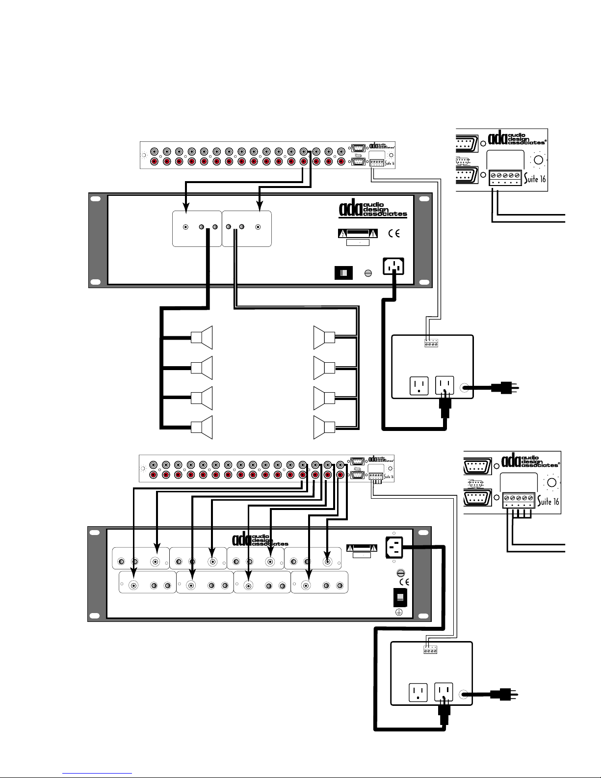
If zones require ultra-high power amplification, ADA suggests using PF-2501 Power Amplifi-
CAUTION
RISK OF ELECTRIC SHOCK
DO NOT OPEN
ATTENTION!
RISQUE DE CHOC ELECTRIQUE.
NE PAS OUVRIR
MADE IN U.S.A.
CAUTION
RISK OF ELECTRIC SHOCK
DO NOT OPEN
ATTENTION!
RISQUE DE CHOC ELECTRIQUE.
NE PAS OUVRIR
MADE IN U.S.A.
ers (250W/Ch @ 8Ω, 450W/Ch @ 4Ω, stable to 2Ω) along with an ACC-3 AC Controller. If
zones require driving a great many speakers (up to sixteen pairs @ 8Ω), ADA suggests using
a PF-201 (60W/Ch @ 8Ω, 240W/Ch @ 1/2Ω) along with an ACC-3 AC Controller. These
amplifiers are optimally running on zones 13-16 because of screw termination connectivity of
the ACC-3 to the P-16.
1
23 4567 8910111213141516
L
R
CAUTION! DO NOT SHORT OUTPUTS!
INPUT
47K
Ω
OUTPUT 1/2-16
WARNING!
RISK OF HAZARDOUS
ENERGY!
MAKE PROPER SPEAKER
CONNECTIONS.
LEFT
P-16
Ω
OUTPUT 1/2-16
Ω
+-
-+
CH BCH A
AVERTISSEMENT! ENERGIE
ELECTRIQUE DANGEREUSE! FAIRE
DES CONNEXIONS PROPRES POUR
L'HAUTPARLEUR. VOIR LA NOTICE
DE FONCTIONNEMENT.
INPUT
47K
Ω
CAUTION: DISCONNECT SUPPLY CORD
BEFORE SERVICING.
ATTENTION: DEBRANCHER AVANT
LE DEPANNAGE.
RIGHT
Zones 1-6
Zones 7-12
PF-201 P
VOLTAGE
SWITCH
115 V - 230 V
115 V
Zones 1- 6 & 7-12
TO PTM-1225/1260
In 6/12
In 5/11
In 4/10
In 3/9
+12VDC Outputs
P-16 • Preamplifier Module
Gnd
In 1/7
Gnd
In 2/8
REPLACE
WITH SAME
VALUE FUSE
10A S.B.
Zones 13-16
+12VDC Output
(-)13(+)14(+)15(+)16(+)
OWER AMP
POWER
115 V - 230 V
50 Hz - 60 Hz
1- 6 & 7-12
TO PTM-1225/1260
C Outputs
ACC-3
PIN 1 (-)
PIN 2 (+)
P-16 • Preamplifier Module
Zones 13-16
Gnd
+12VDC Output
In 1/7
Gnd
In 2/8
(-)13(+)14(+)15(+)16(+)
PARALLEL
ALL
SPEAKERS
OUTDOOR
AREA
1
23 4567 8910111213141516
L
R
PTM-8150
E
IGHT CHANNEL POWER AMPLIFIER
OUTPUT
Ω
CH
2-16
+-
1
INPUT
Ω
CH
47K
5
INPUT
47K
OUTPUT
2-16
+-
OUTPUT
2-16
Ω
INPUT
Ω
47K
INPUT
Ω
CH
+-
2
OUTPUT
Ω
CH
+-
6
P-16
OUTPUT
2-16
Ω
47K
INPUT
47K
Ω
2-16
INPUT
47K
OUTPUT
2-16
+-
OUTPUT
Ω
2-16
INPUT
Ω
47K
Ω
CH
+-
3
Ω
CH
7
INPUT
Ω
Ω
Ω
CH
47K
+-
4
OUTPUT
Ω
CH
2-16
+-
8
CAUTION! DO NOT SHORT OUTPUTS!
The PTM-8150 Eight Channel High Power Amplifier can be used to provide high power to zones 13-
16. Again use an ACC-3 to turn on the PTM-8150
when any of these four zones are turned on. On
the P-16, use a small jumper wire to terminate together pins 2-5 and use a common ground (-).
Zones 1- 6 & 7-12
Zones 1-6
P-16 • Preamplifier Module
Zones 13-16
TO PTM-1225/1260
In 6/12
Gnd
In 5/11
+12VDC Output
In 1/7
In 4/10
Gnd
In 2/8
In 3/9
(-)13(+)14(+)15(+)16(+)
Zones 7-12
+12VDC Outputs
1500W POWER
115 V~/60 Hz • 230 V~/50 Hz
CAUTION:
DISCONNECT SUPPLY
CORD BEFORE
SERVICING.
ATTENTION:
DEBRANCHER AVANT
LE DEPANNAGE.
WARNING!
RISK OF HAZARDOUS
ENERGY!
MAKE PROPER SPEAKER
CONNECTIONS.
AVERTISSEMENT! ENERGIE
ELECTRIQUE DANGEREUSE! FAIRE
DES CONNEXIONS PROPRES POUR
L'HAUTPARLEUR. VOIR LA NOTICE
DE FONCTIONNEMENT.
REPLACE
WITH SAME
VALUE FUSE
10A S.B.~115V
5A S.B.~230V
VOLTAGE
SWITCH
230 V~
115 V~
1234
-A+ -B+
ACC-3
es 1- 6 & 7-12
P-16 • Preamplifier Module
Gnd
In 1/7
In 2/8
Zones 13-16
+12VDC Output
Gnd
(-)13(+)14(+)15(+)16(+)
TO PTM-1225/1260
2
1
0
/9
VDC Outputs
115 V
ACC-3
PIN 1 (-)
PIN 2 (+)
1234
-A+ -B+
ACC-3
- 15 -
Page 17
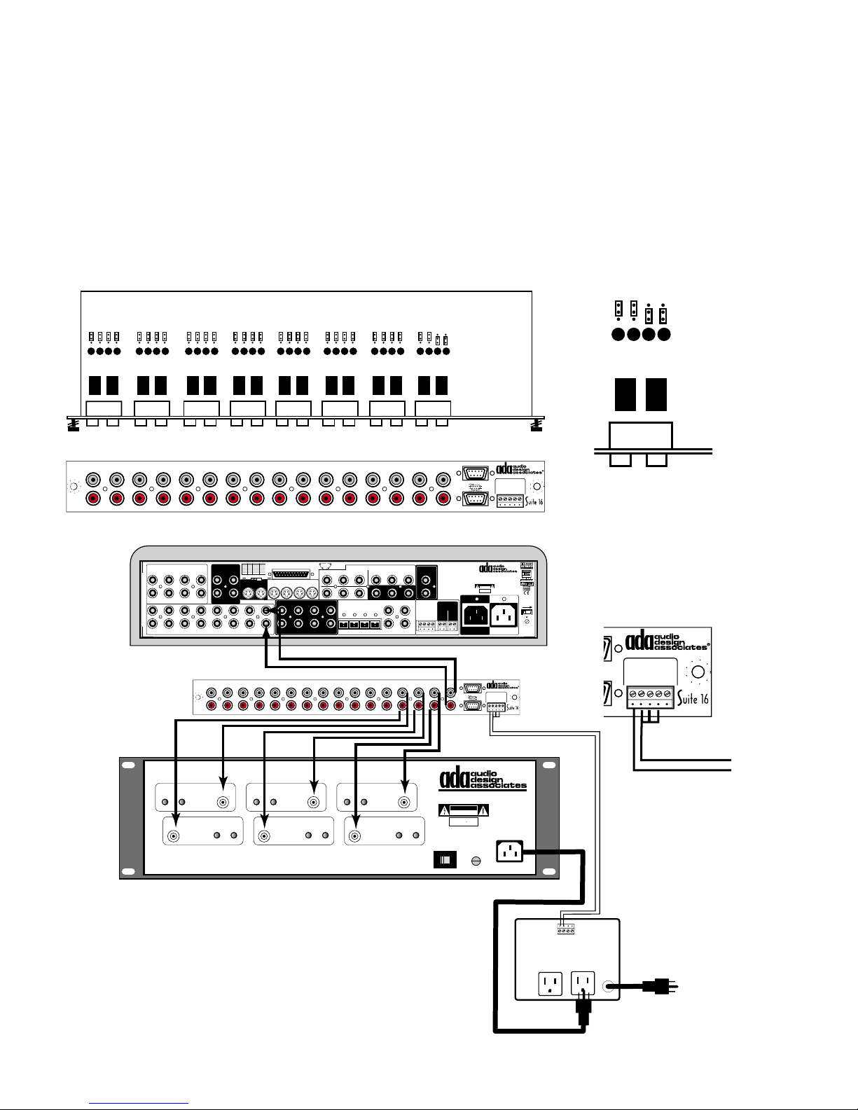
Home Theater (or Recording) Set Up
When working with home theater preamplifiers, whether they are in the form of an AV receiver
or separate preamplifier and amplifier, you can assign a Suite 16 zone output to the theater
room. As such, the theater preamplifier can play the same components that are playing
through the rest of the home. To do this, connect a zone’s line-level audio signal to your
home theater preamp or receivers multi-room input (or Auxiliary input). Prior to making these
connections, you will first need to set that zone’s preamplifier output to fixed. This will require
pulling the P-16 module out slightly so that the Fixed/Variable jumper pins can be moved from
the Variable position to the Fixed position. This same procedure is used when connecting a
Suite 16 zone output to a recording device which also will require a fixed line-level signal.
V
V
F
L
R
V
F
1
2
1
23 45 67 8910111213141516
3 4
V
F
5 6
V
F
7 8
V
F
9 10
V
F
11 12
P-16
V
F
13 14
V
F
15 16
Zones 1-6
Zones 7-12
Zones 1- 6 & 7-12
TO PTM-1225/1260
In 6/12
In 5/11
In 4/10
In 3/9
+12VDC Outputs
P-16 • Preamplifier Module
Zones 13-16
Gnd
+12VDC Output
In 1/7
Gnd
In 2/8
(-)13(+)14(+)15(+)16(+)
F
15 16
VIDEO INPUTS
3
5
1
2
1
7
4
6
8
L
L
2
3
4
R
R
AUDIO INPUTS
L
R
CAUTION! DO NOT SHORT OUTPUTS!
OUTPUT 4-16
Ω
+-
CH 1
INPUT
47K
Ω
CH 4
PIN +/-CHAN PIN +/- CHAN
1 / 14 LT 7 / 20 SBL
2 / 15 CT 8 / 21 SBR
VIDEO OUT
1
2
L
5
R
1
INPUT
Ω
47K
OUTPUT 4-16
RISK OF HAZARDOUS
MAKE PROPER SPEAKER
CONNECTIONS.
8 CHANNEL DB-25 INPUT
3 / 16 RT 9 /10/22SHLD
4 / 17 SB 11 / 23 R.T.A
5 / 18 SL 12 / 24 R.T.B
REC
6 / 19 SR 13 / 25 R.T.C
MUL
TI-PIN LFE SUM
0dB
+10dB
S-VIDEO INPUTS
MAIN 2341
REC
OSD
6
2 3 4 5 6 7 8 9 10 11 12 13 14 15 16
Ω
-+
WARNING!
ENERGY!
SBL LS
L
78
R
Manufactured under license
from Lucasfilm Ltd.
OUTPUT 4-16
Ω
+-
CH 2
INPUT
47K
Ω
CH 5
AVERTISSEMENT! ENERGIE
ELECTRIQUE DANGEREUSE! FAIRE
DES CONNEXIONS PROPRES POUR
L'HAUTPARLEUR. VOIR LA NOTICE
DE FONCTIONNEMENT.
MAIN
RS
OUTPUT 4-16
INPUT
47K
113
PIN
2514
POINTS
Y
P
1
2
L
C
R
SUBSBR
P-16
Ω
Ω
-+
COMPONENT VIDEO
Y
B/B-YPR/R-Y
DIGITAL AUDIO
OPTICAL INPUTS
123
OUTPUT 4-16
P
B/B-YPR/R-Y
3
O
UTPUT
B
P
Y
P
R
123
INPUTS
4
Lucasfilm and THX are registered
trademarks of Lucasfilm Ltd.
INPUT
47K
CAUTION: DISCONNECT SUPPLY CORD
ATTENTION: DEBRANCHER AVANT
Ω
+-
CH 3
Ω
CH 6
BEFORE SERVICING.
LE DEPANNAGE.
INPUT
47K
OUTPUT 4-16
4
Ω
RECORD
L
R
DATA PORT
Serial Data
ADA Bus®
1 2 3 4
G
ND
Ω
-+
OUT
O
UT
I
N
12
V
115 V - 230 V
ADA NET™
"Dolby", "Pro Logic", & the double-D
Symbol are trademarks of Dolby
Laboratories. All rights reserved.
Manufactured under license from Digital
Theater Systems, Inc. US Pat. No.
5,451,942, 5,956,764, 5,974,380,
5,978,762 and other worldwide patents
issued and pending. "DTS", "DTS-ES
Extended Surround", and "Neo 6" are
trademarks of Digital Theater Systems,
Inc. © 1996, 2000 Digital Theater
Systems, Inc. All rights reserved.
Manufactured under license
from
12VDC OUT
100mA Max Per
DC 1
DC 2
1- 2+
1- 2+
DC
Zones 7-12
PTM-6150 P
CAUTION
RISK OF ELECTRIC SHOCK
ATTENTION!
RISQUE DE CHOC ELECTRIQUE.
MADE IN U.S.A.
VOLTAGE
SWITCH
115 V
In the example above, zone 16 is set to fixed audio output and is sending signal to the Cinema Rhapsody Mach
II on input 8 (Multi-Room). For zones 13, 14, and 15, a
PTM-6150 Six Channel Amplifier is used in conjunction
with an ACC-3. Here, the low voltage triggers for these
zones are combined to trigger the ACC-3 when any of
these zones is turned on.
Lucasfilm Ltd. U.S. patent numbers
5,043,970; 5,189,703; and/or 5,222,059.
European patent number 0323830.
Other U.S. and foreign patents pending.
Lucasfilm and THX are trademarks or
registered trademarks of Lucasfilm Ltd.
Surround EX is a jointly developed
technology of THX and Dolby
Laboratories, Inc., and is a trademark of
Dolby. Used under authorization.
AC OUTPUT
10A~ Max Switched
Zones 1- 6 & 7-12
Zones 1-6
In 6/12
In 5/11
In 4/10
In 3/9
+12VDC Outputs
DO NOT OPEN
NE PAS OUVRIR
WITH SAME
VALUE FUSE
C
INEMA RHAPSODY MACH
OME THEATER CONTROLLER
H
CAUTION
RISK OF ELECTRIC SHOCK
DO NOT OPEN
ATTENTION!
RISQUE DE CHOC ELECTRIQUE.
NE PAS OUVRIR
MADE IN U.S.A.
TO PTM-1225/1260
Gnd
In 1/7
In 2/8
REPLACE
10A S.B.
WARNING! Risk Of Hazardous Energy! Make Proper
Connections.
AVERTISSEMENT! Energie Electrique Dangereuse!
Faire Des Connexions Propres Pour L'Hautparleur.
Voir La Notice De Fonctionnement.
CAUTION: Disconnect Supply Cord Before
Servicing.
ATTENTION: Debrancher Avant Le Depannage.
AC INPUT
115V~60Hz/230V~50Hz
P-16 • Preamplifier Module
Zones 13-16
+12VDC Output
Gnd
(-)13(+)14(+)15(+)16(+)
OWER AMP
POWER
115 V - 230 V
50 Hz - 60 Hz
II
Voltage
Selector &
Safety Fuse
On This Side
115 V
115V 230V
Use Same
Value Fuse
115V~1AS.B.
230V~.5AS.B.
-12
P-16 • Preamplifier Module
Zones 13-16
5/1260
nd
+12VDC Output
1/7
Gnd
2/8
(-)13(+)14(+)15(+)16(+)
uts
ACC-3
PIN 1 (-)
PIN 2 (+)
1234
-A+ -B+
ACC-3
- 16 -
Page 18
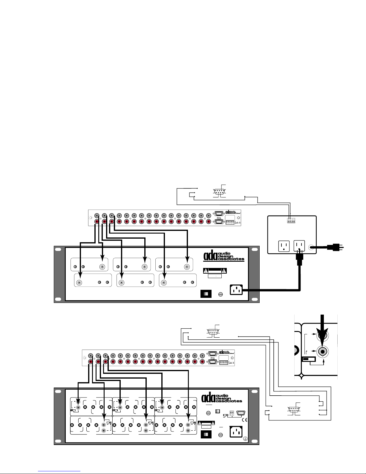
Amp Trigger Jumping on 9-Pin D Connectors
CAUTION
RISK OF ELECTRIC SHOCK
DO NOT OPEN
ATTENTION!
RISQUE DE CHOC ELECTRIQUE.
NE PAS OUVRIR
MADE IN U.S.A.
When more than just a few zones require greater power, several ADA amplifiers options exist
including the PTM-6150 (6 x 150W/Ch @ 8Ω, 250W/Ch @ 4Ω, stable to 2Ω), PTM-8150 (8 x
150W/Ch @ 8Ω, 250W/Ch @ 4Ω, stable to 2Ω), and PTM-1260 (operating in bridged mode 6 x 175W/Ch @ 8Ω, 350W/Ch @ 4Ω, stable to 4Ω). While the PTM-1260 has zoned triggers
built-in, the PTM-6150 and PTM-8150 will require an ACC-3 to turn them on. Again, one can
combine zone triggers together to engage a single amplifier, even if it is powering more than
one zone.
There are two ways one can combine triggers together. ADA suggests using the DB-9 9-Pin
Termination Block but you can also cut and splice a ribbon cable. If you choose to use the
DB-9, you will need one for every P-16 D connector you will be triggering from and another for
every PTM-1260 that is running in bridged mode. When doing so, remember to switch the
appropriate channels to bridged mode on the back of the PTM-1260 and that in this mode, the
amplifier is only stable to 4Ω. The PTM-1260 can be bridged from 12, to 10, 8, or 6 channels.
Male Connector
Plugs Into P-16 DB-9 Jack
The diagram below shows a PTM6150 with Ch. 1 & 2 = zone 1, Ch. 3 &
4 = zone 2, and Ch. 5 & 6 = zone 3.
1
23 4567 8910111213141516
L
R
P-16
(on DB-9 or Ribbon Cable)
Pin 1/Gnd
Pin 6/Zone 1
Pin 7/Zone 2
Zones 1-6
Zones 7-12
Zones 1- 6 & 7-12
TO PTM-1225/1260
In 6/12
In 5/11
In 4/10
In 3/9
+12VDC Outputs
Pin 4/Zone 6
Pin 5/Zone 5
Pin 9/Zone 4
Pin 8/Zone 3
P-16 • Preamplifier Module
Zones 13-16
Gnd
+12VDC Output
In 1/7
Gnd
In 2/8
(-)13(+)14(+)15(+)16(+)
1234
-A+ -B+
ACC-3
PIN 1 (-)
PIN 2 (+)
ACC-3
CAUTION! DO NOT SHORT OUTPUTS!
Ω
+-
CH 1
CH 4
INPUT
47K
OUTPUT 4-16
RISK OF HAZARDOUS
MAKE PROPER SPEAKER
OUTPUT 4-16
INPUT
47K
Ω
Ω
Ω
-+
WARNING!
ENERGY!
CONNECTIONS.
Manufactured under license
from Lucasfilm Ltd.
OUTPUT 4-16
Ω
+-
CH 2
INPUT
Ω
47K
CH 5
AVERTISSEMENT! ENERGIE
ELECTRIQUE DANGEREUSE! FAIRE
DES CONNEXIONS PROPRES POUR
L'HAUTPARLEUR. VOIR LA NOTICE
DE FONCTIONNEMENT.
INPUT
47K
OUTPUT 4-16
Lucasfilm and THX are registered
trademarks of Lucasfilm Ltd.
OUTPUT 4-16
Ω
INPUT
Ω
47K
-+
CAUTION: DISCONNECT SUPPLY CORD
ATTENTION: DEBRANCHER AVANT
Ω
+-
Ω
CH 6
BEFORE SERVICING.
LE DEPANNAGE.
The diagram below shows a PTM-1260
in bridged mode for all channels such
that Ch. 1 & 2 = zone 1, Ch. 3 & 4 =
zone 2, and Ch. 5 & 6 = zone 3.
1
23 4567 8910111213141516
L
R
Z
ONE
1
L
EFT
-
TEREO
COM COM
B
RIDGED
B
RIDGED
/ 4
-
+
-
IGHT
/ 7L
R
WARNING! RISK OF HAZARDOUS
ENERGY! MAKE PROPER SPEAKER
CONNECTIONS.
/ 1
+
+
+
+
EFT
Z
ONE
4
L
S
R
COM COM
PTM-1260 P
R
IGHT
/ 2
L
-
+
S
TEREO
R
-
B
RIDGED
/ 1
B
RIDGED
S
TEREO
-
/ 8
COM COM
B
RIDGED
B
RIDGED
-
COM COM
R
+
-
L
IGHT
/ 9L
R
AVERTISSEMENT! ENERGIE ELECTRIQUE DANGEREUSE!
FAIRE DES CONNEXIONS PROPRES POUR
L'HAUTPARLEUR. VOIR LA NOTICE DE FONCTIONNEMENT.
Z
L
EFT
-
/ 5
Z
OWER AMP
ONE
2
/ 3
+
+
B
RIDGED
+
+
-
EFT
/ 10
ONE
5
P-16
R
IGHT
/ 4
L
-
+
S
TEREO
R
-
B
RIDGED
/ 2
B
RIDGED
COM COM
R
S
TEREO
+
L
R
IGHT
/ 11
CAUTION: DISCONNECT SUPPLY CORD BEFORE SERVICING.
ATTENTION: DEBRANCHER AV LE DEPANNAGE.
L
-
COM COM
B
RIDGED
/ 6
-
-
INPUT
Ω
47K
CH 3
OUTPUT 4-16
Ω
-+
Plugs Into P-16 DB-9 Jack
(on DB-9 or Ribbon Cable)
Pin 1/Gnd
Pin 6/Zone 1
Pin 7/Zone 2
Z
ONE
3
EFT
/ 5
R
IGHT
/ 6
+
-
+
REPLACE WITH SAME VALUE FUSE
-
+
B
RIDGED
/ 3
B
RIDGED
+
+
L
Z
ONE
R
S
TEREO
-
L
EFT
/ 12
6
PTM-6150 P
REPLACE
VOLTAGE
WITH SAME
SWITCH
VALUE FUSE
115 V - 230 V
10A S.B.
115 V
Male Connector
Pin 4/Zone 6
Pin 5/Zone 5
Pin 9/Zone 4
Pin 8/Zone 3
Zones 1- 6 & 7-12
Zones 1-6
P-16 • Preamplifier Module
Zones 13-16
TO PTM-1225/1260
In 6/12
In 5/11
Gnd
+12VDC Output
In 1/7
In 4/10
Gnd
In 3/9
In 2/8
(-)13(+)14(+)15(+)16(+)
Zones 7-12
+12VDC Outputs
STANDBY
2/10A S.B.~115V
1/10A S.B.~230V
115 V
VOLTAGE
SWITCH
B
115 V~ /
230 V~
CAUTION
RISK OF ELECTRIC SHOCK
DO NOT OPEN
ATTENTION!
NE PAS OUVRIR
115 V~ / 230 V~
MAIN
REPLACE
WITH SAME
VALUE FUSE
115 V
10A S.B.~115V
5A S.B.~230V
RISQUE DE CHOC ELECTRIQUE.
MADE IN U.S.A.
VOLTAGE SWITCH
OWER AMP
POWER
115 V - 230 V
50 Hz - 60 Hz
ALL Z
ONES
DC T
RIGGER
1 2
(-) (+)
T
RIGGER
S
WITCH
E
XTERNAL
DC T
YPASS
115 V~ / 230 V~
50 Hz / 60 Hz
POWER
Set To
Bridged
L
STEREO
R
M
BRIDGED
IN
D C
ONNECTOR
9-P
O
PERATES DELTA
-88
Z
ONE TRIGGERS
1-6 O
NLY
RIGGERS
1500W
Pin 1/Gnd
Pin 6/Brdg 1
Pin 7/Brdg 2
Male Connector
Plugs Into PTM-1260 DB-9 Jack
(on DB-9 or Ribbon Cable)
Pin 4/Brdg 6
Pin 5/Brdg 5
Pin 9/Brdg 4
Pin 8/Brdg 3
- 17 -
Page 19
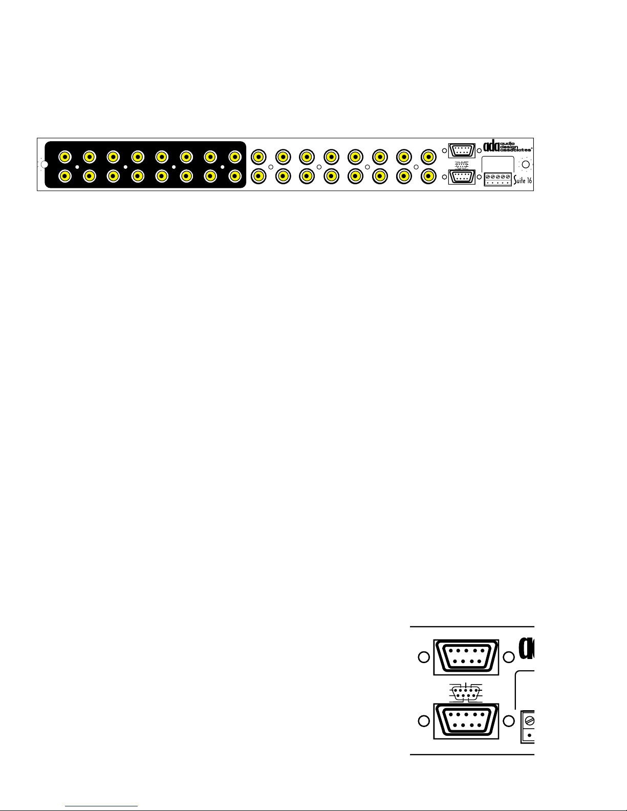
V-16 Video Switching Module
1
p
o
5
The V-16 Video Switching Module expands Suite 16’s distribution capabilities to include composite video as well as audio routing. Much like the P-16 Modules, the V-16 can be used in
multiples for up to 96 zones of video switching (up to six V-16 Modules).
Output Triggers
VIDEO INPUTS VIDEO OUTPUTS
13579111315
2 4 6 8 10 12 14 16
13579111315
V-16
2 4 6 8 10 12 14
Video Inputs
The V-16 features sixteen video inputs per V-16 Module. When using multiple V-16 Modules,
one must Y split the composite video signal of a source component to distribute it to more
than one V-16. The V-16 features Hi-Z termination making video splitting possible without
signal loss.
Video Outputs
The V-16 features sixteen video outputs per V-16 Module. These can be connected to TVs,
monitors, plasma TVs, projectors, video touch-screen controls, etc.
Video/Audio Tracking
The V-16 can be programmed in software such that any of its sixteen inputs tracks the corresponding audio input. As such, when either a DSS, DVD, VCR, or computer game input is
selected, the appropriate video signal can automatically be routed to the room’s TV or other
video display. Alternately, video inputs can be selected independently of audio signals, ideal
when one might want to listen to music while viewing a stock-ticker or sporting event.
Out 1-8
Out 6/14
Out 5/13
Out 4/12
Out 3/11
16
Out 9-16
+12VDC Outputs
Out 7/15
V-16 • Video I/O Module
Programmed Video
Out 8/16
Gnd
Out 1/9
Gnd
Out 2/10
(-)1(+)2(+)3(+)
Input Triggers
Input Triggers
5-24V AC•DC
4
(+)
Video Options
Because the V-16 has sixteen video inputs and sixteen video outputs, it may have more
connections than one might think can be used in a single system. For example, one might
only have 10 audio/video sources, 6 audio only sources, and only 8 rooms with a video display. That would leave six video inputs and eight video outputs unused. This may leave open
the door to include up to 6 closed-circuit TV cameras which could be switched to any of the 8
TVs. On the output side, the eight unused video outputs could be used to drive video-capable
touch screen controls. This makes the V-16 not just an ideal video switcher for entertainment
purposes, but also ideal for integration of security cameras and touch screen preview video
displays.
Video Output Triggers
The V-16 features two 9-pin “D” type connectors (non-RS-232) that
Output Triggers
ut 1-8
engage a +12VDC signal when the corresponding video output is
selected. The top connector includes a common ground pin and the
eight other pins correspond to video outputs 1-8. The bottom connector also features a common ground pin with the remaining eight
pins corresponding to video outputs 9-16. These triggers can be
used to trigger video monitors or other source devices when a video
output is selected.
Out 6/14
Out 5/13
Out 4/12
Out 3/11
t 9-16
Out 7/15
+12VDC Outputs
Out 8/16
Gnd
Out 1/9
Out 2/10
V-
Pr
Gnd
(-)
In
I
- 18 -
Page 20
e
Programmed Video Triggers
G
d
n
V
6
The V-16 also features five programmed triggers. The removable
5-pin screw terminal connector features ground (-) on pin 1, and 324V AC or DC input voltage sensing triggers on pins 2-5. These are
used to engage multiple switching functions in that are programmed
by the installer. All four triggers can also be serially engaged. The
fifth trigger can only be engaged via serial control.
V-16 • Video I/O Modul
Programmed Video
/16
Input Triggers
5-24V AC•DC
/9
Gnd
/10
(-)1(+)2(+)3(+)4(+)
Interactive Use of Triggers
Input Triggers
The video triggers can engage more than just a single video input
when a trigger is activated.
For example, the main entrance of the home has the door bell set to engage an audio and
video trigger. The audio trigger is set to line-sensing using the door chime mechanism as the
audio trigger source. When the door bell is pressed, the chime will play through selected
rooms using the audio sensing paging input. The main entrance also has two closed circuit
TV cameras monitoring the doorway. These input into the V-16 module on inputs 14 and 16
(completely arbitrary inputs). When the door bell is pressed, not only will the chime play
through the system, but also the video cameras can be displayed. During setup, you can
determine which video outputs follow any one of the triggers. If an output is dedicated to a
video capable touch screen and that touch screen is set to monitor Trigger 1, then when the
door bell is pressed, that touch screen will get the cameras at the front door.
Cycle Count & Dwell Time
In the case where more than one camera is set to a specific trigger, the V-16 features both a
cycle count setting (1-99 cycles) and a dwell time setting (1-60 seconds). In the example
above, when the door bell is pressed, the touch screen will display both camera 1 and camera
2 where you can determine how long each camera is held in frame and how often the cycle
repeats itself. Cycle count and dwell time are global settings affecting all four triggers. All
sixteen inputs can be set to follow a trigger if desired. When only a single camera is set to a
trigger, its image remains steady even if numerous cycles are employed due to the requirements of other triggers.
1
2 3 4 5 6 7 8 9 10 11 12 13 14 15 16
L
R
1
2 3 4 5 6 7 8 9 10 11 12 13 14 15 16
L
R
13579111315
2 4 6 8 10 12 14 16
VIDEO INPUTS
EXPANSION PORTS
CAM 1
A-16
P-16
13579111315
V-16
2 4 6 8 10 12 14
CAM 2
Door Bell
16-24V
Transformer
Input Triggers
In 1-8
In 6/14
In 5/13
In 4/12
In 3/11
In 9-16
+12VDC Outputs
Zones 1- 6 & 7-12
Zones 1-6
In 6/12
In 5/11
In 4/10
In 3/9
Zones 7-12
+12VDC Outputs
Output Triggers
Out 1-8
Out 6/14
Out 5/13
Out 4/12
Out 3/11
16
Out 9-16
+12VDC Outputs
Door Bell
Chime
120VAC
Network Control I/O
1 Gnd
In 7/15
TO PTM-1225/1260
Out 7/15
A-16 • Audio Input Module
Balanced
In 8/16
Audio Page
Gnd
Input (600Ω)
In 1/9
1
In 2/10
Com
Paging Input/Trigger
P-16 • Preamplifier Module
Gnd
+12VDC Output
In 1/7
Gnd
In 2/8
(-)13(+)14(+)15(+)16(+)
V-16 • Video I/O Module
Programmed Video
Out 8/16
Gnd
Out 1/9
Gnd
Out 2/10
(-)1(+)2(+)3(+)
Input Triggers
2
(+)3(-)4(+)5(-)
Zones 13-16
Input Triggers
5-24V AC•DC
2 Fdbk
Trigger
5-24V
3 Cntrl
AC•DC
4 +V
ADA Bus®
230V
115 V
115V
1/2 ASB
115V~
WARNING! Risk Of Hazardous Energy!
Make Proper Connections.
1/4 ASB
AVERTISSEMENT! Energie Electrique
230V~
Switch
AC
(10A)
4
(+)
Main
AC
Input
Dangereuse!
Faire Des Connexions Propres
Pour L'Hautparleur.
Voir La Notice De Fonctionnement.
CAUTION: Disconnect Supply
Cord Before Servicing.
ATTENTION: Debrancher
Avant Le Depannage.
115V~/60Hz • 230V~/50Hz
500 WATTS MAX
CAUTION
RISK OF ELECTRIC SHOCK
DO NOT OPEN
ATTENTION!
RISQUE DE CHOC ELECTRIQUE.
NE PAS OUVRIR
MADE IN U.S.A.
AVP-16 MR Controller
Audio Out
(Line-Level)
If chime has no audio output, create
line level using resistors across the
chime speaker.
- 19 -
Chime
Speaker
6
Zones 7-12
Zones 1-6
Out 1-8
Out 9-16
In 9-16
Out 6/14
Out 5/13
Out 4/12
Out 3/11
In 7/15
In 6/14
In 5/13
In 4/12
In 3/11
+12VDC Outputs
Zones 1- 6 & 7-12
TO PTM-1225/1260
In 6/12
In 5/11
In 4/10
In 3/9
+12VDC Outputs
Output Triggers
Out 7/15
+12VDC Outputs
A-16 • Audio Input Module
Balanced
In 8/16
Audio Page
Gnd
Input (600Ω)
In 1/9
1
2
In 2/10
(+)3(-)4(+)5(-)
Com
Paging Input/Trigger
P-16 • Preamplifier Module
Zones 13-16
Gnd
+12VDC Output
In 1/7
Gnd
In 2/8
(-)13(+)14(+)15(+)16(+)
V-16 • Video I/O Module
Programmed Video
Out 8/16
Input Triggers
Gnd
5-24V AC•DC
Out 1/9
Gnd
Out 2/10
(-)1(+)2(+)3(+)
Input Triggers
230V
115V
1/2 ASB
115V~
1/4 ASB
230V~
Switch
AC
(10A)
Main
AC
Input
ADA Bus®
115 V
2 F
3 C
4 +
Trigg er
5-24V
AC•DC
4
(+)
Page 21
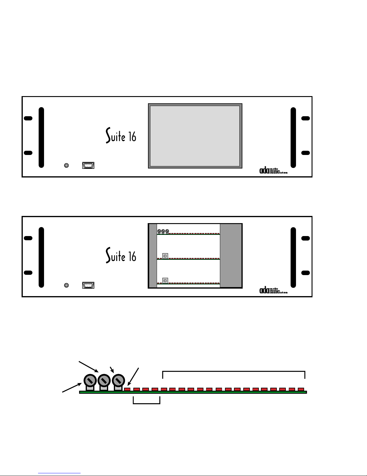
AVP-16 Baud Rate, Zone, & Paging Settings
The AVP-16 front panel is remarkably void of clutter. In addition to the main power switch, the
front panel RS-232 I/O, there is only a smoked plexiglass plate through which several LEDs
are visible. During setup, this plate may need to be removed to access options for the A-16,
P-16 or V-16 modules.
POWER RS-232
AVP-16
AVP-16 Plexiglass Plate Removal
There are four screws that secure the front panel plexiglass plate. To remove the plate,
simply remove these four screws.
0
POWER RS-232
AVP-16
0
A-16 Module Front Panel Setup
The A-16 Audio Input module features twenty LEDs which indicate the presence of voltage
(power), which inputs are active (1-16), and whether the audio trigger is engaged. The diagram below details these LEDs and also shows the position of three trim pots.
COMPRESSION
SLOPE
INPUT
LEVEL
AUDIO
TRIGGER
+V -V VD
ACTIVE AUDIO INPUTS (1-16)
1234 56 789101112131415
16
TRIGGER
LEVEL
POWER
SUPPLY
+/-V = ANALOG VOLTAGE
VD = DIGITAL VOLTAGE
- 20 -
Page 22
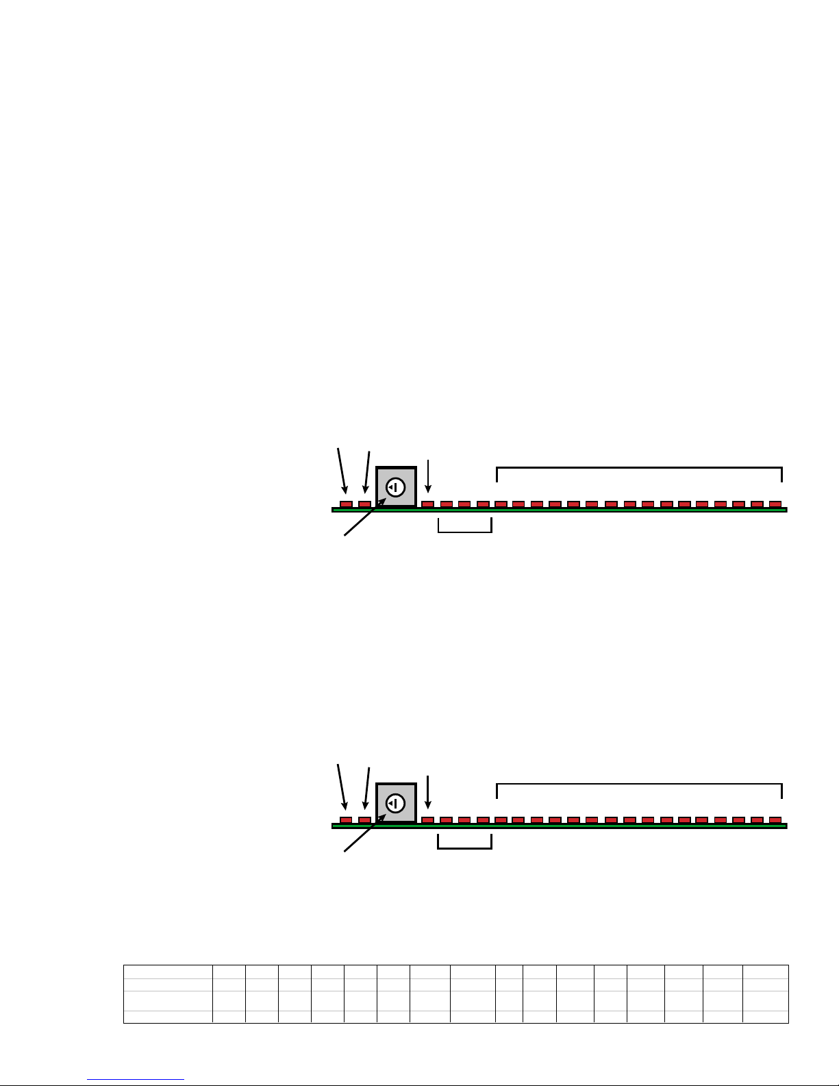
The compression slope trim pot is used to compress the paging audio input signal. This
(
)
feature will prevent an input signal that is too high from being broadcast at that level. While
each room has its own paging volume level to prevent speaker overdrive, the compression
slope adjustment is used to prevent the input signal from being distorted.
The input level adjustment trim pot is used to determine the level of the audio input signal.
With this adjustment, low level signals can be raised or signals that are too hot can be lowered.
The trigger level trim pot is used to adjust the sensitivity of the audio input trigger. There are
a total of eight paging triggers. Six of these are serially controlled, one is a voltage trigger,
and one trigger is audio sensing. This trim pot is used to set this trigger such that it engages
and disengages appropriately.
P-16 Module Front Panel Setup
The P-16 Preamplifier module features twenty-two LEDs which indicate data transmission
and reception, the presence of voltage (power), which zones are active (1-16), and whether
the system is on. The
diagram below details
these LEDs and also
shows the position of
the address selector.
RX TX
MAIN
ON
0
+V -V VD
ACTIVE PREAMPLIFIER ZONES (1-16)
1234 56 789101112131415
16
The address selector
sets the address of
the P-16 module
since as many as six
P-16s can be used for
ADDRESS
SWITCH
POWER
SUPPLY
+/-V = ANALOG VOLTAGE
VD = DIGITAL VOLTAGE
up to 96 zones. Address “0” is the default address for zones 1-16 operating at a baud rate of 19200.
V-16 Module Front Panel Setup
The V-16 Video Switching module features twenty-two LEDs which indicate data transmission and reception, the presence of voltage (power), which outputs are active (1-16), and
whether the system is
on. The diagram below
details these LEDs and
RX TX
MAIN
ON
ACTIVE VIDEO ZONES (1-16)
also shows the position
of the address selector.
0
+V -V VD
1234 56 789101112131415
16
The address selector
sets the address of the
V-16 module since as
many as six V-16s can
be used for up to 96
ADDRESS
SWITCH
POWER
SUPPLY
+/-V = ANALOG VOLTAGE
VD = DIGITAL VOLTAGE
zones. Address “0” is
the default address for zones 1-16 operating at a baud rate of 19200.
Dial Address 012345 6 7 8910 (A)11 (B)12 (C) 13 (D) 14 (E) 15 (F)
P-16 Zones 1-16 17-32 33-48 49-64 61-80 81-96 N/A N/A 1-16 17-32 33-48 49-64 61-80 81-96 N/A N/A
V-16 Zones
NF=No Feedback
Baud Rate 19200 19200 19200 19200 19200 19200 19200 19200 1200 1200 1200 1200 1200 1200 1200 1200
1-16 17-32 33-48 49-64 61-80 81-96 NF 1-16 NF 17-32 1- 1 6 17-32 33-48 49-64 61-80 81-96 NF 1-16 NF 17-32
- 21 -
Page 23
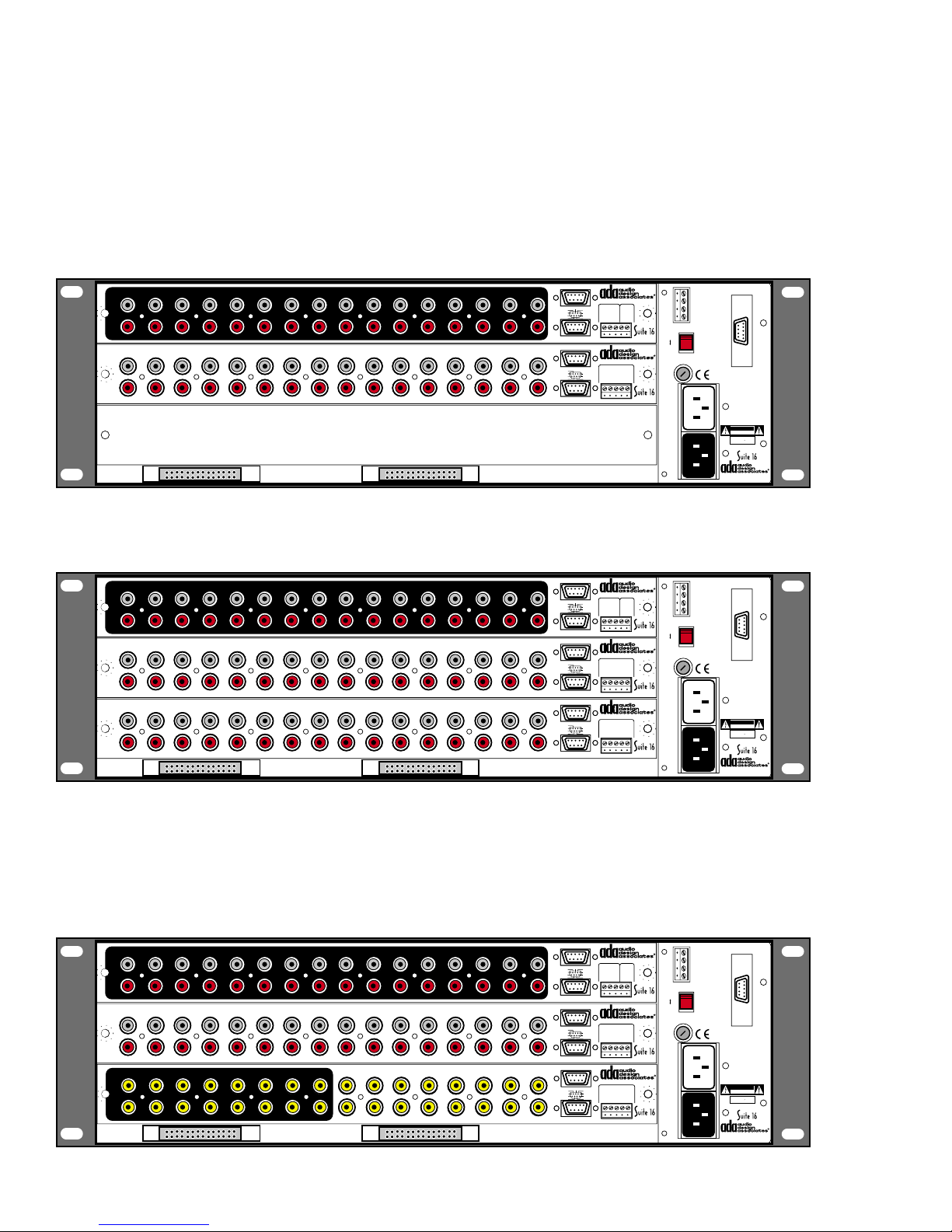
AVP-16 Configuration Options
The AVP-16 is the Suite 16 chassis that can house up to three cards. As both the A-16, P-16,
and V-16 are designed to be interchangeable, here are some options regarding configuration
of the primary AVP-16.
Basic Setup - One A-16 and One P-16
This configuration is the most basic of all Suite 16 options in which 16 audio components are
routed to 16 audio zones.
Input Triggers
1
2 3 4 5 6 7 8 9 10 11 12 13 14 15 16
L
R
1
2 3 4 5 6 7 8 9 10 11 12 13 14 15 16
L
R
A-16
P-16
In 1-8
In 9-16
Zones 1-6
Zones 7-12
In 7/15
In 6/14
In 5/13
In 4/12
In 3/11
+12VDC Outputs
Zones 1- 6 & 7-12
TO PTM-1225/1260
In 6/12
In 5/11
In 4/10
In 3/9
+12VDC Outputs
A-16 • Audio Input Module
Balanced
In 8/16
Audio Page
Gnd
Input (600Ω)
In 1/9
2
1
In 2/10
(+)3(-)4(+)5(-)
Com
Paging Input/Trigger
P-16 • Preamplifier Module
Zones 13-16
Gnd
+12VDC Output
In 1/7
Gnd
In 2/8
(-)13(+)14(+)15(+)16(+)
Trigg er
5-24V
AC•DC
Double Audio Setup - One A-16 & Two P-16s
This configuration adds an additional 16 zones for a total of 16 audio components to 32 audio
zones.
Input Triggers
1
2 3 4 5 6 7 8 9 10 11 12 13 14 15 16
L
R
1
2 3 4 5 6 7 8 9 10 11 12 13 14 15 16
L
R
1
2 3 4 5 6 7 8 9 10 11 12 13 14 15 16
L
R
A-16
P-16
P-16
In 1-8
In 9-16
Zones 1-6
Zones 7-12
Zones 1-6
Zones 7-12
In 7/15
In 6/14
In 5/13
In 4/12
In 3/11
+12VDC Outputs
Zones 1- 6 & 7-12
TO PTM-1225/1260
In 6/12
In 5/11
In 4/10
In 3/9
+12VDC Outputs
Zones 1- 6 & 7-12
TO PTM-1225/1260
In 6/12
In 5/11
In 4/10
In 3/9
+12VDC Outputs
A-16 • Audio Input Module
Balanced
In 8/16
Audio Page
Gnd
Input (600Ω)
In 1/9
1
2
In 2/10
(+)3(-)4(+)5(-)
Com
Paging Input/Trigger
P-16 • Preamplifier Module
Zones 13-16
Gnd
+12VDC Output
In 1/7
Gnd
In 2/8
(-)13(+)14(+)15(+)16(+)
P-16 • Preamplifier Module
Zones 13-16
Gnd
+12VDC Output
In 1/7
Gnd
In 2/8
(-)13(+)14(+)15(+)16(+)
Trigg er
5-24V
AC•DC
1/2 ASB
115V~
1/4 ASB
230V~
Switch
(10A)
Main
Input
1/2 ASB
115V~
1/4 ASB
230V~
Switch
(10A)
Main
Input
ADA Bus®
230V
115V
AC
AC
ADA Bus®
230V
115V
AC
AC
1 Gnd
Network Control I/O
2 Fdbk
3 Cntrl
4 +V
115 V
WARNING! Risk Of Hazardous Energy!
Make Proper Connections.
AVERTISSEMENT! Energie Electrique
Dangereuse!
Faire Des Connexions Propres
Pour L'Hautparleur.
Voir La Notice De Fonctionnement.
CAUTION: Disconnect Supply
Cord Before Servicing.
ATTENTION: Debrancher
Avant Le Depannage.
115V~/60Hz • 230V~/50Hz
500 WATTS MAX
CAUTION
RISK OF ELECTRIC SHOCK
DO NOT OPEN
ATTENTION!
RISQUE DE CHOC ELECTRIQUE.
NE PAS OUVRIR
MADE IN U.S.A.
AVP-16 MR Controller
Network Control I/O
1 Gnd
2 Fdbk
3 Cntrl
4 +V
115 V
WARNING! Risk Of Hazardous Energy!
Make Proper Connections.
AVERTISSEMENT! Energie Electrique
Dangereuse!
Faire Des Connexions Propres
Pour L'Hautparleur.
Voir La Notice De Fonctionnement.
CAUTION: Disconnect Supply
Cord Before Servicing.
ATTENTION: Debrancher
Avant Le Depannage.
115V~/60Hz • 230V~/50Hz
500 WATTS MAX
CAUTION
RISK OF ELECTRIC SHOCK
DO NOT OPEN
ATTENTION!
RISQUE DE CHOC ELECTRIQUE.
NE PAS OUVRIR
MADE IN U.S.A.
AVP-16 MR Controller
Basic Video Setup - One A-16, One P-16, and One V-16
This configuration adds video to the basic 16 audio sources to 16 zone configuration. Because the video card can have outputs either track or not track the 16 audio inputs, one can
treat the 16 video sources as additional inputs and outputs. For example, out of the 16 audio
sources, only 10 have a video signal. That would leave 6 video inputs available for non-audio
video input devices such as cameras.
1
2 3 4 5 6 7 8 9 10 11 12 13 14 15 16
L
R
1
2 3 4 5 6 7 8 9 10 11 12 13 14 15 16
L
R
13579111315
2 4 6 8 10 12 14 16
VIDEO INPUTS
EXPANSION PORTS
A-16
P-16
13579111315
V-16
2 4 6 8 10 12 14
16
- 22 -
In 1-8
In 9-16
Zones 1-6
Zones 7-12
Out 1-8
Out 9-16
Input Triggers
In 7/15
In 6/14
In 5/13
In 4/12
In 3/11
+12VDC Outputs
Zones 1- 6 & 7-12
TO PTM-1225/1260
In 6/12
In 5/11
In 4/10
In 3/9
+12VDC Outputs
Output Triggers
Out 7/15
Out 6/14
Out 5/13
Out 4/12
Out 3/11
+12VDC Outputs
A-16 • Audio Input Module
Balanced
In 8/16
Audio Page
Gnd
Input (600Ω)
In 1/9
1
2
In 2/10
(+)3(-)4(+)5(-)
Com
Paging Input/Trigger
P-16 • Preamplifier Module
Zones 13-16
Gnd
+12VDC Output
In 1/7
Gnd
In 2/8
(-)13(+)14(+)15(+)16(+)
V-16 • Video I/O Module
Programmed Video
Out 8/16
Input Triggers
Gnd
5-24V AC•DC
Out 1/9
Gnd
Out 2/10
(+)1(+)2(+)3(+)
Input Triggers
Network Control I/O
1 Gnd
1/2 ASB
115V~
1/4 ASB
230V~
Switch
(10A)
Main
Input
ADA Bus®
230V
115V
AC
AC
2 Fdbk
3 Cntrl
4 +V
115 V
WARNING! Risk Of Hazardous Energy!
Make Proper Connections.
AVERTISSEMENT! Energie Electrique
Dangereuse!
Faire Des Connexions Propres
Pour L'Hautparleur.
Voir La Notice De Fonctionnement.
CAUTION: Disconnect Supply
Cord Before Servicing.
ATTENTION: Debrancher
Avant Le Depannage.
115V~/60Hz • 230V~/50Hz
500 WATTS MAX
CAUTION
RISK OF ELECTRIC SHOCK
DO NOT OPEN
ATTENTION!
RISQUE DE CHOC ELECTRIQUE.
NE PAS OUVRIR
MADE IN U.S.A.
Trigg er
5-24V
AC•DC
4
(+)
AVP-16 MR Controller
Page 24
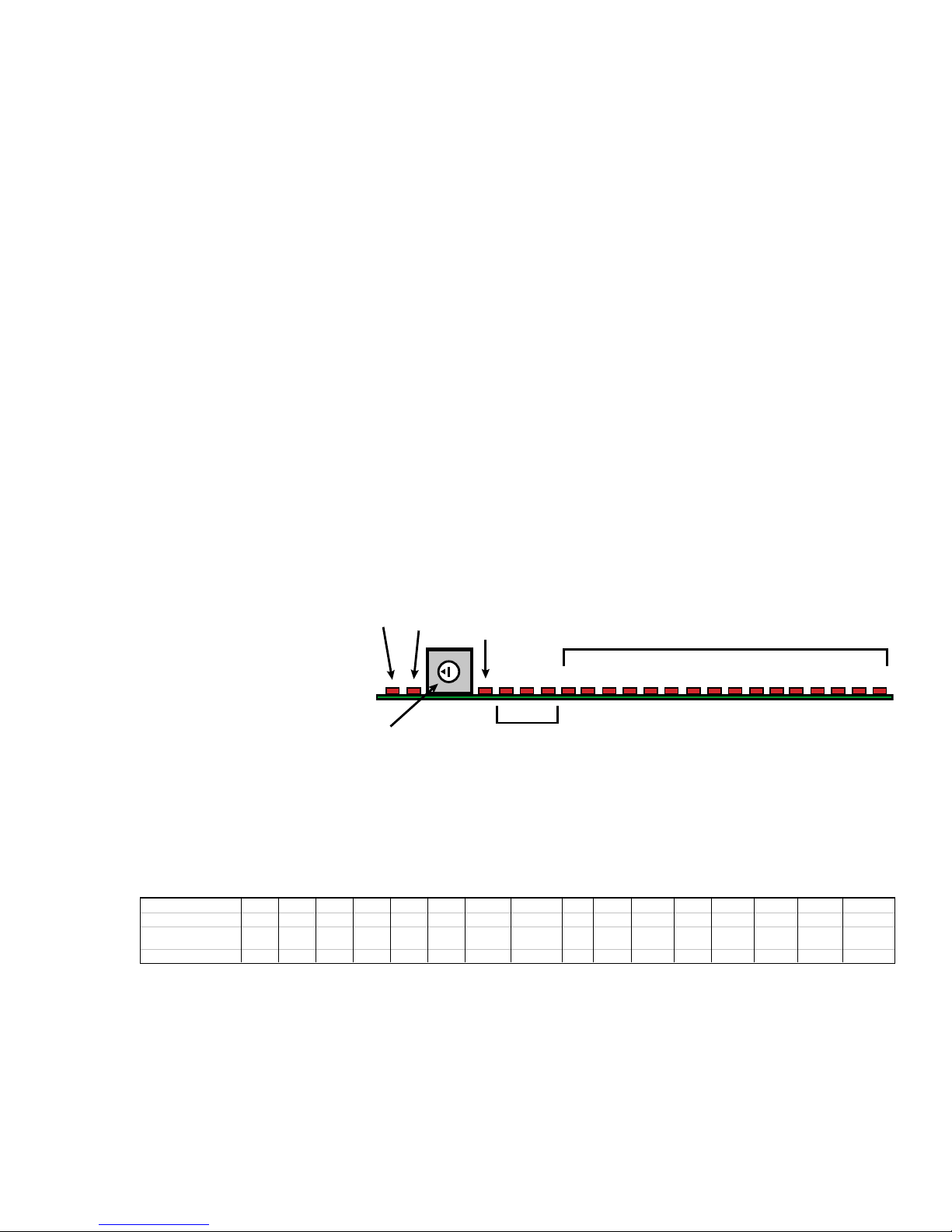
Matrix Switching - S-Video, Component, or RGBHV
(
)
For applications where an installation requires simultaneous switching of multiple discrete
video signals, any Suite-16 V-16 Video Module may be set up as a slave card. This is useful
for S-Video (Y & C), component video (Y, Cr, Cb), or HDTV video (RGBHV) switching. Furthermore, because of the Suite-16s value, configuration of a Suite 16 for matrix switching is
extremely competitive.
As such, a single video switching command can activate switching of inputs for more than just
a single V-16 module. For example, when using the S-Video configuration below, if video
input 1 is selected in room 1, both video cards (one for C and one for Y), will switch together.
There are special technical issues that do come into play when switching multiple videos
cards with a single command. In order for this feature to work, all V-16 modules need to be
set to the same room address. As such, when a single command is issued, all cards will
switch. The only problem that occurs when using standard V-16 addresses, stems from the
feedback created by all cards. As each card switches, it will return conformation of the switch
in the form of ASCII feedback. It is this feedback that may cause problems. As multiple cards
respond, the feeback may get corrupted. To prevent this from occurring when using the AVP16 and V-16 modules as a matrix switcher, ADA has added two additional V-16 addresses that
defeat feedback, preventing data corruption, while still permitting full control.
Changing of the V-16 Address
Located behind the removable plexiglass
panel on the front of the
AVP-16, each V-16
module has a rotary
RX TX
MAIN
ON
0
+V -V VD
ACTIVE VIDEO ZONES (1-16)
1234 56 789101112131415
16
DIP switch which sets
the address for the
card. There are a total
of sixteen address options. Address 0 refers
ADDRESS
SWITCH
POWER
SUPPLY
+/-V = ANALOG VOLTAGE
VD = DIGITAL VOLTAGE
to rooms 1-16 for systems operating at 19200. Address 1 is for rooms 17-32 at the same
baud rate. Alternately, address 9 is for rooms 1-16 for systems operating at 1200 baud while
address 10 (sometimes noted as address A) is for rooms 17-32 at the same baud rate.
Dial Address 012345 6 7 8910 (A)11 (B)12 (C) 13 (D) 14 (E) 15 (F)
P-16 Zones 1-16 17-32 33-48 49-64 61-80 81-96 N/A N/A 1-16 17-32 33-48 49-64 61-80 81-96 N/A N/A
V-16 Zones
NF=No Feedback
Baud Rate 19200 19200 19200 19200 19200 19200 19200 19200 1200 1200 1200 1200 1200 1200 1200 1200
1-16 17-32 33-48 49-64 61-80 81-96 NF 1-16 NF 17-32 1- 1 6 17-32 33-48 49-64 61-80 81-96 NF 1-16 NF 17-32
There are V-16 Video Module addresses that are specifically designed not to provide feeback.
Address 6 refers to rooms 1-16 at 19200 without feedback and Address 7 refers to rooms 1732 at 19200, also without feedback. For 1200 baud systems without feedback, address 14
(also known as address E) refers to rooms 1-16 while address 15 (also known as address F)
refers to rooms 17-32. These addresses are to be used on the second, third, fourth, and fifth
V-16 modules. The first module uses the standard address. Here it is important that all room
and baud rate groups match.
- 23 -
Page 25
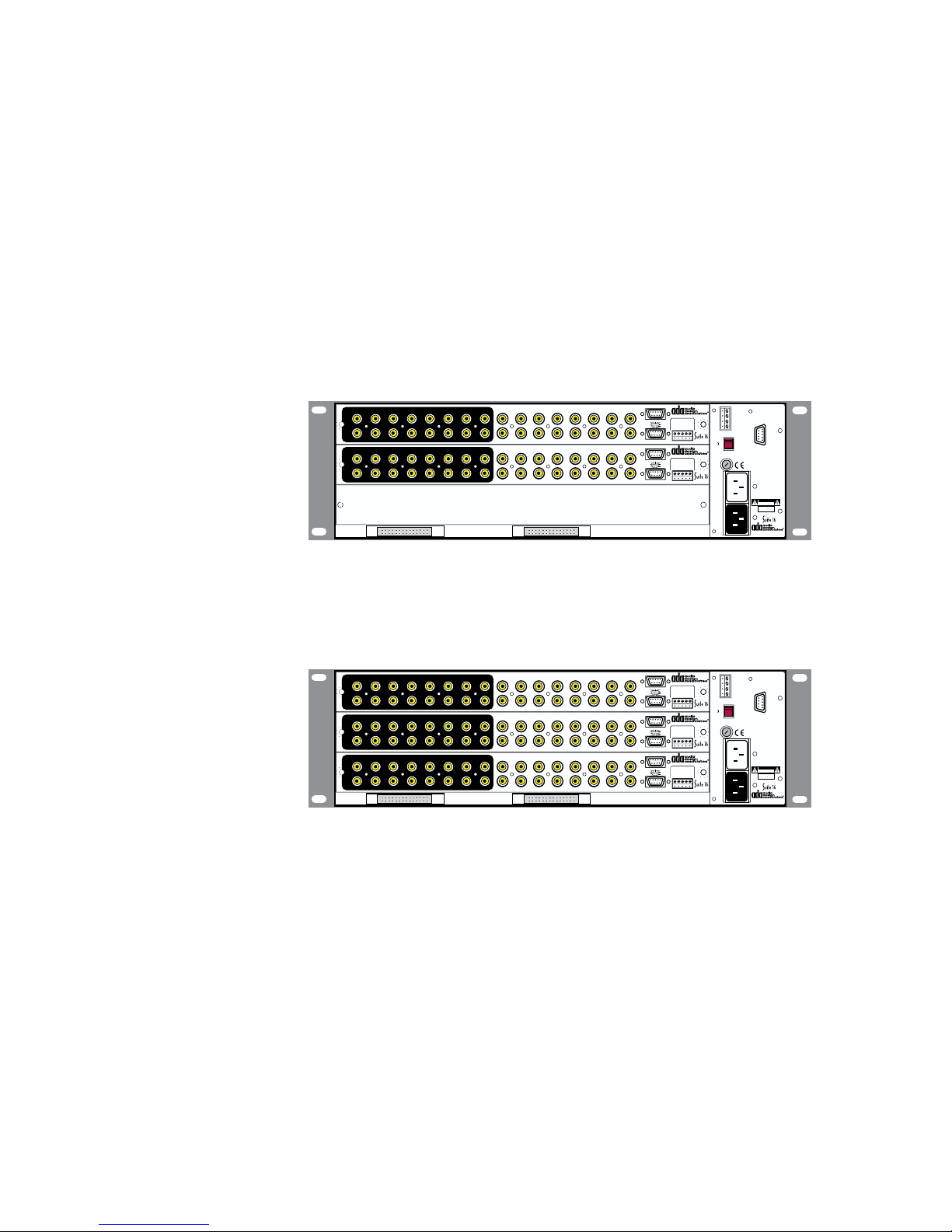
If you have a Suite-16 for 16 rooms that is switching composite video and you have a component video switching matrix in a separate AVP-16 chassis, then you might opt to use the room
group address of 17-32 for the matrix switcher. As such, you could connect the Suite-16
audio video system running 16 zones with composite video (addressed for rooms 1-16) and
the 16 x 16 component video matrix Suite 16 (set to room address 17-32) on the same ADA
Bus network without conflict.
In the event, you have 17 or more rooms on a Suite-16 setup for audio and video switching,
you will need to communicate to the Suite-16 setup for component video switching, through a
separate com port. Here you could opt to run the matrix switcher on any of the two room
group addresses, as this switcher is not going to be connected directly to the Suite-16 audio
video system.
S-Video Switching
This configuration uses a
single AVP-16 chassis outfitted with two V-16 modules.
One module is connected to
up to 16 S-Video “Y” outputs.
The second module connects
the “C” S-Video outputs. The
13579111315
2 4 6 8 10 12 14 16
13579111315
2 4 6 8 10 12 14 16
VIDEO INPUTS
VIDEO INPUTS
EXPANSION PORTS
13579111315
V-16
2 4 6 8 10 12 14
13579111315
V-16
2 4 6 8 10 12 14
Output Triggers
Out 1-8
V-16 Video I/O Module
Programmed Video
Out 7/15
Out 8/16
Out 6/14
Input Triggers
Gnd
Out 5/13
5-24V AC DC
Out 1/9
Out 4/12
Gnd
Out 3/11
Out 2/10
Out 9-16
Out 1-8
Out 9-16
+12VDC Outputs
Output Triggers
Out 6/14
Out 5/13
Out 4/12
Out 3/11
+12VDC Outputs
(-)1(+)2(+)3(+)4(+)
Input Triggers
V-16 Video I/O Module
Programmed Video
Out 7/15
Out 8/16
Input Triggers
Gnd
5-24V AC DC
Out 1/9
Gnd
Out 2/10
(-)1(+)2(+)3(+)4(+)
Input Triggers
16
16
Network Control I/O
1 Gnd
2 Fdbk
3 Cntrl
4 +V
ADA Busfi
230V
115 V
115V
1/2 ASB
115V~
WARNING! Risk Of Hazardous Energy!
Make Proper Connections.
1/4 ASB
AVERTISSEMENT! Energie Electrique
230V~
Switch
AC
(10A)
Main
AC
Input
Dangereuse!
Faire Des Connexions Propres
Pour L’Hautparleur.
Voir La Notice De Fonctionnement.
CAUTION: Disconnect Supply
Cord Before Servicing.
ATTENTION: Debrancher
Avant Le Depannage.
115V~/60Hz 230V~/50Hz
500 WATTS MAX
CAUTION
RISK OF ELECTRIC SHOCK
DO NOT OPEN
ATTENTION!
RISQUE DE CHOC ELECTRIQUE.
NE PAS OUVRIR
MADE IN U.S.A.
AVP-16 MR Controller
end result is a 16 x 16 S-Video switcher. Here the first card needs to be set to the 0 address
while the second unit is set to address 6. You can also uses addresses 1 and 7 respectively.
For 1200 baud systems, addresses 8 and 14 could be used or addresses 9 and 15.
Component Video Switching
This configuration uses a
single AVP-16 chassis outfitted with three V-16 modules.
One module is connected to
up to 16 “Y” outputs. The
second module connects the
13579111315
2 4 6 8 10 12 14 16
13579111315
2 4 6 8 10 12 14 16
13579111315
2 4 6 8 10 12 14 16
VIDEO INPUTS
VIDEO INPUTS
VIDEO INPUTS
EXPANSION PORTS
13579111315
V-16
2 4 6 8 10 12 14
13579111315
V-16
2 4 6 8 10 12 14
13579111315
V-16
2 4 6 8 10 12 14
Output Triggers
Out 1-8
V-16 Video I/O Module
Programmed Video
Out 7/15
Out 8/16
Out 6/14
Input Triggers
Gnd
Out 5/13
5-24V AC DC
Out 1/9
Out 4/12
Gnd
Out 3/11
Out 2/10
Out 9-16
Out 1-8
Out 9-16
Out 1-8
Out 9-16
+12VDC Outputs
Output Triggers
Out 6/14
Out 5/13
Out 4/12
Out 3/11
+12VDC Outputs
Output Triggers
Out 6/14
Out 5/13
Out 4/12
Out 3/11
+12VDC Outputs
(-)1(+)2(+)3(+)4(+)
Input Triggers
V-16 Video I/O Module
Programmed Video
Out 7/15
Out 8/16
Input Triggers
Gnd
5-24V AC DC
Out 1/9
Gnd
4
Out 2/10
(-)1(+)2(+)3(+)
(+)
Input Triggers
V-16 Video I/O Module
Programmed Video
Out 7/15
Out 8/16
Input Triggers
Gnd
5-24V AC DC
Out 1/9
Gnd
Out 2/10
(-)1(+)2(+)3(+)4(+)
Input Triggers
16
16
16
Network Control I/O
1 Gnd
2 Fdbk
3 Cntrl
4 +V
ADA Busfi
230V
115 V
115V
1/2 ASB
115V~
WARNING! Risk Of Hazardous Energy!
Make Proper Connections.
1/4 ASB
AVERTISSEMENT! Energie Electrique
230V~
Switch
AC
(10A)
Main
AC
Input
Dangereuse!
Faire Des Connexions Propres
Pour L’Hautparleur.
Voir La Notice De Fonctionnement.
CAUTION: Disconnect Supply
Cord Before Servicing.
ATTENTION: Debrancher
Avant Le Depannage.
115V~/60Hz 230V~/50Hz
500 WATTS MAX
CAUTION
RISK OF ELECTRIC SHOCK
DO NOT OPEN
ATTENTION!
RISQUE DE CHOC ELECTRIQUE.
NE PAS OUVRIR
MADE IN U.S.A.
AVP-16 MR Controller
“Cr” component outputs. The
third card connects the “Cb” component outputs. The end result is a 16 x 16 component video
switcher. Here the first card needs to be set to the 0 address while the second and third cards
are set to address 6. You can also uses addresses 1 and 7 respectively. For 1200 baud
systems, addresses 8 and 14 could be used or addresses 9 and 15.
RGBHV Video Switching
This configuration uses a two AVP-16 chassis outfitted with three V-16 modules in the first
chassis and two in the second. One module is connected to up to 16 “R” outputs. The second
module connects the “G” video outputs. The third card connects the “B” video outputs. In the
second chassis, the first card is connect to the “H” video outputs and the second card is
connected to the “V” video outputs. The end result is a 16 x 16 component video switcher.
Here the first card needs to be set to the 0 address while the second, third, fourth, and fifth
cards are set to address 6. You can also uses addresses 1 and 7 respectively. For 1200 baud
systems, addresses 8 and 14 could be used or addresses 9 and 15. An RGBHV switcher is
a combination of the two diagrams above.
- 24 -
Page 26
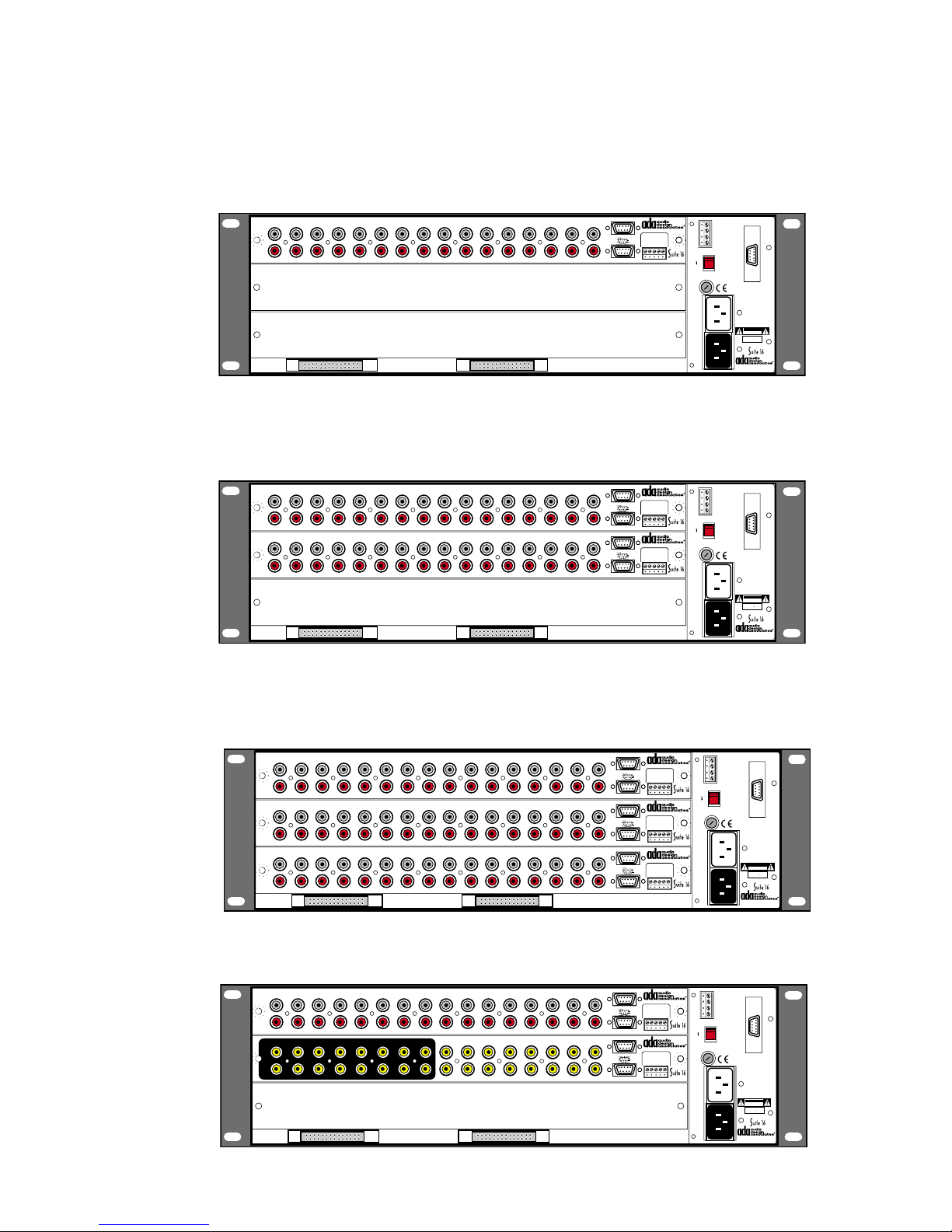
AVP-16 Slave-Unit Configuration Options
Slave Audio Setup - In addition to the first AVP-16, a 2nd chassis w/One P-16
This configuration is in addition to the primary AVP-16 and as such, does not require an A-16
Audio Input Module. This chassis adds 16 zones to the primary unit.
Zones 1- 6 & 7-12
1
2 3 4 5 6 7 8 9 10 11 12 13 14 15 16
L
R
P-16
Zones 1-6
Zones 7-12
TO PTM-1225/1260
In 6/12
In 5/11
In 4/10
In 3/9
+12VDC Outputs
P-16 • Preamplifier Module
Zones 13-16
Gnd
+12VDC Output
In 1/7
Gnd
In 2/8
(-)13(+)14(+)15(+)16(+)
Slave Audio Setup - In addition to the first AVP-16, a 2nd chassis w/ Two P-16s
This configuration adds 32 zones to those in the first chassis. If the first chassis houses two
P-16s and the second houses two P-16s, the zone count is 64.
Zones 1- 6 & 7-12
Zones 7-12
Zones 7-12
Zones 1-6
Zones 1-6
TO PTM-1225/1260
In 6/12
In 5/11
In 4/10
In 3/9
+12VDC Outputs
Zones 1- 6 & 7-12
TO PTM-1225/1260
In 6/12
In 5/11
In 4/10
In 3/9
+12VDC Outputs
P-16 • Preamplifier Module
Zones 13-16
Gnd
+12VDC Output
In 1/7
Gnd
In 2/8
(-)13(+)14(+)15(+)16(+)
P-16 • Preamplifier Module
Zones 13-16
Gnd
+12VDC Output
In 1/7
Gnd
In 2/8
(-)13(+)14(+)15(+)16(+)
1
2 3 4 5 6 7 8 9 10 11 12 13 14 15 16
L
R
1
2 3 4 5 6 7 8 9 10 11 12 13 14 15 16
L
R
P-16
P-16
Network Control I/O
1 Gnd
2 Fdbk
3 Cntrl
4 +V
ADA Bus®
230V
115 V
115V
1/2 ASB
115V~
1/4 ASB
230V~
Switch
AC
(10A)
Main
AC
Input
WARNING! Risk Of Hazardous Energy!
Make Proper Connections.
AVERTISSEMENT! Energie Electrique
Dangereuse!
Faire Des Connexions Propres
Pour L'Hautparleur.
Voir La Notice De Fonctionnement.
CAUTION: Disconnect Supply
Cord Before Servicing.
ATTENTION: Debrancher
Avant Le Depannage.
115V~/60Hz • 230V~/50Hz
500 WATTS MAX
CAUTION
RISK OF ELECTRIC SHOCK
DO NOT OPEN
ATTENTION!
RISQUE DE CHOC ELECTRIQUE.
NE PAS OUVRIR
MADE IN U.S.A.
AVP-16 MR Controller
Network Control I/O
1 Gnd
2 Fdbk
3 Cntrl
4 +V
ADA Bus®
230V
115 V
115V
1/2 ASB
115V~
1/4 ASB
230V~
Switch
AC
(10A)
Main
AC
Input
WARNING! Risk Of Hazardous Energy!
Make Proper Connections.
AVERTISSEMENT! Energie Electrique
Dangereuse!
Faire Des Connexions Propres
Pour L'Hautparleur.
Voir La Notice De Fonctionnement.
CAUTION: Disconnect Supply
Cord Before Servicing.
ATTENTION: Debrancher
Avant Le Depannage.
115V~/60Hz • 230V~/50Hz
500 WATTS MAX
CAUTION
RISK OF ELECTRIC SHOCK
DO NOT OPEN
ATTENTION!
RISQUE DE CHOC ELECTRIQUE.
NE PAS OUVRIR
MADE IN U.S.A.
AVP-16 MR Controller
Slave Audio Setup - In addition to the first AVP-16, a 2nd chassis w/ Three P-16s
This configuration adds 48 zones to those in the first chassis. If the first chassis houses two
P-16s and the second houses three P-16s, the zone count is 80.
Zones 1- 6 & 7-12
Zones 7-12
Zones 7-12
Zones 7-12
Zones 1-6
Zones 1-6
Zones 1-6
TO PTM-1225/1260
In 6/12
In 5/11
In 4/10
In 3/9
+12VDC Outputs
Zones 1- 6 & 7-12
TO PTM-1225/1260
In 6/12
In 5/11
In 4/10
In 3/9
+12VDC Outputs
Zones 1- 6 & 7-12
TO PTM-1225/1260
In 6/12
In 5/11
In 4/10
In 3/9
P-16 • Preamplifier Module
Zones 13-16
Gnd
+12VDC Output
In 1/7
Gnd
In 2/8
(-)13(+)14(+)15(+)16(+)
P-16 • Preamplifier Module
Zones 13-16
Gnd
+12VDC Output
In 1/7
Gnd
In 2/8
(-)13(+)14(+)15(+)16(+)
P-16 • Preamplifier Module
Zones 13-16
Gnd
+12VDC Output
In 1/7
Gnd
In 2/8
(-)13(+)14(+)15(+)16(+)
1
2 3 4 5 6 7 8 9 10 11 12 13 14 15 16
L
R
1
2 3 4 5 6 7 8 9 10 11 12 13 14 15 16
L
R
1
2 3 4 5 6 7 8 9 10 11 12 13 14 15 16
L
R
P-16
P-16
P-16
Slave Audio Setup - In addition to the first AVP-16, a second chassis w/ One P-16 &
One V-16
Zones 1- 6 & 7-12
1
2 3 4 5 6 7 8 9 10 11 12 13 14 15 16
L
R
13579111315
VIDEO INPUTS
2 4 6 8 10 12 14 16
P-16
13579111315
V-16
2 4 6 8 10 12 14
EXPANSION PORTS
Zones 1-6
P-16 • Preamplifier Module
Zones 13-16
TO PTM-1225/1260
In 6/12
In 5/11
Gnd
+12VDC Output
In 1/7
In 4/10
Gnd
In 2/8
In 3/9
(-)13(+)14(+)15(+)16(+)
Zones 7-12
+12VDC Outputs
Output Triggers
Out 1-8
V-16 • Video I/O Module
1/2 ASB
Programmed Video
Out 7/15
Out 8/16
Out 6/14
Gnd
Out 5/13
Out 1/9
Out 4/12
Gnd
Out 3/11
Out 2/10
Out 9-16
(+)1(+)2(+)3(+)
+12VDC Outputs
16
Input Triggers
5-24V AC•DC
Input Triggers
115V~
4
1/4 ASB
(+)
230V~
Switch
(10A)
Main
Input
230V
115V
1/2 ASB
115V~
1/4 ASB
230V~
Switch
AC
(10A)
Main
AC
Input
ADA Bus®
230V
115V
AC
AC
ADA Bus®
115 V
Network Control I/O
1 Gnd
2 Fdbk
3 Cntrl
4 +V
115 V
WARNING! Risk Of Hazardous Energy!
Make Proper Connections.
AVERTISSEMENT! Energie Electrique
Dangereuse!
Faire Des Connexions Propres
Pour L'Hautparleur.
Voir La Notice De Fonctionnement.
CAUTION: Disconnect Supply
Cord Before Servicing.
ATTENTION: Debrancher
Avant Le Depannage.
115V~/60Hz • 230V~/50Hz
500 WATTS MAX
CAUTION
RISK OF ELECTRIC SHOCK
DO NOT OPEN
ATTENTION!
RISQUE DE CHOC ELECTRIQUE.
NE PAS OUVRIR
MADE IN U.S.A.
AVP-16 MR Controller
Network Control I/O
1 Gnd
2 Fdbk
3 Cntrl
4 +V
WARNING! Risk Of Hazardous Energy!
Make Proper Connections.
AVERTISSEMENT! Energie Electrique
Dangereuse!
Faire Des Connexions Propres
Pour L'Hautparleur.
Voir La Notice De Fonctionnement.
CAUTION: Disconnect Supply
Cord Before Servicing.
ATTENTION: Debrancher
Avant Le Depannage.
115V~/60Hz • 230V~/50Hz
500 WATTS MAX
CAUTION
RISK OF ELECTRIC SHOCK
DO NOT OPEN
ATTENTION!
RISQUE DE CHOC ELECTRIQUE.
NE PAS OUVRIR
MADE IN U.S.A.
AVP-16 MR Controller
- 25 -
Page 27
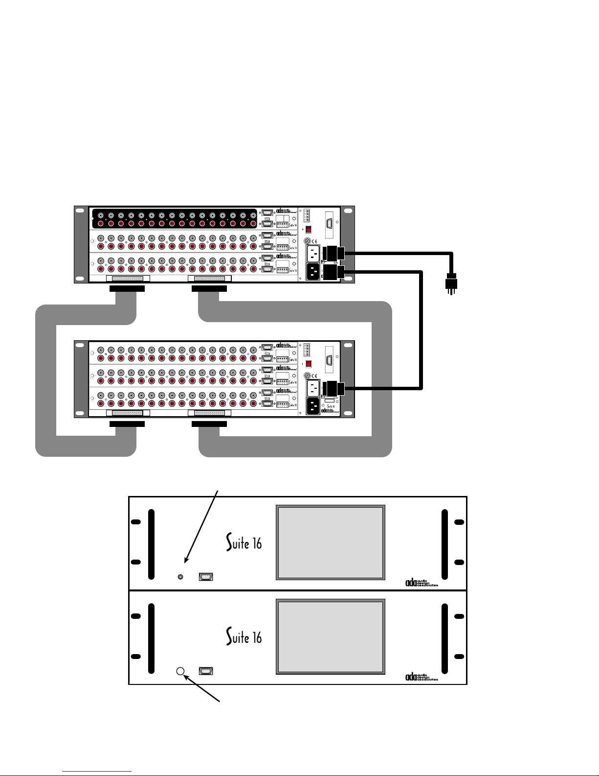
AVP-16 Slave-Unit Setup
When connecting more than one AVP-16 chassis together, the first chassis is considered the
Main Unit and all other chassis are considered Slave Units. The importance here is that the
Main Unit will become the one unit with a master turn-on switch. It will also be the chassis to
house the A-16 module. Note, that audio is passed to Slave units via two 50 pin ribbon cables
(Ribbon-50). Also, the Slave Unit will derive power from the Main Units switched AC outlet
using an IEC Female to IEC Male AC cord (IEC-MF). If additional AVP-16 Slave Units were
employed, these would connect in line to the previous Slave Units switched AC outlet. Also,
the Ribbon-50 cables would have additional connectors on the cable to permit connection of
the other Slave Units.
1
2 3 4 5 6 7 8 9 10 11 12 13 14 15 16
L
R
1
2 3 4 5 6 7 8 9 10 11 12 13 14 15 16
L
R
1
2 3 4 5 6 7 8 9 10 11 12 13 14 15 16
L
R
A-16
P-16
P-16
Input Triggers
In 1-8
A-16 • Audio Input Module
Balanced
Trigger
In 7/15
In 8/16
In 6/14
Audio Page
5-24V
Gnd
In 5/13
Input (600Ω)
AC•DC
In 1/9
In 4/12
1
2
In 3/11
In 2/10
(+)3(-)4(+)5(-)
Com
In 9-16
+12VDC Outputs
Paging Input/Trigger
Zones 1- 6 & 7-12
Zones 1-6
P-16 • Preamplifier Module
Zones 13-16
TO PTM-1225/1260
In 6/12
Gnd
In 5/11
+12VDC Output
In 1/7
In 4/10
Gnd
In 2/8
In 3/9
(-)13(+)14(+)15(+)16(+)
Zones 7-12
+12VDC Outputs
Zones 1- 6 & 7-12
Zones 1-6
P-16 • Preamplifier Module
Zones 13-16
TO PTM-1225/1260
In 6/12
Gnd
In 5/11
+12VDC Output
In 1/7
In 4/10
Gnd
In 2/8
In 3/9
(-)13(+)14(+)15(+)16(+)
Zones 7-12
+12VDC Outputs
Network Control I/O
1 Gnd
2 Fdbk
3 Cntrl
4 +V
ADA Bus®
230V
115 V
115V
1/2 ASB
115V~
WARNING! Risk Of Hazardous Energy!
Make Proper Connections.
1/4 ASB
AVERTISSEMENT! Energie Electrique
Dangereuse!
230V~
Faire Des Connexions Propres
Pour L'Hautparleur.
Voir La Notice De Fonctionnement.
CAUTION: Disconnect Supply
Switch
Cord Before Servicing.
ATTENTION: Debrancher
AC
Avant Le Depannage.
(10A)
115V~/60Hz • 230V~/50Hz
500 WATTS MAX
CAUTION
RISK OF ELECTRIC SHOCK
DO NOT OPEN
ATTENTION!
RISQUE DE CHOC ELECTRIQUE.
NE PAS OUVRIR
MADE IN U.S.A.
Main
AC
Input
AVP-16 MR Controller
SWITCHED
STANDARD
IEC TO MALE AC CORD
MAIN AC
1
2 3 4 5 6 7 8 9 10 11 12 13 14 15 16
L
R
1
2 3 4 5 6 7 8 9 10 11 12 13 14 15 16
L
R
1
2 3 4 5 6 7 8 9 10 11 12 13 14 15 16
L
R
MASTER UNIT
SLAVE UNIT
Zones 1- 6 & 7-12
Zones 1-6
P-16 • Preamplifier Module
Zones 13-16
TO PTM-1225/1260
In 6/12
Gnd
In 5/11
+12VDC Output
In 1/7
In 4/10
P-16
P-16
P-16
Gnd
In 2/8
In 3/9
(-)13(+)14(+)15(+)16(+)
Zones 7-12
+12VDC Outputs
Zones 1- 6 & 7-12
Zones 1-6
P-16 • Preamplifier Module
Zones 13-16
TO PTM-1225/1260
In 6/12
Gnd
In 5/11
+12VDC Output
In 1/7
In 4/10
Gnd
In 2/8
In 3/9
(-)13(+)14(+)15(+)16(+)
Zones 7-12
+12VDC Outputs
Zones 1- 6 & 7-12
Zones 1-6
P-16 • Preamplifier Module
Zones 13-16
TO PTM-1225/1260
In 6/12
Gnd
In 5/11
+12VDC Output
In 1/7
In 4/10
Gnd
In 2/8
In 3/9
(-)13(+)14(+)15(+)16(+)
Zones 7-12
+12VDC Outputs
MAIN AC SWITCH FOR BOTH AVP-16's
POWER RS-232
AVP-16
Network Control I/O
1 Gnd
2 Fdbk
3 Cntrl
4 +V
ADA Bus®
230V
115 V
115V
1/2 ASB
115V~
WARNING! Risk Of Hazardous Energy!
Make Proper Connections.
1/4 ASB
AVERTISSEMENT! Energie Electrique
Dangereuse!
230V~
Faire Des Connexions Propres
Pour L'Hautparleur.
Voir La Notice De Fonctionnement.
CAUTION: Disconnect Supply
Switch
Cord Before Servicing.
ATTENTION: Debrancher
AC
Avant Le Depannage.
(10A)
115V~/60Hz • 230V~/50Hz
500 WATTS MAX
CAUTION
RISK OF ELECTRIC SHOCK
DO NOT OPEN
ATTENTION!
RISQUE DE CHOC ELECTRIQUE.
NE PAS OUVRIR
MADE IN U.S.A.
Main
AC
Input
AVP-16 MR Controller
IEC MALE TO
FEMALE AC CORD
(ADA#: IEC-MF)
UNSWITCHED
50 PIN RIBBON CABLES
TWO NEEDED
(ADA#: RIBBON-50)
POWER RS-232
AVP-16
SLAVE UNIT'S POWER SWITCH IS REMOVED
& REPLACED WITH COVER PLUG
- 26 -
Page 28
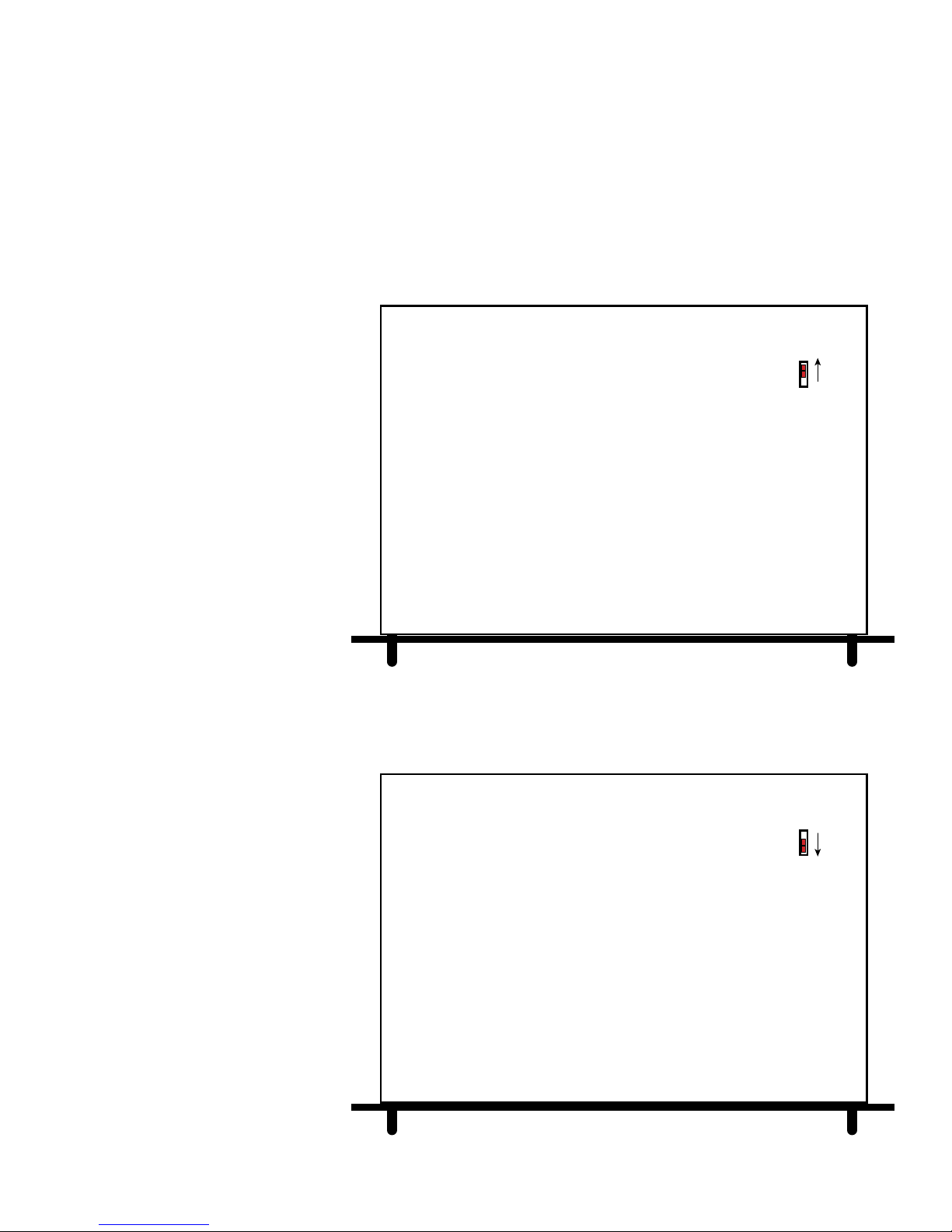
AVP-16 Main & Slave Unit Power-On Setup
During initial power up sequencing of multiple AVP-16s, it is important that all chassis initialize
together in one step. That is why the system needs to have the AC wired were the first Slave
Unit is plugged into the switched AC outlet of the Main Unit and all subsequent Slave Units
derive power from the previous Slave Unit’s switched AC outlet. For this reason, ADA will also
remove the front panel power button from all Slave Units preventing accidental power sequencing events from ever occurring. As such, Slave Units will have a cover cap in place of
the front panel power button.
In order to make certain
that the Slave Units sequence power properly,
in addition to the appropriate AC wiring and removal of the front panel
power switch (on Slave
Units), a special switch,
located on the bottom of
all AVP-16 chassis,
needs to be set in the
correct position.
AVP-16 BOTTOM
(MASTER & SLAVE UNITS
OTHER THAN LAST SLAVE)
ON/OFF BY
MASTER AVP-16
POWER SWITCH
SET MASTER &
ANY SLAVE UNITS
OTHER THAN LAST
SLAVE UNIT
The Master Unit needs
to have the switch set
toward the back of the
chassis as in the top illustration.
The last Slave Unit
needs to have its switch
set to the position toward the front of the
AVP-16 chassis.
In the case of multiple
Slave Units, those slave
units other than the last
Slave Unit, need to be
set identical to the Master Unit.
Again, only the final
Slave Unit is set to the
position as shown in the
diagram at the bottom.
ON/OFF BY
MASTER AVP-16
POWER SWITCH
SET LAST
SLAVE UNIT
AVP-16 BOTTOM
(LAST SLAVE UNIT)
- 27 -
Page 29
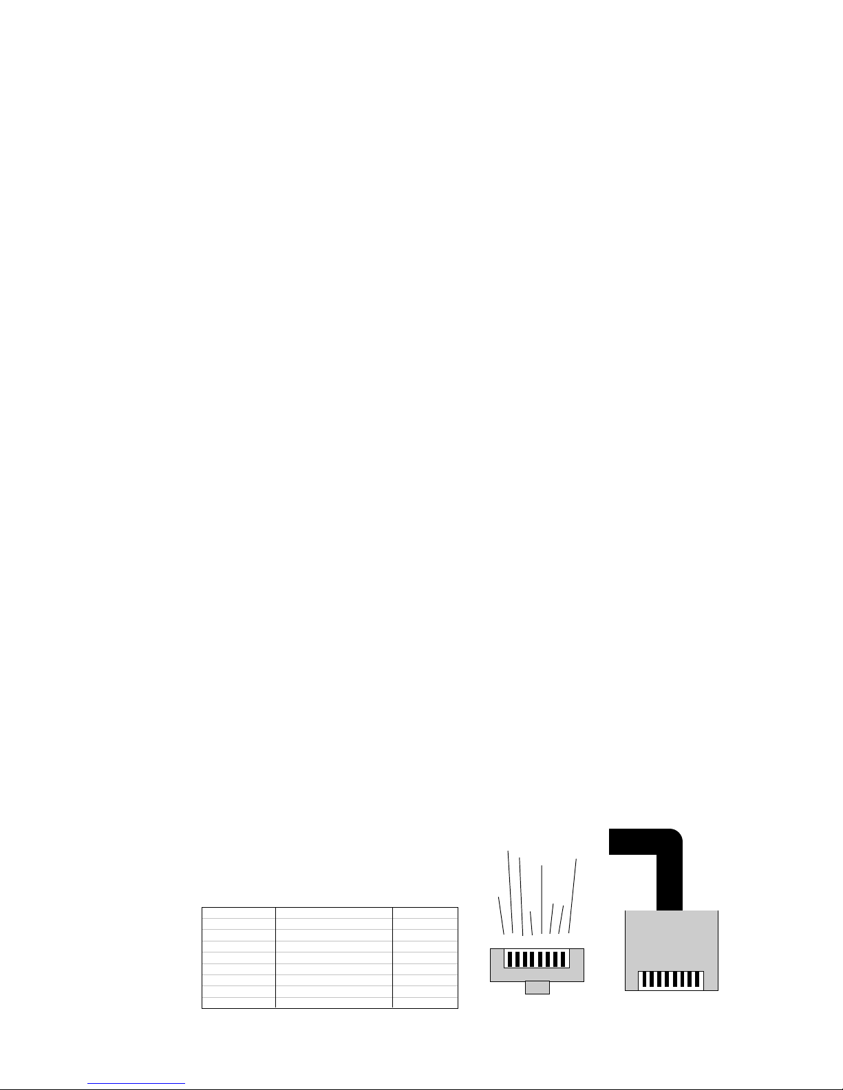
AVP-16 ADA Bus & Control Wiring
Suite 16 without other ADA components or Keypads
If you are controlling just an ADA Suite 16 from a non-ADA control interface (i.e. touch screen
control system), you can connect directly to the Suite-16’s rear panel RS-232 jack. Please
note, that the front panel and rear panel jacks are in parallel and as such, only one can be
used at any one time. Thus, if you use the rear panel connection for the control system, the
front panel connection will not operate in the event you wish to use your PC and the Suite-16
Setup software.
Suite 16 with other ADA Bus Components (i.e. Trinity Tuner) but no ADA Keypads.
If you are using other ADA Bus Components, such as the Trinity Triple Tuner or a Cinema
Rhapsody (or Reference) Home Theater Preamplifier, yet still only using a non-ADA control
system, you will most likely want to network the ADA Bus components on the ADA Bus. By
using a WH-2000 Wiring Harness and an ISO-232 ADA Bus to RS-232, you can connect the
Suite-16 and other devices directly to the WH-2000 along with the ISO-232. By using the
ISO-232 as your RS-232 interface, you can now communicate to all ADA Bus Components
through a single control system I/O. Furthermore, you free up the Suite-16’s RS-232 port
(either front or rear panel but never both at the same time) for connection to PC for programming using the Suite-16 Setup software.
ADA Bus Wiring Connection
ADA Bus wire by specification is a three conductor 18 gauge tin-coated copper wire with an
overall braided shield that is 90% braid. These connections are shown in the heavy black
lines in the diagram to the right. In the event ADA Bus wire is not available, you can use a four
conductor 16 gauge speaker cable. Please note, that ADA Bus connections are intended
strictly for short runs, to connect ADA Bus components to the WH-2000 Wiring Harness.
Because Suite-16 runs at a baud rate of 19200, long runs of this cable will cause inter-component communication to fail. To maintain the best operation at the faster baud rate of 19200,
ADA recommends limiting ADA Bus wiring to a total of 15 feet in length (that is the total
distance of all ADA Bus runs). As ADA Bus components are typically in the rack with the
Suite-16, several short ADA Bus connectors, 2 feet in length, are usually employed.
Suite-16 with ADA Controls
When using ADA Keypads including the MC-5011, MC-5000, MC-3000, MC-3800, MC-3000
OD or MC-3800 OD, you will need to wire them with a Cat. 5 cable and RJ-45 connectors at
both ends. Standard Cat. 5 cable can be used in runs up
to 700 feet in length per run. Clean termination of the RJ45 jack is essential as this wire carries both control and
feedback in addition to voltage. A short in this wire can
disrupt control and even damage both keypads and mainframe components. Tone out all terminations prior to connection. In the
event a Cat. 5
cable is damaged,
see alternate wiring options on the
next page.
PIN NUMBER COLOR FUNCTION
PIN 1 BROWN +20V
PIN 2 BROWN/WHITE GND
PIN 3 GREEN/WHITE TXPIN 4 ORANGE RX+
PIN 5 ORANGE/WHITE RXPIN 6 GREEN TX+
PIN 7 BLUE +20V
PIN 8 BLUE/WHITE GND
RJ-45 Cat. 5 Cable Connector
O
G
B
B
R
R
L
L
A
E
U
U
N
E
E
E
G
N
W
E
H
W
I
H
T
I
E
T
E
8 7 6 5 4 3 2 1
Front
B
B
G
O
R
R
R
R
O
O
E
A
W
W
E
N
N
N
N
G
E
W
W
H
H
I
I
T
T
E
E
Top
- 28 -
Page 30
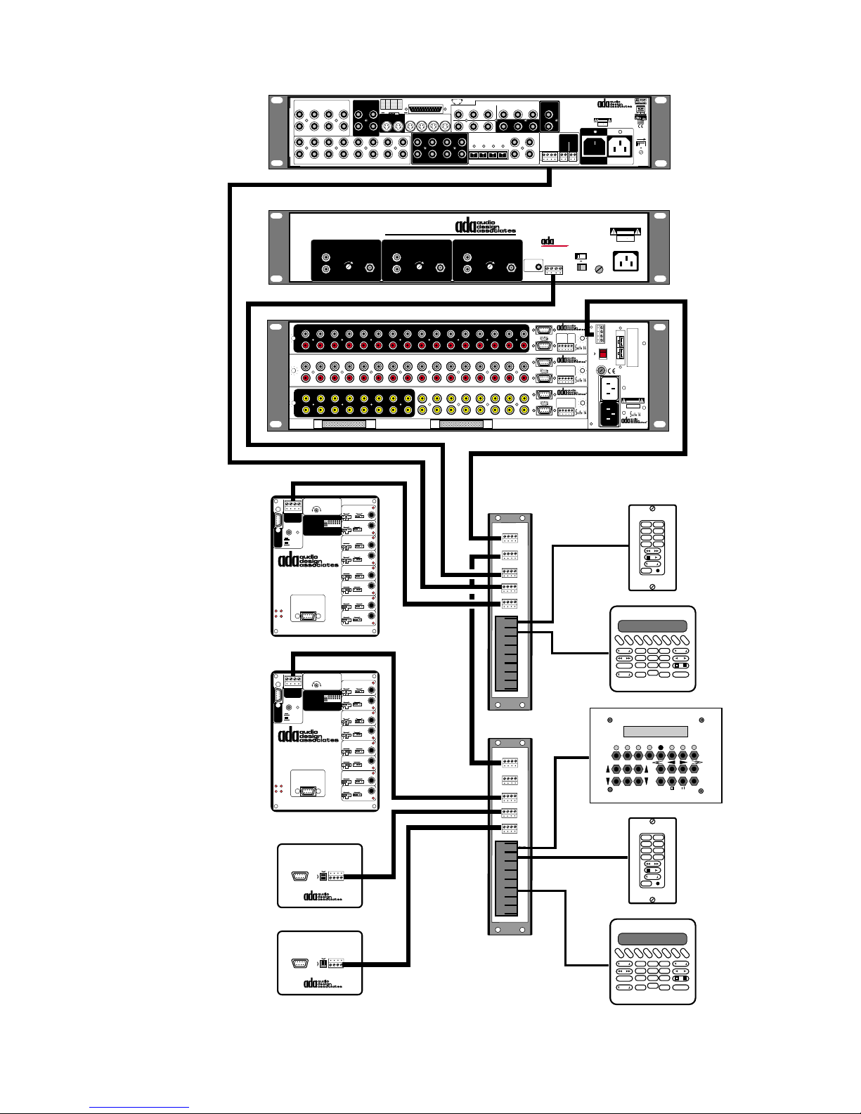
1
2
L
1
R
VIDEO INPUTS
3
4
2
5
6
LRL
3
AUDIO INPUTS
Cinema Rhapsody Mach II
PIN +/-CHAN PIN +/- CHAN
1 / 14 LT 7 / 20 SBL
2 / 15 CT 8 / 21 SBR
VIDEO OUT
7
1
8
2
4
5
8 CHANNEL DB-25 INPUT
3 / 16 RT 9 /10/22 SHLD
4 / 17 SB 11 / 23 R.T.A
5 / 18 SL 12 / 24 R.T.B
REC
6 / 19 SR 13 / 25 R.T.C
MULTI-PIN LFE SUM
0dB
+10dB
S-VIDEO INPUTS
MAIN 2341
REC
OSD
R
6
L
78
R
SBL LS
113
PIN
2514
COMPONENT VIDEO
POINTS
Y
1
2
L
MAIN
R
RS
SUBSBR
C
P
B/B-YPR/R-Y
DIGITAL AUDIO
OPTICAL INPUTS
123
INPUTS
Y
P
B/B-YPR/R-Y
3
O
UTPUT
B
P
Y
P
123
4
ADA NET“
RECORD
OUT
L
R
R
DATA PORT
Serial Data
ADA Bus¤
1 2 3 4
4
G
ND
O
UT
I
N
12
V
DC
"Dolby", "Pro Logic", & the double-D
Symbol are trademarks of Dolby
Laboratories. All rights reserved.
Manufactured under license from Digital
Theater Systems, Inc. US Pat. No.
5,451,942, 5,956,764, 5,974,380,
5,978,762 and other worldwide patents
issued and pending. "DTS", "DTS-ES
Extended Surround", and "Neo 6" are
trademarks of Digital Theater Systems,
Inc. ' 1996, 2000 Digital Theater
Systems, Inc. All rights reserved.
Manufactured under license from
12VDC OUT
100mA Max Per
DC 1
DC 2
1- 2+
1- 2+
Lucasfilm Ltd. U.S. patent numbers
5,043,970; 5,189,703; and/or 5,222,059.
European patent number 0323830.
Other U.S. and foreign patents pending.
Lucasfilm and THX are trademarks or
registered trademarks of Lucasfilm Ltd.
Surround EX is a jointly developed
technology of THX and Dolby
Laboratories, Inc., and is a trademark of
Dolby. Used under authorization.
AC OUTPUT
10A~ Max Switched
C
INEMA RHAPSODY MACH
H
OME THEATER CONTROLLER
WARNING! Risk Of Hazardous Energy! Make Proper
Connections.
CAUTION
AVERTISSEMENT! Energie Electrique Dangereuse!
RISK OF ELECTRIC SHOCK
DO NOT OPEN
Faire Des Connexions Propres Pour L’Hautparleur.
Voir La Notice De Fonctionnement.
ATTENTION!
CAUTION: Disconnect Supply Cord Before
RISQUE DE CHOC ELECTRIQUE.
NE PAS OUVRIR
Servicing.
MADE IN U.S.A.
ATTENTION: Debrancher Avant Le Depannage.
AC INPUT
115V~60Hz/230V~50Hz
II
Voltage
Selector &
Safety Fuse
On This Side
115 V
115V 230V
Use Same
Value Fuse
115V~1AS.B.
230V~.5AS.B.
To Any
Open
IRL-5000
Set to Address 1
For Sources 1-8
IRL-5000
Set to Address 2
For Sources 9-16
To RS-232 Control
System or AMX or
Crestron Control System
To Aquarius Hard-Drive
CD Library or Escient
Tunebase Pro MK III
ADA Bus to RS-232 Converter
This device complies with Part 15 of the FCC Rules.
Operation is subject to the following two conditions:
1 This device may not cause harmful interference.
2 This device must accept any interference
received, including interference that may cause
undesired operation.
TUNER 1
AUDIO OUTPUT
L
R
OUTPUT
LEVEL
1
2 3 4 5 6 7 8 9 10 11 12 13 14 15 16
L
R
1
2 3 4 5 6 7 8 9 10 11 12 13 14 15 16
L
R
13579111315
2 4 6 8 10 12 14 16
40KHz IR Repeat
1 2 3 4
Gnd Rx Tx +15V
ADA Bus¤
Data/Carrier
ADA/232
IR Flasher=Remove Jumper
Serial Direct=Insert Jumper
RS-232
Pins
RS-232
2=Tx
3=Rx
ADA Bus
5=Com
IRL-5000
Source Controller
Power On/Off IR Macro
Connect To Mainframe
Source DC Triggers &
PGM DEL
ACC-48 AC Controllers
CON ERR
40KHz IR Repeat
1 2 3 4
Gnd Rx Tx +15V
ADA Bus¤
Data/Carrier
ADA/232
IR Flasher=Remove Jumper
Serial Direct=Insert Jumper
RS-232
Pins
RS-232
2=Tx
3=Rx
ADA Bus
5=Com
IRL-5000
Source Controller
Power On/Off IR Macro
Connect To Mainframe
Source DC Triggers &
PGM DEL
ACC-48 AC Controllers
CON ERR
RS-232
RS-232
IR Repeating Only
IR Repeating Only
ISO-232
Normal
Reverse
(TuneBase)
ISO-232
Normal
Reverse
(TuneBase)
Frequency
12345678Source Ports:
Frequency
12345678Source Ports:
ADA BUS
1 2 3 4
ADA BUS
1 2 3 4
Repeater
IR - Serial
Repeater
IR - Serial
Repeater
IR - Serial
Repeater
IR - Serial
Repeater
IR - Serial
Repeater
IR - Serial
Repeater
IR - Serial
Repeater
IR - Serial
Repeater
IR - Serial
Repeater
IR - Serial
Repeater
IR - Serial
Repeater
IR - Serial
Repeater
IR - Serial
Repeater
IR - Serial
Repeater
IR - Serial
Repeater
IR - Serial
VIDEO INPUTS
Data Only
Norm Invert
Off
Serial
Data Only
Norm Invert
Off
Data Only
Norm Invert
Off
Serial
Data Only
Norm Invert
Off
Data Only
Norm Invert
Off
Serial
Data Only
Norm Invert
Off
Data Only
Norm Invert
Off
Serial
Data Only
Norm Invert
Off
Data Only
Norm Invert
Off
Serial
Data Only
Norm Invert
Off
Data Only
Norm Invert
Off
Serial
Data Only
Norm Invert
Off
Data Only
Norm Invert
Off
Serial
Data Only
Norm Invert
Off
Data Only
Norm Invert
Off
Serial
Data Only
Norm Invert
Off
ISO-232
Serial
Serial
Serial
Serial
Serial
Serial
Serial
Serial
ANTENNA
1
2
3
4
5
6
7
8
1
2
3
4
5
6
7
8
Trinity Triple Tuner
T
RINITY TRIPLE TUNER
AUDIO OUTPUT
TUNER 2
L
R
OUTPUT
LEVEL
ANTENNA
AUDIO OUTPUT
A-16
P-16
13579111315
V-16
2 4 6 8 10 12 14 16
EXPANSION PORTS
ADA Bus
To Any
Open
WH-2000
ADA Bus
Jumper
J2 to J1
ADA Bus
To Any
Open
TUNER 3
L
ANTENNA
IR Flasher
OUTPUT
LEVEL
Input
Input Triggers
In 1-8
In 6/14
In 5/13
In 4/12
In 3/11
In 9-16
+12VDC Outputs
Zones 1- 6 & 7-12
Zones 1-6
In 6/12
In 5/11
In 4/10
In 3/9
Zones 7-12
+12VDC Outputs
Output Triggers
Out 1-8
Out 7/15
Out 6/14
Out 5/13
Out 4/12
Out 3/11
Out 9-16
+12VDC Outputs
R
ADA Bus to WH-2000 J1
WH-2000
1 2 3 4
J1
J2
J3
J4
J5
RJ45
RJ45
RJ45
RJ45
RJ45
RJ45
RJ45
RJ45
WH-2000
1 2 3 4
J1
J2
J3
J4
J5
RJ45
RJ45
RJ45
RJ45
RJ45
RJ45
RJ45
RJ45
WH-2000
WH-2000
Wire Harness
BUS
• ICC - I
NTERACTIVE COMPONENT COMMUNICATION
The Trinity Does Not
Require a BI-3000.
ADA Bus™
1 2 3 4
In 7/15
In 8/16
Gnd
In 1/9
In 2/10
Paging Input/Trigger
TO PTM-1225/1260
Gnd
In 1/7
In 2/8
Out 8/16
Gnd
Out 1/9
Out 2/10
®
•
115 V
115V 230V
Voltage Selector
A-16 • Audio Input Module
Balanced
Trigger
Audio Page
5-24V
Input (600‰)
AC¥DC
2
1
(+)3(-)4(+)5(-)
Com
P-16 • Preamplifier Module
Zones 13-16
+12VDC Output
Gnd
(-)13(+)14(+)15(+)16(+)
V-16 • Video I/O Module
Programmed Video
Input Triggers
5-24V AC¥DC
Gnd
(-)1(+)2(+)3(+)4(+)
Input Triggers
Cat. 5
To Any
Open
Cat. 5
To Any
Open
CAUTION: DISCONNECT SUPPLY
CORD BEFORE SERVICING.
ATTENTION: DEBRANCHER AVANT
LE DEPANNAGE.
CAUTION
RISK OF ELECTRIC SHOCK
DO NOT OPEN
ATTENTION!
RISQUE DE CHOC ELECTRIQUE.
NE PAS OUVRIR
MADE IN U.S.A.
AC INPUT
115V 2/10A S.B.
230V 1/10 AS.B.
115 V
Network Control I/O
1 Gnd
2 Fdbk
3 Cntrl
4 +V
ADA Bus¤
230V
115 V
115V
1/2 ASB
115V~
WARNING! Risk Of Hazardous Energy!
Make Proper Connections.
1/4 ASB
AVERTISSEMENT! Energie Electrique
230V~
Faire Des Connexions Propres
Pour L’Hautparleur.
Voir La Notice De Fonctionnement.
CAUTION: Disconnect Supply
Switch
Cord Before Servicing.
ATTENTION: Debrancher
AC
Avant Le Depannage.
(10A)
115V~/60Hz ¥ 230V~/50Hz
500 WATTS MAX
CAUTION
RISK OF ELECTRIC SHOCK
DO NOT OPEN
ATTENTION!
RISQUE DE CHOC ELECTRIQUE.
NE PAS OUVRIR
MADE IN U.S.A.
Main
AC
Input
AVP-16 MR Controller
FF
BASS
EXTRA
VOL
FM 1 FM 2 AM CD 1 CD 2 DSS DVD AUX
VOL
PTY 1 PTY 2
FF
BASS
EXTRA
VOL
Dangereuse!
OFF
123
456
789
*
OFF
123
456
789
*
VOL
0
VOL
0
FM2FM1
CD1AM
DSSCD2
AUXDVD
ENT
SHIFT
FM2FM1
CD1AM
DSSCD2
AUXDVD
ENT
MC-5011
TREB
OFF
OFF
MC-5011
TREB
OFF
MC-5000
MC-3000 OD
MC-5000
- 29 -
Page 31
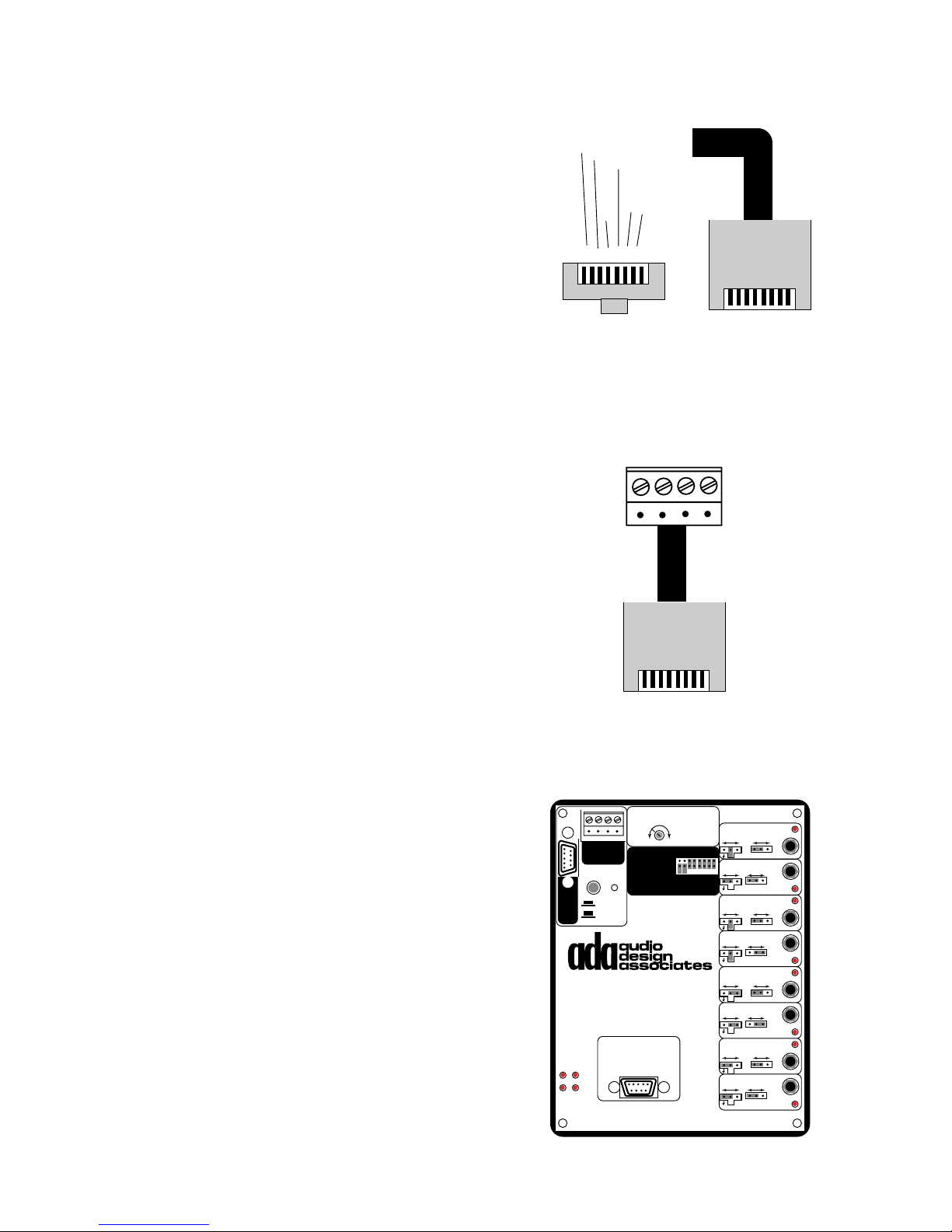
Damaged Wiring Options
In the event that a Cat. 5 cable is damaged, you can still
get an MC-5000, MC-5011, MC-3000, MC-3800, MC-3000
OD, or MC-3800 OD to operate, providing that six of the
eight Cat. 5 wires are good. To do so, eliminate the first
wire and the eighth wire from the RJ-45 connector, at both
RJ-45 Cat. 5 Cable Connector
O
B
G
O
G
B
R
R
R
R
R
L
E
U
E
E
N
O
A
E
A
W
N
E
N
N
G
N
G
E
E
W
W
H
W
H
I
H
I
T
I
T
E
T
E
E
the wire harness and keypad termination point. Please
note, you cannot re-wire an MC-6000 (Keypad with Video
8 7 6 5 4 3 2 1
Display) in this manner. The above keypads wired in this
fashion will work as all other keypads.
Front
Top
CAT-Link and ADA Bus Wiring
In some cases, you may end up upgrading a project previously wired with ADA Bus four
conductor wiring. As all Suite 16 keypads have only RJ-45 Cat
Link termination, you will require the BUS-CAT Module per keypad. This in-line ADA Bus screw terminal connection to male RJ45 jack will permit the keypads to connect to the system. Here
ADA suggests using the WH-3000 Wiring Harness (all ADA Bus
jacks) to terminate the ADA Bus keypad wiring at the mainframe,
while the keypads themselves terminate with RJ-45. In this situation, you will need to run the Suite 16 System at a baud rate of
1200 because the ADA Bus wire to the keypad location is not fast
enough for the optimal system baud rate of 19200. When running
the Suite 16 System at 1200, the initial (when the power switch on
the Suite 16 is first turned on) power up sequence will take slightly
longer. Also, at 1200 baud, using more than two Aquarius outputs
will most likely slow system operation down some. Otherwise,
most system features will work without incidence.
+15V Tx Rx Gnd
4 3 2 1
ADA Bus
RJ-45
Top
IR Repeating
Whether you are running a Suite 16 System at 1200 baud
or the standard 19200 baud, the IR receivers mounted in
the MC-5000, MC-5011, MC-3000 and MC-3800 can IR
repeat to source components via the IRL-5000. This will
permit you to use the original source remote control from a
remote room location. Please note, that while most source
components operate at 40KHz, some do not and as such,
will not IR repeat through the IRL-5000. The IRL-5000 has
a trim pot adjustment for the IR carrier frequency which is
only used to fine-tune IR repeating. Also, in order to employ IR repeating, the keypad’s IR needs to be active. On
the MC-5011, this requires that the jumper pin on the circuit board be in place. On the other keypads, the IR receiver is turned on and off via on-keypad programming.
Also, the ports on the IRL-5000 need to have their jumper
pins set so that IR repeating is active.
- 30 -
1 2 3 4
Gnd Rx Tx +15V
ADA Bus®
ADA/232
RS-232
Pins
RS-232
2=Tx
3=Rx
ADA Bus
5=Com
IRL-5000
Source Controller
Power On/Off IR Macro
Connect To Mainframe
PGM DEL
CON ERR
Source DC Triggers &
ACC-48 AC Controllers
IR Repeating Only
40KHz IR Repeat
Frequency
Data/Carrier
IR Flasher=Remove Jumper
12345678Source Ports:
Serial Direct=Insert Jumper
Repeater
IR - Serial
Repeater
IR - Serial
Repeater
IR - Serial
Repeater
IR - Serial
Repeater
IR - Serial
Repeater
IR - Serial
Repeater
IR - Serial
Repeater
IR - Serial
Off
Off
Off
Off
Off
Off
Off
Off
Serial
Data Only
Norm Invert
Serial
Data Only
Norm Invert
Serial
Data Only
Norm Invert
Serial
Data Only
Norm Invert
Serial
Data Only
Norm Invert
Serial
Data Only
Norm Invert
Serial
Data Only
Norm Invert
Serial
Data Only
Norm Invert
1
2
3
4
5
6
7
8
Page 32
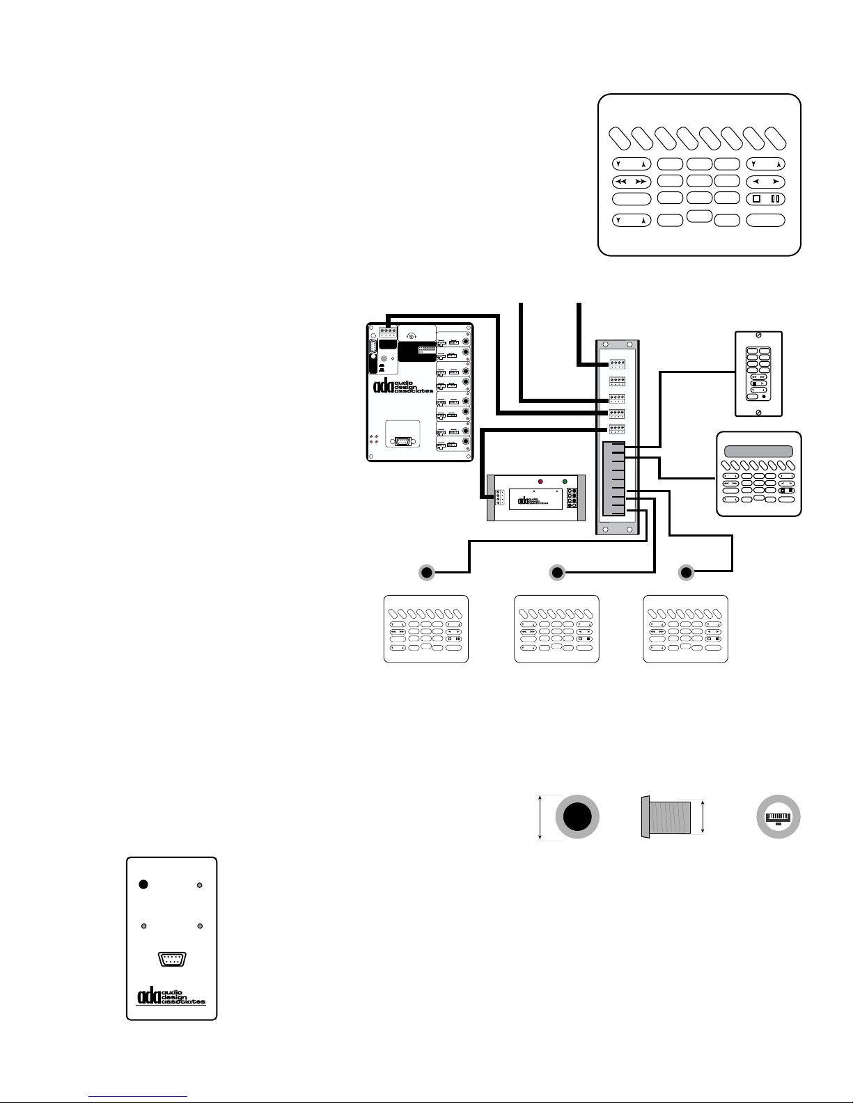
IR Control of the Suite 16
Front
1.264" .99"
Side Back
RJ-45
Female
ADA provides the RC-40 hand-held IR Remote Control for wireless infrared control of the Suite-16 and source components.
This unit features the same button layout as an MC-5000 and
like any system keypad, the RC-40 is programmed for a specific room. As such, it cannot be taken from one room to the
next. If this is done, the RC-40 will still control the room it is
programmed for. The RC-40 issues commands at 1200 baud
(IR cannot be passed at 19200 baud) and can be aimed at an
IRR-5000 or any ADA keypad (providing that
its IR receivers is active).
To
Trinity
Suite-16
To
F
M
1
BASS
EXTRA
VOL
F
C
A
M
M
2
1
4
789
*
C
D
D
D
D
1
2
3
2
6
5
0
ENT
A
S
V
U
S
D
X
TREB
OFF
For systems set to run at the
optimal factory baud rate setting of 19,200, you will need to
include a single BRT-1 Baud
Rate Translator in the system.
The BRT-1 is connected to any
open ADA Bus jack on either
the WH-2000 or WH-6000. IR
commands issued by the RC40 are up-converted to 19200
1 2 3 4
Gnd Rx Tx +15V
ADA BusÆ
ADA/232
RS-232
Pins
RS-232
2=Tx
3=Rx
ADA Bus
5=Com
IRL-5000
Source Controller
Power On/Off IR Macro
Connect To Mainframe
Source DC Triggers &
PGM DEL
ACC-48 AC Controllers
CON ERR
IRL-5000
IR Repeating Only
40KHz IR Repeat
Frequency
12345678Source Ports:
Data/Carrier
IR Flasher=Remove Jumper
Serial Direct=Insert Jumper
1
Repeater
Serial
IR - Serial
Data Only
Norm Invert
Off
Repeater
Serial
IR - Serial
Data Only
Norm Invert
Off
2
3
Repeater
Serial
IR - Serial
Data Only
Norm Invert
Off
Repeater
Serial
IR - Serial
Data Only
Norm Invert
Off
4
5
Repeater
Serial
IR - Serial
Data Only
Norm Invert
Off
Repeater
Serial
IR - Serial
Data Only
Norm Invert
Off
6
7
Repeater
Serial
IR - Serial
Data Only
Norm Invert
Off
Repeater
Serial
IR - Serial
Data Only
Norm Invert
Off
8
BRT-1
ADA Bus
Translation
4 +VDC
In Process
3 Data
2 Data
DIP Switches
1 GND
Do Not Matter
Baud Rate Translator (1200 to 19200)
BRT-1
Power
WH-2000
1 2 3 4
J1
J2
J3
J4
J5
RJ45
RJ45
RJ45
RJ45
RJ45
RJ45
RJ45
RJ45
WH-2000
Cat. 5
To Any
Open
F
M
EXTRA
F
1
BASS
VOL
A
M
M
2
123
456
789
*
FM2FM1
CD1AM
DSSCD2
DVD
AUX
VOL
OFF
C
C
D
D
A
D
D
S
V
U
D
1
2
S
X
TREB
0
ENT
OFF
by the BRT-1, so the Suite 16,
as well as any other ADA Bus
IRR-5000
IRR-5000
IRR-5000
component (Trinity Tuner), will
perform the function selected
F
F
C
C
D
D
For systems running at 1200
baud, no BRT-1 is required for
IR control. For these systems,
all ADA Bus components will
M
1
BASS
EXTRA
VOL
A
M
M
2
123
456
789
*
A
D
D
S
V
U
1
2
S
D
X
TREB
0
ENT
OFF
RC-40
Room Specific
F
F
C
C
D
D
M
1
BASS
EXTRA
VOL
A
M
M
2
123
456
789
*
A
D
D
S
V
U
1
2
S
D
X
TREB
0
ENT
OFF
RC-40
Room Specific
F
F
C
C
D
D
M
1
BASS
EXTRA
VOL
A
M
M
2
123
456
789
*
A
D
D
S
V
U
1
2
S
D
X
TREB
0
ENT
OFF
RC-40
Room Specific
need to be set to 1200 baud. ADA strongly suggests avoiding running systems at 1200 baud,
especially when using more than 32 zones and/or the Aquarius Hard Drive Jukebox, as there
will be too much bus traffic for smooth operation of the system.
ADA also provides the IRR-5000 peep-hole IR
Receiver that features an RJ-45 connector. This
receiver is ideally run to an open RJ-45 connec-
tor on the system wire harness.
The IRR-5000 can also be used
ON/O
FF
P
OWER
Turn off IRT-232
when not in use.
RS-232
T
X
for only IR repeating, if the system is running at 19200 without a BRT-1.
R
X
You can also generate IR commands for capture by other IR transmitting devices using the IRT-232. The IRT-232 connects to your PC and features an IR
IRT-232
RS-232 I
NFRARED TRANSCEIVER
Transceiver. When using the Suite 16 Tester program and an IRT-232, you
can generate most any Suite 16 command in IR form. Again, it is important to
remember that all commands are room specific and emit at 1200 baud.
- 31 -
Page 33
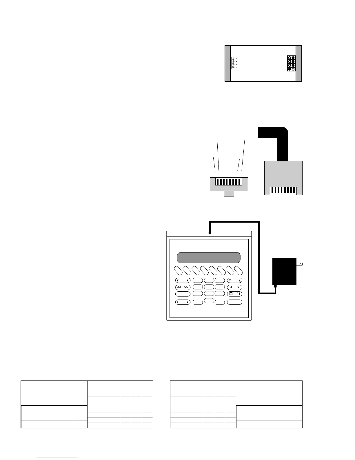
RF Control
ADA provides an RF control option for Suite 16 Systems operating at either 1200 baud or 19200 baud. This involves using a
single RFT-3000 RF Transceiver per system. The keypads that
can be controlled via RF include the MC-5000, MC-3000, MC3800, MC-3000 OD, and MC-3800 OD. The MC-5011 and MC6000 cannot be controlled via RF. Please note, while control via RF is possible, with complete
feedback, the keypads still will require power.
RFT-3000
RF control becomes an option, when wiring is damaged or
not the improper type (a two conductor cable). If the wiring to keypad locations provides only four wires, because
of damage or improper planning, then employing the RF
Control option becomes a viable option. Here, the existing
wires can be used for power only, while all communication
RJ-45 Cat. 5 Cable Connector
B
B
B
L
L
U
U
E
E
W
H
I
T
E
B
R
R
O
O
W
W
N
N
W
H
I
T
E
and feedback take place via RF. Here, in addition to the
system requiring one RFT-3000 RF Transceiver, each key-
8 7 6 5 4 3 2 1
pad will also require the RFT-MOD RF Module which is
connected to the keypad at the ADA factory.
Front
Top
Alternately, you can employ the RF Control option for rooms
where no wire can be run. In this case, instead of using an
in-wall keypad, you can use the MC-5000
Table-Top control with RFT-MOD. This keypad will ship with a power supply which can
be plugged into any AC outlet. The keypad
can be used outdoors but it is not waterproof
in any manner and should not be left outside.
Whether you use an in-wall or table-top RF
keypad, ADA suggests running your Suite 16
System at a baud rate of 19200 for optimum
performance. For the most part, function from
F
M
1
BASS
EXTRA
VOL
F
M
2
C
C
A
M
1
4
789
*
D
D
D
1
2
3
2
6
5
0
ENT
A
D
U
S
V
X
S
D
TREB
OFF
15VDC
an RF control is identical to a hard-wired control. To the end user, there is no difference.
When installing the controls, in addition to the normal setting of the controls baud rate to
match the system, you must also make certain that the RFT-3000 and RFT-MOD dip switch
settings are set to the same baud rate. Finally, you will also need to make certain that the
addresses match on the RFT-3000 and the RFT-MOD. Both the RF baud rate and address
are set using the four switch DIP switch on the RFT-3000 and RFT-MOD. Please note, that
you select one address setting per system, as these addresses have nothing to do with zones.
RFT-3000
Dip Switch Settings
(Must match RFT-MOD)
SWITCH NO. 1
19,200 BAUD UP
1,200 BAUD DN
SWITCH NO. 2 3 4
ADDRESS 1 UP UP U P
ADDRESS 2 DN U P UP
ADDRESS 3 UP DN UP
ADDRESS 4 DN DN UP
ADDRESS 5 UP UP DN
ADDRESS 6 DN U P DN
ADDRESS 7 UP DN DN
ADDRESS 8 DN DN DN
SWITCH NO. 1 2 3
ADDRESS 1 UP UP U P
ADDRESS 2 UP UP DN
ADDRESS 3 UP DN UP
ADDRESS 4 UP DN DN
ADDRESS 5 DN U P UP
ADDRESS 6 DN U P DN
ADDRESS 7 DN DN UP
ADDRESS 8 DN DN DN
Keypad RFT-MOD
Dip Switch Settings
(Must match RFT-3000)
SWITCH NO. 4
19,200 BAUD UP
1,200 BAUD DN
- 32 -
Page 34
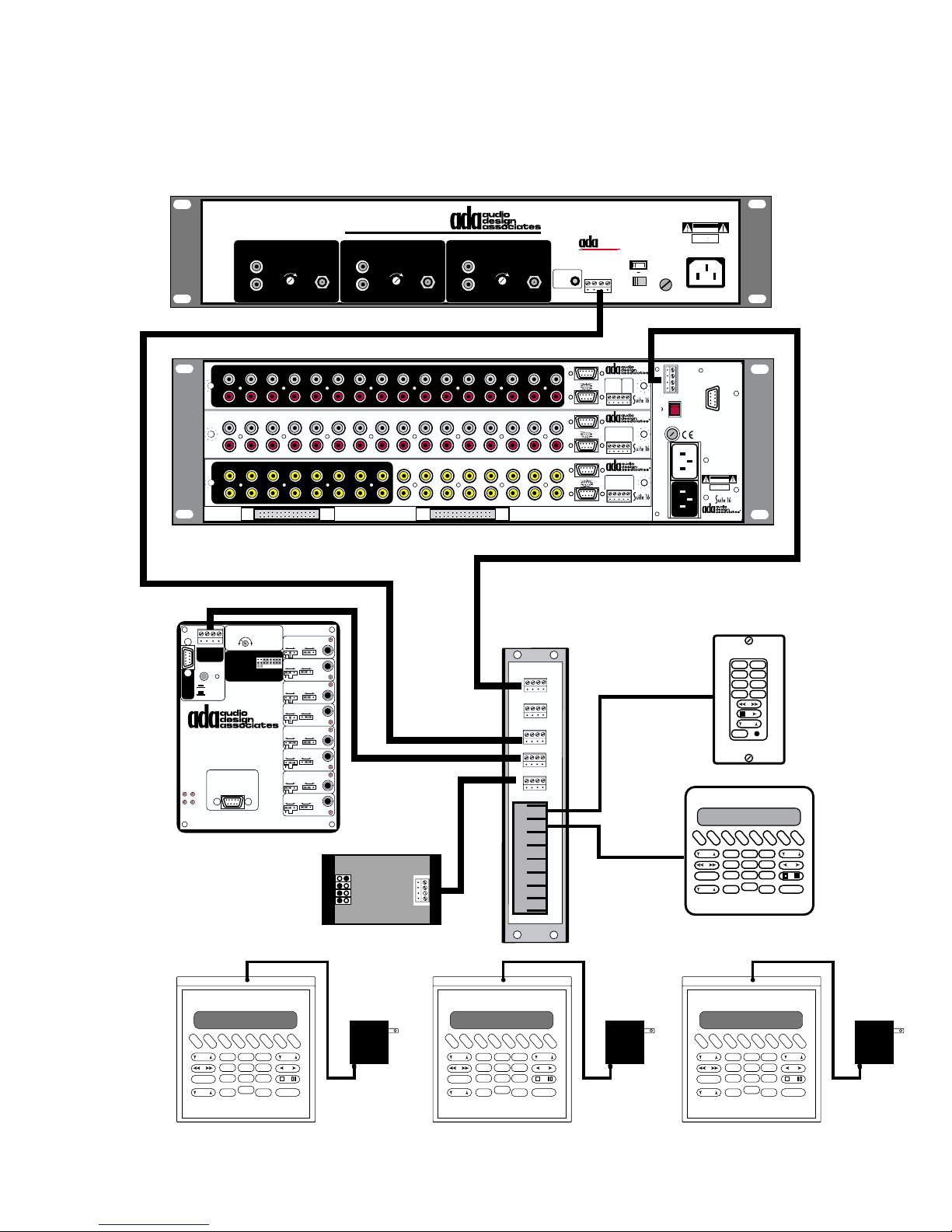
In the diagram below, you can see that it is possible to mix and match keypads that are both
hardwired, hardwired for power but running on RF for control and feedback, or completely
wireless using an AC transformer. Only one RFT-3000 is required per system.
Trinity Triple Tuner
This device complies with Part 15 of the FCC Rules.
Operation is subject to the following two conditions:
1 This device may not cause harmful interference.
2 This device must accept any interference
received, including interference that may cause
undesired operation.
TUNER 1
AUDIO OUTPUT
L
ANTENNA
R
OUTPUT
LEVEL
T
RINITY TRIPLE TUNER
TUNER 2
AUDIO OUTPUT
L
R
OUTPUT
LEVEL
ANTENNA
AUDIO OUTPUT
TUNER 3
L
R
OUTPUT
LEVEL
ANTENNA
IR Flasher
Input
BUS
• ICC - I
NTERACTIVE COMPONENT COMMUNICATION
The Trinity Does Not
Require a BI-3000.
ADA Bus™
1 2 3 4
®
•
115V 230V
Voltage Selector
CAUTION: DISCONNECT SUPPLY
CORD BEFORE SERVICING.
ATTENTION: DEBRANCHER AVANT
LE DEPANNAGE.
CAUTION
RISK OF ELECTRIC SHOCK
DO NOT OPEN
ATTENTION!
RISQUE DE CHOC ELECTRIQUE.
NE PAS OUVRIR
MADE IN U.S.A.
115V 2/10A S.B.
230V 1/10 AS.B.
AC INPUT
115 V
115 V
2 3 4 5 6 7 8 9 10 11 12 13 14 15 16
1
L
R
1
2 3 4 5 6 7 8 9 10 11 12 13 14 15 16
L
R
13579111315
2 4 6 8 10 12 14 16
VIDEO INPUTS
Video Out Room 4-6
IR Repeating Only
1 2 3 4
Gnd Rx Tx +15V
ADA BusÆ
ADA/232
RS-232
Pins
RS-232
2=Tx
3=Rx
ADA Bus
5=Com
IRL-5000
Source Controller
Power On/Off IR Macro
Connect To Mainframe
PGM DEL
ACC-48 AC Controllers
CON ERR
40KHz IR Repeat
Data/Carrier
IR Flasher=Remove Jumper
Serial Direct=Insert Jumper
Source DC Triggers &
Frequency
12345678Source Ports:
Repeater
IR - Serial
Repeater
IR - Serial
Repeater
IR - Serial
Repeater
IR - Serial
Repeater
IR - Serial
Repeater
IR - Serial
Repeater
IR - Serial
Repeater
IR - Serial
Serial
Data Only
Norm Invert
Off
Serial
Data Only
Norm Invert
Off
Serial
Data Only
Norm Invert
Off
Serial
Data Only
Norm Invert
Off
Serial
Data Only
Norm Invert
Off
Serial
Data Only
Norm Invert
Off
Serial
Data Only
Norm Invert
Off
Serial
Data Only
Norm Invert
Off
IRL-5000
A-16
P-16
V-16
EXPANSION PORTS
1
2
3
4
5
6
7
8
RFT-3000
13579111315
2 4 6 8 10 12 14
16
ADA Bus to WH-2000 J1
WH-2000
1 2 3 4
J1
J2
J3
J4
J5
RJ45
RJ45
RJ45
RJ45
RJ45
RJ45
RJ45
RJ45
WH-2000
Zones 1-6
Zones 7-12
In 9-16
Out 1-8
Out 9-16
Input Triggers
In 1-8
In 6/14
In 5/13
In 4/12
In 3/11
+12VDC Outputs
Zones 1- 6 & 7-12
In 6/12
In 5/11
In 4/10
In 3/9
+12VDC Outputs
Output Triggers
Out 6/14
Out 5/13
Out 4/12
Out 3/11
+12VDC Outputs
In 7/15
TO PTM-1225/1260
Out 7/15
In 8/16
Gnd
In 1/9
In 2/10
Gnd
In 1/7
In 2/8
Out 8/16
Gnd
Out 1/9
Out 2/10
A-16 Audio Input Module
Balanced
Trigge r
Audio Page
5-24V
Input (600 )
AC DC
1
2
(+)3(-)4(+)5(-)
Com
Paging Input/Trigger
P-16 Preamplifier Module
Zones 13-16
+12VDC Output
Gnd
(-)13(+)14(+)15(+)16(+)
V-16 Video I/O Module
Programmed Video
Input Triggers
5-24V AC DC
Gnd
4
(-)1(+)2(+)3(+)
(+)
Input Triggers
Cat. 5
To Any
Open
1/2 ASB
1/4 ASB
Switch
115V~
230V~
(10A)
Main
Input
ADA BusÆ
230V
115V
AC
AC
115 V
1 Gnd
2 Fdbk
3 Cntrl
4 +V
Network Control I/O
WARNING! Risk Of Hazardous Energy!
Make Proper Connections.
AVERTISSEMENT! Energie Electrique
Dangereuse!
Faire Des Connexions Propres
Pour L'Hautparleur.
Voir La Notice De Fonctionnement.
CAUTION: Disconnect Supply
Cord Before Servicing.
ATTENTION: Debrancher
Avant Le Depannage.
115V~/60Hz 230V~/50Hz
500 WATTS MAX
CAUTION
RISK OF ELECTRIC SHOCK
DO NOT OPEN
ATTENTION!
RISQUE DE CHOC ELECTRIQUE.
NE PAS OUVRIR
MADE IN U.S.A.
AVP-16 MR Controller
F
F
M
M
1
2
BASS
EXTRA
VOL
FM2FM1
CD1AM
DSSCD2
DVD
AUX
VOL
OFF
C
C
A
D
D
M
1
2
1
2
4
5
789
0
*
A
D
D
S
V
D
S
3
TREB
6
ENT
OFF
MC-5011
U
X
F
F
C
C
D
D
M
1
BASS
EXTRA
VOL
A
M
M
2
1
4
789
*
D
1
A
D
S
V
U
2
S
D
X
3
2
TREB
6
5
0
ENT
OFF
15VDC
F
M
1
BASS
EXTRA
F
M
2
VOL
C
C
A
D
D
M
1
2
1
2
4
5
789
0
ENT
*
- 33 -
15VDC
D
D
A
S
V
U
S
D
X
3
TREB
6
OFF
F
M
1
BASS
EXTRA
F
M
2
VOL
C
C
A
D
D
M
1
2
1
2
4
5
789
0
ENT
*
D
D
A
S
V
U
S
D
X
3
TREB
6
OFF
15VDC
MC-5000T RFMC-5000T RFMC-5000T RF
Page 35
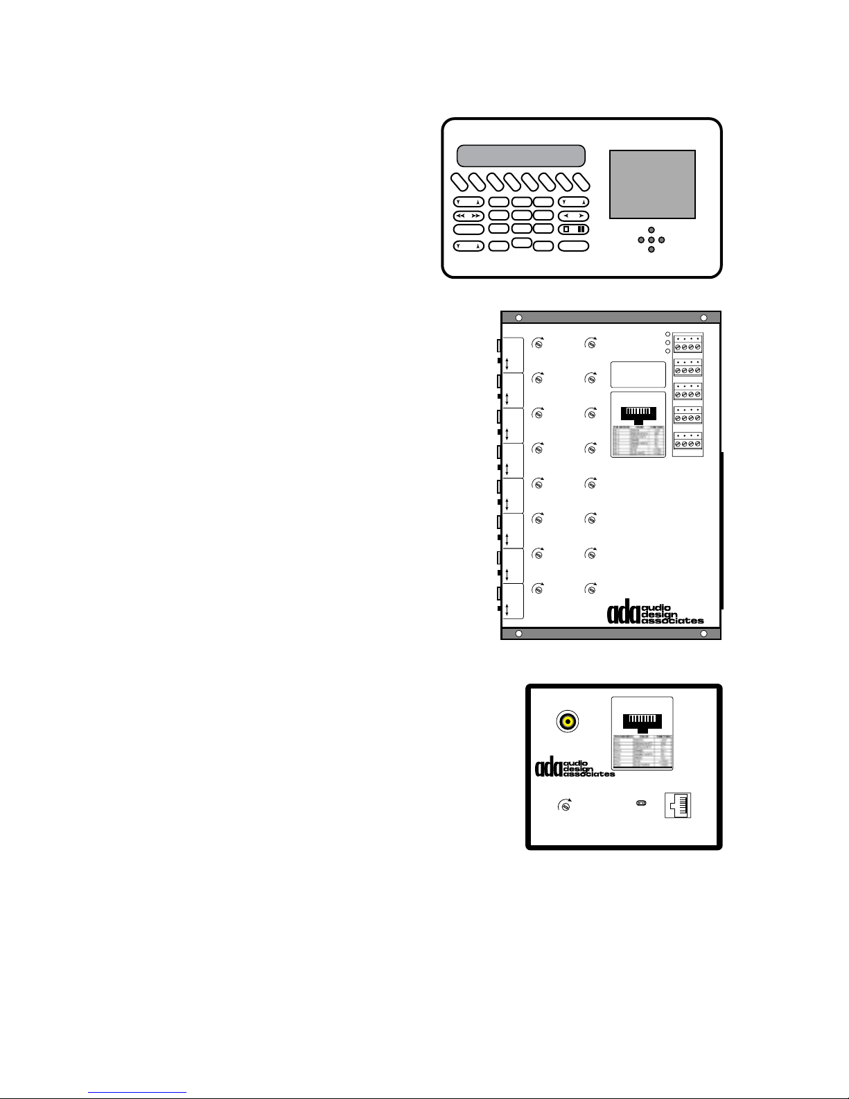
MC-6000 Keypad with Video, WH-6000, & TV-6000
The MC-6000 Keypad fits a four-gang box and in
addition to the MC-5000 Rapture Keypad, features
a small LCD preview display. There are also five
navigation buttons below the screen for up, down,
right, left, and enter (select) control. The enter button is also found on the MC-5000 numeric button
area. The IRL-5000 has the directional buttons available and much like any transport function, the
keypad’s 12 character LED display can read these
function names when pressed.
F
M
1
BASS
EXTRA
VOL
F
M
C
A
D
M
2
1
1
2
456
789
0
*
C
D
2
A
D
D
U
S
V
X
S
D
3
TREB
ENT
OFF
The MC-6000 runs on the same Cat. 5 cable that you would
use for an MC-5011, MC-5000, or MC-3000 OD. Termination is also the same. However, the MC-6000 uses these
eight wires slightly differently, since composite video is also
passed along the single Cat. 5 cable. As such, in order for
the MC-6000 to display video, you will need to use the WH6000 Wiring Harness. The WH-6000 features eight RJ-45
jacks that correspond to the eight composite video input
jacks. If an MC-6000 is connected to RJ-45 jack number
three, then the composite video output for that display must
connect to composite video input number three. Each composite video input on the WH-6000 also has a Hi-Z/75Ω
Normal switch. If you are splitting this video signal to perhaps drive two MC-6000’s on the same zone, then you will
need to set one of these switches to Hi-Z while the second
WH-6000 composite video input is set to normal.
ADA also provides the TV-6000 which is a small black box that
features an RJ-45 input and a composite video output. This
permits you to drive a video signal to a TV by running Cat. 5
cable to the TV which will be fitted with the TV-6000. Again, if a
composite video signal is “Y” split to input to two jacks on the
WH-6000, and one RJ-45 connector is running to an MC-6000
while the other is running to a TV-6000 for connection to a TV
set, then one Hi-Z/75Ω switch would be set to Hi-Z while the
other is set to 75Ω (Normal). In the event you did not run an
Cat.-5 Cable from the mainframe to the TV location but can run
a jumper Cat. 5 cable from the keypad to the TV, you can opt to
run video to the TV this way as well.
Video
In 1
Video
In 2
Video
In 3
Video
In 4
Video
In 5
Video
In 6
Video
In 7
Video
In 8
Cat-Link 1
H.F. Trim
75Ω
Hi-Z
Cat-Link 2
H.F. Trim
75Ω
Hi-Z
Cat-Link 3
H.F. Trim Gain Trim
75Ω
Hi-Z
Cat-Link 4
H.F. Trim Gain Trim
75Ω
Hi-Z
Cat-Link 5
H.F. Trim Gain Trim
75Ω
Hi-Z
Cat-Link 6
H.F. Trim Gain Trim
75Ω
Hi-Z
Cat-Link 7
H.F. Trim Gain Trim
75Ω
Hi-Z
Cat-Link 8
H.F. Trim Gain Trim
75Ω
Hi-Z
WH-6000
Video Output (75Ω)
H.F. Gain
TV-6000
Cat-Link Video Receiver
Gain Trim
Gain Trim
Pull Shunting Pin
For Hi-Z Input
Bus Power
ADA Bus
+V Tx Rx Gnd
4 3 2 1
RJ-45 Cat-Link
8 7 6 5 4 3 2 1
RJ-45 Cat-Link
8 7 6 5 4 3 2 1
Cat-Link Video Input
Tx
Rx
Cat-Link 1 Out
Cat-Link 2 Out
Cat-Link 3 Out
Cat-Link 4 Out
Cat-Link 5 Out
Cat-Link 6 Out
Cat-Link 7 Out
Cat-Link 8 Out
(From WH-6000)
In
Loop
Out
I/O 1
I/O 2
I/O 3
While the MC-5011, MC-5000, MC-3000 OD, and/or MC-3800 OD keypads can be used with
the WH-2000 or WH-6000 Wire Harness, the MC-6000 can only be used with the WH-6000
Wire Harness. When using the MC-5011, MC-5000, MC-3000 OD, and/or MC-3800 OD keypads on a WH-6000, special settings must be made in order to permit the keypads to operate
properly. See the instructions included with the WH-6000 regarding these settings.
- 34 -
Page 36
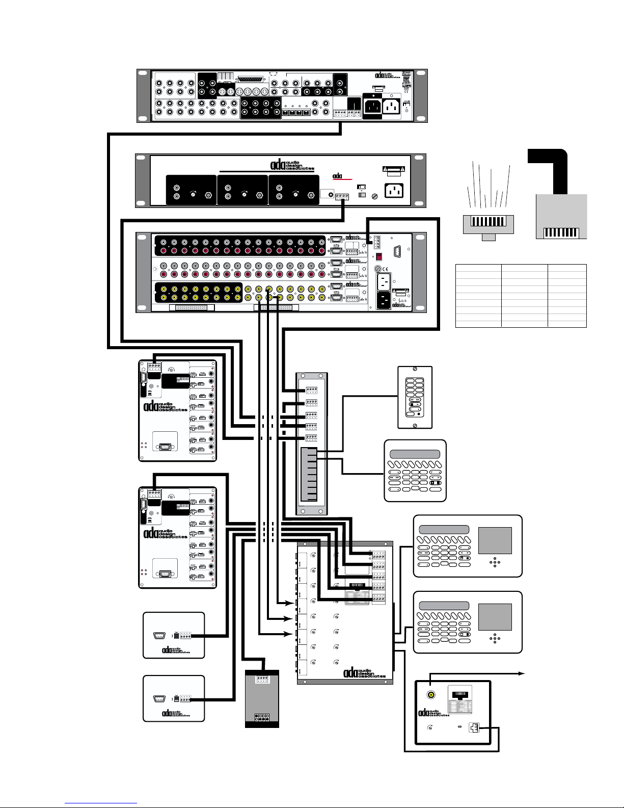
VIDEO INPUTS
RJ-45 Cat. 5 Cable Connector
Top
Front
B
R
O
W
N
B
R
O
W
N
W
H
I
T
E
G
R
E
E
N
W
H
I
T
E
O
R
A
N
G
E
O
R
A
N
G
E
W
H
I
T
E
G
R
E
E
N
B
L
U
E
B
L
U
E
W
H
I
T
E
8 7 6 5 4 3 2 1
3
5
1
2
7
4
6
8
L
L
2
3
1
4
AUDIO INPUTS
This device complies with Part 15 of the FCC Rules.
Operation is subject to the following two conditions:
1 This device may not cause harmful interference.
2 This device must accept any interference
received, including interference that may cause
undesired operation.
TUNER 1
AUDIO OUTPUT
L
OUTPUT
LEVEL
Cinema Rhapsody Mach II
VIDEO OUT
1
2
5
PIN +/-CHAN PIN +/- CHAN
1 / 14 LT 7 / 20 SBL
2 / 15 CT 8 / 21 SBR
8 CHANNEL DB-25 INPUT
3 / 16 RT 9 /10/22 SHLD
4 / 17 SB 11 / 23 R.T.A
5 / 18 SL 12 / 24 R.T.B
REC
6 / 19 SR 13 / 25 R.T.C
MUL
TI-PIN LFE SUM
0dB
+10dB
S-VIDEO INPUTS
MAIN 2341
REC
OSD
L
6
L
78
SBL LS
113
PIN
2514
POINTS
Y
1
2
L
MAIN
SUBSBR
RS
Trinity Triple Tuner
TRINITY TRIPLE TUNER
ANTENNA
AUDIO OUTPUT
TUNER 2
L
OUTPUT
LEVEL
ANTENNA
AUDIO OUTPUT
COMPONENT VIDEO
P
B/B-YPR/R-Y
DIGITAL AUDIO
INPUTS
OPTICAL INPUTS
123
TUNER 3
L
OUTPUT
LEVEL
3
Y
Y
O
4
ANTENNA
UTPUT
P
P
B/B-YPR/R-Y
B
123
P
R
4
IR Flasher
Input
RECORD
OUT
L
DATA PORT
Serial Data
ADA BusÆ
1 2 3 4
G
ND
O
UT
I
N
12
BUS
• ICC - I
NTERACTIVE COMPONENT COMMUNICATION
The Trinity Does Not
Require a BI-3000.
ADA Bus™
1 2 3 4
V
DC
"Dolby", "Pro Logic", & the double-D
Symbol are trademarks of Dolby
Laboratories. All rights reserved.
Manufactured under license from Digital
Theater Systems, Inc. US Pat. No.
5,451,942, 5,956,764, 5,974,380,
5,978,762 and other worldwide patents
issued and pending. "DTS", "DTS-ES
Extended Surround", and "Neo 6" are
trademarks of Digital Theater Systems,
Inc. © 1996, 2000 Digital Theater
Systems, Inc. All rights reserved.
Manufactured under license
12VDC OUT
100mA Max Per
DC 1
1- 2+
®
•
ADA NETô
Lucasfilm Ltd. U.S. patent numbers
5,043,970; 5,189,703; and/or 5,222,059.
European patent number 0323830.
Other U.S. and foreign patents pending.
Lucasfilm and THX are trademarks or
registered trademarks of Lucasfilm Ltd.
Surround EX is a jointly developed
technology of THX and Dolby
Laboratories, Inc., and is a trademark of
Dolby. Used under authorization.
from
DC 2
1- 2+
115 V
115V 230V
Voltage Selector
AC OUTPUT
10A~ Max Switched
115V 2/10A S.B.
230V 1/10 AS.B.
115 V
INEMA RHAPSODY MACH
OME THEATER CONTROLLER
WARNING! Risk Of Hazardous Energy! Make Proper
Connections.
CAUTION
AVERTISSEMENT! Energie Electrique Dangereuse!
RISK OF ELECTRIC SHOCK
DO NOT OPEN
Faire Des Connexions Propres Pour L'Hautparleur.
Voir La Notice De Fonctionnement.
ATTENTION!
CAUTION: Disconnect Supply Cord Before
RISQUE DE CHOC ELECTRIQUE.
NE PAS OUVRIR
Servicing.
MADE IN U.S.A.
ATTENTION: Debrancher Avant Le Depannage.
AC INPUT
115V~60Hz/230V~50Hz
CAUTION: DISCONNECT SUPPLY
CORD BEFORE SERVICING.
ATTENTION: DEBRANCHER AVANT
LE DEPANNAGE.
CAUTION
RISK OF ELECTRIC SHOCK
ATTENTION!
RISQUE DE CHOC ELECTRIQUE.
MADE IN U.S.A.
AC INPUT
II
Voltage
Selector &
Safety Fuse
On This Side
115 V
115V 230V
Use Same
Value Fuse
115V~1AS.B.
230V~.5AS.B.
DO NOT OPEN
NE PAS OUVRIR
WH-6000 & TV-6000
Cat-Link Termination
(Control, Power, & Video)
1
2 3 4 5 6 7 8 9 10 11 12 13 14 15 16
L
R
2 3 4 5 6 7 8 9 10 11 12 13 14 15
1
L
R
13579111315
2 4 6 8 10 12 14 16
VIDEO INPUTS
Video Out Room 4-6
IR Repeating Only
40KHz IR Repeat
Repeater
Serial
Frequency
IR - Serial
Reverse
(TuneBase)
Reverse
(TuneBase)
12345678Source Ports:
Frequency
12345678Source Ports:
ADA BUS
Normal
ADA BUS
Normal
1 2 3 4
1 2 3 4
Data Only
Norm Invert
Off
Repeater
Serial
IR - Serial
Data Only
Norm Invert
Off
Repeater
Serial
IR - Serial
Data Only
Norm Invert
Off
Repeater
Serial
IR - Serial
Data Only
Norm Invert
Off
Repeater
Serial
IR - Serial
Data Only
Norm Invert
Off
Repeater
Serial
IR - Serial
Data Only
Norm Invert
Off
Repeater
Serial
IR - Serial
Data Only
Norm Invert
Off
Repeater
Serial
IR - Serial
Data Only
Norm Invert
Off
Repeater
Serial
IR - Serial
Data Only
Norm Invert
Off
Repeater
Serial
IR - Serial
Data Only
Norm Invert
Off
Repeater
Serial
IR - Serial
Data Only
Norm Invert
Off
Repeater
Serial
IR - Serial
Data Only
Norm Invert
Off
Repeater
Serial
IR - Serial
Data Only
Norm Invert
Off
Repeater
Serial
IR - Serial
Data Only
Norm Invert
Off
Repeater
Serial
IR - Serial
Data Only
Norm Invert
Off
Repeater
Serial
IR - Serial
Data Only
Norm Invert
Off
1 2 3 4
Gnd Rx Tx +15V
ADA Busfi
ADA/232
RS-232
Pins
RS-232
2=Tx
3=Rx
ADA Bus
5=Com
IRL-5000
Source Controller
Power On/Off IR Macro
PGM DEL
CON ERR
1 2 3 4
Gnd Rx Tx +15V
ADA Busfi
ADA/232
RS-232
Pins
RS-232
2=Tx
3=Rx
ADA Bus
5=Com
IRL-5000
Source Controller
Power On/Off IR Macro
PGM DEL
CON ERR
Data/Carrier
IR Flasher=Remove Jumper
Serial Direct=Insert Jumper
Connect To Mainframe
Source DC Triggers &
ACC-48 AC Controllers
IR Repeating Only
40KHz IR Repeat
Data/Carrier
IR Flasher=Remove Jumper
Serial Direct=Insert Jumper
Connect To Mainframe
Source DC Triggers &
ACC-48 AC Controllers
ISO-232
RS-232
ISO-232
RS-232
ISO-232
ADA Bus To
RS-232 Converter
A-16
P-16
13579111315
V-16
2 4 6 8 10 12 14
EXPANSION PORTS
1
2
3
4
5
6
7
8
1
2
3
4
5
6
7
8
ADA Bus
Clock Module
CMB
Input Triggers
In 1-8
A-16 Audio Input Module
Balanced
Trigger
In 7/15
In 8/16
In 6/14
Audio Page
5-24V
Gnd
In 5/13
Input (600 )
AC DC
In 4/12
In 1/9
1
2
In 3/11
In 2/10
(+)3(-)4(+)5(-)
Com
Paging Input/Trigger
P-16 Preamplifier Module
Zones 13-16
+12VDC Output
Gnd
(-)13(+)14(+)15(+)16(+)
V-16 Video I/O Module
Programmed Video
Input Triggers
5-24V AC DC
Gnd
(-)1(+)2(+)3(+)
Input Triggers
ADA BusÆ
230V
115V
1/2 ASB
115V~
1/4 ASB
230V~
Switch
AC
(10A)
4
(+)
Main
AC
Input
In 9-16
+12VDC Outputs
Zones 1- 6 & 7-12
Zones 1-6
16
TO PTM-1225/1260
In 6/12
In 5/11
Gnd
In 4/10
In 1/7
In 2/8
In 3/9
Zones 7-12
+12VDC Outputs
Output Triggers
Out 1-8
Out 7/15
Out 8/16
Out 6/14
Gnd
Out 5/13
Out 1/9
Out 4/12
Out 3/11
Out 2/10
16
Out 9-16
+12VDC Outputs
ADA Bus to WH-2000 J1
WH-2000
1 2 3 4
J1
J2
WH-2000
Video
In 1
H.F. Trim
75Ω
Hi-Z
Video
In 2
H.F. Trim
75Ω
Hi-Z
Video
In 3
H.F. Trim Gain Trim
75Ω
Hi-Z
Video
In 4
H.F. Trim Gain Trim
75Ω
Hi-Z
Video
In 5
H.F. Trim Gain Trim
75Ω
Hi-Z
Video
In 6
H.F. Trim Gain Trim
75Ω
Hi-Z
Video
In 7
H.F. Trim Gain Trim
75Ω
Hi-Z
Video
In 8
H.F. Trim Gain Trim
75Ω
Hi-Z
WH-6000
J3
J4
J5
RJ45
RJ45
RJ45
RJ45
RJ45
RJ45
RJ45
RJ45
Cat-Link 1
Cat-Link 2
Cat-Link 3
Cat-Link 4
Cat-Link 5
Cat-Link 6
Cat-Link 7
Cat-Link 8
Gain Trim
Gain Trim
Cat. 5
To Any
Open
Tx
Rx
Bus Power
ADA Bus
+V Tx Rx Gnd
4 3 2 1
RJ-45 Cat-Link
8 7 6 5 4 3 2 1
Cat-Link 1 Out
Cat-Link 2 Out
Cat-Link 3 Out
Cat-Link 4 Out
Cat-Link 5 Out
Cat-Link 6 Out
Cat-Link 7 Out
Cat-Link 8 Out
WH-6000
Video Wire
Harness
Use Standard
Cat. 5
- 35 -
Network Control I/O
1 Gnd
2 Fdbk
3 Cntrl
4 +V
115 V
F
M
In
Loop
Out
I/O 1
I/O 2
I/O 3
WARNING! Risk Of Hazardous Energy!
Make Proper Connections.
AVERTISSEMENT! Energie Electrique
Faire Des Connexions Propres
Voir La Notice De Fonctionnement.
CAUTION: Disconnect Supply
ATTENTION: Debrancher
115V~/60Hz 230V~/50Hz
500 WATTS MAX
CAUTION
RISK OF ELECTRIC SHOCK
ATTENTION!
RISQUE DE CHOC ELECTRIQUE.
MADE IN U.S.A.
AVP-16 MR Controller
F
M
1
BASS
EXTRA
VOL
Dangereuse!
Pour L'Hautparleur.
Cord Before Servicing.
Avant Le Depannage.
DO NOT OPEN
NE PAS OUVRIR
DVD
OFF
A
M
2
123
456
789
*
FM2FM1
CD1AM
DSSCD2
AUX
VOL
C
C
D
D
D
S
1
2
S
0
ENT
F
F
M
M
2
1
BASS
EXTRA
VOL
F
F
M
M
2
1
BASS
EXTRA
VOL
PIN NUMBER COLOR FUNCTION
PIN 1 BROWN + 20V
PIN 2 BROWN/WHITE GND
PIN 3 GREEN/WHITE TXPIN 4 ORANGE RX +
PIN 5 ORANGE/WHITE RXPIN 6 GREEN TX+
PIN 7 BLUE + VIDEO
PIN 8 BLUE/WHITE - VIDEO
MC-5011
Room 1
A
D
U
V
D
X
MC-5000
TREB
Room 3
OFF
A
C
C
D
D
A
M
123
456
789
*
U
D
D
S
V
X
1
2
S
D
TREB
0
ENT
OFF
MC-6000 Room 4
A
C
C
D
D
A
M
123
456
789
*
U
D
D
S
V
X
1
2
S
D
TREB
0
ENT
OFF
MC-6000 Room 5
To TV
Video Output (75Ω)
RJ-45 Cat-Link
8 7 6 5 4 3 2 1
Room 6
TV-6000
Pull Shunting Pin
H.F. Gain
For Hi-Z Input
TV-6000
Cat-Link Video Receiver
Cat-Link Video Input
(From WH-6000)
Page 37
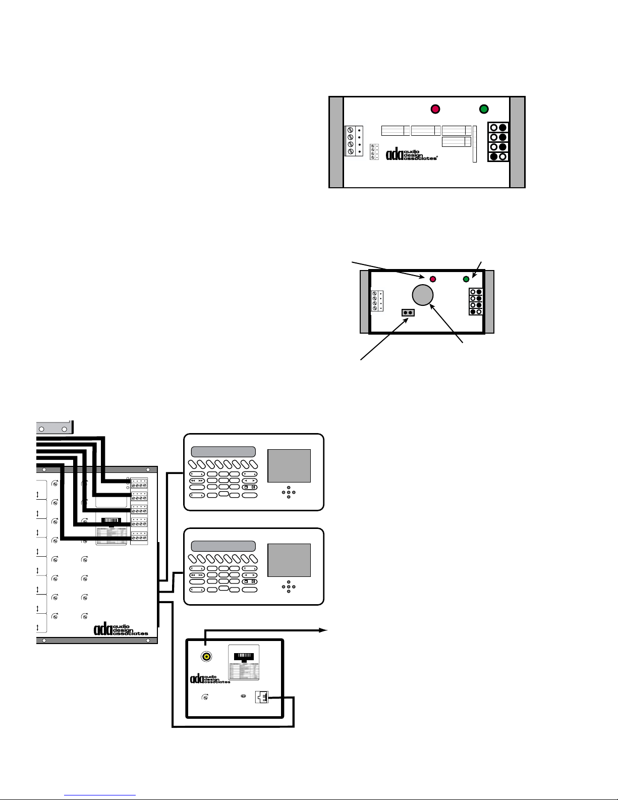
CMB-1 Clock Module
SWITCH 1234
WH 2000
The CMB-1 Clock Calendar Module is a master clock
module which calibrates all system clocks (i.e. MC5000 Keypads) on power up and from then on, every
hour. While typically powered by the ADA Bus, the
CMB-1 also features a battery backup to maintain time
during power outages. The CMB-1 will permit the MC6000, MC-5000, MC-3000 OD, and/or MC-3800 OD
keypads to display the date and time when a room is
off. In order for these keypads to display the time,
a single CMB-1 needs to be connected to an open
ADA Bus jack on any wire harness.
The CMB-1 features DIP switches which set the
Baud Rate (baud rates are either 1200 or 19200
and must match the settings of the Suite 16 System, typically 19200), the time mode (12 hour or
24 hour used only during test and setup mode),
Day Light Savings Time On or Off (US DST), and
a test mode. As the CMB-1 features a calendar it
is capable of changing the from Standard Time to
Day Light Savings Time automatically. Only one
CMB-1 is used per system.
SWITCH NO. 1
SWITCH NO. 2
19,200 BAUD UP
24 HOUR MODE UP
1,200 BAUD DN
CMB-1
12 HOUR MODE DN
Daylight Savings
Time in Auto Mode is
based on US Daylight
Savings Time.
ADA
Bus
4
3
2
1
CMB-1 Open
Red LED Flashes
CMB-1 is working.
3V (BR2032) BATTERY
Jumper Pin when pulled,
removes battery from circuit,
extending its life during extened
storage. Jumper pin must be in
place for battery to work.
SWITCH NO. 3
DAYLIGHT AUTO U P
DAYLIGHT OFF DN
SWITCH NO. 4
TEST MODE UP
NORMAL MODE DN
Test Mode On will
send the time every
minute. After testing,
set the switch to Normal Mode.
Green LED is
the power LED.
Video
Cat-Link 1
In 1
H.F. Trim
Gain Trim
Cat-Link 2
H.F. Trim
Gain Trim
Cat-Link 3
H.F. Trim Gain Trim
Cat-Link 4
H.F. Trim Gain Trim
Cat-Link 5
H.F. Trim Gain Trim
Cat-Link 6
H.F. Trim Gain Trim
Cat-Link 7
H.F. Trim Gain Trim
Cat-Link 8
H.F. Trim Gain Trim
WH-6000
Video
Video
Video
Video
Video
Video
Video
75Ω
Hi-Z
In 2
75Ω
Hi-Z
In 3
75Ω
Hi-Z
In 4
75Ω
Hi-Z
In 5
75Ω
Hi-Z
In 6
75Ω
Hi-Z
In 7
75Ω
Hi-Z
In 8
75Ω
Hi-Z
WH-6000
Video Wire
Harness
Use Standard
Cat. 5
Bus Power
ADA Bus
+V Tx Rx Gnd
4 3 2 1
RJ-45 Cat-Link
8 7 6 5 4 3 2 1
Tx
Rx
Cat-Link 1 Out
Cat-Link 2 Out
Cat-Link 3 Out
Cat-Link 4 Out
Cat-Link 5 Out
Cat-Link 6 Out
Cat-Link 7 Out
Cat-Link 8 Out
If it is preferable for some
rooms to have the
F
F
C
A
M
M
D
M
2
1
1
In
Loop
Out
I/O 1
I/O 2
I/O 3
BASS
456
789
EXTRA
VOL
*
MC-6000 Room 4
F
F
C
A
M
M
D
M
2
1
1
BASS
456
789
EXTRA
VOL
*
MC-6000 Room 5
A
C
D
D
U
D
S
V
1
2
0
X
2
S
D
3
TREB
ENT
OFF
keypad’s display turn off
rather than continuously
display room status or
time, these keypads can
be individually set to blank
out (Blanking On/Off), per-
A
C
D
D
U
D
S
V
1
2
X
2
S
D
3
TREB
mitting others to display
status or date/time. Date/
time are displayed only
0
ENT
OFF
when the room is off or the
entire system is off.
To TV
If the CMB-1 battery is
dead and the system suf-
Video Output (75Ω)
RJ-45 Cat-Link
8 7 6 5 4 3 2 1
Room 6
fers a power loss, the key-
Pull Shunting Pin
H.F. Gain
For Hi-Z Input
TV-6000
Cat-Link Video Receiver
Cat-Link Video Input
(From WH-6000)
TV-6000
pads will display CHECK
BATT/TIME after all controls have been updated.
This display will continue
every hour until the clock
has been set.
- 36 -
Page 38
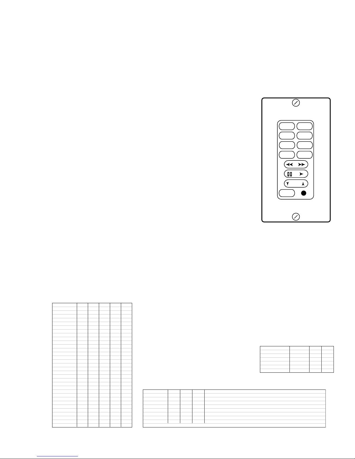
MC-5011 Keypad Setup
The MC-5011 Keypad combines both elegance, function, and price into a single-gang Decora
bezel.
The MC-5011 is only available with a Cat-Link connector. As such, the MC-5011 must be
wired on standard Cat. 5 cable. The MC-5011 controls the Suite 16 System. You must use
the WH-2000 Wiring Harness with the MC-5011 Keypad. There are eight standard pre-made
source formats which are listed below.
Format 1 FM1,FM2,AM,CD1,CD2,DSS,DVD,AUX
Format 2 FM1,FM2,AM,CD1,CD2,CD3,DSS,DVD
Format 3 FM1,FM2,AM,CD1,CD2,DSS,DSS,AUX
Format 4 FM1,FM2,FM3,CD1,CD2,DSS,DVD,AUX
Format 5 FM1,FM2,FM3,CD1,CD2,CD3,DSS,DVD
Format 6 FM1,FM2,FM3,CD1,CD2,DSS,DSS,AUX
DVD
Format 7 FM1,FM2,CD1,CD2,DSS,DSS,DVD,AUX
Format 8 FM1,FM2,CD1,CD2,DSS,DSS,AUX,AUX
Custom formats are also available at an additional charge. Please
OFF
note, that custom formats utilize a rubber button pad where the
eight source buttons are black and the lettering is etched clear. All
other keypad buttons are clear with black lettering ADA then etches
away the desired source label using a process that involves a laser.
Up to three characters can be used to describe a source name. This process is functional but
the letters are not as smooth as those of the eight more common formats listed above. Again,
the letters in a custom rubber are clear and the area around them is black. This only applies
to the eight source buttons. ADA suggests using one of the eight formats listed above.
FM2FM1
CD1AM
DSSCD2
AUX
VOL
The MC-5011 features a bank of twelve DIP Switches. Switches 1 and 2 determine system
model. Switch 3 sets baud rate (1200,19200), Switch 4 sets light dimming, Switch 5, 6, and 7
set source control, and switches 8, 9, 10, 11, and 12 set room number. There are also two
jumper “shunting pins” that determine if the MC-5011’s IR receiver is on or off. The second
DIP SWITCH # 8 9 1 0 1 1 1 2
ROOM 1 ON ON ON ON ON
ROOM 2 ON ON ON ON O FF
ROOM 3 ON ON ON OFF ON
ROOM 4 ON ON ON OFF OF F
ROOM 5 ON ON OF F ON ON
ROOM 6 ON ON OF F ON 0 F F
ROOM 7 ON ON OFF OFF ON
ROOM 8 ON ON OFF OFF OFF
ROOM 9 ON OFF ON ON ON
ROOM 10 ON OFF ON ON OFF
ROOM 11 ON OFF ON OFF ON
ROOM 12 ON OFF ON OFF OFF
ROOM 13 ON OFF OFF ON ON
ROOM 14 ON OFF OFF ON OFF
ROOM 15 ON OFF OFF OFF ON
ROOM 16 ON OFF OFF OFF OFF
ROOM 17 O FF ON ON ON ON
ROOM 18 O FF ON ON ON OFF
ROOM 19 OFF ON ON OFF ON
ROOM 20 OFF ON ON OFF OFF
ROOM 21 OFF ON OFF ON ON
ROOM 22 OFF ON OFF ON OFF
ROOM 23 OFF ON OFF OFF ON
ROOM 24 OFF ON OFF OFF OFF
ROOM 25 OFF OFF ON ON ON
ROOM 26 OFF OFF ON ON OFF
ROOM 27 OFF OFF ON OFF ON
ROOM 28 OFF OFF ON OFF OFF
ROOM 29 OFF OFF OFF ON ON
ROOM 30 OFF OFF OFF ON OFF
ROOM 31 OFF OFF OFF OFF ON
ROOM 32 OFF OFF OFF OFF OFF
jumper turns the LED’s off when the system is off. With jumper is
set to night mode, when the room is on, the keypad functions as
normal: the selected source is red, while all other buttons are
green. When the room is off but the system is still on elsewhere,
all buttons are off with the exception of the OFF button, which will
glow red, indicating the system is still
on somewhere. When the system is
off, all buttons are off. These charts
will assist in properly setting up the MC-
DIP SWITCH # 1 2 3
DELTA @ 1200 OFF OFF ON
DELTA @ 19200 OFF OFF OFF
MILLEN @ 1200 ON OFF ON
MILLEN @19200 ON OF F OFF
SUITE 16 @ 1200 ON or OFF ON ON
SUITE 16 @19200 ON or OFF ON OFF
5011.
DIP SWITCH # 5 6 7 SOURCE CONTROL OPTIOINS
SETTING 1 ON ON ON IRL-3000 SOURCES 1-8 CORRESPOND TO SOURCES 1-8
SETTING 2 ON ON OF F TRINITY TUNER SOURCES 1-3, IRL-3000 SOURCES 4-8
SETTING 3 ON OF F ON TRINITY SOURCES 1-3, SPECIAL CD 1 SOURCE 4, IRL SOURCES 5-8
SETTING 4 ON OF F OF F TRINITY SOURCES 1-3, SPECIAL CD 1 & 2 SOURCES 4 & 5, IRL SOURCES 6-8
SETTING 5 OFF ON ON TRINTIY SOURCES 1 & 2, IRL-3000 SOURCES 3-8
SETTING 6 OFF ON OFF TRINITY SOURCES 1 & 2, SPECIAL CD SOURCE 3, IRL-3000 SOURCES 4-8
SETTING 7 OFF OFF ON TRINITY SOURCES 1 & 2, SPECIAL CD 1 & 2 SOURCES 3 & 4, IRL SOURCES 5-8
SETTING 8 OFF OFF OFF IRL-3000 SOURCES 1-3 & 5-8, SPECIAL CD 1 SOURCE 4
IRL-3000 PORTS 1-8 ALWAYS CORRESPOND TO SOURCES 1-8. SPECIAL CD IS USED WITH AQUARIUS & ESCIENT PRO MK II/III
- 37 -
Page 39
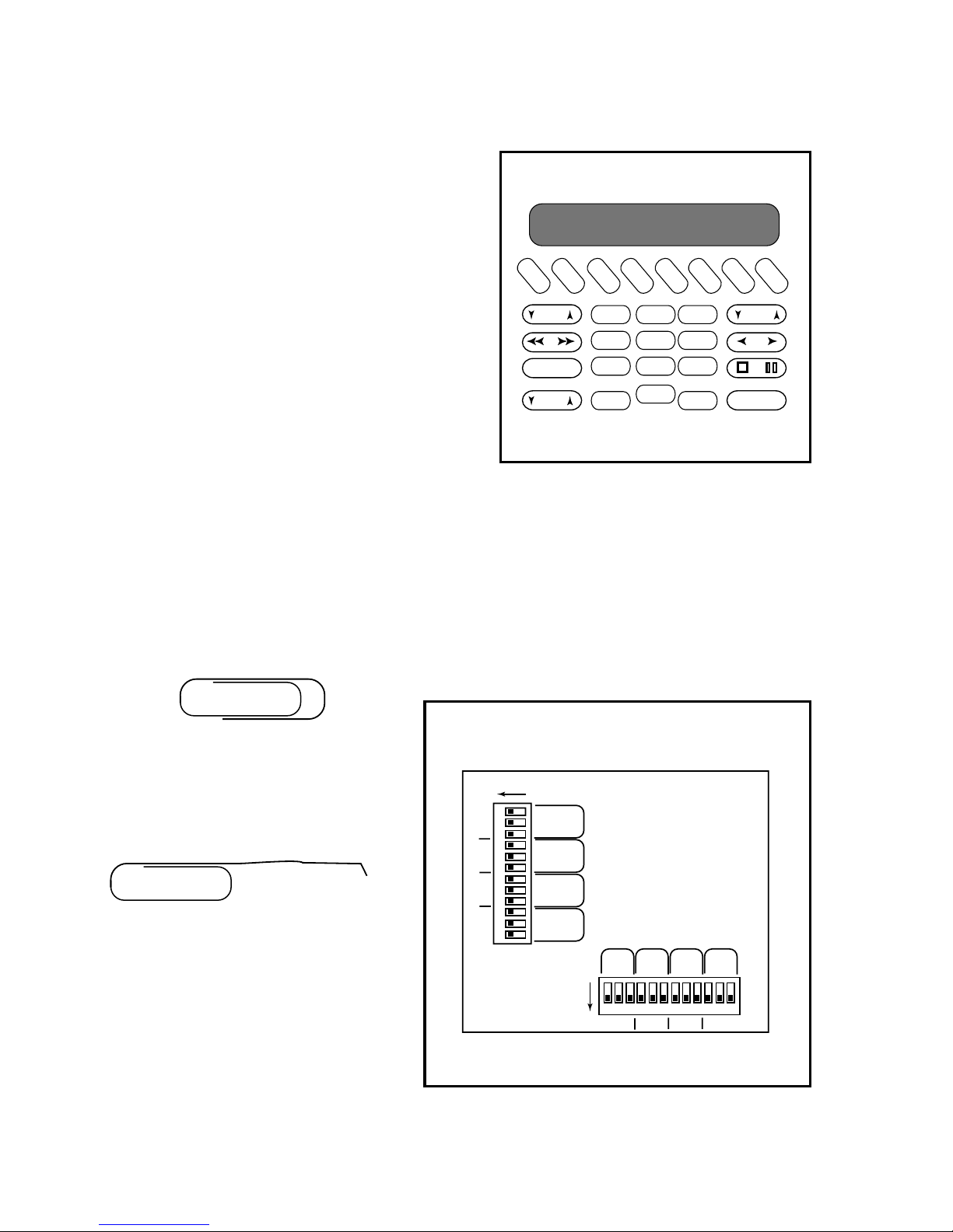
MC-5000 Keypad LED Setup
The MC-5000 Rapture Keypad is designed to permit
you to select different light colors per button groups.
The buttons are grouped together by function and
each group has three DIP switches associated to that
group. The three switches turn on red, green, and
blue individually. These switches are found on the
circuit board attached to the MC-5000 wall plate.
There are two banks of 12 switches, 24 switches total, for eight button groups.
The eight groups are: Numerics, Transports, Sources
Not Selected, Source Selected, Bass & Treble (Party
1 & 2 on Millennium), Extra, Volume, and Off.
Available Colors Include: Red, Green Blue, Purple
(Red & Blue On), Orange (Green & Red On), Light
Blue (Blue & Green On), White/Pink (Red, Green & Blue On), and No Color (All Off).
F
M
EXTRA
1
BASS
VOL
F
M
2
C
C
A
D
M
1
1
4
789
*
D
D
S
2
3
2
6
5
0
ENT
D
V
S
D
TREB
OFF
A
U
X
To set the colors, ADA suggests taking an ordinary paper clip and creating a small tool that will
allow you to turn the switches on and off as you desire.
Open the paper clip so that one end is extended straight. Using a needle-nose set of pliers,
bend the end of the tip so that the extended end has a little hook to it.
As some of the DIP switch groups are hard
to access, in particular Source Used and
Sources Not Used, this paper clip will be of
use.
ON
1 2 3 4 5 6 7 8 9
R
G
B
R
G
B
R
G
B
R
G
B
10 11 12
SOURCE
USED
SOURCES
NOT USED
BASS/TREB
PARTY 1&2
TRANSPORT
ON
VOL OFF NUMER
EXTRA
1 2 3 4 5 6 7 8 9
RGBR GBRGBRGB
10 11 12
- 38 -
Page 40
MC-5000 Keypad Manual Setup
The EXTRA button is used to both permit the user to access other keypad functions while
permitting the installer to enter the keypad’s program mode.
To enter the program mode, press and hold the EXTRA button for 5 seconds. The display will
read the keypad’s version number followed by the enter code display:
CODE: _ _ _ _
Enter the ADA code number using the eight source buttons where the source button on the far
left refers to the number 1 and the source button on the far right refers to the number 8.
The following codes activate the associated menu functions.
CODE MENU FUNCITON DESCRIPTION
1111 TEST KEYS DEMONSTRATION KEYPAD MODE
1112 IR ON/OFF TOGGLE TURNS KEYPAD IR RECEIVER ON & OFF
1113 DISPLAY BLANK TOGGLE WHEN THE SYSTEM IS OFF, THE KEYPAD DISPLAY BLANKS OUT AFTER A SHORT TIME.
1115 CLOCK SETUP SET DATE AND TIME
1116 ROOM NUMBER SETS ZONE KEYPAD ZONE NUMBER
1117 BAUD RATE 1200 SETS KEYPAD BAUD RATE TO 1200 BAUD
1118 BAUD RATE 19200 SETS KEYPAD BAUD RATE TO 19200 BAUD
1867 INSTALLER MODE SETS KEYPAD INTO PROGRAM MODE
After entering the code the display will confirm the setup mode selected.
For Code 1111, the display will read TEST KEYS. As sources are
selected, the selected source button will illuminate the active LED
color while the rest of the keypad LEDs will light up. Upon press the
source buttons, the following characters will be displayed on the twelve
character display. Pressing the Room Off button will turn off the source
LED’s. Pressing the Extra button will indicate EXTRA and then the
keypad will exit the Test Keys mode and return to normal operation.
IR Receiver On/Off Toggle
For Code 1112, the display will read IR ON or IR OFF depending on
the state of the IR. Re-entering this code will reverse the process.
Keypad Display Time Out - Bedroom Mode
For Code 1113, the display will read BLANKING ON or BLANKING
OFF, depending on the state of the readout display. Display will black
out after 5 seconds after receiving a feedback update.
Room Address
For Code 1116, the display will read the current room number:
SET ROOM # (where the # is the current room number)
BUTTON DISPLAY
SOURCE 1 FM TUNER 1
SOURCE 2 FM TUNER 2
SOURCE 3 AM
SOURCE 4 CD PLAYER 1
SOURCE 5 CD PLAYER 2
SOURCE 6 DSS RECEIVER
SOURCE 7 DVD PLAYER
SOURCE 8 AUXILIARY
BASS UP BASS UP
BASS DN BASS DOWN
TREB UP TREBLE UP
TREB DN TREBLE DOWN
VOL UP VOLUME UP
VOL DN VOLUME DOWN
11
22
33
44
55
66
77
88
99
00
**
ENTER ENTER
>> FAST FORWARD
<< REWIND
> PLAY
< REVERSE
STOP STOP
PAUSE PAUSE
To change the room number of the keypad, use the >> or <<. Room numbers will increment
between 1 and 99. Press EXTRA to exit the setup mode and the display will momentarily
read ROOM = # and then the display will return to normal operation.
- 39 -
Page 41

1200 Baud Rate
For Code 1117, the display will read BAUD 1200. If the display maintains BAUD 1200, the
keypad is not communicating with the Suite 16. As such, this may be the wrong baud rate
setting.
19200 Baud Rate
For Code 1118, the display will read BAUD 19200. If the display maintains BAUD 19200, the
keypad is not communicating with the Suite 16. As such, this may be the wrong baud rate
setting.
Clock and Calendar (This function only works if the control is connected to a system
that includes the CMB-1 Clock Calendar Module. The CMB-1 must be on the bus.)
For Code 1115, the display will read CLOCK SET. Use the < or > buttons to select which of
the following parameters you wish to change.
SET HOURS.-SET MINUTES-SET MONTH-SET DATE-SET DAY-SET 12-24 HR-SET YEAR
The SET 12-24 HR function refers to the clock displaying time in 12 hour mode or 24 hour
mode. This setting is independent of that on the CMB-1 and is set locally. As such, some
keypads can display time in 12 hour mode while others display time in 24 hour mode.
Regarding the setting of seconds, any adjustment to minutes resets the seconds to zero.
All changes are accepted immediately.
SET HOURS - When you navigate to the SET HOUR display using the < or > buttons, pressing the << or >> button only once, will cause the display to read the current state without
changing any of the settings, as an example:
FEB14 23:33 or FEB14P11:33
(“P” stands for p.m. when in 12 hour mode. No character is displayed for a.m.)
While the keypads can be set to display either 12 or 24 hour modes independently of the
setting of the CMB-1, during time/date setup, the CMB-1’s 12/24 hour mode setting will dominate the display. Use the >> or << to alter the hour. If in 24 hour mode (set 12 or 24 Hour
mode using DIP switches on the CMB-1), the time will increment through 24 hours. If in the
12 hour mode, the clock will display “P” for p.m.
SET MINUTES - After setting the hour, use the > button to advance the display to SET MINUTES and then press << or >> once. Again the display will read the current date and time, as
an example, FEB14 23:33. At this time, pressing >> or << will advance or decline through
minutes. When the desired time is displayed, use the > button to advance to:
SET MONTH - After setting the minutes, use the > button to advance the display to SET
MONTH and then press << or >> once. Again the display will read the current date and time,
as an example, FEB14 23:33. At this time, pressing >> or << will advance or decline through
the twelve month. When the desired month is displayed, use the > button to advance to:
- 40 -
Page 42

SET DATE - After setting the month, use the > button to advance the display to SET DATE
and then press << or >> once. Again the display will read the current date and time, as an
example, FEB14 23:33. At this time, pressing >> or << will advance or decline through the
numeric date. When the desired date is displayed, use the > button to advance to:
SET DAY - After setting the date, use the > button to advance the display to SET DAY and
then press << or >> once. The display will read the current day, as an example, THU. At this
time, pressing >> or << will advance or decline through the seven days. When the desired
day is displayed, use the > button to advance to:
SET 12-24 HR - After setting the day, use the > button to advance the display to SET 12-24
HR and then press << or >> once. The display will read 12 HOUR MODE or 24 HOUR
MODE. At this time, pressing >> or << will switch between these two options. While all other
features are loaded into the CMB-1, thus not requiring you to do this process for each and
every keypad, the 12/24 display setting must be altered on a per keypad basis. This is the
only Clock/Calendar associated setting that is not global. When the desired clock mode is
displayed, use the > button to advance to:
SET YEAR - After setting the 12/24 hour mode, use the > button to advance the display to
SET YEAR and then press << or >> once. The display will read the current year, as an
example, 2002. At this time, pressing >> or << will advance or decline through the available
years (2000-2099). For systems that are still operational in 3000, ADA will suggest upgrading
the MC-5000 software. When the desired month is displayed, use the > button to advance
back to SET HOURS or press the EXTRA button to exit this setup mode.
Exiting the Clock/Calendar Setup
If you wish to exit this setup mode at any given time, press the EXTRA button.
MC-5000 Installer Setup
Unlike the previous setup features, those found under Installer Setup are more involved to the
systems underlying programming. It is here, that the feature set of the MC-5000 when used
with the Suite 16 System is fully realized. Prior to entering the code the Version # will appear.
To enter the installer area, press and hold the extra button until the display reads:
CODE __ __ __ __
Enter the code “1867” using the source buttons where the number one is the first source on
the left while the number eight is the last source, that on the far right. When the code is
entered correctly, the display will read:
INSTALLER
The first stage of this sequence is the connection of the keypad’s eight source buttons to the
16 inputs on the Suite 16. Pressing the >> or << buttons will advance through these options:
INPUT CONFIG - SOURCE CNTRL - SOURCE LABEL - CHECK SETUP - PROGRAM ALL
- 41 -
Page 43

Input Configuration
While the display reads INPUT CONFIG pressing the > button will engage the input configuration mode. The display will read:
NORMAL INPUT
Here there are a total of five options, the most common of which the normal input configuration option is the most common:
NORMAL INPUT - PARTYGROUP 1 - PARTYGROUP 2 - PARTY GROUP 3 - PARTYGROUP 4
By pressing >> or <<, you will be able to advance through the above five options. Again,
pressing < will return you to the previous level. When you have selected one of the above
options, such as NORMAL INPUT, press the > button. The display will then read the first input
option:
INPUT 0
Pressing >> or << buttons will scroll through all of the seventeen options under the headings
found in the table below. To return to the previous level, press the < button.
NORMAL INPUT PARTYGROUP 1 PARTYGROUP 2 PARTYGROUP 3 PARTYGROUP 4
INPUT 0 PTYGRP1-IN 0 PTYGRP2-IN 0 PTYGRP3-IN 0 PTYGRP4-IN 0
INPUT 1 PTYGRP1-IN 1 PTYGRP2-IN 1 PTYGRP3-IN 1 PTYGRP4-IN 1
INPUT 2 PTYGRP1-IN 2 PTYGRP2-IN 2 PTYGRP3-IN 2 PTYGRP4-IN 2
INPUT 3 PTYGRP1-IN 3 PTYGRP2-IN 3 PTYGRP3-IN 3 PTYGRP4-IN 3
INPUT 4 PTYGRP1-IN 4 PTYGRP2-IN 4 PTYGRP3-IN 4 PTYGRP4-IN 4
INPUT 5 PTYGRP1-IN 5 PTYGRP2-IN 5 PTYGRP3-IN 5 PTYGRP4-IN 5
INPUT 6 PTYGRP1-IN 6 PTYGRP2-IN 6 PTYGRP3-IN 6 PTYGRP4-IN 6
INPUT 7 PTYGRP1-IN 7 PTYGRP2-IN 7 PTYGRP3-IN 7 PTYGRP4-IN 7
INPUT 8 PTYGRP1-IN 8 PTYGRP2-IN 8 PTYGRP3-IN 8 PTYGRP4-IN 8
INPUT 9 PTYGRP1-IN 9 PTYGRP2-IN 9 PTYGRP3-IN 9 PTYGRP4-IN 9
INPUT 10 PTYGRP1-IN10 PTYGRP2-IN10 PTYGRP3-IN10 PTYGRP4-IN10
INPUT 11 PTYGRP1-IN11 PTYGRP2-IN11 PTYGRP3-IN11 PTYGRP4-IN11
INPUT 12 PTYGRP1-IN12 PTYGRP2-IN12 PTYGRP3-IN12 PTYGRP4-IN12
INPUT 13 PTYGRP1-IN13 PTYGRP2-IN13 PTYGRP3-IN13 PTYGRP4-IN13
INPUT 14 PTYGRP1-IN14 PTYGRP2-IN14 PTYGRP3-IN14 PTYGRP4-IN14
INPUT 15 PTYGRP1-IN15 PTYGRP2-IN15 PTYGRP3-IN15 PTYGRP4-IN15
INPUT 16 PTYGRP1-IN16 PTYGRP2-IN16 PTYGRP3-IN16 PTYGRP4-IN16
Input 0 or any of the party group inputs that read 0 refer to no source selection at all. These
options are useful to prevent a source button from selecting anything on that button (i.e. a
source button that does nothing).
To lock a keypad’s source button into one of the above inputs, press the source button while
the keypad displays the corresponding input setting. The keypad will echo INPUT OK while
the source button pressed will illuminate, indicating that the setting has been locked in. If you
have a 0 input setting displayed and you then press a source button, the display will indicate
NO INPUT OK. Continue setting all eight source buttons. To return to a previous level, press
the < button. To return to the main Installer area, press the < button again.
- 42 -
Page 44

Party Group Source Selection
The Party Group source selection feature permits multiple rooms to engage to the selected
source when a single keypad accesses that source. This feature is used to setup “party” type
sources in several rooms when entertaining. In this application, not all sources on a keypad
need be set to party. In fact, the keypads in the zones set to party, might not have a single
party function on them. Perhaps only one keypad, (i.e. kitchen), might have a single button
(i.e. CD1) that will cause the living room, dining room, and entry foyer to engage to CD with
the kitchen. Here the kitchen CD1 button will need to access a Party Input which would be
programmed on that keypad’s button as illustrated on the previous page. The three other
rooms would need to be programmed to track that specific party group using ADA’s Suite 16
setup software (PC based software).
The Party Group source selection function is also used to make certain that several zones
turn on together and continuously track the same source. For example, if a living room, dining
room, and entry foyer require independent volume, bass and treble settings, they need to be
each their own zone. However, if these three areas are open to each other, there may be a
desire to prevent different sources from ever playing simultaneously in these zones/rooms.
As such, these rooms can be set to turn on together but never play a different source. To do
so, one of the Suite 16’s four Party Groups will need to be dedicated to this group of zones/
rooms. Each of the rooms keypads will need to be programmed so that the source buttons on
these keypads engage sources specific to that party group. Finally, in software, using the
ADA Suite 16 PC Software, all these zones/rooms will need to be set to the corresponding
party group.
Exiting Input Configuration
To exit the Input Configuration mode from the deepest level, press the < button to return from
the INPUT # to the NORMAL INPUT level. Press the < again to return to INPUT CONFIG and
following options:
NORMAL INPUT - PARTYGROUP 1 - PARTYGROUP 2 - PARTY GROUP 3 - PARTYGROUP 4
Source Control
To advance to the SOURCE CNTRL option press the << or >> button until the display reads:
SOURCE CNTRL
Then press the > button. The display will read IR LEARNER. To advance to one of the
following, press the >> or << buttons. To return to the previous level, press the < button.
IR LEARNER - ADA TUNER - SPECIAL CD - LVI - NO FUNCTION
The above five options refer to the various source control options that are built into the MC6000 keypad. By moving the >> or << so that the display reads IR LEARNER, you are ready
to lock in sources to an IR LEARNER port. Press > to select the IR LEARNER while it is
displayed.
The NO FUNCTION permits you to have a source button perform no transport functions at
all. To do this, while NO FUNCTION is displayed, press the source button. The display will
confirm NONE OK.
- 43 -
Page 45

IRL-5000
Once you press the > button while IR LEARNER is displayed, the display will change to read:
IRL ADDRESS1
Using the >> and << buttons, you can advance through the following options. Use the <
button to return to the previous level.
IRL ADDRESS1 IRL ADDRESS2 IRL ADDRESS3 IRL ADDRESS4 IRL ADDRESS5 IRL ADDRESS6 IRL ADDRESS7 IRL ADDRESS8 IRL ADDRESS9
While the display reads IRL ADDRESS1, pressing the > button will take you to the next level
where the display will read:
IRL 1 OUT 1
To lock this IRL-5000 output port number to a specific source, press the source button. The
display will confirm IRL OK and return to the above setting. To advance to other IRL-5000
port outputs on an IRL-5000 with the like address, use the >> or << buttons. The options
listed below will be scrolled through.
IRL1 OUT1 - IRL1 OUT2 - IRL1 OUT3 - IRL1 OUT4 - IRL1 OUT5 - IRL1 OUT6 - IRL1 OUT7 - IRL1 OUT8
Again, once a desired output port is displayed, press the corresponding source button. The
display will indicate IRL OK to verify the selection. As always, use the < button to return to the
previous level. If the wish to exit the IRL-5000 from this level, you will need to hit the < button
twice. The first time will return you to the IRL ADDRESS1 stage and the second time to the IR
learner stage where the display will again read IR LEARNER.
ADA Tuner
To advance to the ADA Tuner, use the >> or << buttons. When the display reads:
ADA TUNER
Press the > button to enter this option. The display will read:
TUNER ADRS 1
Using the >> or << buttons, you can scroll to the address of the Tuner (this is not the module
output number). Typically, Address 1 is the default address used and should not be changed.
Unless you changed the address, when the display reads TUNER ADRS1, press the > button. The display will then read:
TUNER1-OUT1
To return to the previous level, press <. To advance to other Tuner Module Outputs, use the
>> or << buttons.
TUNER1-OUT1 TUNER1-OUT2 TUNER1-OUT3
To engage a particular Tuner Module Output, press the corresponding source button. The
keypad will respond TUNER OK, indicating that the source button will now track this output.
- 44 -
Page 46

Exiting Trinity Tuner Setup
To exit the Trinity Tuner from the lowest level, you will need to press the < button twice. The
first time will return you to the address level, the second time will return you to ADA TUNER
with the following options available.
IR LEARNER - ADA TUNER - SPECIAL CD - LVI - NO FUNCTION
Using the >> or << buttons, you can proceed to Special CD or LVI. By pressing the < button
you can return to the primary menu level which includes the following:
INPUT CONFIG - SOURCE CNTRL - SOURCE LABEL - CHECK SETUP - PROGRAM ALL
Special CD
To engage a special CD setting, you must first be certain that you have a component that
specifically operates on ADA Special CD commands. ADA’s Aquarius Hard Drive, Escients
Tunebase Pro Mk II and III, or Media Access Solutions Hard Drive players are embedded with
the Special CD command sets.
To navigate to this setting, make certain you are in the SOURCE CNTRL level and using the
>> or << buttons, advance until the display reads:
SPECIAL CD
Then press >. The display will read:
SPECIAL CD 1
were as many as eight options exist including the following:
SPECIAL CD 1 SPECIAL CD 2 SPECIAL CD 3 SPECIAL CD 4 SPECIAL CD 5 SPECIAL CD 6 SPECIAL CD 7 SPECIAL CD 8
To lock a source button to track one of the special cd options, press the source button while
the display shows the corresponding Special CD address number. The display will confirm
CD OK. To advance to an alternate address setting, press the >> or << button. To return to
the previous level, press the < button.
LVI-3800
The LVI-3800 is a low voltage relay control device that provides up to seven contact closures
corresponding to a keypads: >, <, >>, <<, stop, pause, and main buttons. It is useful for
controlling devices that lack either an IR or RS-232 control interface. To lock a source button
to control the LVI-3800, make certain that you are in the SOURCE CNTRL. Use the >> or <<
buttons to navigate until the display reads:
LVI
Press > to enter the LVI menu and the display will read LVI 1 with eight possible options. Use
the >> or << buttons to advance between these options LVI 1 through LVI 8. When the
desired LVI address is displayed, press the source button and the keypad will confirm LVI OK.
To exit this level, press the < button.
No Function
When NO FUNCTION is displayed, pressing a source button will cause that source’s transport buttons to have absolutely no source control. The display will confirm NONE OK.
- 45 -
Page 47
Source Labels
Source Labels are the names of the sources that are connected to the Suite 16. While the
keypad buttons have only a few buttons to designate a source name, the keypad’s display
can read up to eleven characters. This permits you to better define that component. Whether
you are using eight or less sources, more than eight, or the full sixteen sources on a Suite 16
System, the keypads need to be programmed with all sixteen input names. By default, inputs
9-16 are pre-labeled in the keypads as INPUT 9 through INPUT 16.
INPUT CONFIG - SOURCE CNTRL - SOURCE LABEL - CHECK SETUP - PROGRAM ALL
To do so, while in the setup mode above, use the >> or << buttons until the display reads:
SOURCE LABEL
Then press the > button. The display will offer two options:
STNDRD LABEL or CUSTOM LABEL
Where the display will read
STNDRD LABEL
Then press >. The display will read
FORMAT 1
Using the >> or << buttons will advance through the following alternatives.
FORMAT 1 FORMAT 2 FORMAT 3 FORMAT 4 FORMAT 5 FORMAT 6 FORMAT 7 FORMAT 8
The table below shows the labels associated with the options selectable above.
Format 1 FM TUNER 1 FM TUNER 2 AM TUNER CD PLAYER 1 CD PLAYER 2 DSS DVD PLAYER AUXILIARY
Format 2 FM TUNER 1 FM TUNER 2 AM TUNER CD PLAYER 1 CD PLAYER 2 CD PLAYER 3 DSS DVD PLAYER
Format 3 FM TUNER 1 FM TUNER 2 AM TUNER CD PLAYER 1 CD PLAYER 2 DSS 1 DSS 2 AUXILIARY
Format 4 FM TUNER 1 FM TUNER 2 FM TUNER 3 CD PLAYER 1 CD PLAYER 2 DSS DVD PLAYER AUXILIARY
Format 5 FM TUNER 1 FM TUNER 2 FM TUNER 3 CD PLAYER 1 CD PLAYER 2 CD PLAYER 3 DSS DVD PLAYER
Format 6 FM TUNER 1 FM TUNER 2 FM TUNER 3 CD PLAYER 1 CD PLAYER 2 DSS 1 DSS 2 AUXILIARY
Format 7 FM TUNER 1 FM TUNER 2 CD PLAYER 1 CD PLAYER 2 DSS 1 DSS 2 DVD PLAYER AUXILIARY
Format 8 FM TUNER 1 FM TUNER 2 CD PLAYER 1 CD PLAYER 2 DSS 1 DSS 2 AUXILIARY 1 AUXILIARY 2
All Formats INPUT 9 INPUT 10 INPUT 11 INPUT 12 INPUT 13 INPUT 14 INPUT 15 INPUT 16
Input 1 Input 2 Input 3 Input 4 Input 5 Input 6 Input 7 Input 8
Input 9 Input 10 Input 11 Input 12 Input 13 Input 14 Input 15 Input 16
To select an option use the >> or << buttons to navigate to the Option Number and then press
the > button. That label set will be applied to the first eight sources. The display will read
LABEL OK.
To exit the standard format option level, press the < button. The display will return to STNDRD
LABEL with the following options.
STNDRD LABEL CUSTOM LABEL
- 46 -
Page 48

To completely exit the Source Label area, press the < button. To customize source labels for
either the first eight or all sixteen source labels, use the >> or << buttons until the display
reads:
CUSTOM LABEL
Then press the > button. The display will read the first of sixteen inputs.
INPUT 1
Using the >> or << buttons, you can navigate through all 16 source inputs. When the display
is on an input whose label you wish to alter, press the > button. The first character will blink on
the selected label.
You have two options here, a character by character changing of the label and/or a selection
from a pre-made source label list. Use the VOL UP or VOL DN buttons to access the 41 premade options. Use the STOP and PAUSE buttons to change the blinking character. When
done, use the >> or << buttons to advance the cursor to the next or previous character.
Repeat this until the display reads the name as you wish it to appear. Press > to lock in
changes and the display will confirm LABEL OK.
To change other input source labels, use the < button to return to the previous input label
level. Here, you can use the >> or << buttons to navigate to a different input. Again, press >
to edit this label. To completely exit the source label menu, press the < button until the display
reads CUSTOM LABEL. Then press the < button once more to return to the main setup menu
with the options shown below.
INPUT CONFIG - SOURCE CNTRL - SOURCE LABEL - CHECK SETUP - PROGRAM ALL
Check Setup
When CHECK SETUP is displayed, press the > to verify keypad source buttons to input
numbers, source labels, and source control settings for that input. Select the source and the
display will cycle between these three settings. To step back to the previous level, press the
< button.
Program All
Program All takes the information, including keypad source buttons to input assignments,
source control assignments, and source labels and uploads them to all other keypads currently on the ADA Bus. If you have some keypads currently on the ADA Bus that are custom
programmed, you will want to disconnect them because the Program All function will load
them with the programming that is internal to the keypad that is initiating the Program All. To
program other keypads, use the >> or << buttons to navigate through the following
INPUT CONFIG - SOURCE CNTRL - SOURCE LABEL - CHECK SETUP - PROGRAM ALL
until the display reads: PROGRAM ALL
Then press the > button. UPLOAD READY To abort, press the < button.
To begin the upload, press the > button. The keypad that is uploading will display UPLOADING. The keypads being programmed will read PROGRAMMING. When the programming is
complete, the keypad will exit the Installer Mode and the displays will read UPLOAD DONE
and PROGRAM DONE respectively.
- 47 -
Page 49
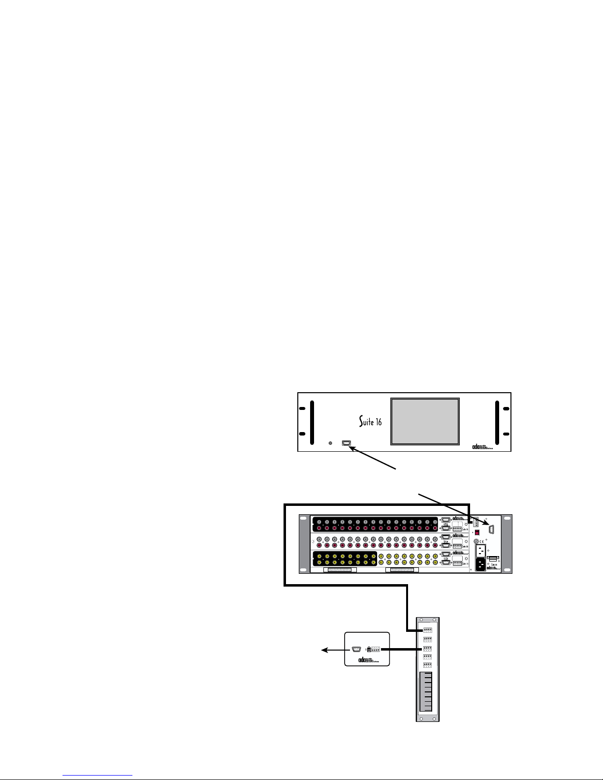
RS-232 Connections for PC’s & Control Systems
The AVP-16 chassis features two RS-232 ports, one on the front of the chassis and a second
one on the rear panel. These two RS-232 ports are in parallel. As such only one port can be
used at any one time. If you have a PC or external control system connected to the rear panel
RS-232 port, the front panel port will not be functional. The same is true if you have the front
port active, then the rear panel port will not be active.
Ideally, you want to leave either the front panel (or perhaps the rear panel) port available for
connection of a PC. This will permit you to connect your lap top PC to the Suite-16 System so
that you can use the two following PC based programs, the Keypad Uploader and Suite 16
Tester.
The Keypad Uploader program permits you to program MC-5000, MC-6000, MC-3000, MC3800, MC-3000 OD and MC-3800 OD keypads without having to enter the keypads program
steps. The Suite-16 Tester program is most useful for system set up. In most cases, you will
need to use a PC to fully access all the feature sets of Suite 16. As such, this program and its
ability to connect to the AVP-16 is essential.
Communication Settings
While the baud rate on the Suite 16 is adjustable between 1200 and 19200 baud, the typical
setting used is 19200 baud. Other settings are 8 Data Bits, 1 Stop Bit, & No Parity.
ISO-232 & External Control Systems
If you are also controlling the Suite 16 System
from an external control system (i.e. AMX or
Crestron), ADA strongly suggests adding an
ISO-232 to the system. In addition to leaving
either the front or rear panel RS-232 jack open
for your PC, the ISO-232 provides electrical
isolation that is not internal to the AVP-16’s RS232 ports. This isolation will be useful in helping to eliminate ground loops. The ISO-232
can connect directly to any open ADA Bus port
on the system wire harness or if no other ADA
Bus components are used in the system, including any ADA keypads, directly into the ADA
Bus jack on the AVP-16.
RS-232 Cable
The connection of PC or Control System to an ADA RS-232 port requires a
simple straight through 9-pin “D” style
RS-232 cable. You should not use a
To RS-232 Control
System or AMX or
Crestron Control System
null-modem or cross-over cable. If you
use an alternate type of cable, you will
most likely not get communication, in the
form of feedback or control to occur.
POWER RS-232
AVP-16
Use either front or rear panel RS-232 port
to connect to your PC. Do not use both at same time.
1
2 3 4 5 6 7 8 9 10 11 12 13 14 15 16
L
R
2 3 4 5 6 7 8 9 10 11 12 13 14 15
1
L
R
VIDEO INPUTS
13579111315
2 4 6 8 10 12 14 16
A-16
P-16
13579111315
V-16
2 4 6 8 10 12 14
EXPANSION PORTS
ADA Bus to WH-2000 J1
ISO-232
ADA BUS
RS-232
Normal
Reverse
1 2 3 4
(TuneBase)
ISO-232
ADA Bus To
RS-232 Converter
16
16
WH-2000
1 2 3 4
J1
J2
J3
J4
J5
RJ45
RJ45
RJ45
RJ45
RJ45
RJ45
RJ45
RJ45
WH-2000
Input Triggers
In 1-8
A-16 Audio Input Module
Balanced
In 7/15
In 8/16
In 6/14
Audio Page
Gnd
In 5/13
Input (600 )
In 4/12
In 1/9
1
In 3/11
In 2/10
Com
In 9-16
+12VDC Outputs
Paging Input/Trigger
Zones 1- 6 & 7-12
Zones 1-6
P-16 Preamplifier Module
TO PTM-1225/1260
In 6/12
In 5/11
Gnd
+12VDC Output
In 1/7
In 4/10
Gnd
In 2/8
In 3/9
(-)13(+)14(+)15(+)16(+)
Zones 7-12
+12VDC Outputs
Output Triggers
Out 1-8
V-16 Video I/O Module
Programmed Video
Out 7/15
Out 8/16
Out 6/14
Gnd
Out 5/13
Out 1/9
Out 4/12
Gnd
Out 2/10
Out 3/11
(-)1(+)2(+)3(+)
Out 9-16
+12VDC Outputs
Input Triggers
Network Control I/O
1 Gnd
2 Fdbk
Trigger
5-24V
3 Cntrl
AC DC
2
4 +V
(+)3(-)4(+)5(-)
ADA BusÆ
230V
115 V
115V
1/2 ASB
Zones 13-16
115V~
WARNING! Risk Of Hazardous Energy!
Make Proper Connections.
1/4 ASB
AVERTISSEMENT! Energie Electrique
Dangereuse!
230V~
Faire Des Connexions Propres
Pour L'Hautparleur.
Voir La Notice De Fonctionnement.
CAUTION: Disconnect Supply
Switch
Cord Before Servicing.
ATTENTION: Debrancher
AC
Avant Le Depannage.
(10A)
115V~/60Hz 230V~/50Hz
500 WATTS MAX
Input Triggers
5-24V AC DC
CAUTION
RISK OF ELECTRIC SHOCK
4
(+)
DO NOT OPEN
ATTENTION!
RISQUE DE CHOC ELECTRIQUE.
NE PAS OUVRIR
MADE IN U.S.A.
Main
AC
Input
AVP-16 MR Controller
- 48 -
Page 50
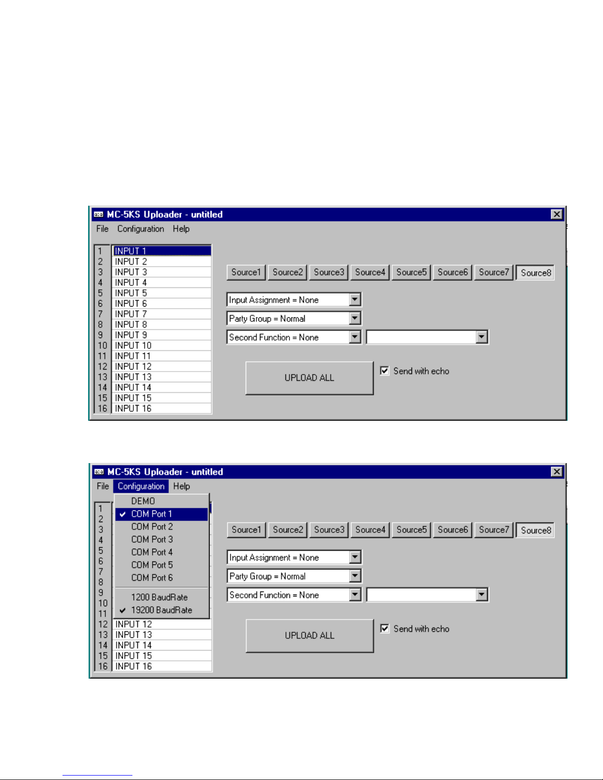
Keypad Uploader Program (MC-5KS Uploader)
ADA’s MC-5KS Uploader program is designed to speed you through the process of program-
ming keypad button input links, source control links, and source labels. Furthermore, you can
retain a saved version of the project as a “.5KS” file type, permitting you to open the setup
parameter file at future times.
To connect the PC to the system, you can use the front panel RS-232 jack on the AVP-16
providing that the rear panel RS-232 is not used. You can also connect using an ISO-232.
Use a straight-through 9-pin RS-232 cable.
After installing the Keypad Uploader program on your PC, open the program and proceed
with these first steps.
Under Configuration, select your Com port and baud rate. Unless you have specifed or have
purposely selected the 1200 baud rate setting for the Suite-16, the factory setting for the
system is 19200. As such, in the setup software, you will need to select 19200 as well.
- 49 -
Page 51
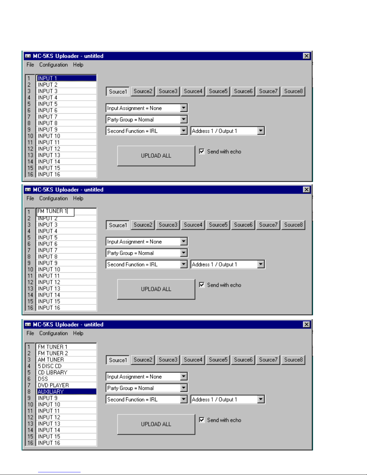
Begin by labeling your inputs. Select an input label, by default labeled 1 through 16, which
will then be outlined in blue. You can label each source with only 11 characters.
- 50 -
Page 52
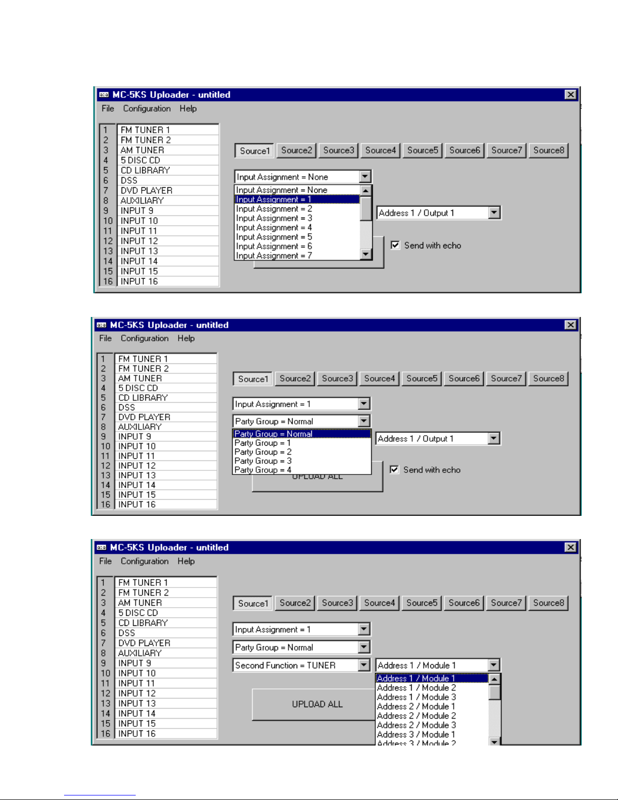
Now select the Source button representative of the eight source buttons on ADA keypads and
assign a Suite 16 Input to it.
Determine if the keypad button is a normal input or if it will activate a Suite 16 Party Group.
Finally, assign the source control option, in this example Trinity Tuner, Module 1.
- 51 -
Page 53
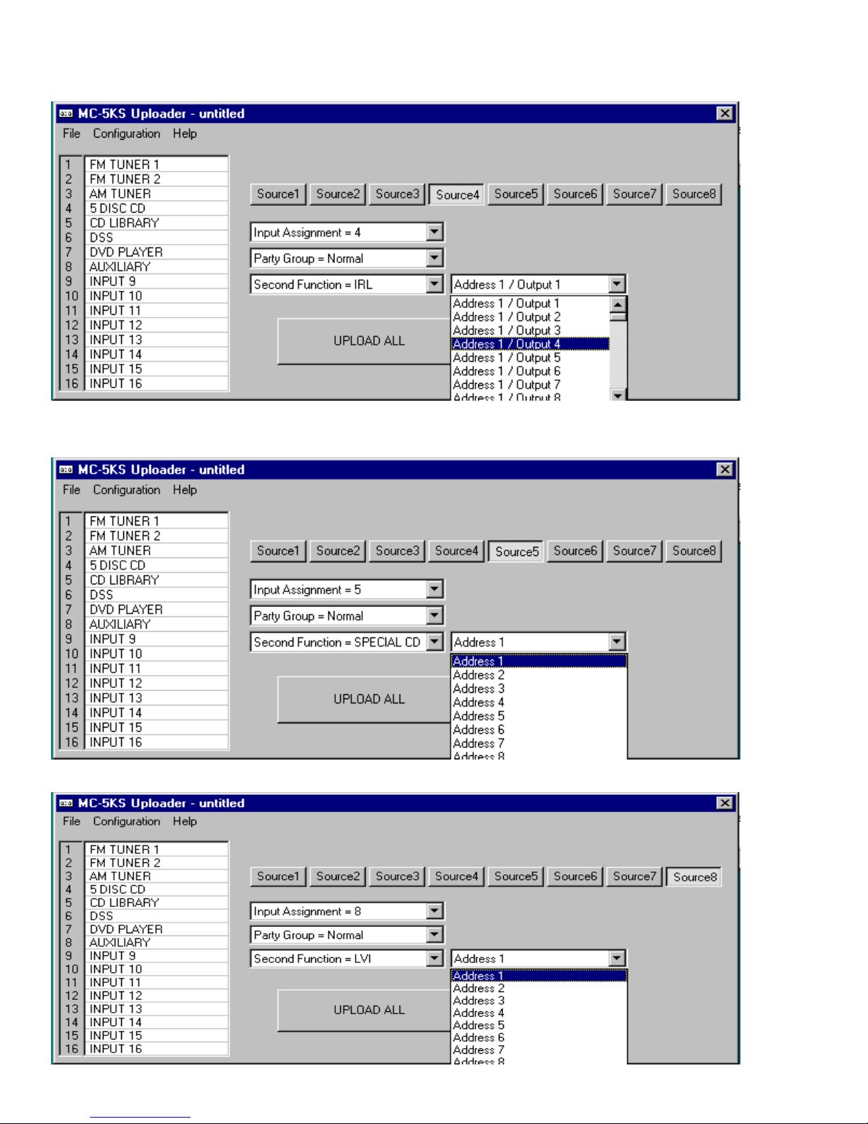
For sources that are controlled by the IRL-5000, you can assign both an address and port.
For the Special CD option, to control and get feedback from the Aquarius Hard Drive Server,
select the source button and assign a Special CD Address.
For sources that are controlled by the LVI-388 Low Voltage Relay device, assign as below.
- 52 -
Page 54
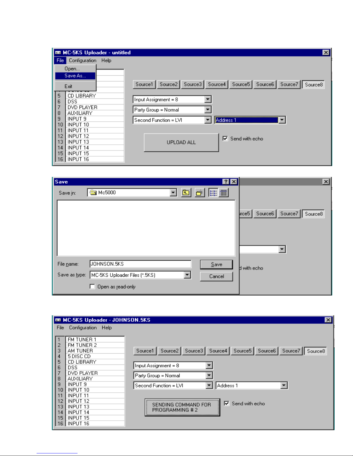
Once you have the customer’s MC-5000 configuration established, you can opt to save it as
a “.5KS” file type. As such you can reload these settings at a later time.
Under File, select Save As and enter a customer name with the “5KS” suffix and press save.
To upload the settings to the MC-5000 keypads, simply press the UPLOAD ALL button. The
software will indicate the status of the upload as well as prompting you when it is completed.
- 53 -
Page 55
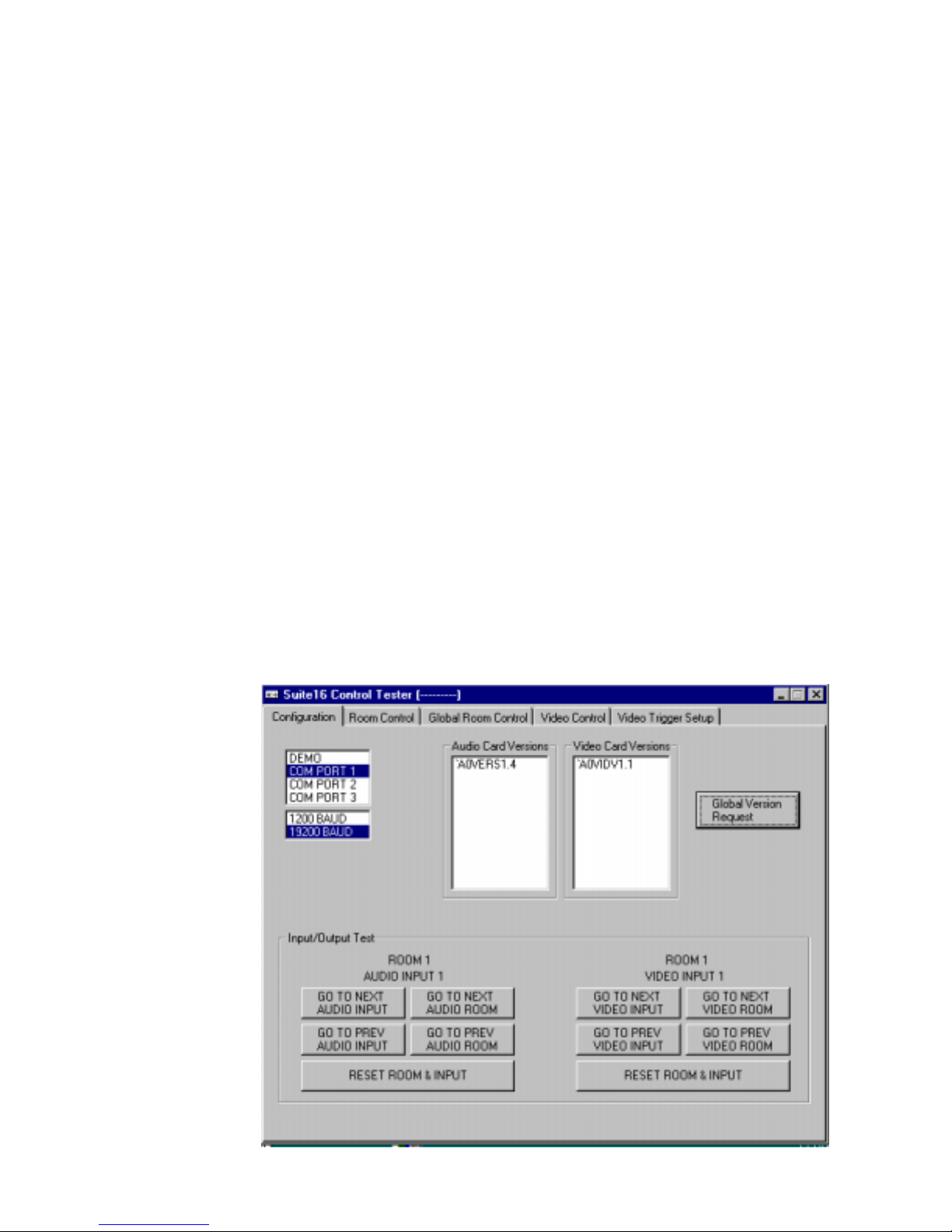
Suite 16 Testing & Program
ADA has developed a fully functional PC program for the Suite-16 System, the Suite-16 Testing & Programming Software. Using this application, you can control a complete Suite-16
System. This program is also ideal for setting up a Suite-16 System, permitting you to make
use of all the system features. As many of these features are set and permanently stored in
the Suite-16, setup is typically a onetime procedure.
Use a straight-through 9-pin RS-232 cable when connecting to your PC or an external
control system.
In order to use the PC software, you need to have your PC connected to the Suite-16. There
are several options available to you. The AVP-16 features both a front panel and rear panel
RS-232 9-pin D connector. These two connectors are in parallel. As such, if another control
system or PC is connected to the rear panel jack, you cannot use the front panel. The same
is true if something were connected to the front panel and you desired to connect your PC to
the rear panel. Only one of these two connectors can be used at any one time. As described
on the previous page, if you are using an external control system and wish to, from time to
time, connect a PC to the front panel jack (for service and setup), you may select to include an
ADA ISO-232 ADA Bus to RS-232 Converter to the system. The ISO-232 can be used for the
external control system while the front (or rear panel) RS-232 port on the AVP-16 can be used
for connection to your PC. If you do not have an ISO-232 and are using an external control
system, disconnect the control system prior to connecting your PC.
ADA strongly suggests using an ISO-232 for external control systems because it provides additional electrical isolation and assists in preventing ground loops.
Configuration Page
The first page will access is the Configuration page. Here you will
need to select your
Com port. The Global
Version Request button
will request the version
numbers of the P-16
and V-16 modules. As
these cards’ programs
are loaded at ADA,
knowing the program
release numbers will be
useful if service issues
arise. This page also
permits you to test audio and video inputs
using the Input/Output
Test area at the bottom
of this page.
- 54 -
Page 56
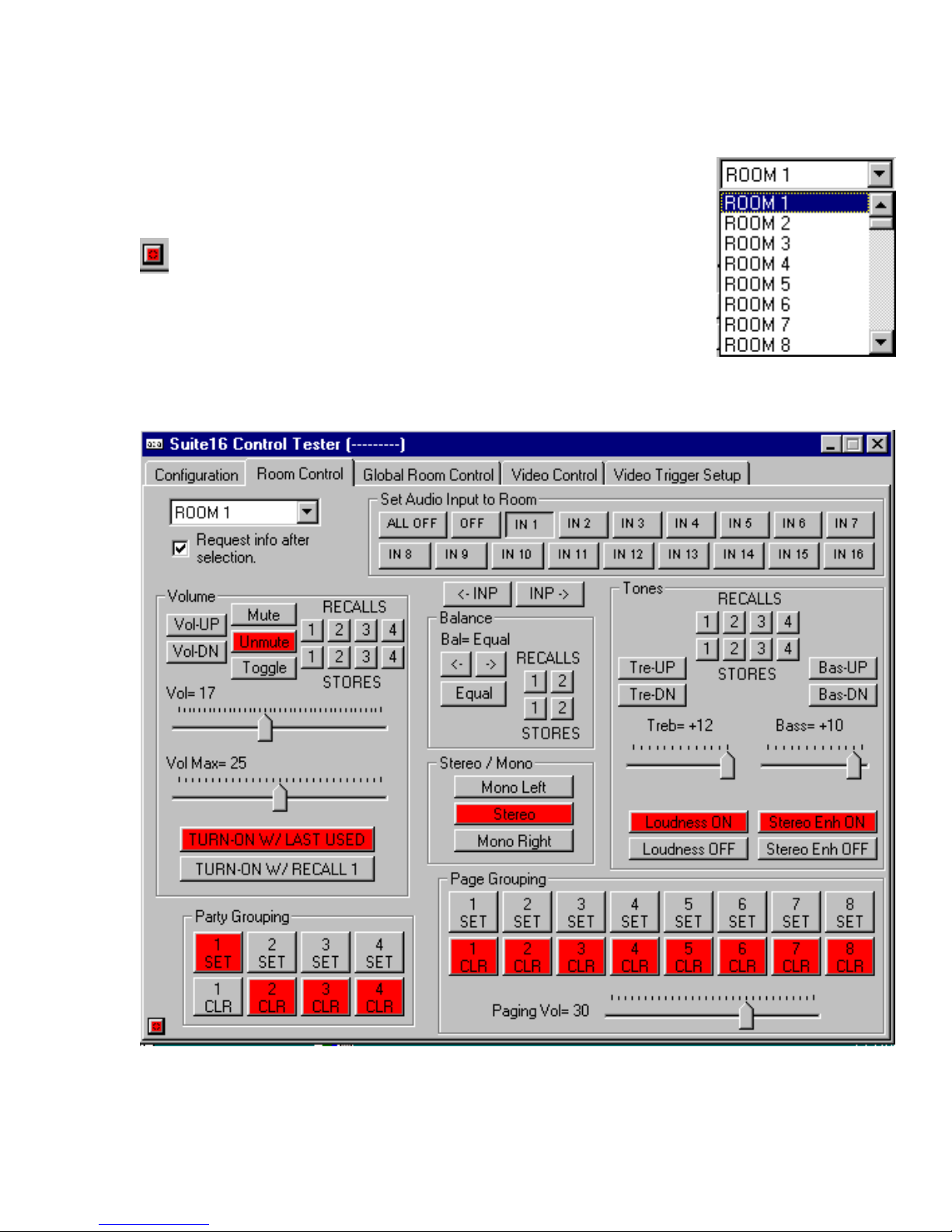
Room Control Page
Under the Room Control tab, you can set and control all of the audio parameters specific to
that room.
Begin by selecting a room number using the pull-down room window.
To update the PC’s display with this room’s status, you will need to
press the little square (orange/red) located in the lower left-hand
corner of this window. The numeric fields for volume, maximum volume, paging volume, treble and bass will populate. Also,
the existing room state will indent regarding all off, room off, or
current audio input as well as turn-on option, stereo-L/R mode, tone
filters on/off, party groupings and page groupings.
The image below details the entire Room Control page. Details for
this page are discussed in the following pages.
- 55 -
Page 57
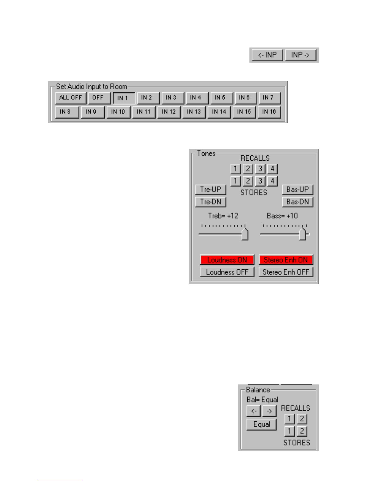
Input Selection
There are several ways to select a source. You can simply use the
input up or input down buttons. You can also directly access inputs
numerically. If a room is off or if the system in all off, those buttons will
be depressed. When an input is selected, the room turns on.
Bass & Treble Control
Bass and Treble are controlled in two ways, there
is the standard up and down commands which will
raise and lower bass and treble levels over a range
from -12 to +12 with 0 being tone control flat. Tones
levels are stepped numerically in two’s, from 0 to 2
to 4 etc. You can also do a bass or treble direct
command which enters a value using the slider control. Much like a touch screen with sliders, the
numeric tone level is jumped to as the slider is released.
Loudness & Stereo Enhancement Filters
There are two additional filters associated with
tones. The loudness filter engages additional bass.
The stereo enhancement filter opens the stereo
imaging of the sound stage.
Tone Presets
There are four tone presets. To store a preset for a specific bass and treble level, set the tone
controls to that level and then press either one of the four tone preset store buttons. To recall
a tone preset, press the corresponding recall button. Please note, that the status of the filters
will also store with the tone presets. If the loudness filter was on and the stereo enhancement
filter was off when preset number 2 was stored, they will return to these settings when preset
number 2 is recalled. Tone preset number 1 is recalled when the zone turns on providing the
zone is set to turn on to recall 1.
Balance Control
Balance is a feature of a speaker channels volume level and the
range swings from Left 40 to Right 40, with the balance set to
Equal when centered between right and left channels. There are
two balance presets. To store a balance preset, set the balance
control to the desired level and then press one of the two store
buttons. To recall the balance level, press the appropriate recall
button. Balance preset number one is recalled when the zone
turns on providing the zone is set to turn on to recall 1.
- 56 -
Page 58
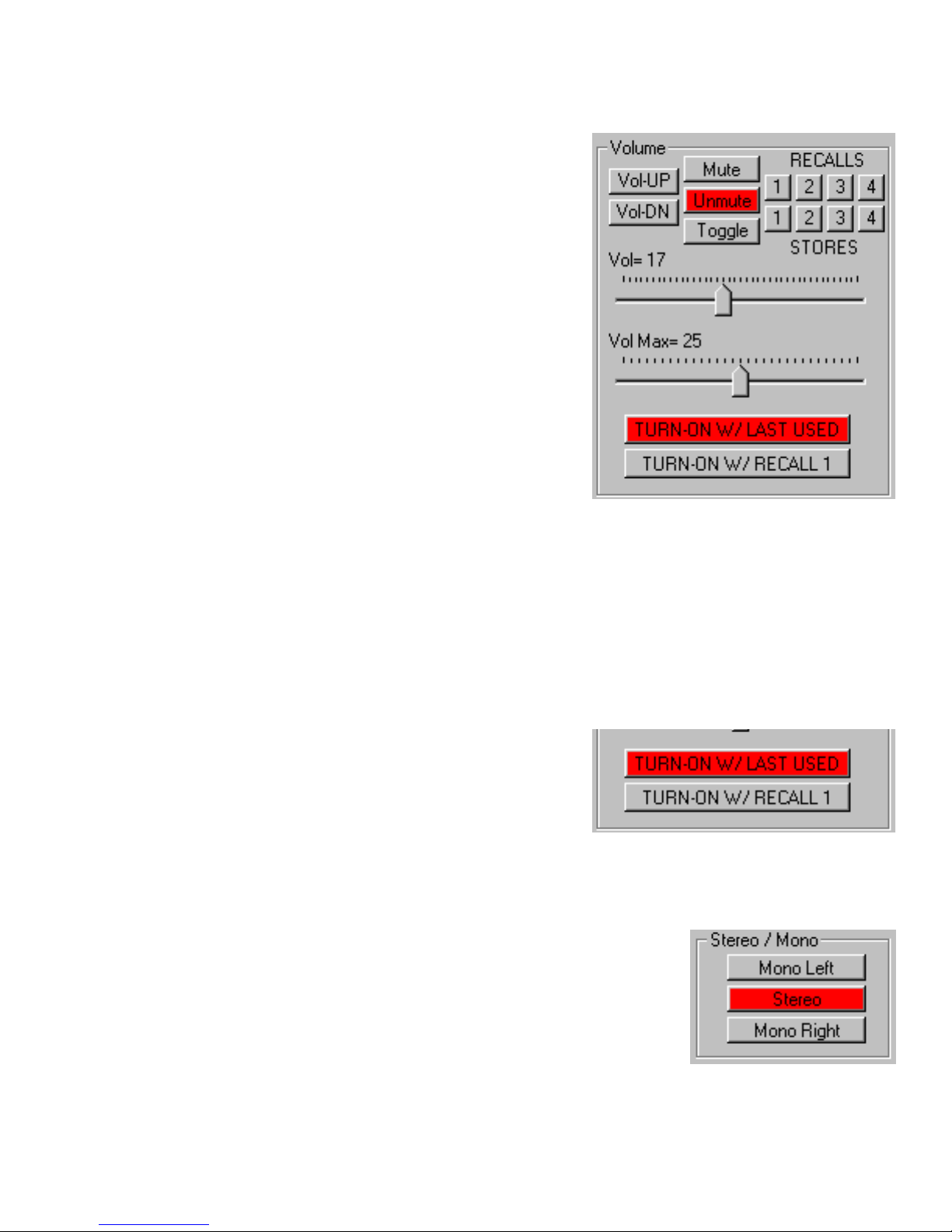
Volume Control
Volume is controlled in two ways, there is the volume
up and down commands which will raise and lower
volume levels over a range with 40 values (0-40). You
can also do a volume direct command which enters a
value using the slider control. Much like a touch screen
with sliders, the numeric volume level, between 0 and
40, is jumped to as the slider is released.
Maximum Volume Level
The maximum volume level is set to prevent the room’s
volume from ever extending beyond the maximum
volume level. To set this level, simply position the slider
at the desired position.
Mute Commands
Again, there are two options for mute. The mute on
command engages mute, while the unmute command
returns sound. Repeated pressing of the toggle button will switch between mute and unmute.
Volume Presets
There are four volume presets. To store a preset for a specific volume level, set the volume to
that level and then press either one of the four volume preset store buttons. To recall a
volume preset, press the corresponding recall button. Volume preset number 1 is recalled
when the zone turns on providing that the zone is set to turn on with recall 1.
Zone Turn On Settings
When a zone turns on, it can be programmed to either turn on to its last used state or to a preset level.
To select the zone to turn on to a preset level, press
the turn-on w/recall 1 button. At this time, all preset
number 1 settings will be recalled when the zone turns
on, including volume, balance, bass, treble and loudness and stereo enhancement filter settings.
Channel Mixing Selector
While you most likely will never have the need to engage a setting
other than stereo, you do have option here to select a particular
channel to play through both right and left preamplifier outputs.
By selecting mono left, both right and left channels will only play
the source signal’s left input. By pressing mono right, both right
and left channels will only play the source signal’s right channel
information. Again, this feature can best be described as useful
when listening to program material with a specific language on
one channel and another language on the left channel. As this is a feature set that is not tied
to any preset, it will be important to return to the stereo setting if either mono setting has been
previously selected.
- 57 -
Page 59
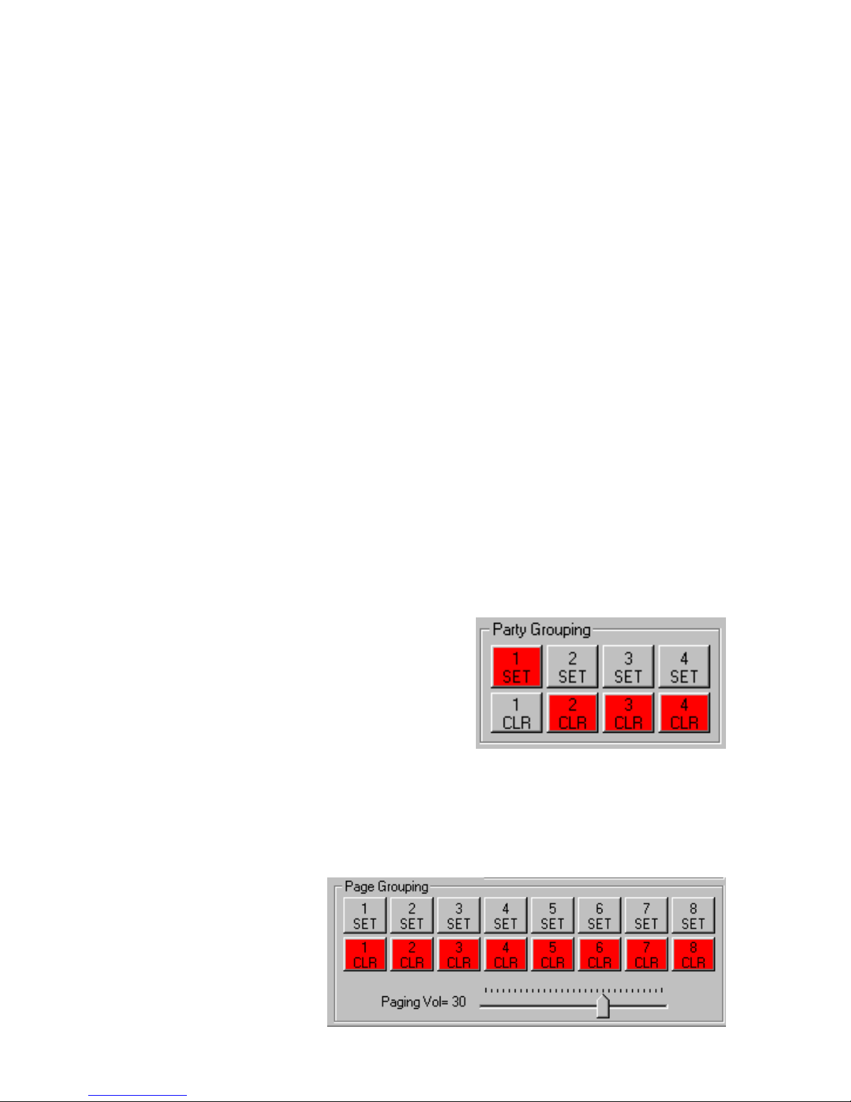
Party Grouping
Party Grouping delivers to the Suite 16 System two functional features. There are a total of
four party groups. Much like a room has command sets for selection of input 1, input 2,...,input 16, each party group also has an input selection command set for input 1, input 2,...,input
16. Just like room 5 has an input selection command for source 8, party group 1 has an input
selection command set for source 8.
With this in mind, we can proceed to understand how to use the party group functions. As
previously mentioned, party grouping has two useful features. The first is the ability for several zones to turn on to a single source with one command. This is useful for entertaining,
hence the name “party groups”. By assigning several rooms to a party group number, when
an input selection is sent for this party group, all rooms on this party group engage to that
source. If rooms are set to turn on to their acoustical preset, then all rooms associated with
this party group, will turn on to the installers preset levels.
The second feature of party grouping can be used for multiple rooms that are architecturally
open to each other. Here, the system can be set up such that when one room turns on to a
source, the other rooms open to each other also turn on to that source. As sources are
switched, these rooms will always track the same source. Because these rooms exist as
independent zones on the Suite 16, they can still have their own acoustical levels and can
turn off independently, but they will always share the same source.
The MC-5000 keypad has a feature set that permit the source buttons, instead of sending out
input commands for a specific room, to send out input commands for a specific party group. If
for example, three rooms: the entry foyer, living room, and dining room, all have a MC-5000
set to party group 2, when FM 2 is selected in the foyer, the other two rooms will also turn on
to FM 2. If later, you change the living room to CD 1, the other areas will also switch to CD 1.
To set a room to track a particular party group, simply
press the appropriate set button while on that room. To
remove a room from that party group, press the clear
button.
Page Grouping
Page grouping is set and cleared on a per room basis much like party grouping. Paging
groups 1-6 are the serially controlled. Paging group 7 is triggered via audio sensing. Paging
group 8 is triggered via low voltage.
Paging Volume Level
The volume level for pages is inde-pendent of the rooms volume level and is set by the slider
control. When a page is initiated, the
room ramps to that volume level, the
tone controls are set to flat, and the
filters are turned off. When the page
is released, the room returns to the
previous levels and input. If the room
was off, it will return to the off state.
- 58 -
Page 60
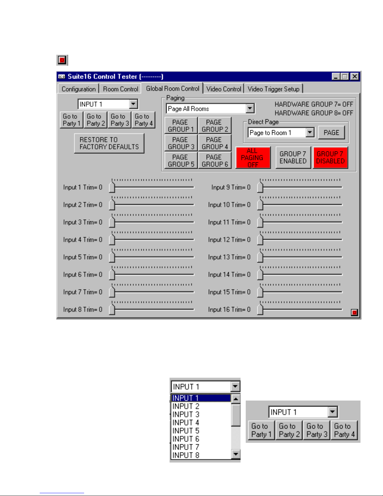
Global Room Control Page
The global room control tab features both party group and paging triggers as well as the input
level trim controls.. The red button in the lower right hand corner is the update informa-
tion request button.
Input Level Trim Adjustment
The trim level adjustment can lower the input of level of a source component. As such, the
sources that play louder than the least loud source, can be balanced off to be as loud as the
least loud source. As such, the least loud source becomes the reference input, where all
other sources are lowered so that they are in balance to the least loud source. As such, when
you change inputs, the volume levels between sources remains the same.
Party Group Testing
To test and/or activate a party
group to a specific input, select
the desired input from the pull
down input window. Then press
the desired party group button.
- 59 -
Page 61
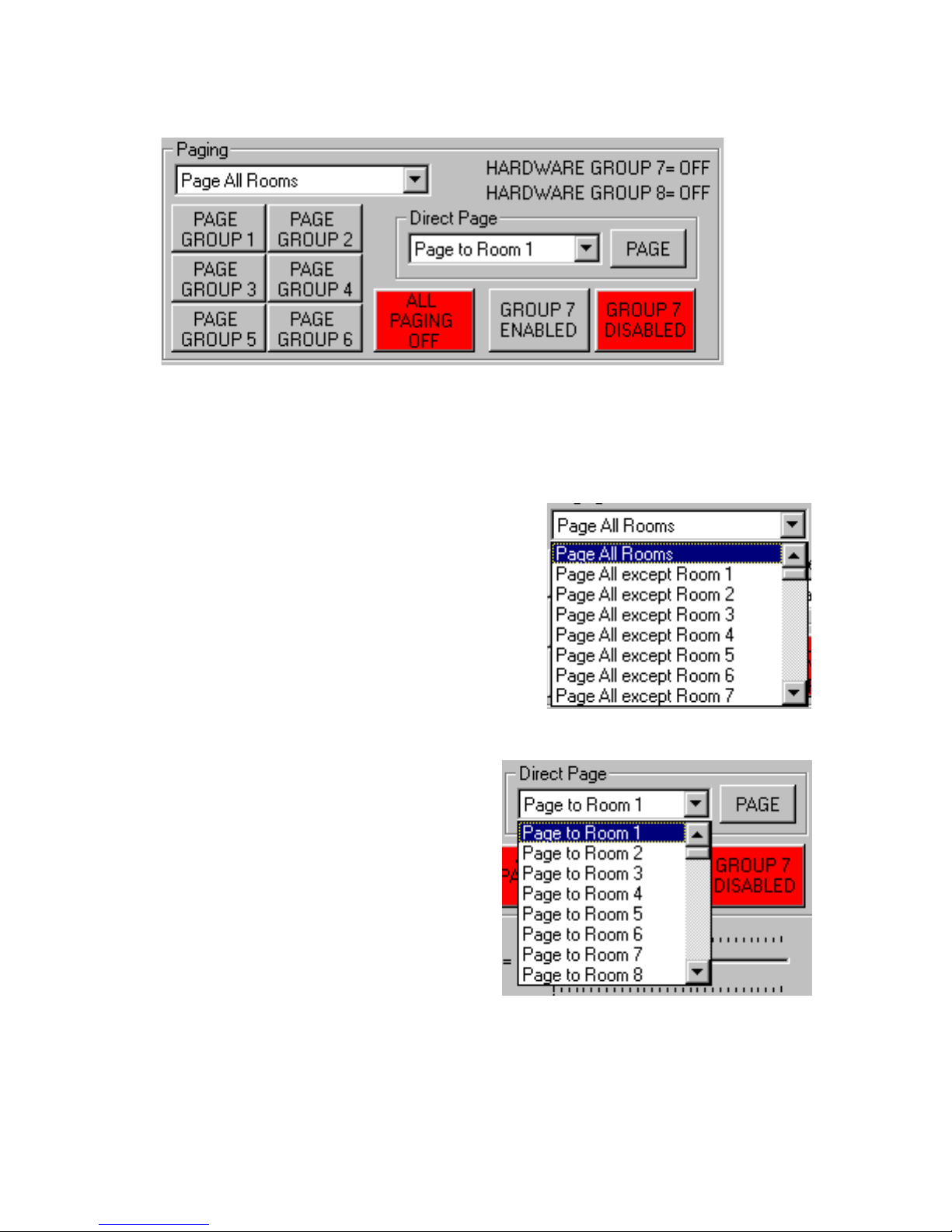
Paging Control
The paging control tab permits you to simulate paging triggers.
The first six triggers are only controlled serially. As such, a control code needs to be issued in
order to activate triggers 1 through 6.
Paging group 7 is the audio sensing trigger. The sensitivity of this trigger is set on the front of
the A-16 module by removing the plexiglass panel. Because a page will always cause the
audio to be sensed, if you desire to defeat this trigger entirely (perhaps because you are only using serial triggers),
this page has an option which permits you to disable paging group 7 entirely.
Paging group 8 is the low voltage trigger paging group,
again hardwired directly to the back of the A-16 module.
When engaging any of the paging groups, you can opt to
remove a room from being paged by selecting the page all
except the desired room number pull down window.
You can also activate paging to a single room on this
page. For direct paging, select the room number and
then press the page button.
It is important to remember that when a page is activated, you must turn paging off before rooms return
to their previous state. Once a page is initiated, it will
remain on until it is turned off. In the case of triggers
7 & 8, the paging turns off when the trigger is removed.
In the case of paging group triggers 1-6 or room to
room paging, you must turn all paging off.
If paging is on, there are two ways to turn paging off. If a room is being paged, selecting an
alternate source input will turn the paging off for just that room. To reset paging for the entire
system other than by issuing a serial control to do so, you will need to reset the system by
turning the master power switch off on the front of the Suite 16.
- 60 -
Page 62
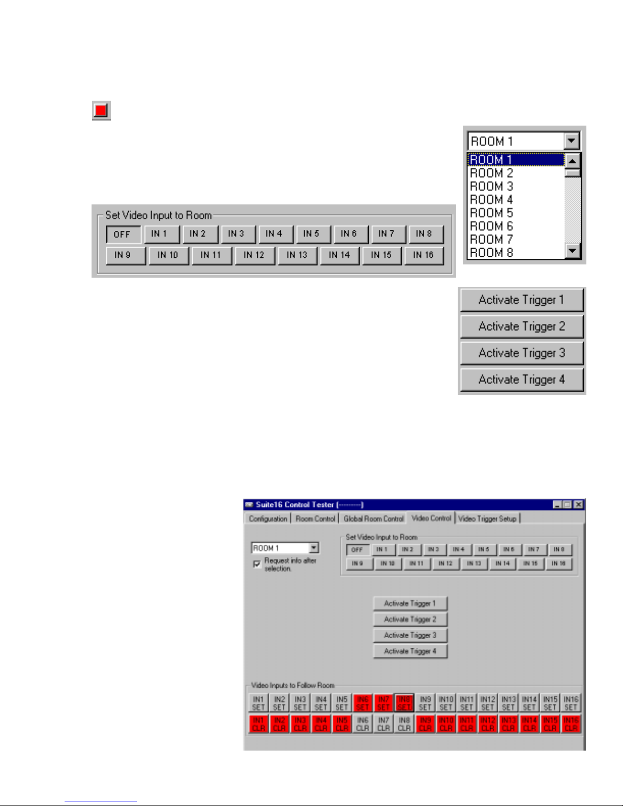
Video Control Page
The video control tab permits control video direct selection, activation of the four video triggers, and also features the settings for video-follow-audio switching. To update this page,
press the red button located in the lower left hand corner.
For direct video switching, select the room number from the pull
down window and then press the desired video input. Even if the
output is set to follow an active audio input, this switching will engage the newly selected input. You can also turn an active video
input off to that room by press the off button.
There are four video triggers which can either be engaged serially,
as on this page, or via low voltage. Setting these triggers will be
discussed later on, but they are activated on this page.
The other options on this page involve setting video inputs to track
audio selections. If an audio input has a video follower, you can set
that input to track that audio selection. This function is also room
specific, such that video follow audio tracking can be different in
various rooms. The reason for this is simple. If a room has no video display of any type
connected to the Suite 16, its room output can be used to drive another video device that is
not room specific. For example, if room 3 physically has no TV, and room 4 has both a TV and
a video capable touch screen, then the room 3 output can be used to drive video to the touch
screen, while the room 4 output can be set to video-follow-audio. When using an open room
output to drive a video display that is not intended to track any room’s audio selections, all
video inputs to follow
rooms must be in the clear
(or off) state. This will permit that room (output) to directly access video without
interruption from other
room audio activities. To
cause a video input to follow its numeric audio
counterpart, press the appropriate set buttons. To
remove this feature, press
the clear button. Remember to activate video-follow-audio tracking for each
room. This is a room by
room specific function, not
a global function.
- 61 -
Page 63
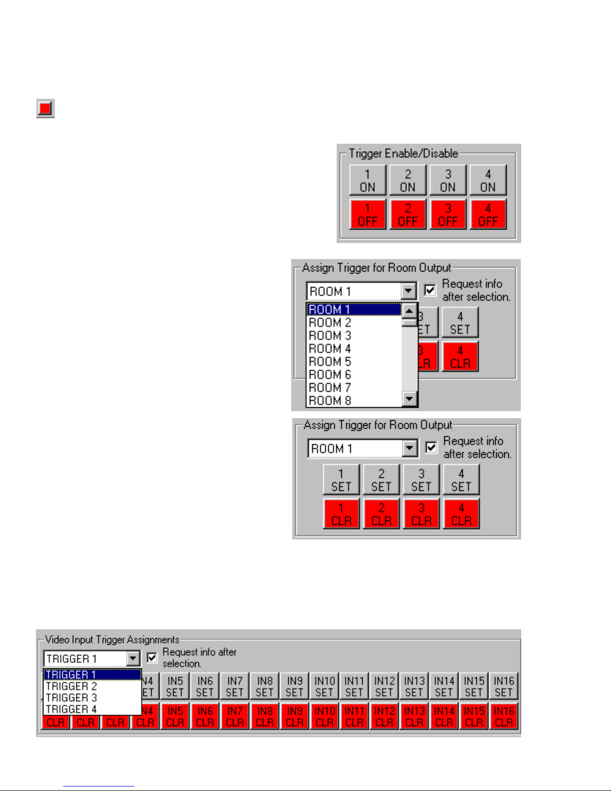
Video Trigger Setup Page
The video trigger setup tab incorporates the feature sets that determine what events occur
when one of the four video triggers is activated. Here, the surveillance feature set of Suite 16
becomes obvious. To update this page, press the red box in the lower left hand corner
of the window.
There are a total of four triggers which can be activated
via serial command sets (as on the previous page) or
low voltage triggers (connected directly to the V-16 module). You can choose to disable any of these four triggers in this page. This will be useful if the system is
already wired for triggers, but you later wish to prevent
a trigger from occurring. Instead of pulling out the rack
to rewire the system, simply disable that trigger completely by turning it off.
To begin we will determine which rooms (or
video outputs) are affected by a video trigger.
We specify outputs because some of the most
useful effects of this feature set revolve around
the ability to use open outputs to drive video
capable touch-screens or closed-circuit TV
monitors. Naturally, this feature also will override video playing on TV, much like the paging
feature overrides audio playing in a room.
To set a room to follow a trigger or several triggers, pull down the room number from the assign trigger for room output section. To set a
room (video output) to activate when a specific
trigger is turned on, press the numeric set number for that trigger. To clear a trigger, press the
clear button.
Now that we know which rooms (video outputs) track which triggers, we can determine what
occurs when a trigger is activated. To start we will discuss the issue of video input trigger
assignments. In this area of the page, select one of the four triggers using the pull down
window. Next, determine which of the 16 video inputs are assigned to that trigger. For example, if video inputs 15 and 16 are open on the V-16, they could have closed circuit TV
cameras connected to them. If in this example, inputs 15 and 16 are the two cameras cover-
- 62 -
Page 64
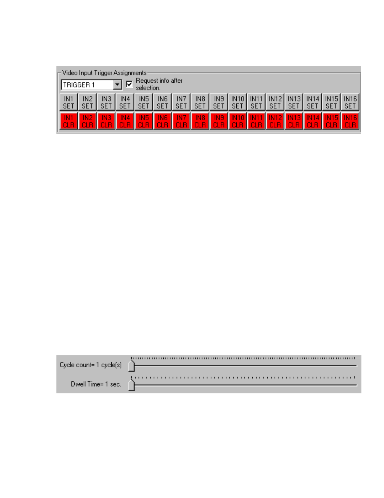
ing the front door, and you want to assign these cameras to trigger number 1, select trigger
number 1 from the pull down window and then set input 15 and 16 by pressing the appropriate
set buttons. To clear these inputs from these triggers, press the clear buttons.
To determine what triggers do when they are activated, Suite 16 features a cycle count and
dwell time setting. These two settings are global in that they will affect all four triggers. If you
change the cycle count or dwell time for one trigger, you will alter the features for the other
triggers. As such, you will want to give some thought into how you set cycle count and dwell
time when using more than one trigger.
Dwell time refers to the length the input is held and is adjustable from a 1 second to 60 second
time frame. Cycle count refers to the number of cycles that are repeated before the trigger is
released. Cycle count goes from one cycle to 99 cycles. As such, the shortest time interval
can be 1 second (dwell time = 1 second & cycle count = 1) all the way up to 99 minutes (dwell
time = 60 seconds & cycle count = 99). In the example previously used, with two cameras
covering the front door, when the front doorbell is pressed, trigger 1 engages. If the dwell time
is set to 3 seconds and the cycle count is set to 4, then the first camera is displayed for three
seconds, then the second camera for three seconds. This sequence will repeat three more
times and then the trigger will turn off (24 seconds total time - 3x4 + 3x4).
If trigger number two has just one camera by the front gate which is activated with an electronic eye, then when trigger number two is engaged, the gate camera will be held for a period
of 12 seconds (3 second dwell time x 4 cycles). Even though the Suite 16 is cycling, the
image for a single input on a trigger is held steady without flutter.
To set the cycle count and dwell time, use the sliders bearing in mind that these features are
global and will affect all four triggers.
- 63 -
Page 65

Suite 16 Serial Protocol V1.4 Explanation
PURPOSE:
This document explains the serial data code structure and operation of the Suite 16 MultiRoom Preamplifier. This document is preliminary and is for Suite 16 Audio card with version
1.4 software. All content subject to change.
DISCUSSION:
The Suite 16 Multi-Room Preamplifier is serial controlled at 19200 baud or 1200 baud. The
10 character command structure is as follows:
START CHARACTER ACTION FUNCTION ROOM#/GLOBAL <CR>
Example ‘ S or G AD01 R01 <CR>
The above example demonstrates how you would set room 1 to analog input 1. The start
character must always be a ‘ called an accent grave, located on the key next to the 1 key on
a standard QWERTY keyboard. All letters used in a 10 character string must be upper case.
The end of the string must always end in a carriage return or “ENTER” key. The second
character is “S” for set when performing a function. When updates about system status are
requested this character will be a “G” for get. The third through sixth characters are the function code. Referring to the excel sheet you can look up the various functions that the preamplifier can perform. In some cases, like the volume direct command, some of the characters
are a value entered into the system. The seventh through ninth characters are for telling the
system that the command is for a specific room or a global function. Like the function code,
some of the characters can be a variable for certain functions.
After there is a power failure and power is restored, the system will return to the last active
settings for every room including whether the room was on or off, tone controls, volume, input
trim, balance and input selected. The exception being if any page mode had been activated
by serial command it will be cancelled. If a page mode is being activated manually or by auto
audio level detection then the page will be active on power up.
The feedback response is an 11 character string
START Acknowledge PLACE FUNCTION ROOM or
CHAR HOLDER GLOBAL
Example ‘ A X AD01 R01 <cr>
The “A” is for acknowledge and is in every feedback response
The “X” is a placeholder but is used only for feedback in the volume, tone and balance
presets
- 64 -
Page 66

DESCRIPTION OF COMMANDS:
ALL OFF
Powers down all rooms, amplifiers and source equipment; a global shutdown
EXAMPLE ‘SALOFG00<cr> shut system down
Feedback ‘AXALOFG00<cr>
Feedback Request ‘GALOFG00<cr>
Feedback ‘AXALOFG00<cr> or
‘ASYSONG00
INPUT UP
Each input up command will advance to the next numbered audio input for a given room.
When the input is 16 and the input up command is requested the system will roll over to input
1 and continue to advance to the next highest input. If the room was powered down it will turn
on with the previous input before it was powered down.
EXAMPLE ‘SINUPR01<cr> step input up by one
Feedback ‘AXAD02R01<CR> feedback reflects current input for
selected room
Feedback Request ‘GINUPR01<cr>
Feedback ‘AXRMOFR01<cr> room 1 is off
Or ‘AXAD##R01<cr> current input selected for room 1
Or ‘AXALOFG00<cr> system is off
INPUT DOWN
Each input down command will decrement to the next numbered audio input for a given room.
When the input is 1 and the input down command is requested the system will roll over to
input 16 and continue to decrement to the next lowest input. If the room was powered down it
will turn on with the previous input before it was powered down.
EXAMPLE ‘SINDNR01<cr>
Feedback ‘AXAD02R01<CR> feedback reflects current input for
selected room
Feedback Request ‘GINDNR01<cr>
Feedback ‘AXRMOFR01<cr> room 1 is off
Or ‘AXAD##R01<cr> current input selected for room 1
Or ‘AXALOFG00<cr> system is off
- 65 -
Page 67

INPUT 1-INPUT 16
Directly selects one of the 16 discreet audio inputs for a given room. If the room was off the
room will now be turned on and its associated amplifier and source equipment will be activated.
EXAMPLE ‘SAD01R01<cr> select audio input 1 for room 1
Feedback ‘AXAD01R01<cr>
Feedback Request ‘GAD##R01<cr>
Feedback ‘AXRMOFR01<cr> room 1 is off
Or ‘AXAD##R01<cr> current input selected for room 1
Or ‘AXALOFG00<cr> system is off
MUTE TOGGLE
Each mute toggle command will toggle that room between mute and unmute. No function
when room is off. Feedback request allowed when room is off.
EXAMPLE ‘SMTOGR01<cr> toggle mute in room 1
Feedback Request ‘GMTOGR01<cr>
Feedback ‘AXMTONR01<cr> room 1 mute is on
Or ‘AXMTOFR01<cr> room 1 mute is off
MUTE ON
Mutes the audio signal for the selected room. No function when room is off. Feedback request
allowed when room is off.
EXAMPLE ‘SMTONR01<cr> mute room 1
Feedback ‘AXMTONR01<cr> room 1 mute is on
Feedback request ‘GMTONR01<cr>
Feedback ‘AXMTONR01<cr> room 1 mute is on
Or ‘AXMTOFR01<cr> room 1 mute is off
MUTE OFF
Unmutes the audio signal for the selected room. No function when room is off. Feedback
request allowed when room is off.
EXAMPLE ‘SMTOFR01<cr> unmute room 1
Feedback ‘AXMTOFR01<cr> room 1 mute is on
Feedback request ‘GMTOFR01<cr>
Feedback ‘AXMTONR01<cr> room 1 mute is on
Or ‘AXMTOFR01<cr> room 1 mute is off
- 66 -
Page 68

ROOM OFF
Shuts down the selected room. If it is the only room on in the system the response will be all
off.
EXAMPLE ‘SRMOFR01<cr> turn off room 1
Feedback ‘AXRMOFR01<cr> or room 1 is off
‘AXALOFG00 all off when last room turned off
Feedback Request ‘GRMOFR01<cr>
Feedback ‘AXRMOFR01<cr> room 1 is off
Or ‘AXAD##R01<cr> current input selected for room 1
Or ‘AXALOFG00<cr> system is off
VOLUME UP
Advances the volume by 1 up to a maximum of 40 for a given room. If the volume has
reached 40 any additional commands will result in a volume level of 40. No function when
room is off. Feedback request allowed when room is off.
EXAMPLE ‘SVLUPR01<cr> increment volume up by 1 in room 1
Feedback ‘AXV###R01<cr> current volume set in room 1
Feedback Request ‘GVLUPR01<cr>
Feedback ‘AXV###R01<cr> current volume set in room 1
VOLUME DOWN
Decrements the volume by 1 to a minimum of 0 for a given room. If the volume has reached
0 and additional commands will result in a volume level of 0. No function when room is off.
Feedback request allowed when room is off.
EXAMPLE ‘SVLDNR01<cr> decrement volume by 1 in room 1
Feedback ‘AXV###R01<cr> current volume set in room 1
Feedback Request ‘GVLDNR01<cr>
Feedback ‘AXV###R01<cr> current volume set in room 1
VOLUME DIRECT
Allows you to go directly to a volume level for a given room. The function command is in the
form of V### where ###is a number from 000 to 040. No function when room is off. Feedback
request allowed when room is off.
EXAMPLE ‘SV040R01<cr> set maximum volume in room 1
Feedback ‘AXV040R01<cr> volume is set to maximum in room 1
Feedback Request ‘GV###R01<cr>
Feedback ‘AXV###R01 current volume value for room 1
- 67 -
Page 69

BASS UP
Advances bass by 2dB for a given room. The range of Bass is +12dB to -12dB incremented
by 2dB. When set to 0dB bass is flat. No function when room is off. Feedback request allowed when room is off.
EXAMPLE ‘SBSUPR01<cr> increment bass up by one step in room 1
Feedback ‘AXB###R01<cr> current bass value for room 1
(-12,-10,-08,-06,-04,-02,000,+02,+04,+06,+08,+10,+12)
Request Feedback ‘GBSUPR01<cr>
Feedback ‘AXB###R01<cr> current bass value for room 1
BASS DOWN
Decrements bass by 2dB for a given room. No function when room is off. Feedback request
allowed when room is off.
EXAMPLE ‘SBSDNR01<cr> decrement bass by one step in room 1
Feedback ‘AXB###R01<cr> current bass value for room 1
Request Feedback ‘GBSDNR01<cr>
Feedback ‘AXB###R01<cr> current bass value for room 1
BASS DIRECT
Allows you to go directly to a bass value for a given room. No function when room is off.
Feedback request allowed when room is off.
The command is in the form of B### where ### can be any of 13 values and is signed. The
possible combinations are:
B-12,B-10,B-08 B-06,B-04,B-02,B000, B+02,B+04,B+06,B+08,B+10,B+12
EXAMPLE ‘SB+12R01<cr> set maximum bass in room 1
Feedback ‘AXB+12R01<cr> current bass value for room 1
Request Feedback ‘GB###R01<cr>
Feedback ‘AXB###R01<cr> current bass value for room 1
TREBLE UP
Advances treble by 2dB for a given room. No function when room is off. Feedback request
allowed when room is off.
The range of treble is +12dB to -12dB. When set to 0dB treble is flat.
EXAMPLE ‘STRUPR01<cr> increment treble up one step
Feedback ‘AXT###R01<cr> current treble value for room 1
(-12,-10,-08,-06,-04,-02,000,+02,+04,+06,+08,+10,+12)
Request Feedback ‘GTRUPR01<cr>
Feedback ‘AXT###R01<cr> current treble value for room 1
- 68 -
Page 70

TREBLE DOWN
Decrements treble by 2dB for a given room. No function when room is off. Feedback request
allowed when room is off.
EXAMPLE ‘STRDNR01<cr> decrement treble by 1 step in room 1
Feedback ‘AXT###R01<cr> current treble value for room 1
Request Feedback ‘GTRDNR01<cr>
Feedback ‘AXT###R01<cr> current treble value for room 1
TREBLE DIRECT
Allows you to go directly to a treble value for a given room. No function when room is off.
Feedback request allowed when room is off.
The command is in the form of T### where ### can be any of 13 values and is signed. The
possible combinations are:
T-12,T-10,T-08 T-06,T-04,T-02,T000, T+02,T+04,T+06,T+08,T+10,T+12
EXAMPLE ‘ST+12R01<cr> set maximum treble in room 1
Feedback ‘AXT+12R01<cr> current treble value for room 1
Request Feedback ‘GT###R01<cr>
Feedback ‘AXT###R01<cr> current treble value for room 1
TONE STORE 1-4
Allows you to store 4 preset combinations of bass, treble, loudness contour and stereo enhance for a given room. This command will store the current active tone values. No function
when room is off. Feedback request allowed when room is off.
EXAMPLE ‘STNS1R01<cr> store current room 1 tone settings in
tone recall 1
Feedback ‘AB1###R01<cr> tone preset 1 bass value
‘AT1###R01<cr> tone preset 1 treble value
‘ALD1OFR01<cr> or ‘ALD1ONR01<cr> tone preset 1 loudness off or on
‘AST1OFR01<cr> or ‘AST1ONR01<cr> tone preset for stereo enhance off/on
Feedback Request ‘GTNS1R01<cr>
Feedback ‘AB1###R01<cr> tone preset 1 bass value
‘AT1###R01<cr> tone preset 1 treble value
‘ALD1OFR01<cr> or ‘ALD1ONR01<cr> tone preset 1 loudness off or on
‘AST1OFR01<cr> or ‘AST1ONR01<cr> tone preset for stereo enhance off/on
- 69 -
Page 71

TONE RECALL 1-4
Allows you to recall 4 pre-stored combinations of bass, treble, loudness contour and stereo
enhance. No function when room is off. Feedback request allowed when room is off.
EXAMPLE ‘STNR1R01<cr> recall tone 1 settings for room 1
Feedback ‘AXB###R01<cr> current bass value for room 1
‘AXT###R01<cr> current treble value for room 1
‘AXLDONR01<cr> or
‘AXLDOFR01<cr> current loudness for room 1
‘AXSEONR01<cr> or
‘AXSEOFR01 current stereo enhance for room 1
Feedback Request ‘GTNR1R01<cr>
Feedback ‘AB1###R01<cr> tone preset 1 bass value
‘AT1###R01<cr> tone preset 1 treble value
‘ALD1OFR01<cr> or ‘ALD1ONR01<cr> tone preset 1 loudness off or on
‘AST1OFR01<cr> or ‘AST1ONR01<cr> tone preset for stereo enhance off/on
VOLUME STORE 1-4
Allows you store 4 preset volume levels for a given room. The current volume level active
when command is initiated will be stored. No function when room is off. Feedback request
allowed when room is off.
EXAMPLE ‘SVLS1R01<cr> store current room 1 volume in volume recall 1
Feedback ‘AV1###R01<cr> volume preset 1 stored volume value
Feedback Request ‘GVLS1R01<cr>
Feedback ‘AV1###R01<cr> volume preset 1 stored volume value
VOLUME RECALL 1-4
Allows you to recall 4 pre-stored volume levels for a given room. No function when room is off.
Feedback request allowed when room is off.
EXAMPLE ‘SVLR1R01<cr> make volume in volume recall 1 active
for room 1
Feedback ‘AXV###R01<cr> current volume value for room 1
Feedback Request ‘GVLR1R01<cr>
Feedback ‘AV1###R01<cr> volume stored in volume preset 1
LOUDNESS CONTOUR ON
Turns on loudness contour mode for a given room. No function when room is off. Feedback
request allowed when room is off.
EXAMPLE ‘SLDONR01<cr> turn on loudness contour for room 1
Feedback ‘AXLDONR01<cr>
Feedback Request ‘GLDONR01<cr>
Feedback ‘AXLDONR01<cr> or ‘AXLDOFR01<cr> Loudness contour on or off in room 1
- 70 -
Page 72

LOUDNESS CONTOUR OFF
Turns off loudness contour mode for a given room. No function when room is off. Feedback
request allowed when room is off.
EXAMPLE ‘SLDOFR01<cr> turn off loudness contour for room 1
Feedback ‘AXLDOFR01<cr>
Feedback Request ‘GLDOFR01<cr>
Feedback ‘AXLDONR01<cr> or ‘AXLDOFR01<cr> Loudness contour on or off in room 1
STEREO ENHANCE ON
Turns on stereo enhance mode for a given room. No function when room is off. Feedback
request allowed when room is off.
EXAMPLE ‘SSEONR01<cr> turn on stereo enhance mode for room 1
Feedback ‘AXSEONR01<cr>
Feedback Request ‘GSEONR01<cr>
Feedback ‘AXSEONR01<cr> or ‘AXSEOFR01<cr> Loudness contour on or off in room 1
STEREO ENHANCE OFF
Turns off stereo enhance mode for a given room. No function when room is off. Feedback
request allowed when room is off.
EXAMPLE ‘SSEOFR01<cr> turn off stereo enhance mode for room 1
Feedback ‘AXSEOFR01<cr>
Feedback Request ‘GSEOFR01<cr>
Feedback ‘AXSEONR01<cr> or ‘AXSEOFR01<cr> Loudness contour on or off in room 1
STEREO
Places a given room in Stereo mode. No function when room is off. Feedback request allowed when room is off.
EXAMPLE ‘SSTROR01<cr> place room 1 in stereo mode
Feedback ‘AXSTROR01<cr>
Feedback Request ‘GSTROR01<cr>
Feedback ‘AXSTROR01<cr> or room 1 in stereo mode
‘AXMINLR01<cr> orroom 1 in mono input left mode
‘AXMINRR01<cr> room 1 in mono input right mode
MONO INPUT LEFT
Selects left source input to be routed to left and right speakers for a given room
No function when room is off. Feedback request allowed when room is off.
EXAMPLE ‘SMINLR01<cr> left input to left and right speakers in room 1
Feedback ‘AXMINLR01<cr>
Feedback Request ‘GMINLR01<cr>
Feedback ‘AXSTROR01<cr> or room 1 in stereo mode
‘AXMINLR01<cr> or room 1 in mono input left mode
‘AXMINRR01<cr> room 1 in mono input right mode
- 71 -
Page 73

MONO INPUT RIGHT
Selects right source input to be routed to left and right speakers for a given room
No function when room is off. Feedback request allowed when room is off.
EXAMPLE ‘SMINRR01<cr> right input to left and right speakers in room 1
Feedback ‘AXMINRR01<cr>
Feedback Request ‘GMINRR01<cr>
Feedback ‘AXSTROR01<cr> or room 1 in stereo mode
‘AXMINLR01<cr> or room 1 in mono input left mode
‘AXMINRR01<cr> room 1 in mono input right mode
BALANCE LEFT
Increment by 1 balance to the left for a given room. No function when room is off. Feedback
request allowed when room is off.
EXAMPLE ‘SBALLR01<cr> increment by 1 balance to the left in room 1
Feedback ‘AXB###R01<cr> current balance value for room 1
(L40/R40/LEQ)
Feedback Request ‘GBALLR01<cr>
Feedback ‘AXB###R01<cr> current balance value in room 1
BALANCE RIGHT
Increment by 1 balance to the right in a given room
No function when room is off. Feedback request allowed when room is off.
EXAMPLE ‘SBALRR01<cr> increment by 1 balance to the right in room 1
Feedback ‘AXB###R01<cr> current balance value for room 1
Feedback Request ‘GBALRR01<cr>
Feedback ‘AXB###R01<cr> current balance value in room 1
BALANCE EQUAL
Sets balance equal for a given room
No function when room is off. Feedback request allowed when room is off.
EXAMPLE ‘SBLEQR01<cr> set balance equal in room 1
Feedback ‘AXBLEQR01<cr>
Feedback Request ‘GBLEQR01<cr>
Feedback ‘AXB###R01 current balance value for room 1
- 72 -
Page 74

BALANCE STORE 1-2
Allows you to store 2 balance settings for a given room. The current active balance setting is
stored. No function when room is off. Feedback request allowed when room is off.
EXAMPLE ‘SBLS1R01<cr> store current room 1 balance setting in
balance recall 1
Feedback ‘A1B###R01<cr>
Feedback request ‘GBLS1R01<cr> request balance store 1 for room 1 or
‘GBLS2R01<cr> request balance store 2 for room 1
Feedback ‘A1B###R01<cr> or balance stored in balance preset 1 for room 1
`A2B###R01<cr> balance stored in balance preset 2 for room 1
BALANCE RECALL 1-2
Allows you to recall 2 pre-stored balance setting for a given room. No function when room is
off. Feedback request allowed when room is off.
EXAMPLE ‘SBLR1R01<cr> make balance recall 1 active for room 1
Feedback ‘AXB###R01<cr> current balance value for room 1
Feedback request ‘GBLR1R01<cr> request balance store 1 for room 1 or
‘GBLR2R01<cr> request balance store 2 for room 1
Feedback ‘A1B###R01<cr> or balance stored in balance preset 1 for room 1
‘A2B###R01<cr> balance stored in balance preset 2 for room 1
INPUT LEVEL TRIM 1-16
This is a global command that allows you to trim louder input sources so they may be at
relatively even volumes with other sources. When properly set any source can be selected
and the volume for that room should not have to be re-adjusted. Every room in the system will
attenuate the source by the value set, if any, with this command. The command structure is
the function code selects which input trim to adjust followed by G for global and the 2 digit trim
value. A trim level set to 00 will cause no attenuation for that input. Each value of trim is about
1.5dB of attenuation.
EXAMPLE ‘SIT01G01<cr> Set input trim 1 for 1.5dB attenuation
‘SIT16G02<cr> Set input trim 16 for 3dB attenuation
‘SIT02G00<cr> Set input trim 2 for no attenuation
Feedback ‘AXIT##G##<cr>
Feedback request ‘GIT##G00<cr>
Feedback ‘AXIT##G##<cr>
- 73 -
Page 75

PARTY SET 1-4
Allows any given room to become a “member” of party 1-4
EXAMPLE ‘SPTS1R01<cr> set room 1 to be a member of party 1
Feedback ‘AXPTS1R01<cr>
Feedback Request ‘GPTS1R01<cr>
Feedback ‘AXPTS1R01<cr> or room 1 is in party 1
‘AXPTC1R01 room 1 is not in party 1
PARTY CLEAR 1-4
Clears a given room from party 1-4
EXAMPLE ‘SPTC1R01<cr> clear room 1 from party 1
Feedback ‘AXPTC1R01<cr>
Feedback Request ‘GPTC1R01<cr>
Feedback ‘AXPTS1R01<cr> or room 1 is in party 1
‘AXPTC1R01 room 1 is not in party 1
PARTY 1-4
The party command is a global function of 4 pre-selected groups of rooms. The room members of each party are turned on and set to the same source input in the command string. The
2 characters after the G specify the input to set the party to in the range 01 to 16.
EXAMPLE ‘SPTY1G01<cr> set all members of party 1 to input 1
Feedbackcurrent room inputs for each room in party ‘AXAD##R##<cr>
PAGING OVERVIEW
The paging function of the preamplifier actually has 9 ways to accomplish paging. There are
8 paging groups any room can become a “member” of. Each room also has a serial command to pre-set a paging level for that room. When a room is paged all balance and tone
controls are nulled and the preset page volume is set. After completion of page, control
resume their setting previous to the page. If the room had been turned off it will turn on for the
page and then turn off again when the page is completed. The first 6 groups use serial
controlled paging. Group 7 is the auto paging mode and is hardware controlled. This is
controlled by an audio level detector. When an audio signal applied to the auto page input
exceeds a predetermined level, all members that are part of group 7 are paged. In the event
of interference or noise inadvertently activating auto page, there is a serial command which
can activate or deactivate the auto page mode. Group 8 is another hardware controlled
paging mode. This is a simple dry contact input that will page members of group 8. The ninth
method of paging is the room to room page. With this command any room can be discretely
paged. Only one page can occur at one time. The method of page activation must also be
used to cancel the page. For example, a manual page by contact closure must be cancelled
by opening the contact. An auto page by audio level activation must be cancelled by the level
being below the trigger threshold. Any serial controlled page must be cancelled by a serial
command. For serial command page groups 1-6, if the room initiating the page is part of the
group, it will be omitted so no audio feedback occurs. Functions are as follows:
- 74 -
Page 76

PAGE VOLUME PRESET
Allows a predetermined paging level to be set for a given room. The command structure is
PV## where ## is the preset page volume 00 to 40
EXAMPLE ‘SPV40R01<cr> set page volume to maximum for room 1
Feedback ‘AXPV40R01<cr>
Feedback Request ‘GPV##R01<cr>
Feedback ‘AXPV##R01<cr> current page volume preset value
PAGE DIRECT (direct page to only one room)
Allows direct paging to a specific room. The room is specified by the 2 characters after the G
in the range of 01 to 96. Must be cancelled by the page off command
EXAMPLE ‘ SPDONG01<cr> page room 1 only
Feedback ‘AXPDONG01<cr>
Feedback Request ‘GPDONG00<cr>
Feedback ‘AXP#O#G00<cr> current paging mode
PAGE OFF
This is a global command used to turn off any serial page mode.
EXAMPLE ‘SPGOFG00<cr>
Feedback ‘AXPGOFG00<cr>
Feedback Request ‘GPGOFG00<cr>
Feedback ‘AXP#O#G00<cr> current paging mode
PAGE ENABLE GROUP 1-8
Allows any room to become a “member” of any paging group 1-8
EXAMPLE ‘SPGS1R01<cr> make room 1 a member of paging group 1
Feedback ‘AXPGS1R01<cr>
Feedback Request ‘GPGS#R##<cr>
Feedback ‘AXPGS#R##<cr> page for # group set for room ## or
‘AXPGC#R##<cr> page for # group not set for room ##
PAGE DISABLE GROUP 1-8
Clears any room from any paging group 1-8
EXAMPLE‘SPGC1R01<cr>clear room 1 from paging group 1
Feedback ‘AXPGC1R01<cr>
Feedback Request ‘GPGC#R##<cr>
Feedback ‘AXPGS#R##<cr> page for # group set for room ## or
‘AXPGC#R##<cr> page for # group not set for room ##
- 75 -
Page 77

PAGE GROUP 1-6
Serial controlled paging of any group 1-6. Must be followed by the page off command when
page completed. For audio feedback prevention, include the room number after the G to
temporarily exclude it from the group.
EXAMPLE ‘SP#ONG00<cr> or page a group where # = 1 to 6
‘SP#ONG30<cr> page but exclude room 30
Feedback ‘AXP#ONG00>cr
Feedback Request ‘GP#ONG00<cr>
Feedback ‘AXP#ONG00<cr> or current active page mode
‘AXPGOFG00<cr> all page modes off
AUTO PAGE ON
Turns on the audio level detector for group 7. This is a global command.
EXAMPLE ‘SPAONG00<cr> make auto paging active
Feedback ‘AXPAONG00<cr>
Feedback Request ‘GPAONG00<cr>
Feedback ‘AXPAONG00<cr> or
‘AXPAOFG00<cr>
AUTO PAGE OFF
Turns off audio level detector for group 7 and cancels any page mode. This is a global
command
EXAMPLE ‘SPAOFG00<cr> make auto paging inactive
Feedback ‘AXPAOFG00<cr> or
‘AXPGOFG00<cr>
F
eedback Request ‘GPAOFG00<cr>
Feedback ‘AXPAONG00<cr> or
AXPAOFG00<cr>
AUTO PAGE (aka group 7)
Audio level detection activated page. When audio exceeds a predetermined trigger threshold
page will activate for all rooms that are members of group 7. Paging is complete when audio
is below the trigger threshold. This is a hardware controlled feature. It must be enabled using
the auto page on command.
Feedbackwhen activated ‘AXP7ONG00<cr>
When deactivated ‘AXPGOFG00<cr>
- 76 -
Page 78

MANUAL PAGE (aka group 8)
Contact closure controlled page. All members of group 8 are paged. When contacts are
released paging is complete.
Feedbackwhen activated ‘AXP8ONG00<cr>
When deactivated ‘AXPGOFG00<cr>
MAXIMUM ALLOWABLE VOLUME
Allows you to set a maximum allowable volume level per room. The command is in the form
of MV## where ## is the allowable level 10 to 40.
EXAMPLE ‘SMV40R01<cr> set maximum volume to 40 for room 1
Feedback ‘AXMV40R01<cr>
Feedback Request ‘GMV##R##
Feedback ‘AXMV##R##
ROOM TURN ON WITH LAST USED VOLUME, TONE, BALANCE
Room will turn on and use previous volume, bass, treble, stereo enhance, loudness contour
and balance settings.
EXAMPLE ‘SVPOFR01<cr> use previous settings for tone,
balance and volume in room 1
Feedback ‘AXVPOFR01<cr>
Feedback Request ‘GVPOFR01<cr>
Feedback ‘AXVPONR01<cr> or
‘AXVPOFR01<cr>
ROOM TURN ON WITH VOLUME, TONE AND BALANCE IN PRESET 1
Room will turn on using volume, bass, treble, stereo enhance, loudness contour and balance
stored in volume preset 1, tone preset 1 and balance preset 1.
EXAMPLE ‘SVPONR01<cr> use preset 1 for tone, balance and volume
Feedback ‘AXVPONR01<cr>
Feedback Request ‘GVPONR01<cr>
Feedback ‘AXVPONR01<cr> or
‘AXVPOFR01<cr>
VERSION REQUEST
This is a global command which will indicate the software version of each card. All audio
cards in the system will respond sequentially.
EXAMPLE Feedback Request ‘GVERSG00<cr>
Feedback ‘A0VERS1.4<cr> card 0 has version 1.4 software
‘A1VERS1.4<cr> card 1 has version 1.4 software
- 77 -
Page 79

RESET TO FACTORY DEFAULT VALUES
Resets all parameters to factory default values. All volumes and volume presets are set to
half, bass and treble set flat, balance and balance presets set to equal, stereo enhance off,
loudness contour off, stereo mode on, mute off, all rooms off, all input trims 0, all page groups
cleared, all parties cleared, all tone presets, bass and treble set flat, stereo enhance off,
loudness contour off, auto page off, maximum volume per room set to 40, page volume per
room set to 30, auto page mode off, power up on last room parameters.
EXAMPLE ‘SFDEFG00<cr> reset unit to factory default values
Feedback ‘AXFDEFG00<cr>
UPDATE ALL ROOM PARAMETERS
This is a global command which will feedback all parameters of every room in the system and
also global parameters . This command can be requested only.
EXAMPLE ‘GALRMG00<cr>
Feedback ‘AXPAO#G00<CR> auto page on/off
‘AXIT01G##<CR> input trim 1
‘AXIT02G##<CR> input trim 2
‘AXIT03G##<CR> input trim 3
‘AXIT04G##<CR> input trim 4
‘AXIT05G##<CR> input trim 5
‘AXIT06G##<CR> input trim 6
‘AXIT07G##<CR> input trim 7
‘AXIT08G##<CR> input trim 8
‘AXIT09G##<CR> input trim 9
‘AXIT10G##<CR> input trim 10
‘AXIT11G##<CR> input trim 11
‘AXIT12G##<CR> input trim 12
‘AXIT13G##<CR> input trim 13
‘AXIT14G##<CR> input trim 14
‘AXIT15G##<CR> input trim 15
‘AXIT16G##<CR> input trim 16
and then same feedback as update room for each room
- 78 -
Page 80

UPDATE ALL ROOM CONTROLS
This is an abridged request that only replies with certain room parameters for all rooms as
follows:
EXAMPLE ‘GALRCG00<cr>
Feedback *this feedback sequence is repeated for each room
‘AXV###R##<cr> volume
‘AXB###R##<cr> bass
‘AXT###R##<cr> treble
‘AXB###R##<cr> balance
‘AX####R##<cr> current input or room off or all off
‘AXVPO#R##<cr> volume preset on/off
‘AXMV##R##<cr> max volume
‘AXMTO#R##<cr> mute on or off
‘AX ####R##<cr> stereo or mono in L or mono in R
‘AXLDO#R##<cr> loudness contour on/off
‘AXSEO#R##<cr> stereo enhance on/off
UPDATE A SINGLE ROOM CONTROL
This is like the Update All Room Controls command but replies with information for a single
room.
EXAMPLE ‘GRCONR01<cr>
Feedback ‘AXV###R01<cr> volume
‘AXB###R01<cr> bass
‘AXT###R01<cr> treble
‘AXB###R01<cr> balance
‘AX####R01<cr> current input or room off or all off
‘AXVPO#R01<cr> volume preset on/off
‘AXMV##R01<cr> max volume
‘AXMTO#R01<cr> mute on or off
‘AX ####R01<cr> stereo or mono in L or mono in R
‘AXLDO#R01<cr> loudness contour on/off
‘AXSEO#R01<cr> stereo enhance on/off
UPDATE ROOM
All parameters for any single room
EXAMPLE ‘GROOMR##<cr>
Feedback ‘AXV###R01<cr> volume
‘AXB###R01<cr> bass
‘AXT###R01<cr> treble
‘AXB###R01<cr> balance
- 79 -
Page 81

‘AX####R01<cr> current input or room off or all off
‘AXVPO#R01<cr> volume preset on/off
‘AXMV##R01<cr> max volume
‘AXMTO#R01<cr> mute on or off
‘AX ####R01<cr> stereo or mono in L or mono in R
‘AXLDO#R01<cr> loudness contour on/off
‘AXSEO#R01<cr> stereo enhance on/off
‘AV1###R01<cr> volume preset 1
‘AV2###R01<cr> volume preset 2
‘AV3###R01<cr> volume preset 3
‘AV4###R01<cr> volume preset 4
‘A1B###R01<cr> balance preset 1
‘A2B###R01<cr> balance preset 2
‘AB1###R01<cr> tone preset 1 bass value
‘AT1###R01<cr> tone preset 1 treble value
‘ALD1OFR01<cr> or ‘ALD2ONR01<cr> tone preset 1 loudness off or on
‘ASE1OFR01<cr> or ‘AST2ONR01<cr> tone preset 1 for stereo enhance off/on
‘AB2###R01<cr> tone preset 2 bass value
‘AT2###R01<cr> tone preset 2 treble value
‘ALD2OFR01<cr> or ‘ALD2ONR01<cr> tone preset 2 loudness off or on
‘ASE2OFR01<cr> or ‘AST2ONR01<cr> tone preset 2 for stereo enhance off/on
‘AB3###R01<cr> tone preset 3 bass value
‘AT3###R01<cr> tone preset 3 treble value
‘ALD3OFR01<cr> or ‘ALD2ONR01<cr> tone preset 3 loudness off or on
‘ASE3OFR01<cr> or ‘AST2ONR01<cr> tone preset 3 for stereo enhance off/on
‘AB4###R01<cr> tone preset 4 bass value
‘AT4###R01<cr> tone preset 4 treble value
‘ALD4OFR01<cr> or ‘ALD2ONR01<cr> tone preset 4 loudness off or on
‘ASE4OFR01<cr> or ‘AST2ONR01<cr> tone preset 4 for stereo enhance off/on
‘AXPT#1R01<cr> party enable 1
‘AXPT#2R01<cr> party enable 2
‘AXPT#3R01<cr> party enable 3
‘AXPT#4R01<cr> party enable 4
‘AXPV##R01<cr> page volume preset
‘AXPG#1R01<cr> page enable 1
‘AXPG#2R01<cr> page enable 2
‘AXPG#3R01<cr> page enable 3
‘AXPG#4R01<cr> page enable 4
‘AXPG#5R01<cr> page enable 5
‘AXPG#6R01<cr> page enable 6
‘AXPG#7R01<cr> page enable 7
‘AXPG#8R01<cr> page enable 8
- 80 -
Page 82

CHARACTER ECHO COMMAND
The character echo command is useful when data is to be sent from one remote control
device to another. Normally a remote control device can only send data to the Suite 16 unit to
request a function. For specialized functions such as label copying, the character echo command can be utilized. The command begins by using a ‘ just like all other commands and is
then followed by E for echo. You then tell the system how many characters you want to echo
in the value of 1 to 255 not including the first 3 characters (‘E and #bytes to send . This is a
binary value, NOT an ASCII value.
EXAMPLE
SEND to suite16‘E 21 send this to a remote
REPLY from suite16send this to a remote
In the above example “send this to a remote” is 21 characters including the spaces. If you
send less characters than specified, the system will time out after about 1/2 second and take
commands normally for any function. If you send more characters than specified, the echo
will complete after the number of characters specified. Any additional characters will be invalid.
Suite 16 Video Card V1.1 or V1.2 Protocal Explanation
1. FEEDBACK DISABLE ****this is not yet implemented or must have traces cut to
accomplish***
For Multiple card ie for S-video set to the same room group, There should be a hardware pin
to disable the serial TX as more than one card with the same address could be confusing to
program serially.
2. DIRECT VIDEO SELECTION has feedback
This function is always active. At anytime any output may be assigned a video input or turned
off.
Feedback will be generated from this command.
Code examples
‘SVD01R01<cr> select video input 1 for output into room 1
‘SVD16R80<cr> select video input 16 for output into room 80
‘SVD00R50<cr> turn video off in room 50
- 81 -
Page 83

3. VIDEO FOLLOWING AUDIO/INDEPENDANT VIDEO has feedback
This function is assignable for every input in any given room. That way if only a few of the
inputs are video components only those set will follow audio selections. If following is set for
any input in a room, the remaining inputs not set to follow will turn off the room video output
when selected. If following is not set for any input in a room, the video functions independently without any audio interaction at all.
Code examples
‘SFS01R01<cr> video input 1 will follow audio in room 1
‘SFC01R01<cr> video input 1 will not change with audio in room 1
4. PARTY COMMAND
Works just like audio party command but with no feedback using same set up commands as
the P-16 audio card. Keep in mind video following settings will affect the party commands.
5. HARDWARE TRIGGER VIDEO INPUT ASSIGN has feedback
This serial command assigns which video inputs are used in conjunction with each of the four
hardware triggers and fifth serial only trigger. Up to 16 inputs can be assigned to a trigger.
Code examples
‘SHI1SG01<cr> assign to hardware trigger 1 video input 1
‘SHI4SG16<cr> assign to hardware trigger 4 video input 16
‘SHI2CG15<cr> disable from hardware trigger 2 video input 15
6. TRIGGER OUTPUT ASSIGN has feedback
This serial command assigns room outputs to one of the five trigger groups.
Code examples
‘SHO1SR01<cr> Set room 1 to trigger 1
‘SHO1CR01<cr> Clear room 1 from trigger 1
‘SHO5SR16<cr> Set room 16 to trigger 5
‘SHO3CR08<cr> Clear room 8 from trigger 3
7. SOFTWARE CONTROL OF HARDWARE TRIGGERS
This is a global serial command to activate triggers by command string. Result is same as if
activated by hardware trigger. Trigger 5 is serial controlled only.
Code examples
‘STRG1G00<cr> activate trigger 1
‘STRG2G00<cr> activate trigger 2
‘STRG3G00<cr> activate trigger 3
‘STRG4G00<cr> activate trigger 4
‘STRG5G00<cr> activate trigger 5
- 82 -
Page 84

8. VIDEO TRIGGER DWELL TIME has feedback
This serial command globally sets the dwell time. Dwell time is the interval that a video input
selection remains on until it switches to the next in sequence. Range is 1-60 seconds.
Code examples
‘SDWELG05<cr> set dwell time to 5 seconds
‘SDWELG60<cr> set dwell time to 60 seconds
9. CYCLE COUNT has feedback
This global serial command sets the number of cycles all triggers will have when activated. A
cycle is equal to one sweep of any enabled inputs from 1-16 inclusive. range is 1-99
Code examples
‘SCYCLG05<cr> set to 5 cycles
‘SCYCLG99<cr> set to 99 cycles
10. HARDWARE TRIGGER ENABLE / DISABLE has feedback
This serial command individually enables or disables the hardware trigger control inputs.
Serial commands not affected.
Code examples
‘SHT1SG00<cr> enable hardware trigger 1
‘SHT2CG00<cr> disable hardware trigger 2
‘SHT3SG00<cr> enable hardware trigger 3
‘SHT4CG00<cr> disable hardware trigger 4
11. VERSION REQUEST has feedback
This serial command will give a response with the software version of all video cards
Code example
‘GVERSG00<cr> get software version number
Response
‘A0VIDV1.1 first card
‘A1VIDV1.1 second card
- 83 -
Page 85

Suite 16 ASCII Codes
Preamplifier Codes
STRING START ACTION PREFIX PART 2 GLOBAL PART 3
FUNCTION CHARACTER DO (SET) GET FUNCTION R01 TO R99
INPUT UP ‘ S G INUP R01
INPUT DOWN ‘ S G INDN R01
INPUT 1 ‘ S G AD01 R01
INPUT 2 ‘ S G AD02 R01
INPUT 3 ‘ S G AD03 R01
INPUT 4 ‘ S G AD04 R01
INPUT 5 ‘ S G AD05 R01
INPUT 6 ‘ S G AD06 R01
INPUT 7 ‘ S G AD07 R01
INPUT 8 ‘ S G AD08 R01
INPUT 9 ‘ S G AD09 R01
INPUT 10 ‘ S G AD10 R01
INPUT 11 ‘ S G AD11 R01
INPUT 12 ‘ S G AD12 R01
INPUT 13 ‘ S G AD13 R01
INPUT 14 ‘ S G AD14 R01
INPUT 15 ‘ S G AD15 R01
INPUT 16 ‘ S G AD16 R01
MUTE TOGGLE ‘ S G MTOG R01
MUTE ON ‘ S G MTON R01
MUTE OFF ‘ S G MTOF R01
ROOM OFF ‘ S G RMOF R01
VOLUME UP ‘ S G VLUP R01
VOLUME DN ‘ S G VLDN R01
BASS UP ‘ S G BSUP R01
BASS DN ‘ S G BSDN R01
TREBLE UP ‘ S G TRUP R01
TREBLE DN ‘ S G TRDN R01
TONE RECALL 1 ‘ S G TNR1 R01
TONE RECALL 2 ‘ S G TNR2 R01
TONE RECALL 3 ‘ S G TNR3 R01
TONE RECALL 4 ‘ S G TNR4 R01
TONE STORE 1 ‘ S G TNS1 R01
TONE STORE 2 ‘ S G TNS2 R01
TONE STORE 3 ‘ S G TNS3 R01
TONE STORE 4 ‘ S G TNS4 R01
VOLUME RECALL 1 ‘ S G VLR1 R01
VOLUME RECALL 2 ‘ S G VLR2 R01
VOLUME RECALL 3 ‘ S G VLR3 R01
VOLUME RECALL 4 ‘ S G VLR4 R01
VOLUME STORE 1 ‘ S G VLS1 R01
VOLUME STORE 2 ‘ S G VLS2 R01
VOLUME STORE 3 ‘ S G VLS3 R01
VOLUME STORE 4 ‘ S G VLS4 R01
LOUDNESS ON ‘ S G LDON R01
LOUDNESS OFF ‘ S G LDOF R01
STEREO ENHANCE ON ‘ S G SEON R01
STEREO ENHANCE OFF ‘ S G SEOF R01
VOLUME DIRECT ‘ S G V0## R01
BASS DIRECT ‘ S G B### R01
TREBLE DIRECT ‘ S G T### R01
STEREO ‘ S G STRO R01
MONO INPUT L ‘ S G MINL R01
MONO INPUT R ‘ S G MINR R01
BALANCE LEFT ‘ S G BALL R01
BALANCE RIGHT ‘ S G BALR R01
BALANCE EQUAL ‘ S G BLEQ R01
BALANCE RECALL 1 ‘ S G BLR1 R01
BALANCE RECALL 2 ‘ S G BLR2 R01
BALANCE STORE 1 ‘ S G BLS1 R01
BALANCE STORE 2 ‘ S G BLS2 R01
- 84 -
Page 86

y
Preamplifier Codes (cont.)
INPUT LEVEL TRIM 1 ‘ S G IT01 G##
INPUT LEVEL TRIM 2 ‘ S G IT02 G##
INPUT LEVEL TRIM 3 ‘ S G IT03 G##
INPUT LEVEL TRIM 4 ‘ S G IT04 G##
INPUT LEVEL TRIM 5 ‘ S G IT05 G##
INPUT LEVEL TRIM 6 ‘ S G IT06 G##
INPUT LEVEL TRIM 7 ‘ S G IT07 G##
INPUT LEVEL TRIM 8 ‘ S G IT08 G##
INPUT LEVEL TRIM 9 ‘ S G IT09 G##
INPUT LEVEL TRIM 10 ‘ S G IT10 G##
INPUT LEVEL TRIM 11 ‘ S G IT11 G##
INPUT LEVEL TRIM 12 ‘ S G IT12 G##
INPUT LEVEL TRIM 13 ‘ S G IT13 G##
INPUT LEVEL TRIM 14 ‘ S G IT14 G##
INPUT LEVEL TRIM 15 ‘ S G IT15 G##
INPUT LEVEL TRIM 16 ‘ S G IT16 G##
ALL OFF ‘ S G ALOF G00
PARTY SET 1 ‘ S G PTS1 R01
PARTY SET 2 ‘ S G PTS2 R01
PARTY SET 3 ‘ S G PTS3 R01
PARTY SET 4 ‘ S G PTS4 R01
PARTY CLEAR 1 ‘ S G PTC1 R01
PARTY CLEAR 2 ‘ S G PTC2 R01
PARTY CLEAR 3 ‘ S G PTC3 R01
PARTY CLEAR 4 ‘ S G PTC4 R01
PARTY 1 ‘ S PTY1 G##
PARTY 2 ‘ S PTY2 G##
PARTY 3 ‘ S PTY3 G##
PARTY 4 ‘ S PTY4 G##
PAGE VOLUME PRESET ‘ S G PV## R01
PAGE ENABLE GROUP 1 ‘ S G PGS1 R01
PAGE ENABLE GROUP 2 ‘ S G PGS2 R01
PAGE ENABLE GROUP 3 ‘ S G PGS3 R01
PAGE ENABLE GROUP 4 ‘ S G PGS4 R01
PAGE ENABLE GROUP 5 ‘ S G PGS5 R01
PAGE ENABLE GROUP 6 ‘ S G PGS6 R01
PAGE ENABLE GROUP 7 ‘ S G PGS7 R01
PAGE ENABLE GROUP 8 ‘ S G PGS8 R01
PAGE DISABLE GROUP 1 ‘ S G PGC1 R01
PAGE DISABLE GROUP 2 ‘ S G PGC2 R01
PAGE DISABLE GROUP 3 ‘ S G PGC3 R01
PAGE DISABLE GROUP 4 ‘ S G PGC4 R01
PAGE DISABLE GROUP 5 ‘ S G PGC5 R01
PAGE DISABLE GROUP 6 ‘ S G PGC6 R01
PAGE DISABLE GROUP 7 ‘ S G PGC7 R01
PAGE DISABLE GROUP 8 ‘ S G PGC8 R01
AUTO PAGE ON ‘ S G PAON G00
AUTO PAGE OFF ‘ S G PAOF G00
PAGE DIRECT ‘ S G PDON G##
PAGE GROUP 1 ‘ S G P1ON G00
PAGE GROUP 2 ‘ S G P2ON G00
PAGE GROUP 3 ‘ S G P3ON G00
PAGE GROUP 4 ‘ S G P4ON G00
PAGE GROUP 5 ‘ S G P5ON G00
PAGE GROUP 6 ‘ S G P6ON G00
PAGE OFF ‘ S G PGOF G00
AUTO PAGE (audio level activated)
MANUAL PAGE (contact closure activated)
MAXIMUM VOLUME LEVEL ‘ S G MV## R01
RESTORE FACTORY DEFAULTS ‘ S FDEF G00
ALL UPDATE ‘ G ALRM G00
ROOM UPDATE ‘ G ROOM R01
ALL ROOM CONTROL UPDATE ‘ G ALRC G00
ROOM CONTROL UPDATE ‘ G RCON R01
VERSION REQUEST ‘ G VERS G00
ECHO ‘ E # of b
tes to follow 1-255 bytes to be sent
- 85 -
Page 87

Video Switching Codes V-16 V1.1 and V1.2
Suite 16 Video card Protocol V1.1
SET VIDEO FOLLOWING START SET/GET INPUT FUNCTION INPUT # OUTPUT FUNCTION ROOM #
VIDEO TRACKS AUDIO INPUT ‘ S FS 01 R 01
VIDEO TRACKS NOTHING (GOES OFF) ‘ S FC 01 R 01
Get curent following setting for input ‘ G FS or FC 01 R 01
VIDEO DIRECT START SET/GET INPUT FUNCTION INPUT # OUTPUT FUNCTION ROOM #
SELECT A VIDEO INPUT ‘ S VD 01 R 01
TURN VIDEO OFF ‘ S VD 00 R 01
Get current video input ‘ G VD 00 R 01
TRIGGER INPUT ASSIGNMENT START SET/GET FUNCTIOIN TRIGGER # CLEAR/ SET GLOBAL INPUT #
ASSIGN INPUT # TO TRIGGER # ‘ S HI 1 SG 01
DISABLE INPUT # FROM TRIGGER # ‘ S HI 1 CG 01
Get current input assignment for input ‘ G HI 1 SG or CG 01
TRIGGER OUTPUT ASSIGNMENT START SET/GET FUNCTION TRIGGER# CLEAR/ SET ROOM #
ASSIGN OUTPUT # TO TRIGGER # ‘ S HO 1 SR 01
DISABLE OUPUT # FROM TRIGGER # ‘ S HO 1 CR 01
Get current output assigment for output ‘ G HO 1 SR or CR 01
HARDWARE TRIGGERS START SET/GET FUNCTION TRIGGER# GLOBAL
Software activation of hardware trigger ‘ S TRG 1 G 00
HARDWARE TRIGGERS ENABLES START SET/GET FUNCTION TRIGGER# GLOBAL
ENABLE HARDWARE TRIGGER ‘ S HTS 1 G 00
DISABLE HARDWARE TRIGGER ‘ S HTC 1 G 00
Get current hradware trigger enable status ‘ G HTS or HTC 1 G 00
01 - 16 01 - 96
01 - 16 01 - 96
1 - 5 01 - 16
01 - 16
1 - 5
1 - 5
DWELL TIME START SET/GET FUNCTIOIN GLOBAL SEC.
DWELL TIME FOR ALL TRIGGERS ‘ S DWEL G 01
Get current dwell time setting ‘ G DWEL G 01
CYCLE COUNT START SET/GET FUNCTIOIN GLOBAL CYCLES
CYCLE COUNT FOR ALL TRIGGERS ‘ S CYCL G 01
Get current cycle setting ‘ G CYCL G 01
VERSION REQUEST ‘ G VERS G 00
01 - 60
01 - 99
- 86 -
Page 88
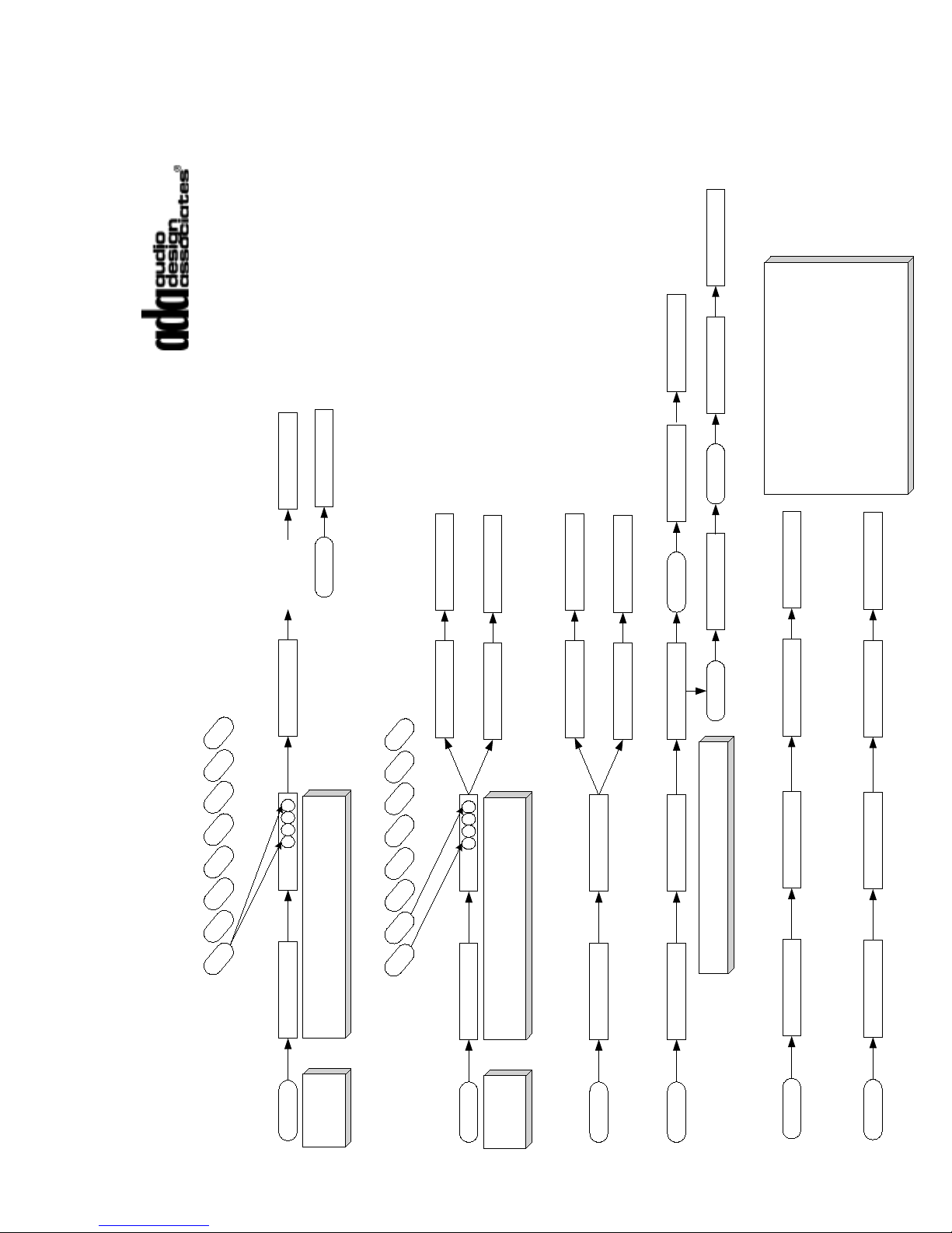
Appendix A - MC-5000 Setup Flow Charts
CODE: _ _ _ _
EXTRA
FM1
FM2
AM
CD1
CD2
DSS
DVD
AUX
Using the 8 source buttons enter the code
"1111 ", where 1 is the source on the far left
(FM1) and eight is on the far right (AUX)
CODE: 1 1 1 1
Press &
Hold EXTRA
CHECK KEYS
Reads Function
EXTRA
Suite-16 System
MC-5000, MC-6000,
MC-3000 OD, MC-3800 OD
Programming Flow Chart
Setup Features
Using the << or >> buttons, you can change
the room number this keypad will control.
Press
Any
Button
CODE: _ _ _ _
EXTRA
FM1
FM2
AM
CD1
CD2
DSS
DVD
AUX
Using the 8 source buttons enter the code
"1112", where 1 is the source on the far left
(FM1) and eight is on the far right (AUX)
CODE: 1 1 1 2
Press &
Hold EXTRA
IR ON
1111 = Check Keys
1112 = IR On/Off
Normal Operation
Normal Operation
IR OFF
Normal Operation
Or
CODE: _ _ _ _
EXTRA
CODE: 1 1 1 3
BLANKING ON
1113 = Blanking On/Off
Normal Operation
BLANKING OFF
Normal Operation
Or
CODE: _ _ _ _
EXTRA
CODE: 1 1 1 6
SET ROOM #
1116 = Set Room Number
<< >>
SET ROOM #
EXTRA
ROOM = #
EXTRA
ROOM = #
Normal Operation
Normal Operation
CODE: _ _ _ _
EXTRA
CODE: 1 1 1 7
1200 BAUD
1117 = Baud Rate 1200
Normal Operation
CODE: _ _ _ _
EXTRA
CODE: 1 1 1 8
19200 BAUD
1118 = Baud Rate 19200
Normal Operation
The keypad's baud rate must match that of
the Suite-16 in order for it to operate.
Typically, the Suite 16 System's baud rate is
set to 19200. However, you may lower the
baud rate to 1200. When doing so, make
certain all keypads, Trinity, Aquarius, and IRL-
5000 are also set to the same baud rate.
On the Suite 16, the baud rate is set
individually on each P-16 Module and V-16
Module using the rotary address switch.
- 87 -
Page 89
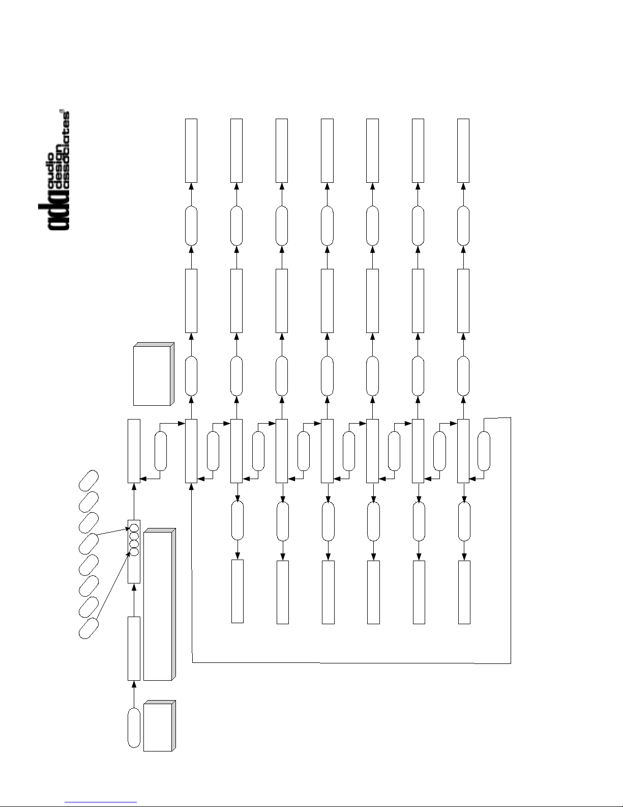
CODE: _ _ _ _
EXTRA
FM1
FM2
AM
CD1
CD2
DSS
DVD
AUX
Using the 8 source buttons enter the code
"1115", where 1 is the source on the far left
(FM1) and eight is on the far right (AUX)
CODE: 1 1 1 5
Press &
Hold EXTRA
CLOCK SET
EXTRA
Suite-16 System
MC-5000, MC-6000,
MC-3000 OD, MC-3800 OD
Programming Flow Chart
Clock Setup
1115 = Clock Set
Normal Operation
Press the >> or
<< button once
to access the
current value.
< >
SET HOURS
< >
SET MINUTES
< >
SET MONTH
< >
SET DATE
< >
SET DAY
< >
SET 12-24
< >
SET YEAR
< >
EXTRA
Normal Operation
EXTRA
Normal Operation
EXTRA
Normal Operation
EXTRA
Normal Operation
EXTRA
Normal Operation
<< >>
MAR 4 18:08
<< >>
MAR 4 [XX]:08
<< >>
MAR 4 18:08
<< >>
MAR 4 18:[XX]
<< >>
MAR 4 18:08
<< >>
[XXX] 4 18:08
<< >>
MAR 4 18:08
<< >>
MAR [XX] 18:08
<< >>
MONDAY
<< >>
[T,W,T,F,S,S,M]
<< >>
24 HOUR MODE
<< >>
[12,24] HOUR MODE
<< >>
YEAR 2002
<< >>
YEAR 20[XX]
- 88 -
Page 90
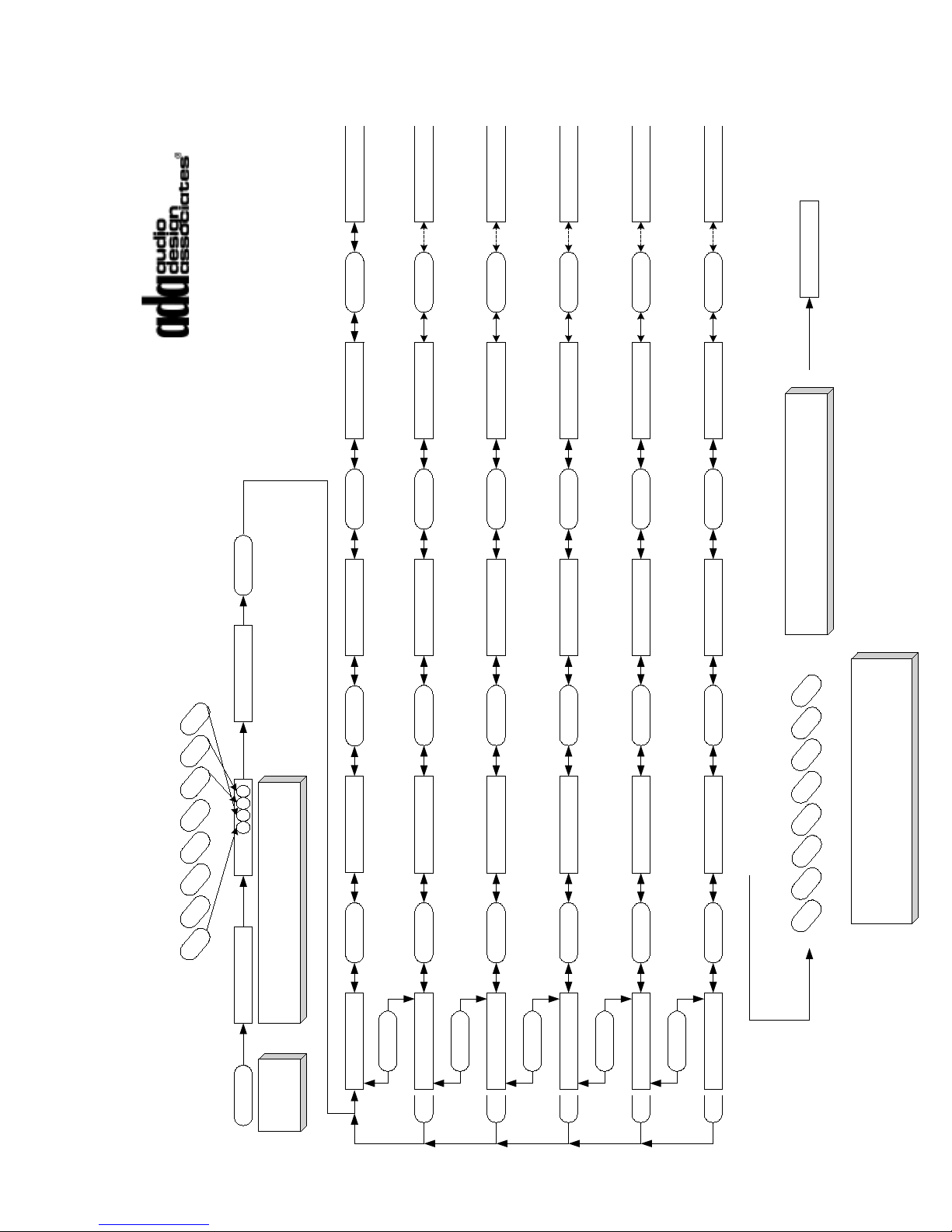
< >
< >
CODE: _ _ _ _
EXTRA
FM1
FM2
AM
CD1
CD2
DSS
DVD
AUX
Using the 8 source buttons enter the code
"1867", where 1 is the source on the far left
(FM1) and eight is on the far right (AUX)
CODE: 1 8 6 7
Press &
Hold EXTRA
INSTALLER
>>
INPUT CONFIG
<< >> SOURCE CNTRL
<< >>
SOURCE LABEL
<< >>
CHECK SETUP
<< >>
PROGRAM ALL
< >
NORMAL INPUT
<< >>
PARTYGROUP 1
< >
<< >>
PARTYGROUP 2
< >
<< >>
PARTYGROUP 3
< >
<< >>
PARTYGROUP 4
< >
INPUT 0
INPUT 1
<< >> INPUT 2
<< >>
INPUT 16
< >
PRTYGRP1-IN 0
PRTYGRP1-IN 1
<< >>
PRTYGRP1-IN 2 << >>
PRTYGRP1-IN16
< >
PRTYGRP2-IN 0
PRTYGRP2-IN 1 << >>
PRTYGRP2-IN 2 << >>
PRTYGRP2-IN16
< >
PRTYGRP3-IN 0
PRTYGRP3-IN 1
<< >>
PRTYGRP3-IN 2
<< >>
PRTYGRP3-IN16
< >
PRTYGRP4-IN 0
PRTYGRP4-IN 1
<< >>
PRTYGRP4-IN 2 << >>
PRTYGRP4-IN16
<< >>
<< >>
<< >>
<< >>
<< >>
FM1
FM2
AM
CD1
CD2
DSS
DVD
AUX
When the desired input is displayed, press the
corresponding source button to lock the input.
INPUT OK
You can set multiple source buttons to the same
input, but only the first instance will illuminate from
feedback.
Suite-16 System
MC-5000, MC-6000,
MC-3000 OD, MC-3800 OD
Programming Flow Chart
Input Configuration
- 89 -
Page 91
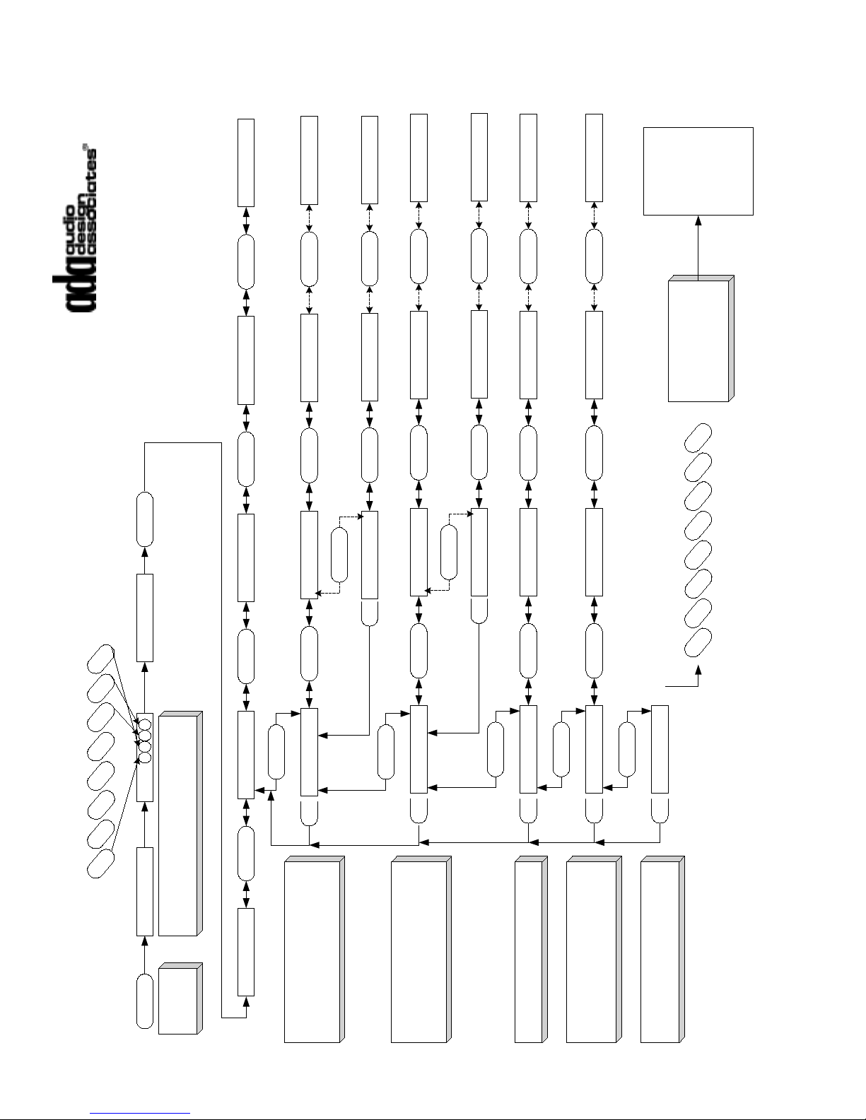
< >
< >
CODE: _ _ _ _
EXTRA
FM1
FM2
AM
CD1
CD2
DSS
DVD
AUX
Using the 8 source buttons enter the code
"1867", where 1 is the source on the far left
(FM1) and eight is on the far right (AUX)
CODE: 1 8 6 7
Press &
Hold EXTRA
INSTALLER
>>
INPUT CONFIG
<< >>
SOURCE CNTRL
<< >>
SOURCE LABEL
<< >>
CHECK SETUP
<< >>
PROGRAM ALL
< >
IR LEARNER
<< >>
< >
SPECIAL CD
< >
<< >>
LVI
< >
<< >>
NO FUNCTION
< > IRL ADDRESS1
IRL 1 OUT 1
<< >>
IRL 1 OUT 8
< >
SPECIAL CD 1
SPECIAL CD 2
<< >>
SPECIAL CD 8
< >
LVI 1
LVI 2
<< >>
LVI 3
<< >>
<< >>
FM1
FM2
AM
CD1
CD2
DSS
DVD
AUX
When the desired source
control option is
displayed, press the
corresponding source
button to lock the control.
IRL OK
TUNER OK
CD OK
LVI OK
NONE OK
While you can use up to nine IRL-
5000’s per system (for 72 IR ports),
typically the most common addressed
used is IRL ADDRESS 1.
Suite-16 System
MC-5000, MC-6000,
MC-3000 OD, MC-3800 OD
Programming Flow Chart
Source Control
< >
IRL ADDRESS9
IRL 9 OUT 1 << >>
IRL 9 OUT 8
< >
<< >>
< >
< >
ADA TUNER
<< >>
< > TUNER ADRS 1
TUNER1-OUT1
<< >>
TUNER1-OUT3
< >
TUNER ADRS 9
TUNER9-OUT1
<< >>
TUNER9-OUT3
< >
<< >>
While you can use up to nine Trinity
Tuner’s per system (for 27 radio
stations), typically the most common
addressed used is TUNER ADRS 1.
You can use up to eight Special CD
Players (Aquarius Outputs)
The LVI is a contact closure device
which provides relay control of
components. You can use up to eight
LVI devices.
The NO FUNCTION option will permit
the keypad source button to select a
device but not control it.
- 90 -
Page 92
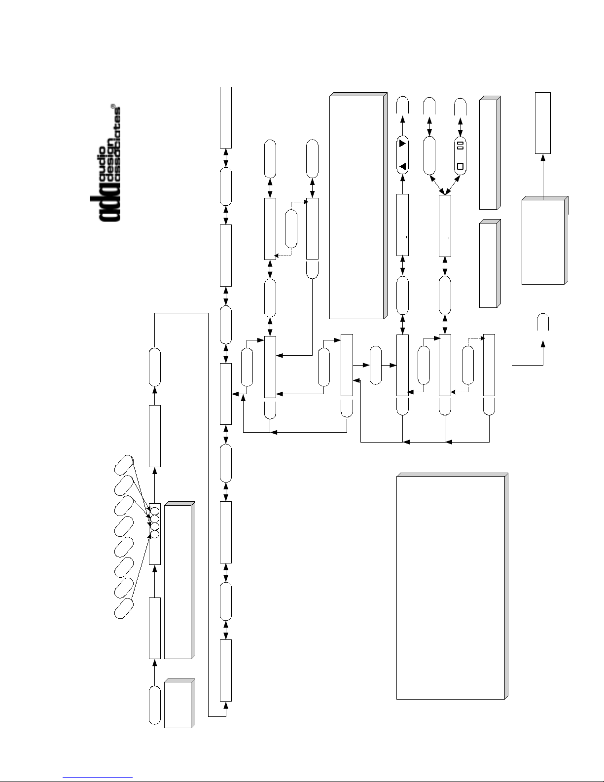
< >
< >
< >
< >
< >
< >
CODE: _ _ _ _
EXTRA
FM1
FM2
AM
CD1
CD2
DSS
DVD
AUX
Using the 8 source buttons enter the code
"1867", where 1 is the source on the far left
(FM1) and eight is on the far right (AUX)
CODE: 1 8 6 7
Press &
Hold EXTRA
INSTALLER
>>
INPUT CONFIG
<< >>
SOURCE CNTRL
<< >>
SOURCE LABEL
<< >>
CHECK SETUP
<< >>
PROGRAM ALL
< >
STNDRD LABEL
<< >>
< >
FORMAT 1
When the desired source
label is displayed, press
the PLAY (>) button to
lock the that label.
LABEL OK
It is important to note, that all sixteen Suite-16 Sources require a label.
These labels are created only once, using either the Suite-16 Keypad
Configuration Program or a single keypad connected to the system.
Ideally, you will want to have all other keypads with a display on line at
the time of the PROGRAM ALL function which loads all keypads from
a single keypad. You can opt to add keypads later and engage the
PROGRAM ALL Function at that time.
Suite-16 System
MC-5000, MC-6000,
MC-3000 OD, MC-3800 OD
Programming Flow Chart
Source Labels
>
FORMAT 8
>
<< >>
< >
< >
CUSTOM LABEL
>
INPUT 1
< >
INPUT 2
< >
<< >>
< >
INPUT 16
<< >>
VOL
I
NPUT 1
There are several way to create a custom label. You can use the built
in labels, modify labels from scratch, or combine both options.
By using the VOL UP or VOL DN buttons, you can access 41 premade
source labels. When the desired label is displayed, press the > button
or use the <<, >>, STOP, & PAUSE buttons to make further changes.
< >
I
NPUT 2
<< >>
Pressing << & >> move
the cursor right and left.
Pressing STOP & PAUSE
advances through characters.
Input 1 Input 2 Input 3 Input 4 Input 5 Input 6 Input 7 Input 8
Format 1
FM TUNER 1FM TUNER 2AM TUNER CD PLAYER 1CD PLAYER 2DSS DVD PLAYERAUXILIARY
Format 2
FM TUNER 1FM TUNER 2AM TUNER CD PLAYER 1CD PLAYER 2CD PLAYER 3DSS DVD PLAYER
Format 3
FM TUNER 1FM TUNER 2AM TUNER CD PLAYER 1CD PLAYER 2DSS 1 DSS 2 AUXILIARY
Format 4
FM TUNER 1FM TUNER 2FM TUNER 3 CD PLAYER 1CD PLAYER 2DSS DVD PLAYERAUXILIARY
Format 5
FM TUNER 1FM TUNER 2FM TUNER 3 CD PLAYER 1CD PLAYER 2CD PLAYER 3DSS DVD PLAYER
Format 6
FM TUNER 1FM TUNER 2FM TUNER 3 CD PLAYER 1CD PLAYER 2DSS 1 DSS 2 AUXILIARY
Format 7
FM TUNER 1FM TUNER 2CD PLAYER 1CD PLAYER 2DSS 1 DSS 2 DVD PLAYERAUXILIARY
Format 8
FM TUNER 1FM TUNER 2CD PLAYER 1CD PLAYER 2DSS 1 DSS 2 AUXILIARY 1 AUXILIARY 2
Input 9 Input 10 Input 11 Input 12 Input 13 Input 14 Input 15 Input 16
All Formats
INPUT 9 INPUT 10 INPUT 11 INPUT 12 INPUT 13 INPUT 14 INPUT 15 INPUT 16
STANDARD SOURCE FORMATS
BY NUMBER
- 91 -
Page 93
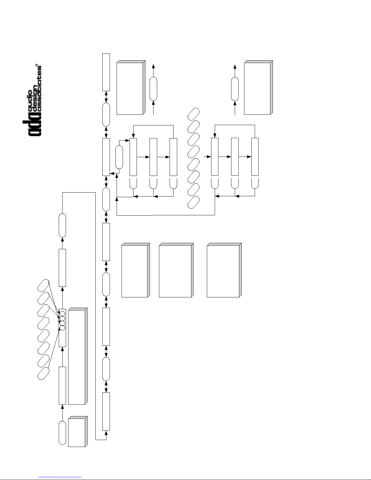
< >
CODE: _ _ _ _
EXTRA
FM1
FM2
AM
CD1
CD2
DSS
DVD
AUX
Using the 8 source buttons enter the code
"1867", where 1 is the source on the far left
(FM1) and eight is on the far right (AUX)
CODE: 1 8 6 7
Press &
Hold EXTRA
INSTALLER
>>
INPUT CONFIG
<< >> SOURCE CNTRL
<< >> SOURCE LABEL
<< >>
CHECK SETUP
<< >>
PROGRAM ALL
< >
INPUT #
Pressing the EXTRA
button will return the
keypad to normal
operation, exiting the
Installer Setup mode.
Suite-16 System
MC-5000, MC-6000,
MC-3000 OD, MC-3800 OD
Programming Flow Chart
Check Setup
< >
INPUT NAME
< >
CONTROL
FM1
FM
2
AM
CD1
CD2
DSS
DVD
AUX
< >
INPUT #
< >
INPUT NAME
< >
CONTROL
EXTRA
EXTRA
Pressing the EXTRA
button will return the
keypad to normal
operation, exiting the
Installer Setup mode.
Check Setup is used to
varify input numbers to
source buttons, input
labels, and secondary
source control options.
Once you enter Check
Setup by pressing the >
button, the display will
cycle through input
number, input name, and
source control.
To verify other sources,
simply press the source
button. The display will
begin to cycle through
that source buttons setup
features.
- 92 -
Page 94
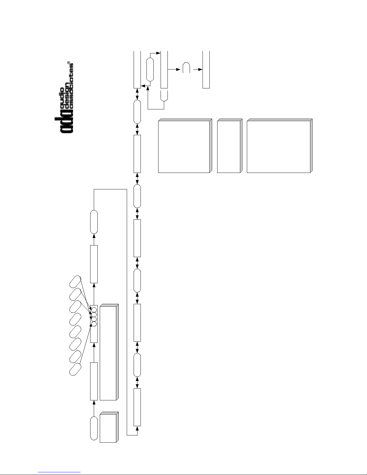
< >
CODE: _ _ _ _
EXTRA
FM2
AM
CD1
CD2
DSS
DVD
AUX
Using the 8 source buttons enter the code
"1867", where 1 is the source on the far left
(FM1) and eight is on the far right (AUX)
CODE: 1 8 6 7
Press &
Hold EXTRA
INSTALLER
>>
INPUT CONFIG
<< >>
SOURCE CNTRL
<< >>
SOURCE LABEL
<< >>
CHECK SETUP
<< >>
PROGRAM ALL
< >
UPLOAD READY
Suite-16 System
MC-5000, MC-6000,
MC-3000 OD, MC-3800 OD
Programming Flow Chart
Program All
The PROGRAM ALL
feature takes the
keypad's information
including input to source
button assignments,
source labels, and
source control options
and uploads them to
other keypads connected
to the network.
Note: If a keypad is not
connected to the
network, it will not get the
upload.
If you have keypads on a
network that are specially
programmed (perhaps
some source buttons are
controlling local only
sources), the PROGRAM
ALL feature from a
keypad without custom
programming will
override the custom
programming previously
created.
< >
UPLOAD DONE
- 93 -
Page 95

Appendix B - System Specifications
AVP-16 Size & Weight (with A-16, P-16, & V-16 Modules)
Width: 19” EIA Rack Mount Height: 5.25” (3 Rack Spaces) Depth: 20”
Weight: 26 lbs
Electrical Specifications
RCA Inputs: 47KΩ Normal Input Volt.: 2V Maximum Input Volt: 2.8V
Balanced Paging Input: 600Ω Normal Input Volt.: 1V
Trigger Voltage Input: 3-24V AC or DC Isolated
Output Voltage:
Source Trigger: 12VDC Max. Source All On: 300mA
Zone Triggers: 12VDC Max. Zone All On: 300mA
Audio Output Impedance: 50Ω Variable & Fixed
Fixed Output Gain: Unity 0dB
AC Power:
Inlet/Outlet: IEC-320
Input Voltage: 120V or 240V, 50-60Hz
Input Power: Max. 250W Fused
Typical Power: (1 x A-16, 1 x P-16, & 1 x V-16 {no Bus power}) = 45W
Max. Bus Power: 6 Amps @ 22VDC Unregulated
Max. Bus Power @ WH-3000/2000: 150mA typical at each port
MC-5011: Typical 45mA (Depending on LED settings)
MC-5000: Typical 60mA (Depending on LED settings)
Switched AC Outlet: IEC-320, 8 Amps Max.
- 94 -
Page 96
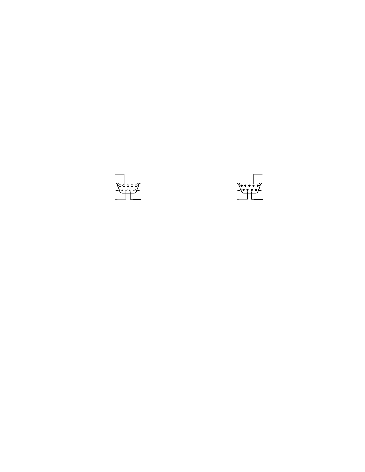
Appendix C - 9 Pin D Connector Information
The following diagram indicates the pin connections for the 9-pin D connectors on
used for zone low voltage triggering.
The P-16 Preamplifier Module, the PTM-1225 and the PTM-1260 all feature female
jacks with the same pin configurations.
The DB-9 Termination Block or 9-Pin Ribbon Cable use male connectors that are
diagrammed below.
Female Connector
(on P-16 & PTM-1260)
Zone 6/Ch 6
Zone 5/Ch 5
Zone 4/Ch 4
Zone 3/Ch 3
Gnd
Zone 1/Ch 1
Zone 2/Ch 2
Male Connector
(on DB-9 or Ribbon Cable)
Pin 4/Zone 6/Ch 6
Pin 1/Gnd
Pin 6/Zone 1/Ch 1
Pin 7/Zone 2/Ch 2
Pin 5/Zone 5/Ch 5
Pin 9/Zone 4/Ch 4
Pin 8/Zone 3/Ch 3
- 95 -
 Loading...