

Page 1
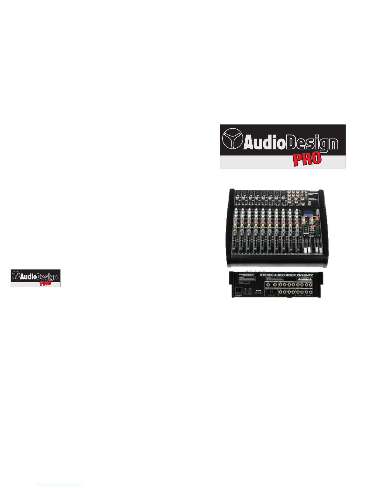
PROFESSIONAL MIXERS
PAMX2.62 - PAMX2.102
OWNER MANUAL
PR OF ES SI ON AL S PE AK ER S, A MP LI FI ER S AN D AC CE SS OR IES
Audiodesign Srl
Via dell’industria, 28 - 42025 CAVRIAGO (RE)
+39 0522 941444 - Fax +39 0522 942363
www.audiodesign-pro.com
info@audiodesign.it
Page 2
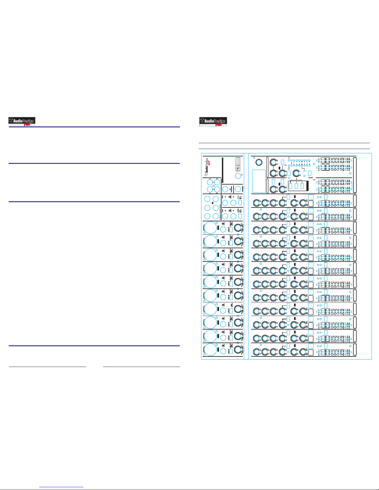
MI XE R PR OF ES SI ON AL I
Serie PAMX2
HIGHHIGH HIGHHIGH HIGHHIGH HIGHHIGH HIGH HIGH HIGH HIGH
EQEQ EQEQ EQEQ EQEQ EQ EQ EQ EQ
MIDMID MIDMID MIDMID MIDMID MID MID MID MID
12 kHz12 kHz 12 kHz12 kHz 12 kHz12 kHz 12 kHz12 kHz 12 kHz 12 kHz 12 kHz 12 kHz
2.5 kHz2.5 kHz 2.5 kHz2.5 kHz 2.5 kHz2.5 kHz 2.5 kHz2.5 kHz 2.5 kHz 2.5 kHz 2.5 kHz 2.5 kHz
LOWLOW LOWLOW LOWLOW LOWLOW LOW LOW LOW LOW
80 Hz80 Hz 80 Hz80 Hz 80 Hz80 Hz 80 Hz80 Hz 80 Hz 80 Hz 80 Hz 80 Hz
PREPREPREPREPREPRE PREPRE PREPRE PREPRE
AUXAUXAUXAUXAUXAUX AUXAUX AUXAUX AUXAUX
FXFXFXFXFXFX FXFX FXFX FXFX
PANPAN PANPAN PANPAN PANPAN PAN PAN BAL BAL
73 51
84
62 9 10 11/12 13/14
MUTEMUTE MUTEMUTE MUTEMUTE MUTEMUTE MUTE MUTE MUTE MUTE
ALT 3-4ALT 3-4 ALT 3-4ALT 3-4 ALT 3-4ALT 3-4 ALT 3-4ALT 3-4 ALT 3-4 ALT 3-4 ALT 3-4 ALT 3-4
CLIPCLIP CLIPCLIP CLIPCLIP CLIPCLIP CLIP CLIP CLIP CLIP
SOLOSOLO SOLOSOLO SOLOSOLO SOLOSOLO SOLO SOLO SOLO SOLO
MUTEMUTE MUTEMUTE MUTEMUTE MUTEMUTE MUTE MUTE MUTE MUTE
dBdB dBdB dBdB dBdB dB dB dB dB
51 62
9 10
13/14
111111 11 11 11 2 2
1 1 1
222222 22 22 22
ALT MAIN MIX
3-4
3
4
L
R
SOLO
SOLO
FX FX
TO AUX
SEND 1
MAIN MIX
ALT 3-4
AUX SENDS STEREO AUX RETURNS
PROGRAM
( PUSH )
2-TR/USB
ALT 3-4
MAIN MIX
SOURCE
MAX
2-TR/USB TO MAIN
PHONES/CTRL R
MAIN SOLO PFL
MODE
SOLO (NORMAL)
PFL (LEVEL SET)
10
5
202
5
20
MIC 7MIC 3 MIC 5MIC 1 MIC 8MIC 4 MIC 6MIC 2 MIC 9 MIC 10
LINE IN 5/6
LINE IN 7/8
RIGHTLEFT/MONO
AUX SENDS
2
1
2
1
FX
INPUT OUTPUT
CD/TAPE
00 SMALL HALL
03 MID HALL
06 BIG HALL
09 CHURCH
10 SMALL ROOM
13 MID ROOM
16 BIG ROOM
19 CHAPEL
20 SPRING
27 SPRING
30 GATED REV
36 REVERSE
40 EARLY REFL
44 AMBIENCE
48 STADIUM
49 AMBIENCE FX
50 DELAY
59 ECHO
60 CHORUS
66 FLANGER
70 PHASER
74 PITCH SHIFT
80 CHORUS & REVERB
82 FLANGER & REVERB
84 PHASER & REVERB
86 PITCH & REVERB
88 DELAY & REVERB
90 DELAY & GATED
91 DELAY & REVERSE
92 DELAY & CHORUS
94 DELAY & FLANGER
96 DELAY & PHASER
98 DELAY & PITCH
24-BIT MULTI-FX PROCESSOR
ULTRALOW-NOISE DESIGN
14-INPUT 2/2-BUS MIC/LINE MIXER
WITH PREMIUM MIC PREAMPLIFIERS AND
DIGITAL 24-BIT MULTI-EFFECTS PROCESSOR
USB AUDIO INTERFACE
73
84 11/12
PAM X 2 .10 2
LAM P
12V
400 mA
USB
INTERFA CE
PAMX2. 102
SET UP MEMO
Introduction
Congratulations on the purchase of a professional mixing console PAMX2.
The mic pre-amplifiers are of high quality level and ensure the best sound quality and a very high
dynamic.
A low noise and distortion-less circuitry assures a natural and transparent reproduction.
USB interface for computer connection.
Precautions:
Caution: When using any electric product , precautions should always be taken, including the
following:
1) Read carefully all instructions before using the product.
2) To reduce the risk, strict supervision is necessary when the product is used near children.
3) Don't use the product near to water sources like sinks, kitchens, wet floors, pools, or similar or
when raining.
4) In case hearing losses or buzzing occur, please contact a doctor.
5) This products should be located so that its position does not interfere or reduce its proper
ventilation.
6) This product should be site away from heat sources such as radiators or any other product
that generate heat.
7) This product should be connected to a power supply line only of the type described on the
operating instructions. Check always the status of the power cable.
8) In case you need to replace the fuse, unplug power supply before replacement. The fuse is
located over the power outlet and needs to be replaced with a fuse of same type and value. If the
fuse blows again, please contact our service. DON'T replace it a second time with a higher value
fuse.
9) Unplug power supply when left unused for a long period of time. Don't draw the cable but pull
out the plug.
10) Make sure that power switch can always be easily reached.
11) Make sure that objects or liquids don't fall inside the product.
12) The product needs to be inspected by authorized or qualified personnel in case:
A- The power cable or plug are damaged
B- Objects or liquids fall inside the product
C- The product has been exposed to rain
D- The product doesn't appear to operate normally or exhibits a marked change in performance.
E- The product has fallen and been damaged.
13) DON'T operate on the product, except indications on the user's manual . Please refer to
authorized and qualified personnel for any other operation.
14) Caution: Don't place objects on the product's power cable or place it in a position where it
could be damaged or cause interferences. Improper installation could cause fire risk and/or personal
injury.
Conformity:
Audiodesign Pro products comply with presently existing directives and standards.
2
Copy this page to fix the set up
Contents
Introduction ..................................... Pag 2
Precautions......................................... Pag 2
Conformity .......................................... Pag 2
Service …….................................. Pag 3
Quick start .......................................... Pag 3
Mono channel ..................................... Pag 4
Stereo channel.................................... Pag 5
Master section .................................... Pag 6
Rear panel .. .............................. Pag 7
Connections........................................ Pag 7
DSP effects ........................................ Pag 7
USB connection.... ............................. Pag 8
Technical specifications....................... Pag 8
Block diagram .. .. ............................... Pag 9
Set Up Memo PAMX2.62.... ................ Pag 10
Set Up Memo PAMX2.102.... .............. Pag 11
Page 3

3
MI XE R PR OF ES SI ON AL I
Serie PAMX2
HIGHHIGH HIGHHIGH HIGH HIGH HIGH HIGH
EQEQ EQEQ EQ EQ EQ EQ
MIDMID MIDMID MID MID MID MID
12 kHz12 kHz 12 kHz12 kHz 12 kHz 12 kHz 12 kHz 12 kHz
2.5 kHz2.5 kHz 2.5 kHz2.5 kHz 2.5 kHz 2.5 kHz 2.5 kHz 2.5 kHz
LOWLOW LOWLOW LOW LOW LOW LOW
80 Hz80 Hz 80 Hz80 Hz 80 Hz 80 Hz 80 Hz 80 Hz
PREPREPREPREPREPRE PREPRE
AUXAUXAUXAUXAUXAUX AUXAUX
FXFXFXFXFXFX FXFX
PANPAN PANPAN PAN PAN BAL BAL
31
4
2 5 6 7/8 9/10
MUTEMUTE MUTEMUTE MUTE MUTE MUTE MUTE
ALT 3-4ALT 3-4 ALT 3-4ALT 3-4 ALT 3-4 ALT 3-4 ALT 3-4 ALT 3-4
CLIPCLIP CLIPCLIP CLIP CLIP CLIP CLIP
SOLOSOLO SOLOSOLO SOLO SOLO SOLO SOLO
MUTEMUTE MUTEMUTE MUTE MUTE MUTE MUTE
dBdB dBdB dB dB dB dB
1 2
5
6
9/10
111111 11 2 2
1 1 1
222222 22
ALT MAIN MIX
3-4
3
4
L
R
SOLO
SOLO
FX FX
TO AUX
SEND 1
MAIN MIX
ALT 3-4
AUX SENDS STEREO AUX RETURNS
PROGRAM
( PUSH )
2-TR/USB
ALT 3-4
MAIN MIX
SOURCE
MAX
2-TR/USB TO MAIN
PHONES/CTRL R
MAIN SOLO PFL
MODE
SOLO (NORMAL)
PFL (LEVEL SET)
10
5
2
0
2
5
20
MIC 3MIC 1 MIC 4MIC 2 MIC 5 MIC 6
LINE IN 5/6
LINE IN 7/8
RIGHTLEFT/MONO
AUX SENDS
2
1
2
1
FX
INPUT OUTPUT
CD/TAPE
00 SMALL HALL
03 MID HALL
06 BIG HALL
09 CHURCH
10 SMALL ROOM
13 MID ROOM
16 BIG ROOM
19 CHAPEL
20 SPRING
27 SPRING
30 GATED REV
36 REVERSE
40 EARLY REFL
44 AMBIENCE
48 STADIUM
49 AMBIENCE FX
50 DELAY
59 ECHO
60 CHORUS
66 FLANGER
70 PHASER
74 PITCH SHIFT
80 CHORUS & REVERB
82 FLANGER & REVERB
84 PHASER & REVERB
86 PITCH & REVERB
88 DELAY & REVERB
90 DELAY & GATED
91 DELAY & REVERSE
92 DELAY & CHORUS
94 DELAY & FLANGER
96 DELAY & PHASER
98 DELAY & PITCH
24-BIT MULTI-FX PROCESSOR
ULTRALOW-NOISE DESIGN
14-INPUT 2/2-BUS MIC/LINE MIXER
WITH PREMIUM MIC PREAMPLIFIERS AND
DIGITAL 24-BIT MULTI-EFFECTS PROCESSOR
USB AUDIO INTERFACE
3
4 7/8
PAM X 2 .6 2
LAM P
12V
400 mA
USB
INTERFA CE
SET UP MEMO
Copy this page to fix the set up
PAMX2. 62
Service
All Audio Design PRO products have been inspected and tested before leaving the factory and , if
properly used, they will work for many years. However, in case of any problem, please proceed in the
following way:
Contact your dealer and inform about the defect you found
In case it won't be possible to solve the problem with the dealer, the product needs to be returned,
preferably in its original packaging or in a proper packing to protect it during the transport. Purchase
documents must be produced too.
Your dealer will arrange the shipment to our service centre.
QUICK START:
Start up:
1. Turn the power switch OFF.
2. Set "down" all TRIM controls (all counter clockwise ) and FADER ( all down) .
3. Center EQ controls (High - Mid - Low) and PAN controls (12 hours).
4. Set all push buttons in their "off" position (button up).
5. Set "down" all master section controls (counter clockwise and down)
Connections:
If you already know how you want to connect the mixer, go ahead and connect. If you prefer to inspect
operation, please follow these instructions:
1. Plug a microphone or a mono signal source into one of the mono channels.
2. or a stereo signal source into one the stereo channels.
3. Connect MAIN OUTPUTS to an amplifier (XLR Balanced / Jack Balanced).
4. Turn power switch on. The blue led (POWER) lights up.
Set the levels:
1. Push the button "MODE" to use LED level indicators , in PFL mode (Level Set)
2. Push the button "SOLO " of the channel you intend to set up.
3. Set the TRIM potentiometer of the channel until the LED indicators (left column) are next to "0" level or
in any case never over +5 level. Avoid absolutely to reach level + 10/Clip.
4. Release button "SOLO" of the channel you have just set up.
5. Repeat procedure from point 2 to point 4 for each channel you intend to connect
Mixing:
1. Set the FADER of each channel at "0" position
2. Release the button "MODE" to set it in position "SOLO" (NORMAL)
3. Turn the button "MAIN MIX" to see outlet signal level on the LED indicators.
4. Turn up "MAIN MIX" to desired level, in relation to the amplifiers / speakers you are using. Preferably,
don't exceed level "0" or "+5" on the LED indicators.
5. Adjust FADER of each channel to obtain your own mix.
6. If necessary, adjust tones and repeat above " set levels" procedures
General indications:
1. The optimum FADER position is near to 0 while the optimum position for the MAIN MIX is the one that
don't exceed level 0 / +5 on the LED level indicators.
2. Check that the level of each power input is the same that you set up during the "set the levels"
operations, even if you have eventually operated on EQ of each channel. If necessary, each channel can be
adjusted even during the performance through TRIM set up and monitored throught the LED indicators. Avoid
absolutely that CLIP indicator of each channel lights up.
3. In case you intend to connect further sources, please take care to turn down "MAIN MIX" slider
Page 4

4
MI XE R PR OF ES SI ON AL I
Serie PAMX2
Left Right
10
10
0
15
20
30
40
60
Mic 1
Bal
or
Unbal
LINE IN
Low Cut
75 Hz
18 dB/Oct
+10
- 40
+10
+60
TRIM dB/dBu
EQ
HIGH
12 KHz
MID
2.5 KHz
LOW
80 Hz
AUX
PRE
Mic 1
FX
PAN
MUTE
CLIP
SOLO
0
+15
- 15
0
+15
- 15
0
+15
- 15
- ¥
0
+ 15
0
- ¥
+ 15
1
MUTE
ALT 3-4
Fig 1
MONO CHANNELS
MI XE R PR OF ES SI ON AL I
Serie PAMX2
9
SCHEMA A BLOCCHI
1. MIC: XLR balanced microphone input for dynamic and capacitor
microphones. By means of the XLR connector, it's possible to feed
condenser microphones. Operate button "PHANTOM ON" to activate this
function ( located on the rear panel) This function is monitored through the
red LED switch on + 48 V located over the LED level indicators. Use of
dynamic microphones with phantom power supply is generally not
recommended. *
2. LINE: balanced or unbalanced line level input , 6,3 mm. Jack
connector.
Important: DON'T use MIC and LINE input signal at the same time
!!!! *
3. This switch activates high-pass filter at 75 Hz - 18dB/Oct
4. TRIM: To adjust channel input level.
Should always be completely turned counter clockwise during connection
of any source
5. EQ HIGH: This control adjusts +/- 15 dB with a "shelving" curve
shape
at 12 kHz.
6. EQ MID: This control adjusts +/- 15 dB with a band center at
2.5 kHz.
7. EQ LOW: This control adjusts +/- 15 dB with a "shelving" curve
shape at 80 Hz.
8. AUX: This control adjusts the output signal level
AUX SENDS 1, controlled through general adjustment (18). This signal is
normally "post" FADER but could become "pre" FADER by operating the
button (9)
9. This button operates the pre/post FADER level of the AUX control
10. FX: This control adjusts signal level to send to AUX SENDS 2 and
to DSP, controlled through general adjustment (19). This signal is always
"post" FADER
11. PAN: It adjusts the stereo scene by adjusting the signal levels to
send to right and left outputs.
12. MUTE: This dual-purpose switch turns off the channel and sends at
the same time a signal to an alternative mixing (ALT 3/4 ). Function is on
when yellow LED lights up.
13. CLIP: The red LED is dual-purpose too: it indicates "SOLO"
function (See point 14) or indicates CLIPPING mode.
Important: in case LED lights up indicating clipping mode, operate by
reducing the TRIM
14. SOLO: This button sends the signal to PHONES and CONTROL
ROOM OUT outlets and allows you to hear signals through your
headphones and view signal on LED level indicators. Operating the
"MODE" switch of the main section, it's possible to choose pre or post
FADER signal.
15. FADER: It adjusts the level of the channel signal.
* See connection scheme on page 7
Page 5

5
MI XE R PR OF ES SI ON AL I
Serie PAMX2
Left Right
10
10
0
15
20
30
40
60
Bal
or
Unbal
EQ
HIGH
12 KHz
MID
2.5 KHz
LOW
80 Hz
AUX
PRE
FX
PAN
MUTE
CLIP
SOLO
0
+15
- 15
0
+15
- 15
0
+15
- 15
- ¥
0
+ 15
0
- ¥
+ 15
9/10
MUTE
ALT 3-4
MONO
L
R
LEVEL
LINE IN 9/10
+ 4
-10
Fig 2
16
17
STEREO CANNELS
MI XE R PR OF ES SI ON AL I
Serie PAMX2
PORTA USB
16. L channel of a stereo source or a mono signal can be connected
to this 6,3 mm Jack input. Signal can be either balanced or
unbalanced*
17. Only R channel of a stereo signal can be connected to this 6.3
mm input
3. This switch sets the channel input level (+ 4 / - 10 dB
attenuation)
5. EQ HIGH: This control adjusts +/- 15 dB with a "shelving" curve
shape
at 12 kHz.
6. EQ MID: This control adjusts +/- 15 dB with a band center at
2.5 kHz.
7. EQ LOW: This control adjusts +/- 15 dB with a "shelving" curve
shape at 80 Hz.
8. AUX:This control adjusts the output signal level
AUX SENDS 1, controlled through general adjustment (18). This
signal is normally "post" FADER but could become "pre" FADER by
operating the button (9)
9. This button operates the pre/post FADER level of the AUX
control
10. FX: This control adjusts signal level to send to AUX SENDS 2
and to DSP, controlled through general adjustment (19).This signal is
always "post" FADER
11. PAN: It adjusts the stereo scene by adjusting the signal levels to
send to right and left outputs.
12. MUTE: This dual-purpose switch turns off the channel and
sends at the same time a signal to an alternative mixing (ALT 3/4 ).
Function is on when yellow LED lights up.
13. CLIP: The red LED is dual-purpose too: it indicates "SOLO"
function (See point 14) or indicates CLIPPING mode.
Important: in case LED lights up indicating clipping mode, operate by
reducing the TRIM
14. SOLO: This button sends the signal to PHONES and CONTROL
ROOM OUT outlets and allows you to hear signals through your
headphones and view signal on LED level indicators. Operating the
"MODE" switch of the main section, it's possible to choose pre or post
FADER signal.
15. FADER: It adjusts the level of the channel signal.
* See connection scheme on page 7
Audiodesign PRO professional
mixers PAMX2 series, are supplied
with a full speed USB port which you
can connect to a computer and allows
you to exchange CD-quality audio
between mixer and computer; mixer
operates also as and external
soundcard.
Recording on PC can be made using
the computer's built-in audio recorder,
or better, using a dedicated software.
To ensure that the mixer is correctly
recognized by the PC, always turn on
the mixer before inserting USB cable
into the PC.
When turning off, turn off the
computer first until shut down
process is completed and then turn
off the mixer.
Windows automatically recognizes
the mixer at the first connection and
proceed to install necessary drivers,
eventually will require to insert the
Windows CD.
Open the control panel and select
"USB Audio Codec" as default sound
recording and playback device. Also
for Macintosh, the selection of "USB
Audio Codec" is the only action
required.
Better performances can be obtained
using specific Digital Audio
Workstation software, in which case
the specific installation instruction
must be followed.
To use the mixer for playback from
PC, operate buttons and controls 2
TR/USB, for MAIN MIX or
PHONES/CTRL R outputs.
For recording to PC from Mixer while
it's working, start registration on PC's
software and adjust its level from the
MAIN MIX Fader.
SPECIFICATIONS
Section L evel and datas
MONO INPUT CHANNELS
Mic In
Sensitivity from 0 to - 60 dB
XLR-F Balanced
Impedance 2 Kohm
Line In
Jack Balanced
Impedance 10-20 Kohm (Bal-Unb al)
EQ
STEREO INPUT CHANNELS
Line In
Sensitivity from - 10 a + 4 dB
Impedance 20 Kohm
EQ
HIGH ±15 dB @ 12 KHz shelving
MID ±15 dB @ 2.5 KHz peaking
LOW ±15 dB @ 80 Hz shelving
MASTER SECTION
Nominal Output level + 4 dBu
2-TRK - CD/TAPE
Nominal Output level 0 dBu
Nominal Output level - 10 dBv
HEADPHONES
Min Impedance 32 ohm
Jack Stereo
Max Output (2x) 193 mW
DIGITAL EFFECT PROCESSOR
Preset
Delay STEREO, MONO e TAP
Modulations CHORUS e F LANGER
Combinations REV + STE REO DELAY, REV + MONO DELAY,
REV +CHORUS e REV + FL ANGER
USB INTERFACE
Version
Resolution
Sampling
Rate
MAIN SPECIFICATIONS
Max Level
Crosstalk
Hum and Noise
THD + Noise
Weight
Dimensions (WxDxH)
Connector
XLR / Jack Bal.
Jack Unbal mono
RCA
Fully compliant with USB 1.1
16-Bit Delta Sigma ADC e DAC
DAC: 32, 44.1, 48 kHz
ADC: 8, 11.025, 16, 22.05, 32, 44.1 , 48 kHz
all outputs +22 dBu
meas at 1 KHz > 82 dB
unweighted < -93 dBu
a +4dB, 1kHz < 0,008 %
Reverbs: HALL, ROOM, VOCAL e PLATE
MAIN MIX OUT
C. ROOM output
AUX SENDS 1
AUX SENDS 2
Jack Unbal mono
Jack Unbal mono
Jack Unbalanced
Jack Balanced
Jack Unbalanced
PAMX 2.62 PAMX 2.102
5.3 Kg4.0 Kg
34.4 x 35 x 11.2 cm 45 x 35 x 11.2 cm
Nominal Output level + 4 dBu
Nominal Output level + 4 dBu
Nominal Output level + 4 dBu
HIGH ±15 dB @ 12 KHz shelving
MID ±15 dB @ 2.5 KHz peaking
LOW ±15 dB @ 80 Hz shelving
Sensitivity from - 10 a + 4 dB
8
Page 6

MI XE R PR OF ES SI ON AL I
Serie PAMX2
MI XE R PR OF ES SI ON AL I
Serie PAMX2
LEFT
RIGHT
CONNECTIONS
XLR 3 Female
XLR 3 Male
Jack 6,3 Balanced Jack 6,3 Unbalanced
Jack 6,3 Stereo
I
I
0 0
MAIN OUTPUT
CHANNEL INSERT
MAIN OUTPUT
POWER
ON
PHANTOM
ON
PIN 2 = HOT - PIN 3 = COLD
ALT 3-4 OUTPUT
CONTROL ROOM OUT
4 3 R L
6 5 4 3 2 1
R L
R L
16491648
1642
1644
46
471643 45
MAIN INSERT
R L
1650
1651
USB
INTERFACE
6 7
MASTER SECTION
00 SMALL HALL
03 MID HALL
06 BIG HALL
09 CHURCH
10 SMALL ROOM
13 MID ROOM
16 BIG ROOM
19 CHAPEL
20 SPRING
27 SPRING
30 GATER REV
36 REVERSE
40 EARLY REFL
44 AMBIENCE
48 STADIUM
49 AMBIENCE FX
50 DELAY
59 ECHO
60 CHORUS
66 FLANGER
70 PHASER
74 PITCH SHIFT
80 CHORSU & REVERB
82 FLANGER & REVERB
84 PHASER & REVERB
86 PITCH & REVERB
88 DELAY & REVERB
90 DELAY & GATED
91 DELAY & REVERSE
92 DELAY & CHORUS
94 DELAY & FLANGER
96 DELAY & PHASER
98 DELAY & PITCH
DSP EFFECTS
REAR PANEL
41
10
10
0
15
20
30
40
60
10
10
0
15
20
30
40
60
10
10
0
15
20
30
40
60
10
10
0
15
20
30
40
60
SOLO
- ¥
0
+ 15
- ¥
0
+ 15
-PROGRAM
(PUSH)
- ¥
0
+ 15
TO AUX
SEND 1
- ¥
0
+ 15
ALT 3-4 MAIN MIX
3
4
L
R
MODE
SOLO (NORMAL)
PFL (LVEL SET)
MAIN SOLO PFL
ALT 3-4
MAIN MIX
SOURCE
0
- ¥
+ 15
0
- ¥
+ 15
AUX SENDS
STEREO AUX RETURNS
FX
SOLO
PHONES/CTRL R
FX
MAIN MIX
ALT 3-4
LEFT / MONO RIGHT
STEREO AUX RETURNS AUX SEND
1 1
2 2
FX
INPUT OUTPUT
CD/TAPE
R
L
R
L
FX FOOTSW
PHONES LAMP 12 V CC - 400 mQ
18
19
20
21
22
23
24
25
26
27
28
29
30 31
32
33
34
35
36
37
38
39
40
2TR/USB
2TR/USB TO MAIN
+48V
P0WER
CLIP
10
5
2
0
2
5
20
+ 48 V -
Phantom Power Supply
LEVEL
-20
-15
-10
-8
-3
CLIP
24-BIT DUAL ENGINE DSP
24-BIT A/D & D/A CONVERTER
INSERT CONNECTIONS
OUT
IN
MIXER
INSERT
IN
Compressor
Processor
Equalizer
OUT
Compressor
Processor
Equalizer
AUX SENDS
18. It controls the signal general level to
send to AUX SENDS 1. Push button SOLO to
view level on LED indicators.
19. It controls the signal general level to
send to AUX SENDS 2 and to DSP; Level is
shown on DPS LED indicators. Push button
SOLO to view level on LED indicators too.
20. This unbalanced Jack sends the signal
of all input channels AUX (8) controls together
with STEREO AUX RETURNS 1 (25) signal.
21. This unbalanced Jack sends the signal
of all input channels FX (10) controls
STEREO AUX RETURNS
22. It controls the signal level arriving from
STEREO AUX RETURNS 1 (25) towards the MAIN MIX
23. It controls the signal level arriving from STEREO AUX
RETURNS 1 (25) towards AUX SEND 1 (20).
24. It controls the signal level sent to STEREO AUX
RETURNS 2 (26)
It also determine the action level of the internal DSP. The button
located next to it allows you to send the signal to MAIN MIR or to
ALT 3-4.
25. Unbalanced Jack connectors of the auxiliary stereo input.
In case of mono signal, use left connector
26. Unbalanced Jack connector of the auxiliary stereo input.
In case of mono signal, use left connector
HEADPHONES
27. Switch to select the source to send to the headphones
output and to view signal level on the LED indicators
28. Controls general signal level to send to headphones Jack
and CONTROL ROOM OUT output
29. Jack stereo to connect headphones
CD/TAPE - 2TR/USB
30. Auxiliary input RCA connectors
31. Auxiliary output RCA connectors (MAIN MIX)
32. Button to send input signal to CD/TAPE and/or
2TR/USB to MAIN MIX, and vice versa to send output
signal from MAIN MIX to CD/TAPE and/or 2TR/USB.
DSP
33. DSP - Digital effect processor. Rotate this switch in both
directions to preset effect you want to use. See details of effects
on page 7-
Various
34. LED BLUE light Mixer is on
35. LED RED light, Phantom is connected
36. LED level indicators (red Clipping)
37. MODE: Button to select the signal (SOLO or PFL) to
send to LED level indicator.
38. FX FOOTSW: allows you to use a footswitch to use or
not to use preset effects
39. LAMP: bayonet connector to plug a lamp (12 v CC - 400
mA max) to MAIN - ALT FADER
MAIN - ALT FADER
40. FADER to control left and right levels of the ALT 3-4 bus
41. FADER to control left and right level of the main MAIN
MIX bus
42. Power supply and fuse connection
43. Mixer switch on button
44. Phantom + 48V power supply switch
45. USB connection
46. 6.3 mm Jack balanced connections for main output MAIN OUTPUTni
47. XLR balanced connections for main output MAIN OUTPUT
48. 6.3 mm Jack unbalanced connections for ALT 3-4 output
49. Control Room output or additional output of MAIN MIX program with 6.3 mm mono
unbalanced Jack
50. Stereo Jack connections of each channel, to operate signal externally (equalization /
compression/etc.)
51. MAIN MIX output stereo Jack connections to operation signal externally
 Loading...