

Page 1

PAMX1.24
Audiodesign Srl
Via dell’industria, 28 - 42025 CAVRIAGO (RE)
+39 0522 941444 - Fax +39 0522 942363
www.audiodesign-pro.com
info@audiodesign.it
Picture
PR OF ES SI ON AL S PE AK ER S, A MP LI FI ER S AN D ACCESSORIES
PROFESSIONAL MIXER
OWNER MANUAL
Page 2
2
Serie PAMX1
PAMX1.24
SET UP MEMO
10
PAM X 1. 2 4
INSERT 1
INSERT 2
11
Introduction
Congratulations on the purchase of a professional mixing console PAMX1.
The mic pre-amplifiers are of high quality level and ensure the best sound quality and a very high
dynamic.
A low noise and distortion-less circuitry assures a natural and transparent reproduction.
Precautions:
Caution: When using any electric product , precautions should always be taken, including the
following:
1) Read carefully all instructions before using the product.
2) To reduce the risk, strict supervision is necessary when the product is used near children.
3) Don't use the product near to water sources like sinks, kitchens, wet floors, pools, or similar or
when raining.
4) In case hearing losses or buzzing occur, please contact a doctor.
5) This products should be located so that its position does not interfere or reduce its proper
ventilation.
6) This product should be site away from heat sources such as radiators or any other product
that generate heat.
7) This product should be connected to a power supply line only of the type described on the
operating instructions. Check always the status of the power cable.
8) In case you need to replace the fuse, unplug power supply before replacement. The fuse is
located over the power INtlet and needs to be replaced with a fuse of same type and value. If the fuse
blows again, please contact our service. DON'T replace it a second time with a higher value fuse.
9) Unplug power supply when left unused for a long period of time. Don't draw the cable but pull
out the plug.
10) Make sure that power switch can always be easily reached.
11) Make sure that objects or liquids don't fall inside the product.
12) The product needs to be inspected by authorized or qualified personnel in case:
A- The power cable or plug are damaged
B- Objects or liquids fall inside the product
C- The product has been exposed to rain
D- The product doesn't appear to operate normally or exhibits a marked change in performance.
E- The product has fallen and been damaged.
13) DON'T operate on the product, except indications on the user's manual . Please refer to
authorized and qualified personnel for any other operation.
14) Caution: Don't place objects on the product's power cable or place it in a position where it
could be damaged or cause interferences. Improper installation could cause fire risk and/or personal
injury.
Master section .................................... Pag 6
Rear panel .. .............................. Pag 7
Connections........................................ Pag 7
Technical specifications....................... Pag 8
Block diagram .. .. ............................... Pag 9
Set Up Memo ..................... ................ Pag 10
Set Up Memo ....................... .............. Pag 11
Contents
Introduction ..................................... Pag 2
Precautions......................................... Pag 2
Conformity .......................................... Pag 2
Service …….................................. Pag 3
Quick start .......................................... Pag 3
Mono channel ..................................... Pag 4
Stereo channel.................................... Pag 5
PR OF ES SI ON AL M IX ER S
PR EE SS IO NA L MI XE RS
Photocopy this page to remind set up
Page 3

3
Serie PAMX1
SET UP MEMO
Photocopy this page to remind set up
PAMX1. 24
10
PAM X 1. 2 4
INSERT 1
INSERT 2
10
Service
All Audio Design PRO products have been inspected and tested before leaving the factory and , if
properly used, they will work for many years. However, in case of any problem, please proceed in the
following way:
Contact your dealer and inform about the defect you found
In case it won't be possible to solve the problem with the dealer, the product needs to be returned,
preferably in its original packaging or in a proper packing to protect it during the transport. Purchase
documents must be produced too.
Your dealer will arrange the shipment to our service centre.
QUICK START:
Start up:
1. Turn the power switch OFF.
2. Set "down" all GAIN AND LEVEL controls (all counter clockwise )
3. Center EQ controls (High - Mid - Low) and PAN controls (12 hours).
4. Set all push buttons in their "off" position (button up).
5. Set "down" all master section controls (counter clockwise and down)
Connections:
If you already know how you want to connect the mixer, go ahead and connect. If you prefer to check
operation, please follow these instructions:
1. Plug a microphone or a mono signal source into one of the mono channels.
2. Or a stereo signal source into one of the stereo channels.
3. Connect MAIN OUTPUTS to an amplifier (Jack Balanced).
4. Turn power switch on. The blue led (POWER) lights up.
Mixing:
1. Set the LEVEL of each channel at "0" position
2. Turn up "MAIN MIX" to desired level, in relation to the amplifiers / speakers you are using. Preferably,
don't exceed level "0" or "+6" on the LED indicators.
3. Adjust LEVEL of each channel to obtain your own mix.
6. If necessary, adjust tones and repeat above " set levels" procedures
General indications:
1. The optimum GAIN and/or LEVEL position is near to 0 while the optimum position for the MAIN MIX is
the one that don't exceed level 0 / +6 on the LED level indicators.
2. In case you intend to connect further sources, please take care to turn down "MAIN MIX" slider
Conformity:
Audiodesign Pro products comply with presently existing directives and standards.
PR OF ES SI ON AL M IX ER S
PR EE SS IO NA L MI XE RS
Page 4

4
MONO CHANNELS
9
BLOCK DIAGRAM
Left Right
Bal
or
Unbal
Low Cut
MIC: 10 60 dB
EQ
HI
12 KHz
MID
2.5 KHz
LOW
80 Hz
LEVEL
INSERT 1
FX
PAN
PEAK
0
+15
- 15
0
+15
- 15
0
+15
- 15
- ¥
0
+ 15
0
- ¥
+ 15
Fig 1
GAIN
LINE:+10 -40 dBu
Serie PAMX1 Serie PAMX1
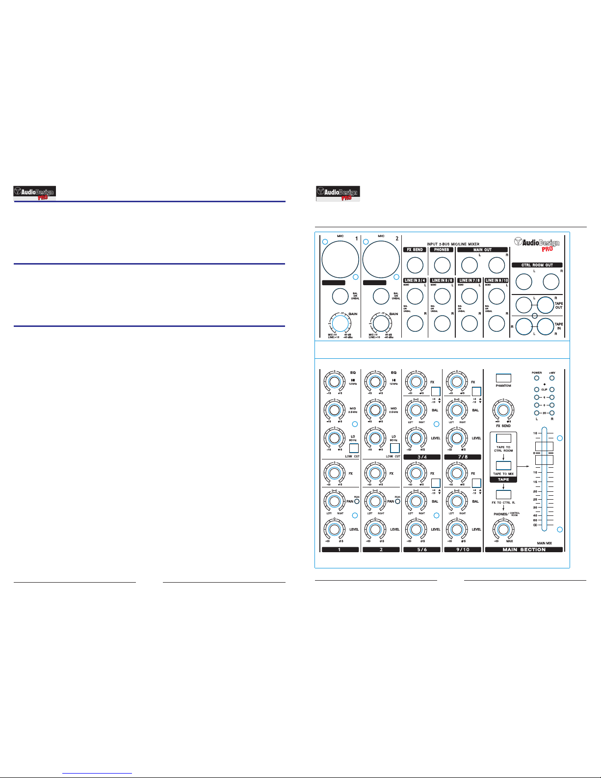
1. MIC: XLR balanced microphone input for dynamic and condenser
microphones. By means of the XLR connector, it's possible to feed
condenser microphones. Operate button "PHANTOM ON" to activate this
function (located on the master sectionl) This function is monitored
through the red LED switch on + 48 V located over the LED level
indicators. Use of dynamic microphones with phantom power supply is
generally not recommended. *
2. LINE: balanced or unbalanced line level input, 6,3 mm. Jack
connector. Important: DON'T use MIC and LINE input signal at the same
time !!!! *
3.
4.
5.
6.
7.
8.
9.
10.
11.
* See connection scheme on page 7
GAIN: To adjust channel input level. Should always be completely
turned counter clockwise during connection of any source
EQ HIGH: This control adjusts +/- 15 dB with a "shelving" curve
shape at 12 kHz.
EQ MID: This control adjusts +/- 15 dB with a band center at
2.5 kHz.
EQ LOW: This control adjusts +/- 15 dB with
Hz.
This switch activates high-pass filter at 75 Hz - 18dB/Oct
FX: This control adjusts signal level to send to FX SENDS,
controlled through general adjustment (19). This signal is always "post"
FADER
PAN: It adjusts the stereo scene by adjusting the signal levels to
send to right and left outputs.
LEVEL: It adjusts the level of the channel signal.
PEAK: The red LED indicates CLIPPING mode.
Important: in case LED lights up indicating clipping mode, operate by
reducing the TRIM
a "shelving" curve
shape at 80
PR OF ES SI ON AL M IX ER S
PR EE SS IO NA L MI XE RS
Page 5

5
PR OF ES SI ON AL M IX ER S
STEREO CHANNELS
PR EE SS IO NA L MI XE RS
8
SEPCIFICATIONS
Left Right
LEVEL
FX
BAL
- ¥
0
+ 15
0
- ¥
+ 15
Fig 2
Bal
or
Unbal
MONO
R
L
LINE IN 3/4
+4
-10
16
17
Serie PAMX1 Serie PAMX1
12. L channel of a stereo source or a mono signal can be
connected to this 6,3 mm Jack input. Signal can be either
balanced or unbalanced*
13. Only R channel of a stereo signal can be connected to this
6.3 mm input
14. This switch sets the channel input level (+ 4 / - 10 dB
attenuation)
15. FX: This control adjusts signal level to send to FX
SENDS, controlled through general adjustment (19).This signal is
always "post" FADER
16. BAL: It adjusts the stereo scene by adjusting the signal
levels to send to right and left outputs.
17. LEVEL: It adjusts the level of the channel signal.
* See connection scheme on page 7
Section Level and datas
MONO INPUT CHANNELS
Mic In
Sensitivity from 0 to - 60 dB
XLR-F Balanced
Impedance 2 Kohm
Line In
Jack Balanced
Impedance 10-20 Kohm (Bal-Unbal)
EQ
STEREO INPUT CHANNELS
Line In
Sensitivity from - 10 a + 4 dB
Impedance 20 Kohm
MASTER SECTION
TAPE OUT
Nominal Output level 0 dBu
Nominal Output level - 10 dBv
HEADPHONES
Min Impedance 32 ohm
Jack Stereo
Max Output (2x) 193 mW
MAIN SPECIFICATIONS
Max Level
Crosstalk
Hum and Noise
THD + Noise
Weight
Dimensions (WxDxH)
Connector
XLR / Jack Bal.
Jack Unbal mono
RCA
all outputs +22 dBu
meas at 1 KHz > 82 dB
unweighted < -93 dBu
a +4dB, 1kHz < 0,008 %
MAIN OUT
C. ROOM out
FX SENDS1
Jack Unbal mono
Jack Unbalanced
Jack Balanced
Jack Unbalanced
PAMX 1.24
.0 Kg
cm
Nominal Output level + 4 dBu
Nominal Output level + 4 dBu
Nominal Output level + 4 dBu
HIGH ±15 dB @ 12 KHz shelving
MID ±15 dB @ 2.5 KHz peaking
LOW ±15 dB @ 80 Hz shelving
Sensitivity from - 10 a + 4 dB
Page 6

LEFT
RIGHT
CONNECTIONS
XLR 3 Female
XLR 3 Male
Jack 6,3 Balanced Jack 6,3 UnBalanced
Jack 6,3 Stereo
6 7
MASTER SECTION
REAR PANNEL
+ 48 V -
Phantom Power Supply
LINE IN 3/4 LINE IN 5/6 LINE IN 7/8 LINE IN 9/10
FX SEND PHONES MAIN OUT
TAPE
OUT
Bal
or
Unbal
MONO
R
L
Bal
or
Unbal
MONO
R
L
Bal
or
Unbal
MONO
R
L
Bal
or
Unbal
MONO
R
L
L
R
CTRL ROOM OUT
TAPE
IN
L
R
L
R
L
R
PAMX 1. 2 4
283229 30
31
32
34
Fig 3
18
19
22
23
24
21
0
- ¥
+ 15
- ¥
0
MAX
27
20
25
26
Fig 4
18.
19. FX SENDS: It control the general level of the
signal sent do FX SENDS output .
20. TAPE TO CTRL ROOM: Sends the
signal to Jack 6.3 CTRL ROOM OUT output
21. TAPE TO MIX:
MAIN MIX
22. FX TO CTRL ROOM: Sends the FX signal to
Jack 6.3 CTRL ROOM OUT output
23. PHONES/CTRL ROOM: Control the level of
the phone output (PHONES) and of the signal to send
to CTRL ROOM OUT output
24. POWER: BLU show that power is on
25. + 48 V: RED LED show that Phantom is on
26. LED METER: (RED LED Clipping)
27. MAIN MIX: FADER to set the left and rigth
signal of main bus MAIN MIX.
Phantom + 48V power supply switch
RCA TAPE
IN
Sends the RCA TAPE IN signal
to
(31)
(31)
LED
28. Stereo Jack Connector for FX
bus, for external signal operation
(equalizer / compression, ecc)
29.
30. Balanced jack 6,3 output
connections MAIN OUT
31.
CTRL ROOM OUT
32. RCA connectors for auxiliary
output (MAIN MIX)
33. RCA connectors for auxiliary
input
34. Balanced jack 6,3 for stereo
input (Channles 3/4 - 5/6 - 7/8 e 9/10)
Jack stereo to connect headphones
Balanced jack 6,3 output
connections
CONNECTIONS SECTION
PAMX1. 2 4
POWER
ON
35
35. Power supply and fuse connection
Serie PAMX1 Serie PAMX1
PR OF ES SI ON AL M IX ER S
PR EE SS IO NA L MI XE RS
 Loading...