

Page 1
Issue No. 20
211 amperes peak current for $1100!
(See the power amplifier reviews.)
Retail price: $7.50
In this issue:
We launch our power amplifier survey with seven
reviews for openers, circuit critiques, a new method
of measuring dynamic performance into complex
loads, and an amplifier tutorial by Dr. Rich.
The latest-and-greatest DCM "TimeWindow" is
reviewed, along with other interesting loudspeakers.
We report our initial tests of the DCC system.
Part III of the Ranada interviews with the elite of
audio brings you yet another original thinker.
Plus other test reports, editorials, our
famous "Hip Boots" column, letters
to the Editor, and lots of CD reviews.
pdf 1
Page 2

Issue No. 20 Late Summer 1993
Editor and Publisher Peter Aczel
Contributing Technical Editor David Rich
Contributing Editor at Large David Ranada
Technical Consultant Steven Norsworthy
Columnist Tom Nousaine
Cartoonist and Illustrator Tom Aczel
Business Manager Bodil Aczel
The Audio Critic® (ISSN 0146-4701) is published quarterly for $24
per year by Critic Publications, Inc., 1380 Masi Road, Quakertown, PA
18951-5221. Second-class postage paid at Quakertown, PA. Postmaster:
Send address changes to The Audio Critic, P.O. Box 978, Quakertown,
PA 18951-0978.
The Audio Critic is an advisory service and technical review for
consumers of sophisticated audio equipment. Any conclusion, rating,
recommendation, criticism, or caveat published by The Audio Critic
represents the personal findings and judgments of the Editor and the
Staff, based only on the equipment available to their scrutiny and on
their knowledge of the subject, and is therefore not offered to the reader
as an infallible truth nor as an irreversible opinion applying to all extant
and forthcoming samples of a particular product. Address all editorial
correspondence to The Editor, The Audio Critic, P.O. Box 978,
Quakertown, PA 18951-0978.
Contents of this issue copyright © 1993 by Critic Publications, Inc. All rights
reserved under international and Pan-American copyright conventions. Reproduction in whole or in part is prohibited without the prior written permission of
the Publisher. Paraphrasing of product reviews for advertising or commercial
purposes is also prohibited without prior written permission. The Audio Critic
will use all available means to prevent or prosecute any such unauthorized use
of its material or its name.
For subscription information and rates, see inside back cover.
pdf 2
Page 3

Contents
11
The Tweaks vs. the Pros: Is It a Bona Fide Debate
Between Two Points of View?
By Peter Aczel, Editor and Publisher
14
A New Look at Medium- and High-Priced Power Amplifiers
By David A. Rich, Ph.D., Contributing Technical Editor
28 Boulder 500AE
29 Bryston 4B NRB
30 Dynaco Stereo 400 Series II
32 Hafler Series 9500 Transnova
33 R.E. Designs LNPA 150
35 Rotel RB-990BX
36 UltrAmp Power Amplifier
39
Three Speaker Systems in the 2.5 to 3.5 Kilobuck Range:
Two Big and One Small
By Peter Aczel and David Rich
39 DCM TimeWindow Seven
41 Monitor Audio Studio 6
42 Snell Type B Minor
44
A First Look at Perceptual Coding and the DCC
By Peter Aczel
44 Marantz DD-92
47
Top-of-the-Line Pioneer Elite Video Equipment
By Peter Aczel
47 55" Rear-Projection TV: Pioneer Elite PRO-106
48 Laser Videodisc Player: Pioneer Elite LD-S2
50
Outboard D/A Converter Followup: Upgrades by EAD
By Peter Aczel
50 EAD DSP-7000 Series II and DSP-1000 Series II
51
From Tweak to Weasel (in One Easy Step)
By Tom Nousaine
57
Interviewing the Best Interviewees in Audio: Part III
By David Ranada, Contributing Editor at Large
57 7. Interview with Ken Kantor, Speaker Designer and Research Director
62
Hip Boots Wading through the Mire of Misinformation in the Audio Press
By the Editor and David Rich
65 Recorded Music A Mixed Bag of Recent CD Releases
By David Ranada
3
Box 978: Letters to the Editor
ISSUE NO. 20 • LATE SUMMER 1993 1
pdf 3
Page 4

From the Editor/Publisher:
Are We at All Catching Up with the Schedule?
This is always the last page I finish before a new issue goes off to the printer,
and as I am writing this we are well into September but technically it's still summer.
(A couple of days ago we had one of the hottest days of the year here in Bucks
County.) Now, this is the Summer 1993 issue—for safety I labeled it Late Summer
1993—and I am hoping that, technically, it doesn't become an early fall issue. That
would create a traffic jam because the real Fall 1993 issue will also have to be
published before the fall is officially over; at this point late November is the absolute
best we can hope for, and it will more likely be early December (I just hope it won't be
snowing yet). Obviously this is not the most desirable state of affairs, but somehow
our quarterly must keep up with the four seasons of the year, and if it does we will
have made some progress.
The latest development is that I have found a highly competent, widely
respected, literate, and definitely unontweako " audio journalist whose name will go
on the masthead of the next issue as Assistant Editor. This savvy professional may
actually be able to do half of my work, in which case it should take only half as long
as before to finish each issue. 'Tis a consummation devoutly to be wish 'd. Lest I
should jinx a situation with a previous history of bad luck, I am withholding the name
until Issue No. 21 is a reality. (Who says I can't be superstitious just because I'm not
a tweako audio cultist?)
While on the nagging subject of our publishing schedule, I want to respond to a
very small number of nasty letters whose tone renders them unfit for publication but
whose message should be addressed. How dare we use a slogan like "Accountability
in audio journalism," these fulminators write, when we are late all the time? Well, to
me accountability in audio journalism means that we carefully measure the audio
components we review in a well-equipped laboratory, do our comparative listening
double-blind at levels matched within ±0.1 dB, and have our technical discussions
double-checked by graduate engineers. Other "alternative" audio publications fail to
do that. Accountability in publishing, on the other hand, means that we deliver four
big, fat, lovingly edited issues for every $24 you send us, whatever the interval
between them, and cheerfully refund the unused portion of your subscription if you
ask for it. When it comes to speed of publishing, I must respond with the words of the
bumper sticker I saw recently on an old car: "Bear with me—I'm pedaling as fast as I
can."
Arrivederci in... well, late fall.
2
THE AUDIO CRITIC
pdf 4
Page 5
Box 978
Letters to the Editor
This is a column for letters of general editorial interest. That classification covers a lot of ground
but emphatically does not include things like "I have a Schlockmeister M-100 power amplifier and
I'm wondering if I should move up to something better—what do you folks recommend?" Not that
we answer letters like that privately, either, because our business is magazine publishing, not private
consulting. Letters printed here may or may not be excerpted at the discretion of the Editor. Ellipsis
(...) indicates omission. Address all editorial correspondence to the Editor, The Audio Critic, P.O.
Box 978, Quakertown, PA 18951.
The Audio Critic:
At the last two Consumer Elec-
tronics Shows (Summer 1992 and Winter
1993), room acoustics correction devices
based on digital signal processing (DSP)
were shown by Snell Acoustics. The first
time Snell used DSP from SigTech and
the second time they had their own, developed with Audio Alchemy (the tweako
digital jitterphobes). The second time,
SigTech also displayed independently.
The demonstrations were accompanied
by pushy proclamations of a "revolution
in sound." One repeating claim was that
the processors "make the room disappear." When the hype stopped and I
was able to listen to their contrived A/B
comparisons, I was not impressed.
I would like to use your magazine as
a forum to state my concerns about this
technology and to, hopefully, get some
questions answered.
DSP questions:
Do responsible people on the inside,
like Kevin Voecks of Snell, really believe
all the hype? Can DSP fix a room with
poor acoustics to make it just as good as
one starting with good acoustics? Can
DSP create an acoustic environment better than any possible real room? If the
DSPers will commit to a "yes" answer to
any of the above, then when can we test a
conventionally optimized system/room
against an "improvement" by adding
DSP? Is there a reason why this preference test cannot be double-blind?
DSP concerns:
DSP room correction is different
from conventional room equalization in
that it is able to make corrections in the
time domain as well as the frequency domain. Actually, fully correcting the amplitude versus time (time domain) measurement of a signal automatically
corrects the amplitude versus frequency
(frequency domain) measurement, but the
converse is not true. Conventional equalizers do a good job of correcting problems produced by the speaker system but
not problems produced by room
reflections.
Consider a speaker, a listener, and a
single reflecting wall. Sound from the
speaker travels both a direct path and a
(longer) reflection path to the listener.
The acoustic pressures add at the listener,
but not in phase because of the time difference caused by the path length difference. The resulting frequency response is
a series of peaks and nulls called a "comb
filter" response. For steady sine waves,
this could be equalized to flat, but that
would not fix the basic time domain problem, which is two arrivals.
Now let's deal with the problem in
the time domain, using DSP. The problem is now simply the two arrivals, not a
complicated comb filter response. Since
DSP makes us time-domain-agile, we
will feed our speaker a delayed and polarity-inverted version of the original signal. This will arrive at the listener just in
time to acoustically cancel the signal
reflected from the wall. Now the sound is
"equalized" in both the time and frequency domains.
Perhaps you already see the ugly
gremlins lurking in the background of
this happy picture. First, the delayed signal designed to cancel the reflected sound
also creates its own reflected sound,
which needs to be canceled. This could
go on forever except for the finite number
of instruction steps available in the DSP.
Fortunately, because of the longer path
ISSUE NO. 20 • LATE SUMMER 1993 3
pdf 5
Page 6

length of the reflected sound and because
of imperfect reflection, the reflected
sound is not as loud as the original. This
means that each correction signal is of a
smaller amplitude than its predecessor.
Hopefully, by the end of the processing
time (900 milliseconds for the Snell system), the umpteenth correction of the correction is small enough to be neglected.
Let's try an example. Say the speaker is ten feet away and a reflection from a
plaster wall takes an additional two milliseconds to arrive. By my calculations, the
reflected-sound SPL would be 1.86 dB
lower than the direct. Thus, the inverted
canceling signal should also be 1.86 dB
less than the original. Its own reflection
would be down another 1.86 dB and so
on. After 54 corrections of the corrections, the amplitude would be more than
100 dB below the original—small
enough for further corrections to be neglected. At 2 milliseconds per correction,
this would take only 104 ms, well within
Snell's processing time.
Of course, the real listening rooms
we want to correct are much more complicated. Acoustic energy radiated by the
speaker does not simply encounter one or
more early reflections, pass our listener,
and disappear. The walls contain the
acoustic energy within the room, allowing it to leak out relatively slowly.
This is measured by reverberation time.
Let's consider a very simple sound
from one speaker, a tick approximating a
mathematical impulse. This tick of energy radiates in all directions covered by
the speaker, encounters walls, and continues on (attenuated by the reflection) to
encounter more walls. For the listener,
the density of the ticks arriving increases
with time, while the average amplitude of
the ticks is reduced with time. The increase in density and decrease in amplitude are a function of room characteristics, particularly diffusion. For the usual
listening room, the reflection density increases geometrically to extremely high
values. A DSP acoustics corrector must
be programmed with this "impulse response" in order to cancel it and to cancel
a portion of the infinite series of equally
complicated corrections of the correction
signals.
Not only is it an awesome task to
correct for a simple "tick" in a room, but
such correction must be performed continuously on two channels of music in
real time. We can label ourselves gullible
if we believe this without asking for
4
proof that it has actually been accomplished.
Next we have the matter of what is
meant by "acoustic cancellation." Here, it
means that at some point (where the listener is), the pressure components of two
sound waves cancel. Note that this is only
at a point (or possibly a line or plane).
The total acoustic energy in the room is
unaffected by this local cancellation.
Consider that we are dumping considerable energy into the room to achieve
cancellation at a point. Even if cancellation at the listener is perfect for 900 milliseconds, won't this reverberating sound
byte garbage be audible after this time?
Even in the aforementioned simplified situation of a speaker, a listener,
and a wall, the total energy of the 104
milliseconds of corrections for the corrections is more than 1.34 times the original
sound energy. This reverberant sound is
not canceled; it is a problem which is
simply pushed back in time. When the
time is up we have a bigger problem.
Imagine the tick with one reflection.
For 900 milliseconds after the original
sound, the speaker emits a decaying series of in- and out-of-polarity ticks totaling more than 1.34 times the energy of
the original, for the purpose of preventing
the listener from hearing a single
reflection. We must demand a demonstration that this is possible. We must demand a demonstration that the dumping
of additional energy into the room has
made the acoustics better, not worse.
Now we come to another point (literally). This is the "point" at which the
cancellation occurs, the location of the
listener. Listeners have two ears separated by six or eight inches, depending on
whether you measure through or around
the head. Acoustically, these cannot be
considered to be the same point except at
the lowest audible frequencies.
Example: Two pressures are equal
and opposite at the left ear of a listener,
say, arriving from one of the two stereo
speakers and a sidewall reflection. The
arrival-time difference for the two ears is
likely to be around 0.4 millisecond.
Therefore, at the right ear the phase of
the problem signal and its canceler will
be shifted, resulting in imperfect cancellation. At 200 Hz, the cancellation at
the right ear will be only -18 dB, not a
figure that is really acceptable like -100
dB. Remember, this is at 200 Hz. Lower
frequencies will have better cancellation,
but the effect will deteriorate at higher
frequencies until, at 600 or 800 Hz, there
will be no cancellation at all.
The example was for a single listener optimally positioned in the sweet spot.
For listeners who move or rotate their
heads, the cancellation will be diminished. For other seating positions, all bets
are off.
Stepping back from implementation
issues for a moment, we might ask if the
room-correction goal of acoustically "removing the room" is a worthwhile one.
Real sound in a concert hall can be
thought of as having infinite channels—
sound comes from every direction. We
use two channels for practical reasons.
The fact that we have two ears is no more
an excuse for limiting ourselves to two
reproduction channels than two eyes
would be an excuse for using two spotlights to illuminate a room. Two channels
are an okay compromise only because we
have a listening room to supply delayed
sound from other directions. Remove the
listening room by using an anechoic
chamber and you have bad sound. So, let
me ask the question: Assuming DSP
room correction can be successful, do we
want our listening-room reflections removed?
Snell's earlier demonstration offered
an A/B switch between straight through
and processed. I thought I heard improved "equalization" via processed, but
accompanied by a distinct "computer
sound" echo on male speaking voice.
This echo was not audible to me on the
music that I tried. The second showing
did not offer an A/B comparison. The
reason why not was said to be too complicated to explain. I remain a skeptic and
I demand A/B comparisons to be convinced there is merit to this new DSP application.
Sincerely,
David Clark
DLC Design
Farmington Hills, MI
/ was eagerly looking forward to the
Snell demonstration at the Summer CES
(June 3-6, Chicago), but then Snell canceled their participation in the last minute—one of the many letdowns of the
show—and none of us got to see and hear
the latest version of their DSP technology. The reasoning behind your reservations is powerful and convincing, but
let us wait until everybody's cards are on
the table before we pass final judgment.
—Ed.
THE AUDIO CRITIC
pdf 6
Page 7

The Audio Critic:
It is with great trepidation that I enter this fray. Especially after making a
significant sacrifice to put a Krell amplifier into my system because it did musical things for me that no "lesser" product
could do. Moreover, I can describe the
essential superiority in unambiguous musical terms.
A bass soloist, singing a Handel
aria, was having professional difficulty
with a low note. Through comparable
amplifiers, this fact was obvious with
Krell, detectable with PS Audio, and inaudible with Adcom. This hierarchy was
clear, unmistakable, and unaffected by
relative volume levels. This one note ultimately led to my purchase of a Krell
amplifier.
In an effort to rationalize my action,
I have come to refer to this characteristic
as "resolving power"—the ability of an
amplifier to respond to and reproduce the
most subtle forms of musical informa-
tion. It was very clear with the three in-
struments involved that the threshold of
"resolving power" was different in each
case.
It follows that if a specific musical
event is masked, so will all the musical
information below the threshold of resolving power represented by that event.
I am convinced that such information is
what is often referred to as air, depth,
spaciousness, ambience, focus, soundstage, and the like. And, indeed, my gen-
eral subjective reaction to the three in-
struments mentioned would have to be
described using such terms. So, too,
would the differences between my Krell
amplifier and the one it replaced.
What's the point? Unless semantics
are playing tricks with me, my observa-
tions differ from many I have come
across over the years, and they might just
be of value.
1. "Definition" and "resolving power" are not the same. Adcom, PS Audio,
and Krell are fine, high-definition amplifiers with varying degrees of resolving
power.
2. Competently designed and manufactured modern amplifiers do not sound
the same. In the absence of an appropriate
and definitive musical event, however,
the differences are difficult to identify reliably and describe objectively.
3. If a difference can be heard, it can
be measured, but one needs to know
where to look. Frequency bandwidth,
power bandpass, and freedom from noise
ISSUE NO. 20 • LATE SUMMER 1993
and distortion all help, but mostly with
different and less subtle problems. Information relating to resolving power, on
the other hand, is audible even at the lowest listening levels and represents a tiny
portion of an already tiny signal.
4. If I were looking to define resolving power, objectively, I would do
two things: (a) Perform a circuit design
and execution analysis of comparable
Adcom, PS Audio, and Krell instruments
to determine what causes the progressive
masking of extremely subtle musical information. (b) Look to measure differences in the behavior of the instruments
as the informational content approaches
zero—both with respect to threshold and
speed of response.
5. Let me concede that I also admire
Krell products for the beauty of their industrial design and build quality, and ac-
cept the effect of these factors upon their
cost. How nice it is that both physical and
musical prowess can coexist in the same
instrument.
I am directing this admittedly selftherapeutic letter to you because my reading of your journal suggests that you, particularly, may respond with interest.
Sincerely,
Paul P. Siegert
Geneva, IL
You're a dangerous man, Paul, a
potential corrupter of the minds of novice
audiophiles who might cross your path.
You're obviously intelligent, articulate,
analytical, self-confident, familiar with
the audiophile scene, and therefore plausible—but you happen to be 100% wrong!
What you write is basically tweako rubbish, put forth with a bit more class and
suavity than I generally see in my day-today tweako mail. There is no such parameter as your "resolving power, " distinct
and separate from frequency response,
noise, static and dynamic distortion, power-supply characteristics, etc., etc. Your
suggested investigations under 4(a) and
(b) are inherent in our current test protocols. There is nothing in the electronics
textbooks, nor in the IEEE or AES literature, to support your tiny-portion-ofan-already-tiny-signal nonsense.
The Krell vs. PS Audio vs. Adcom
experience you describe took place, I suspect, in an audio salon—didn't it?—
under the tutelage of a "coach" (i.e., a
salesman who wanted to sell you a Krell).
If you had reported that you were able to
pick out the Krell double-blind, at levels
matched within ±0.1 dB, seven times out
of eight replays of that low note of the
bass soloist, then I would begin to believe
that your perceptions had some validity.
Since you say that the differences were
"unaffected by relative volume levels," I
know right away that there was a lot of
completely undisciplined volume-control
twiddling, and it's also quite apparent
that the test wasn't blind. You went
through a meaningless exercise, Paul,
and ended up with an extremely expensive amplifier that in reality sounds
no different on that low note but is wellengineered, beautifully built, and solidly
backed by a reliable company. Worse
things could happen to an audiophile, so
you really don't have to rationalize your
compulsive purchase with science fiction.
One more observation. When I hear
the word "speed" applied to the reproduction of instruments by an amplifier, I
know I'm in tweako territory and start
walking rapidly toward the border.
—Ed.
The Audio Critic:
It's always fun for me to read your
witty and often acrid writing—except
when I think that your remarks might be
aimed at me. I'm referring to the admonishment to your readers, inserted just before the "Letters to the Editor" section of
Issue No. 19, that many of us have written "letters that should never have been
sent..." Since I recently wrote you a letter that I consider to be "intelligent, wellinformed, and well-written" (your words),
but which was not published, I cannot
help but wonder if I am among those
committing "reciprocal punditry."
No, my feelings aren't hurt because
my letter was not published, nor will they
be if this one is not. The topics and questions in my letters may not be interesting
to other readers, in your opinion, and
that's OK, because it's your magazine.
But I do think that this letter should be
sent, because you are treading on thin ice
when you seem to insult a broad, unidentified spectrum of your readership,
and you also run the risk of causing the
timid among us never to write a letter.
Your magazine cannot survive without
subscribers.
Certainly you may, and should, expose fuzzy thinkers and deflate pompous
"experts" in your inimitable style, because that is why, I think, that many of us
subscribe to The Audio Critic. But I hope
you can confine your attacks to specific
5
pdf 7
Page 8

letters, articles and advertising claims,
and not sweep all us unpublished letterwriters aside because we are cluttering
your mail...
Sincerely,
Sheldan C. Collins
Weehawken, NJ
It never ceases to amaze me how
touchy some people can get when they
perceive, reading a totally impersonal
journalistic generalization, that somehow
"the shoe fits." In your case it fits twice,
both in the above letter and in the one
that wasn't published. The above letter
extensively quotes my introduction to this
column in the last issue but characteristically omits the crucial sentence: "Because they ask questions and bring up
arguments that have already been answered in our pages... " I.e., not because
you're "cluttering" our mail—wasn't
that quite clear and readable? So once
again it appears that you 'd rather write
than read. Your unpublished letter asked
questions about power line conditioners
to which you could have read the answers, perhaps not in minute detail but
certainly in all essentials, on page 60 of
Issue No. 16. Your subscription record
indicates that you have that issue.
Anyway, you have succeeded getting
yourself published, although you're prob-
ably not satisfied with the context. Thank
you, in any event, for your complimentary
remarks—and don't feel inhibited about
writing, as long as it follows attentive
reading.
—Ed.
The Audio Critic:
Here's what I call "News from the
Moronosphere."
Speed of light c in vacuum:
2.997924563x10⁸ meters per second,
or 186,282.396 miles per second.
Propagation speed of electrical signal through wire (according to Dr. David
Goodstein, Chancellor of Cal Tech and
Professor of Applied Physics): between
0.8c and 0.6c for theoretically "pure copper" and junk wire, respectively.
Using the slower speed to obtain the
shortest wavelength from a given signal:
186,282.4x0.6=111,769.44 miles per
second.
For wavelength, we divide propagation speed by frequency. If we use 20 kHz
as the highest frequency at which audiophiles can "hear" phase shift, we get:
111,769.44÷20,000=5.59 miles, or
6
29,507 feet (per each 50 µs).
A quarter wavelength at 20 kHz is
1.4 miles long in the wire.
And finally, dividing the wavelength
by 360°, or one entire cycle, we get:
29,507÷360=81.96 feet.
A speaker cable long enough to ex-
hibit 1 degree of phase shift at 20 kHz
would be 82 feet long!
Even in the face of incontrovertible
proof such as this, these boneheads still
insist that they can hear phase anomalies
in 30 feet of cable. It makes you wonder
if they even know what "phase" is.
Drew Daniels
North Hills, CA
What they surely don't know is what
"hearing" is. They think hearing means
telling yourself and your friends that
you're hearing something. You don't
have to prove it; you just have to assert
it. And you can't be tested to find out
whether you're really hearing what you
claim to be hearing because the test will
inhibit your hearing ability. It's a closed
system and it seldom gets to the point of
scientific analysis, such as you present.
—Ed.
The Audio Critic:
...audio professionals think I'm crazy because I like to play with tubes!
Can't help it, can I, if I happen to like a
little tube distortion? I know you think
tube audio is nonsense, but hear me out.
On page 5 of your Issue No. 19, you
say that tube audio "has little or no support in the professional engineering community." Please see the enclosed articles
from Mix and R·E·P. The use of tube
audio processing is a major part of the
professional recording business; highly
respected recording engineers and producers go shopping for a studio partly on
the basis of its supply of tube compressors, equalizers, microphones, and
sometimes even mixers and tape recorders. Few or none of these pros are
tweak audiophiles; in fact, most of the
ones I've met over the years have never
heard of "high-end" audio.
Not all tube companies are "tweaky"
—outfits like AKG, Sennheiser, Summit
Audio, Tube-Tech, Demeter, EAR, and
some others are making tube electronics
strictly for the pro audio world These
people use tubes for their peculiar distortion behaviors and their dynamic-range
capabilities. None of this has anything to
do with the tweak world. (Although EAR
does make the usual overpriced amps and
preamps for high-end sales, they also
make more conventional studio equipment, such as mic preamps, using tubes.)
Not to mention VTL's Manley line.
And don't forget the tube guitaramplification market, more than $100
million worldwide last year and growing
after several years of decline. Guitarists
tend to like that tube distortion, plus have
a legitimate need for amps that can take
overloads without damage and without
the interference of protection circuits.
(Rock guitarists have a tendency to destroy amps that go into protection in the
middle of a song.)...
The best part of making tubes a hobby is the continued availability of good,
low-cost tubes. I don't really agree with
you about them wearing out, at least
preamp tubes. Good ones will give full
gain for 100,000 hours and more, routinely. That's almost 12 years of continuous
operation—I routinely see old hi-fi equipment, with preamp or driver tubes 30 and
40 years old that still work like freshfrom-the-box tubes. Power tubes are a
bigger problem; typical beam-power or
pentode power tubes are only good for
4000-5000 hours at best. This is why, if
someone who comes to me wants to ex-
plore the tube sound, I tell them to start
with preamps—tube power amps require
too much maintenance for most people.
But when the tubes do wear out, there are
plenty of reasonably priced replacements
coming in from China, Russia, and the
Czech Republic, and the supply is expected to continue for a long time—
mainly to fill the needs of the guitar amp,
pro audio, and industrial markets....
Who am I? I do have a B.S.E.E., so
snow jobs carry no weight with me. I'm a
contributing editor at Glass Audio, probably the only regular contributor who
doesn't tweak or believe in tweaking.
(Most of GA's construction projects are
amps and preamps that are made for extreme accuracy; i.e., they end up sounding like solid state.) That's a whole
strange political situation; I regularly get
attacked for saying things like "why bother making a tube circuit sound perfect,
unless it's just a technical exercise? If
you want perfect, transistors are more
practical. If you use tubes, use them for
their own unique characteristics." Some
of Ed Dell's subscribers are themselves
would-be tweak gurus, and my position is
upsetting to them...
Good luck with your magazine. If
THE AUDIO CRITIC
pdf 8
Page 9

those jerks in Santa Fe can reach 70,000
readers, then you can too. More easily I
think.
Sincerely,
Eric Barbour
Albuquerque, NM
What you say is absolutely true, but
what I said was also true. I should perhaps have written "professional E.E.
community" instead of "professional engineering community," thereby excluding
the recording engineers, who can be every bit as unscientific as the tweakiest audiophiles. They get paid for their ears,
musical taste, and hands-on experience,
not for their profound insight into electronic circuitry.
When a recording engineer swears
by a piece of classic tube gear, it may
very well be that no exact solid-state
equivalent of it is available and that the
manufacturer keeps selling it year after
year; it doesn't follow, however, that no
exact solid-state equivalent of it can be
designed by a competent E.E. If you ask
an E.E. professor at the Massachusetts
Institute of Technology to design for you,
say, a compressor—or even a guitar
amplifier—from the ground up, he isn't
going to reach for the tube manual. He
will do it with solid-state devices, and he
will be able to give you any "peculiar
distortion behavior" and any "dynamicrange capability" you want. That was all
I was trying to say. I never said there was
anything inherently wrong with tube
equipment already in use in someone's
studio or home.
Yes, an old 12AX7 is much more
likely to be in working condition than an
old 6L6, but a 741 op-amp will easily
outlive them both, barring some sort of
catastrophe.
As for the Atkinson, Archibald, and
Santa Fe, my tracks are laid elsewhere
and go to different destinations, so it's
hard to make projections about future
passenger traffic. My little engine keeps
saying, "I think I can!"
—Ed.
The Audio Critic:
Your magazine is a true pleasure to
read. Dr. Rich is a wonderful addition.
Sincerely,
Hillel J. Kumin
Associate Dean
College of Engineering
The University of Oklahoma
Norman, OK
ISSUE NO. 20 • LATE SUMMER 1993
Confucius say, "One gracious compliment from engineering-school dean
worth suffering one thousand indignities
from untutored tweaks." Thank you.
—Ed.
The Audio Critic:
I was delighted to see you [namely
the Ed.] again in Chicago; I trust you had
a fine time carrying the fight against audio fallacy into the hotel suites of the ig-
norant. ...
I am certainly a fan of The Audio
Critic; in addition to its fine reviews and
tutorials, I admire its stand against the uninformed and feel privileged whenever
my name is invoked against the forces of
sloth and stupidity. Please keep up the
good work. The audio industry and its
many enthusiasts need your help.
Sincerely,
Ken Pohlmann
Professor of Music Engineering
University of Miami
Coral Gables, FL
As an audio journalist and editor I
try to earn the respect of academics and
professionals who know more than I do,
such as you, Ken; the semieducated gurus
of the various branches of high-end audio
obviously seek the respect of those who
know less than they do. I think that's a
defining distinction, and it's great when
someone with your credentials confirms
it—so I'm the one who feels privileged.
But what's this sloth business, Ken?
Every tweako audio journalist I can think
of is busy as a bee; it would be nice if
they were a bit slothful now and then.
—Ed.
The following six letters comment,
pro and con, on the general subject one
could call (with somewhat superficial
brevity) "tweak bashing" or "ignoramus
hunting." The Editor responds to them as
a group.
The Audio Critic:
.. .In these post-Enlightenment times
it is alarming to note the general spread
of know-nothingism in many areas of
life, and particularly to see voodoo practitioners attempting to pass themselves off
as scientists and engineers. The Audio
Critic provides a welcome rational voice
in the audio community....
...I do wish that you would cease
and desist with the "Hip Boots" column.
It's not that I think it's not both in-
formative and amusing, but it is rather
like watching a microbiologist explain
bacteria to a witch doctor. I personally
would prefer to see more time, energy,
and space devoted to information than to
rebuttal of misinformation; besides, I believe Darwin was right, and with any luck
the charlatans and snake-oil salespersons
(just to be fair to EL) won't reproduce....
Sincerely,
Terrence McCarthy
Brooklyn, NY
The Audio Critic:
...Your "Hip Boots" columns are
superb. Is there any industry dominated
by bullshit as much as high-end audio? I
subscribed to The Absolute Sound almost
from the first issue, until I realized that
Enid Lumley was not a self-parodying invention of the reviewers. Then I realized
that a company like Adcom could market
the perfect amplifier (they haven't) at
$800 list and not do better than Class C
in Stereophile.
You would do your readers a great
service if, as sort of an adjunct to "Hip
Boots," you would list all of the gadgets
called "accessories" in the high-end press
and indicate whether the products are
very useful, not worth the money, or a
downright fraud. You wouldn't even
have to mention brand names, since we
all will identify the products.
Keep up the "good worth." Your
publication is a real bargain.
Edward Doyle
Weaverville, NC
The Audio Critic:
...I have read your most interesting
Issues No. 16, 17, and 18, and am impressed with the objectivity with which
the products are evaluated. However,
temperate use of language may be far
more effective than the scathing attack on
those who do not review the products as
objectively as you do....
C.K. Vissanji
Bombay, India
The Audio Critic:
Keep 'em coming. After Issue No.
10, I canceled my subscriptions to Stereo-
phile and Hi-Fi News & Record Review.
The Audio Critic is the "smart bomb" of
audio journalism—always right on target
and always devastating.
Sincerely,
Chris L. Walker
King of Prussia, PA
7
pdf 9
Page 10

The Audio Critic:
I have decided not to renew my subscription to The Audio Critic. At first, I
rather enjoyed your editorial style. Four
issues later, I think the constant putdowns of the two other audio journals,
their editors, and writers have become
very tiresome.
Very truly yours,
John Overman, M.D.
Independence, MO
The Audio Critic:
As a new subscriber to your magazine, I recently received, and read, Is-
sues No. 16, 17, and 18....
The way you test audio products,
with the emphasis on the facts and the
use of a reliable, scientific, reproducible
method, is very professional, useful to
your readers, and refreshing.
Before going further, I feel that I
must tell you a little more about my back-
ground and my experience in the audio
field.
In 1978, I created a company, called
Architecture & Physique Appliquée. Our
products were sold under the name Gold-
mund, until the beginning of 1981. The
company (i.e., the name Goldmund, and
the right to produce and sell the products)
was then sold to our former distributor.
Although we were a small company,
we had the opportunity to create and develop new concepts, new techniques in
high-end audio, thanks to the use of specialized consultants, with computing facilities.
We first introduced the Goldmund
T-3 radial tone arm. This unit was optoelectronically controlled, so as to ensure
an almost perfect position of the cartridge
during the record play. A turntable was
introduced the following year, called the
Goldmund Studio, combining for the first
time the direct-drive principle with the
floating subchassis technique. In addition,
the use of a high-inertia platter, machined
in methacrylate and lead, allowed a very
low level of resonances. The last Archi-
tecture & Physique Appliquée product
was the Classique preamplifier, with very
high slew rate, 75-volt power supply, and
very short signal path.
After the company's closing, in
1981 (a short life, due to our lack of commercial talents), different products continued to be marketed under the name
Goldmund that were not designed by my
team any longer (but the brand Archi-
tecture & Physique Appliquée remained
8
my property and was thus removed),
We were happy to find that some
well-known "audio critics" rated our arm
and turntable at the "state-of-the-art" level (in The Absolute Sound). I still don't
know what were the comments and evaluations of our products in the rest of the
audio press in the U.S.A. (not being easi-
ly available in France at the time)....
Although the tests in TAS didn't
seem to be conducted in a very scientific
way, we were, of course, glad to see that
our methodical research and calculations
were confirmed by an independent reviewer (that is, independent of the company at least), even subjectively...
I would like to add a suggestion to
this letter.
I think all your readers are satisfied
with your well-informed, accurate, and
reliable articles. But some, as I do, may
think that too much space is dedicated to
contradict and debate with the "sub-
jectivist" brigade. You can assume that
the vast majority of your readers are
aware of what a fair, reliable test or comparison is and, more important, are not
that much interested in knowing exactly
when and where Mr. X, or Y, was wrong
in his hype and unscientific evaluations.
What a good, competent reviewer
can do is to use his knowledge, laboratory, and experience with audio products
to go straight to the point, and extract the
valuable information out of the facts.
This is, in my opinion, what your readers
find most instructive in The Audio Critic.
Why should you waste time arguing with
astrologers and fortune-tellers (so to
speak)?
I hope these few lines will be of
some use to you and your team... Con-
gratulations on your work.
Yours faithfully,
Michel Levy
Paris, France
So—how should we deal with the
witch doctors, charlatans, snake-oil peddlers, Enid Lumleys, frauds, "other"
journals, astrologers, and fortune-tellers
of the audio world (to borrow our correspondents' terminology)? Should we
devastate them, in the words of Chris
Walker and with the concurrence of Ed-
ward Doyle and even Prof. Pohlmann
(further above)? Should we avoid all con-
frontation with them because it's unseem-
ly, as Dr. Overman and C.K. Vissanji ap-
pear to believe? Or should we just give
up on them and attend to more important
matters, letting them slowly but inevitably
self-destruct, as Terry McCarthy and Michel Levy seem to think is wisest?
I think the underlying question here
is just how influential and effective this
untutored, antiscientific element has become in audio, and I think the answer is:
very. Go to your local audio salon and
find out where the pimply-faced "audio
consultant" in the Metallica T-shirt gets
his strong opinions. From Professors
Stanley Lipshitz and Richard Greiner?
No way! From Harry Pearson, Robert
Harley, and other loudmouthed tweako
"authorities." Those strong opinions are
then imparted to that nice retired dentist
with $20,000 to spend on a new system,
who probably has never heard of Lipshitz
and Greiner—or, if he has, thinks they
represent just another partisan opinion—
and who will then impart them to all his
well-heeled friends. He is the key player
in this situation.
You're wrong, Messrs. McCarthy,
Vissanji, and Levy; ten years and more
could go by before that dentist and his
friends realize—if they ever do—just how
stupid and ridiculous those tweako opinions are, unless I and my colleagues are
constantly in their face with the documented, tweak-humiliating truth. And
even then...
My decision is to heed the advice of
Ken Pohlmann. In the immortal words of
William Blake,
I will not cease from mental fight,
Nor shall my sword sleep in my hand
until I see the entire tweako cultist scene
discredited in the eyes of the majority of
audiophiles, not just the professionals
and academics.
—Ed.
The Audio Critic:
As a new subscriber, I am somewhat
disappointed in your reviews. Before I
mention specifics, let me state that I am
not an "expert, tweak, geek," or whatever
term one chooses to use. I do have minimal knowledge about electronics and
speaker systems.
I would appreciate your response to
the following, which concerns your Hsu
Research HRSW10 review in Issue No.
19:
1. You state, "The enclosure is...
acoustically inert...." Olsher (Stereo-
phile, March 1993) says, "...the SW10
was alive to the touch...a nut driver I'd
left on top of the enclosure started to
dance in rhythm to the signal. It felt as if
THE AUDIO CRITIC
pdf 10
Page 11

the whole enclosure was readying itself
for launch."
You say, "The distortion may have
been slightly higher than with the Velodyne ULD-15 Series II at equal
SPLs...." Keele (Audio, November 1992)
has THD graphs which show a maximum
distortion of 2% in the 20 Hz band of the
Velodyne, but the Hsu graph shows much
higher levels (up to 15%).
The above concern is related to subwoofers for one reason: I want to buy a
good one; it's not that I'm picking on
Hsu (or anyone, for that matter).
I do appreciate your straight talk
about the "pseudohigh-enders" who claim
to hear what most others cannot.
I look forward to your response.
Sincerely,
James R. Story
Miami, FL
/ am genuinely distressed about
your initial disappointment as a new subscriber, even though your negative reaction represents about one in a thousand.
It may be, however, that you don't read
our reviews attentively enough—nor the
reviews in Stereophile and Audio.
I didn't write that "the enclosure
is...acoustically inert...." Ellipsis has its
limits. I wrote that "the enclosure is a
cheap but extremely strong and acous-
tically inert paper tube...." The paper
tube is indeed acoustically inert. Olsher
himself (not that I have the slightest respect for him as an audio reviewer)
wrote, "The weak spots are the end
caps... .A tube readily resists radial pres-
sure...," etc. So we have no momentous
disagreements about the tube. About the
end caps Olsher is wrong, as usual. The
end caps are quite small, stiff, and essentially mode-free; they are in a sense
the "braces" of the structure. The problem is that the entire structure is very
light, so that high-energy axial excitation
(i.e., long-excursion woofing) makes it
"dance" a bit—as a unit. This is analogous to the recoil of a lightweight weapon
using heavy ammunition. If the enclosure
were bolted to a concrete floor, the effect
would be minimized. Even Olsher (there I
go again) refers to this "grounding " consideration. The sonic consequences are
negligible, in any event.
As for Keele (for whom I have the
highest respect), look again at his words
and pictures. First of all, he compares
the Hsu HRSW10 with the Velodyne F1500, not the ULD-15 Series 11. Second-
ISSUE NO. 20 • LATE SUMMER 1993
ly, he points out that "the maximum levels [of the F-1500] were set by the action
of the system's limiter circuits." For example, at 16 Hz and 20 Hz, the F-1500
cuts off at 88 dB SPL and 2% distortion.
At that level and those frequencies, the
Hsu is barely higher in THD. What I
wrote does not contradict Keele, even if
you assume that the ULD-15 Series II
and the F-1500 have absolutely identical
distortion characteristics, which is not
the case.
My recommendation: If price is no
object, or of relatively small importance,
get a Velodyne—because it's closer to
perfection. If price does matter, however,
then get a Hsu (get two Hsus, that is) and
you'll be just as happy.
—Ed.
The Audio Critic:
It was with some difficulty that I
waded through the rarified atmosphere of
"...the longest crank letter ever..." in Issue No. 18. As I struggled, it occurred to
me that, for a follow-up, what is needed
is the shortest crank letter ever.
Much like Ye Ed., I thought I detected a slight difference on some recordings when inverting polarity. Rather
than being confused by a bunch of papers
on psychoacoustics, I elected to conduct
my own experiment, starting a the point
where sound terminates and then working
backwards from there.
1. A good flat mike was placed at
listening position (only place that
counts).
2. Room had already been neutralized with my version of a poor man's anechoic chamber, so received sound was a
virtual sonic copy of speaker output.
3. Speaker geometry was optimized
for best soundstage and flattest response.
4. A test signal was applied through
a switchable inversion stage to line amp
and was found, at speaker input, to be a
precise mirror image (equal shape and
size) when inverted. Positive-going pulse
was identified as a speaker push and negative as a pull.
5. Test signals which appeared at
mike were not precise mirror images
when inverted but indicated more compression in the negative direction than the
positive, the effect becoming more noticeable as drive was increased.
6. Newly built and hopefully more
linear speakers were deployed, and inversion differences essentially disappeared—distortion increased equally as
overload was approached.
In the 8 years I've lived with this
system, only one person has heard an inversion difference. His auditory senses
obviously were quite acute, as he heard a
difference when I only pretended to invert.
Here on the low plains—as opposed
to the hill country and University of Texas—we refer to it as the "cow chip effect"
and let the chips fall where they may.
Donald F. Scott
Houston, TX
1. Ye Ed. used to be Gordon Holt's
way of referring to himself, if I remember
correctly; I try eschew such cutesyisms.
(I'm not nearly as cute, cuddly, and pixieish in my autumn years as Gordon.)
2. Cow chip effect vs. B.S.—isn't
that sort of analogous to the politically
(not theologically) supercorrect way of
referring to the Deity as She? We must
not be sexist, or gender-insensitive, even
when it comes to bovine excreta.
3. What you say about polarity in-
version is quite consistent with Prof
Richard Greiner's highly researched
paper on the subject at the 91st AES Con-
vention (October 1991) in New York.
—Ed.
The Audio Critic:
I am...a loudspeaker hobbyist. That
means I design and build my own systems and basically have a hell of a good
time tinkering around with them. I agree
that the loudspeaker is the most important
part of the audio chain....
...I received some literature from
Martin-Logan the other day. Nice-
looking speakers. But, I found something
in their specifications that tickled me and
that I thought you might appreciate (see
enclosed).
[The Martin-Logan literature in
question claims the following specifica-
tion for the 12" woofer used in two of
their speaker systems: "Woofer speed @
50 Hz: 6.3 ms (comparable to most 8"
drivers)."—Ed.]
I'm no physics major, but isn't
speed measured in distance divided by
time? Well, they got a time; I wonder
what the distance was? I can see myself
asking the cop who pulled me over how
fast I was going, and he says, "Sir, you
were going 3 seconds."
There's another thing; they say that
this woofer speed is "comparable to most
8" drivers." I looked through all my driv-
9
pdf 11
Page 12

er catalogs and couldn't find one 8" driv
er with a 6.3 ms speed rating. Go
figure....
Sincerely,
Steven A. Crosby
APO AE
A "fast woofer" is one of the techno-
illiteracies of the high-end audio ghetto.
As I've said more than a few times, if a
woofer were fast, it would be a tweeter.
Tweeters have a fast rise time, another
way of saying extended bandwidth. Woofers don't have that and don't need it.
Woofers need to be well-damped, meaning that they must shut up quickly after
the signal stops. I think that's what the
tweaks really mean by "fast" in this context.
That Martin-Logan spec is probably
some kind of settling time after some kind
of specified pulse excitation—I'm only
guessing. The amplitude information is
missing, as you point out. Martin-Logan
is known to me as a serious, engineeringoriented loudspeaker company, not a
tweako cultist operation, but in this case
there appears to be a bit of terminological pandering to the audio-salon cowboys. The good news is that the latest
Martin-Logan literature I picked up at
the Summer CES no longer includes that
questionable spec. Maybe others like you
got to them.
—Ed.
The Audio Critic:
...Concerning the ACI G3 review in
Issue No. 19: "floor bounce" is the am
plitude variation with frequency due to
different path lengths of the direct radia
tion from the woofer and the reflected ra
diation from the floor. Frequencies af
fected vary with the height of the woofer
and the listener's location. The "Allison
Effect" is a variation in woofer power
output due to interference with reflections
from nearby room boundaries. The fre
quencies affected depend on wooferto
boundary path length. These two effects
are not the same.
Sincerely,
Robert T. Kuntz
Medford, OR
The "Allison Effect" was discussed
in detail by Roy Allison himself in his interview with David Ranada (Issue No. 18,
pp. 54-55), so I'm not exactly a stranger
to the concept. I plead guilty to having
referred to it somewhat sloppily. Anyway,
Roy doesn't like the woofer to be mounted high up—right?—and in the ACI G3 it
isn't. That's basically what I was trying
to say; your commentary is more precise.
—Ed.
The Audio Critic:
So far I've only read two issues of
your magazine. It has confused me, an
gered me, made me think, and thoroughly
delighted me. Thank you....
.. .Can you please explain to me why
the highend mags consider the Toslink
output inadequate? I Use it to clone CDs
to DAT and wonder if I'm compromising
quality.
Thanks for entertaining and en
lightening me.
Sincerely,
Patrick T. Chamberlain
Albuquerque, NM
The theoretical argument against
Toslink is that the bandwidth of the plastic fiber-optic interface may not be quite
adequate, resulting in imprecise recovery
of the clock and consequent jitter. But, if
there is jitter, it will inevitably show up in
the THD + N versus frequency measure-
ments at the higher frequencies, and I
have never seen a difference in that test
between Toslink and coax. Furthermore,
in digital-to-digital copying such as you
do, jitter is a total nonissue. So relax and
stop worrying. Those 1's and 0's are not
so fragile.
—Ed.
The Audio Critic:
...In Issue No. 18 you discuss line
level preamps. On page 18 you discuss
capacitors in the signal path, with a refer
ence to the Jung/Marsh articles in Audio
magazine. I have enclosed a copy of a
paper I wrote, entitled "Ceramic Ca
pacitors," written in response to the Jung/
Marsh articles. Jung & Marsh incorrectly
assumed, based on the experiences with
one specific type of ceramic capacitor
(X7R dielectric), that all ceramic ca
pacitors were inferior. My paper shows
that there are several distinctly different
types of ceramic capacitors, and only
some of them are inferior. The COG/NPO
dielectric is superior. A later paper by
Jung takes a much more accurate view of
ceramic capacitors.
Your discussion of capacitors com
pares the use of electrolytic capacitors in
speaker crossovers with their use in
preamps, where "...the voltage swings
are much smaller and the loads larger by
at least three orders of magnitude." Your
point is that the smaller voltage swings
and higherimpedance loads will mean
that capacitor "...nonlinearities in the
range of human hearing should not be
measurable." If you look at the THD
graph in my paper, you will see that THD
of almost 3% is possible with the Y5V
dielectric, with a load of 1 kΩ the high
pass filter. Even at a substantially higher
impedance load, distortion caused by the
Y5V dielectric would still be very mea
surable.
I hope nobody would be stupid
enough to use a Y5V ceramic capacitor
in the frequencydetermining network of
an equalizer or electronic crossover,
where it would be working in the audible
frequency range. However, there may be
numerous products that do use inferior
types of ceramic capacitors for the op
amp feedback loops and/or frequency
compensation networks....
Sincerely,
John W. Hardy
President
The John Hardy Company
Evanston, IL
David Rich, who wrote that sidebar
on "Capacitors in the Signal Path, " says
he does not disagree with you, and I certainly do not. (But all dielectrics are
guilty until proven innocent, aren' they?)
In any event, designers of high-quality
audio equipment almost invariably specify film capacitors for the smaller values
at all points in the circuit where distortion could be an issue.
—Ed.
10
THE AUDIO CRITIC
pdf 12
Page 13

The Tweaks vs. the Pros:
Is It a Bona Fide Debate
Between Two Points of View?
By Peter Aczel
Editor and Publisher
The audio world has been conditioned to see this subject in a
strangely distorted perspective. It appears that even some level-
headed audiophiles could benefit from a bit of clarification.
When a controversy goes on too long, the issues
tend to become distorted, sometimes beyond recognition.
Originally, the hotly debated question in audio was
whether or not good measurements guaranteed good
sound. That was a legitimate debate, especially in those
early days when measurement protocols were quite
skimpy and the psychoacoustic correlations unexplored
or unproven. Over the years, clouded by the agenda of the
ultrahigh-end audio community, the debate degenerated
into I-know-I-can-hear-it vs. prove-to-me-that-you-canhear-it. The sad thing is that the unending back-and-forth
on the constantly shifting ground of this controversy has
left many audiophiles with the impression that a fundamental clash of philosophies was taking place, the audio
world's equivalent of capitalism vs. socialism, religion
vs. atheism, Republicans vs. Democrats, protectionism
vs. free trade, batting pitchers vs. designated hitters, etc.,
etc. That is an enormous misperception. The way the
lines are drawn today, the debate doesn't have two arguable sides. It's more like laetrile vs. the AMA or the Ku
Klux Klan vs. civil rights.
Consider the typical equipment reviewer for one of
the "subjective" audio journals. He receives a new amplifier, plugs it into his system, listens to it for a while,
and then declares that it has better soundstaging but a
less liquid upper midrange than the amplifier that was in
the system last week. No side-by-side comparison at
matched levels, no attempt at blind listening, just total
confidence in his golden ears, his exquisite judgment,
and his perfect aural memory. Isn't that the height of nar-
cissistic presumption (not to mention psychoacoustic
illiteracy)? And isn't it the height of mindless credulity
for an audiophile to follow such a reviewer's advice?
There's no plausible side-taking in a two-sided philo-
sophical controversy there. That reviewer is simply an
unprofessional slob who can't be bothered with time-
ISSUE NO. 20 • LATE SUMMER 1993
consuming homework, and the audiophile who relies on
him for guidance is an undiscriminating innocent. (Of
course, the mystic rituals of high-end audio have always
attracted the natural-born cultist, and cultists are prone to
believe anything, on any subject. To bring up an extreme
example—who would have thought that the third-rate
con man, child molester, and dilettante rock 'n' roller
who called himself David Koresh would be believable as
the Son of God to a group of outwardly nonpsychotic
persons? Next to that, the tweakiest audio reviewer is a
paragon of credibility.)
Please note that I am not minimizing the importance of listening. Audio is about listening, and ultimately
every piece of audio equipment stands or falls on its performance in the listening room. Listening is an allimportant part of equipment evaluation but it must be a
great deal more structured and disciplined than the totally
chaotic, self-indulgent, freeform exercise it has become
in tweako reviewer circles. Yes, you can enjoy music
without critically listening for audio quality—just go
with the flow, man, etc.—but no, you can't just dip into
amplifier A on Tuesday and amplifier B on Wednesday
like a restaurant reviewer and then declare A to be superior to B. The ground rules of meaningful listening tests
were explained in considerable detail in Issue No. 16, so
I don't intend to rehash them here; what I want to convey
in this discussion is the absence of even marginally defensible arguments on the tweaks' side of the debate—it
is in effect a nondebate, with all the informed opinion on
the other side. Indeed, it is an essential requirement for
obtaining membership in the tweaks' circle to have no
university degrees in engineering or physics and to have
no professional status in audio anywhere outside the
high-end manufacturing/retailing/writing ghetto. If there
are any exceptions to that, I'm not aware of them.
Let us examine some of the favorite tenets of the
11
pdf 13
Page 14

tweaks and see whether a scientifically respectable twosided argument can be occasioned by any of them.
Listening for differences.
Maybe we should start with the basic shibboleth
that takes the form of "why don't you just listen for yourself and you'll hear the huge difference between the
Mark Levinson and the Bryston" (to pick an ultrahighend and a merely high-end brand at random). You can
listen for yourself till the cows come home and you
won't be able to reach a valid conclusion unless (1) you
can readily switch between the two units side by side, as
quickly or slowly as you wish, (2) their identities are concealed from you when you try to determine from their
sound which is which, and (3) their levels are matched
within ±0.1 dB. All psychoacousticians, psychophysicists,
statisticians, and credentialed audio electronics authorities agree with that statement; only the Atkinson/Harley
crowd opposes it with all kinds of untutored aesthetical,
psychological, and philosophical babble without proof. I
don't consider it to be an intellectually respectable debate
because there aren't respectable practitioners on both
sides of it. Casual, sequential, "open-loop" listening evaluations are pretty close to worthless; nobody with serious
credentials defends them.
That pesky level matching within ±0.1 dB is a key
issue. I have found that tweako magazine reviewers as
well as private experimenters tend not to do it even when
they pay lip service to it; often they lie about having done
it because it is too damn time-consuming, boring, and
irritating to do accurately. You need a digital voltmeter
with dB display, a stereo attenuator with coarse and fine
adjustment, a reliable sine-wave signal source, and lots
of patience—because four channels must be matched in a
stereo comparison, sometimes with temperamental balance controls, etc., in the signal path. Not for the short-
attention-span, instant-gratification, yeah-that's-it audiophile. But it must be done without fail, otherwise all bets
are off. A mismatch of 0.3 dB is definitely audible and
will most probably be perceived as a difference in quality
rather than level. (An easily identifiable level difference
is usually closer to 1 dB.) As soon as A sounds even
slightly different from B, audiophiles will declare one to
be vastly superior to the other, and that's how the B.S.
starts.
My most shattering experience in audio was the
first time I bothered to match levels accurately. The two
preamps I was testing began to sound exactly the same,
and my audiophile belief system crumbled. (Yes, they
still would have sounded different if they had differed by
more than 0.2 or 0.3 dB in frequency response, but they
were both dead flat, alas.) It has become my firm conviction that level matching is the big stumbling block that
prevents rational audiophiles from leaving the tweako
camp.
Let me hasten to add (although I shouldn't really
12
have to) that even under properly controlled listening
conditions numerous audio components will sound different and therefore require subjective evaluation. Those
who are able to read The Audio Critic without moving
their lips know very well that the "everything sounds the
same" label the various tweako journals try to stick to
our audio philosophy is a malicious misrepresentation.
What we insist on is that there are no unexplainable sonic
differences, no mysterious "X factor" that golden-eared
high-end designers dial into their creations. Audible differences are due to frequency response, distortion, noise,
impedance effects, and so forth—in other words, to quan-
tifiable phenomena. In most cases the quantification is
easy, in some not so easy, but the mechanism whereby
the audible difference occurs is never inexplicable. Once
again, try to find a genuinely credentialed authority who
disagrees with that.
The glowing bulb fallacy.
It really bugs me that so many audiophiles still insist that "tubes sound better." Such nonsense! At the risk
of sounding repetitious, I challenge all you tube freaks to
find someone with a university graduate degree in electronics who is of the opinion that there are tube circuits
for audio applications whose ouput, with any given input,
cannot be totally duplicated by a solid-state circuit. Come
on, guys, your vacuum-tube gurus and designer heroes
are all dilettantes—former audio salesmen, sales managers, tweako audiophiles turned manufacturers, anything but credentialed professionals in electronics. Show
me a published IEEE or AES or other scientific paper
documenting the superiority of vacuum tubes over properly operated, modern solid-state devices in audio circuits. There aren't any. Get real, guys.
Yes, vacuum tubes are great for broadcasting appli-
cations, outputting kilowatts of RF power. They're also
good for generating various pleasant, "musical" distortions in guitar amplifiers, compressors, equalizers, etc.,
but of course solid-state circuits can be built to mimic
those same, nice, old-fashioned distortions without requiring perishable parts made in disintegrating Eastern
European countries. Some audiophiles love that kind of
distortion in their main power amplifier and preamplifier
as well, but then why not get an Aphex Aural Exciter or
some other external grunge box? That you can at least
turn off. (See page 55 of Issue No. 16 to understand what
a tube power amplifier with a high output impedance—
i.e., low damping factor—can do to the frequency response at the speaker terminals. Sure you can hear a 2 dB
range of response fluctuations; you're even allowed to
love it; but I can give you the same thing with a 10-watt
1-ohm series resistor.)
Best-case scenario: somebody comes up with a
tube amplifier or preamplifier that does everything the
best solid-state units can do, except for an order of magnitude higher distortion—mostly second harmonic—plus
THE AUDIO CRITIC
pdf 14
Page 15

a higher noise floor and significantly shorter mean time
between failures. That's the absolute best you can hope
for, so why bother?
The magic cable fallacy.
At the Summer CES in Chicago, Ray Kimber of
Kimber Kable walked around with a length of speaker
cable (I think it was about four feet long), telling everybody—and relishing the shock effect—that this latestand-greatest Kimber product would be selling for
$15,000 the pair. I asked him whether it sounded better
than no cable at all, with the amplifier terminals soldered
directly to the speaker terminals—you could do that for a
few dollars with, say, two inches of copper bar per terminal—and he said no, how could it, but it sounds just as
good! Then I asked him whether he believed he could
hear the difference between his magic cable and some
kind of cheap cable I proposed to cobble together, having
exactly the same resistance, same inductance, and same
capacitance as his. He said yes, of course, 100% of the
time. I challenged him to a double-blind listening test to
prove that, and he accepted—but didn't stick around to
complete the arrangements. (Don't hold your breath, dear
reader.)
My point is that any cable, whether it costs $1.50
or $15,000, is an RLC circuit and will behave accordingly. Whatever effect the cable has on the sound, that effect will be due exclusively to the R, the L, and the C of
the cable, interacting with the output impedance of the
amplifier and the impedance characteristics of the speaker. To make R, L, and C as small as possible—and thus
have minimal effect—costs some money but not many
hundreds, and certainly not thousands, of dollars. Superexpensive cable does absolutely nothing for you. I explored this subject in some detail in Issue No. 16 and cited as my main supporting authority the writings of
Richard A. Greiner, Ph.D., an E.E. professor at the University of Wisconsin. Since then another professional engineer, Fred E. Davis, has added his voice to those of the
advocates of science and reason on this subject, in the
form of heavily documented articles in the Journal of the
Audio Engineering Society (June 1991) and Audio (July
1993). He basically comes out in favor of reasonably low
R and the lowest practicable L, and observes that the dif-
ferences are small in any event. The voices on the tweako
side of the issue, now as before, belong to lightweights
without any comparable credentials. Again, no genuine
debate.
The antidigital fallacy.
Digital audio has brought us flatter frequency response, deeper bass, wider dynamic range, lower THD,
lower noise floor, safer storage, and greater editability
than any other technology in the history of sound reproduction. It has every scientific reason to sound better
than analog, and it does—the possible exception being
ISSUE NO. 20 • LATE SUMMER 1993
30-ips analog tape with Dolby SR, which is capable of
sounding equally good (with some qualifications), but
which the tweaks aren't even talking about. They talk
about vinyl, for crying out loud; they say digital just
doesn't have the same airiness, smoothness, front-toback depth, dimensionality, tonal gradations, etc., etc.
This is truly sickening drivel, without any foundation in
logical thinking or accurate hands-on observation.
Vinyl is not a primary medium; it is nearly always
a transfer from tape, sometimes even digital tape, except
for the very few direct-to-disc recordings. The process of
transferring tape-recorded material to vinyl entails measurable losses and distortions; reading the vinyl groove
with a pickup entails further measurable losses and distortions, not to mention mechanical ticks, pops, and
swishes. The tweaks appear to like the results of this
flawed process, especially the added L-R component
introduced by the insufficiently orthogonal motional
characteristics of the cutter and pickup. That's your extra
airiness and depth, tweaks—and it isn't on the analog
master tape! Nor is the lovely "smoothing" effect of the
vinyl noise. At the very least, the comparison of analog
vs. digital should be master tape vs. master tape—but it
never is because the digitophobic cultists don't know any
better. (Actually, the digital recording in the comparison
could be a CD or an R-DAT because the codes are exactly the same as on the master tape, but the cultists are
hazy on that too.)
Once again, where are the authorities in support of
the antidigital arguments? At the tweako magazines and
the tweako stores, that's where. And where are their credentials as authorities? Nowhere. Herbert von Karajan
hailed the advent of digital recording with the remark
that "all else is gaslight." But Harry Pearson didn't like
it, nor did Michael Fremer. And now the great "digital
expert" Robert Harley also travels cheerfuly with the
analog-is-still-best crowd, although it's rumored he didn't
even own any vinyl LPs back in 1989. Pearson, Fremer,
Harley—versus Karajan? Versus John Eargle, Stanley
Lipshitz, etc.? You call that a debate? Even the illustrious
Edward Rothstein of The New York Times has been heavily qualifying his unconvincing antidigital quibbles lately.
I think the more intelligent analog diehards are in retreat.
Making the l's and 0's more 1-ish and 0-ish.
The same element that bashes digital and extols an-
alog seems intent on "improving" digital with nonsense
products that you glue, paint, spray, rub, clamp, etc., on
your CDs. This is so primitively unscientific that you
can't even talk about a phony debate; here we are in
witch-doctor territory. No double-blind listening tests
have ever revealed improvements with theses devices; no
authority with serious credentials has ever endorsed
them. A CD stores numbers; you can either read a number or you can't—no massaging will make it "better."
Why not address problems that need solving? •
13
pdf 15
Page 16

A New Look at
Medium- and High-Priced
Power Amplifiers
By David A. Rich, Ph.D.
Contributing Technical Editor
This will be an ongoing survey stretching over a number of issues.
Seven units are reviewed in this first installment, which introduces
a new method of measuring amplifier/speaker interaction.
Editor's Note: Just like the CD player and preamplifier
surveys by Dr. Rich, some of the writing that follows here
is a bit more technical than many readers of general
audio magazines may be prepared for. The overall evaluations and conclusions are loud and clear to anyone
who has ever considered purchasing an amplifier, but
some of the engineering explanations may be tough
going for nontechies. I am not totally happy about that
but I have not edited out any of the technical material
because I feel that it should be in print and available for
reference. Amplifiers have been the subject of incredibly
stupid, ignorant, misleading writing in several publications that ought to know better, and we definitely need to
add what we can to the small storehouse of authoritative
amplifier information accessible to audiophiles.
* * *
Introduction.
The design of a power amp is a nontrivial matter. A
power amplifier is required to produce over 100 volts
peak to peak. Low-impedance loads may demand peak
currents in excess of 50 amps. The amplifier must be
stable into an unknown load, which, depending on the
speaker's design, can have a range of close to two orders
of magnitude. The phase angle of the load can range
from an almost pure capacitance to an almost pure inductance and everything in between. The amplifier must
not blow up into an open circuit (when no speaker is connected) or a short circuit or when its inputs are hotsocketed or when the input level drives it into clipping.
If you had told me 20 years ago that commercially
manufacturable power amplifiers would be designed to
do all of the above and produce maximum distortion lev-
els of 50 parts in a million, I would not have believed it.
If anybody could have pulled off such a feat, I would
have been sure the audio community would declare the
designer a genius and his amp would be a most coveted
14
item. As we will see below, such amps now exist, but
their designers are not hailed; no, they are actually
scorned by the high-end community. Anybody can make
an amp that measures good, we are told. Instead, high-
end reviewers and dealers will tell you a good-sounding
amp is a work of art, not science. Do not worry about the
numbers; they do not matter, you will be told. Do not ex-
pect the amplifier to be reliable, for this is also in conflict
with good sound, they say. Well, I do not believe a word
of this. In the reviews below and in coming issues I will
recommend the best-built and best-performing amplifier.
Amplifiers that come close but cost a lot less will also be
recommended.
The sound, or the lack of it.
We still get letters asking why I do not discuss the
sound of the equipment in my reviews. I do not know
how The Audio Critic can be any clearer on this issue. If
a piece of electronics has flat frequency response, vanishingly small static and dynamic nonlinearities, a high
enough input impedance and low enough output im-
pedance, a noise level below audibility, and high enough
channel separation, then it is not going to have a sound.
ABX testing confirms this. That is not to say all amplifiers sound the same. Clearly an amplifier can have insufficient voltage- and current-drive capabilities for a
given loudspeaker, and that is going to be audible. Our
test regime is designed to identify wimpy amplifiers.
Amplifiers are also going to sound different if they do
not satisfy the above conditions.
Take the much-praised Jadis JA-200 monoblock
power amplifier, which sold for $17,500 the pair (four
chassis, actually) the last time I looked. Here is a vacuum-tube amplifier with high static distortion, an inband
slew-rate limitation, marginal stability, and high output
impedance (low damping factor). Now this amplifier is
THE AUDIO CRITIC
pdf 16
Page 17

going to sound different. The problem is that audio re-
viewers often confuse different with better. The Jadis is
in effect a very expensive equalizer rather than a real
amplifier. The Carver "t-mod" was basically an elegant
experiment to prove the above statement and others like
it. Instead of ending the discussion, the t-mod resulted in
an attempt by the high-end community to discredit and
destroy Mr. Carver. Despite all of the available evidence,
the majority of audiophiles continue to want to believe.
In what other field could the following quote, from a Bascom King review of the Jadis amplifier {The Absolute
Sound, Issue 41, Spring 1986), be taken seriously?
"So why do these amplifiers sound so good? Now
my job gets tough. The bottom line: I don't really know.
The only really good measurement is of its harmonic
structure. Output impedance and amount of harmonic
and IM distortion are OK, but, the gross slewing or reduced high frequency power output is bad. The truth is
that the measurements most of us make are not very relevant to the sound of circuits and I've spent a good part
of my career looking for ones that do with little success
so far."
Now, if this makes sense to you, you might as well
stop reading this article, go out, and buy yourself a megabuck tube amplifier/equalizer. If the above quote does not
make sense, then stick around—you are going to pay a
lot less for an amplifier, and it is going to sound better
than the Jadis. I hope you now understand why I do not
need to characterize the sound of the individual amplifiers reviewed below. They all (except the Michael Yee
special) meet the above electrical criteria for inaudible
differences. We confirmed this with a series of ABX tests
that included all of the amplifiers. (All except the Michael Yee unit, which blew up—twice! Remember what
the dealer told you: if it sounds good it's going to be tem-
peramental, just like an Italian sports car....)
Why do they call it a power amp?
Let's start our technical discussion with the muchdiscussed fact that power output is not the parameter to
characterize the drive performance of an amplifier. All
commercial amplifiers are voltage-drive. (Papers on current-drive amplifiers have been presented in the AES
Journal.) Ohm's law requires that when the amplifier imposes a voltage across the load, the amplifier must also
be able to source the required current. For the case of a
resistive load, a one-to-one correspondence exists between the voltage output of the amplifier, the current
flow of the amplifier, and the power dissipated by the
load. When an amplifier is connected to a purely reactive
load, the voltage and current waveforms are displaced by
90°. Under these conditions, no power is dissipated by
the load, but the amplifier must still drive the load with
the appropriate voltage and it must source and sink the
current from the load. Indeed, the power being dissipated
by the amplifier itself actually increases when driving re-
ISSUE NO. 20 • LATE SUMMER 1993
active loads [Benjamin 1992]. It is thus more appropriate
to characterize the amplifier in terms of the voltage it can
supply across a variety of load conditions. Both the magnitude of the impedance of the load and the phase angle
of the impedance need to be varied.
When an amplifier is required to source (or sink) a
significant amount of current, losses in the power-supply
transformer and the output transistors reduce the amount
of voltage which can be imposed across the load. An
amplifier designer is presented with an interesting tradeoff. For a given size and cost, a transformer can be specified which supplies a large unloaded voltage but which
has a large internal resistive loss. Conversely, a transformer can be chosen with a lower unloaded voltage but
a smaller internal resistive loss. When driving a highimpedance resistive load, the larger voltage available
from the first kind of transformer will allow more power
to be delivered to the load. When the load is reduced in
value, the transformer losses become significant and the
power-supply voltage (and hence the available output
voltage) decreases, thus less power can be delivered to
the load. This is where the second kind of transformer becomes more appropriate. Although its unloaded voltage
is lower, its voltage under these load conditions is higher,
and the power to the load is thus also higher.
Even if a lossless transformer existed, current output would be limited by output transistor losses. Adding
additional transistors in parallel reduces these losses and
allows the amplifier to produce a more constant voltage
output as the load is varied. In addition to more output
transistors, more heat sinks must be added to the amplifier if the amplifier is to drive a low-impedance load.
This is because amplifiers have a finite conversion
efficiency. Not all the power reaches the load. Assuming
a resistive load and a lossless output device, a class A
amplifier is only 25% efficient! An ideal class B amplifier is only 78.6% efficient. Since more power is being
transferred to the low-impedance resistive load, more
power is being dissipated by the amplifier and more heat
must be dissipated. (Remember, reactive loads can make
this situation worse.) An additional factor to be considered is the size of the primary filter capacitors. The
filter capacitors hold the power rails up in between conduction cycles of the diode bridge connected to the power transformer. The capacitors must be sized large
enough so that the power supply does not sag under maximum current draw. An amplifier that can supply a ±140
V peak-to-peak swing into a 1-ohm load continuously is
putting 2400 W into a resistive load (into 8 ohms only
300 W is being delivered to the load). The Krell KSA300S is claimed to be such an amplifier; it weighs 185
pounds, has a 5 kVA transformer, 0.27 F of supply capacitance, and costs $8500. Now, if you are driving a
pair of 1-ohm loads continuously in stereo, you need this
amp. If not, this is clearly overkill. That does not mean
you should not spend the money; just look at the expense
15
pdf 17
Page 18

in the same light as spending $80,000 for a sports car that
can go 180 mph.
Measurements and current limiters.
Even if a power amp cannot source high values of
current on a continuous basis—because of transformer
losses, inadequate heat-sink sizing, and high outputdevice drops (leading to rapid internal heating)—it may
be able to do so for a short period of time. This is accomplished by oversizing the main filter capacitors so
that they keep the power rails up for a short period of
time, even though the losses in the transformer would
prevent the rail from being held at a high voltage continuously. Output-current-limiting circuits or fuses limit
the time during which the output devices source current
beyond the maximum allowed under continuous operation. These same elements prevent the amplifier from being damaged during fault conditions, such as a short
across the amplifier. That extra headroom available for a
short duration is called dynamic power. The Audio Critic
is the first magazine to use a new method for assessing
dynamic power output, called The PowerCube. The PowerCube, a software-driven automated instrument with a
PC front end, measures the maximum voltage the amplifier can deliver to the load at 1% distortion for a duration
of 20 ms at 1 kHz. The loads have impedance magnitudes
of 8, 4, 2, and 1 ohm, and phase angles of -60°, -30°, 0°,
+30°, and +60°. The graphic output of the instrument
shows the 20 data points connected to form a more or
less cubelike polyhedron, which illustrates at a glance the
true dynamic performance of the amplifier. The test takes
only a few minutes per channel. Under ideal conditions
the voltage sourced by the amplifier should be a constant,
and The PowerCube should look like Figure 1. We
haven't seen one like that so far. A real amplifier, even a
very good one, is going to exhibit some tilt in the cube,
as shown in Figure 2. The extent of the tilt depends principally on the primary capacitor reservoir size, the losses
across the output devices, and the action of the current
limiter if it is present.
A brief detour into the operation of the current limiter is required at this point. The current limiter must consider the voltage across the device, the current flowing in
the device, the temperature of the device, and the amount
of time that a high-current condition has existed. Ideally
A/D converters would transmit this information to a mi-
crocontroller, which would compare the operating conditions to a template of the SOA (safe operating area) con-
ditions for the output devices and determine if the output
current should be limited or if the amplifier should be
shut down. Krell literature hints at such an approach in
their very expensive amplifiers. The next best thing is to
use analog circuitry to calculate the instantaneous power
dissipated by the devices. Additional circuits integrate
this value and then determine if it exceeds the SOA of
the devices [Didden 1983]. In most amplifiers a much
16
simpler one-transistor circuit is used to limit the current.
The base-emitter junction of the transistor is placed
across resistors in series with the output devices. When
the current in these resistors becomes large enough, the
transistor is turned on. The collector of the transistor is
connected to the base of the output device or sometimes
to an earlier part of the circuit. When the protection transistor is on, current is diverted away from the base of the
output device, reducing the current the output device can
supply. Some additional circuitry may be included to add
a time delay to the circuit's action or suppress oscillations that could occur when the limiter circuit is tripped
[Leach 1980]. Properly designed, the circuit can work
reasonably well, but several researchers have noted major
problems with the circuit if it is not optimally designed
[Holman 1981], [Baxandall 1988], [Fairwood and Reed
1991]. When the current limiter is not designed properly,
it will typically limit current prematurely or will limit
when the load is reactive. Although it is possible for a
poorly designed current limiter to trip too early on reactive loads under some conditions, it is necessary for the
current limiter to activate at lower current levels when
the amplifier is driving a reactive load [Benjamin 1993]
if the output stage is underdesigned.
The PowerCube helps us assess the performance of
the current limiter from the tilt of the cube and from a
loss of voltage into reactive loads. There will be a ridge
through the center line of the cube and the top surface of
the cube will bend downwards away from that center line
if the current limiter is malfunctioning (Figure 4). Another thing The PowerCube can tell us is how stable the
amplifier is into reactive loads. If the cube has a missing
corner (Figure 5), it is likely that the amplifier is unstable
or marginally stable into the load. When unstable, the
amplifier distorts at a lower power level, or oscillations
start to occur, limiting power output. You may ask if it is
important for an amplifier to work into a 2- or 1-ohm
load. Surprisingly, the answer is that many popular loudspeakers can present difficult loads that require this [Vanderkooy and Lipshitz 1986], [Otala 1987], [Baxandall
1988], [Fairwood 1991], [Benjamin 1992]. Note that The
PowerCube and the theoretical work behind it are relatively recent developments. An amplifier which fails the
PowerCube test is going to sound different when driving
a loudspeaker that constitutes a complex load. Tube
amplifiers fold over and die on the PowerCube test, owing to their impedance-matching transformer. A final
PowerCube test is the peak current that the amplifier can
source and sink. This is measured with one cycle of a 10
kHz signal into a 0.1-ohm load (a virtual short circuit).
I devoted a good deal of space to the character-
ization of linearity errors in electronics in my introduction to the preamp survey in Issue No. 18. I will not
repeat all that here, but I will summarize a couple of important points. Frequency-independent nonlinearities result in static distortion. Linearity errors which are de-
THE AUDIO CRITIC
pdf 18
Page 19
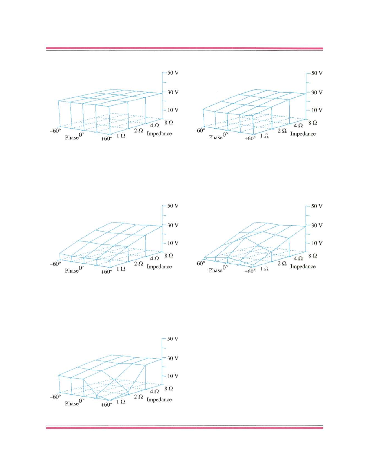
Typical Examples of Amplifier Measurements with The PowerCube
Figure 1: The perfect amplifier that never existed.
Figure 3: An amplifier with a poor power supply.
Figure 5: Severe oscillation with a reactive load.
Figure 2: An amplifier with a good power supply.
Figure 4: Very badly designed current limiting.
The PowerCube seeks a target value of 1% THD at 20
data points. It uses 1 kHz sinewave bursts of 20 ms
duration. In a separate test it also measures instantaneous peak current (one cycle of 10 kHz into 0.1 Ω).
ISSUE NO. 20 • LATE SUMMER 1993
17
pdf 19
Page 20

pendent on frequency are categorized as dynamic linearity errors [Borbely 1989]. Dynamic errors are not more
important than static errors. An amplifier which has a
steady -60 dB harmonic distortion across the frequency
band is not better than an amplifier which has -100 dB
distortion at 20 Hz and -80 dB distortion at 20 kHz.
We use THD tests exclusively to characterize amplifier nonlinearity. Human hearing is not very sensitive
to low-order harmonic distortion, but there is greater sensitivity to nonharmonically related tones, such as those
generated as intermodulation products in distortion tests
using two or more tones. We do not perform such separate IM distortion tests here because they characterize the
same nonlinearities identified by the THD tests. A nonlinearity that gives rise to a high 20 kHz THD will also
cause inband distortion products in a multitone test. A
full-scale 20 kHz test has the advantage that it has the
maximum rate of change of any inband test signal and it
characterizes both even- and odd-order nonlinearities
[Borbely 1989], [Jung 1979]. Transient intermodulation
effects [Otala 1970] are also covered in this test. It has
the disadvantage that the distortion components measured to characterize the nonlinearity are out-of-band. In
Issue No. 18 I pointed out that feedback rates cannot be
increased to reduce 20 kHz distortion as they can be at
lower frequencies because this will lead to stability prob-
lems. Open-loop bandwidth and open-loop distortion
play an important role in determining the closed-loop 20
kHz distortion of an amplifier [Marsh 1985]. As I stated
previously in Issue No. 18, it can be shown using stochastic processes that a nondeterministic music signal responds to a nonlinearity in the same manner as a static
sine wave. The audiophile folklore that sine-wave tests
do not fully characterize the nonlinearity of an amplifier
is just plain wrong. As stated in Issue No. 18, we do not
perform exotic tests such as phase intermodulation distortion because these tests have been shown to be of
questionable value [Cherry 1982], [Cordell 1983]. In a
power amplifier the distortion measurements are made
with the amplifier under load. We performed the dis-
tortion tests under both 8- and 4-ohm loads. None of the
amplifiers reviewed below is designed to source continuous power into a load of less than 2 ohms, so we did not
test them for THD below 4 ohms.
Damping factor is a specification unique to audio
power amplifiers. It is in effect a measurement of the output impedance of an amplifier, being the ratio of an 8ohm load to the amplifier's output impedance. In a mod-
ern amplifier, damping factor at lower frequencies is often greater than 1000. Cable resistance will thus dominate. At high frequencies the damping factor may
decrease. This can be due to reduced feedback rates in
the amplifier, which are the result of dominant-pole compensation or feed-forward compensation [Leach 1988]. It
is more likely, however, to be caused by the presence of
a series inductor at the output of the amplifier, outside the
ISSUE NO. 20 • LATE SUMMER 1993
feedback loop. The purpose of this inductor is to decouple the output stage from a capacitive load. The capacitor would otherwise create a pole in the amplifier's
transfer function, which could lead to poor stability margins or oscillations. Your speaker cable provides series
inductance free, so this will dominate an amplifier which
does not have a series inductor. Please note that tube
amplifiers can have very low damping factors. When a
tube amplifier with a low damping factor is connected to
a high-capacitance (read $100-per-foot) speaker cable
and a difficult speaker load, the frequency response at the
speaker terminals is anything but flat (see your Editor's
article on speaker cable in Issue No. 16). Once again we
see that tube amplifiers can sound different—different,
not better.
MOSFETs vs. bipolar transistors.
Serious designers who believe that MOSFETs are a
better choice for the output stage of a power amplifier are
in a minority, but important thinkers such as Robert Cordell [Cordell 1984] and Erno Borbely [Borbely 1982],
[Borbely 1984] are among their ranks. Let's first dispose
of the tweako cultist dogma. The cultists say MOSFETs
perform more like tubes because they are voltage-drive
devices. Tubes have tremendous disadvantages and no
advantages in a power amp, so this argument can be dismissed without comment. MOSFETs have significantly
higher transconductance (the change in drain current for
a change in gate-to-source voltage) than tubes (but lower
than a bipolar—see below); thus they are usable in an
output stage without a transformer. MOSFETs, unlike
tubes, are available in complementary pairs.
Next, cultists will tell you that MOSFETs are more
linear than bipolar devices. It is true that an unloaded and
undegenerated common-drain MOSFET stage driven
with a voltage source is more linear than an unloaded and
undegenerated common-emitter stage driven with a voltage source, but no serious designer would use an undegenerated common-emitter amplifier in an output
stage. With proper degeneration the bipolar stage will exhibit less distortion than an equivalent stage using MOSFETs. One reason for this is the fact that for a given bias
current the tranconductance of a bipolar will be higher
than of a MOSFET. Another reason is that the nonlinear
emitter-collector output resistance of a bipolar device is
much lower than the source-drain output resistance of a
MOSFET. The open-loop output resistance of a follower
stage is directly proportional to transconductance. The resulting higher output resistance of a MOSFET follower
stage can lead to degradation in stability [Leach 1988] as
well as lower damping factors.
If a MOSFET is used in a source-follower
configuration, it will have significantly higher distortion
than a bipolar device, owing to its lower transconductance and the fact that its transconductance varies
considerably as the drain current changes. As the output
21
pdf 20
Page 21

voltage increases across the load, the output device must
sink more current and the voltage between the gate and
source of the MOSFET must increase in order to supply
the current. The amount of this change is dependent on
the device's tranconductance. The value of the transconductance increases as the current through the device
increases. Thus when the output is near ground, the output device is sinking only a small current. The amount of
gate-to-source voltage change required to move the out-
put 1 V will be higher than when the output is close to
the supply rail and the device is sinking significant cur-
rent. This nonlinear change in gate-to-source voltage
with a constant change in output voltage leads to distortion of the signal. Since bipolar devices have a much
higher tranconductance, the nonlinear change in the base-
to-emitter voltage over output current variations is small,
and less distortion results.
The large variation in transconductance at low
drain currents in MOSFETs leads to significant crossover
distortion, since the total tranconductance of the output
stage is reduced near the center ground level where current in the output stage is low. Overall negative feedback
is not effective in reducing high-frequency crossovernotch distortion [Cordell 1984]. Cordell has demonstrated that the distortion of a MOSFET output stage can be
reduced using an output error correction technique developed by Hawksford. Cordell produced a 50-watt
MOSFET amplifier using the Hawksford technique and
obtained a 20 kHz distortion figure of-105 dB. Caution
must be used with this measurement, since it represents
the result from one low-powered prototype. It does suggest that a scaled-up commercial version of this amplifier
could be a world-beater, but unfortunately nobody has
ever produced a commercial version of the Cordell design.
MOSFET devices have higher on resistance than
bipolar devices because of the lightly doped drain region
of the MOSFETs, which is required so that the devices
will have high breakdown voltages. This reduces
efficiency and increases thermal dissipation. A new device called an IGBT has recently been introduced, which
has lower output resistance for a given die size. In other
respects an IGBT is similar to a power MOSFET and is
manufactured with a modified MOSFET process.
The total voltage required to keep a transistor
turned on is called its forward bias. The high forward
bias of MOSFETs trades away power-supply headroom
and increases power dissipation, which must be addressed by adding additional heat sinks. The problem
gets worse as a MOSFET is required to source current.
Because of its lower transconductance than that of a bipolar device, the additional voltage drop from the gate to
the source becomes much larger when driving significant
current, and this further limits headroom. The principal
parameter that sets the required forward bias voltage of a
MOSFET is the threshold voltage. Bipolar devices have
22
no parameter equivalent to the threshold voltage. MOSFETs are harder to parallel than bipolar devices because
of the large variation in MOSFET threshold voltages.
Complementary pairs of MOSFETs are less wellmatched than bipolar devices, resulting in less cancellation of even-order harmonics in a push-pull stage. This is
because MOSFETs are unipolar majority-carrier devices.
They are either n-channel or p-channel. The n-channel
MOSFETs operate with electrons; the p-channel MOS-
FETs use holes. On the other hand, npn and pnp devices
use both (majority and minority carriers); that's why they
are called bipolar.
A disadvantage of bipolar devices is related to the
minority carriers. In the active region, bipolars accumulate charge in the base. When an output circuit
makes the transition to class B, one of the output devices
should shut off. The turnoff time of the device is delayed
until the minority carriers can be cleared. This can lead to
increased distortion in the crossover region. Designing a
robust predriver stage, so that the minority carriers can
be quickly removed, reduces the distortion effect. Best
results are often achieved if all the predriver stages are
biased to operate in the class A mode. Dynamic outputstage biasing circuits can also be used to eliminate the
distortion due to minority carriers, by preventing any out-
put-stage device from turning off completely. This
scheme is often called sliding class A biasing. The cur-
rent in the output devices is monitored and if it falls be-
low a preset level (at the point where the circuit is going
to go into the class B region), the bias voltage across the
output stage is increased. This prevents any output devices from turning off. The dynamic bias circuit is a nested feedback loop in the amplifier. Problems associated
with making sure the loop is wideband enough for the application and assuring it is stable must be addressed. To
vary the output stage's bias voltage, the bias parameters
of the second gain stage must be varied. This can degrade
performance of the second gain stage. For these reasons,
dynamic bias has apparently not been as effective as had
been hoped and the technique is less popular today than
several years ago.
The collector current of a bipolar transistor has a
positive temperature for a fixed base-emitter voltage.
Thus, as the device gets hotter, it draws more current and
gets still hotter. If the process is allowed to continue, the
device can draw enough current to destroy itself. This
process is called thermal runaway. To keep the quiescent
current of a bipolar output stage stable as the heat-sink
temperature changes, some parts of the bias network that
sets the quiescent current are mounted on the heat sink to
provide thermal feedback. This thermal feedback cannot
respond instantaneously to heating at the power transistor's junction; thus it takes a relatively long time for
the bias to be stabilized, and bias currents can vary significantly as signal conditions vary. Thermal settling
components can be a source of distortion. In addition to a
THE AUDIO CRITIC
pdf 21
Page 22

thermal-tracking bias circuit, an overtemperature sensor
is typically mounted on the heat sink. If the heat sink
goes above a predetermined temperature, the amplifier is
shut down.
Now, MOSFETs are not as sensitive to temperature
changes as bipolar devices. MOSFETs are often claimed
to have a negative temperature coefficient of drain current. While it is true that the current gain of a MOSFET
decreases with temperature, the threshold voltage also
decreases with temperature. Since the current flow
through a MOSFET increases as the threshold voltage
decreases, this component of the current change is pos-
itive with temperature. The actual direction of the temperature coefficient is thus dependent on the way the
MOSFET is biased. In any case, the smaller value of the
temperature coefficient means that MOSFETs do not re-
quire a thermal feedback circuit to stabilize the bias, or
they require only a small amount of feedback. As a result
MOSFET output stages show much smaller amounts of
thermal distortion. Didden uses a circuit which senses the
average quiescent current of the output stage and com-
pares it with a reference value [Didden 1983]. The circuit
then changes the bias voltage if the current is not at the
correct value. This improves thermal stability, since the
current of the output stage is being monitored and controlled directly.
A related phenomenon of bipolar transistors is
called secondary breakdown. Secondary breakdown occurs when a local hot spot develops on the surface of the
device as a result of collector current concentrating on
small areas of the silicon substrate. Current conduction
becomes nonuniform and is concentrated at these hot
spots. This leads to further device heating and eventual
device destruction. The temperature of the case of the
transistor will not show the presence of these hot spots
that cause the device's destruction. The safe operating
area (SOA) of a bipolar is a set of voltage-versus-current
regions as a function of the time for which the bipolar de-
vice will not enter secondary breakdown. Clearly the bi-
polar must be protected from entering these overload
conditions. This protection is the current limiter dis-
cussed above. Properly designed, these protection cir-
cuits can make a bipolar amplifier very reliable. MOSFET output stages do not usually require current limiters;
this allows for reduced production cost. When a local hot
spot occurs in a MOSFET, the area tends to conduct less
current, and this tends to equalize the temperature across
the die.
MOSFET devices are often claimed to be faster
than bipolar devices. Often these comparisons are of the
large-signal switching characteristics of the device. Most
power semiconductor devices are used for switching
functions, not linear amplification. Under these conditions a MOSFET will usually win. Switching characteristics are important in the transition region of a class AB
amplifier, as discussed above, but in a power amplifier
ISSUE NO. 20 • LATE SUMMER 1993
device characteristics in the active region are most important. Here the winning technology is less apparent.
One problem in making these comparisons is that stateof-the-art bipolar devices suitable for power amps are not
readily available in the U.S. Most high-speed, highpower bipolar devices that are available in matched complementary pairs are manufactured in Japan. Advanced
technology, such as ring emitters, is used in these devices. From the limited information I have on these devices, they appear to have band widths equivalent to those
of MOSFETs. Very fast bipolar devices are available but
they have breakdown voltages which are too low for a
high-power amplifier. This can be worked around by
placing a dynamic cascode device at the collector of the
output bipolar device [Didden 1983]. As the emitter of
the dynamic cascode moves with the signal level, it holds
the VCE of the high-speed output device to a low constant
level, preventing breakdown.
Bipolar devices require base current to operate.
One or more predrivers are required to supply this cur-
rent, so that the second gain stage of the amplifier is not
loaded down. MOSFETs do not require base current but
they have very large input capacitance. Designing a
wideband predriver to drive this load can be more
difficult than designing the stage to interface current to a
bipolar output stage. Fortunately, in a source-follower
configuration the gate-to-source capacitor is boot-
strapped, reducing the effective input capacitance of a
MOSFET-follower output stage.
Going to the head of the class.
It is strange that tweaks will dismiss most causes of
static linearity as unimportant, but they are obsessive
about the class of operation of the output stage. In a true
class A amplifier the quiescent current is set large enough
so that it can drive the maximum current demanded by
the load [Gray and Meyer 1984]. In such a configuration
the amplifier is dissipating more power under no-load
conditions than when it is putting out maximum power.
Snyder provides a useful distinction between class A and
class AB amplifiers [Snyder 1990]. A class A amplifier is
limited by its quiescent current, and a class AB amplifier
is limited by the output voltage limits. We have already
discussed some problems with crossover distortion,
which occurs in a class AB amplifier as the amplifier
makes the transition from class A to class B, and have
suggested potential solutions, such as dynamic biasing to
keep all output devices turned on. One formal analysis of
crossover distortion has been undertaken by Sandstrøm
[Sandstrøm 1983]. He notes that in class A operation
both devices are conducting, thus the open-loop output
impedance of the amplifier is the sum of both of the transistors' tranconductances, and when the amplifier is in
the class B mode, with only one transistor operating, the
output resistance doubles. With a load on the amplifier, a
three-section piecewise linear model of the transfer func-
23
pdf 22
Page 23

tion of the output stage is constructed. In this model, the
gain in the class B region is assumed to be a constant and
smaller than the gain of the amplifier in the class A region. This simple model ignores the variation of transconductance with operating current, but it allows analysis. Sandstrøm's model shows that crossover distortion
can be significant. Dynamic biasing will not help, since it
keeps the side of the output stage not driving the load
running at much lower current than the side driving the
load. This side of the output stage has a much lower
transconductance than the side driving the load, and the
Sandstrøm model still applies. As explained above, crossover distortion can be difficult to reduce by the use of
global feedback but can be reduced using the Hawksford
circuit. Feed-forward circuits and current dumping topologies have also been proposed to reduce this crossover distortion. The interesting technique developed by
Wurcer for the AD797 op-amp (see Issue No. 18, page
37) could also be considered, but it may not work outside
a monolthic chip because of matching requirements.
Cherry has identified another distortion mechanism
in class B amplifiers [Cherry 1981]. In an ideal class B
amplifier the current flow into the output transistors is a
half-wave-rectified sine wave. A half-wave-rectified sine
wave contains high levels of harmonics. Mutual inductance between the power supply loop and the signal
path can cause the power supply waveform to couple to
the signal path, causing distortion. Careful attention to
the layout of the amplifier is required to prevent this distortion mechanism from occurring. Snyder has proposed
a balanced class A amplifier circuit which takes constant
current from the supply [Snyder 1990]. In a balanced circuit the load is being driven at both sides. The current required by the two opposing output stages adds to a constant. Unfortunately this property does not hold for class
AB balanced amplifiers. A balanced class AB amplifier
can take advantage of a floating power supply for the output stage [Takahashi 1984]; thus signal-dependent current flow in the output stage is not transferred via ground
to the preceding stages of the amplifier. Takahashi also
shows in his paper that a balanced amplifier will have
lower harmonic distortion independent of the class of its
output stage .
A high-power class A amplifier is simply not practical, although some of these amplifiers have been produced commercially, because it is 25% efficient under
load and dissipates full power as heat under no load. Fortunately, modern designers have been able to reduce the
distortion mechanism in class AB amplifiers to a point
where amplifiers can routinely produce THD-plus-noise
levels below -80 dB.
The past and present.
Progress in the design of power amplifiers is direct-
ly tied to the progress in semiconductor engineering. Early solid-state power amplifiers were designed with un-
ISSUE NO. 20 • LATE SUMMER 1993
reliable germanium transistors. Designers unfamiliar
with transistor circuit design used topologies similar to
tube circuits. They even used transformers in the signal
path. It is likely that some of the early transistor amplifiers sounded worse than the best tube competition. Silicon devices arrived in the middle '60s. Silicon power
transistors were faster and more reliable. Before the development of modern devices, only npn power devices
could be manufactured at reasonable cost. These devices
were slow and had limited breakdown voltages. Output
devices had to be placed in series to handle large voltage
swings. Moving away from transformers, designers developed npn-only quasi-complementary output stages.
These stages had asymmetrical performance parameters
on the positive and negative swings of the output. Unipolar power supplies required output coupling capacitors,
and the power supply rail was bootstrapped at the output
of the second stage to improve output swing. Complaints
about the sound of these amplifiers (they would measure
lousy in our current test regime), the advent of fast complementary output devices, and the development of the
two-gain-stage op-amp (741) topology brought forth a
number of important design innovations in the '70s. Im-
portant contributions were produced by Bongiorno,
Borbely, Carver, Cherry, Cordell, Curl, Garde, Greiner,
Hawksford, Holman, Iverson, Jung, Leach, Meyer, Pass,
Otala, and Takahashi among others. The result of their
work was the modern solid-state amplifier. As a result of
these researchers' innovations, the power amplifier became acoustically transparent, and tube amplifiers were
hopelessly outclassed in all respects.
Table 1 shows the significant design elements of
the power amplifiers in this survey. Other amplifiers in
the table may be reviewed in future issues. I have also included kit designs from A-Train Ltd., Borbely Audio,
New England Analog, and Old Colony Sound Lab. The
Citation 22 which appears in the chart was reviewed in
Issue No. 11. We wanted to include this excellent design
in this survey but according to the manufacturer it will
soon be replaced by a new model. We will be sent a sam-
ple of the new model when it becomes available. One extremely innovative design is the current-feedback amplifier of Mark Alexander [Alexander 1990]. Like the
Cordell amplifier, it exists only as a low-power prototype, and no commercial design is available. It is so sig-
nificantly different that it does not fit easily into the table.
Current feedback, which was discussed in Issue No. 15,
is now often used for I-to-V converters in CD players. Alexander shows that this feedback technique may have
significant advantages in power amps also. He uses
IGBTs in the output stage. Distortion of this amplifier is
low. It happily produces 100 kHz square waves into 8ohm loads. It is very stable into capacitive loads.
It can be seen from the table that most modern
commercial transistor amplifiers are very similar to one
other. Indeed, it is somewhat surprising that most of the
25
pdf 23
Page 24

26 THE AUDIO CRITIC
Table 1: Comparison of Significant Power Amplifier Topologies
Buffer
Stage or
Compound
< Differential Pair > 2nd Stage <
MODEL
A-Train Ltd.
"Ampzilla III"
(no longer offered)
Acurus A250
$850.00
Aragon 4004 MKII
$1850.00
B&K Sonata M-200
$998.00 each (mono)
Borbely Audio
(kit, made in Germany)
Bryston 4B NRB
$2195.00
Citation 22
$1149.00
Cordell
(prototype)
[Cordell 1984]
Didden
(prototype)
[Didden 1983]
Dynaco ST400II
$995.00
Hafler Series 9500
Transnova
$1800.00
New England Analog
(plans only)
PS Audio PS 100 Delta
$1195.00
R.E. Designs LNPA 150
$2700.00 the pair (mono)
Rotel RB-990BX
$1100.00
Sansui
Vintage AU-X911DG
$1250.00
1
Nonlinear load implements soft clipping.
2
The collector of the noninverting side of the differential pair is terminated into
the emitter of the second gain stage. This is a folded-cascode-like topology.
3
Part of a closed-loop feedback amplifier built around the output section.
4
The Hawksford distortion correction circuit is used at the output stage.
5
Dynamic output-bias-current set keeps quiescent current constant under different
load conditions.
6
Diamond Differential (X-cell) configuration biased with floating voltage sources.
Active
Element
Bipolar
Bipolar
Bipolar
Bipolar
Bipolar
Bipolar
Bipolar
Bipolar
Bipolar
Bipolar
JFET
Bipolar
JFET
Bipolar
Bipolar
Bipolar
Complementary
Symmetry
Yes
Yes
Yes
No
Yes
Yes
Yes
No
No
Yes
Self-biased
Yes
Yes
Yes
Yes
Yes
6
Biased by
Current
Source
Yes
Yes
Yes
Yes
Yes
No
Yes
Yes
Yes
Yes
Yes
Yes
Yes
No
Yes
Yes
Cascode
Stage
No
Yes
Yes
Yes
No
No
Yes
Yes
Yes
No
Yes
Yes
Yes (dynamic bias)
No
No
No
Load
Resistor
Resistor
Resistor
Active
Resistor
Resistor
Resistor
Active
Resistor
Resistor
Resistor
Resistor
Resistor
Resistor
Resistor
Resistor
No
No
Yes
Yes
Yes
No
Yes
Yes
No
No
No
Yes
Yes
No
No
No
Active
Element
Bipolar
Bipolar
Bipolar
Bipolar
Bipolar
Bipolar
Bipolar
Bipolar
Bipolar
Bipolar
Bipolar
Bipolar
Bipolar
Bipolar
Bipolar
Bipolar
pdf 24
Page 25

(Not restricted to, nor including all, power amplifiers reviewed in this issue.)
Regulated Output Number
Supplies Predriver and Type
on V Gain Stage(s) of Output
Second Gain Stage > Stages and Type Devices <—Coupling Capacitors—> Protection
Cascode
Stage
No
No
No
No
No
2
No
No
Yes
Yes
No
Yes
No
No
No
2
No
No
Load
Active
Active
Active
Active
Active
Active
Resistor
Active
Resistor
1
Active
Output
stage load
2nd stage
Resistor
Resistor
Active
Active
Active
Push-Pull
Yes
Yes
Yes
No
Yes
Yes
Yes
Yes
No
Yes
Yes
Yes
Yes
Yes
Yes
Yes
No
No
No
No
No
Yes
No
Yes
Yes (dynamic cascode on
output stage)
No
Yes
Yes
No
Yes (output
stage also)
No
No
2
Bipolar
1
Bipolar
1
Bipolar
None
1
MOSFET
3
Bipolar
3
2
Bipolar
3
Bipolar
2
Bipolar
1
Bipolar
None
1
Bipolar
1
Bipolar
1
Bipolar
2
Bipolar
2
Bipolar
3 per side
(balanced)
Bipolar
4
Bipolar
4
Bipolar
1
MOSFET
1
2
MOSFET
4
Bipolar
4
Bipolar
1
MOSFET
4
4
Bipolar
5
4
Bipolar
4
MOSFET
4
Bipolar
2
Bipolar
2
Bipolar
5
Bipolar
1 per side
(balanced)
Bipolar
Nonpolar
electrolytic
Electrolytic
+ film byp.
No
No
Film
Film
Electrolytic
Film
Film
Electrolytic
+ film byp.
No
No
No
No
Electrolytic
No
C
2
No
(DC servo)
Electrolytic
+ film byp.
NP 'lytic +
film bypass
No
(DC servo)
No
(DC servo)
Electrolytic
No
No
No
(DC servo)
Electrolytic
+ film byp.
Electrolytic
+ film byp.
No
(DC servo)
No
Electrolytic
+ film byp.
Electrolytic
No
A
A, B, C, I
A,B,E
?
A
B, D,I
B,F, I
?
H,I
A, B, C, I
A
D,I
B,G,I
A
A,B,I
E,F
Protection
A—DC rail fuses
B—Thermal sensing
C—Second-stage current limiting
D—Output-stage current limiting
E—DC input sensing
F—Excess input sensing
G—Output fuse in feedback loop
H—SOA monitor circuit (analog)
I—Output diodes to block inductive kick
NOTE:
The purpose of this table is simply the comparison
of circuit features, not the establishment of criteria
for evaluation. Please do not make the mistake of
trying to derive a "figure of merit" for an amplifier
from these data; that is not possible because the
entries in the table do not necessarily represent
right or wrong, better or worse, design solutions.
ISSUE NO. 20 • LATE SUMMER 1993 27
C
1
pdf 25
Page 26

commercial amplifiers have topologies similar to that of
Dan Meyer's 1973 Tigersaurus. This highly innovative
amplifier, like the first commercial jet aircraft, the Comet, had major design weaknesses and, like the Comet,
came to an early and catastrophic end. Note that none of
the amplifiers in the table use sliding biasing, feedforward error correction, or current dumping. The Sansui
is the only production amplifier in the table to have fully
balanced outputs. Only the B&K and Hafler amps use
MOSFETs. Below are the complete reviews of these
amplifiers. Aspects of the design of the individual amplifiers are discussed in the individual reviews. References
to capacitors in the signal path are based on the following
basic schematic (see also Issue No. 18, page 18):
Figure 6: Capacitors in the signal
path of a power amplifier.
Boulder 500AE
Boulder Amplifiers, Inc., 4850 Sterling Drive, Boulder, CO
80301. 500AE stereo power amplifier, $3999.00 (international
version, $4099.00). Tested sample owned by The Audio Critic.
The original Boulder 500 was reviewed by the Editor in Issue No. 10. The 500AE is essentially the same
amplifier minus the bells and whistles—one instead of 18
indicator lights, no input attenuators, balanced inputs
only, no handles in the back. The sample we tested had
been updated by Boulder in October 1990 and represents
the current version.
This is the costliest amplifier so far in our survey,
and it also turned out to be the best-performing amp
within its power range in this group. I would love to tell
you every detail on how they did it, but Boulder would
not submit a schematic. They say it's based on the JE990 topology [Jensen 1980], which is equivalent to saying it's based on the 741 op-amp. The mundane 741 has
the same topology as the 990. This topology consists of a
single differential pair with active current mirror and current-source bias. The differential pair is connected to a
emitter follower followed by a degenerated commonsource amplifier biased by an active current source. A
single-stage complementary emitter follower forms the
output stage. The compensation network for the JE-990
is its most interesting feature. The dominant pole is
28
formed in the traditional manner with a Miller compensation network on the second gain stage, but other compensation components are novel. Small inductors are
placed across the degeneration resistors of the differential
stage. The Vth (slewing threshold) of the differential stage
can thus be made larger without degrading noise performance. The second-order RC network across the second-stage emitter degeneration resistor is also uncommon. Now simply scaling this up to make an
ultralow-distortion power amp is not going to work.
First, the output stage is going to be much more complex,
with one or more stages of predrivers to drive significant
power to the load. It is also hard to believe that the second gain stage in this amplifier, which swings almost
from power rail to power rail, would not be a complementary design to cancel even harmonics. If it is indeed
single-ended, it is almost certainly cascoded. A distortion
mechanism in Miller-compensated power amplifiers
[Gunderson 1984] would also have to be addressed. It is
likely that some novel circuit tricks are used that the
company wants to keep proprietary. That must by why
the company does not want to give out a schematic.
The amplifier has an unusual system topology, with
two separate closed-loop gain blocks. The first gain block
has 18 dB of voltage gain. The second gain stage is said
to be a scaled-up version of the first. Both stages are said
to be direct-coupled, with DC servos used to reduce offsets. The manufacturer claims to have developed a complex method of safe operating area (SOA) protection.
The system is said to make instantaneous power measurements of the output transistors by measuring the voltage across them and the current flowing through them.
Such a system would not trip inaccurately in the presence
of reactive loads. Heat sink temperature is also claimed
to be considered before the amplifier is shut down.
The build quality and complexity of the 500AE
reflect why this amplifier costs $3999. The chassis construction is of high quality, with a look comparable to the
amplifier's competition. Thick metal is held together
with machine screws. Along the two sides of the amplifier there is a staked pair of large PC boards stuffed
with mil-spec or near-mil-spec components. The PC
boards are high-quality double-sided boards with through
holes. All the components are required because of the
amplifier's two-stage design and its complex protection
circuitry. The heat sinks containing the output transistors
are directly beneath the PC boards on each side of the
amplifier. Separate sheet metal is used to house the amplifier's large primary filter capacitors. The amp has added
circuitry to prevent destructive inrush currents on power
up. A single large toroidal transformer and full-wave rectifier supply power for both channels. The amplifier retails for $100 more if a multivoltage international transformer is required. No information is supplied as to the
existence of any power-supply regulation in the 500AE.
The inputs accept only XLR-type balanced connectors.
THE AUDIO CRITIC
pdf 26
Page 27

The most remarkable attribute of this amplifier is
that the static THD-plus-noise numbers are dominated totally by noise. Into an 8-ohm load the 500AE reaches a
minimum THD-plus-noise level of-100 dB at 150 watts
for a 20 Hz signal. Into 4 ohms the minimum THD-plusnoise level at the onset of clipping is -100 dB at 260
watts. Dynamic distortion occurs above 10 watts, limiting at -94 dB into both 4 and 8 ohms. Dynamic distortion effects are strangely visible on both the 1 kHz and
20 kHz curves. (Remember—dynamic distortion is not a
greater fault than static distortion as long as the figures
are low for both, as they are here.) At clipping the 1 kHz
and 20 kHz distortion is -87 dB.
The PowerCube system measured a dynamic output voltage of 37 volts (170 watts) at 8 ohms. This corresponds to the steady-state distortion of the amplifier;
thus the 500AE has no dynamic headroom at 8 ohms.
Only under a 1-ohm load did the voltage decline significantly. There a maximum voltage of 33 V was measured at -60° phase. A minimum of 26 V was measured
at +30° phase. Given the limited information we have on
this amplifier, the cause of this variation remains a mystery. Boulder literature makes a big deal of the amplifier's large phase margin, but the above result makes us
wonder. Peak current output was 135 amps. Damping
factor is reduced significantly at higher frequencies because of the presence of a series inductor, which improves stability at high frequencies.
So, what we have here is an amplifier that produces
lower distortion than any other commercially available
amplifier known to me. But achieving this performance
requires very complex circuitry and hence high cost,
namely $3999. In addition, the amplifier can put out only
170 watts into 8 ohms. It does behave like an almost perfect voltage source; thus it will produce very large
amounts of power into low-impedance loads. By comparison, the Rotel RB-990BX (see below) is roughly onefourth the price and 50% more powerful, but it produces
ten times the dynamic distortion of the Boulder and is not
as well built. (At -70.5 dB the Rotel's worst-case distortion still is vanishingly small.) If you have a Mercedes
in your driveway, you can justify a Boulder 500AE in
your living room, otherwise the Rotel will do just fine.
On the other hand, if you have a perfectly restored Ford
Model T in your garage, you might want to try a megabuck tube amp. The relationship between the performance of the antique Ford and a Mercedes is similar
to relationship between a $10,000 tube amplifier and the
Boulder 500AE.
Bryston 4B NRB
Bryston Ltd., 57 Westmore Drive, Rexdale, Ont., Canada M9V
3Y6. Model 4B NRB stereo power amplifier, $2195.00. Tested
sample on loan from manufacturer.
This is another example of the excellence of Brys-
ISSUE NO. 20 • LATE SUMMER 1993
ton engineering. Construction is of the same high standard we found in the Bryston preamps. In the power
amplifier, double-sided PC boards with through holes are
used. Only the pot used to adjust the bias current looks to
be of substandard quality. When I pointed the pot out to
Chris Russell, the amp's designer, he responded that it
worked well in the amplifier and had never failed. It is
hard to argue with well-reasoned facts. As one would expect at this price point, the amplifier is built with thick
sheet metal held together with machine screws.
The 4B NRB is dual mono past the line cord. Separate power transformers drive 35A bridge rectifiers,
which then drive 15,000 µF of filter caps per supply rail.
Electronics for balanced-to-single-ended conversion and
amplifier bridging option (for mono operation) consist of
the same discrete op-amp as used in the Bryston preamp.
Many of Bryston's competitors use cheap op-amps for
these functions. The input signal is capacitively coupled
with a film capacitor. An electrolytic cap is used in the
ground return path of the main feedback loop (capacitor
C2 in Figure 6).
The amplifier's input stage consists of a pair of
complementary differential pairs without any degeneration. The second stage is a complementary common-source amplifier with emitter degeneration. As in
the Bryston preamplifier, the differential pairs are biased
with resistors, not current sources. More surprisingly,
there are no circuit additions to reduce the effect of the
nonlinear base-emitter junction capacitance of the second
gain stage. Normally an emitter follower buffers the first
gain stage from the second, and/or the second gain stage
is cascoded. This is required because the voltage swings
at the collector-base junction of the second stage of a
power amplifier are rather large, coming close to the
power supply rails of the amplifier when it is delivering
full power. This results in significant variation of the collector-base junction capacitance. If the second stage is
not buffered from the first, the nonlinear capacitance will
result in a change in the amplifier's high-frequency openloop gain as the output of the second stage moves across
its voltage range. This leads to dynamic distortion [Cherry 1982], [Cordell 1980], [Borbely 1989]. The disadvantage of the follower stage is that it introduces another open-loop time constant, which can degrade the
amplifier's closed-loop performance. Bryston was able to
eliminate the need for the emitter follower by using the
same technique as in their preamplifier. Second-order
distortion is reduced by minor circuit changes, such as
unconventional bias currents and simple passive circuit
additions.
Supply voltage regulation is in the amplifier's first
two stages to increase power-supply rejection ratio and
desensitize these stages to supply-rail variations that occur as the amplifier is required to source or sink large
amounts of current. A zener-diode shunt regulator is employed. These circuits can work on a lower-voltage sup-
29
pdf 27
Page 28

ply rail than the output stage, without reducing the amplifier's output swing, because the final stage of this ampli-
fier has a gain of 3. The required voltage swing of the
second stage is thus reduced by a factor of 3 and it re-
mains well within the regulated supply rails.
Adding gain to the output stage of a power amplifier is a nontrivial matter because of stability issues
which occur when an amplifier has more than two voltage-gain stages. The amplifier can also become more sensitive to reactive loads. So, while Bryston's competitors
were adding Wonder Caps to tube circuits developed during World War II, Chris Russell and his staff had to
create a new output topology for the 4B. To keep the output circuit stable and set to its desired gain, nested feedback was chosen for the 4B. In addition to supplying
voltage gain, another goal of the Bryston output stage
was to reduce distortion in the crossover region resulting
from mismatches between the complementary pnp and
npn devices. The complete output topology used by Bryston is very clever and quite complex. The amplifier's output terminal is connected to two different transistor stages
in parallel. One stage is a common-emitter topology, the
other a common-source topology. Three stages of predrivers precede the final output stage electronics to reduce loading on the second gain stage. Bryston has a nice
two-page technical description of the output stage, including schematic. To save space here, I direct interested
readers to the Bryston publication. (Now, if other manufactures would produce literature as detailed as Brys-
ton....) The actual circuit has an additional predriver
stage, which is not shown in the simplified schematic. A
rather complex current limiter is used for the output
stage, but this is not shown in the Bryston document. In
addition, the output stage is cascoded in the 4B to reduce
the VCE of the transistors by a factor of 2. This is accomplished by applying to the base of the cascodes a
voltage which is proportional to the amplifier's output
signal. The smaller Model 3B has lower power-supply
rails and does not use the cascode stage. A total of 28
transistors per channel is used to implement the power
amplifier, with an additional 16 devices used for the balanced input and bridging circuits.
Compensation is principally accomplished by
creating a dominant pole at the second gain stage with a
single capacitor to ground. The complete compensation
network topology shows more Bryston innovation, but its
operation is proprietary, so I cannot discuss it here. A 2
µH inductor is in series with the output to prevent the
amplifier from going unstable when loaded by excessive
capacitance. Damping factor at high frequencies is reduced by the presence of this inductor. A relay clamps
the output of the second stage to ground on power up.
The relay releases when the amplifier is stable. A separ-
ate circuit, consisting of a special-purpose integrated cir-
cuit, an op-amp, an SCR, and an optocoupler, slowly
ramps up the line voltage to the amplifier on power up.
30
This ensures that components will not be damaged by inrush currents. The need for this circuit becomes clear
when you realize this amp is warranted for 20 years. The
approach is more sophisticated than switching in a resistor in series with the power line, as done in the more
expensive Boulder 500AE. Thermal breakers are in series
with the Bryston's power line for protection against excessive temperature. The only fuses are external line fuses.
Into an 8-ohm load the Bryston 4B NRB reaches a
minimum THD-plus-noise level of -96.5 dB with a 1
kHz input and -94 dB with a 20 Hz input, both at 250
watts. At this point the amplifier clips, so this measurement is dominated by noise. The Boulder 500AE
achieves an even lower minimum level because it has a
lower noise and hum level. Into 4 ohms the minimum
THD-plus-noise level of the Bryston at the onset of clip-
ping (400 watts) is -88 dB at 1 kHz and -83 dB at 20 Hz.
Above 5 watts dynamic distortion becomes evident, with
the 20 kHz distortion curve flattening out and reaching a
minimum of -86 dB with an 8-ohm load. The 20 kHz
distortion then rises to a preclipping level of -83 dB. Into
a 4-ohm load the 20 kHz distortion curve is again just
about flat between 5 watts and clipping, reaching a minimum of -81 dB. While the overall distortion performance is good, and is better than specified by Bryston,
it is somewhat disappointing given the technical sophistication of the circuit. The PowerCube system measured a dynamic output voltage of 52 V (338 watts) at 8
ohms. This corresponds to 1.3 dB of dynamic headroom.
The PowerCube showed that the maximum voltage output of the amplifier declined by 34% into 2 ohms and
56% into 1 ohm. The current limiter was reasonably
well-behaved, since output varied 3% to 17% across the
five phase angles in each of the four tests. Peak current
output was 52 amps.
As will be seen from the Rotel review below, a
power amp with performance similar to that of the Brys-
ton 4B NRB can be had for half the price. What you get
for twice the price is build quality that allows the unit to
be warranted for 20 years. More important, you get a de-
sign which is bulletproof enough to withstand the rigors
of professional sound-reinforcement work. In such an application, down units are simply not acceptable. As an
example of this, we accidentally drove the amp into clipping with a 100 kHz signal while it was connected to a 4ohm load. After replacement of the external power fuses,
the amp worked perfectly. If a dead amplifier is not ac-
ceptable to you, you should seriously consider this unit.
Dynaco Stereo 400 Series II
Dynaco, a division of Panor Corporation, 125 Cabot Court,
Hauppauge, NY 11788. Stereo 400 Series II power amplifier,
$995.00. Tested sample on loan from manufacturer.
Those of you over 30 no doubt remember the name
THE AUDIO CRITIC
pdf 28
Page 29

Dynaco. The company produced low-cost kits that represented good value at the time. Dynaco products were
marketed as close-to-the-best-for-less. Most owners of
Dynaco products probably remember them less than
fondly. It did not take long for a Dynaco to develop noisy
switches and controls, and for the gold-colored face plate
to tarnish. On the other hand, this most successful marketer of mass-market kits was no doubt responsible for
kindling an interest in electronics in a great many teenagers. The old Dynaco company is long out of business.
With the advent of modern construction techniques, it
costs more to produce a kit than a built unit. Even Heathkit, which held on for several years after Dynaco, has recently stopped producing kits. Why then Panor Corporation has decided to revive the company's name as a
manufacturer of relatively expensive audio components
is unclear to me. Maybe they figured that the name still
had some recognition in tube equipment, which is what
they came out with first. The Stereo 400 Series II is their
first new solid-state product. My evaluation of the product is of course independent of its name.
This Dynaco amplifier is a conventional design.
Complementary differential pairs biased by current
sources form the first stage. The differential pairs are degenerated, but the degeneration resistors are bypassed
with capacitors. This method of introducing a transmission zero into the forward path as part of the compensation network is strange, since the nonlinearity of the
first stage at high frequencies is increased. The same
method of widebanding a differential stage was used by
Otala in one his early designs [Lohstroh and Otala 1973],
but it is unclear if he would still recommend it. (Note that
Boulder does just the opposite, placing an inductor across
the degeneration resistor.) The second stage is a complementary common-source amplifier with emitter degeneration. As in the Bryston, there are no circuit additions to reduce the effect of the nonlinear base-emitter
junction capacitance of the second gain stage. No novel
circuit tricks to reduce this effect can be seen in the schematic. The second stage is followed by a complementary
source-follower predriver. The final output stage consists
of a complementary source follower, the active stage being realized with four bipolar devices in parallel. The
output stage is biased by a two-transistor VBE multiplier.
The output of this stage is connected to the speaker terminal through a series inductor. High-frequency stability
is improved at the cost of some reduction in highfrequency damping factor. Current limiting occurs on the
second voltage-gain stage. The principal action of the cir-
cuit would appear to be to prevent damage to this gain
stage when the latter is near clipping. Total transistor
count per channel, including paralleled devices, is 28.
Compensation is principally accomplished by creating a
dominant pole at the second gain stage with a pair of capacitors to ground at each side of the VBE multiplier. A
470 µF electrolytic cap is used in the ground-return path
ISSUE NO. 20 • LATE SUMMER 1993
of the main feedback loop (capacitor C2 in Figure 6). Another 22 µF electrolytic capacitor is used at the input
(C1). Both electrolytics are bypassed with film capacitors.
The output stage of the amplifier is protected by supplyrail fuses. The bias current to the differential pairs is removed on thermal overload.
The death of the electronic kit is clearly understandable when you see how this unit is put together, using modern construction technology. Almost everything
is mounted to the PC board, and very little point-to-point
wiring is identifiable. The little handwork that is required
is done with the highest professionalism one expects in
onshore assembly. Solder joints are well-flowed, and
shrink-wraps are used on all coax cables. Components on
the PC board are mostly machine-inserted and soldered.
The PC board is double-sided with through holes. A single toroidal transformer is shared by both channels. One
diode bridge is shared by both channels. The primary
filter caps are 24,000 µF. The transformer and heat sinks
are significantly smaller than on the similarly priced Rotel. Predrivers on the PC board also have very small heat
sinks. A front-panel switch reconnects the secondary
winding of the transformer. This is called the highcurrent mode. The transformer's output voltage is lowered, but its series losses are also reduced in this mode.
More power may be available to a low-impedance load in
the high-current mode. The overall build quality of the
unit is not up to the standards of the costlier Boulder and
Bryston. The cabinet is made of relatively thin metal. It
is held together with cheap sheet-metal screws. We were
unable to reseat some of the top-plate screws after they
had been removed. Component quality is not always milspec, but no component appears to be underspecified.
Into an 8 ohm load the ST400II reached a minimum THD-plus-noise level of -86 dB at the clipping
point of 205 watts with a 1 kHz input. The 20 kHz distortion deviated from the 1 kHz curve even at 10 mW.
The minimum level of 20 kHz distortion just before clipping was no better than -68 dB. It is not clear why this
result was substandard; perhaps the problem is due to the
compensation components discussed above. The 4-ohm
measurements were made with the transformer in the
high-current mode. Into 4 ohms the minimum distortion
level at the onset of clipping was -82 dB. The left channel clipped cleanly at 180 watts. The right channel had a
softer clipping characteristic, starting at 120 watts. The
20 kHz numbers were again much higher at all power
levels. The minimum level before clipping was -62 dB.
The PowerCube measurements were always better in the
normal-current mode and thus are the ones reported here.
A dynamic output voltage of 54 volts (364 watts) at 8
ohms was measured. This represents a dynamic power
headroom of 2.5 dB. The voltage declined 14% into 4
ohms, 57% into 2 ohms, and 79% into 1 ohm. Into a resistive load, the dynamic power at 1 ohm was 126 watts.
Peak current output was 17 amps in both transformer po-
31
pdf 29
Page 30

sitions.
The dynamic power measurements of the ST400II
appear to show that the design is underbuilt. Construction
quality of the unit appears to confirm this. The 20 kHz
distortion figures are also high throughout the power
band. For $105 dollars more the Rotel unit (see below)
handily outperformed the Dynaco—in some cases by an
order of magnitude! We thus cannot recommend this unit.
Hafler Series 9500 Transnova
Hafler, a division of Rockford Corporation, 648 River Street,
Tempe, AZ 85281. Series 9500 stereo power amplifier,
$1800.00. Tested sample on loan from manufacturer.
This is the only power amp in this survey to use a
MOSFET output stage. Indeed, this is the only power
amp in the survey to use FETs of any kind. (In truth,
however, I do not know what devices are used by Mr.
Yee in the UltrAmp). The Hafler marketing department
has been pushing the MOSFETs-are-like-tubes angle in
their advertising. This sullies the fine work of Jim Strickland, who is following in the path of Erno Borbely.
Borbely was an early employee of Hafler (long before it
was taken over by Rockford) and had a preference for
MOSFETs for good scientific reasons (see above).
As stated above, the distortion characteristics of a
MOSFET used as a source-follower output stage will be
higher than those of a comparable bipolar stage. One way
around this is to use the MOSFET in a common-source
configuration. Headroom is also significantly improved
with the common-source configuration. However, there
are several problems with that approach. The most significant of these is the problem of biasing the devices.
Traditional VBE multiplier configurations cannot be used
because the biasing loop now includes the power supplies. Any variation in the power supply now affects the
output quiescent current. This problem has been attacked
numerous times in CMOS integrated circuits. The solution usually involves the addition of a complete error
amplifier around each output transistor. The error amp
sets the quiescent current of the transistor and defines its
gain. Assuming that each error amp sets the same current
in both sides of the complementary pair (additional circuitry is often required to ensure this assumption is valid), the quiescent current of the output is set. Jim Strickland's solution to this problem is much simpler but far
less obvious. His innovation is a dynamic power supply.
Here is how it works. Both sources of the complementary
MOSFETs are connected to ground. The gates of the
MOSFETs can now be biased and driven by the second
stage in the standard manner. A stacked diode array in series with the collectors of the second-stage transistors
sets the fixed voltage difference across the gate transistors, thus establishing the quiescent current. Now the
drain of the p-channel output-stage MOSFET is con-
nected to the positive supply rail and the drain of the n-
channel MOSFET is connected to the negative supply
rail. Think about this for a second—what happened to the
positive output terminal of the amplifier? It's at the center tap of the power transformer! What happens in the
amplifier is that as the output moves the transformer secondary, the full-wave rectifier moves and the powersupply filter capacitors move. The whole power supply
follows the output signal! Clearly this amplifier cannot
be described as direct-coupled.
With the bias problem solved, the next issue to deal
with in a common-drain amplifier is the output stage's
voltage gain. With three stages of voltage gain, there will
be three high-frequency poles and lots of open-loop gain
[Grebene 1984]. This is a recipe for an oscillator, not an
amplifier. The solution used in the Hafler is to use a nested feedback loop in the output stage [Grebene 1984].
This loop is formed by a resistor between the output terminal and the gate of the output stage. This local shunt
feedback loop stabilizes the output stage's transresistance
[Gray and Meyer 1984]. Another problem with a common-drain output stage is that it has a very high output
impedance [Grebene 1984]. This makes the gain of the
stage and its high-frequency transfer characteristic highly
dependent on the value of the amplifier's load. The afore-
mentioned shunt feedback loop lowers the effective out-
put impedance of the stage to help reduce this problem.
The amplifier's name, Transnova, apparently is a reference to the output stage's transresistance property. The
shunt feedback also reduces the input impedance of the
output stage. Since the second gain stage has a highimpedance output, the voltage swing at the input to the
output stage is limited. This allows the first and second
stage to run on 24 V regulated rails. Power MOSFETs
have large values of gate-to-source capacitance. When
wired in a source-follower configuration this capacitance
is bootstrapped, lowering its effective value. In the common-source configuration the capacitance is Millermultiplied. This creates a difficult load for the second
gain stage to drive.*
*Much of my statements (with supporting references) in this paragraph will be found to be in contradiction to a paper by Cherry [Cherry and Cambrell
1982]. In his paper a formal analysis of both common-emitter and emitter-follower amplifiers is under-
taken. From mis mathematical analysis Cherry concludes that the stability of an amplifier with a
common-emitter output stage should be very similar
to that of an amplifier with an emitter-follower output
stage when a load is attached. Other amplifier characteristics, including output resistance and distortion,
32
are also claimed to be similar. This runs counter to
my experiences, and I believe that Cherry's analysis
may be flawed because of the simplification required
to produce usable analytical results.
For example, the emitter-follower amplifier model used by Cherry does not include any predriver
stages, causing a significant fraction of the load impedance to be reflected to the second gain stage. Another example is that the parasitic capacitor across
the output device in the common-emitter amplifier is
analyzed by replacing it with a Miller-multiplied ca-
pacitor at the input to the third stage. This capacitor
also gives rise to a right half-plane zero [Gray and
Meyer 1984], a further source of stability problems,
but this zero is not considered in the Cherry paper.
Cherry also claims that nested feedback around the
third gain stage does not improve stability or enhance
performance.
Professor Cherry is one of the seminal thinkers in
audio, so he is not very likely to be wrong. I would
therefore welcome any of our technical readers to
comment on his paper.
THE AUDIO CRITIC
pdf 30
Page 31

The front end of the Series 9500 is more conventional than its output stage. Complementary differential
pairs with JFETs form the first stage. The n-channel
sources are connected to the p-channel sources through a
resistor. Because the JFETs have a negative threshold
(for the n-channel device), this arrangement self-biases
the differential pairs. Unlike a constant-current biasing
scheme, the current in the differential pair can increase
when the differential pair is driven with a large differential current. This improves large-signal dynamic
performance. A similar circuit was developed by Sansui
[Takahashi and Tanaka 1984] using bipolar devices but
is much more complex because the bipolar will not selfbias. The second stage is a complementary commonemitter stage. Both the first and second stage are cascoded with bipolar devices. There is a total of 19 transistors, including the quadruple paralleled output devices.
Feedback is taken from the positive terminal of the am-
plifier (the transformer's center tap) back to the non-
inverting differential-pair input, using the standard passive resistor divider. A 220 µF electrolytic cap is used in
the ground return path of the main feedback loop (capacitor C2 in Figure 6). It is bypassed with a small film
cap. The amplifier's dominant pole is formed by a Miller
capacitor around the second gain stage. Additional secondary compensation circuits are used throughout the
amplifier. They are required keep the three-gain-stage to-
pology stable.
A single huge transformer is used in the Series
9500. Each channel has its own secondary, which is connected in the dynamic configuration described above.
The supplies are filtered with 20,000 µF capacitors, each
paralleled with a 4.7 µF film capacitor. The first and second stages are driven by ±24 V regulated power supplies.
The low power-supply rails can be used because the output stage has voltage gain. The regulated supply starts
with a button-sized full-wave rectifier. 1000 µF capacitors filter the rectifier's output. LM317 and LM337
integrated rectifiers are used to generate the regulated
rails. This supply is shared by both channels. I was somewhat surprised that separate regulators were not used for
each channel. Owing to the more robust nature of MOSFETs, the only protection devices on the amplifier are the
power-line fuse and fuses in the dynamic supply rails. A
turn-on delay circuit prevents current flow in the differential pairs until the output stage has settled.
Construction quality of this amplifier is excellent.
Thick sheet metal is held together with high-quality machine screws. Custom-designed heat sinks start at the
side of the amplifier and then curve to the back. Doublesided circuit boards are stuffed with high-quality components. A large metal bar is placed across the inboard
side of the output devices to ensure good mechanical
contact with the heat sinks.
Given all the innovations in this amplifier, I was
hoping to see static distortion numbers that would rival
ISSUE NO. 20 • LATE SUMMER 1993
those of the Boulder 500AE, Bryston 4B, and Bob Cordell's MOSFET design. It turned out this was not going
to occur. Into an 8-ohm load the 990 reaches a minimum
THD-plus-noise level of -81 dB at 240 watts with a 1
kHz input. Into 4 ohms the minimum distortion level at
the onset of clipping (400 watts) is -77 dB. At 0.55 watts
the 20 kHz distortion curve reaches a minimum of -70
dB, then rises and plateaus, reaching -60 dB at clipping
into 8 ohms. Into a 4-ohm load the 20 kHz distortion
reaches a minimum level of -67 dB and rises to -57 dB
at clipping. The origin of the relatively high 20 kHz distortion is unclear. It may arise from the dynamic power
supply, or it could be an indication that the second stage
is having trouble driving the capacitive load of the output
stage. The 10 kHz square-wave response into a 6-ohm
load with a capacitive component of -45° showed more
than average overshoot and lots of ringing. Capacitiveload square-wave testing of an amplifier with an inductor
in the output stage is not revealing of amplifier instability
because the LC resonance dominates the amplifier's response. This amplifier does not have an inductor in the
output stage, but the transformer is of course inductive.
The value of this inductance and the value of the large
bypass capacitors would not cause ringing at the rate observed in this test. As stated above, stability problems are
more likely in a three-stage design.
The PowerCube system measured a dynamic out-
put voltage of 55 V (378 watts) at 8 ohms. That repre-
sents 1.8 dB of dynamic headroom. The PowerCube
showed that the maximum voltage output of the amplifier
declined by 20% into 2 ohms for noninductive loads and
by 45% into 1 ohm. The dynamic power into a 1-ohm resistive load measured 894 watts. Available output voltage increased into reactive loads; thus no stability problems were identified in the PowerCube tests. No I-V
current limiter artifacts were observed because the Series
9500, like most MOSFET amps, does not require an I-V
current limiter. Peak current output was 71 amps.
I wanted this amplifier to be recommendable, given
all the innovative circuitry and good build quality for the
money. The 20 kHz distortion and some evidence of lower stability margins into capacitive loads militate against
such a recommendation. For only 1.7 dB more cash
($395, that is), the Bryston gives you 20 dB less 20 kHz
distortion, the same level of construction, the same maximum power, and balanced inputs. I hope Jim Strickland
can overcome the remaining design problems of his
topology in the next generation of this product. In the
meantime, does anybody out there want to produce a
scaled-up version of Bob Cordell's state-of-the-art MOSFET power amplifier?
R.E. Designs LNPA 150
R.E. Designs, 43 Maple Avenue, Swampscott, MA 01907. LNPA
150 monoblock power amplifier, $2700.00 the pair. Tested sam-
33
pdf 31
Page 32

pies on loan from manufacturer.
This is a new and very small company. The prod-
uct is advertised in the classified advertising pages of Au-
dio magazine. The LNPA 150 is a monoblock design,
differing from other amps in this survey and almost all
power amps in general in that it has all electronics, including the output stage, on regulated rails. This is a very
expensive undertaking, since what we have here is in es-
sence one power amplifier (the regulated power supply)
driving another power amp. The design of the regulated
amplifier is somewhat simplified, since it needs only to
source (sink) the positive (negative) supply voltage. The
maximum power that must be dissipated by the regulator
is limited to the product of two quantities: maximum current to be delivered to the load times the difference between the unregulated and regulated supply rails. The
output stage devices may be required to dissipate power
which is equal to the load current times twice the regulated rail voltage. The advantage of a regulated supply is
that the amplifier is independent of supply-line variations
and power-supply noise. The power-supply rail does not
change value under changes in load conditions. The disadvantage, beyond significantly increased cost, is the loss
of any dynamic headroom. Except for independence
from power-line variations, these advantages can be
gained by regulating only the voltage-gain stages of the
amplifier. Such regulators (used by Hafler and Bryston)
are much simpler to design because they are not required
to source significant current. Didden has shown that
dynamically varying the output-stage power supply can
actually be advantageous, since the maximum VCE on the
devices is limited and higher-speed output devices can be
used [Didden 1983].
Separate transformers and bridge rectifiers are used
for the positive and negative supply rails of the amplifier.
The unregulated filter capacitor is 33,000 µF. The voltage references for the supply regulators are LM317/337
devices. The regulator is formed with an LM343 op-amp
and a discrete triple emitter-follower output stage. 100
µF capacitors are used on the regulated rails.
The actual amplifier is mostly conventional. Essentially, the much less expensive Rotel (see below) uses
a scaled-up version of the same topology—and produces
a lot more power. Complementary differential pairs are
biased with a resistor and are not degenerated. The out-
put of the differential pairs is then connected directly (no
emitter follower is used as a buffer) to a complementary
common-emitter stage with emitter degeneration. The
principal novelty of the design is the termination of the
collector of the differential-pair transistor—the one that
has its base connected to the inverting input of the amplifier—into the emitter of the second gain stage. This enhances the open-loop voltage gain of the amplifier. The
second gain stage then drives the output stage, which
consists of a pair of complementary emitter followers
34
driven by a single complementary emitter-follower predriver. A VBE multiplier is used to bias the output stage.
A dominant pole for frequency-compensating the amplifier is created by connecting a capacitor from the output
of the second gain stage back to the inverting input. Bipolar devices are used exclusively in this design. The active amplifier uses a total of 14 devices. An electrolytic
cap is used in the ground-return path of the main feedback loop (capacitor C2 in Figure 6), but no other caps
are in the signal path.
Construction quality leaves a lot to be desired, given the amplifier's price. This is in no way due to price
gouging by R.E. Designs but is simply a consequence of
their very small-volume production. The result is an amplifier that looks a lot more like an Audio Amateur construction project than a Krell. Most surprising was that
the terminals of the power transistors were accessible
through the bottom of the heat sink. This is a safety hazard that the manufacturer claims will be corrected in
future production runs. PC boards are single-sided and
hand-soldered. They are stuffed with high-quality components.
Distortion performance of the amplifier proved to
be below average. Into an 8-ohm load the unit reaches a
minimum THD-plus-noise level of-85 dB at 0.15 watts
with a 1 kHz input. This then rises gently to -69 dB at
the onset of clipping with 70 watts output, full clipping
being at 85 watts. Into a 4-ohm load the THD-plus-noise
level at the onset of clipping (140 watts) was -66 dB.
Distortion levels at 20 kHz were significantly higher. The
20 kHz distortion was never lower than -79 dB into 8
ohms and -72 dB into 4 ohms. At clipping the 20 kHz
distortion was -51 dB into 4 and 8 ohms. The man-
ufacturer argues that these values are still below the level
of audibility. [All 20 kHz distortion is inaudible, re-
gardless of magnitude, because the second harmonic is
at 40 kHz, the third at 60 kHz, etc.; but serious 20 kHz
distortion is indicative of other problems.—Ed.] Ac-
cording to the manufacturer the distortion performance
was traded for improved signal-to-noise performance in
the design of this amplifier. Lowering noise levels in an
amplifier often involves basic design changes—such as
changing the bias levels of devices—that can degrade
distortion performance. The R.E. Designs amplifier did
exhibit the lowest noise level of the group here, but the
Boulder amplifier had a noise floor only 8.5 dB higher.
The lower noise levels are claimed by the man-
ufacturer to make an audible difference. We ran a series
of ABX comparison tests of the R.E. Designs amplifier
against the Rotel amplifier (see review below). Three experienced listeners, in sessions lasting about one hour per
person, obtained totally random results. The units could
not be distinguished.
The PowerCube system measured a dynamic out-
put voltage of 26.7 V (89 watts) into 8 ohms. This is the
same as the steady-state value for the amplifier at 1% dis-
THE AUDIO CRITIC
pdf 32
Page 33

tortion (the PowerCube's target level). This is the expected result for a fully regulated amplifier. The PowerCube showed that the maximum dynamic voltage output of the amplifier declined by 11% into a 2-ohm
resistive load and 44% into 1 ohm. Slightly higher dynamic power is available into reactive loads. Peak current
output was 28 amps.
When, after evaluating this amplifier, we realized it
was not going to receive a particularly good review, we
contacted the manufacturer to see if we could just return
the pair of samples unreviewed. As stated previously,
The Audio Critic does not want to harm a micro manufacturer with a bad review. Dan Banquer, the company's president, stated that he wanted the review to run
regardless of its outcome. The outcome is that the amplifier cannot be recommended. Its construction quality and
power output are not commensurate with its price. The
amplifier's very low-noise output is an important
achievement of the design, but this alone cannot overcome the other negatives discussed above.
Rotel RB-990BX
Rotel of America, P.O. Box 8, North Reading, MA 01864-0008.
RB-990BX stereo power amplifier, $1100.00. Tested sample on
loan from manufacturer.
This unit turned out to be the big surprise in this
survey. In most respects it performed almost as well as
the state-of-the-art designs by Boulder and Bryston, but it
costs only $1100. Unlike those amps, the Rotel is a conventional design. Complementary differential pairs
biased by current sources form the first stage. The differential pairs are not degenerated. The second stage is a
complementary common-source amplifier with emitter
degeneration. As in the Bryston, there are no circuit additions to reduce the effect of the nonlinear base-emitter
junction capacitance of the second gain stage. No novel
circuit tricks to reduce this effect can be seen in the schematic. The second stage is followed by a pair of complementary source-follower predrivers. The final output
stage consists of complementary source followers, with
the active stage realized by five bipolar devices in parallel. The triple Darlington output stage offers excellent
isolation of the second gain stage from the load and does
not have the stability problems associated with output
stages that have local feedback loops. The disadvantage
of the stage is that it has higher distortion than other
triple output stages [Bongiorno 1984]. The output of this
stage is connected directly to the amplifier output terminal without a series inductor. This keeps the highfrequency damping factor from declining but at the risk
of reduced amplifier stability into high-frequency loads.
The five paralleled transistors on each side of the output
stage are biased by a single-transistor VBE multiplier. No
I-V current limiting is used. Total transistor count per
ISSUE NO. 20 • LATE SUMMER 1993
channel, including paralleled devices, is 23. Compensation is principally accomplished by creating a dominant
pole at the second gain stage with a single capacitor to
ground. A 100 µF electrolytic capacitor is used in the
ground-return path of the main feedback loop (capacitor
C2 in Figure 6). Another 50 µF electrolytic capacitor is
used at the input (C1).
The amplifier is protected by supply-rail fuses.
During one of our large-signal tests the fuses were blown
in one channel. After they were replaced, the amp was
fully functional. The fuses alone thus appear adequate to
protect the amplifier. The downside of this approach is
that the unit must be physically opened to replace the fuses after a fault condition. There is also the danger that
both fuses will not blow simultaneously. If this condition
occurred, the result could be significant damage to the
amplifier. The input of the amplifier is shorted by a relay
if the heat sinks go above a preset temperature limit. The
relay is also closed on device power-up.
A single, very large, shielded, toroidal transformer
is shared by both channels. Separate full-wave rectifiers
and filter caps are used for each channel. Each supply rail
has 15,000 µF of capacitance across it. Construction
quality of the unit is not up to the standards of the much
costlier Boulder and Bryston. The cabinet is made of relatively thin metal. It is held together with cheap sheetmetal screws. Component quality is not always mil-spec,
but no component appears to be underspecified. Singlesided PC boards are the most glaring but not the only
sign of mass-market assembly techniques. Copper bus
bars can be seen on the PC board; they are a kludge to
reduce trace resistance.
From the above circuit analysis we expected the
amplifier to exhibit more distortion than a more complex
topology, such as that of the Boulder 500AE or the Bryston 4B. The results below show that this turned out to be
the case but just barely; the distortion levels are still very
low. Into an 8-ohm load the RB-990BX reaches a minimum THD-plus-noise level of -82 dB at 200 watts with a
1 kHz input. Into 4 ohms the minimum THD-plus-noise
level at the onset of clipping (310 watts) is also -82 dB.
The distortion curves are dominated by noise below 100
watts. Above 10 watts the 20 kHz distortion curve
flattens out at a level of -74 dB and stays there until clipping into 8 ohms. Into a 4-ohm load the 20 kHz distortion curve flattens out at 10 watts at a level of -70.5
dB and stays at that level until clipping. The PowerCube
system measured a dynamic output voltage of 47 V (276
watts) into 8 ohms. This closely corresponds to the
steady-state power of the amplifier at 1% distortion; thus
the amplifier has very little dynamic headroom at 8
ohms. The PowerCube showed that the maximum voltage output of the amplifier declined by only 12.5% into 2
ohms and by 25% into 1-ohm noninductive loads. The
dynamic power into a 1-ohm resistive load measured
1220 watts. Driving heavily inductive loads did have
35
pdf 33
Page 34

some effect on power output. Driving a 1-ohm load with
a +60° phase angle resulted in a 38% loss of voltage relative to a resistive load. The reason for this behavior is
unclear to me, although I am told it has been seen before
by the designers of The PowerCube. The amplifier apparently does not like such a highly inductive load. The result is increased amplifier distortion or oscillations, causing the PowerCube to stop the test. Even though the
amplifier has no inductor in series with its output, the 10
kHz continuous-time square-wave response into a 6-ohm
load with a capacitive component of -45° was reassuring,
the amplifier showing good stability into this load. Peak
current output was 211 amps, almost twice the value of
any other amplifier in this survey!
To use the term coined by Consumer Reports, this
is a Best Buy. It puts out huge amounts of power with little distortion. To achieve the $1100 price, some things
had to be compromised. Construction quality is more
than adequate but it is not at the same level as in the
Boulder or Bryston. The circuitry is less complex. Protection circuits are not as sophisticated and balanced line
inputs are not included. For the vast majority these compromises will be entirely acceptable.
UltrAmp Power Amplifier
Mobile Fidelity Sound Lab, 105 Morris Street, Sebastopol, CA
95472. UltrAmp Power Amplifier (stereo), $1295.00. Tested
samples on loan from manufacturer.
This is the third of a trio of components developed
by Michael Yee for Mobile Fidelity Sound Lab and sold
directly to the end user. We found the first two of these
products to be poor performers (see Issues No. 18 and
No. 19). As we shall see, this power amp is no exception.
In the meantime Mobile Fidelity has discontinued the
line; if you call the UltrAmp "800" number, they tell you
that the line is being reengineered but that the old units
are still available on special order. Mr. Yee is now selling electronics under his own name, Michael Yee Audio.
Except for a change in silk-screening, the Michael Yee
Audio products look identical to the products originally
sold by Mobile Fidelity. I have no detailed technical information on the insides of these units, old or new, other
than the companies' product literature. New Michael Yee
Audio literature continues to claim major sound-quality
improvement for these products, based on breakthrough
design techniques. As will be seen from the measurements, this amp may indeed sound different but not
because of a major breakthrough.
Measured results are consistent with other products
by Michael Yee—not good. Into an 8-ohm load the amp
reaches a minimum THD-plus-noise level of -77 dB at
50 watts with a 1 kHz input, then clips at 90 watts with
-74 dB distortion. Above 1 watt the 20 kHz distortion
curve flattens out at a level of -60 dB and stays there un-
36
til clipping, where the distortion becomes -52 dB. Into a
4-ohm load the THD-plus-noise level with a 1 kHz input
reaches a minimum of -72 dB at 30 watts, then rises to
-70 dB at 63 watts, where soft clipping begins. (Note
that this amp produces less power into 4 ohms than 8
ohms!) At a -40 dB distortion level the amplifier puts out
100 watts into 4 ohms. The 20 kHz distortion into 4
ohms remains essentially flat at a -54 dB level from 0.4
to 70 watts. The PowerCube system measured a dynamic
output voltage of 30 V (112 watts) at 8 ohms. This closely corresponds to the steady-state power of the amplifier
at 1% distortion; thus the amplifier has very little dynamic headroom at 8 ohms. At 4 ohms the PowerCube measured a 30 V output into a +30° inductive load, but only
20 V into a resistive or a -30° capacitive load. The out-
put dropped to 15 V with a ±60° load at 4 ohms. Into a 2ohm load the output voltage had a similar characteristic,
ranging from 6.6 to 12.5 V, depending on the reactive
component. Into 1 ohm the output ranged from 3 to 4.1
V. With a 1-ohm resistive load this amp could supply
only 15 watts. Now here is an amplifier which can claim
to perform like a tube amp! Clearly there is a major problem with the current limiter in this design. Connect this
amplifier to a loudspeaker with a highly complex load
impedance, and it will sound different from the others in
this survey. Peak dynamic current output measured a
scrawny 6 amps.
Readers will recall that the first sample of this amplifier blew up immediately upon power-up (see Issue
No. 18, page 38). The second sample of the amplifier
came to exactly the same destructive end, shortly after
our measurements had been completed. This happened
while the unit was idling—powered up but with no
source active. Big bang, huge puff of smelly smoke, dive
for the power cord! Mobile Fidelity Sound Lab was apparently smart enough to cut their losses with Michael
Yee. You can avoid any losses at all by not purchasing a
Michael Yee Audio product, at least not until Mr. Yee
gets his act together.
References
Alexander, M. "A Current-Feedback Audio Power
Amplifier." 88th Convention of the AES, Montreux,
Switzerland (13-16 March 1990): Preprint 2902.
Alexander, M. "The Alexander Current-Feedback
Audio Power Amplifier." Analog Devices Application
Note AN-211 in Audio/Video Reference Manual. Analog
Devices, 1992.
Baxandall, P. J. "A Technique for Displaying the
Current and Voltage Output Capability of Amplifiers and
Relating This to the Demands of Loudspeakers." Journal
of the Audio Engineering Society 36 (January/February
1988): 3-17.
Benjamin, E. "Audio Power Amplifiers for Loud-
speaker Loads." 93rd Convention of the AES, San Francisco, CA (1-4 October 1992): Preprint 3432.
THE AUDIO CRITIC
pdf 34
Page 35

Bongiorno, J. W. "Ampzilla III." The Audio Ama-
teur 15.4 (September 1984): 7-19.
Borbely, E. "A 60W MOSFET Power Amplifier."
The Audio Amateur 13.2 (May 1982): 7-15.
Borbely, E. "Third-Generation MOSFETs: The
Servo 100." (Part I) The Audio Amateur 15.1 (March
1984): 7-18.
Borbely, E. "A Multi-Tone Intermodulation Me-
ter." (Parts I, II, and III; Part III titled "Measuring Nonlinear Distortions.") The Audio Amateur 20.2 (April
1989): 7-15; 20.3 (August 1989): 13-29; 21.3 (August
1990): 8-25.
Cherry, E. M. "A New Distortion Mechanism in
Class B Amplifiers." Journal of the Audio Engineering
Society 29 (May 1981): 327-28.
Cherry, E. M. and G. K. Cambrell. "Output Re-
sistance and Intermodulation Distortion of Feedback
Amplifiers." Journal of the Audio Engineering Society 30
(April 1982): 178-91.
Cherry, E. M. "Feedback, Sensitivity, and Stability
of Audio Power Amplifiers." Journal of the Audio En-
gineering Society 30 (May 1982): 282-94.
Cherry, E. M. "Further Thoughts on Feedback,
Sensitivity, and Stability of Audio Power Amplifiers."
Journal of the Audio Engineering Society 31 (November
1983): 854-57.
Cordell, R. R. "Another View of TIM." (Parts I and
II.) Audio 64.2 (February 1980): 38-49; 64.3 (March
1980): 39-42.
Cordell, R. R. "Phase Intermodulation Distortion
Instrumentation and Measurements." Journal of the Au-
dio Engineering Society 31 (March 1983): 114-24.
Cordell, R. R. "A MOSFET Power Amplifier with
Error Correction." Journal of the Audio Engineering So-
ciety 32 (January/February 1984): 2-17.
Didden, J. M. "New Power Amp Alternatives: A
200 Watt Version." (Parts I and II.) The Audio Amateur
14.4 (November 1983): 7-15; 14.5 (January 1984): 30-39.
Fairwood, R. C. and M. J. Reed. "Digital Mea-
surement and Comparison of Current-Voltage Output Capability of Amplifiers and Demands of Loudspeakers."
Journal of the Audio Engineering Society 39 (May
1991): 344-54.
Gray, P. and R. Meyer. Analysis and Design of An-
alog Integrated Circuits. 2nd ed. Wiley, 1984.
Grebene, A. Bipolar and MOS Analog Integrated
Circuit Design. Wiley, 1984.
Holman, T. "New Factors in Power Amplifier Design." Journal of the Audio Engineering Society 29 (July/
August 1981): 517-22.
Gunderson, S. J. "A Topology to Linearize MillerEffect Compensated Amplifiers." Journal of the Audio
Engineering Society 32 (June 1984): 430-34.
Jensen, D. "JE-990 Discrete Operational Amplifier." Journal of the Audio Engineering Society 28 (January/February 1980): 26-34.
Jung, W., M. Stephens, and C. Todd. "An Overview of SID and TIM." (Parts I, II, and III.) Audio 63.68 (June, July, and August 1979).
Leach, W. M. "Build a Double-Barreled Ampli-
fier." (Parts I and II.) Audio 64.4 (April 1980): 36-51;
64.5 (May 1980): 44-60.
Leach, W. M. "Feedforward Compensation of the
Amplifier Output Stage for Improved Stability with Capacitive Loads." IEEE Transactions on Consumer Elec-
tronics 34 (May 1988): 334-38.
Lohstroh, J. and M. Otala. "An Audio Amplifier
for Ultimate Quality Requirements." IEEE Transactions
on Audio and Electroacoustics AU-21 (December 1973):
545-51.
Marsh, R. N. "Low-Distortion, Low-Feedback
Power Amplifiers." The Audio Amateur 16.3 (July 1985):
24-26.
Otala, M. "Transient Distortion in Transistorized
Audio Power Amplifiers." IEEE Transactions on Audio
and Electroacoustics AU-18 (September 1970): 234-39.
Otala, M. and P. Huttunen. "Peak Current Re-
quirement of Commercial Loudspeaker Systems." Jour-
nal of the Audio Engineering Society 35 (June 1987):
455-62.
Sandstrøm, T. "Distortion in Class AB Power
Amplifiers." Journal of the Audio Engineering Society 31
(November 1983): 858-61.
Snyder, W. Class A Audio Design. New England
Analog, 1990.
Takahashi, S. and S. Tanaka. "Fully Balanced
Bridge Amplifier." Journal of the Audio Engineering So-
ciety 32 (June 1984): 415-21.
Vanderkooy, J. and S. P. Lipshitz. "Computing
Peak Currents into Loudspeakers." 81st Convention of
the AES, Los Angeles, CA (12-16 November 1986):
Preprint 2411. •
37
ISSUE NO. 20 • LATE SUMMER 1993
pdf 35
Page 36

Three Speaker Systems in the
2.5 to 3.5 Kilobuck Range:
Two Big and One Small
By Peter Aczel
Editor and Publisher
&
David A. Rich, Ph.D.
Contributing Technical Editor
While the tweako cultists are dreaming about, and saving for, the
latest high-priced tube amplifier, the real designers of the audio
world are coming up with loudspeakers that actually sound better.
My introductory comments preceding the loudspeaker reviews in the last issue (No. 19, p. 11) are still
fully applicable here; I see no reason to repeat them. If
you are new to The Audio Critic, I recommend that you
acquire all issues beginning with No. 16 in order to become conversant, and comfortable, with our reviewing
philosophy.
I wish to add only one thing I may not have made
entirely clear before. Loudspeakers differ so widely in
frequency response and wave-launch geometry that they
are readily distinguishable without the ABX listening
comparisons we consider so essential in our evaluations
of purely electronic equipment. Not that ABX-ing loudspeakers (i.e., comparing them double-blind at matched
levels) is without value—far from it, witness the highly
effective test procedures at Canada's NRC facility. There
are formidable problems to overcome, however, when
setting up such tests—concealment of visual/positional/
directional clues, level matching of nonflat outputs, etc.
—and so far we have done only a few tentative experiments. Two reasonably flat speakers of approximately
the same size and configuration can sometimes sound
disturbingly similar at matched levels, but the speakers
reviewed below are so different from their competition in
design and measurable output that valid sonic evaluations
of them can easily be made without ABX-ing.
—Ed.
DCM TimeWindow Seven
(Reviewed by Peter Aczel)
DCM Corporation, 670 Airport Boulevard, Ann Arbor, MI
48108. TimeWindow Seven floor-standing 3-way loudspeaker
ISSUE NO. 20 • LATE SUMMER 1993
system, $2999.00 the pair. Tested samples on loan from manufacturer.
In 1977, this magazine in its earlier incarnation
"discovered" and enthusiastically recommended the original DCM TimeWindow; to my knowledge, no other
publication at the time was aware of it. The rest is history: the TimeWindow became the darling of the highend-sound-at-an-affordable-price market; that lasted a
couple of years; later the company fell on hard times,
then gradually bootstrapped itself to a viable position
again; for the past few years they have been supplying
chain outlets with well-engineered economy speakers,
but even so they have always kept one avatar or another
of the TimeWindow in the line as their flagship.
The Seven is by far the most elaborate and most
expensive version of the TimeWindow so far. It has the
signature of Steven J. Eberbach, the designer, on a plaque
in the back, indicating that he considers the speaker to be
representative of his best work—and it is. The "flying
wedge" configuration of the original TimeWindow has
been retained, with the apex of the wedge in front and
pairs of drivers mounted symmetrically on the two vertical planes formed by the wedge, but there the resemblance stops. The TimeWindow Seven is much larger
than the original; it is a full four feet high and weighs 70
pounds, although its footprint is still relatively small; the
overall look is much more high-tech, with black lacquer
top, black lacquer vertical fluting, and black grille cloth;
and the price is four and a half times that of the 1977 ver-
sion (which is actually not so much higher when adjusted
for inflation). Most important—in terms of performance
there is no comparison. This newest TimeWindow is, to
paraphrase W. S. Gilbert, the very model of a modern
39
pdf 36
Page 37

major loudspeaker, a loudspeaker for the CD era.
The driver complement of the speaker consists of a
pair of coaxial units, each incorporating a ¾" hard-dome
tweeter and a 6½" polypropylene cone driver; a pair of
9" woofers; and a single rearward-firing ¾" hard-dome
tweeter (à la Snell). The woofers are enclosed in what the
manufacturer calls a "rear-ported hybrid chambered transmission line" and what to me looks like, and behaves
like, a vented box with a fat tube tuning the vent. The
passive network that routes the signal to the drivers is
quite a complicated affair, since Steve Eberbach believes
in compensating for the time/phase differences between
electrical input and acoustical output to the greatest extent possible. That's his Thing, as you can also discern
from the coaxial configuration, not to mention the design
of the original Time Window. The crossover frequencies
are not given; my guess is 500 Hz and 4 kHz; the rear
tweeter appears to have only a series capacitor on it and
also comes in at approximately 4 kHz. Three spectral balance controls in the back of the speaker permit a narrow
(and therefore safe) range of adjustment of the high frequencies, midrange, and lower midrange. Factory reference settings are provided.
The left and right speakers are not identical; they
are designed as mirror images of each other, the matched
pairs being the inboard and outboard panels. When the
apex of the wedge is aimed forward, the inboard panel is
aimed 35° off the wedge axis into the listening area, and
the outboard panel is aimed 35° off the wedge axis outward, toward the periphery of the room. Here comes the
sophisticated part: the outboard coaxial unit is set 6 to 10
dB lower in output level than the inboard one, so that the
direct sound of the inboard unit dominates the listening
area and the outboard unit becomes a kind of ambience
processor. The idea is almost in direct opposition to that
of a monitor speaker (a designation usually applied to
simple, forward-firing, single-sound-field, simon-pure designs), but the results are excellent—the speaker produces a big, room-filling sound with lots of soundstage
detail and without any audible beaming over a large listening area. It can also handle power, if that's what you
want. As for the two 9" woofers in each speaker, they are
equal in output level and need no assistance from a subwoofer to yield substantial bass. I'd say that Steve Eberbach's priorities haven't changed much over the years.
My measurements generally confirmed the initial
good impression made by the speaker and revealed no
important weaknesses. The nominal impedance of 4
ohms specified by the manufacturer is substantially correct in the lower midrange; then the magnitude rises to
10 ohms at 2.3 kHz and comes back again (this with the
spectral balance controls at the factory settings). The
phase of the impedance is within +307-15°, not a difficult
load for a half-decent amplifier. The bass response as
measured with the nearfield (Don Keele) technique is
that of a 32-Hz box rolling off at 18 dB per octave below
40
the 32-Hz tuning frequency. (That 32 is a reasonably accurate number; I can't swear for the 18 because of the
difficulty of summing the rear vent with the forwardfiring woofers.) I would call the speaker capable of solid
bass response down to 25 Hz or so, quite remarkable for
a relatively slender column. Pulsing the woofers revealed
a very slightly underdamped condition, probably intentional (extremely tight, lean bass is not the DCM sound).
Measuring the inboard (louder) panel head-on with the
MLS technique resulted in a 1-meter anechoic response
of ±2.5 dB from 300 Hz to 20 kHz (again with the controls at the factory settings). In the tweeter range the response was actually ±1.5 dB. These are excellent curves,
needless to say. The claim of superior phase linearity was
also substantiated in the MLS test. I was unable to obtain
valid results when I tried to measure the ostensibly iden-
tical outboard panel because of interference from the
much louder inboard panel. The 1-watt/1-meter efficiency is on the order of 89 dB, which is quite high.
I expected to see almost perfect reproduction of
gated square pulses by the Time Window Seven, that having been one of the distinguishing characteristics of its
1977 predecessor, but I soon realized that the complex 3way network wouldn't quite allow it. All drivers are
wired in phase and the pulses were reasonably square,
distinct, not at all smeared or squooshed, but the leading
and trailing edges had big spikes and ripples. The spaces
between the gated pulses were free from bulges and other
garbage. With any other speaker this would still have
been a surprisingly good result. I no longer believe, however, that pulse coherence is audible. On the other hand,
storage effects as revealed by tone bursts are audible, but
the speaker passed very clean bursts across the spectrum;
I saw only one small problem at around 1.4 or 1.5 kHz,
nothing serious enough to worry about.
Getting back to the sound, I am sure it is exactly
what many people are looking for—smooth, uncolored,
refined in texture, unvarying over a wide listening angle,
very dynamic on either classical or rock music, panoramic in breadth and depth. The bass may be a tad full
for some tastes but even so it's very satisfying. If transparency and focus are more important to you than any of
the above, if you like every pore and freckle of the music
illuminated, then you may end up preferring a really
good monitor-type speaker over the Time Window Seven.
I have heard more immediacy, greater you-are-thereness
on soprano voice, for example, with a few other speakers,
but that's a tradeoff, not a shortcoming. You can't expect
all the virtues of a strictly forward-firing speaker in a dualwave-launch design that has all these other advantages.
I would position the DCM TimeWindow Seven
somewhere between the Waveform Mach 7 (monster
monitor) and the Carver "Amazing" Platinum Mark IV
(super dipole). It doesn't beat the latter two at their own
game but it gives you a bit of both worlds in a much more
manageable package than either. Nice work, Steve.
THE AUDIO CRITIC
pdf 37
Page 38

Monitor Audio Studio 6
(Reviewed by David Rich)
Monitor Audio USA, P.O. Box 1355, Buffalo, NY 14205. The
Studio 6 compact 2-way loudspeaker system, $2499.00 the pair
(without stands). Tested samples onloan from distributor.
This is the replacement for the Monitor Audio Studio 10, which was reviewed in the last issue. The new
Studio 6 has the same internal volume and the same size
drivers as the Studio 10. The vented enclosure of the new
speaker is a couple of inches shorter and a couple of
inches wider. The new cabinet appears, using the old
standby knuckle test, to be as resonant as the old cabinet.
The nonstandard binding posts have also been retained.
[Yuck.—Ed.] Our test unit was finished in an optional
black piano finish that would be worthy of a Steinway.
The drivers in the Studio 6 have been revised. The phase
plug of the woofer of the Studio 10 has been removed. In
addition, the protective metal mesh surrounding the
tweeter has been removed, exposing the fragile tweeter to
potential damage. This tweako move was inspired by
John Atkinson, the editor of Stereophile, who suggested
that the Studio 10 sounded better with the protective
mesh removed. I suggest that if you own this speaker and
the tweeter is damaged, you should contact Mr. Atkinson
for payment of the replacement cost.
The principal problem with the original Studio 10
was a large resonance in the woofer, spanning the range
from 3 to 7 kHz. The resonance reached a 5 dB peak at
5.5 kHz. In the Studio 6 the peak now spans a range from
4.5 to 6 kHz and has a maximum value of 2.5 dB. Aside
from this difference other measurements are similar to
those of the Studio 10. Excluding the peak, the speaker's
response easily fits in a ±2 dB window from 300 Hz to 20
kHz. The principal attributes of the response are a broad
3 dB bulge in the range from 500 Hz to 1.5 kHz and a dip
in the crossover region between 2 kHz and 4kHz. The
magnitude of this dip is strongly dependent on the height
of the microphone placement relative to the speaker. This
is a consequence of the 2nd-order crossover network
used in the speaker. The best results were obtained with
the microphone aimed at the tweeter. Horizontal dispersion of the speaker is very good, with little variation
at 30° off axis below 13 kHz. The speakers were matched
within 0.75 dB. Tone burst response of both drivers was
very good overall. A strong ultrasonic resonance was observed in the tweeter beyond the audio range. The 6 kHz
resonance was also observable in the woofer. Other
smaller resonances were observed in both drivers. Sometimes these resonances corresponded to small amplitude
peaks in the speaker's frequency-domain measurements.
The bass response of the Studio 6 rolls off with a
-3 dB point at 58 Hz. The response appears to be maximally flat. Distortion at low frequencies becomes high as
the cone moves out of the gap. For a high-quality system
ISSUE NO. 20 • LATE SUMMER 1993
a subwoofer becomes an almost mandatory addition to
the Studio 6. Given this, I believe a more optimal bass
alignment would have been a closed box instead of the
vented box used. This would allow better matching to a
subwoofer and reduce nonlinearity as the speaker attempts to produce frequencies outside its passband. The
speaker is easy to drive, since the magnitude of the input
impedance never drops below 5.5 ohms and the phase angle never exceeds ±30°.
Sonically, the best features of the Studio 6 have
been retained, but the forward character of the Studio 10
is gone. The 6 kHz peak is excited less often because of
its smaller bandwidth and is less noticeable when excited
because of its reduced amplitude. The Studio 6 sounds
open and transparent, provided the height of the speaker
is adjusted optimally to eliminate the crossover notch.
The speaker disappears in a way that only a small minimonitor emulating a point source can. Instrumental timbre is well-preserved. As was the case with the Studio
10, and in contrast to most audiophile loudspeakers, non-
audiophile recordings are reproduced wonderfully.
The speaker's state-of-the-art sonics are somewhat
surprising given its measured performance. Speakers
with less advanced driver technology, at less than half
the price of this speaker, have similar measured performance—save for the pair matching, which is extraor-
dinary. The cause of the improvement in sonic quality in
this speaker, which must be due to its advanced driver
technology, is not yet being evidenced in our current
measurement regime. Please do not write to tell me a
similar situation may exist with electronics. All loudspeakers exhibit many significant measurable deviations
from ideal performance. All these deviations are above
the limits of audibility. Some deviations, such as frequency response, are clearly very significant. Others,
such as linear phase response, appear to be less significant. Still others, such as harmonic distortion, lie be-
tween these two extremes. Complicating the process is
the fact that different listeners to a loudspeaker will have
different sensitivities to each parameter. The question in
loudspeaker evaluation is—given a flat frequency response—which of these other deviations, either singly or
in combination, have the most impact on audible performance. The designer's job is then to minimize these
deviations at the expense of other parameters. Large R &
D expenses are incurred at major speaker companies addressing these questions and solutions. As more of this
work enters the public domain, our electrical characterization of loudspeakers will more accurately reflect the
speakers' sonic performance. Until that happens, it
should not be a surprise that a company such as Monitor
Audio, which manufactures its own drivers and thus
clearly has more control over the optimization process,
has produced a speaker with excellent sonic characteristics.
No single speaker can be optimal for all listening
41
pdf 38
Page 39

rooms. In the Editor's large room the similarly priced
Carver "Amazing" Platinum Mark IV loudspeakers
moves a lot more air and thus can, in many ways, produce a more realistic presentation. In my small room the
Carvers would be a disaster. The Monitor Audio Studio 6
has been designed for small rooms and performed excellently in mine. Overall the speakers performed well
enough for me that I decided to purchase them.
Snell Type B Minor
(Reviewed by Peter Aczel)
Snell Acoustics, Inc., 143 Essex Street, Haverhill, MA 01832.
Type B Minor floor-standing 3-way loudspeaker system,
$3390.00. Tested samples on loan from manufacturer.
The Snell Type B was reviewed in Issue No. 17
and was rated good but not great. Its slightly redesigned
junior version for 20% less is a much better speaker in
my opinion, probably the best speaker from Snell so far.
I'll even assume the risk of calling it great.
What's the difference between the Type B and the
B Minor? The latter is a simple 4' high rectangular block,
not a pentagonal column. It has one 12" woofer instead
of two 10" woofers. It has a different, and apparently improved, front tweeter with a 1" titanium dome; the two 5"
midrange drivers, the rearward-firing 1" dome tweeter,
and the crossover slopes appear to be the same. The 12"
woofer is mounted on the inboard side, the left and right
units being mirror images of each other, and that allows
the front side of the box to be only 10½" wide, for a
minimonitor-like wave launch. The vertical mid/tweet/mid
array (sometimes referred to as a D'Appolito arrangement
although D'Appolito was not the first to use it) is surrounded by felt, which appears to be every bit as effective as rounded corners for minimizing diffraction. All
drivers are wired in phase.
The measurements proved to be outstandingly
good. This is one flat sucker. (Help! I'm beginning to
sound like Corey Greenberg, even though I hardly ever
read him.) The 1-meter anechoic (MLS) response on the
tweeter axis, with the tweeter control upright, is ±2 dB
from 300 Hz to 20 kHz (except for an additional -1 dB
deviation at around 3.3 kHz). I can't remember ever seeing anything much better than that. What's more, at 30°
off axis horizontally, toward the listening area, the response is even a little flatter up to 14 kHz or so, with a
steep rolloff beyond that. Phase linearity on axis is also
outstanding. The response 30° off axis vertically, toward
the ceiling, is flat within ±2.5 dB up to 18 kHz except for
a huge suckout at 2 kHz, probably a crossover effect and
irrelevant to seated listeners in any event.
The woofer in its sealed enclosure rolls of at 12 dB
per octave; its -3 dB point appears to be 32 Hz; the pulse
profile indicates a Q of 0.7, increasing ("woofing up") a
42
bit as the level is increased and the voice coil begins to
leave the gap. The crossover frequency is approximately
250 Hz. Super bass has never been a Snell specialty (at
least not in their monolithic full-range speakers); I would
rate the B Minor as good but not great on that count. On
the other hand, tone bursts are extremely clean at all frequencies. The impedance of the speaker is 4.8 ohms at
200 Hz and rises slowly to 10 ohms at 1 kHz and 13
ohms in the top octave of the audio range. That makes
the nominal impedance 8 ohms. The phase angle is within +25°/-10° across the spectrum above 100 Hz, a very
easy load for the amplifier. Dual inputs are provided for
tweako biwiring—all right, all right, it can't hurt.
The sound of the B Minor is very much to my liking but may be too "analytical" for those who like a softer focus (which they call "musical" and I don't see as
such). The new titanium tweeter reproduces the minutest
details of the upper three octaves with hairline delineation but without the slightest harshness or overemphasis.
I'd love to compare it with the much more costly Accuton and Win tweeters, which would probably beat it but
were not available to me at the same time. The midrange
of the B Minor is also crystal clear, showing no trace of
the "subtle coloration or lack of ease or stuffed-up quality" that baffled me so much in the Type B, although the
5" midrange drivers appear to be the same, as I said—but
without the tone-burst irregularities of the B. Maybe that
was some kind of interference effect due to the cabinet,
not a storage phenomenon—I'll never know. The entire
sonic presentation of the B Minor is what a monitor-type
speaker ought to give you but seldom does—in-your-face
presence and detail combined with excellent octave-tooctave balance and nothing sticking out, nothing annoying. It's not as big and room-filling a sound as that of
the Waveform, the Carver "Amazing," or the DCM
Time Window Seven, for example, but it's a very clean,
wide-open window on the program material.
The bass is obviously deep and clean but doesn't
quite have the impact I look for in this price range. In a
smaller room than mine that may turn out to be less of an
issue. I believe this minor limitation is due to the off-theshelf (though clearly high-quality) 12" driver; great bass
in an enclosure of this size can be achieved only with a
custom-designed driver. I was able to find an excellent
solution simply because I have all kinds of amplifiers and
electronic crossovers in my laboratory on extended loan:
I added a pair of Hsu Research HRSW10 sub woofers to
the Snell B Minors, fully biamped and crossed over at 40
Hz with 18 dB per octave slopes. The feed to the subwoofer amplifier is set 4 dB higher than to the main am-
plifier. Wow! That's a sound I could live with for a long
time; it borders on the awesome; but the allocation of
dollars for each component of the system doesn't make
any sense to the audiophile who would have to pay for it
all. Even if used straight out of the carton, however, the
Snell B Minor is a—why not say it?—great speaker. •
THE AUDIO CRITIC
pdf 39
Page 40

A First Look at Perceptual Coding and the
Digital Compact Cassette (DCC)
By Peter Aczel
Editor and Publisher
Here is a situation where you begin to wonder whether the whole
isn't smaller than the sum of its high-tech parts.
I would have preferred to report here on the Digital
Compact Cassette versus the MiniDisc (MD) head-tohead, but our Sony MD recorder sample arrived much
too late for that. The next issue will definitely include a
review of the MD technology.
Marantz DD-92
Marantz USA, a Division of Bang & Olufsen of America, Inc.,
1150 Feehanville Drive, Mount Prospect, IL 60056. Model
DD-92 Digital Compact Cassette Deck, $1200.00. Tested sample
on loan from manufacturer.
I think it will be best if I state my basic position on
the subject of DCC up front, before any discussion of our
tests of the Marantz DD-92. This is essentially a political
product, not a technological one. (The same is true of all
other DCC decks, needless to say.) DCC would never
have happened if R-DAT had not run into serious political trouble in the consumer market. R-DAT is small,
cute, and cuddly; it is versatile and practical; its audio
fidelity is indisputably state-of-the-art; its linear PCM
coding is uncompromised; it is the perfect digital recording/playback medium for our time. DCC is bigger, cruder, clumsier, much less lovable; its operation depends on
low bit-rate coding, which is still being hotly debated as
to audio quality; its backward compatibility with the
Philips audio cassette—for playback only!—is of small
consequence because everybody has at least one cheap
cassette deck for that purpose (not to mention making
copies for the car stereo, which a DCC deck cannot do).
R-DAT blows away DCC in every way, but the marketeers got tired of fighting the paranoid political opposition
to the perfect recording/copying medium and abandoned
the consumer market (though not the professional market). DCC is what tries to fill the resulting vacuum; it is
claimed to be audibly perfect while circumventing bitfor-bit copying of linear PCM recordings.
It has been argued that R-DAT would have remain-
ed prohibitively expensive for the mass market even if
there had been no opposition to it. That argument is contradicted by the universal abundance of cheap VCRs,
based on the same sophisticated rotary-head technology
44
as R-DAT. The irony is that DCC may never come down
in price to the mass market level because, according to
recent reports, the manufacturing costs of the supposedly
simpler DCC magnetic head have been disastrously underestimated. It would be poetic justice if DCC failed
and consumers started to demand cheaper R-DATs.
That said I must now state that the Marantz DD-92
is in many ways an admirable piece of engineering, proving what can be done when a resourceful industrial giant,
namely Philips, decides to do an end run around a headon unyielding technological/political problem. I am quite
impressed—with a few reservations.
The basic idea behind low bit-rate coding—more
illuminatively called perceptual coding—is that you can't
possibly hear a mosquito circling around a jackhammer
in action, so why not record only the jackhammer and
use fewer bits? The assumption is that only so many bits
will fit into so many seconds on the medium (tape, laser
disc, etc.), which may not be true as the media technology advances but is a practical fact for here and now.
The trick is to capture absolutely everything that the
keenest ears can hear, no matter what the musical or other program material happens to be, and to throw away
only what they surely cannot hear. There are a number of
rival coding schemes purporting to do exactly that; the
Philips algorithm is called PASC (Precision Adaptive
Subband Coding) and uses 4-to-l data reduction. By far
the best and most complete explanation of the system appeared in the September 1991 issue of Audio, by none
other than our own Contributing Editor at Large, David
Ranada. My congenital reluctance to do once again what
somebody else has already done with great skill has been
frequently reiterated here, so I shall simply refer the reader to that excellent article and blithely proceed with my
own evaluation.
The Marantz DD-92 is the flagship DCC deck of
the Philips line and looks it. Cosmetically the unit is in
the top-of-the-line Marantz idiom, meaning the massive
gold look with thick, crackle-finished end caps and a
smooth, slightly curved fascia, plus lots of bells and
whistles. Only the remote control unit looks a bit chintzy.
The cassettes are the same size as the ordinary ones but a
little more high-tech-looking and equipped with a sliding
THE AUDIO CRITIC
pdf 40
Page 41

metal shutter like a 3½" computer diskette. The microprocessor-controlled displays in the front-panel window
are amazing—they tell you in real time everything that's
going on, everything you need to know, and a few things
you don't need to. I'd say that those who judge audio
equipment by the controls will be happy.
The most important thing I wanted to find out
about the unit was whether or not PASC data reduction
resulted in any audible change in the signal. David L.
Clark, whom I have always found to be reliable, had already reported in the April 1992 Audio that PASC was
audibly transparent, so I was at least emotionally prepared
to find likewise. I copied the entire 33-minute length of
the Stravinsky Sacre (Levi/Atlanta on Telarc, Grammy
nominee for engineering) from CD to DCC via S/PDIF;
then I also copied the Bach Toccata in F-sharp Minor,
BWV 910, for harpsichord (Colin Tilney on Dorian) onto
the same tape, as I did an undistinguished but superbly
recorded jazz cut from a dmp CD. The Stravinsky has
very dynamic, heavily orchestrated passages alternating
with soft, delicate ones using only a few instruments; the
harpsichord is supposed to be especially difficult for low
bit-rate coders to reproduce; the jazz selection contained
percussive sounds with clean attack/decay against a quiet
background. I set up the ABX double-blind comparator
with the CD player and the DCC deck as the signal
sources; I matched the levels very carefully and synchronized the CD with the tape for each comparison.
Three different experienced listeners—I was one of
them—spent about two hours each trying to hear differences. Each of us believed to have zeroed in on very subtle differences as long as A and B were known; in the X
tests, however, we got completely random results. Based
on this admittedly limited experiment, DCC appears to
be transparent.
I understand that David Ranada, who years ago
found precisely the right music to identify the sonic
Achilles' heel of the unlamented Copycode, is trying to
do the same with DCC and other perceptual coding
schemes. It stands to reason that 4-to-l data reduction
should throw away some audible music now and then,
even if very rarely, since the algorithm is most unlikely
to anticipate every possible musical combination in the
world. So far, however, no one has come up with the mu-
sic that will confound PASC, at least not in print with
documentation. It should be added that this is not a trivi-
al, hairsplitting, audio-freak issue; perceptual coding in
some final standardized form will definitely be needed
for the data-intensive multichannel audio formats of the
future (see the Mark Davis interview in our last issue)
and for digital broadcasting; there is no way around it.
We must find the all-around best code or face another
stupid format war, which could become the most counterproductive in the history of the industry. AT&T claims
they have something significantly better than Philips,
Sony, and the rest; the silicon implementation, however,
ISSUE NO. 20 • LATE SUMMER 1993
may turn out to be costly. Dolby also has a coder. Eventually there will have to be a showdown and a shakeout.
After our listening tests, I decided that it made little
sense to test the operation of the PASC, although Audio
Precision has a complete test protocol to do so on the
"System One Dual Domain." The coder drastically alters
the signal, and I was not particularly interested in electronically tracking the procedure as long as it turned out
to be sonically transparent. On the other hand, I was interested in testing the A/D and D/A converters used in the
Marantz, as they are supposed to preserve the integrity of
the signal in their conversions.
The A/D converter turned out to be quite good but
not state-of-the-art. Its full-scale THD + N averaged ap-
proximately -91 dB across the audio spectrum, showing
little fluctuation with frequency. That's just a tad short of
15 bits; Marantz calls it a Bitstream Sigma-Delta converter with 18-bit resolution. Ahem... The linearity of
the ADC was excellent, departing from the 0 dB line
only below the -80 dB level; the error at -90 dB was
+0.5 dB.
The D/A converter performance was not nearly as
good—and this is the top-of-the-line Philips Bitstream
DAC 7 in the differential mode. Full-scale THD + N ver-
sus frequency stays between -88 dB and -93 dB from 20
Hz to 2 kHz, then goes into orbit: -79.5 dB at 8 kHz, -64
dB at 18 kHz! No it isn't jitter because with the S/PDIF
input reduced to -20 dB it goes away; normalized to full
scale it then looks like a -95 dB DAC up to 10 kHz, and
the normalized 18 kHz distortion is also a much more respectable -84 dB. This is gain-related analog distortion,
almost surely, and it isn't necessary. Remember, there
are DACs that can give you that -95 dB performance at
full scale and at all frequencies. Len Feldman, reviewing
the Marantz DD-92 in the March 1993 issue of Audio,
shows pretty much the same curve I obtained but leaves
it without the slightest criticism. Bob Harley in the July
1993 Stereophile doesn't even mention full-scale THD +
N versus frequency in his review of the DD-92; at this
point I think he avoids that measurement because I keep
insisting on it. (Commercial: Read The Audio Critic and
find out what the other reviewers will never tell you.) After that I must add that the gain linearity of the DAC was
superb, requiring no critique.
To sum up, the Marantz DD-92 delivers the sonic
performance claimed for it and is overall a pretty sexy
toy from the point of view of the average knob-twiddling
audiophile, but it has some measurable shortcomings that
aren't easily forgiven at the $1200 price. For $1200 I'm
sure that Philips with their present-day technology could
produce a DAT deck that would need no apology and no
convoluted political reasoning behind it. On the other
hand, if PASC turns out to be the perceptual coding
scheme of the future—frankly, I doubt it—then the total
effort will have been more than worthwhile, and the DD92 will be remembered as an industry milestone. •
45
pdf 41
Page 42

Top-of-the-Line Pioneer Elite
Video Equipment
By Peter Aczel
Editor and Publisher
How good can rear-projection TV and laser videodisc playback be
these days? Awfully good, and in some cases unnecessarily costly.
I remember muttering something to the effect that
there would be one high-end video review per issue—to
test the waters of the home theater scene—and here are
two, or at least one and a half. The idea is not to sidetrack,
and certainly not to bore, a primarily audio-oriented readership but to keep an eye on the home entertainment
industry's emerging mainstream, which has obvious im-
pact on the direction audio is currently taking. Audio and
video are no longer two worlds, that's quite clear.
55" Rear-Projection TV
Pioneer Elite PRO-106
Pioneer Electronics (USA) Inc., 2265 East 220th Street, P.O.
Box 1720, Long Beach, CA 90801-1720. Elite PRO-106 Refer-
ence Projection Monitor Receiver, $4500.00. Tested sample on
loan from manufacturer.
Once again, I'm reviewing a TV set near the end of
its life span; by the time this is in print the new Pioneer
Elite PRO-107, which replaces the PRO-106, will be
only weeks away from its debut. This can't be helped;
TV models change too often and are not always available
to reviewers at the very beginning of their commercial
life cycle. It doesn't matter a great deal in this particular
case because the similarities between the PRO-106 and
PRO-107 appear to be much greater than the differences;
the biggest difference will be the $1000 higher price of
the latter! That alone may cause prospective buyers to
shop for the older model, possibly at a discount.
Overall, this is the most impressive TV I have lived
with for an extended period of time. (I'm not counting
my experiences with front-projection TV, which is not
suitable for typical domestic environments; see also Issue
No. 19, page 37.) The screen of the PRO-106 is 3" bigger
diagonally, and therefore 12% bigger in area, than that of
the 52" Magnavox (Philips) rear-projection TV I reviewed in the last issue—and it makes a difference. The
impact is that much greater. For movies (especially when
"letterboxed"), sports, opera, travelogues—I could go
on—big is more important to me than sharp, in the sense
that I am willing to give up a little resolution to gain
greater size for a more lifelike effect. Others could le-
ISSUE NO. 20 • LATE SUMMER 1993
gitimately disagree with me. Not that the PRO-106 is
lacking in resolution, far from it. It's just that the picture
size impresses me even more than the excellent picture
quality. Add to that the beautiful black lacquer finish of
the unit, which somehow streamlines and minimizes its
gigantic dimensions, plus the smoothly gliding casters
that make it easily movable on any surface except a thick
carpet, and you have a very good first impression.
The advanced technical features of the PRO-106
are numerous but not particularly meaningful to most
readers of an audio magazine without a video tutorial.
(One of these days we'll bring you one.) Pioneer seems
especially proud of the automatic digital convergence
system, the high-contrast lenticular "black screen" with
0.9 mm pitch, the f/0.98 short-focal-length high-luminance lens system, and the 3-line digital comb filter. The
exact benefits of these and other features are discussed in
the detailed "Technical Notes" that come with the set. Of
greater immediate concern to the user is the separately
packaged transparent acrylic panel that can be installed
over the screen at the user's option; the set is designed to
be used with or without it. I decided to install it. It not
only protects the lenticules against dust and scratches but
also makes the scan lines unnoticeable to the viewer; you
could call it a kind of optical dither. Quite frankly, this
simple feature may be the only reason why I found the
picture of the Pioneer to be subjectively somewhat superior to that of the aforementioned Magnavox, since the
test patterns I used gave no clear indication of such su-
periority. On the other hand, the four built-in 25-watt
amplifier channels and two JBL speaker systems of the
Magnavox totally outclass the two 10-watt channels and
dinky little tucked-under speakers of the Pioneer. I think
Pioneer would much rather have you connect the PRO-
106 to an external Pioneer Elite audio system, especially
one with Dolby Pro Logic facilities, which the set does
not include (but the Magnavox/Philips competition does).
What about the microprocessor-controlled razzledazzle expected of an expensive TV these days? The
PRO-106 has all the menu-driven audio/video adjustments and conveniences you're likely to look for, and
then some. One of the "then somes" is an extremely versatile picture-in-picture (PIP) function with a multiscreen
47
pdf 42
Page 43

feature. You can select a 4-subpicture or a 9-subpicture
mode; you can even scan 9 different channels as still pic-
tures to get a quick idea of what's going on. The younger
generation in my household considered this feature to be
particularly "cool." (Of course, to see two ongoing programs in real time as a main picture and a subpicture,
you need two sources, such as a VCR plus the TV.) On
the debit side, when I tried to label each channel with the
channel number plus the station call letters, as I had done
on the Magnavox, I found that it couldn't be done—it
was one or the other label on the screen but not both. So
the microprocessor capability of the set is considerable
but not the ultimate. I did find the remote control unit to
be ergonomically superior to that of the Magnavox.
My tests with the Reference Recordings laser videodisc A Video Standard yielded mixed results. The picture adjustments as programmed on the PRO-106 have a
relatively narrow range on the plus side of the basically
well-chosen default settings; when you want more of
something, not much happens. Black level retention—
which is the ability to hold black at black, independently
of the picture content—was neither surprisingly good nor
worse than what is considered basically satisfactory in
anything but a professional monitor. Contrast could not
be turned up to the point where the peak linear capability
of the set was exceeded but was judged quite sufficient in
the available range. Color performance via the S-video
input resisted adjustment to the test disc's ideal settings,
but I had no quarrel with the PRO-106's default color and
tint adjustments, which inclined perhaps toward the cool
side. Geometry was very precise; checkerboard patterns
and circles were reproduced without distortion. The original factory setting of convergence required no trimming
during the long months the set was in use. The advertised
830-line horizontal resolution of the set (yes, eight three
oh!) could not be verified, of course—the industry is totally unregulated when it comes to this spec—but the
425-line resolution of my test setup was to all appear-
ances equaled or surpassed, not to mention the 336-line
resolution of NTSC broadcasts (best case). The set has a
VNR (Video Noise Reduction) system intended to reduce
the video-noise content of typical TV programs and prerecorded videotapes; I found that the resolution of the set
was distinctly better with the VNR turned off.
One pleasant surprise was the viewing angle—
everyone who had also viewed the 52" Magnavox commented on how much more accommodating the Pioneer
was in this respect. You can sit quite far to the side.
My overall assessment of the PRO-106 is that its
picture quality and user features are right up there with
the best 52" rear-projection TVs and that its 55" size
therefore puts it at the head of the pack—except possibly
for the forthcoming PRO-107, which has some untried
new digital picture-enhancement features, for a lot more
money. But don't look for audio quality in the PRO-106;
it needs an external audio system for home-theater use.
48
Laser Videodisc Player
Pioneer Elite LD-S2
Pioneer Electronics (USA) Inc., 2265 East 220th Street, P.O.
Box 1720, Long Beach, CA 90801-1720. Elite LD-S2 Reference
LaserDisc Player, $3500.00. Tested sample on loan from manufacturer.
Why is this unit is being reviewed here as the companion piece to the Pioneer Elite PRO-106 rear-projection
TV? Well, it's almost as expensive and it's cosmetically
a matching accessory—I wish there were better reasons.
This is basically a "statement" product: the costliest and
most uncompromising design Pioneer has been able to
come up with for videodisc playback exclusively. The
LD-S2 won't even play CDs, only the various types of
CAV and CLV videodiscs in the 12" and 8" sizes. I can
honestly say that in actual use the LD-S2 gives no more
pleasure visually and sonically, and is no more fun to operate, than the Philips CDV488 universal videodisc/CD
player, which I reviewed in Issue No. 14 and which then
cost $1300. The LD-S2 is of course an incomparably
more beautiful piece of machinery—it had better be!—
but is that worth $2200 extra? To some it is, undoubtedly. Why? "Because it's there."
For openers, the LD-S2 weighs 6½ pounds. Not
many high-wattage power amplifiers weigh that much.
The chassis is a massive honeycomb casting with graphite damping. The laser pickup with its linear drive system
and the spindle motor are gorgeous precision mechanisms
mounted on a diecast aluminum subchassis. Highly elaborate floating/damping/silencing devices are employed
throughout. The demodulated image signal is processed
digitally via a sophisticated DSP circuit; this is claimed
to realize optimum phase characteristics in the color signal output. Both coax and S-video outputs are provided,
of course. The remote control facilities are versatile and
easy to use, but any number of recent laser videodisc
players at a fraction of the price have comparable picture-manipulating capabilities. The LD-S2 is several
years old, and microprocessor chips are cheap these days.
I tested the unit with the applicable test signals on
the Reference Recordings laser videodisc A Video Stan-
dard to verify as many of the specs as I could. The 425line horizontal resolution claimed appears to be correct.
The digital audio section's claimed dynamic range of 100
dB is exaggerated; I measured 90.5 dB in one channel
and 88 dB in the other. The claimed 0.0015% THD of the
digital audio section is also overoptimistic; I measured c.
0.003% (i.e., -90 dB) across the audio spectrum at full
scale. That's fairly respectable even for a high-end CD
player but not state-of-the-art. (Maybe their spec does not
include noise; that could account for the difference.)
Bottom line: an impressive piece of precision machinery that I would be happy to receive as a gift but
would buy only if it included CD and cost $2000 less. •
THE AUDIO CRITIC
pdf 43
Page 44

Outboard D/A Converter Followup:
Upgrades by Enlightened Audio Designs
By Peter Aczel
Editor and Publisher
EAD is looking good as they keep doing their thing, which is the
steady refinement of the multibit approach to D/A conversion.
For background information, you are referred to
the EAD reviews in Issues No. 16, 17, and 19. This is
one of the truly "enlightened" companies in the digital
field, and we have been following their work with particular interest.
EAD DSP-7000 Series II and
DSP-1000 Series II
Enlightened Audio Designs Corp., 300 West Lowe, Fairfield, I A
52556. DSP-7000 Series II outboard D/A converter, $1995.00;
DSP-1000 Series II outboard D/A converter, $999.00. (Prices
include optional AT&T glass optical input but not optional balanced outputs.) Tested samples on loan from manufacturer.
In my last EAD review, I already mentioned that
they were about to switch from the 20-bit Analog Devices DAC in the DSP-7000 to the 20-bit Burr-Brown
PCM63P-K, which is very near the top of the heap in
multibit DAC chips. Since then EAD has made available
this so-called Series II upgrade both as a kit for installation in the older units and as a standard part of the
current line. That line now includes the DSP-1000 Series
II, a remarkable value as we shall see.
The Burr-Brown DAC has a higher current output
than the AD, and that has created a bit of confusion. The
early Series II versions of both models, in which the
Burr-Brown chip was a simple plug-in substitution, had
an unusually high line output of 4.7 V with a full-scale
digital input. EAD thought that was a good thing—great
for users of tweako passive control units, for example—
but then contrary opinions started to come in, and they
came up with a better solution. The latest Series II production units come out of the box with 2 V standard line
output, quickly modifiable by the user to 4.7 V if so desired. My test samples still had the 4.7 V output only,
which appeared to produce a very small amount of gain-
related analog distortion, so in my THD + N versus frequency tests I reduced the full-scale (0 dB) digital input
to approximately -7.4 dB to obtain a 2 V line output,
then I corrected the results by 7.4 dB to normalize them
to the later standard configuration. I believe this method
yields realistic figures, subject to confirmation when I get
my hands on later production units.
50
With this method I found that, in terms of THD +
N, the upgraded DSP-7000 shows only a minuscule im-
provement: in Issue No. 19 I reported a tiny residual
amount of gain-related analog distortion rising with frequency; now it no longer rises with frequency (except at
the full 4.7 V output). That's all. The main improvement
is in gain linearity—it is now absolutely perfect, with
+0.2 dB error at the -100 dB level, beating delta-sigma
converters at their own game. I've never seen anything as
good, and the low-level linearity is confirmed by the
squeaky-clean spectrum of a dithered 1 kHz tone at
-90.31 dB.
After that, I was really curious to see what EAD
could with the same great Burr-Brown DAC in a strippeddown processor costing half as much. The DSP-1000 Series II is a modest-looking but far from unattractive pancake-style box incorporating many but not all features of
the DSP-7000 Series II (fewer front-panel indicator
lights, an obviously less hefty power supply, etc.). To my
great surprise, there was no comedown in measurable
performance whatsoever! The measurements of the two
models were in effect interchangeable—I am not exaggerating!—except for the 120 Hz bump in the noise
floor of the 1000, a consequence of the power-supply
compromises. At its -110 dB level, however, that bump
is hardly a performance consideration. If there was any
other difference in the measurements, it was very slightly
in favor of the 1000 (for example, in channel separation,
if the difference between 107 dB and 100 dB at 1 kHz
means anything). I found myself hard put to find a good
reason for spending $996 extra on the purchase of a
7000. I asked David Rich what he thought of all this and
he sent me the following note:
"An improved power supply alone would not entice me to come up with the extra cash for the DSP-7000
Series II. For the added funds I would want to see an
S/PDIF decoder with better jitter performance than can
be obtained with the Crystal chip alone. For example,
Crystal Semiconductor has produced an application note
on how the jitter performance of the CS8412 can be significantly improved by adding to the S/PDIF decoder a
PLL (phase-locked loop) that uses a VCXO (crystalbased voltage-controlled oscillator). I am also surprised,
in view of the fact that EAD now produces a CD trans-
THE AUDIO CRITIC
pdf 44
Page 45

Editor's Note: Tom Nousaine
has decided that the geek he so care-
fully defined in his column in the last
issue should be spelled geak, to em-
phasize the juxtaposition to, and con-
trast with, tweak. I am not against
creative misspelling as long as it is
deliberate and reasoned, so I am not
correcting it. There may even be
some advantage to distinguishing an
antitweak audio geak from a nerdy
college geek or a circus geek who
bites off the heads of live chickens
and snakes.
* * *
Well, I initially wanted to use
this issue to outline the equipment
needs of a hard-core High Definition
Audiophile, aka Geak, but a hap-
penstance at the Stereophile HighEnd Show in San Francisco made me
decide to, instead, cover the backlash
you will get from the High End when
you employ rational thinking.
So, I was browsing through ex-
hibit rooms at the show and happened upon Clark Johnsen, the selfproclaimed absolute-polarity hero of
the '90s. Clark, upon recognizing
me, started right in by asking if I "believed" in absolute polarity. I re-
sponded that I had no evidence to
support the notion that absolute polarity was of any significance to
home audio enjoyment.
Clark kept right on. He immediately claimed that Stan Lipshitz had
shown that absolute polarity was audible on reproduced music. I responded that I had been there when
Stanley initially collected data and
that the results were significant only
when trials using test tones were included in the analysis.
Clark moved right to Dick
Greiner's experiments on polarity.
My response was that I had personally discussed that work with
Greiner, and it turns out that he was
able to define special circumstances
with special test tones (resembling
certain trombone notes) where sub-
jects could reliably hear polarity, but
ultimately it was of no, or extremely
minor, significance in the playback
of recorded material in the home.
Therefore I concluded Clark's
position that absolute polarity is of
major importance and immediately
recognizable on many recordings
was just not supported by any scientific evidence. Especially not his
goofy AES "paper" with the spurious
"triple-blind test."
Soon we had an "experience."
Clark trotted out a recording to demonstrate his point. We played a short
excerpt. Replayed it. The audience
asked for an encore. I asked for another. Afterwards Clark asked, "Anyone hear a difference?" The guy next
to me looked over and shrugged. I
shrugged back. He then looked over
his shoulder and saw some raised
hands. After this he raised his hand
about halfway to Clark's appreciative
smile.
Clark shouts: "There you have it,
6 out of 6 heard a difference!" I responded, "I didn't raise my hand,
Clark." He retorts, "Oh well, 6 out of
7 then." Interestingly, there were
more than 8 people in the room
(more than 6 plus me and Clark). I
guess Clark just didn't bother to
count hands that weren't raised. So
much for Johnsen's experimental results.
I said that I heard differences on
all four trials. And I did; as I often do
the first several times I hear a new
tune. As all people will do at least
3/4 of the time, even without coaching, when given identical alternatives.
Clark inferred that people in the
room heard absolute polarity. Maybe
they did, but you can't tell from this
session. First, Clark only asked if
anyone heard "a difference." He
didn't mention the word "polarity" at
any time during or after the actual listening session. Maybe some heard
the drummer's technique more clearly the second time. Maybe some of
them were impressed by the power of
the vocal when they heard it again.
There were no controls of any kind;
and no reason to conclude that absolute polarity differences were being heard.
What's the point? If you are going to be so bold as not to hear what
your coach tells you to hear, you will
have to pay. My penance was to have
Clark Johnsen label me "a weasel" in
his incomplete and misleading Ster-
port, that the DSP-7000 does not allow for a two-wire
data communication system. Such a system—used by
Krell, Sumo, Denon, Linn, and Deltec among others—
eliminates the S/PDIF jitter problem. In addition, I would
want a more advanced digital filter than the NPC
SM5813. Filters such as the NPC SM5842AP and the latest filter from Sony, the CXD2567, have dithered multipliers and wider data paths than the SM5813."
Far be it from me to question David Rich's judgment when it comes to silicon, especially since I came to
pretty much the same general conclusion on my own.
The big value here is the EAD DSP-1000 Series II, and I
am currently recommending it to all those who ask me
about outboard D/A converters.
ISSUE NO. 20 • LATE SUMMER 1993
Erratum by David Rich:
In Issue No. 19, page 42, second column, tenth line
from the bottom, the sentence reads: "The division process reduces jitter from the VCO." This is incorrect. I
should written the following:
A clock must have a maximum jitter significantly
smaller than its period. A very high-speed VCO with an
output of, say, 10 GHz center frequency, must thus have
jitter which is much less than its 100 ps period. Properly
done, the division process would introduce no additional
jitter.
Reducing this to a single sentence: The division
process preserves the low jitter of the VCO.
—David Rich
51
pdf 45
Page 46

eophile recount. Editor John Atkinson footnoted me as the kind of person who "rubbishes the statistically
significant results" about phenomena
"he apparently believes to be inaudible." [Do Brits use rubbish as a
verb? Not the ones I associate
with.—Ed.]
Can this be true? Nousaine ig-
nores or discounts contrary evidence? Of course not. That's what
Atkinson and Johnsen do. No one has
proven that absolute polarity is audible on reproduced playback of music. Greiner suggests that a recording
standard concerning polarity might
be a good idea. But he comes nowhere close to suggesting you can
hear it in your home, or in Clark's
store, or in John Atkinson's reference
system, except with the special trombone-like test signals used in the experiments.
The lesson: the truth makes
many people angry. Especially audiophiles. Many in the high-end audio
community have more than just a
technical aversion to negative feedback. When the truth is politically incorrect it will be pilloried, and you
along with it if you're standing too
close, by those whom it offends.
Also be wary of those situations
where you may "mistakenly" fail to
hear differences. You probably recognize most of them from experience. First, the Prophet arranges
a listening session, and you identify
the wrong choice as best; this is repeated with "better" program material until you give the right answer.
This can be done very subtly and in
an extremely convincing way. Do not
ignore the obvious. Why didn't he
use the best material first, and why
didn't you hear it the first time?
Another danger signal is im-
patience or indignation. I once had a
Linn Sondek salesman rudely attack
my "insensitivity" and "confusion
about accuracy" when I "mistakenly"
selected a Linn record playback system as being inferior to CD. I was
summarily escorted out of the store
with instructions not to return until I
had overcome my confusion.
Raise the red flag when the
Prophet tries to negotiate differences
with you. I recently was invited to a
High Ender's home where he spent a
great deal of time telling me about
the wonders of modifications made to
his electronics and listening room.
He played a few selections that were
familiar to me, after which I told him
what I was hearing. When this differed from expectation he tried to negotiate with me. He actually wanted
me to agree to hear X even if I
couldn't hear Y. He was trying to cut
his losses.
This is such a shame. As is often
the case, this guy was really after
confirmation, not another opinion.
Consider carefully what happened
here. When you ask someone for an
opinion, try not to comment on it.
Listen carefully to exactly what the
subject says. Interpret it literally;
think about it; use the information as
data. Don't ignore, reinterpret, or dismiss the feedback. A good way to get
useful feedback is to ask for written,
private responses which can be an-
alyzed later.
Clark Johnsen also implied that
other respected researchers, Lipshitz
and Greiner, either supported his
work or had conducted experiments
that supported his work. This is, of
course, simply not the case. This is
even worse than the phony testimonial ("Michael Jordan uses XYZ
cable") so often used in other advertising today.
Watch out for this trick. It is
very hard to defend against unless
you have access to the papers themselves. Be forewarned that no one
has shown that polarity flipping,
chassis clamping, changing amplifiers or preamplifiers or wires or D/A
converters, component break-in, line
conditioners, or hanging diapers in
the corners of your room can have
any possible positive effect on stereo
reproduction except in the case of
poorly designed products. [Or good
products unsuited to their particular
application, such as a low-powered
amplifier driving a low-efficiency
speaker in a large room.—Ed.]
Another regularly encountered
"encounter" occurs when a group
gets together and forms a consensus
on what they hear. Ever been there?
Everybody sitting around. The host
pops in a CD and afterwards casually
asks, "What do you think?" At first,
everybody pipes in together with a
bunch of different stuff, none of
which you heard. Then, after a replay, people start to hear more and
more of the same stuff. Ultimately a
concensus is reached, and you all
now hear what you agreed to hear.
This is all nice and comfortable
but is really only a different form of
negotiation, not that dissimilar from
the other case. There is nothing really
wrong with it except it is not an acceptable means of determining what
people were truly able to hear. For
that, you need private written responses, careful selection and repetition of program material, scientifically random ordering of
presentations, experimental controls,
and rational analysis of data.
Scientific listening is hard work.
You cannot just "put bias out of your
mind" because you probably aren't
even fully aware of your own. Even
professionals can't. That's why the
smart ones put their theories to test
with double-blind listening tests. A
High Definition Geak knows that
anecdotal evidence and casual demonstrations may signal the need for
controlled listening tests to determine
the audibility of a phenomenon.
But he also knows that factors
that truly make a difference can always be identified with controlled listening tests. Those that can't be
verified when the blinders come out
or the coach leaves the room are best
left to those for whom status, high
prices, conformity, and brand names
take priority over performance. Do
not waste resources on areas where
differences cannot be verified. •
THE AUDIO CRITIC
52
pdf 46
Page 47

Interviewing the
Best Interviewees in Audio
Part III
By David Ranada
Contributing Editor at Large
We have only a single interview in this installment but it's a good
one, with one of the few genuinely original (and realistic) thinkers
in the audio industry.
Editor's Note: This interview was taped approximately a
year and a half ago, but there's nothing in it that isn't
still timely. What has happened meanwhile, and what
would surely be discussed in the interview if it were taking
place today, is that Ken Kantor has come out with his no-
compromise "statement" in loudspeaker design, the NHT
Model 3.3, a 4-way system retailing for $4000 the pair. A
review sample has been promised to The Audio Critic.
7. Interview with
Ken Kantor, Speaker
Designer and
Research Director
RANADA: How did you get interested in
audio?
KANTOR: As it was with a lot of people
my age, music came first. I was both a
consumer of music and also a young mu-
sician, and I guess I gradually became interested in hi-fi, first as simply a means
of getting music. I wasn't an issue of
quality of reproduction; it was simply an
issue of "gee, if I build that I can have it."
My first real hi-fi system was an inherited
old AR turntable that was kind of broken
and some old vacuum-tube equipment. I
guess I got interested in making it work.
Gradually I began to get addicted to bet-
ter quality. I caught that bug: you hear a
good system and it's hard to go back to a
less good system.
RANADA: How old were you when this
all started?
KANTOR: Well, my very first ex-
perience with hi-fi was at about seven.
My dad was a technical type, a chemist
with a technical background. I remember
him explaining the basics of electronics
to me. Two of the things he explained
were that amplifiers were there to make
the signal bigger, and he also explained
that resistors were used to impede the
flow of electricity—they were like
valves. So one very long, boring summer
day I was hanging out at home and I had
nothing better to do. The inspiration
struck me that these two things, resistors
and amplifiers, were at cross purposes,
and that if I went inside his amplifier and
clipped out all the resistors it would prob-
ably do a much better job of amplifying.
It didn't really occur to me in my sevenyear-old cognitive state why it was that
nobody else had figured out what I had.
But, after about an hour of whining, I
talked my mother into letting me have access to my father's amplifier: "Dad said it
was OK." You know how kids can be. I
actually did it. Needless to say, when he
plugged it in to use it, it was in desperate
shape. He had a little pile of resistors and
a smoking heap. That was my first introduction to audio design. There was a
lapse after that. I got back into music in
junior high school, playing guitar and
playing around with audio effects and audio equipment. I became, as a lot of serious hobbyists are, knowledgeable of the
work that was going on in the field, about
what made a product sound good. I subscribed to the mainstream scientific
thought: a loudspeaker should be flat, et
cetera. One day I was visiting a friend
who lived in a different city and I wandered into a high-end store, probably
around 1970. I heard high-end audio
equipment, and it was a revelation. It
sounded so different, in some ways so
much more accurate than what I had been
listening to that it inspired a quest in me
that eventually became my thesis project
at MIT and eventually a large part of the
work I did at AR—what in the conventional set of measurements we perform
on loudspeakers is being overlooked?
What I heard in the high-end stores were
a lot of dipoles and alternative tech-
nologies. There were certainly flaws in
their reproduction, but they did some
things so much better than the conventional speakers I had been listening to,
from the point of view of imaging and detail. I really became quite intrigued with
the issue of psychoacoustics. That is,
what perceptual issues were being overlooked by the technical approach to the
transfer function of a loudspeaker?
RANADA: A typical response when exposed to high-end equipment is to become more equipment- and less measurement-oriented. Why did you take a
different path?
KANTOR: I guess there were two reasons. The major influences on me were
always rational, and it just never occurred
to me to do anything else. I had had a rationalist scientific upbringing and I had a
little bit of exposure to psychology. And
it seemed to me quite logical that the issues of perception and psychology and
psychoacoustics were the only ways to
look at these questions. I'm a curious person, and mystical approaches don't get
you anywhere in terms of curiosity. Going back to the seven-year-old story, that
was a curiosity-driven event. I want to
see why things work the way they do. I
want to make them better. A mystical approach or, for that matter, any heuristic
approach to equipment may yield good
designs and good-sounding products, but
it doesn't yield a lot of knowledge about
how to generalize that or duplicate it.
That, to me, was never compelling. It
wasn't a conscious decision; it just
seemed that the way I had to approach it
was to understand what was different
about what I was hearing.
ISSUE NO. 20 • LATE SUMMER 1993
57
pdf 47
Page 48

RANADA: You went to study psychoacoustics at MIT. What was your thesis
work on?
KANTOR: My undergraduate work was
in the department of electrical engineering. The story gets a little more
complicated, but—for the sake of brevity—I was not working on an audioreproduction thesis. I was working on the
synthesis of sound. I had sort of lost interest in equipment as opposed to perception. But, somewhat randomly, I was
assigned to a lab facility where there was
a lot of very interesting work and equipment. And I found it harder and harder to
stick to my assigned topic. I found the
work that was going on in loudspeaker
design. It was, in fact, the lab where Bose
was doing work. My thesis was entitled
"A Psychoacoustically Optimized Loudspeaker" or something like that. It dealt
with a new approach to loudspeaker radiation patterns, which attempted to reconcile what I perceive and understand of
the performance benefits of different
types of loudspeakers.
RANADA: So your hi-fi-oriented work
started in college?
KANTOR: Oh, certainly. I got this idea
for a new way to build a speaker. It
wasn't a very practical way but it was an
interesting way. It was similar to the
work I did at AR with the MGC-1 speaker. It was a user-controlled-directivity,
nondelayed system combined with a delayed ambience system. But I needed
support for my thesis work, supplies and
parts. One of the people in the lab suggested that AR may be interested in supporting this kind of work. So I wrote a
very shy one-page letter to Bob Berkowitz [who was then at AR] saying, "This
is my idea; would you be interested in
supporting this?" Lo and behold, I got
back a letter with a $200 check and a
"come on out and visit" and "we'll give
you woofers and tweeters and cabinets
and whatever you need." I can't tell you
how exciting that was to an undergraduate student. Two hundred dollars
was like a semester's worth of meals for
me. That was the big time, to go out there
[to AR] and use the facilities and get
drivers there for free. Now, of course, I
realize that $200 is like a nice lunch with
a couple of magazine folks, but it seemed
very generous at the time. And that was
the beginning of my professional association with audio. It sort of happened accidentally, it grew out of my curiosity.
That launched me into a domain where I
started building a lot of laboratory prototypes and lab equipment. It also got me
really interested in psychoacoustics. How
could I relate my own work to this body
of academic work on perception? I began
to do design work for other companies
while still an undergraduate. When I got
out of school I got a letter from NAD in
London saying, "We heard about some of
your work, and would you like to come
over and work in our group here?" They
didn't have to ask twice. I packed up and
moved to London. I worked there for a
while designing some early computerized
test systems and electronics (a phono
stage and tone control). That was my first
real job, one confronting issues of mass
production.
RANADA: Could you go through some
of those? There are many things the consumer doesn't think about when he buys
and amplifier.
KANTOR: There are many, many designs that can work when you build one
in a lab. For example some designs are
not tolerant of the kind of variations that
you find when you have to buy 25,000
transistors. How do you build a circuit
that really gives repeatable performance
over the kind of variations you see in the
real world? That's a real issue. It's the
way it is with amateur loudspeaker builders. They go, "Gee, I found this great
handmade tweeter from Denmark, and
it's really the best thing, and how come
your guys don't use it?" Well, regardless
of the price issues, these people are buying one and measuring it (perhaps) and
tweaking a crossover for one particular
midrange and tweeter. It's irrelevant to
them whether in six months' time the
production is the same. That's really an
issue that becomes very challenging to
professional designers of equipment:
"...sound is subjectively
preferable.. .if the
maximum stereo separation
between the ears is
achieved, which is called
minimum interaural
cross-correlation..."
maintaining a quality product with all the
variations that go on. That's one issue.
The other issues are reliability and manufacturability. It really is quite more of a
challenge to design a product you are going to build for five years and have it
sound just as good as the first one you
built. Compared to the sort of obsessive
one-off on-the-bench approach, it changes the way you think a lot.
RANADA: What came after NAD?
KANTOR: I moved back to the States,
not wanting to be an expatriate, and I
needed work. I began to work for AR as a
consultant. Before I had left for England I
had been working with AR on a digital
signal processor, a very innovative prod-
uct well ahead of its time. By the time I
came back from London that was pretty
much in a mess, and management was illinclined towards research. They felt that
they had spent a lot of money on a pro-
ject about which they hadn't gotten good
advice regarding its marketability. The
president of AR and I were talking about
shutting down the R & D side of things.
And I said, "No, no, you can't do that.
Give me a chance to run it. I can produce
product. I can recover some of your losses." The first thing I developed was this
AR remote control. That was based on
some of the digital technology that we
had developed for the digital signal processor. And it was proof to the man-
agement of the company that if you look
carefully at the results of a research project you can get something out of it even
if it wasn't what you originally intended.
That's the beauty of research. We had
these wonderful attenuators that were
very accurate and we could make a nice
little product out of them. And in fact it
sold very well for many years. Based on
the remote, I took over the [R & D] department and I went back to management
and said, "You know, that was a fun little
product, but we're a speaker company.
Let's start working on speakers again."
And, lo and behold, I happened to have in
my back pocket all this work I had done
in school that AR had supported. And
that became the MGC-1.
RANADA: How successful was that
speaker?
KANTOR: It was relatively successful
for three reasons. Commercially, it was
successful for the price bracket it was in.
A couple of hundred pair were sold,
which at the time [ca 1985] for a $3600
[a pair] speaker was very respectable.
Did it ever make serious money for the
company? No, not at all. But that's a different issue. I believe it was successful in
establishing the issues I had brought up,
as issues. Third, I think it was good for
the company to regain a little bit of esteem about R & D. It was very successful
as a research project. Was it a source of
major financial growth for the company?
No.
RANADA: What did the MGC-1 teach
you that you have been able to use since?
Have you used the design principles in
other products?
KANTOR: Sure. The work that went into
it taught me a lot about two things. One
of the things that came up during the development of that speaker [the MGC-1] is
quite a part of NHT products till this day.
That is, the angle of the radiation with re-
spect to the listener's head: the arrival
vectors for minimal interaural cross-
correlation. That was perhaps the most
obvious benefit.
RANADA: Could you explain that in
simpler language?
KANTOR: There are a number of studies
that have often been cited about how
sound is subjectively preferable—sound
reproduction or production—if the maximum stereo separation between the ears
is achieved, which is called minimum in-
teraural cross-correlation, a minimum
correlation between the signals reaching
the left and the right ear.
RANADA: Studies have shown that sig-
nals that are like this are preferred to ones
that are not?
KANTOR: Right, subjectively. For ex-
ample, different concert-hall designs
yield different amounts of interaural
cross-correlation, and it has been shown
that the concert hall that produced the
minimum interaural cross-correlation
tended to be subjectively preferred. The
58 THE AUDIO CRITIC
pdf 48
Page 49

other advantage of minimum interaural
cross-correlation is that it gives you a
fighting chance at reproducing binaural
effects [over loudspeakers]. This has led
to a plethora of products, one of the first
of which was the Sound Concepts IR2100, which in fact was a design of mine,
as well as Carver's Sonic Holography
and Polk's SDA. All these are attempts to
reduce interaural cross-correlation by
postprocessing. What's less well known
is that if you take a single sound source
and move it in a circle around the head,
there are certain positions of that sound
source that naturally yield lower crosscorrelation.
RANADA: You mean there are certain
angles at which it is minimized?
KANTOR: Exactly.
RANADA: I assume then that the angles
wouldn't be the paradigmatic plus/minus
30 degrees.
KANTOR: Exactly.
RANADA: Then what are the angles?
KANTOR: Twenty-one degrees.
RANADA: So you should you have your
speakers a bit closer together than the
standard equilateral triangle?
KANTOR: Yes. And that's why NHT
speakers are designed with 21-degree
slants on their face, and that's why the
AR MGC-1 was designed similarly—to
take advantage of the natural crosscorrelation nulls of the human head.
RANADA: So if you wanted to experiment with this you would simply move
your speakers inward a bit from the 30
degrees they are probably at now. What
would you listen for?
KANTOR: A widening of the ambience.
RANADA: Even though the speakers are
closer together?
KANTOR: Yes.
RANADA: What was the other thing you
learned from the MGC-1 project?
KANTOR: The other thing was really
more of an understanding of what the directivity tradeoffs are, sonically. We all
know what the convenience tradeoffs are
in regard to directivity—listening position, listening area, room interactions.
However, there are also tradeoffs about
tonal accuracy involved. It was good for
me to sit in a lab and listen to exactly
what changed with a speaker having the
same axial response but with a variety of
directional characteristics. It's one thing
to listen to a box speaker and then a di-
pole, but how do you know what to at-
tribute to what? From a directivity point
of view, you don't. There's all kinds of
differences in the interference patterns
from the separate drivers and the rise
times of the systems. You can get lost
thinking you know what you're listening
to. But, in fact, being able to listen to ra-
diation pattern as a controlled variable
was a very good learning experience to
me, something that I certainly applied to
my later designs.
RANADA: After AR you were a con-
sultant for a while and then you started
NHT loudspeakers.
KANTOR: With the [NHT] Model 1 we
really tried to take a fresh look at loudspeaker design. We really tried to erase
all the preconceptions. We had a couple
of goals. One was to rethink the way to
build things. One of the most obvious rethinkings that went on was, "Why a
square box—what's right about that?"
What's right about it is that it's easy to
build. But it doesn't put the sound into
the room in the correct direction unless
you angle the box—and that's inconvenient—and it creates all sorts of internal reflections, comb filter effects, and
standing waves that are quite measurable.
It's not a mystical thing. You put the
same woofer in two different boxes and
measure its midrange performance, and
you will see the difference. We really
wanted to make a speaker that was very
inexpensive by today's standards and that
really outperformed the status quo in that
price range through the application of a
number of simplifying principles. One of
which was a better [cabinet] shape. Another was a tremendous amount of work
in the driver design of the Model 1, much
more than you ever see in the mainstream
industry. Almost 18 months went into the
woofer.
RANADA: Do you make your own drivers?
"...if you take a single
sound source and move it in
a circle around the head,
there are certain positions
of that sound source
that naturally yield lower
cross-correlation."
KANTOR: No, they were being made for
us. We followed their production quite
closely. We went through many, many iterations in order to achieve not only the
performance we wanted inband, but we
wanted to eliminate to the largest extent
possible the need for a crossover because
we felt that was another way to improve
the sound and reduce price at the same
time. So, in the original Model 1, the
only thing the crossover did was to keep
the tweeter from falling out. In fact, you
could remove the crossover from a Model
1 and as long as you didn't turn the sound
up above 80 dB or so, you couldn't even
hear the crossover wasn't there. Turn it
up louder, and all of the 50 Hz stuff starts
getting into the tweeter.
RANADA: So you are one of the few
practitioners capable of tackling both
electronics and speaker design?
KANTOR: I've done both professionally.
I have to admit that I consider myself a
loudspeaker designer simply because it's
so hard to keep up with both fields, to
know all of the drivers that are available,
what technologies are coming along,
who's manufacturing what. It's such a
full-time job that you can't [also] follow
who's making the lowest-noise FETs and
whose output transistors handle the high-
est wattage.
RANADA: Keeping up nowadays may
mean following driver technologies, but
none of the speakers you have done can
be said to use any exotic driver technology.
KANTOR: Absolutely.
RANADA: So you don't see a need to go
to nondynamic drivers?
KANTOR: Need is a subjective term.
Dynamic drivers far and away deliver the
most performance for the money, which
is a part of what our company [NHT] is
about. If I were doing a cost-no-object,
performance-maximum system, there are
other technologies I might consider;
that's a philosophically valid position to
take. You just can't beat dynamic drivers
for performance per dollar. Dynamic
drivers are pretty darn good. In fact, I
would go out on a limb and say that dynamic drivers are pretty much unbeatable
except for the fact that you need crossovers on them. About the only thing I
would want from more esoteric technologies is the elimination of crossovers.
RANADA: And the advantages of things
such as electrostatics and other largepanel systems are...?
KANTOR: Two advantages. Large panels have a naturally pleasing psychoacoustical attribute to their radiation pattern. They are very directional on axis
and they eliminate early reflections very
effectively, yet they fill in the longer time
reverberation in the room. If you look at
the long-term impulse response in a room
from a large panel, it looks quite different
from a small box, in terms of there being
a large gap between the first arrival and
the dense reflections of reverberation,
which are much closer to what you get in
a concert hall.
RANADA: So there's a longer gap with a
flat-panel speaker?
KANTOR: Yes, and also a greater density of the echoes when they do come.
And the other advantage the big panels
have is that many of them are crossoverless. And being crossoverless, they
eliminate a lot of interference-pattern issues.
RANADA: Including the variation of radiation pattern with frequency?
KANTOR: Right, but this is not necessarily such a bad thing as some people
think.
RANADA: Once you get past exotic
drivers, where do you see progress being
made in audio? Let's back up even further and ask the philosophical question.
Do you think audio is perfectible? Can
the equipment become better than we can
hear?
KANTOR: I have now worked professionally in audio for getting on to two
decades. I have been privileged to hear
many of the best reproduction systems
available. That includes both commercially available and laboratory [systems]. I have heard glimpses of perfection. By that I mean, in laboratory
settings, recordings of specific things recorded in specific ways that I could not
ISSUE NO. 20 • LATE SUMMER 1993 59
pdf 49
Page 50

necessarily distinguish from reality. But
those were not systems you could just
walk in and put a commercial recording
on. I'm forced to say that we aren't that
far away from the ability to reliably
create perfection in a laboratory setting.
But we are very far away from coming
close in a commercial environment, from
the notion that you can buy a recording
and play it back in a way that will recapture what was intended. Now I think
there's something that's happening that
will force the issue. I think progress will
be faster now. For so long the storage
media available were so imperfect that it
was tempting to concentrate on them as
the weak links. The fact of the matter is
now it is trivial, for all intents and purposes, to recreate the electrical signal that
exists in the recording studio in your
house.
RANADA: Even though some highenders might quibble about that.
KANTOR: The quibbling is irrelevant.
We're so close that, even if the highenders are right, the differences are small
and well understood; you could go to 18
bits [resolution] and 50 kHz [sampling
rate]—who cares? The point is that we
can get such a signal into the house and it
doesn't sound better! So, in that regard, I
agree with the high-enders. I don't agree
with their mysticism and I don't agree
that vinyl is better than CD. But CD
hasn't been a sonic breakthrough; CD has
been a convenience breakthrough. Yes,
the noise is lower, the top end is less
compressed. It is better. But qualitatively,
the experience of sitting down in front of
a pair of speakers is much the same as it
was twenty years ago.
RANADA: Meaning you are not any
closer to those glimpses of perfection?
KANTOR: Yes. Many of the annoyances
are gone, but those glimpses of perfection
are just as accidental and rare as they
used to be. In that regard, let's hear it for
CD, but nevertheless it [the CD] is pointing a finger at the more fundamental
philosophical problem, and that is recording and reproduction methodology.
RANADA: So assuming an arbitrarily
complex or psychoacoustically valid
method of recording, is it reasonable to
expect perfection in a home with commercial pieces of equipment, with all the
variability in people's listening rooms?
KANTOR: Well, it's never reasonable to
expect perfection.
RANADA: But how about much farther
along than we are now?
KANTOR: We can get as far from where
we are today as today is from a windup
Victrola. I'm convinced of that. It's doable within the next ten years if there is a
committed effort.
RANADA: What will that effort involve?
KANTOR: I really don't know. I have
my ideas, but I think the important thing
to realize is that people are starting to pay
attention to the fact that our efforts are
presently misguided. That the frontier of
audio—and I know this sounds arrogant—is not about more bits or better
transistors or vacuum tubes versus solid
state. The frontier of audio is about sound
fields, what we need in sound fields and
what we don't need, something practically nobody thinks about. As a sort of
thought experiment, I am sure that if I
can create for you a really realistic reproduction of sound through binaural or
whatever means, [then] I can [also] stick
an equalizer in that chain and knock any
frequency band up or down by 10 dB,
and you'll identify it but it won't destroy
that realism. You might go, "Oh God,
that sounds wrong." But it won't make
the image, the illusion, collapse.
RANADA: I guess you could apply this
reasoning to any of the standard hi-fi parameters—noise, distortion, wow and
flutter...
KANTOR: Exactly. And the converse
also happens to be true, that perfecting
these issues will not yield the lifting of
the curtain. People have for so long
thought that if we could get that last dB,
that last .01, and the curtain will be lifted
and the orchestra will be in the room. But
it ain't like that.
RANADA: You're actually sounding
rather mystical here. Let's get a bit con-
crete as to what has gone wrong or what
the new directions could be.
"So you don't just have two
ears. You have ears that are
roving 'around the room'
and probing the sound field
and recalculating it
constantly.... they sample
that space and...analyze it."
KANTOR: I'm not trying to sound mystical; I'm trying to sound excited. We
have to let go of something that has been
very precious to us. What we have to let
go of is two channels. You have a situation with a room full of energy bouncing
around. I don't really care if it's a concert
hall, a sound stage, or a playback environment for a synthesizer player. Somehow you have a space of sound, it's
three-dimensional, it varies with time, it's
amazingly complex. You filter all this
down to two signals, and you expect two
loudspeakers to rebuild it?
RANADA: The logic has been we have
two ears, so why not just two signals?
KANTOR: The simple answer to that: we
don't just have two ears. Because our two
ears are moving in space, and a lot of the
way we hear direction is related to the
movement of our head in space. You may
be familiar with the psychoacoustical ex-
periments with clamped heads. You
clamp somebody's head, and they lose
some of their ability to discriminate direction. So you don't just have two ears.
You have ears that are roving "around the
room" and probing the sound field and recalculating it constantly. These ears exist
in a space and they sample that space and
they analyze it. Microphones just don't
do that and will never do that. So at least
in the vicinity of the listener's head you
have to create a sound field, an "interactive" sound field, one that the head can
move around in.
RANADA: I would assume that the contents of that sound field would have to be
exactly what would have surrounded a
head in a concert hall.
KANTOR: That's false. That sort of approach will condemn you to failure. If it
has to be exact, you'll never be able to do
it; the boundary conditions are too com-
plex. How close it has to be we just don't
know because nobody has done this an-
alytically; we're just starting to sniff
around the issue. We know when it
works, which is rare. And we know when
it doesn't work, which is common. But
we don't know where the dividing line is.
We don't know what the specs need to
be. In an amp we know what the distortion needs to be, more or less; we
know what the frequency response needs
to be, to be audibly transparent. Those
numbers didn't come from Moses on the
mountain; they came from research, years
and years of psychoacoustic research.
The work hasn't been done yet about
how minutely accurate the spatial reproduction of a concert-hall sound field
has to be. Who knows? I don't know. The
other thing is that the postprocessing of
signals is getting good. It's very possible
that postprocessing will get so good over
the next ten years that it won't be necessary to recreate the sound field; we
could simulate the sound field. The hi-fi
purists and aficionados cringe at that notion. It seems like artificiality, except that
everything we do in this field is
artificial—trying to make the air sound
like a violin string by moving a paper
cone is an artificiality; it's a simulation.
You are simulating that vibrating element
with a different thing. Reproduction is all
about simulation, and I don't think we
should be dogmatic about what we will
and will not accept. I don't think we
should be forced to say it measures right
so it sounds right. We have to trust our
ears. I have no doubt about that. But once
you trust your ears you don't have to be
afraid of technology. It's amazing that
stereo works at all. If you were to try to
understand analytically what a microphone was receiving in a concert hall
[when] recording an orchestra, the notion
that you'd ever be able to close your eyes
and visualize anything even vaguely resembling an orchestra... It's an astonishing, almost serendipitous result.
RANADA: And yet you think we will
eventually be able to reliably fool ourselves?
KANTOR: I'm afraid that brings up a
different issue: do we want to?
RANADA: But should we be able to
create that illusion if it should be our
choice?
KANTOR: Right, except that the motivation to fund the research is going to be
predicated on commercial application.
(continued on page 72)
60 THE AUDIO CRITIC
pdf 50
Page 51

ISSUE NO. 20 • LATE SUMMER 1993 61
In Your Ear
pdf 51
Page 52

Hip Boots
Wading through the Mire of Misinformation in the Audio Press
Editor's Note: David Rich seems to have lost his taste for the blood of incompetent audio journalists
because he says this may be his last cameo appearance in this column. (See his byline under the
third item.) Well, as George Bush would have said, golly darn! The philosophical/political aspects
of "Hip Boots" receive separate treatment in this issue in the "Letters to the Editor" section.
Stereophile's subliminal response to a zinger.
As the audio community knows by now, Stereophile
never, never responds in print to our comments on their
technical bloopers, no matter how embarrassing, no matter how much their staff owes in intellectual damages to
innocent audio enthusiasts. One reason, I daresay, is that
we try to make sure that our criticism is unanswerable—
but what's wrong with admitting a mistake and correcting it?
Ah, but wait. They hear us all right, even if they
pretend not to. In the last issue, this column ended with
an editorial parenthesis that said, in part, "I wonder how
Larry Archibald, Stereophile's owner and President, is
able to look himself in the mirror in the morning when he
is shaving and tell himself that he is running a credible
and responsible publication." A few weeks after that was
published, a promotional letter went out from Stereo-
phile's advertising department to various advertising
prospects. All the letters had the same text, but some
were signed by Laura Atkinson, others by Ken Nelson,
so I don't know who the author was. The letter said, in
part:
"John Atkinson, Stereophile's Editor, answers to a
'higher authority': the truth.
"Larry Archibald, our magazine's august pro-
prietor, smiles as he shaves, knowing that Stereophile is
written to the highest technical and literary standards
anywhere in the hi-fi publishing world."
Isn't that delicious? Larry smiles as he shaves!
Wonder what made them write that...
As for John Atkinson's "higher authority," some of
our readers may not recognize the allusion. It comes
from a famous Hebrew National TV commercial, in
which Uncle Sam silently mimes as he munches a hot
dog, while the voice-over explains that Hebrew National
62
meat products are purer than required by U.S. Government regulations because "we are kosher: we answer to a
higher authority"—and Uncle Sam rolls his eyes heavenward. Well, it doesn't really surprise me that John Atkinson's role model is a weenie.
—Ed.
The not-so-secret double life of "AHC."
Anthony H. Cordesman is listed on the masthead of
both The Absolute Sound and Audio. He is a charter
member of the high-end audio reviewer coterie, known
for many years for his exquisite subjective perceptions of
sonic subtleties and meticulously differentiated superiorities/inferiorities that are experimentally unverifiable,
i.e., inaudible under controlled listening conditons, i.e.,
tweako cultist B.S. (or, more charitably viewed, placebo
effects). He reviews megabuck power amplifiers with
midrange recessiveness/forwardness, preamplifiers with
insufficient/exceptional front-to-back depth, the whole
tweako canon. That, of course, is exactly what one expects in TAS but quite a bit more depressing to longtime
readers of Audio, where scientific reviewing by engineers
used to be the norm. (What do you think C. G. McProud
would have thought of the "Auricle" section?)
There's a big difference, however, between Tony
Cordesman and your garden-variety tweako audio journalists, the kind we routinely skewer in this column. The
latter are nobodies outside the confines of the high-end
audio ghetto, whereas AHC is definitely a Somebody. He
goes slumming in the audio world only after hours. During the Persian Gulf War you saw him on TV several
times a day as one of Washington's top military analysts.
At the present time he is military analyst for ABC, professor of national security studies at Georgetown University, author of books on military affairs, and contributor
THE AUDIO CRITIC
pdf 52
Page 53

to the Op-Ed section of The New York Times. He is obviously a highly intelligent, academically disciplined,
responsible professional, necessarily aware of the difference between fact and fiction, between proof and con-
jecture, between verification and self-indulgent seat-of-
the-pants expertizing. That he shows no such awareness
in his audio reviews, as distinct from his military analyses, is one of the strangest Jekyll-and-Hyde phenomena
in my experience. Is it possible that this professor has
never heard of the placebo effect? Is it possible that he
has never heard of double-blind listening comparisons at
matched levels? Is it possible that he hasn't read any of
the numerous ABX test results that have been published?
Is it possible that he doesn't know what Ph.D.s in electrical engineering and psychoacoustics think of his kind of
audio reviewing?
I could be cynical and speculate that he simply
likes expensive toys on extended free loan, so he tells the
Mark Levinsons, the Krells, the Wadias exactly what
they want to hear in order to keep the toys coming. That
would explain the paradox. (Let's face it, the high-end
marketeers generally prefer to read about the airy highs
and the liquid upper midrange in the reviews, rather than
static vs. dynamic distortion and idle channel tones.)
What makes me bring up all this now rather than
long ago is the specific case of the Mobile Fidelity Sound
Lab "UltrAmp" preamplifier and power amplifier, which
Cordesman reviewed in the December 1992 "Auricle" in
Audio, and which we also reviewed—the preamp in Issue
No. 18 (pp. 35-38) and the power amp in this issue (p.
36). We found both units to be clearly inferior equipment
(we of the alleged all-amplifiers-are-the-same school!),
whereas Cordesman (he of the subtle perceptions, fine
distinctions, and lofty high-end standards) writes that
both the preamp and the power amp were "capable of
good high-end performance." Mind-boggling. His explanatory techie talk in the review is simply regurgitated
manufacturer's propaganda, as usual—as an expert on
the Marines, he must be familiar with "you talk the talk
but do you walk the walk?"—but his soundstaging/imaging/depth/transparency/air palaver is original Cordesman
and appears to come from the heart.
I am bewildered. Didn't this veteran high-end guru
notice the UltrAmp preamplifier's devastating turnoff
transient? Was he totally unaware of the poor channel
separation? All right, the preamp is still not a disaster—
but that power amp? He writes that "the amplifier becomes more stable under a complex load and can deliver
more electrical signal directly to the load." We found that
the power amp does just the opposite; for example, into a
4-ohm load it loses close to half its power when the
phase angle is ±60°. Its worst-case performance with a
complex load is only 9 watts output at 1% distortion! It's
a seriously wimpy amplifier, and Cordesman with his
fancy speakers and Mark-Levinsonized audiophile sensibility doesn't notice it; he admits the UltrAmp into the
ISSUE NO. 20 • LATE SUMMER 1993
high-end club with only mild reservations. But even if he
can't hear what's wrong with it, doesn't he feel some sort
of minimal obligation to find out from a reliable source
what the amplifier is really doing? Why can't he look
into the matter a little more thoroughly than some lightweight writing for the Podunk Audio Society's Xeroxed
newsletter?
'Tis pity. Tony Cordesman has the intellect, the education, the maturity, the connections, and the enthusiasm to be a truly fine nontechnical, or semitechnical,
audio reviewer in the after-hours portion of his double
life. Instead, for reasons best known to him alone, he
lowers himself to the level of the untutored audio-salon
groupies. Come back, Dr. Jekyll.
—Ed.
Once again, Bob Harley gives us the jitters.
A Stereophile reader writes to Bob Harley, asking
why the D/A processors with the least jitter as measured
with the Meitner/Museatex LIM Detector have poor listening ratings (April 1993, page 14). Now, Bob does not
answer this question with the correct response—that his
listening tests were not done blind or at matched levels,
and thus his results are totally random. No, he has a different answer, analogous to how a patent-medicine salesman would respond when a controlled medical experiment shows the cure is worthless. He makes something
up and changes the data. He states (April 1993, page
257), "Now, it is intuitive that 100 ps of jitter on a 16.9
MHz clock is a far greater error than 100 ps on a 352.8
kHz clock... .It therefore seems appropriate to express jit-
ter in relation to the clock frequency." He goes on, after a
convoluted example of the application of his method, to
say, "If you didn't follow all of that, don't worry."
Well, you should worry if you did follow Harley,
since any C student in the second-year digital systems
course at Wossamotta U. knows that the jitter in a given
clock signal of a synchronous digital system will be invariant with the period of the clock. The jitter in the master clock determines the jitter in all the clocks. For example, if you have a high-speed master clock with, say,
100 ps of jitter and you divided it down (assuming an
ideal synchronous digital divider), it has the same 100 ps
of jitter.
Now the sampling frequency (fs) of CDs is 44.1
kHz. The complete S/PDIF decoder—here we refer not
only to the single chip but also to all auxiliary circuitry,
such as multiple PLLs—generates a master clock at 384
fs (16.9 MHz) or 256 fs (11.3 MHz). It also supplies a
synchronously divided-down clock at 64 fs (2.8 MHz).
The digital filter chip synchronously divides the clock
down further, to the final oversampling rate. Irrespective
of the system's oversampling rate, the word-clock jitter is
determined by the master clock's jitter. (The above statement does not apply to Bob Adams's new Asynchronous
Sample Rate Converter chip, but the latter is not yet used
63
pdf 53
Page 54

in any commercial products.)
But wait a minute, Harley measured 16.9 MHz
clocks with an extraordinarily low 6 ps of jitter. How
come you cannot just divide the clock down and still
have 6 ps of jitter? The answer is that Harley never mea
sured a clock with 6 ps of jitter. This is a most difficult
measurement even with very expensive stateoftheart
instrumentation in a precision laboratory setting. Re
member that 6 ps is six trillionths of a second! Harley's
measurement instrument was giving false readings with
the 16.9 MHz signal. In the June 1993 issue, on page
191, he lefthandedly reveals that his measurement sys
tem had not been taking correct readings: "...the Meitner
LIM Detector has been significantly revised. The read
ings... no longer need to be scaled to the clock frequen
cy." This information is buried in the middle of a review
of a digital processor. Nowhere does he state that his
original analysis in the April issue was totally wrong.
There are a number of other errors in Harley's orig
inal and followup article. I could point out each error
line by line, explaining why it is incorrect and then sup
porting my correction with an AES or IEEE reference,
but I would much prefer to discuss the whole subject of
jitter and its effects on 1bit and multibit DACs in a sep
arate article. If you want more information now on this
complex subject, I recommend AES Preprints 2844,
3416, and 3417 by Steven Harris, AES Preprint 3419 by
Malcolm Hawksford, and Masao Sugai's paper in the
1992 International Test Conference (Paper 16.2). Other
important references on the subject—by no means a com
plete list—include AES Preprint 3105 by Robert Gen
dron, AES Preprint 3361 by Julian Dunn, and AES Pre
print 3113 by Nav Sooch and Jeffrey Scott. Harley, by
the way, uses a reference in the April 1993 article, but it
is not an AES paper! "It has been suggested in dis
cussions I've had with designers that jitter is a much
more sonically significant factor in 1bit than in multibit
converters." This is like the patentmedicine salesman
producing anecdotal testimony that his cure works, de
spite what the medical doctors say.
I do not want to come off like the school bully
beating up on the weaker kid (even if only academically).
The Audio Critic has already made the point that Harley
is way over his head when he discusses technical issues.
So why do we keep bringing it up again and again? Be
cause we think it is important to call your attention to
Harley's really major gaffes in order to prevent them
from becoming part of your thought process and, even
tually, of audiophile folklore. Please note, however, that
the real problem here is not Harley but the fact that there
is no one on the Stereophile staff able to identify the er
rors in his copy and that outside fact checkers are not
used by Stereophile to check his copy. I do not want to
tell John Atkinson how to run his magazine, but fact
checkers are used routinely by other magazines (in
cluding The Audio Critic) to prevent exactly these kinds
of errors. It is time for Stereophile to clean up its act and
clean up its copy.
—David Rich
[I have a great idea. Let's pass the hat around to
collect enough money to send Bob Harley to E.E. school!
Let everyone involved in audio—manufacturers, dealers,
distributors, designers, consultants, publishers, reviewers,
serious audiophiles, everybody—make a contribution,
each according to his ability. I volunteer to be the trea-
surer of the fund and pledge the first $50 to get it going.
The University of New Mexico at Albuquerque is not far
from where Bob lives and has a pretty good engineering
school; it would be my initial suggestion. What do you
say, people?—Ed.]
Major AES Paper by
Staff Members of The Audio Critic
Under the sponsorship of The Audio Critic, staff members
Steven Norsworthy and David Rich will be delivering an
important paper titled "Idle Channel Tones and Dithering
in Delta-Sigma Modulators" at the 95th Convention of the
Audio Engineering Society, Jacob K. Javits Convention
Center, New York, NY, Thursday, October 7 (DSP Theory
and Applications, Part 1, 1:30 p.m.). The paper discloses
hitherto unpublished facts about the performance of ΔΣ
converters and presents a simple solution to the principal
problem that was found.
64
THE AUDIO CRITIC
pdf 54
Page 55

Recorded Music
Editor's Note: Well, David Ranada has finally come through and is taking over this column—not
lock, stock, and barrel, as I and others will be making occasional contributions, but he will be our
resident music man from now on. In the next issue I may still do a little catching up on accumulated
CDs in my favorably received capsule format, but I expect to phase myself out gradually. High time!
A Mixed Bag of
Recent CD Releases
By David Ranada
Contributing Editor at Large
Introducing myself.
The Editor has generously offered me the dominant
portion of the music reviews in The Audio Critic. Since
you'll be seeing a lot of my music criticism over the next
several issues, I think it best that I formally introduce
myself in this regard.
Despite my long association with technical writing,
first with semiconductors and, for the past 14 years, with
high-fidelity electronics, much of my training and education has been that of a musician. My first published
works were classical concert reviews for my high school
newspaper. In college I majored in music while also taking courses in electronics and computers. My degree is in
music, with a specialization in music history (specifically, 19th-century orchestral performance practice
and conducting style). I also took a course in Baroque
performance practice given by then-flutist Frans
Brüggen, who put his students in touch with the then radical ideas of early-music pioneers Nikolaus Harnoncourt
and Gustav Leonhardt. I actually got seriously interested
in electronics as something more than a hobby through
taking a course in electronic music composition, given by
Ivan Tcherepnin (son of Alexander). These interests will
make themselves felt in my reviews, which for the most
part will be of classical recordings, and among these a
preponderance of orchestra or small-ensemble works. I
will try to avoid unexplained music terminology (as obscure for the outsider as technical jargon often is for mu-
ISSUE NO. 20 • LATE SUMMER 1993
sicians), as well as the standard unhelpful musicreviewer cliches (Callas is Carmen, Furtwängler's "long
line," Horowitz's "touch," etc.).
I am vitally interested in performance-practice issues and especially in tempos and their relationships.
Wherever I think it pertinent, the composer's own tempo
indications will be discussed. You will sometimes see
tempo "measurements" given in beats per minute; this is
the standard way of specifying musical speed. I measure
performances by timing on a stopwatch the time it takes
for ten beats to pass (start on "one," stop on "eleven")
and dividing this time into 600, which gives beats per
minute (averaged over 10 beats, of course).
Other occasional measurements include CD background noise level. These are derived directly from the
CD bit stream, with an Audio Precision System One using its digital signal processing (DSP) feature. Where
possible, the readings are taken during "grand pauses,"
places where the composer stops the sound for a moment. Since grand pauses are often not of sufficient duration to allow a reading of the background noise, I often
resort to measuring the short interval of noise at the beginning of a cut or right after the reverb has faded away
at its end. The 0 dB level to which all these A-weighted
noise measurements refer is full CD output level. Assuming that a disc actually reaches that level, the background noise measurement can then be taken as a measure of dynamic range. (Peak measurements are in the
65
pdf 55
Page 56

works, at least for selected passages.)
The stated reverb-time measurements are over a
frequency range of 400 to 20,000 Hz and are made by
watching the rate of fall of the bit stream's rms signal
level after a sharp cutoff in the music, either at a final
chord or at a grand pause. The value of RT60 (the time it
takes the reverb to decrease in level by 60 dB) is usually
extrapolated from a much smaller decrease (a fall of 20,
30, or 40 dB). Selecting the two points on the sound decay curve to extrapolate from is a judgment call, so the
reverb measurements are meant to be taken only as rough
guidelines to the basic sound of a recording, not as
definitive statements of architectural fact.
As you can tell, I am vitally interested in how re-
cording quality influences our musical perceptions, and
that's why you're also going to see discussion on how
the two interact on various recordings. Whenever pos-
sible, the first listen to a recording is done following a
score of the piece, either from my personal collection or
from the immense musical resources of the New York
Public Library at Lincoln Center. Score reading puts me
on equal footing with both the musicians and the recording producers and engineers, a vantage point from
which I can more fairly evaluate the accomplishments of
all. Sometimes I will cite measure numbers or cue locations in the score or precise locations on the disc. The latter take the form of [track] min:sec, as in [4] 4:30 (four
and a half minutes into Track 4).
One last obsession: orchestral seating plans. You
will often see mention of the "old" seating plan versus
the "new" one. The old one—established sometime
around 1830 and lasting more than a hundred years—
places the second violins in the right channel opposite the
firsts in the left, and puts the cellos behind the firsts
(from left to center). This is the only musically authentic
string layout for orchestral music through most of the
19th and early 20th centuries. Most composers we think
of as "symphonic" had this seating in mind when they
wrote their scores—sometimes strikingly so, as in the
cases of Dvorók, Brahms, Tchaikovsky, Mahler, Richard
Strauss, and Elgar. It is also a stereophonically more interesting arrangement compared with the modern one,
which can be summarized as a crass highs-left/lows-right
division (seconds and firsts indistinguishably together on
the left channel; cellos, violas, and bases together on the
right). Other performance-practice issues related to the
stereo image may occasionally be mentioned: Baroque
continuo instruments should come from center, for example; or Bartók's "Music for Strings, Percussion and
Celesta," which has a specific, and unorthodox, seating
plan printed in the score.
Broadway Musical
Richard Rodgers: The King and I. Julie Andrews (Anna), Ben
Kingsley (The King), Hollywood Bowl Orchestra, John Mau-
66
ceri, conductor. Philips 438 007-2 (1992).
It's not a little infuriating to find a disc of music
you love, performed by performers you admire, to be so
poorly recorded as to be a caricature of modern recording
techniques. Perhaps the source of this disc's problems is
it's well-intentioned use of the 1956 film orchestration of
the score for a full symphonic ensemble, not an arrange-
ment for Broadway pit orchestra. This in turn has led Michael Gore, the producer, and Joel Moss, the recording
engineer, to conjure up the sound of a film-soundtrack
symphony orchestra, not a real one, using all the familiar
film-sound techniques, none of which are designed to
promote sonic realism.
Watching the PBS special on the recording of the
album (less a documentary than an hour-long promo video), one could see that the spaciousness of a real concert
hall was abandoned for a Hollywood scoring stage, a
room with floor space not much bigger than the orchestra
itself. Since these venues typically have short reverb
times—allowing postproduction control of reverb characteristics thought to be necessary in film sound—
recordings made in them are usually souped up with
artificial reverberation, and this one is no exception.
Everything is reverbed and obviously so.
Everything is also obviously compressed to the extent that the dynamic life has been squeezed out of the
music. No symphony orchestra, even one on a soundstage, sounds this compressed. Two of the voices, those
of Lea Salonga and the totally unsuitable Peabo Bryson
(a casting blunder almost as ridiculous as that of Jose
Carreras in Bernstein's Deutsche Grammophon recording
of West Side Story), are so nontheatrical (in the 1950s
sense) that they need amplification and compression to
make any impression at all. You'll listen in vain for dynamic inflections out of Miss Andrews or Mr. Kingsley,
though their voices are expressive enough.
The whole thing is dreadfully multimiked, and I
have the sneaking suspicion that much, if not all, of the
voice recording was overdubbed, with the singers not
even present when the orchestra was recorded. The PBS
show is cleverly edited at places, so that deciding whether this occurred or not is often impossible. What is clear
from the show is that Julie Andrews (as Anna) and Ben
Kingsley (the King) were in separate sound isolation
booths performing dialogues and duets! So much for the
spirit of interaction vital to a live musical performance
and live theater. So much for intermicrophone "leakage"
that is so essential in making a multimike recording
sound even half natural.
If it weren't for these two formidable performers,
the disc would be a total loss. It's already a sonic disaster, like most recordings of musical sound tracks and
many original-cast releases—going back to Goddard Lieberson's days at Columbia. Conductor John Mauceri's album notes take great pride in the fact that portions of the
THE AUDIO CRITIC
pdf 56
Page 57

(film) score are recorded for the first time since the sound
track was made. He deigns to omit, however, the extended but dramatically crucial "Uncle Tom" ballet that
was in the film and that has been a highlight of the score
since its Broadway premier. It would have easily fit on
this disc. You can hear it in okay modern sound on the
original-cast album of Jerome Robbins's Broadway
(RCA/BMG).
A Cappella Vocal
"English Madrigals. " Works (18) by Morley, Pilkington, Tom-
kins, Bateson, Byrd, Framer, Wilbye, and Weelkes. Quink Vocal
Ensemble. Telarc CD-80328 (1992).
Elizabethan madrigals are not concert music. Aside
from the fact that "concerts" and "recitals" were not even
invented until about 100 years after the death of Elizabeth I, madrigals were written to be performed by either
skilled amateurs at well-to-do homes or at court. They
were a kind of vocal chamber music intended for rel-
atively intimate occasions, often for no audience besides
the performers. These simple historical facts account for
many of the failings of this disc, which is essentially a
madrigal "recital."
First, the recording venue is not a small space with
many close-in reflections and a short reverberation time.
This naturally would have made for increased intelligibility of the words and their ofttimes complex mu-
sical treatment. Instead, for this purely secular music we
get the sacred ambience of a church in Groningen, the
Netherlands. Measured reverb time is between 2.3 and
2.4 seconds, the same as for many thousand-seat concert
halls. In the faster passages (few and too far between, as
you will see) this reverb tends to obscure the individual
lines, in addition to providing a totally inappropriate
churchy mood to the proceedings.
The performers seem to have taken a cue from their
surroundings in their overly reverent and lugubrious per-
formances. While the predominant mood of Elizabethan
madrigals is indeed somber—the characteristic "fa la la"
numbers aside—they certainly were not all be performed
at the same tempo as they seem to be here. Single-genre
early-music recitals often fall into this trap: of seeming to
be in a single tempo, in a single mood, and at a constant
emotional temperature. This is musically fatal to a disc
playing for 63 minutes.
This sameness of tempo and mood was so striking—and boring—that after I listened through the first
time, I went back to measure the tempos for each cut.
The basic pulse of the music for five of the 17 tracks fell
close to 45 beats per minute. For another six tracks, the
tempo was close to 51 beats per minute, perceptibly faster but not sufficiently so to provide enough variety. Half
the disc thus hovers around the same, relatively slow
pulse (less than one beat per second). The monotony of
ISSUE NO. 20 • LATE SUMMER 1993
mood and texture should have been broken up more frequently by the incorporation of other, nonmadrigal
works, as it was in a previous Quink disc (Italian mad-
rigals of the same general period on Telarc CD-80209) or
by a wider variety of madrigals.
The performers are a skilled group, with very good
intonation (pitch accuracy) but without the naturalness of
expression that would obtain with native English-speaking
singers. On the other hand, Quink's Dutch-accented English is probably as far from Elizabethan pronunciation
as the Queen's English would be. (American English
would actually lend a more authentic accent to some
words.) Inappropriate in ambience though it is, the re-
cording itself is very clean and uncolored, with the voices at a moderate—and unintimate—distance. A-weighted
noise was 80 to 83 dB below digital full scale. Despite
the good sound quality, you should look elsewhere for a
disc of English madrigals. They aren't all this tedious.
"An English Ladymass." Medieval chant and polyphony. Anon-
ymous 4. Harmonia Mundi HMU 907080 (1992).
This immensely popular disc of "13th- and 14thcentury chant and polyphony in honor of the Virgin
Mary" hit the Billboard classical charts shortly after it
had received coverage on National Public Radio. And
with good reason. The music is, all of it, easy on the ear
(provided you have an ear for the polyphony of early music), easy on the attention span (the longest piece lasts
seven minutes, most are less than four), and it is extraordinarily well sung, with impeccable intonation and a
good deal of expression by the four women who make up
Anonymous 4. Given this disc's popularity, it's too bad
the liner notes don't include more tutorial information—
such as explaining the names used for the individual polyphonic lines: triplum, duplum, tenor, etc.—or discographical information as to where one goes to find
more such music.
Of interest to audiophiles is the recording venue:
the concert-hall-size acoustically adjustable main scoring
studio at LucasArt's Sky walker Ranch. The great advantage of such an isolated controlled space over a more
authentic church environment is its lack of background
noise, especially at low frequencies. This disc is thus unusually clean and rumble-free compared to other recordings of similar music. Minimalist engineer Peter
McGrath has placed his performers at medium distance,
so that they are surrounded by a halo of ambience. Pre-
sumably the room was operating at a relatively high "setting," since the reverb time measures about 2.25 seconds.
The only reservations I have about the disc are in
the tonal quality of the voices—a lack of "presence"—
which I attribute either to the mike distance or the frequency response of the mikes used. On a couple of systems I played this CD on, there was a touch of excessive
sibilance, though this can also happen naturally in certain
67
pdf 57
Page 58

reverberant situations. Nonetheless, if you need a femalevoice test disc, you can't beat this one.
Orchestral and Choral
Felix Mendelssohn: Overture & Incidental Music to "A Midsummer Night's Dream" (Suite); Symphony No.4 in A Major,
Op.90 ("Italian"). Atlanta Symphony Orchestra, YoelLevi, conductor. Telarc CD-803I8 (1992).
Johannes Brahms: Serenade No.I in D Major, Op.II; Vari-
ations on a Theme by Haydn, Op.56a. Atlanta Symphony Orchestra, Yoel Levi, conductor. Telarc CD-80349 (1993).
I was disappointed to find Levi's performances of
the Mendelssohn works so clipped, hard-pressed and
rushed because this disc's sonics, as well as those of the
Brahms disc, are well-nigh perfect for the music. In fact,
the distance to the ensemble, the brass/woodwind/string
balance and detail, the reverb time (about 2.25 seconds),
and the imaging (modern string seating) all add up to
some of the best—most musically appropriate—sound
quality I have ever heard from any label: these are demonstration-quality discs. Then again, if a record company
produces a consistent sound quality, it is bound to eventually come across music for which it is most apropos
(romantic-era pieces suitable for classical-size orchestras), even while issuing discs for which it isn't.
The tempos are on the quick side, which is something I usually prefer. But I found the first movement of
the "Italian" Symphony impossibly rushed and agitated,
something I don't read in the score. Not even revisionist
early-music specialists take this movement so quickly:
Levi, 9:15; Norrington, 10:25 (on EMI); Mackerras,
10:24 (on Virgin); Harnoncourt, 10:35 (on Teldec). In-
tensifying the frantic feeling is Levi's continual acceleration through the coda (from Mendelssohn's marking at
measure 504 of "piu animato poco a poco"—little by little, more animated/quickly), unlike most conductors who
have a pronounced acceleration only over the next few
bars and who hold their new, quicker tempo steady.
Amazingly, the orchestra—especially the strings—keeps
up both here and in the equally frenzied finale. The important exposition repeat in the first movement is taken,
as has happened on most recent recordings.
The Midsummer Night's Dream music comes off
better, with some lovely woodwind and horn playing during the Nocturne and moments of true delicacy in the
amazing overture, surely the greatest piece of music ever
written by an 17-year old (the rest of the music was composed decades later for a German production of the play).
A spirited performance of the famous Wedding March
(the postceremony one; Wagner composed the preceremony "Here comes the bride...") is compromised
only by tinny-sounding cymbals. All repeats are taken
here too.
Those interested in exploring more than the five
68
pieces in the standard suite are urged to track down Kurt
Masur's recent performance of the entire score (complete
with melodramas and choral/vocal numbers) on Teldec
2292-46323-2, which has a single, unusually versatile actor (Friedhelm Eberle) providing narrative continuity and
performing excerpts from the German translation. It's
most entertaining for anyone with a knowledge of German. Narratorless, and less complete but musically excellent, performances include those by those by Klemperer (Angel/EMI, sung in English), Kubelik (Deutsche
Grammophon, in German) and Maag (London, in English).
Levi's performance of the Brahms Variations on a
Theme by Haydn is as pushed and unyielding as his
Mendelssohn, with the result that a piece distinguished
by its geniality seems merely perpetually agitated. The
passacaglia-like finale with its constantly repeated bass
line, instead of being the rock-stable goal to which all the
moody variations are merely preparation, ends up being
as unsettled as the rest of the piece. You may be stimulat-
ed but you won't be satisfied.
On the other hand, brisk tempos are all to the good
in any performance of Brahms's Op. 11 Serenade, his initial foray into orchestral music written in his midtwenties. This piece can too easily seem long-winded, for
Brahms's skill at musical developmental was still growing and had not yet reached the mastery of dramatic pacing that would power the symphonies and great chamber
works. But all the other trademarks of his style are there,
especially polyrhythmic devices such as playing duple
against triple meters, and a certain heaviness of orchestral sound that takes after Schumann, but without the
latter's frustratingly opaque textures.
Aside from being quick, the performance is un-
sentimental almost to the point of being businesslike: no
romantic lingering over particularly juicy phrases here
(the deadpan close of the first movement stands out in
this regard). But even Levi's fast pace can't relieve the
excessive length of the slow movement. This is the most
difficult one in the entire score to bring off successfully
since, as written, it builds to no satisfactory climax. I've
never heard a performance of it that "worked." Brahms
would take years to figure out how to write a symphonic
slow movement.
The speed of the second scherzo is thrilling, what
with all the strings rushing around to keep up. The liner
notes have at least one egregious blooper, though, in re-
ferring to the trio of this movement as being related to
the horn solo in Beethoven's Second Symphony. The
whole movement, not just the central trio section, is a re-
write of the scherzo of the "Eroica" (Beethoven's Third
Symphony). Besides, there is no horn solo in the scherzo
of the Second. All repeats throughout the work are taken.
The background noise level of these two discs is
very low (-81 to -85 dB). A volume setting higher than
that for typical classical CDs (say, from the PolyGram la-
THE AUDIO CRITIC
pdf 58
Page 59

bels: London, Philips, and Deutsche Grammophon) is
recommended to faithfully reproduce these discs' very
wide dynamic range.
Aaron Copland: Fanfare for the Common Man; Lincoln Por-
trait; Canticle of Freedom; An Outdoor Overture. Roy Harris:
American Creed; When Johnny Comes Marching Home. James
Earl Jones, speaker (Lincoln Portrait); Seattle Symphony &
Chorale, Gerard Schwarz, conductor. Delos DE 3140 (1992).
These are excellent performances, all with excellent sound—except for the big draw, James Earl
Jones. His majestic reading of the text of the Lincoln
Portrait dominates the performance, to the detriment of
the music. He is miked so closely, and mixed in so loudly, that the result sounds very artificial, as if he weren't
there for the orchestral taping at all. His voice certainly
doesn't leak into the orchestral pickup as it should to
create a completely integrated acoustical picture. A remix
of this cut would blow away its admittedly slim competition.
The overly famous Fanfare for the Common Man
receives an unusually noble performance (stemming
from the steady tempo) that sends the bit stream into clipping just before it ends. The clipping isn't audible, so for
once you know precisely how much dynamic range a recording has, since the A-weighted noise level is 84 to 85
dB below clipping.
Interestingly, the interselection noise is "looped"
on this disc; a short passage of "room tone" is spliced to
itself to make up the necessary intertrack spacing. Also,
here Schwarz again uses his accustomed turn-of-thecentury split-violin seating plan, which is bordering on
the anachronistically old-fashioned for most of the pieces
here, which actually sound better with the modern (all violins on the left) seating arrangement.
Sergey Prokofiev: Alexander Nevsky, Op.78; Lieutenant Kije
Suite, Op.60. Janis Taylor, mezzo-soprano; Milwaukee Sym-
phony Orchestra and Chorus, Zdenek Macal, conductor. Koss
KC-1016 (1993).
Sergey Prokovief: Alexander Nevsky, Op.78; Scythian Suite
(Ala and Lolli), Op.20. Carolyn Watkinson, mezzo-soprano;
"Latvija" Choir; Gewandhausorchester Leipzig, Kurt Masur,
conductor. Teldec 9031-73284-2 (1991).
The Koss recording is another successful effort by
this small but obviously ambitious record company, a pet
project of Koss president Michael Koss. Macal's pacing
throughout is excellent, as is the sound quality. The only
faults in the latter are some persistent low-frequency
background noise in the Lt. Kije Suite and the overall reticence of the entire percussion section except for the bass
drum. In live performance the percussion, unlike the U.S.
Mail, always gets through. The choral pickup also is fine,
not unlike what Telarc gets on its Robert Shaw records,
although the chorus definitely sounds like Midwesteners
ISSUE NO. 20 • LATE SUMMER 1993
singing phonetic Russian. Only Janice Taylor's wellsung but matronly-sounding performance of "The Field
of the Dead" doesn't quite fit, since the words for this
movement are those of a young woman.
Masur's disc is not one of his better efforts. But
neither the shortish reverb time (2 seconds) nor the high
background-noise level (both pieces are recorded live) is
primarily responsible. Instead, it is Masur's urge to rush
through the cantata at paces that are almost all faster—
sometimes much faster—than Prokofiev's metronomic
indications. The "Battle on the Ice" at Masur's tempos
imparts no sense of mysterious foreboding at the start
and a frenetic feeling to the main battle sequence, with
no compensatory sense of the clashing of Russian and
German national interests. The biggest plus—aside from
the inclusion of the always spectacular-sounding but infrequently recorded Scythian Suite—is Masur's chorus,
which for once in this piece sounds entirely comfortable
singing in Russian. It makes a tremendous difference.
Mozart and Beethoven
Ludwig van Beethoven: Piano Sonatas No.27 in E Minor, Op.
90; No. 28 in A Major, Op. 101; No.29 in B-flat Major, Op. 106
("Hammerklavier"). John O'Conor, piano. Telarc CD-80335
(1992).
Wolfgang Amadeus Mozart: Piano Concertos No. 20 in D Mi-
nor, K. 466; No. 22 in E-flat Major, K. 482. John O 'Conor, piano; Scottish Chamber Orchestra, Sir Charles Mackerras, conductor. Telarc CD-80308 (1991).
John O'Conor's work for Telarc has always struck
me as honest, sincere, pianistically adequate for the music he plays, and—extremely dull. These two discs, superbly recorded as they may be, continue that impression.
He can obviously hit all the notes—the fugue in the
"Hammerklavier" is unusually secure-sounding—and
consistently chooses appropriate tempos. But there's
more to this music than just the right speed, though that
is half the battle. The other half is expression, which on a
piano is obtained by slight deviations from metronomic
regularity in the pulse and by phrasing via variations in
dynamics.
Even short comparisons with other performances
by almost randomly selected pianists (I pulled from my
shelves Barenboim for the sonatas and Perahia in the
concertos) will show that O'Conor's use of dynamic
phrasing is so attenuated as to be practically nonexistent.
Everything comes out in a flattened monotone. The music is more interesting than he makes it. And even Mackerras's propulsive conducting of the concertos doesn't
seem to have lit a fire under the pianist.
There are alternatives to all these performances,
though none of the competition sounds as good. In the
sonatas you can start with Brendel (Philips) or Pollini
(Deutsche Grammophon) and work your way backward
69
pdf 59
Page 60

to Schnabel (Angel, mono). In the concertos, you can try
Perahia (Sony/CBS) and Ashkenazy (London). And if
you're really adventurous, I'd recommend originalinstrument performances of the concertos by Bilson (Ar-
chiv) and van Immerseel (Channel Classics).
Ludwig van Beethoven: String Quartet in B-flat Major, Op.18,
No.6; String Quartet in F Major, Op.59, No.l ("First Razumovsky"). Cleveland Quartet: William Preucil, violin; Peter Salqff,
violin; James Dunham, viola; Paul Katz, cello. Telarc CD80229 (1991-92).
The Cleveland Quartet, again of the great American string quartets, is by far the best ensemble regularly
recorded by Telarc. So it was with great expectations that
I first listened to this disc, the first of a projected complete Beethoven-quartet cycle for the label.
I was not disappointed. In addition to being superbly played and expressively articulated, these are extremely well-paced performances, a fact I attribute to
more frequent close approaches to Beethoven's "fast"
metronome markings than is usual for a string quartet.
Although all of Beethoven's metronomic specifications
are controversial, the fact that some movements are musically successful when taken at his quick tempos indicates that the composer's recommendations cannot be
dismissed out of hand. This ensemble's tempos suggest
that they have considered Beethoven's markings before
selecting their own speeds, a most commendable practice.
Here, the first and last movements in general are
taken only slightly slower than marked, and the scherzos
are taken just below the indicated speed. The slow move-
ment of Op. 18, No.6, which is marked at a rather stodgy
80 sixteenth notes per minute, actually starts out in this
performance at a decidedly faster 94 sixteenths per minute (it slows down later). The problem the quartet has
with sustaining musical intensity through the weakest
performance of the disc, the extraordinary slow movement of Op.59, No.l, stems from its selected tempo,
which I felt was too slow even before I measured it (at
the start, 74 eighth notes per minute vs. Beethoven's 88).
The third movement of the quartet is supposed to be as
slow as the first movement is fast, the basic pulsation for
both being 88 beats per minute, although I've never
heard a performance where the selected tempos, even if
wrong, were the same in the two movements. Profundity
does not derive from slowness but from saying the right
thing at precisely the right time, which cannot happen if
the time scale is distorted at a wildly incorrect tempo.
The sound for both quartets (recorded in different
halls, though it is difficult to tell this from the sound) is
very close-in, but not coarse and raw as could have happened with microphones with a more colored frequency
response. The close microphoning leads to the sonic image of second violin being unstable as the instrument
makes slight movements in relation to the mikes: some-
70
times it's to the left of center, sometimes to the right.
This type of image shift actually occurs in live performances, but it is compensated for by the audience's
ability to see the instrumentalist's movements.
There are also excessive breathing noises captured
along with the instruments. While this too is perfectly
natural and is in fact an accurate portrayal of what the
quartet would sound like if heard from the distance suggested in the recording (6 to 10 feet), the intakes of
breath too often signal beforehand what should be typically Beethovenian musical surprises. I hope further releases in the series—which I eagerly await—don't show
this mannerism to be this quartet's equivalent of Glenn
Gould's humming.
Wagner and Mahler
Richard Wagner: "Wagner 3" (Siegfried: "Forest Murmurs;"
Lohengrin: "Elsa's Dream;" Tristan und Isolde: Prelude,
"Brangäne's Warning," Prelude to Act III, "Liebestod;" Die
Walküre: "Wotan's Farewell and Magic Fire Music;" A Faust
Overture). Allesandra Marc, soprano; Seattle Symphony, Ger-
ard Schwarz, conductor. Delos DE 3120 (1992).
RichardWagner: Preludes and Overtures (Rienzi: Overture;
Tannhäuser: Overture and Bacchanal ("Venusberg Music");
Die Meistersinger: Prelude to Act I; Lohengrin: Prelude to Act
III; Der Fliegende Holländer: Overture). The MET [Metropolitan Opera] Orchestra, James Levine, conductor. Deuts-
che Grammophon 435 874-2 (1993).
Gerard Schwarz's third disc of Wagner opera excerpts for Delos is by far the least likable. Despite the
fact that he uses the musically desirable and authentic
late-19th-century orchestral layout (second violins and
violas on the right, first violins and cellos toward the
left), the overall sound quality is not particularly transparent. Delos usually records orchestral music a bit too
distantly for my taste, but usually the results sounds
cleaner than they do here. The unusually scrappy orchestral playing doesn't aid this impression, with the double
basses having a particularly difficult time with the very
first note of the Faust Overture. A higher-than-usual background noise level also proved distracting, especially the
hiss and rumble at the soft beginning of the "Liebestod."
Less satisfactory still is Schwarz's conducting,
which is, to put it briefly, dull, with an absence of interpretive ideas except for an impression throughout the
Faust Overture that the speed is slowly increasing (the
expanding universe at work). He also seems to substitute
a tam-tam stroke for Wagner's cymbals at the climax of
the Fire Music ([7] 12:34.5).
Worst of all is the vocal contribution of Allesandra
Marc, who is too off-mike in the Lohengrin excerpt and
much too on-mike during "Brangäne's Warning" (which
is supposed to be delivered from practically offstage) and
the "Liebestod," obscuring in the latter two excerpts orchestral lines that are always clearly audible in live per-
THE AUDIO CRITIC
pdf 60
Page 61

formances. I can't believe that these are the balances producer Adam Stern and engineer John Eargle preferred;
they smack of vocalist intervention. As for her singing, it
does not convey any impression that she knows what she
is singing about or the dramatic situation her characters
are in. [Even so, that's some voice.—Ed.]
A much better impression of what Wagner's music
is about can be obtained from James Levine's disc, one
of the best Wagner-excerpt discs in recent memory. He
too uses the old string seating, as he has for all his recordings with the Metropolitan Opera Orchestra. He has
an excellent feel for how his particular excerpts work in
the theater—as attention-getting curtain-raisers that happen also to be great music—and has paced them accordingly, getting grand and satisfying results out of the
Tannhäuser and Meistersinger selections, the highlights
of the disc. I do miss the contribution of a seductive female chorus in the Venusberg music, however. Instrumental lines replace them.
Unfortunately, the sound is flawed here too. It is a
closely multimiked job in the worst American—and now
German—tradition and sounds like a Columbia record
from the 1970s. The close miking makes the brass in particular sound harsh, something they definitely are not in
live performance, and the strings—lots of strings—are a
bit too lush, at the expense of the rest of the orchestra.
The measured noise level is around -72 dB, but it drops
out to digital zero between selections, probably so you
won't hear the contributions of the 8th Avenue subway
beneath Manhattan Center, where this recording was
made. The noise dropout is audible, and distracting, in a
really quiet listening room.
Gustav Mahler: Das Lied von der Erde. Agnes Baltsa, alto;
Klaus König, tenor; London Philharmonic Orchestra, Klaus
Tennstedt, conductor. EMI CDC 7 54603 2 (1982-84).
Richard Wagner: Die Walküre, Act I. Susan Dunn, soprano
(Sieglinde); Klaus König, tenor (Siegmund); Peter Meven, bass
(Hunding); Pittsburgh Symphony Orchestra, Lorin Maazel,
conductor. Telarc CD-80258 (1990).
Wagner's scoring has never had it as good as it
gets on the Telarc release, which, despite Maazel's use of
the modern and inauthentic string seating arrangement, is
the best-sounding Wagner on disc, period. Only Hai-
tink's Ring cycle (on Angel) comes close among digitalera efforts. Unlike the Delos release reviewed above, this
recording places the voices at suitable distances from the
microphone: not so close that you hear every swallow
while losing orchestral lines, but not so far as to start los-
ing words in the reverb. The brass come through with a
low-frequency solidity I've heard before only in live per-
formances, and for once we don't get too many strings
(or the right number of strings miked to sound like too
many strings).
Too bad the performance isn't as interesting as the
sound quality. Among the singers, only Dunn sounds
halfway involved in the proceedings. König strains to get
every note out, which is not dramatically inappropriate at
the beginning of the act but certainly is at its rousing,
even arousing, conclusion. Maazel is, in contrast, too involved, slowing down recitative passages in an effort to
impart some portentous meaning to them and pulling
back when Wagner wants the music to push forward (such
as at Sieglinde's ecstatic "Du bist der Lenz," [10] 2:28).
A production oddity: König, who should know better, substitutes the word Sehnens ("of longing" or "of desire," erotically tinged) for Sehens ("of [the sense of]
sight") at [2] 4:30, so that what originally had the sense,
"My spirits are refreshed, my eye enjoys the blissful
pleasure of sight" turns into something like "...the bliss-
ful pleasure of lust." Again, not inappropriate, but only at
the end of the act, not at its beginning. Someone should
have caught this at the original session. [In Wagner's in-
sufferably turgid, bombastic, pretentious poetry, such a
glitch disappears like spit in a swimming pool, and I say
this as a passionate devotee of his music, as well as an
erstwhile student of German literature.—Ed.]
It's possible that someone did catch the problems
with Tennstedt's reading of the Mahler song cycle. Per-
haps that's why the recording was released only recently,
after having been originally recorded in 1982 and 1984. I
had high hopes for this disc, since it is conducted by one
of the leading Mahler interpreters of the day. But the
sound quality defeats the entire enterprise, being inadequate even for 1982. The music starts out practically
in mono, with the violins coming from the center of an
image that itself has no sense of space around it. The
long last movement has better overall sound quality, but
with patches of intermittent distortion(!) and a moodspoiling overmiked mandolin at [6] 11:53. Other equally
important lines are sometimes lost (like the harp at [6]
21:26). That's what you risk with a multimike recording:
turning up one mixer slider is like turning down all the
others.
König again shows that he has no idea what he is
singing about. For her part, Baltsa sounds much more involved, too much so in the reportorial passages in the last
movement that Mahler specifically marked "without ex-
pression." Tennstedt is not in top form, taking tempos
that are at places too fast (second movement) or too slow
(first movement). There are many alternatives performance available, nearly all with better sound: Klemperer (Angel), von Karajan (Deutsche Grammophon,
midprice), Bernstein (London and Sony/CBS, both mid-
price), Davis (Philips), and Haitink (Philips, midprice),
among others. And don't forget the three commercial
Bruno Walter recordings (EMI, London, Sony/CBS)
which together form a short history of recorded sound
(electrically recorded 78 rpm; mono tape, multimiked (!);
stereo tape). •
ISSUE NO. 20 • LATE SUMMER 1993
71
pdf 61
Page 62

Coming:
The next installment of the power amplifier survey, with reviews of the top-of-theline high-power models from Carver, Harman-Kardon, Parasound, and others.
A comparison of very high-priced D/A processors: Deltec Precision Audio PDM Two
(with Tl transport), Enlightened Audio Designs DSP-9000 Pro, Krell "Studio." Also,
at more affordable prices, a highly original new CD player from Harman Kardon, the
Monarchy Audio DT-40A transport, the Cobalt 307 D/A processor, and more.
Our first look at the MiniDisc (MD) perceptual coding system and the latest Sony
hardware implementation, with a critical comparison vis-a-vis the DCC alternative.
More loudspeaker reviews, as always, including an exclusive first review (unless
someone unexpectedly beats us to it) of the new Win SM-8; plus test reports on the
Rush Sound 333 self-powered speaker, ACI "Spirit," Signet SL280, Magneplanar
MG-1.5/QR, and NHT's new flagship, the $4000/pair Model 3.3.
Preamplifier survey addenda, including reviews of the remote-control Krell KRC-2,
the new Harman Kardon AP2500, and maybe some surprises.
The promised but delayed revisionist analysis of delta-sigma ( 1-bit ) converters,
including a test report on the Crystal Semiconductor DAC that beats the system.
The prematurely announced but definitely in-the-works FM survey (maybe not in the
very next issue), plus our regular columns and features (always, in every issue).
Interview with Ken Kantor
(continued from page 60)
It's questionable whether there's enough
commercial incentive to get there.
RANADA: I would think that pop music
would benefit from being able to place instruments arbitrarily in 3-D sonic space.
KANTOR: Pop music would not only
benefit from it, it would be revolutionized. But the ability to place a source
through postprocessing and the ability to
record a source are related but different
technologies. We're getting pretty good
with head-related transfer functions that
enable you to place sound sources arbitrarily around the listener. But they
really don't speak directly to the issue of
how to record a natural source and have it
come out right.
RANADA: So where are we left here?
Are we on the verge of the ultimate solution?
KANTOR: We are on the verge of a conceptual understanding of sound reproduction. Things always get boring before the breakthroughs, because that is
what inspires the breakthroughs. Two
things have to happen hand in hand. One
is that the technology has to improve, but
72
it has to improve through the guidance of
the understanding of perception. Psychoacoustics is a field that grew up around issues of telephone and communication.
How good does a telephone have to be?
How good does a PA system have to be
so that the lecturer is intelligible in this
big room? What distortion levels will be
bothersome? A lot of early work was inspired by these issues. Those were the
commercial driving forces. As a result, a
lot of the research up to this time has had
to do with very fundamental characterizations of our ability to perceive.
RANADA: Fundamental or primitive?
KANTOR: Both—like what are the physiological limits? What are the minimum
and maximum sounds we can hear? The
highest and lowest pitches, masking, and
those very basic conceptual understandings. There is an open book to be
filled on our perception of natural sounds
and our identification of them, which
needs to guide the development of technology. If you were to ask me how many
channels I need to make a hi-fi system, I
wouldn't know the answer to that.
RANADA: People haven't asked that for
a long time.
KANTOR: That's right. Because they've
asked it stupidly in the past and they've
paid the price for their stupidity.
RANADA: So how does your position as
Vice President of Technology and head
of research activities for International Jensen enable you to promote this new age?
KANTOR: Like any research facility
that's worth anything, we have a combination of long-term and short-term
work. Short-term there are whole bunches of problems to be solved. Drivers need
to be made better than they are; speakers
need to be made better, with more consistency. Long-term we just started a ma-
jor project in digital signal processing
that is very much going to relate to some
of these psychoacoustical factors. We are
under way in the development of some
digital signal-processing equipment to
improve sound perception. Where it will
lead, I can't say. Will we be the company
that will single-handedly pull high fidelity into the future? I hope we tug a little
bit, but it's going to take a lot of effort. •
THE AUDIO CRITIC
pdf 62
Page 63

Subscription Information
and Rates
First of all, you don't absolutely need one of our printed subscription blanks. If you wish, simply write your name and address as legibly
as possible on any piece of paper. Preferably print or type. Enclose with
payment. That's all. Or, if you prefer, use VISA or MasterCard, either
by mail or by telephone.
Secondly, we have only two subscription rates. If you live in the
U.S., Canada, or Mexico, you pay $24 for four consecutive issues
(mailed at approximately quarterly intervals, barring unscheduled
delays). If you live in any other country, you pay $38 for a four-issue
subscription by airmail. All payments from abroad, including Canada,
must be in U.S. funds, collectable in the U.S. without a service charge.
You may start your subscription with any issue, although we feel
that new subscribers should have a few back issues to gain a better understanding of what The Audio Critic is all about. We still have Issues
No. 11, 13, 14, 16, 17, 18, and 19 in stock. Issues earlier than No. 11
are now out of print, as are No. 12 and No. 15. Please specify which
issues you want (at $24 per four).
One more thing. We don't sell single issues by mail. You'll find
those at somewhat higher cost at selected newsdealers, bookstores, and
audio stores.
Address all subscriptions to The Audio Critic, P.O. Box 978,
Quakertown, PA 18951-0978. VISA/MasterCard: (215) 538-9555.
pdf 63
 Loading...