

Page 1
®making good stereo sound better®
22410 70th Avenue West • Mountlake Terrace, WA 98043 • Phone 425-775-8461 • Fax 425-778-3166
• www.audiocontrol.com •
Master Volume Control
®
Owner’s Enjoyment Manual
tm
Page 2
Owner’s Enjoyment Manual
®
This page was intentionally left almost blank.
Page 3
Owner’s Enjoyment Manual
Master Volume Control
tm
TABLE OF CONTENTS
Introduction . . . . . . . . . . . . . . . . . . . . . . . . . . . . . . . . . 1
Key Features Of The MVC . . . . . . . . . . . . . . . . . . . . . . .2
Quick Installation Info . . . . . . . . . . . . . . . . . . . . . . . . . .2
The Awesome Benefits of Your MVC . . . . . . . . . . . . . . . 3
Features and Highlights . . . . . . . . . . . . . . . . . . . . . . . . 6
A Guided Tour of the MVC . . . . . . . . . . . . . . . . . . . . . .8
Installing your MVC . . . . . . . . . . . . . . . . . . . . . . . . . . . 10
Troubleshooting . . . . . . . . . . . . . . . . . . . . . . . . . . . . .19
Warranty . . . . . . . . . . . . . . . . . . . . . . . . . . . . . . . . . . .21
Specifications . . . . . . . . . . . . . . . . . . . . . . . . . . . . . . .23
Block Diagram . . . . . . . . . . . . . . . . . . . . . . . . . . . . . . . 24
1
INTRODUCTION
Congratulations on your purchase of a truly one-of-a-kind
product, the AudioControl Master Volume Control, or MVC as
his friends call him. The MVC was meticulously designed to
help eliminate annoying system hiss and get the maximum
potential out of your amplifiers! The MVC Master Volume
Control maximizes your car audio system’s signal-to-noise
level which will in turn increase your system’s dynamic range.
You may even think about skipping this section. To that we
say, BIG MISTAKE! You need to read the first few sections of
this manual first before diving in to your
installation. Above and beyond the fact that
we spent lots of time writing this cool
manual, it will save you many calls to our
factory where you will be asked, “Did
you read the manual?”
Now sit back and grab a bever-
age of your choice, kick up your
feet and enjoy your time with the
manual as we have spent many
rainy nights writing it.
Page 4
Owner’s Enjoyment Manual
®
KEY FEATURES OF YOUR MVC
• Master volume control for your system (one knob does it all)
• Trunk Mounted Chassis (easy to install)
• Six channels of input and output (lots of control)
• Connectable inputs (2 channels in can give you 6 out)
• Linkable control for multiple MVCs
• (more outputs ouh ouh ouh)
• High signal voltage capabilities
• (drive a lot in, control it with one knob)
• Output level controls (balance the voltage to your amps)
• Signal voltage indicator LEDs (level-matching made easy)
• Adjustable delay amplifier trigger output (no more pop)
• High headroom PWM switching power supply
• (compensates for vehicle voltage fluctuations)
QUICK INSTALLATION INFO
For those of you who have many sophisticated installations
under your belt, please refer to the diagrams on pages 13 through
16 for guidance in installing your MVC. If you are curious, your
MVC is shipped with the following configurations:
Feature Factory Setting
Inputs Independent
PFM Module 33 Hz
Remote Out turn-on delay 1.5 seconds
Power Ground Isolation Isolated
Note: These configurations can be changed via the internal
jumpers.
A word of advice and warning must come from us at this
time. It is highly recommended that you retain the services
of your authorized AudioControl dealer to install your MVC.
Not only do they have training, tools, and know-how to do
the job right the first time, we extend your warranty from
one year to FIVE FULL YEARS.
Should you still decide to install your
MVC yourself, we encourage you to
read this manual thoroughly
and reference it during the
actual installation. Good luck!
2
Page 5
Owner’s Enjoyment Manual
Master Volume Control
tm
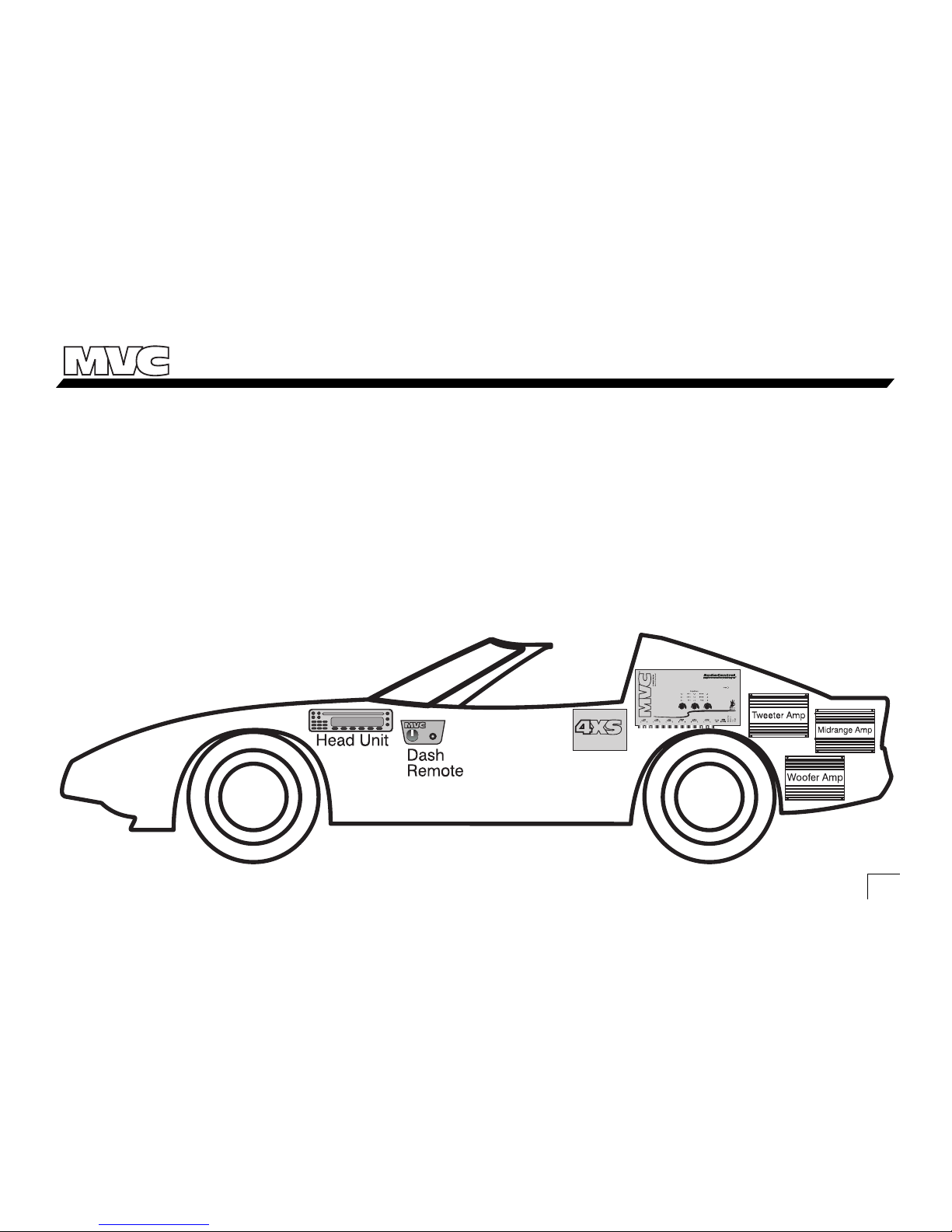
THE AWESOME BENEFITS OF YOUR MVC
How Does The MVC Do Its Thing?
The MVC is designed to go in the rear of the vehicle, by
your amplifiers and processors. However it can be controlled
anywhere inside (or outside) the vehicle by a remote
mounted volume control. By lowering the volume/signal
3
Figure 1- Basic MVC System
level at the rear of the car, rather than the front, you can
squeak all the signal possible from your source unit and run
it to the rear of your car. You are now delivering more signal
to your amplifiers and it is noise free.
Page 6
Owner’s Enjoyment Manual
®
The MVC controls the signal running into the amplifiers.
If you have a “high output voltage” source unit, remember
that if the volume on the source unit is only 1/2 way up, you
are only sending
1
/2 the “high output voltage” to your
amplifiers.
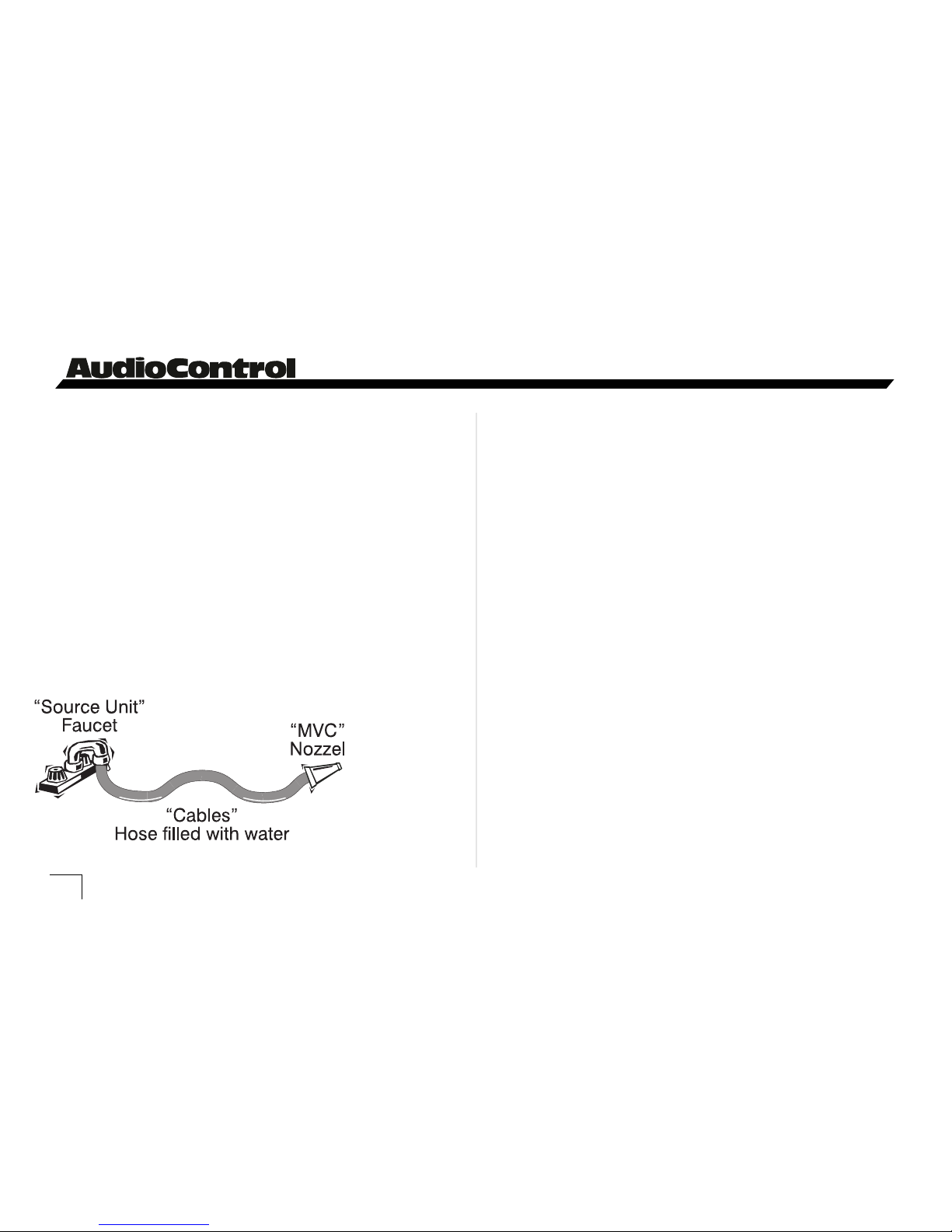
How Do I Tell My Friends About My MVC
And Sound Cool?
A wonderful analogy of this whole process is that of a
faucet, a garden hose, and a nozzle. Your source unit is a
faucet on a sink that is opened up and lets the maximum
amount of pressure flow through the hose, which is your
interconnect cables. The MVC is the nozzle at the end of the
hose that
maintains the
high pressure,
or in this case
high signal
level, and
serves as an
audio signal
valve.
What Is Dynamic Range (and should I care?)
The dynamic range of an audio system is the measurement from when the system is playing its loudest to the part
where it is playing the quietest. If you are into rock’n roll,
then you want those guitar licks to be clean, loud and in
your face. On the other hand if you like jazz or orchestral
music, you will appreciate the clarity and crispness of your
system at lower levels.
Sometimes dynamic range and signal-to-noise are
confused with each other. Quite simply, your audio system’s
dynamic range will never be better than your systems S/N
ratio. Therefore, if you have a noisy system, you are missing
out!
Signal-To-Noise: The Up and Coming Rock Group?
Your system’s signal-to-noise ratio is the measurement
between your audio signal level, which contains music, and
your system’s noise floor, which contains hiss, pops, buzzes,
and whines. If you are listening to your buddies car audio
system and it has all of the above obnoxious sounds...even
when the music is playing, we call that LOW signal-to-noise.
Figure 2- How the MVC works
4
Page 7
Owner’s Enjoyment Manual
Master Volume Control
tm
On the other hand if you have your volume control cranked
up and on quiet songs, you hear almost ZERO background
noise, that is considered a HIGH signal-to-noise level. Most
serious sound-off competitors have high signal-to-noise
ratios (at least the ones that win do).
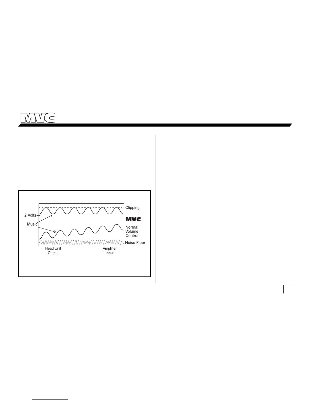
Gain Map
Figure 3 - Using the MVC volume control for optimum signal voltage
versus using just the volume control on the head unit.
With this particular system, the only problem you have
to deal with is the source unit’s volume control. When the
volume control is raised and lowered, the signal voltage is
going to rise and fall also, still minimizing the system’s
potential.
What About High Voltage Head Units?
Many car audio head unit manufacturers are starting to
pull their heads out (a little pun) and realizing that they
should provide head units with higher signal voltage on the
outputs. Not only will this increase a system’s S/N, but it will
also allow you to drive your amplifiers better. Unfortunately,
like any source unit, it has a level or volume control that
raises the signal level up and down. We are back to
square one!
5
Page 8

Owner’s Enjoyment Manual
®
FEATURES AND HIGHLIGHTS
This section is designed to provide for more specific
information on all of the nifty features that are built in to
your MVC. Not only will the knowledge of these features
make you wiser and smarter in the autosound world, you
will be the topic of conversation at soundoff cocktail parties.
Master Volume Control: The MVC will allow you to
run the audio signal at the highest possible level from your
source unit, through the processors, and to the amplifiers.
The MVC will then attenuate the signal level of your car
audio system right before the inputs to your amplifier.
Connectable Inputs and Outputs: If you have a
“serious” car audio system but have more inputs than
outputs, your MVC will be a godsend. Rather than use a
bunch of kludged together cables, the MVC will serve as
your system controller. The incredibly wise engineers at
AudioControl came up with a way in which you can take
two channels of input signal and provide 2, 4, or even 6
channels of output.
Remote Control: The MVC “brains” are designed to be
installed in the rear of the vehicle, while the volume control
knob can be mounted anywhere in the vehicle. (Or outside
the vehicle.) This is ideal if you have a high SPL vehicle.
Output Level Controls: If your system is composed of
more than one amplifier, it is common for one amplifier or
set of speakers to out perform another, causing an unbalanced system. You know the ones, all highs, no lows, must
be...unbalanced. The MVC has output level controls for each
pair of channels. This will allow you to adjust the amount of
signal going to specific amplifiers for a much more balanced
system.
Signal Voltage LED Indicators: The MVC signal
voltage LED indicator tells you precisely how much signal
voltage is present at the outputs of your MVC. This will help
you with matching the output of your MVC with the inputs
of your amplifier.
6
Page 9

Owner’s Enjoyment Manual
Master Volume Control
tm
Linking MVCs: Your MVC can control up to 6 channels
of signal but you also have the ability to add more MVCs if
you have more amplifiers. What is totally cool is that you can
link all of the MVCs together so they operate off the same
dash mounted control.
Turn-On Delay For Amplifiers: Your MVC comes
with an amplifier turn-on delay feature that will allow you to
delay your amplifier turn-on by either 1.5 or 4 seconds. When
running multiple components in your car audio system,
sometimes the amplifiers will turn on faster than your source
units causing an annoying THUMP in your system.
The Most Important Feature Of All: Reliability.
That’s right, your AudioControl MVC comes with a full 5 year
parts and labor warranty when it is installed by an authorized
United States AudioControl dealer. These seasoned pros have
the training and the equipment to take care of the job quickly
and not leave your dashboard looking like Swiss cheese. Keep
in mind that if you or your friends are “good with electronics”
and you choose to install it yourself, the MVC still has a one
year parts and labor warranty.
WARNING:
Perform The Following Task Immediately
Before Going On
To activate your warranty, you need to FILL OUT AND
SEND IN YOUR WARRANTY CARD! Also, save your invoice
or sales slip as proof of purchase. Not only are these necessary for warranty purposes, they are also important if the
unforeseen disappearance of your MVC should happen while
you are socializing at the local espresso and salmon bar.
Insurance companies have very little imagination.
7
Page 10

Owner’s Enjoyment Manual
®
1
2
3
4 5 7 6
8
A GUIDED TOUR OF THE MVC Master Volume Control
8
Page 11

Owner’s Enjoyment Manual
Master Volume Control
tm
9
5 - Linking Output: If your system requires more than
one MVC (more than 3 amplifiers), the linking control will
allow your MVC to pass control signal to another MVC
input. More about this on page 18.
6- Power Connection: This nifty little connector will
allow you to wire up your MVC in the daylight as opposed to
doing it with your head crammed in the trunk. Very cool!
7- Remote Out: The remote output allows your MVC
to delay the turn-on of your amplifiers. You can change the
delay time from 1.5 seconds to 4 seconds by adjusting
jumpers under the chassis top. This will help eliminate any
turn-on thump you get when the source unit turns on slower
than the amplifiers.
8- Made In America: This symbol indicates that your
MVC was lovingly designed and assembled in the USA.
Baseball, hot dogs...you know the rest. Just a reminder that
AudioControl provides a full 1 year parts and labor warranty
on any product we manufacture. However, if your authorized AudioControl autosound dealer installs your MVC,
your warranty is extended a FULL FIVE YEARS!
1- Signal Inputs and Outputs: The MVC can take up
to six channels of input signal and provide up to six channels
of output signal. When a signal is fed into the “Channel 3”
inputs of the MVC it has the ability to send a signal to the
“Channel 3” and “Channel 2” and/or “Channel 1” outputs.
2- PFM Filter: The “Channel 3” inputs utilize a PFM
subsonic filter which will help with speaker control and
amplifier power management. To change the PFM frequency,
you need to remove the top of the chassis and change the
modules. Your local AudioControl dealer generally carries an
assortment of these replacement modules. This is discussed in
detail on page 18.
3- Output Level Adjustments and Indicators: The
MVC has output level adjustments for each pair of channels to
allow for the balancing of your system without having to
adjust your amplifiers gains. The LED indicators display the
amount of signal present at the outputs of your MVC.
4- Remote Input: This input connects via a telephone
cord cable to the level control of your MVC. Should you
connect it to an actual phone, you will definitely get a wrong
number.
A GUIDED TOUR OF THE MVC Master Volume Control
Page 12

Owner’s Enjoyment Manual
®
Figure 5 - Internal Jumper Connections On MVC
WARNING: Failure to disconnect the negative terminal
of your battery prior to the installation of your MVC can
result in a warm tingly feeling.
10
Up to this point everything you have read has served to
educate you on the operation of the MVC. We are sure that
you are chomping at the bit to install your MVC so we
recommend you read the following sections very carefully.
Placement & Mounting of the MVC
Placement: The MVC needs to be installed in the signal
path just prior to your amplifiers inputs. Hence, the closer
the MVC is to your amplifiers (physically not emotionally),
the better. Needless to say, in your efforts to mount the MVC
as close to the amplifiers as possible, be careful drilling holes.
You may put a hole in a gas tank or electrical wiring if you’re
not careful.
Mounting: Once you have selected a permanent
mounting location, position the unit and mark the appropriate mounting holes with a felt-tip pin or scratch awl. After
drilling small pilot hole, secure your MVC with self tapping
screws.
INSTALLING YOUR MVC Master Volume Control
Page 13

Owner’s Enjoyment Manual
Master Volume Control
tm
Electrical Connections
Remote In: Connect a 22 to 18 gauge wire from the
head-unit’s remote turn-on to the “Remote In” connector on
the MVC.
Positive (+12V) Connection: Insert an 18 gauge or
larger wire into the connector labeled “Power” on the nifty
connector of your MVC. Connect it to a good constant
source of 12 volts (we suggest the battery), fused at 1 amp.
Ground Connection: Use the same gauge wire as you
did for the positive connector and run it from the “Ground”
connector on the MVC to the negative terminal of the
battery, a ground bus, or a verified ground location. The
factory head unit ground is not a good ground!
Remote Out: Connect an 18 to 22 gauge wire from the
“Remote Out” on your MVC to the turn-on trigger of your
amplifier. If you wish to change this delay from 1.5 seconds
to 4 seconds, remove the chassis top and move the labeled
jumper.
When the electrical connections are complete, you may
reconnect the negative terminal to your battery.
11
Figure 6 - Front View of MVC
Page 14

Owner’s Enjoyment Manual
®
AUDIO CONNECTION AND
By now you have realized that there are as many ways to
configure the MVC master volume control as there are
speaker companies. Prior to your installation, spend some
quality time sketching out your system configuration. We
have included several diagrams in the next section to give
you some ideas. When installing the MVC, follow the next
steps meticulously:
1. Connect the inputs of your MVC to the outputs of the
last component (source unit, crossover or processor) before
your amplifier. At this time do not connect the MVC
outputs to your amplifiers.
2. Set the input and output level control on all processors,
crossovers, etc. to 0dB. This should equate to the highest level
they can reach without clipping.
3. Turn the control knob on the MVC all the way up.
4. Turn on your system and increase the volume control
on your source unit up approximately 70-80% (or just below
clipping if you know where that is).
5. Play your favorite tape or compact disc that contains
constant, dynamic music. No rap or orchestral music.
Remember you still have NOT connected the inputs to your
amplifiers!
6. With the music playing, (yet you don’t hear anything)
adjust the output level controls until the voltage LEDs on the
“Output Status Indicators” start to flash along with the
music. Take a moment to dance to the beat if you wish.
12
AUDIO CONNECTION AND LEVEL MATCHING
Page 15

Owner’s Enjoyment Manual
Master Volume Control
tm
13
System Diagram - MVC with a 2XS and 2 amplifiers
Page 16
Owner’s Enjoyment Manual
®
14
11. Using either a Real Time Analyzer (blatant plug for
AudioControl products) or just your ears, if there are no other
options, adjust the output levels on your MVC to balance the
sound of your system. You will want an equal amount of
bass, midbass, midrange, and high frequencies. Try not to
increase or “boost” the output controls of the quieter
amplifiers but decrease or “cut” the louder amplifiers.
12. You will have achieved optimum level settings (aka
audio nirvana) for your system when the volume control for
the MVC is maximized and the amplifiers are just starting to
clip. If you have a different experience, see the section on
troubleshooting.
7. Check your amplifiers owner’s manual or on the unit
itself to determine the highest voltage of signal you can send
in to your amplifier. (If you are still dancing from the
previous step, you may now stop!)
8. Adjust the output level controls on your MVC until the
voltage indicator LEDs are flashing at the maximum signal
voltage level your amplifier can handle.
9. Reduce the volume on your MVC dash control, but
don’t touch your source unit. Set the gains on your amplifiers at the highest input voltage setting. In some this means
turning the gain controls counter-clockwise also known as
“turning them down”.
10. Connect the RCAs between the MVC and your
amplifier(s) and raise the signal level, using your MVC, to a
medium level.
AUDIO CONNECTION & LEVEL MATCHING continued
Page 17
Owner’s Enjoyment Manual
Master Volume Control
tm
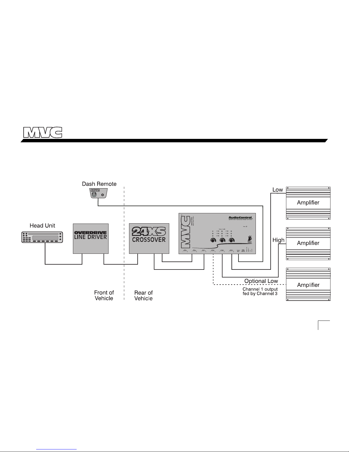
System Diagram - MVC with a 24XS, 2 amplifiers plus additional
subwoofer amplifier
15
Page 18
Owner’s Enjoyment Manual
®
16
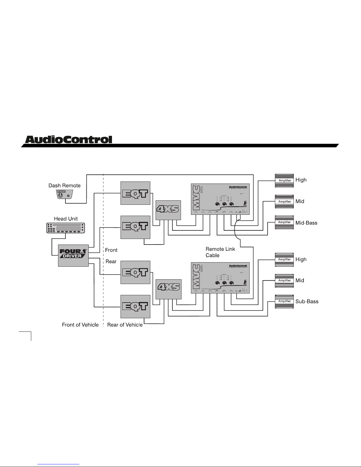
System Diagram - MVC Competition System
Page 19
Owner’s Enjoyment Manual
Master Volume Control
tm
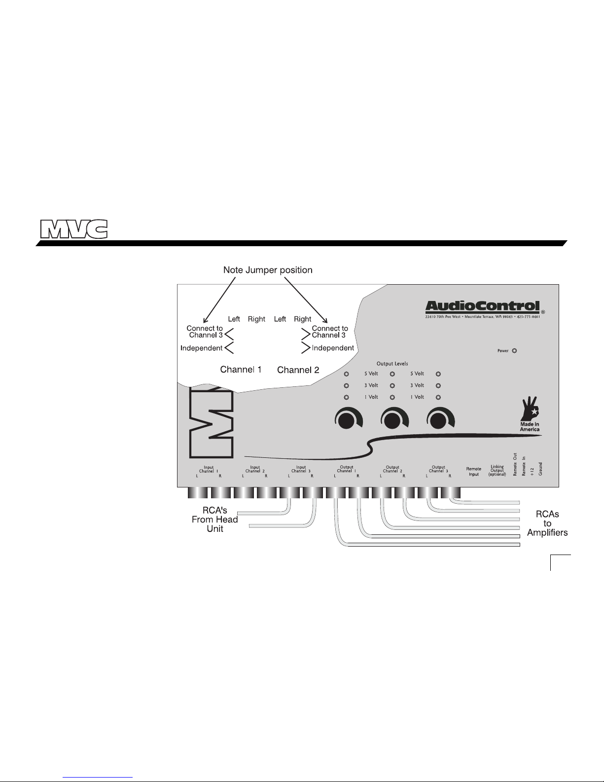
Figure 10 - Connecting 2 channels
of input to 6 channels of output
CONNECTING
INPUTS
If you are running a two
channel system but wish to
connect to more than one
amplifier, you can link the
inputs from “Channel 3”, to
the outputs of “Channel 3”,
“Channel 2” and “Channel
1”. Very cool! To change the
signal configuration, remove
the chassis top and move the
jumpers to the appropriate
labeled configuration. See
figure 10.
17
Page 20
Owner’s Enjoyment Manual
®
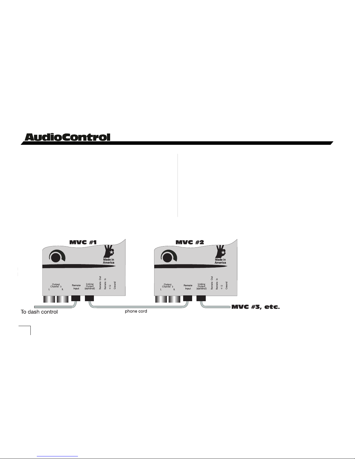
Figure 11 - Linking more than 1 MVC
Linking More Than One MVC
If you find yourself with more amplifier inputs than you
have MVC outputs. . . fear not as we have predicted this
situation. You can connect multiple MVCs together yet have
them all operate using the same control. This is ideal for
competition systems or when you are building a high SPL
system. Connect the Linking Output of MVC #1 with the
Remote Input of MVC #2. Use the dash control connected to
MVC #1 to control the entire system!
18
PFM Module
Many car audio systems truly push the limits of their
subwoofer...without really knowing it. Tuned enclosures
effect the roll-off of many speakers, yet lots of source
materials force the speakers to play lower than expected.
The net result is wasted amplifier power and damaged
speakers. The AudioControl PFM (Programmable Frequency Match) filter is a programmable subsonic filter. It
allows you to only let the speaker play as low as it should
be playing. Because every
system is different, we allow
you to change the PFM roll-off
frequency to whatever you
choose. Just remove the cover
on your MVC and replace the
factory installed PFM module
with one of your choosing.
Page 21

Owner’s Enjoyment Manual
Master Volume Control
tm
TROUBLE SHOOTING
Clipping: If your system “clips” or distorts at medium
volumes, check to make sure your the gain controls on your
amplifiers are at the proper setting or the output level
controls on your MVC may need to be decreased.
Voltage Indicators Don’t Come On: Make sure the
“Power” LED is on. If so then check with your source unit
manufacturer to determine if it produces enough signal
voltage to trigger the LEDs. In many cases, adding the
Overdrive line driver or FOUR.1 in-dash EQ will solve this
problem.
Low Volume: If you find that you are getting low
volume when your MVC is control is maximized, re-adjust
your output levels.
19
Doodle here. . .
Page 22
Owner’s Enjoyment Manual
®
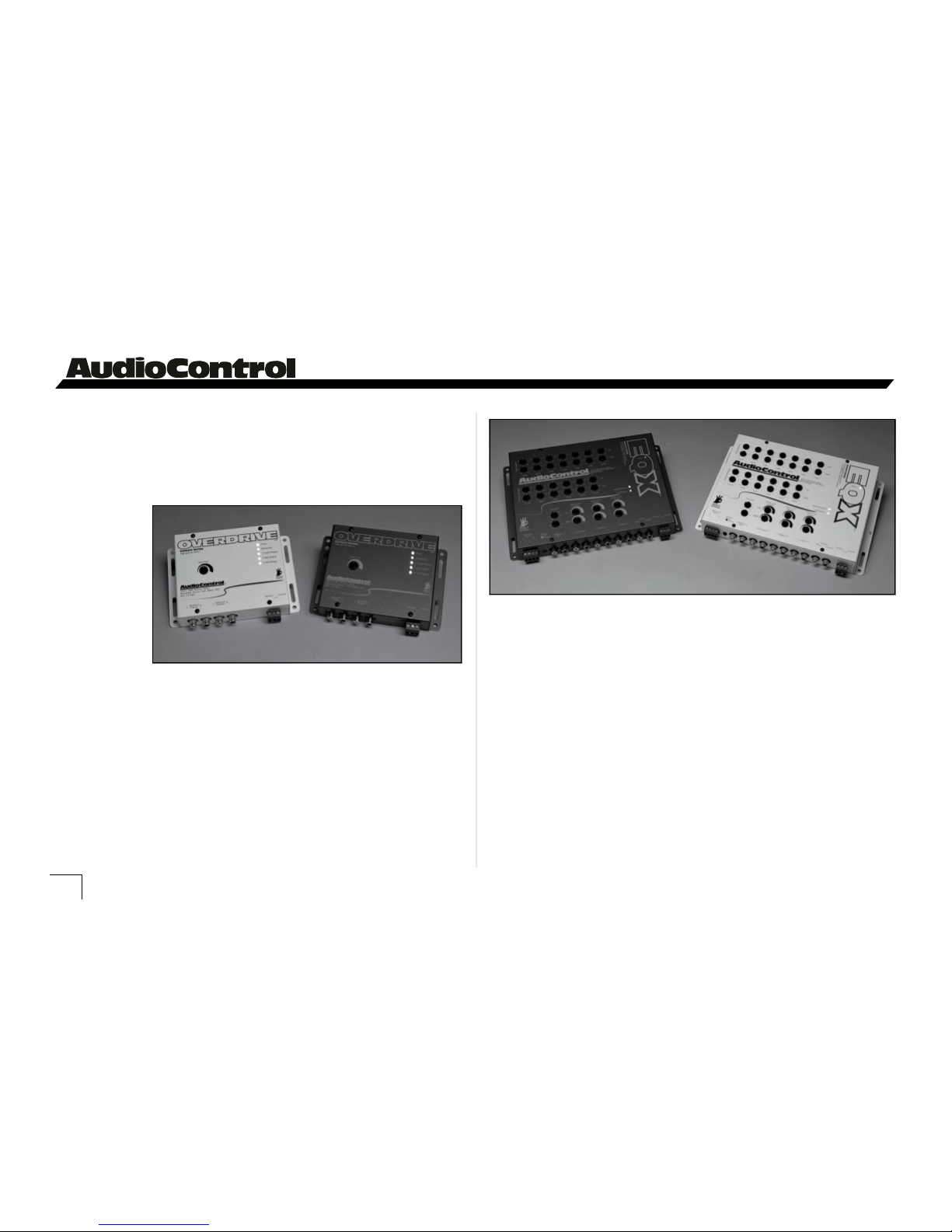
The Overdrive
IF YOU LIKE THE MVC, YOU’LL LOVE...
The Overdrive. If more signal voltage is necessary in your
system, don’t feel alone. Many customers have added The
Overdrive
line driver
and felt like
they had new
amplifiers.
Do you like
great sound,
but you’re
kind of
addicted to
the features of your factory source unit? You know, steering
wheel controls, clean cosmetics, or maybe the backlighting is
just the way you like it? Whatever the case, you are a
candidate for The EQL
tm
.
The EQL is our award winning
dual-bandwidth, trunk mount equalizer, with a bonus! It has
speaker level inputs! Run your factory head unit right into
the EQL and BOOM, instant adapter/equalizer/line driver.
20
Thirteen full octave and 1/2-octave spaced bands help tame
even the most wicked acoustical environment, your car.
Need a crossover and an equalizer? The EQXtm is just the
ticket and will also connect directly to your factory head unit.
The Epicenter
tm
. Our patented (US Patent #4,698,842)
bass restoration component, that puts the “woof” back into
woofer just got better! More Bass Louder! That’s the new
Epicenter. You have to hear it to believe it.
The 3XStm. A 4 channel, 2 way crossover with breathtak-
ingly steep 24dB per octave slopes. If performance is important to you, then you will appreciate the 3XS.
The EQX
Page 23

Owner’s Enjoyment Manual
Master Volume Control
tm
And now a word from the legal department...
THE WARRANTY
People are scared of warranties. Lots of fine print, lots of
noncooperation, months of waiting around. Well, don’t be
scared of this warranty. It’s designed to make you rave about
us to your friends. It’s a warranty that looks out for you and
helps you resist the temptation to have your friend “who’s
good with electronics” try to repair your AudioControl MVC.
So go ahead and read this warranty, then enjoy your new
component for a few days before sending in the warranty
card and comments.
“Conditional” doesn’t mean anything ominous. The
Federal Trade Commission tells all manufacturers to use the
term to indicate that certain conditions have to be met
before they’ll honor the warranty. If you honor these conditions, we will warrant all materials and workmanship on
your MVC for five years from the date you bought it, if
installed by an authorized AudioControl dealer, and will fix
or replace it, at our option, during that time.
Here are the conditions that make this warranty condi-
tional:
1. You have to fill out the warranty card and send it to us
within 15 days after you purchase your MVC.
2. You must keep your sales slip or receipt so you have
proof when and from whom you bought your MVC. We’re
not the only company to require this, so it’s a good habit to
be in with any stereo purchase.
3. Your MVC has to have been originally purchased from
an authorized AudioControl dealer. You do not have to be
the original owner to take advantage of the warranty, but the
date of purchase is still important, so be sure to get a copy of
the sales slip from the original owner.
4. You cannot let anybody who isn’t: (a) the AudioControl
Factory; (b) an authorized service center; or (c) someone
authorized in writing by AudioControl service your MVC. If
anyone other than (a), (b) or (c) messes with your MVC, that
voids the warranty.
21
Page 24

Owner’s Enjoyment Manual
®
5. The warranty is also void if the serial number has been
altered or removed, or if the AudioControl MVC is used
improperly. Now, that sounds like a big loophole, but here is
all we mean by it.
Unwarranted abuse is: (a) physical damage (our mobile
products are not meant to be used as jack stands for your car);
(b) improper connection (we have done the best we can to
protect the inputs, however, 120 volts into the jacks can fry
the innards of the poor beasty); (c) sadistic things.
This is the best mobile product we know how to manufacture, but if you use it for the front bumper of your Baja
bug and get it full of water and dirt, things will go wrong.
Assuming you conform to numbers 1 through 5, and it
isn’t all that hard to do, we get the option of deciding
whether to fix your old unit or replace it with a new one.
Legalese Section
This is the only warranty given by AudioControl. This
warranty gives you specific legal rights, and you may also have
rights that vary from state to state. Promises of how well the
MVC will work are not implied by this warranty. Other than
what we’ve said we’ll do in this warranty, we have no obligation, express or implied. We make no warranty of merchantability or fitness for any particular purpose. Also neither we nor
anyone else who has been involved in the development or
manufacture of the unit will have any liability of any incidental, consequential, special or punitive damages, including but
not limited to any lost profits or damage to other parts of your
system by hooking up to the unit. Whether the claim is one for
breach of warranty, negligence of other tort, or any other kind
of claim. Some states do not allow limitations of consequential
damages.
Failure to send in a properly completed warranty card
negates any service claims.
The warranty included with the unit shall supersede this
plain-text version, if there is any inconsistency between the two.
Failure to send in a properly completed warranty card
negates any service claims.
22
Page 25

Owner’s Enjoyment Manual
Master Volume Control
tm
23
MVC SPECIFICATIONS
All specifications are measured at 14.4 VDC (standard automotive voltage). As technology advances,
AudioControl reserves the right to continuously change our specifications, like our weather.
Maximum input/output level . . . . . . . . . . . . . . . . . . . . . . . . . . . . . . . . . . . . . . . . . . . . . . . . . . . . . . . . . . . . . 10 Vrms
Frequency response . . . . . . . . . . . . . . . . . . . . . . . . . . . . . . . . . . . . . . . . . . . . . . . . . . . . . . . . . . . .10Hz-100kHz;
+1dB
Total harmonic distortion . . . . . . . . . . . . . . . . . . . . . . . . . . . . . . . . . . . . . . . . . . . . . . . . . . . . . . . . . . . . . . . . . . . 0.03%
Signal to Noise ratio . . . . . . . . . . . . . . . . . . . . . . . . . . . . . . . . . . . . . . . . . . . . . . . . . . . . . . . . . . . . . . . . . . . . . . . . . . -110dB
Input Impedance . . . . . . . . . . . . . . . . . . . . . . . . . . . . . . . . . . . . . . . . . . . . . . . . . . . . . . . . . . . . . . . . . . . . . . . . .20 Kohms
Output Impedance . . . . . . . . . . . . . . . . . . . . . . . . . . . . . . . . . . . . . . . . . . . . . . . . . . . . . . . . . . . . . . . . . . . . . . . 150 Ohms
Inputs . . . . . . . . . . . . . . . . . . . . . . . . . . . . . . . . . . . . . . . . . . . . . . . . . . . . . . . . . . . . . . . . . . . . . . . . . . . . . . . . . . . . 6 channels
Outputs . . . . . . . . . . . . . . . . . . . . . . . . . . . . . . . . . . . . . . . . . . . . . . . . . . . . . . . . . . . . . . . . . . . . . . . . . . . . . . . . . . 6 channels
Programmable Frequency Match Filter . . . . . . . . . . . . . . . . . . . . Factory set @ 33 Hz (Programmable)
Output attenuation . . . . . . . . . . . . . . . . . . . . . . . . . . . . . . . . . . . . . . . . . . . . . . . . . . . . . . . . . . . . . . . . . . . . . . . . . . . 24 dB
Power supply . . . . . . . . . . . . . . . . . . . . . . . . . . . . . . . . . . . . . . . . . . . . . . . . . . . . . . . . . . . . . . . High headroom PWM
Power draw . . . . . . . . . . . . . . . . . . . . . . . . . . . . . . . . . . . . . . . . . . . . . . . . . . . . . . . . . . . . . . . . . . . . . . . . . . . . . . . . . . 250mA
Recommended fuse rating . . . . . . . . . . . . . . . . . . . . . . . . . . . . . . . . . . . . . . . . . . . . . . . . . . . . . . . . . . . . . . . . . . . 1 Amp
Size. . . . . . . . . . . . . . . . . . . . . . . . . . . . . . . . . . . . . . . . . . . . . . . . . . . . . . . . . . . . . . . . . . . . . . . 9.75" W x 1.15" H x 5.25" D
Weight . . . . . . . . . . . . . . . . . . . . . . . . . . . . . . . . . . . . . . . . . . . . . . . . . . . . . . . . . . . . . . . . . . . . . . . . . . . . . . . . . . . . 2 lbs, 3 oz.
Ground Isolation jumpers . . . . . . . . . . . . . . . . . . . . . . . . . . . . . . . . . . . . . . . . . . . . . . . . . . . . . . . . . . . . . . . . . . . . . . .Yes
Remote out delay options . . . . . . . . . . . . . . . . . . . . . . . . . . . . . . . . . . . . . . . . . . . . . . . . . . . . . . . . . 1.5 & 4 seconds
Country of origin . . . . . . . . . . . . . . . . . . . . . . . . . . . . . . . . . . . . . . . . . . . . . . . . . . . . . . . . . . . . . . . . . . . . . . . . . . . . .U.S.A.
Page 26

Owner’s Enjoyment Manual
®
24
MVC BLOCK DIAGRAM
Page 27

Owner’s Enjoyment Manual
Master Volume Control
tm
25
This page was also intentionally left almost blank.
Page 28

This manual was written while stomping puddles till our overshoes were filled and our moms made us a hot bowl of chicken
soup on a typically rainy day in the Pacific Northwest.
Electronic Engineering & Manufacturing, Inc
®
P/N 9130320
© 1998, AudioControl. All rights reserved.
22410 70th Avenue West • Mountlake Terrace, WA 98043
Phone 425-775-8461 • Fax 425-778-3166
www.audiocontrol.com
®
making good stereo sound better
®
 Loading...