

Page 1
Home Theater
S Y S T E M
High Performance Pre-Amplifier
Surround Processor
tm
with Active Balanced Technology
Owners Enjoyment Manual
For those who consider
perfection possible
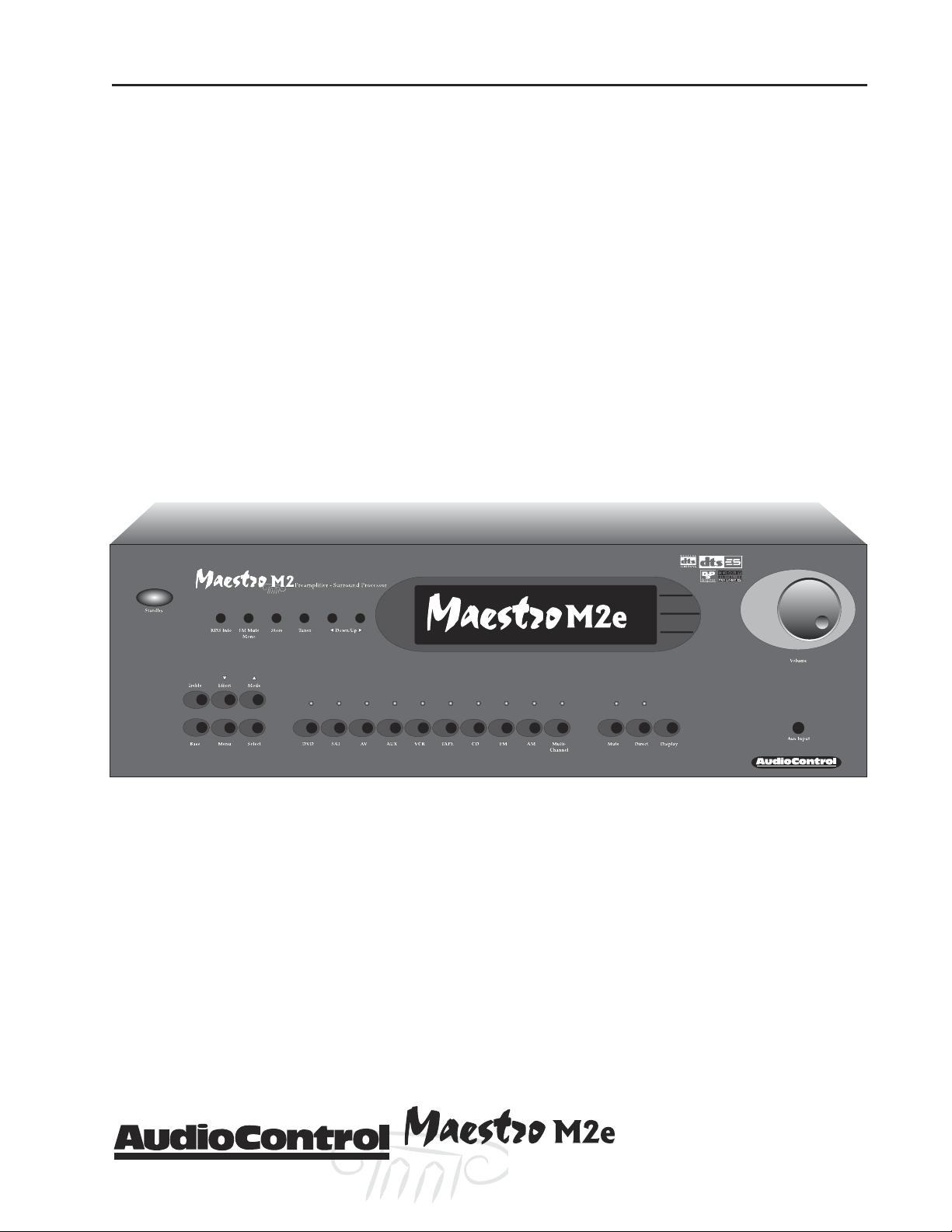
22410 70th Avenue West • Mountlake Terrace, WA 98043 USA
Phone 425-775-8461 • Fax 425-778-3166
www.audiocontrol.com
®
®
©2006. All Rights Reserved
Rev 1.1
Page 2

Page 3
High Performance Pre-Amplifier
Surround Processor
with Active Balanced Technology
Owners Enjoyment Manual
tm
For those who consider
perfection possible
22410 70th Avenue West • Mountlake Terrace, WA 98043 USA
Phone 425-775-8461 • Fax 425-778-3166
www.audiocontrol.com
©2006. All Rights Reserved
Rev 1.1
®
®
Page 4

4
This page was intentionally left blank. Please enjoy it!
tm
®
Phone 425-775-8461 • Fax 425-778-3166
Page 5

Table of Contents
Introduction . . . . . . . . . . . . . . . . . . . . . . . . . . . . . . . . . . . . . . . . . . . . . . . . . .7
Key Features and Highlights . . . . . . . . . . . . . . . . . . . . . . . . . . . . . . . . . . .8
Guided Tour of the Masestro M2e
Front Panel Features . . . . . . . . . . . . . . . . . . . . . . . . . . . . . . . . . . .10
Rear Panel Features . . . . . . . . . . . . . . . . . . . . . . . . . . . . . . . . . . . .12
Set-Up & Configuration
Unit Placement . . . . . . . . . . . . . . . . . . . . . . . . . . . . . . . . . . . . . .15
Speaker Considerations and Placement . . . . . . . . . . . . . . . . . . . .15
Power Wiring . . . . . . . . . . . . . . . . . . . . . . . . . . . . . . . . . . . . . . . .17
Audio Connections . . . . . . . . . . . . . . . . . . . . . . . . . . . . . . . . . . . .17
System Diagram . . . . . . . . . . . . . . . . . . . . . . . . . . . . . . . . . . . . . .18
Video Connections . . . . . . . . . . . . . . . . . . . . . . . . . . . . . . . . . . . .19
IR Controls . . . . . . . . . . . . . . . . . . . . . . . . . . . . . . . . . . . . . . . . . .20
12V Trigger Connections . . . . . . . . . . . . . . . . . . . . . . . . . . . . . . .21
Zone 2 . . . . . . . . . . . . . . . . . . . . . . . . . . . . . . . . . . . . . . . . . . .21
Main User Menus
Navigating the Setup Menu . . . . . . . . . . . . . . . . . . . . . . . . . . . . .23
Inputs and Volume . . . . . . . . . . . . . . . . . . . . . . . . . . . . . . . . . . .23
Audio Settings . . . . . . . . . . . . . . . . . . . . . . . . . . . . . . . . . . . . . . .23
Zone 2 Settings . . . . . . . . . . . . . . . . . . . . . . . . . . . . . . . . . . . . . .24
Advanced Setup Menus
General Settings . . . . . . . . . . . . . . . . . . . . . . . . . . . . . . . . . . . . . .25
Speaker Sizes . . . . . . . . . . . . . . . . . . . . . . . . . . . . . . . . . . . . . . . .26
Subwoofer Settings . . . . . . . . . . . . . . . . . . . . . . . . . . . . . . . . . . .27
Delay Settings . . . . . . . . . . . . . . . . . . . . . . . . . . . . . . . . . . . . . . . .28
Level Settings . . . . . . . . . . . . . . . . . . . . . . . . . . . . . . . . . . . . . . . .28
EX Settings . . . . . . . . . . . . . . . . . . . . . . . . . . . . . . . . . . . . . . . . . .29
Speaker Eq Settings . . . . . . . . . . . . . . . . . . . . . . . . . . . . . . . . . . .30
Video Settings . . . . . . . . . . . . . . . . . . . . . . . . . . . . . . . . . . . . . . . .30
Digital Settings . . . . . . . . . . . . . . . . . . . . . . . . . . . . . . . . . . . . . . .30
Zone 2 Settings . . . . . . . . . . . . . . . . . . . . . . . . . . . . . . . . . . . . . .31
Input Trim . . . . . . . . . . . . . . . . . . . . . . . . . . . . . . . . . . . . . . . . . .31
HDMI Settings . . . . . . . . . . . . . . . . . . . . . . . . . . . . . . . . . . . . . . .32
®
Phone 425-775-8461 • Fax 425-778-3166
tm
5
Page 6

Table of Contents
Operating The Maestro M2e
Surround Modes
Automation Integration
Troubleshooting
Power . . . . . . . . . . . . . . . . . . . . . . . . . . . . . . . . . . . . . . . . . . . . . .33
Menu . . . . . . . . . . . . . . . . . . . . . . . . . . . . . . . . . . . . . . . . . . . . . .34
Source Selection . . . . . . . . . . . . . . . . . . . . . . . . . . . . . . . . . . . . . .34
Stereo Direct . . . . . . . . . . . . . . . . . . . . . . . . . . . . . . . . . . . . . . . . .35
Display Brightness . . . . . . . . . . . . . . . . . . . . . . . . . . . . . . . . . . . .36
Selecting Surround Modes . . . . . . . . . . . . . . . . . . . . . . . . . . . . . .39
RS-232 Serial Control Protocol Commands . . . . . . . . . . . . . . . . .41
Protocol Structure . . . . . . . . . . . . . . . . . . . . . . . . . . . . . . . . . . . .42
Command Structure and Parameters . . . . . . . . . . . . . . . . . . . . .45
IR Remote Control Codes . . . . . . . . . . . . . . . . . . . . . . . . . . . . . . .49
General . . . . . . . . . . . . . . . . . . . . . . . . . . . . . . . . . . . . . . . . . . . . .51
Video . . . . . . . . . . . . . . . . . . . . . . . . . . . . . . . . . . . . . . . . . . . . . .51
Audio . . . . . . . . . . . . . . . . . . . . . . . . . . . . . . . . . . . . . . . . . . . . . .52
Appendix . . . . . . . . . . . . . . . . . . . . . . . . . . . . . . . . . . . . . . . . . . . . . . . . . . . .55
Warranty . . . . . . . . . . . . . . . . . . . . . . . . . . . . . . . . . . . . . . . . . . . . . . . . . . . .58
Specifications . . . . . . . . . . . . . . . . . . . . . . . . . . . . . . . . . . . . . . . . . . . . . . .61
6
tm
®
Phone 425-775-8461 • Fax 425-778-3166
Page 7
Congratulations
Great attention to system design, installation, and calibration makes
the difference between an average multiplex theatre and a great movie
palace. For your own personal home theater experience, the choice of
components and attention to detail is just as critical as if you were designing a professional installation. For that reason AudioControl created
the Perfection Theater components to allow enthusiasts to experience a
performance theater in their own home.
AudioControl’s passion for high quality, meticulous attention to detail
and pro sound heritage shows itself in the dozens of awards we have
won for our designs, products and service. This manual is designed to
help you get the most from your Maestro M2e pre-amp processor. Even
though you’re dying to plug it in and start pushing buttons, please take
a little time to glance over this users guide and learn about the Maestro
M2e theater surround processor. Any component that does as much as
the Maestro M2e does, deserves all the explanation it can get.
Introduction
Most Important Instruction of All
Make certain the warranty card is filled out and mailed back to us. Also,
record the serial number and put your sales receipt or invoice in a safe
place. This is very important in the unlikely event that the Maestro
M2e gets a sudden illness, or for proof of ownership if somebody takes
a fancy to your theater system in the middle of the night. Insurance
companies have no imagination when it comes to components like the
Maestro M2e being part of the theater system. This concludes the nagging section of this manual.
®
Phone 425-775-8461 • Fax 425-778-3166
tm
7
Page 8

Key Features
Key Features Of the Maestro M2e
Multiple Surround Sound Formats
A powerful 32 bit DSP processor enables the Maestro M2e to
decode all current discrete surround digital formats available for 5.1, 6.1 and 7.1. In addition your Maestro M2e has
the capabilities to process two channel signals using Dolby
Pro Logic II, Pro Logic IIx and DTS Neo to provide multichannel output. The flash memory of your Maestro M2e
will allows it to be upgraded in the future when new formats become available.
Balanced Outputs
The Maestro M2e offers balanced XLR outputs for superior
signal to noise performance when interfacing with amplifiers with balanced inputs, like the AudioControl Pantages,
Avalon, or Savoy.
High Definition Video Inputs and Switching
Great sound is important, but you also need a great picture
to complete your performance home theater. The video
routing and switching in the Maestro M2e has it’s roots in
the broadcast studio. With high video bandwidth, you will
see even the finest details from the video sources even with
demanding 1080 and current progressive scan HDTV signals. In addition, the Maestro M2e switches high end digital video formats like HDMI for easy interface with todays
digital projection devices
8
AM/FM Tuner With RDS Support
The radio tuner in your Maestro M2e can receive both AM
and FM signals. In addition, the RDS (Radio Data System)
feature allows selected FM stations to display their respective names, song titles and even artists on the display of the
Maestro M2e.
Extensive Automation Integration
A touch screen or automation system is what really pulls a
high-end home theater together. It puts the full power of
the system at your fingertips. The RS-232 serial port and infrared remote control inputs feature an extensive command
library to control all aspects of the Maestro M2e. You have
the power.
tm
®
Phone 425-775-8461 • Fax 425-778-3166
Page 9
BVR-25
Balanced Video Receiver
Key Features
Active Balanced Outputs
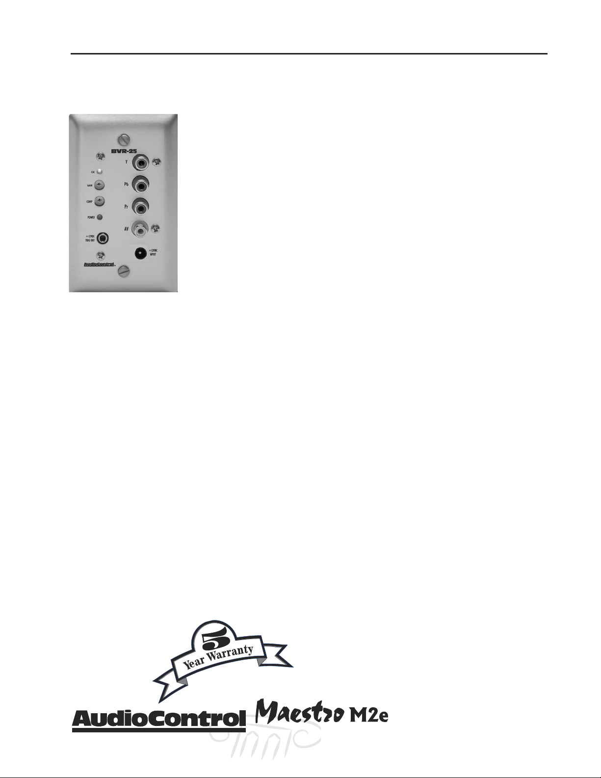
The Maestro M2e is the worlds first theater processor
equipped with an Active Balanced Output which allows it
to output a component video signal via an RJ-45 connector onto standard Category-5 wiring and extend it up to
1000’. The signal is also “balanced” which is a method used
in professional video and audio to reject noise, hum, and
distortion that can sometimes get introduced into signal
paths. An optional (sold separately) AudioControl BVR-25 is
used to receive this balanced signal and convert it back to a
standard component video signal. This is then connected
to your projector, monitor or other video display device.
Because the Maestro M2e was designed with high performance video in mind, the Active Balanced Output on the
Maestro M2e can accommodate high-resolution signals of
480, 720, and 1080!
Second Zone Outputs
Do you want to enjoy your home theater system in the
bedroom also? The Second Zone output of the Maestro enables you to independently control the source selection and
volume to a room outside of the home theater.
AudioControl PerfectionTheater System
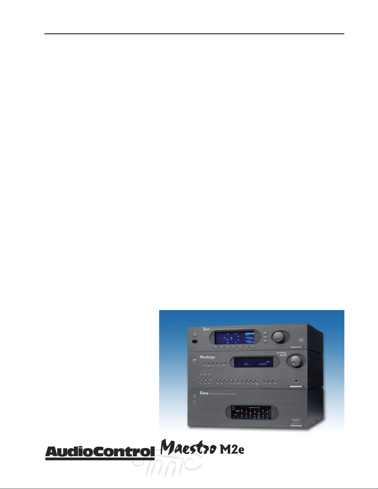
The Maestro M2e is part of the AudioControl Perfection
Theater System. Also included in this system are the Diva
Digital Room Correction Processor combined with the
Avalon, Pantages, or Savoy high definition amplifiers. To
maximize the performance of your Perfection Theater system, we also highly recommend that you have your audio
system calibrated by a factory trained technician using
AudioControl analysis equipment. Together these components ensure superior audio and video performance from
your Prefection Home Theater system.
Award-Winning Quality
The Maestro M2e, like all AudioControl Perfection Theater
components, is backed with a comprehensive five-year
parts and labor warranty. This comes from a company
that has been designing and manufacturing perfor-
mance audio components since 1977.
®
Phone 425-775-8461 • Fax 425-778-3166
tm
9
Page 10
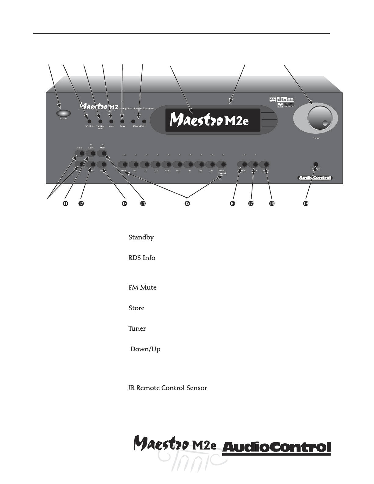
Guided Tour of the Masestro M2e
Front Panel Features
Standby – The switch serves to “wake up” your Maestro M2e, provided the main power switch, located on the rear panel, is turned on.
RDS Info – Displays the RDS (Radio Data System) text information (ie.
song name, artist, etc) provided the radio station selected is transmitting it.
FM Mute – Engages auto-muting circuit which mutes weak FM radio
signals.
Store – Allows you to store your radio presets plus a good place to
buy groceries.
Tuner – Allows you toggle between the two tuning modes (Tune or
Preset).
Down/Up – Pressing these buttons allows you to scroll up and down
through various stations. In the “Preset” mode these buttons scroll
through the 30 FM stations or 10 AM stations stored in the preset
memories of your Maestro M2e.
IR Remote Control Sensor - Behind this display is the infrared sen-
sor remote control. If the Maestro M2e is located in a system where this
window is not line-of-sight with the main listening seat; a rear panel
jack enables use of an outboard IR sensor.
10
tm
®
Phone 425-775-8461 • Fax 425-778-3166
Page 11
Guided Tour of the Masestro M2e
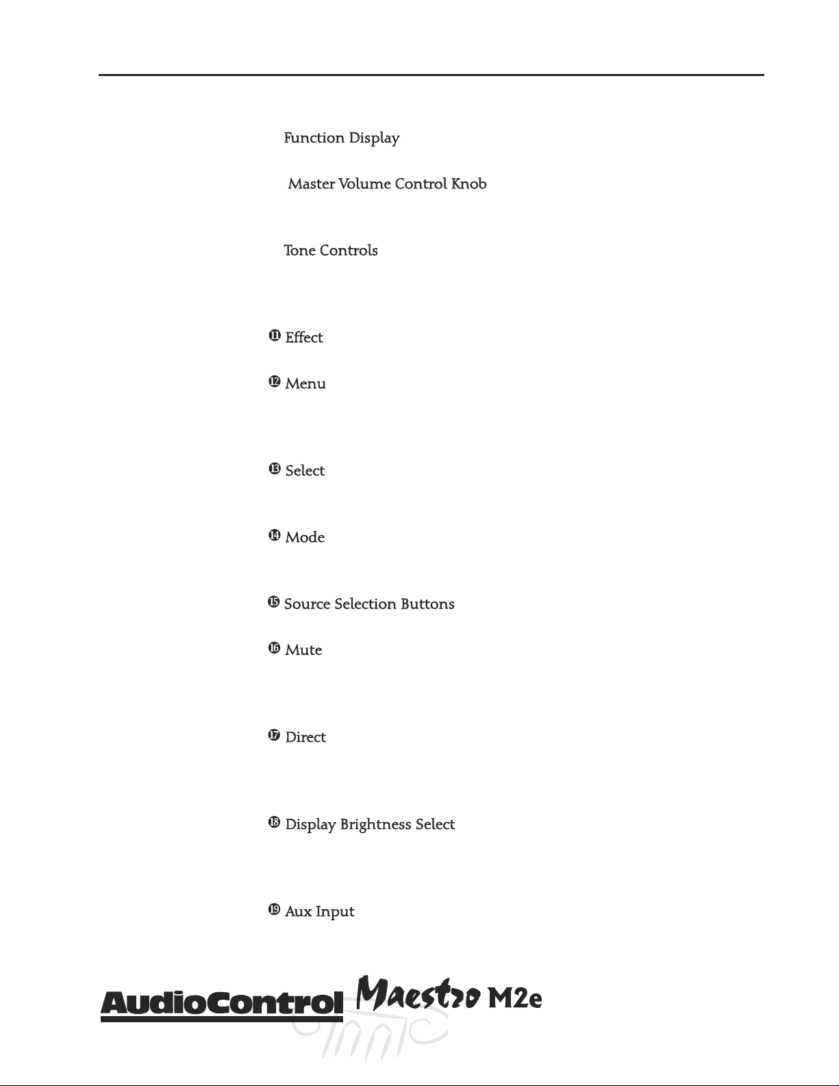
Function Display - With the easy to follow menus, it is simple to operate and configure the Maestro M2e.
Master Volume Control Knob - In normal use, this knob is the volume control. When in the setup menus, turn this knob to select menus
and options.
Tone Controls – By selecting Bass or Treble you can then use the “Mas-
ter Volume” knob on your Maestro M2e to apply basic tone adjustments.
For superior audio calibration adjustment we highly recommend you
consider the AudioControl Diva, Digital Room Correction Processor.
Effect - These buttons allow the user to control the stereo audio sur-
round modes or DSP effects for the various source units.
Menu – Tapping this button will allow you to access the Main Menu
functions of the Maestro M2e. If you have the courage to push and hold
this button for 2 seconds, it will allow you access to the Advanced Menu
functions.
Select – Coincidentally enough, this button allows you to “Select”
various modes or menu screens depending upon which function you
are in.
Mode – When you are using source material containing Dolby Digital
or DTS material, this button lets you cycle through the various surround
modes available for each.
Source Selection Buttons - Simple enough, just press a button to
choose what you want to watch or listen to.
Mute - Need to answer the phone, but still keep an eye on the TV?
Just press the Mute button to turn off the sound. Press it again and the
audio gracefully ramps back up to where you were so rudely interrupted.
Direct - For a two-channel analog input, this button defeats all digital
signal processing and directs the two-channel analog input from the
selected source to the front outputs. Use this button when you want to
do some serious quality two-channel listening.
Display Brightness Select - This button toggles the display between
two brightness levels or completely turns the display off. This is nice to
get rid of distractions while you’re watching a good movie and the
Maestro M2e is in your sight line.
Aux Input – Into this conveniently located jack, plug an exterenal audio device like an MP-3 or even an iPod.
®
Phone 425-775-8461 • Fax 425-778-3166
tm
11
Page 12
Guided Tour of the Masestro M2e
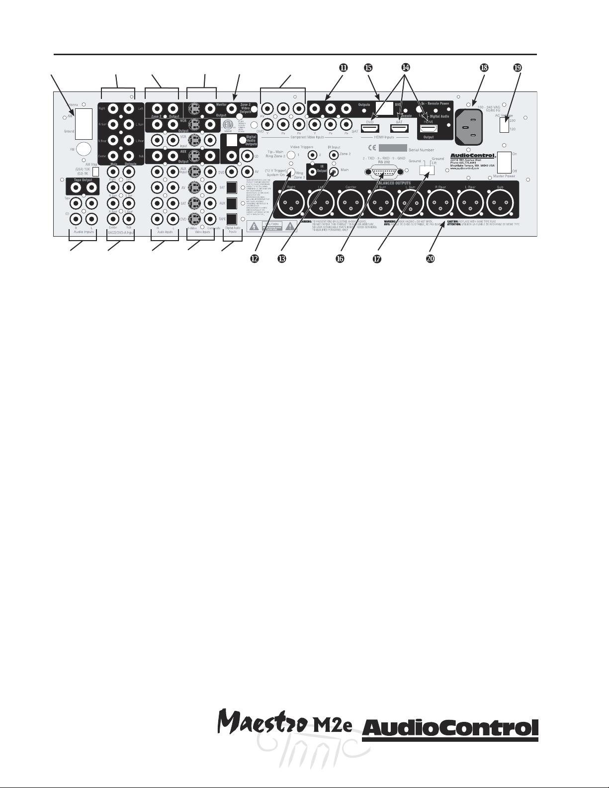
Rear Panel Features
ANTENNA CONNECTIONS – These inputs should be connected to the AM and FM
antennas that are supplied with your Maestro M2e. For optimum reception you
may want to consider a roof mounted external antenna.
STEREO ANALOG AUDIO INPUTS AND OUTPUTS - Connect the appropriate two chan-
nel stereo outputs and inputs from your source units here.
MAIN AMPLIFIER OUTPUTS – These unbalanced RCA outputs feed the main theater
power amplifier(s). (Our customers tell us that our Savoy 7-channel amplifier is awesome. )
MULTI-CHANNEL DVD-A/SACD INPUT - Newer multi-channel audiophile record-
ings give you superb music audio quality in full surround. These players feature a
surround decoder built into them. The Multi-channel inputs on the Maestro M2e
bypass all digital circuitry and connect the player to the amplifiers with only a volume control in the path.
ZONE 2 AUDIO OUTPUT - The second zone outputs enables listening to a source
independently of the main theater system.
MAIN VIDEO OUTPUTS - Connect these Composite and S-Video outputs to your
system’s main video display or projector.
ZONE 2 VIDEO OUTPUT - This is the Composite output for Zone 2. You must con-
nect the Composite video input from each source unit to your Maestro M2e to make
them available for this second zone output.
COMPOSITE AND S-VIDEO CONNECTIONS - These are for the video inputs and out-
puts from your source units. If you are using the second zone video outputs, you
should ALWAYS connect a Composite video input from each source, even if you are
using a higher quality S-Video or Component signal for the main theater. Since these
inputs are assignable you can rearrange the inputs if your CD player has a video output and your tape deck doesn’t.
DIGITAL AUDIO CONNECTIONS - The Maestro M2e features assignable Coaxial and
Optical digital audio inputs and outputs. Don’t worry if your satellite has a Coaxial
digital output but the SAT connection on the back of the Maestro M2e is Optical as
you can reassign the connection.
12
tm
®
Phone 425-775-8461 • Fax 425-778-3166
Page 13
Guided Tour of the Masestro M2e
COMPONENT VIDEO INPUTS - Component video is one of the highest quality for-
mats available. Use it whenever possible.
COMPONENT VIDEO OUTPUT – Connect these high quality video outputs to your
main video display device (ie. Projector, CRT, LCD, etc.) You will be pleased to know
that they will convert the Composite and S-video signals to the Component outputs
of your Maestro M2e. See page 20 for more details.
12 VOLT TRIGGER OUTPUTS - These three outputs provide a +12 volt signal to
control the power amplifiers, source units, video projector, screens and curtains in
the theater. The Main Trigger output is active whenever the Maestro is turned on;
the Video Trigger 2 is active whenever a video source is selected.
IR REMOTE CONTROL CONNECTIONS - These jacks enable use of external IR sensors
and emitters for installations where it is not desireable to use the front panel IR
sensor.
HDMI INPUTS & OUTPUTS – These inputs allow the Maestro M2e to accept digital
video signals from source units equipped with HDMI (High Definition Multimedia
Interface) outputs. The Maestro M2e outputs digital signals via this HDMI output to
a projection device with an HDMI input.
ACTIVE BALANCED OUTPUTS – This conveniently located RJ-45 connector outputs
component video signals PLUS digital audio OR remote power that then runs to an
optional AudioControl BVR-25 balanced line receiver. The switch next to the LED
allows you to select between digital audio or remote power. Hint - Bright red LED
means Remote Power. These outputs run in parallel to the Maestro M2e’s standard
component outputs so you will want to make sure that these component outputs
(YUV) are activated in the General Settings menu (see page 25).
RS-232 SERIAL PORT - This connection is used to interface the Maestro with an
external touch-screen or other automation system. It is also used when updating
the internal Maestro M2e firmware programming.
GROUND LIFT SWITCH - In complex home theater systems, ground loops can be a
painful fact of life. This button isolates the signal ground connections on the Maestro M2e from the AC Power ground. For safety reasons, the chassis remains earth
grounded at all times.
MAIN POWER CONNECTION - All good AC power flows in here.
MAIN POWER SWITCH – Think of this as the vacation switch. You should only need
to turn off your Maestro M2e with this button when the system will not be used for
some time. Normally this button is left on and the Maestro M2e is “woken up” via
the “Standby” switch on the front panel, via the optional remote control or through
an automation system. When this switch is turned off, you cannot turn the Maestro
M2e on of off via any other method.
BALANCED AUDIO OUTPUTS – These outputs send signals to amplifiers with bal-
anced XLR type inputs. This type of configuration yields maximum noise rejection
from the airborne interference and is recommended for applications where you are
sending audio signals over a long distance.
®
Phone 425-775-8461 • Fax 425-778-3166
tm
13
Page 14

Guided Tour of the Masestro M2
14
tm
®
Phone 425-775-8461 • Fax 425-778-3166
Page 15
Set-Up & Configuration
Set-Up & Configuration
Unit Placement
The Maestro M2e can be placed almost anywhere in your
audio equipment stack as it only generates a small amount
of heat during operation. It is good practice to ensure that
the equipment location is properly ventilated and to make
certain not to block the ventilation slots on any other
component. Avoid placing Maestro M2e directly over large
power amplifiers. Unless they are made by AudioControl,
some amplifiers can get pretty hot and have big power
transformers that can induce hum into other audio components like Maestro M2e. Make certain that there is an
unobstructed line-of-sight between the location where the
remote controller sits and the Maestro M2e front panel.
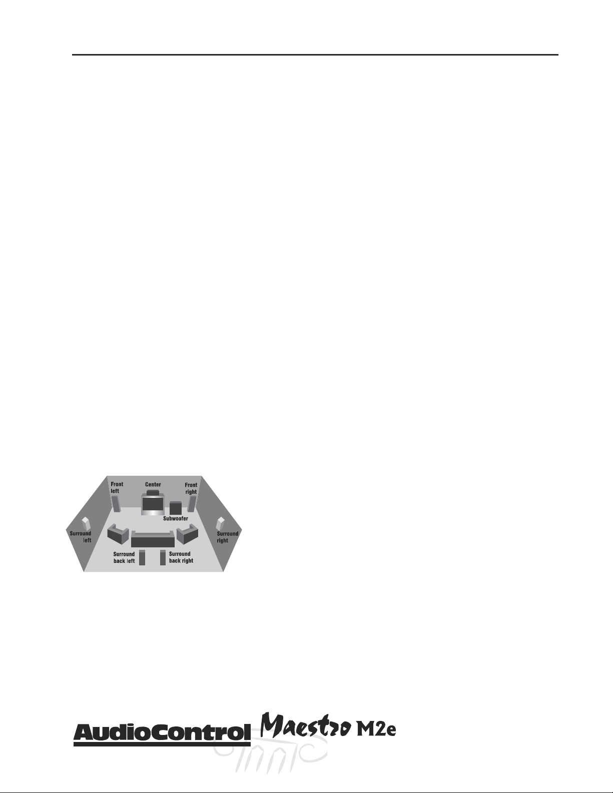
Speaker Considerations and Placement
Choosing the right speakers and putting them in the correct positions is crucial to getting the most out of a home
theater system. For the full THX surround EX playback
experience, we recommend two speakers placed behind
you. Once you have decided on the speakers you are using,
make certain the Maestro M2e is configured to match your
speakers.
Front LCR (Left, Center, Right) Speakers
To present the most realistic soundstage, all three of the
front speakers must be tonally balanced. Ideally, these
speakers should be identical models. This ensures that the
sound doesn’t change as it pans across the screen. Place
the speakers at the seated ear level. Whenever possible, the
three front speakers should also be placed at the same horizontal level for best imaging.
®
Phone 425-775-8461 • Fax 425-778-3166
tm
15
Page 16
Set-Up & Configuration
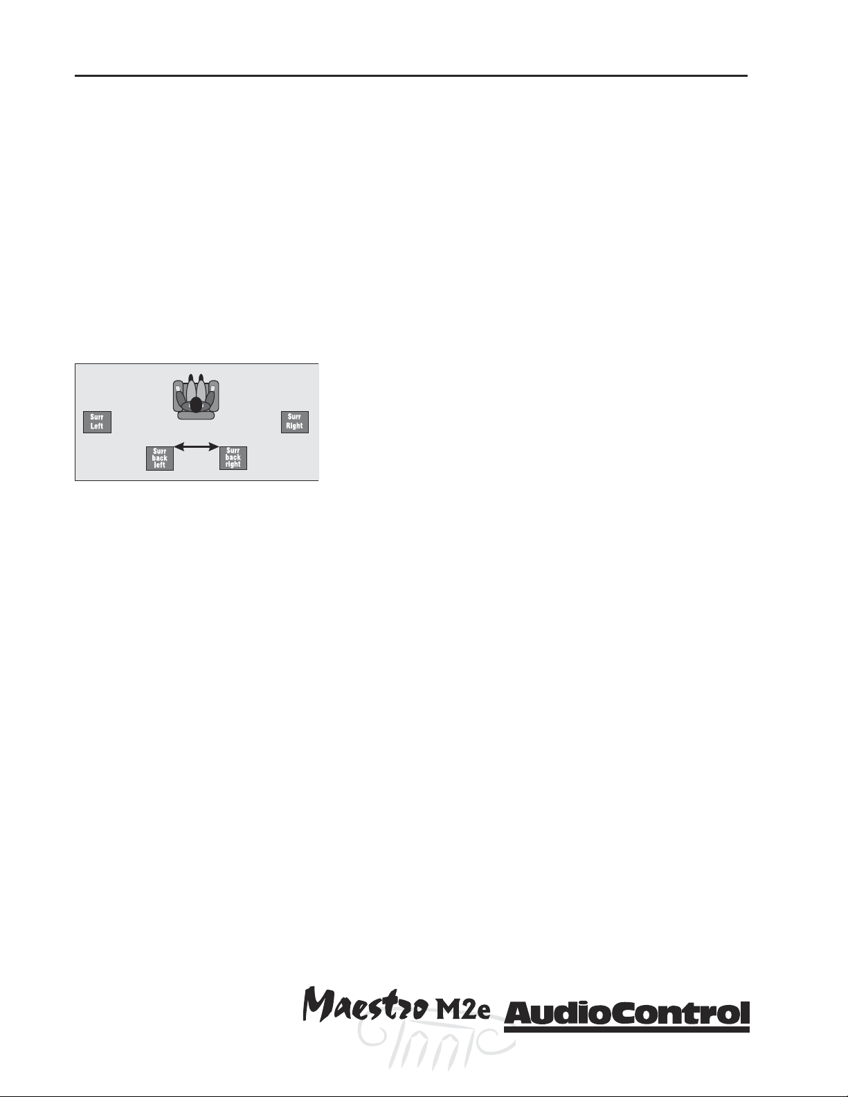
Side Surround Speakers
Rear (Back) Surround Speakers
The surround speakers provide the reverberant, or ambient, sound effects in a multi-channel theater audio system.
These speakers should be placed on the side walls approximately 36” above the seated ear height of the listeners.
If you are using surround speakers which have a dipole
sound pattern they should be mounted in-line with the
main seating position. If the surrounds are direct radiator,
they should be just behind the main listening seat.
Some software provides extra channels that are used in 7.1
mode systems to provide extra depth in the soundfield.
Place these speakers approximately 36” above the seated ear
height of the listeners. Additionally, they should be mounted close together (less than 12” apart) on the rear wall of
the theater facing the screen. If you must place the speakers
further apart, make certain to change the Advanced Speaker
Array setting in the set up menus.
Subwoofer
The subwoofer is a large speaker that provides the bottom
end “kick” in the system. Depending on the size of your listening space, you may require more than one subwoofer to
get the bass volume levels that you desire. Make certain you
remember to include the size of all spaces that are open to
the theater in determining harmony subwoofers you need.
Connection Tips
Even if you’re an electronics veteran, this part may seem
repetitive, but some things can never be repeated too many
times.
• Turn off all components before making any connections.
• When making connections, make sure that “left goes to
left” and “right goes to right.” The obvious and time-honored way to assure this is to assign RED plugs to Right and
WHITE/GREY/BLACK plugs to the left. Yellow is usually used
for video cables or digital audio connections.
16
tm
®
Phone 425-775-8461 • Fax 425-778-3166
Page 17

• Wherever possible, keep power cords away from signal
cables (i.e., inputs from disk players, VCRs, etc.) to prevent
induced hum. Bundle all power cords down one side of
your equipment cabinet and all the signal cables down the
other.
• Use high quality interconnect cables. We’re not going to
get into the debate about whether $100 per meter interconnects improve the sound and picture quality of your
system. We do know from experience however that really,
REALLY cheap connections can cause problems.
• Don’t stand in a bucket of water when working with electricity.
Power Wiring
Like many of today’s intelligent home electronics, the Maestro M2e should be plugged into an unswitched AC outlet
so that it always has power. This allows the RS-232 and remote control features to work even when the Maestro M2e
is in standby. We always recommend the use a high quality
surge protection device to keep all of your electronics safe
from the evils of spikes on power systems.
Set-Up & Configuration
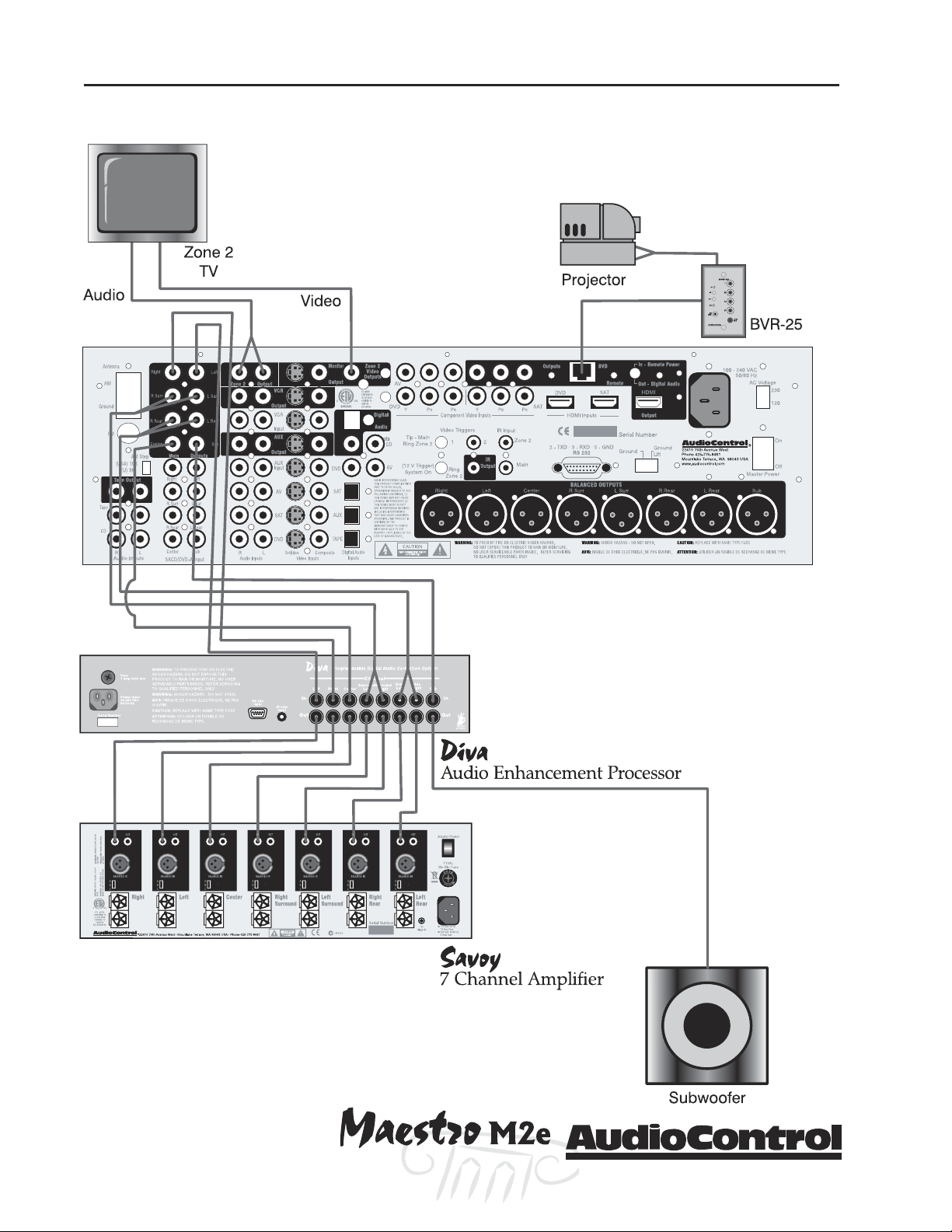
Audio Connections
Most of the sources will have two audio connections to the
Maestro M2e; the 2 channel analog audio and the multichannel digital audio. When given the option, you should
connect both types of audio signals to the Maestro M2e.
This will provide the digital audio signal necessary for highquality digital surround sound along with the analog audio
for tape recording and the second zone audio output.
Don’t worry if your satellite receiver has a coaxial digital
output and the Maestro M2e SAT input is optical. Refer
to the advanced configuration section on page 30 of this
manual for more information regarding assigning a digital
input to the optical or coaxial connection.
®
Phone 425-775-8461 • Fax 425-778-3166
tm
17
Page 18
Set-Up & Configuration
Maestro M2e
tm
18
tm
®
Phone 425-775-8461 • Fax 425-778-3166
Page 19
Types of video connections
Set-Up & Configuration
Multi-Channel Analog Audio
Audiophile surround recording formats such as SACD and
DVD-A decode the multi-channel signals directly within the
player. The Maestro M2e features an 8 channel direct analog input for these sources. These inputs bypass the digital
circuitry in the Maestro M2e and are routed directly to the
Main Amplifier outputs via an independent volume control
circuit. This ensures the highest possible audio quality for
this input.
Video Connections
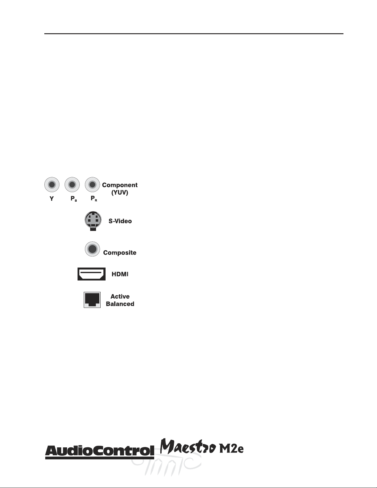
Choosing your video
There are four video signal connection formats ranging
from Composite (Good), S-Video (Better), HDMI digital
video, Active Balanced and Component (Best). Depending
on the particular source unit, you may have the option of
more than one of these video connections. Always choose
the highest quality video output available on your sources.
Because of the higher bandwidths involved with video
signals, the quality of the interconnect cables you choose is
important. Video connections should always be made with
cables specifically designed for video. Don’t be tempted to
grab some extra audio RCA cables laying around. Without
the proper 75 ohm cabling, your picture quality will suffer from smear, ghosting or noise. It is always a good idea
to make certain that the video and audio signal cables are
routed away from any power wiring.
Component, Composite and S-Video
To ensure the highest quality video signal you always want
to run the best video format from each source unit to your
Maestro M2e. For example, if your DVD player has Component and Composite video outputs, use the Component
connection. Should you wish to route the video to Zone 2
then you need to also run Composite connections.
®
Phone 425-775-8461 • Fax 425-778-3166
tm
19
Page 20
Set-Up & Configuration
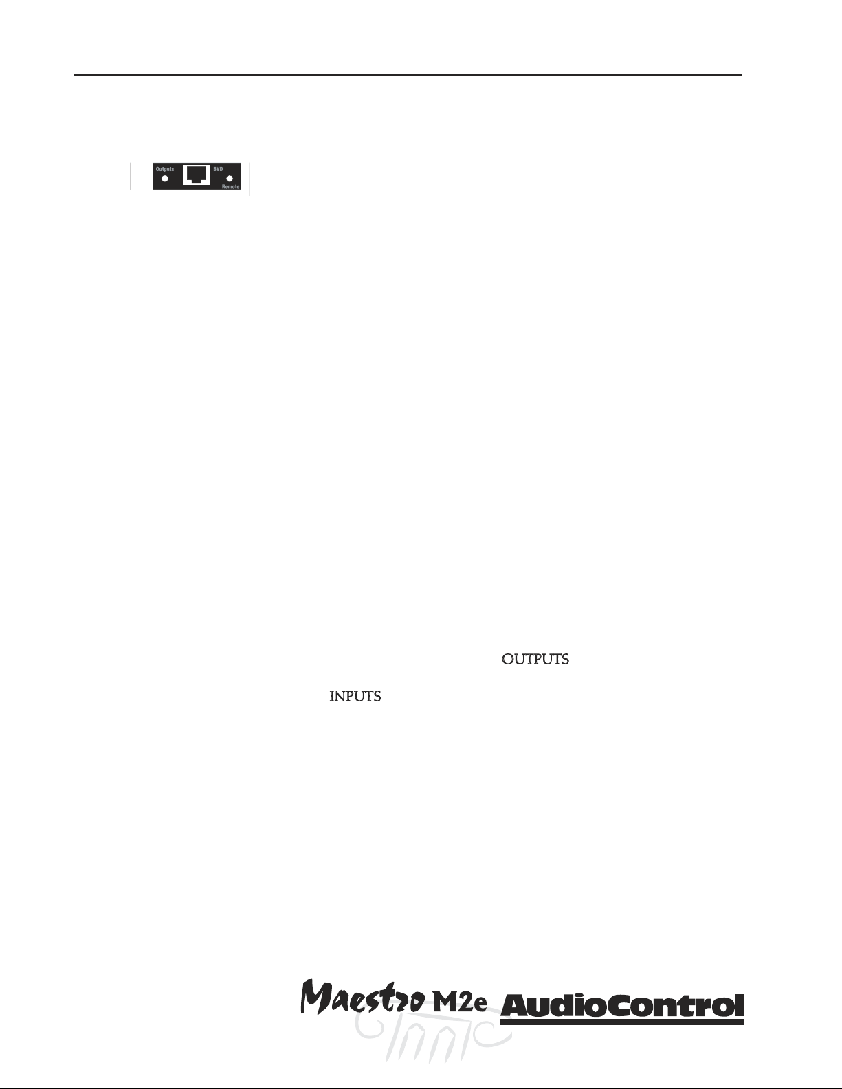
Active Balanced Video Outputs
If you are running your video signals a long distance (i.e.
greater than 50’) than you should consider the Active
Balanced Output on your Maestro M2e. This RJ-45 connector uses CAT-5 wiring to send a signal to an optional
AudioControl balanced line receiver, such as the BVR-25 or
BVR-20. Additionally the CAT-5 can also transmit a digital
audio signal or provide remote power for the BVR-25. The
switch conveniently located next to the RJ-45 connector allows you to select the proper output configuration.
For reference, AudioControl’s Active Balanced Technology is
based on the balanced signal distribution format, which is
the standard in the professional video and audio environments. Because of their design, balanced transmissions
inherently reject the vast majority of hum, noise, or distortion introduced along the signal path. Additionally, the Active circuitry used in AudioControl’s products allows high
quality video and audio strength to be maintained over
longer distances than traditional passive devices.
Video Transcoding
To simplify your installations, the Maestro M2e provides
video transcoding which routes the S-video and composite
signals to the Component outputs of your Maestro M2e.
The following video translation is available:
OUTPUTS
ACTIVE
INPUTS COMPOSITE S-VIDEO COMPONENT BALANCED
COMPOSITE Yes Yes Yes Yes
S-VIDEO Yes Yes Yes Yes
COMPONENT No No Yes Yes
High quality conversion between the various video signal
connection formats is a tricky thing and best left to dedicated video processors.
20
tm
®
Phone 425-775-8461 • Fax 425-778-3166
Page 21
HDMI Signals
The HDMI inputs and outputs on your Maestro M2e accept
digital video signals.
Input Configuration
The Component video inputs are fully assignable to the
sources. This allows you to configure the Maestro M2e to
accept the video input from a particular source unit on one
of the three Component video inputs.
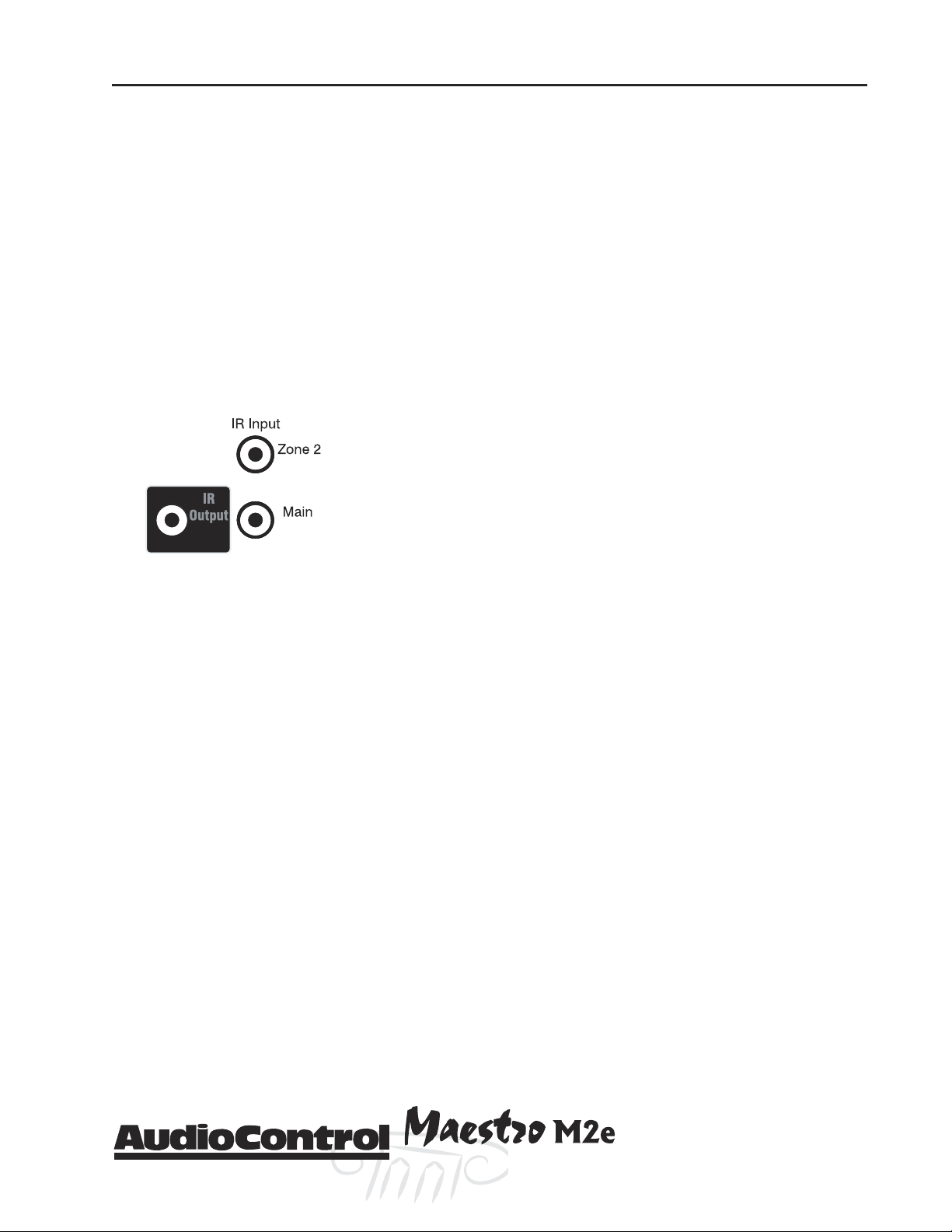
IR Remote Control Connections
Since the Maestro M2e is often hidden away in some dark
closet or equipment rack, we have provided connections
for external IR remote control receivers and emitters. This
allows you to place the infrared receiver where it can “see”
the signal from the remote control. The Zone 2 IR input
controls the second zone functions of the Maestro M2e and
also repeats commands to the source units through the
emitter output.
Set-Up & Configuration
The IR receiver input connections are wired with a 3 conductor 3.5mm jack. The signals are compatible with thirdparty receivers such as a Xantech No. 291-10.
AudioControl does not supply the IR receivers or emitters to
use with the Maestro M2e.
TIP IR Signal
RING Ground
SLEEVE Current Limited +12 VDC (30 mA max.)
®
Phone 425-775-8461 • Fax 425-778-3166
tm
21
Page 22
Set-Up & Configuration
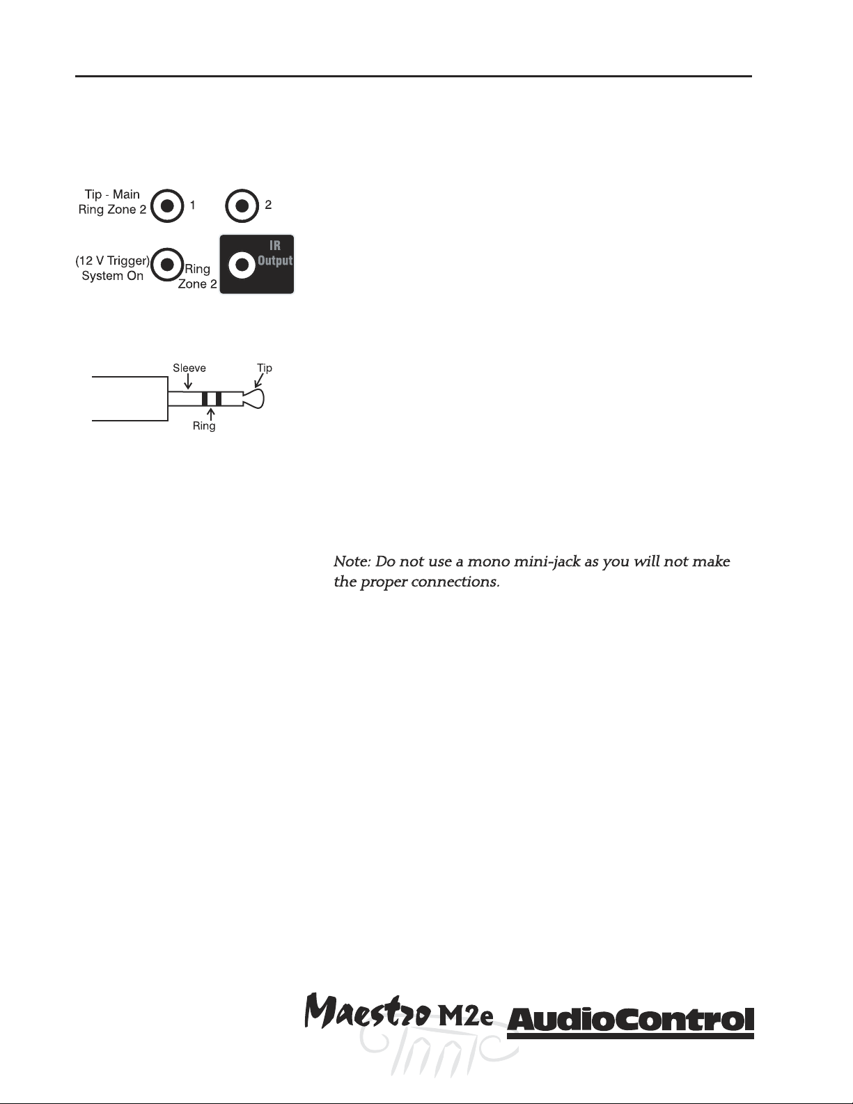
12V Trigger Connections
Video Triggers
Picture of a 3.5m stereo mini-jack connector
There are three stereo mini-jack 12 volt trigger outputs on
the rear panel of the Maestro M2e which are used to remotely control such things as the power amplifier turn-on,
projector power, screens or curtains. The “System On” Trigger has two separate outputs. The jack is a three conductor;
Tip, Ring, Sleeve connection.
TIP Main Zone On (12V, 30mA)
RING Second Zone On (12V, 30mA)
SLEEVE Ground (0V)
The two video triggers carry one signal each. Video Trigger
#1 has 12 volts DC when the Maestro M2e is turned on.
Video Trigger #2 jack goes to 12 volts when one of the video
sources is selected and is generally only used with European (SCART) video devices.
The Main “System On” Trigger would generally be used to
control the power to the amplifiers and source units. The
Video Trigger would be used to control the projector or
video screen.
Note: Do not use a mono mini-jack as you will not make
the proper connections.
Second Zone Connections
The Zone 2 outputs on the Maestro M2e send an independent audio and video signal to a second room. There is a 2
channel stereo analog audio output and a composite video
output.
There is also an IR sensor input for the second zone. This
enables you to remotely control the Maestro M2e and also
repeats the IR to your source units through the IR Output
jack on the Maestro M2e. Any IR signal received through
the Maestro M2e’s front panel IR sensor or through an IR
sensor connected to the IR inputs is repeated to the IR Output for controlling the source components in your system.
22
Since the Zone 2 outputs of the Maestro M2e are 2 channel
analog audio and composite video, you must have these
signals connected from your source units to make them
available. The Maestro M2e does not convert a digital audio
signal into analog for zone 2.
tm
®
Phone 425-775-8461 • Fax 425-778-3166
Page 23

Navigating the Main User Menus
1. Press the Menu button to enter the Main Menu Screens.
2. Rotate the Multi-Function Knob to select Menu 1, 2 or 3.
3. Press the t (Mode) and s (Effect) buttons to select the
4. Use the Multi-Function Control Knob to step through the
5. Press the Menu button to exit the Main Menu Screens.
Main Menu Screen 1 – Inputs and Volume
Main Menu Screen 1
Vol:
----I----------- 29dB
Audio Input:FM
Video Input:VCR
Video Type:4.3
Stereo Direct:On
Bass N/A
Treble N/A
Bal: ------I------ 0dB
Main User Menus
Selecting around the Main Menus is a very simple and intuitive feat.
menu options.
setting options.
VOLUME: Allows adjustment of the Main zone volume while
in the Menu Screens.
AUDIO INPUT: Selects the currently active audio source input.
VIDEO INPUT: Selects the currently active video source input.
VIDEO TYPE: This setting is only applicable to TVs being fed a
SCART signal, typically only used in Europe.
STEREO DIRECT: Enables the Stereo Direct mode. This is the
same as pressing the Direct button.
BASS AND TREBLE TONE: Adjusts the tone control of the front
Left and Right channels.
BALANCE: Adjusts the left/right balance of the front outputs.
Main Menu 2 – Audio Settings
COMPRESSION: Compressing the dynamic bandwidth of the
Main Menu Screen 2
Compression: Off
Lyp Sync.: +00ms
Pro LogicII Music Mode:
Dimension: +3
audio can be a good thing, especially for those late night
action movie festivals. Compression increases the volume
of quiet sections and reduces the volume of the louder
sounds.
There are three settings for the compressing:
Off: No Compression
Center Width: +3
Panorama: 0
Phone 425-775-8461 • Fax 425-778-3166
Medium: Just a little off the top
High: Keeps the sound down and won’t wake the kids.
LIP SYNC: Many video processors and line multipliers cause
a slight delay between the sound and the video picture.
Highly compressed video signals such as MPEG encoded
®
tm
23
Page 24
Main User Menus
satellite receivers and some DVD’s also suffer from this
problem. The Lip Sync setting delays the audio a small
amount to allow the video image to catch up.
PRO LOGIC IIX MUSIC MODE: Pro Logic II/IIx provides a more
detailed surround decoding from two channel analog audio sources than the previous Pro Logic modes. There are
several adjustments to get the best sound imaging from the
ProLogic II/IIx mode:
DIMENSION – Adjusts the depth of the front/rear soundstage.
For normal listening this should be set to +3. If you find
the sound too spacious, turn this setting towards 0, if the
sound is flat and you want more depth from front to rear,
turn the adjustment up towards +6.
CENTER WIDTH – Determines how strongly the Pro Logic II de-
coder processing creates the center channel image. Normally this signal is fed only to the center channel speaker
output, but if the center speaker is set to “None” in the
speaker setup, a phantom center channel is created from
the front left and right channels. Normally this setting is
left at +3.
PANORAMA MODE – When the Panorama Mode is enabled, the
Main Menu 3 – Zone 2 Settings
Main Menu Screen 3
Zone 2 Vol:
---------I------ 50dB
Zone 2 Source:
DVD
front center image is extended to include the rear surround speakers. This provides a more enveloping wraparound effect.
ZONE 2 VOL: Controls the current volume on the Zone 2
audio outputs.
ZONE 2 SOURCE: These options allow listening to a different
source on Zone 2 than on Zone 1.
24
tm
®
Phone 425-775-8461 • Fax 425-778-3166
Page 25

Advanced Setup Menus
Entering the Setup Mode
Advanced Setup Menus
Setup Menu Index
Basic Advanced
1.General 1.Speaker EQ
2.Spkr Size 2.Video
3.Subwoofer 3.Digital
4.Delays 4.Zone 2
5.Level Set 5.Input Trim
6.EX 6.HDMI
Save Setup Exit Menu
Navigating the Setup Menus
1. Use the arrow buttons s (Mode) and ▼ (Effect) to step
2. Use the Volume Control Knob to go between “Basic” and
3. Use the “Select” button to pick a menu item
4. Use the Volume Knob to step through the setting options.
2. When finished, press the Menu button.
3. Use the Volume Knob to choose Save or Exit with Saving
To enter the System Setup menus: Press and Hold the Menu
button for at least two seconds. The main “Setup Index will
be displayed on the Maestro M2e and the video display
connected to the Main Video Outputs. Please note that it is
easiest to go through the advanced set-up menus when the
Maestro M2e is connected to a video display device so all
menu options are shown.
Once you have entered the Setup Menu Index:
through the menus.
“Advanced” menu items
4. Press Select to choose the option and exit the setup menu.
Configuring The Maestro M2e
1. General Settings
1. General Settings
Max Volume: 100
Max On Volume: 70
Delay Units: Time
OSD Mode: Full Page
Video Status:SCRN CTRL
HQ Video: YUV
MAX VOLUME - This limits the highest volume that the
Maestro M2e will play. This is useful if you have speakers or
amplifiers of limited power handling abilities.
MAX ON VOLUME - This is the highest volume that the Maestro
M2e will play when first turned. This prevents the Maestro
M2e from being turned on at shock volume levels from the
last time you were watching a good movie.
DELAY UNITS - The settings can be adjusted in English (Inches),
Metric (Centimeters), or Time (milliseconds). Important Installation Note: When you change the Delay Units, all delay
settings are returned to “0”. Make certain you choose your
preferred units BEFORE adjusting the delays.
®
Phone 425-775-8461 • Fax 425-778-3166
tm
25
Page 26
Advanced Setup Menus
OSD MODE - The On-Screen Display (OSD) can be displayed
in either Mixed mode where the white text is overlaid onto
the video image, or in Full Page mode where the video image is temporarily replaced with a black background.
VIDEO STATUS - Sets the operation of the 12 volt trigger out-
puts. For normal operation, leave this set to Screen Control
as it enables the Main and Video Trigger outputs to operate
for equipment control triggers. The SCART option is only
used on European video equipment to control external
video switching and scan-rate converters.
HQ VIDEO - Choose the operation of the OSD to match your
video projector or display. Typical high-end video systems
use YUV (aka Component Video (Y, PB, PR)) for their signals.
Don’t confuse the colors on the RCA cables used to connect
the video equipment with the format. Many Component
video cables have their connectors colored red, green and
blue even though they are not sending an RGB signal. The
RGB (Red, Green, Blue) signal format is more common in
Europe.
2. Speaker Sizes
2. Speaker Sizes
Auto Setup: Config1
Front L/R: Small
Centre: Small
Surr L/R: Small
Surr.Back L/R: Small
Sub Woofer: Present
5.1 Rears: Both
For the purposes of setting the Maestro M2e, a “Large”
speaker is one that is capable of reproducing a full range
(20-20KHZ) audio signal. A “Small” speaker is one that
cannot reproduce deep bass frequencies (i.e. typical Satellite speakers typically below 80 Hz). If you do not have a
speaker connected to an output (i.e. No Subwoofer or Back
Speakers) then set that speaker size to “None”.
AUTO SETUP - Allows quickly setting common speaker size
configurations based on the following:
Speaker Config 1 Config 2 Config 3 Custom
Front L/R Small Large Large Sm/Lge
Center Small Small Small Sm/Lge/None
Surr L/R Small Small Large Sm/Lge/None
Surr Back
L/R
Subwoofer Present None Present Present/None
5.1 Rears Both Both Both Surr L/R Surr
Small Small Small Sm/None
Back
L/R/Both
26
tm
®
Phone 425-775-8461 • Fax 425-778-3166
Page 27

Advanced Setup Menus
CONFIG. 1, 2, AND 3 - These are standard speaker combinations for home theater systems.
3. Subwoofer Settings
3. Subwoofer Settings
Stereo Mode: Large
Cross-Over Freq: 80Hz
Sub Stereo: -----I 0dB
LARGE: All of the stereo audio is passed to the Left and
LARGE + SUB: Same as above, but bass is also sent to the
DTS LFE Gain: 0dB Normal
7.1 Sub Level:
SAT + SUB: Provides full bass management when you are
0dB Normal
CUSTOM -
5.1 REARS - This defines how a 7.1 channel installation will
utilize the surround speakers.
SURR L/R - Sends all of the decoded surround information
to the Surround Left/Right outputs. No audio is sent to the
Back outputs.
SURR BACK L/R - Sends the surround audio to the Back outputs and nothing is sent to the Surround outputs.
BOTH - Sends the same decoded surround audio to both the
Surround and Back outputs (the surround level is automatically reduced 3dB).
STEREO MODE - This controls how the subwoofer operates in
the Stereo music modes.
Right Outputs. Nothing is sent to the Subwoofers.
Subwoofer. This provides additional punch to the bottom
end.
using smaller satellite-type front speakers. The lower bass
frequencies are cut off from the Left and Right Outputs
and sent to the Subwoofer Outputs.
This gives you full control over each speaker channel.
CROSSOVER FREQUENCY - This controls the frequency at which
bass is redirected from speaker channels set to “Small” and
sent to the Subwoofer outputs. This frequency is adjustable
from 40 Hz to 130 Hz in 10 Hz increments.
SUB STEREO - This adjusts the relative level of the subwoofer
channels in the Stereo Music modes. Your personal tastes
should be the guideline for this adjustment after the other
levels have been properly calibrated.
DTS LFE GAIN - Older DTS soundtracks have a LFE (subwoofer) soundtrack recorded 10 dB lower than Dolby Digital. The
-10dB setting boosts the DTS LFE soundtrack to the same as
other formats. The 0 dB setting leaves the DTS LFE channel
unaffected.
®
Phone 425-775-8461 • Fax 425-778-3166
tm
27
Page 28
Advanced Setup Menus
4. Delay Settings
4. Delay Settings
Front Left: 0.0ms
Center: 0.0ms
Front Right: 0.0ms
Surr. Right: 0.0ms
Surr. Back Right:
Surr. Back Left:
Surr. Left: 0.0ms
Subwoofer: 0.0ms
0.0ms
0.0ms
7.1 SUB LEVEL - The decoded subwoofer output channel of a
DVD-A player is typically 10 dB lower that the other channels. The +10dB option boosts the subwoofer signal by
10dB. The 0dB passes the subwoofer channel unaffected.
The Speaker Delay settings help the sound from each
speaker arrive at the listening seat at the same time. This
provides a much more believable and immersive sound
environment. Precise delay settings should be done by a
trained professional with audio test equipment such as the
AudioControl Iasys HT to measure the actual sound delay.
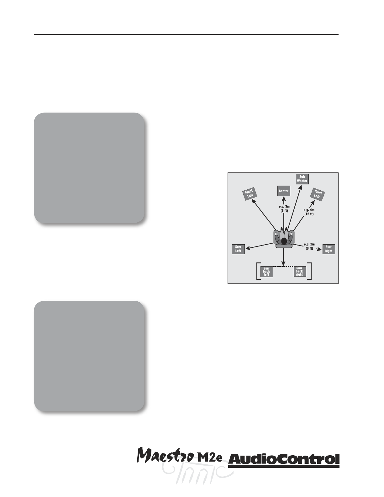
You can get a rough
delay setting using an
assistant and a tape
measure. Measure the
distance from the center of a speaker to the
seated ear position of
the main listening seat.
Write each of these distances down and enter
them into the Maestro
M2e.
5. Level Settings
5. Level Settings
Test Tone Cycle:Manual
Front L: ---I--- 00dB
Center: ---I--- 00dB
Front R: ---I--- 00dB
Surr. R: ---I--- 00dB
Surr. BR: ---I--- 00dB
Surr. BL: ---I--- 00dB
Surr. L: ---I--- 00dB
Subwoofer:---I--- 00dB
28
It is critical to properly match the levels from each speaker
to achieve a correct sound stage. The realism is totally
lost if the footprints of a person walking across the screen
change in volume as they move from left to center to right.
We strongly recommend using a test analyzer such as our
IasysHT for this calibration. The levels are nearly impossible
to judge by ear alone. Though not as accurate as using the
Iasys HT, you can use a sound level meter fro this adjustment.
With the internal test noise generator of the Maestro M2e,
adjust each speaker for a sound pressure level (SPL) of 75
dB using a “slow” response time on the SPL meter placed at
the main listening position at ear height. Use the Mode and
Effect buttons on the Maestro M2e to select a speaker chan-
tm
®
Phone 425-775-8461 • Fax 425-778-3166
Page 29

6. EX Settings
6. EX Settings
Surr. EX: Manual
Use Channels 6+7 For:
DD Surr EX
AUTO DD EX - The Maestro M2e will automatically switch
Advanced Setup Menus
nel, then adjust the volume of that speaker with the MultiFunction control knob.
The Test Tone Cycle setting is normally used on Manual.
The Automatic option is used for a quick check by ear after
you have manually calibrated the levels. The Automatic option steps through all the speakers with a two second burst
of test noise. Sitting in the main listening position, adjust
the individual channel setting so that you do not hear any
change in volume level as each speaker is played.
SURR. EX: When playing Surround Ex encoded material, the Maestro M2e gives you the option of either
Manually(Manual) or Automatically(Auto) selecting the
Surround settings.
to Surround Ex decoding when Surround EX material is
detected. Set this option to Manual if you want to control
which mode is used by the Maestro M2e.
AUTO PLIIX MOVIE - The Maestro M2e will automatically
switch to Pro Logic IIx Movie decoding when appropriate material is detected. Set this option to Manual if you
want to control which mode is used by the Maestro M2e.
MANUAL - The Surround Ex mode can only be selected us-
ing the optional AudioControl MX-500 remote control or
via the RS-232 port.
USE CHANNELS 6+7 FOR:
DOLBY DIGITAL SURR EX – In this mode, amplifier channels 6
and 7 drive the two additional rear EX speaker channels
BIAMP L+R – This mode allows you to bi-amplify your
front speakers which, with the addition of additional amplification, helps you improve the performance of these
speakers.
®
Phone 425-775-8461 • Fax 425-778-3166
tm
29
Page 30
Advanced Setup Menus
Advanced Setup Menus
Adv1 - Speaker Eq
ADV 1 - Speaker Eq
Bass Treble
All--I-- 0dB --I-- 0dB
FL --I-- 0dB --I-- 0dB
C --I-- 0dB --I-- 0dB
FR --I-- 0dB --I-- 0dB
SR --I-- 0dB --I-- 0dB
SBR--I-- 0dB --I-- 0dB
SBL--I-- 0dB --I-- 0dB
SL --I-- 0dB --I-- 0dB
ADV 2 - Video Settings
AUTO Tone Bypass: Yes
ON: All volume control, source selection and setting options
Adv2 - Video Settings
OFF: Only the Main and Setup menus are displayed.
Zone 1 OSD: On
Video Input Tape: None
Video Input CD: None
Video Input FM: None
Video Input AM: None
Video Input DVD-A:DVD
Input: Button:
HQ Vid DVD:DVD
HQ Vid AV :AV
HQ Vid Sat:SAT
CHANNEL EQUALIZATION - For simple tone control, we have
included Bass and Treble adjustments on the Maestro M2e
for each channel with 6 dB in boost or cut. To get the best
performance from a home theater system, we strongly recommend the use of a good equalizer such as our Diva.
AUTO TONE BYPASS: - Set this option to Yes to automatically
defeat the above tone control settings when in the Stereo
music mode.
ZONE 1 OSD: -
are displayed on the main video outputs.
ASSIGNING COMPOSITE AND S-VIDEO INPUTS: - Allows for advanced
video settings and specifically for assigning a video input to
a source with no actual video output. You can assign DVD,
SAT, AV, Aux, or VCR to any of these audio inputs or select
None.
ASSIGNING COMPONENT VIDEO INPUTS - The HQ Video option lets
you assign audio sources to the high quality component
video inputs. Select the source input you want associated
with each of the component video inputs.
Controls the display of the On-Screen Display.
ADV 3 - Digital Settings
Adv3 - Digital Settings
Coaxial inputs
Input: Button:
DVD: DVD
CD: CD
AV: AV
Optical inputs
Input: Button:
SAT: Sat
AUX: VCR
Tape: Tape
30
ASSIGNING THE DIGITAL AUDIO INPUTS - The Digital Audio inputs
on the Maestro M2e are fully assignable. Any digital input
can be assigned to any source selection. Only one source
can be assigned to a digital input. When planning your installation you should identify whether each source unit has
a Coaxial Digital, Optical Digital or No digital output.
tm
®
Phone 425-775-8461 • Fax 425-778-3166
Page 31

ADV 4 - Zone 2 Settings
Adv4 - Zone 2 Settings
Zone2 Vol:
--------I-------- 36dB
Max Vol 20-83: 83
Fix Vol: No
Max On Vol: 50
Standby: Local Only
Access: ALL
Advanced Setup Menus
MAX VOLUME - This works just like the Main Zone maximum
volume setting back in the basic menus. It limits the maximum volume control setting for the Zone 2 output.
FIXED VOLUME - If you are using the Zone 2 output from the
Maestro M2e to feed into another stereo receiver in the
remote zone, you will want to set this option to Yes. This
provides a constant signal level so you can use the volume
control on the receiver in the second zone to control it’s
volume. Install Hint: Set the desired output volume level
for Zone 2 with the volume control before setting this option to on. The Maestro M2e locks the Zone 2 output at the
current volume setting when this option is set to on.
MAX. ON VOLUME - Sets the maximum volume that the Zone
2 output will play when the power is turned on.
STAND-BY - Allows Main Zone (zone 1) to be put into standby either locally or by zone 2.
LOCAL ONLY – Only the main zone switches into stand-by
ALL OFF – Both the main zone and Zone 2 can be switched
ADV 5 - Input Trims
Adv5 - Analogue Settings
DVD: Low 0.5V
Sat: Low 0.5V
AV: Low 0.5V
AUX: Low 0.5V
VCR: Low 0.5V
Tape: Low 0.5V
CD: Low 0.5V
from main zone
into stand-by from the main zone.
ACCESS - Limits which sources are available to Zone 2. To set
this option: Press the source input buttons to toggle a selection on or off using the optional remote control.
Adjusting the Source Unit Input Volume Trims - The input
trims allow the installer to match the relative volumes of
all sources so when you switch from one source to another
the relative volume level will be balanced. These trims affect only the two channel analog audio inputs from each
source. There is no change to the digital audio levels.
The available output options are Low .5V, Medium 1V, Reference 2V and High 4V. The reference 2 volt setting should
be appropriate for most sources. To set the levels for a
source, select a loud music selection or use a 0dB reference
disk and switch between sources. If one source is noticeably louder or quieter than others, make the appropriate
level settings to that source.
®
Phone 425-775-8461 • Fax 425-778-3166
tm
31
Page 32
Advanced Setup Menus
Adv6 - HDMI Settings
ADV 6 – HDMI Settings
Input: Button:
DVD: DVD
SAT: Sat
Saving Settings and Exiting Set-up
Setup Menu Index
Basic Advanced
1.General 1.
2.Spkr Size 2.Video
3.Subwoofer 3.Digital
4.Delays 4.Zone 2
5.Level Set 5.Input
Trim
6.EX 6.HDMI
1. Press the “Menu” button
Speaker EQ
2. Turn the volume knob to select between “Exit Setup” and
3. Press the “Select” button
The HDMI switching on the Maestro M2e is strictly for
routing digital video signals so you will need to assign an
audio input to each of the HDMI digital video inputs that
you are using. This will allow the user to enjoy the highest possible audio and enables the installer to change the
source input names for the front panel and on-screen displays.
Once you are done editting your set-up menus you should
now save your settings and/or exit the Set-Up menu.
“Save Setup”
Save Setup Exit Menu
32
tm
®
Phone 425-775-8461 • Fax 425-778-3166
Page 33
Operating the Maestro M2e
Now that you have everything connected together and configured properly, it’s time to sit back and enjoy the fruits of
your labor. Since the Maestro M2e gives you two independent “zones” to view and listen to your system (the Main
home theater zone and the remote Zone 2) we’ll cover
them separately. The primary difference between the two
zones is that there is multi-channel surround sound for the
Main zone and two channel stereo in the second zone.
Main Zone
All operation of the Maestro M2e can be done with either
the front panel display or the On-Screen Display (OSD) on
the video display. The OSD is simpler to use since the larger
display allows all the menu options to be listed at once.
Operating the Masestro M2
Turning the Maestro M2e On
There is actually two levels of turning the Maestro M2e on.
First, the rear panel Power switch button must be selected.
This turns on the AC power to the Maestro M2e. In most
systems this power switch will ALWAYS be left on so the
theater automation system can control the Maestro M2e.
When the Maestro M2e receives a power off command
from the IR or RS-232 inputs it goes into a sleep Standby
mode. The Maestro M2e is a very light sleeper and will
wake back into normal operation by pressing any source
input button or sending a “power on” command to the IR
or RS-232 inputs.
®
Phone 425-775-8461 • Fax 425-778-3166
tm
33
Page 34

Operating the Masestro M2
Choosing your Input Using the Main Menus
Choosing your Input
Simulcast Listening
The three Main Menus of your Maestro M2e enable the user
to make basic changes in the operation of the Maestro M2e.
The Source selection buttons beneath the main Maestro
M2e display choose the source component that you want
to view or listen to. There are ten sources available on the
Maestro M2e. When configuring the Maestro M2e, there
are several options to reassign the digital audio and video
inputs to different sources.
It is simple to choose separate audio and video sources with
the Maestro M2e which allows you to watch one source
and listen to the audio from another. From the Operation
screen on the Maestro M2e
1. Press the Menu button to enter the Main Menu Screen 1:
Inputs and Volume.
2. Press the ▼ (Effect) until you see Audio Input.
3. Press a Source Button to choose the Audio input source.
4. Press the ▼ (Effect) again and you will see Video Input.
5. Press a Source Button to choose the Video input source.
6. Press the Menu button to exit the Main Menu Screen 1.
7. These input selections will stay in effect until you press a
Source Button to choose another source. The Video input
will automatically return to tracking the Audio source.
VCR and Tape Operation
The Maestro M2e has full independent recording loops for
a VCR and Tape Deck. Both of these inputs allow recording
separately from the one that you are listening to. Pressing
the Tape button while another source is active enables you
to continue recording that source, but monitor the output
of the recording deck. Both source LEDs on the front of the
Maestro M2e will be lit.
34
tm
®
Phone 425-775-8461 • Fax 425-778-3166
Page 35
Stereo Direct
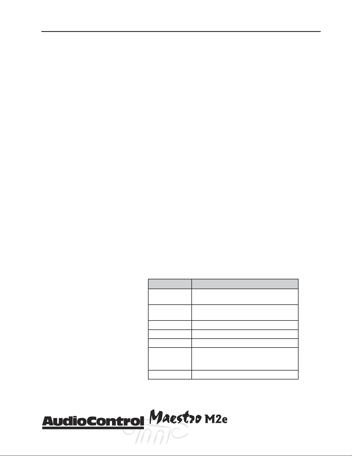
For two-channel analog listening, the Maestro M2e features
a Stereo Direct input mode. This mode defeats all digital
processing and passes an analog direct two channel audio
signal from the input source to the main amplifier outputs
of the Maestro M2e. Most of the digital circuitry in the
Maestro M2e is bypassed when in the Stereo Direct mode.
Setting the Surround Modes
When listening to a source, the Mode button toggles between the available Surround Decoding Modes (Mono,
Stereo, Pro Logic II, DTS Neo, Dolby Digital, etc.). The modes
available will change depending on the source materials
encoding. Refer to the manual section on Surround Modes
for more details about each mode.
DSP Effects
Operating the Masestro M2
The Maestro M2e isn’t all work and no play. When listening
in the “Stereo” mode, the Maestro M2e features several DSP
effect modes to simulate different listening environments.
These effects provide varying amounts of delay and reverberation so your theater will sound completely different.
Try them out at your next party. Refer to the manual section on Surround Modes on page 42 for more details about
the DSP effects.
Effect
None No effects active, stereo
Music Extracted ambience and
Party All speakers on
Club Small room
Hall Medium reverberant room
Sport Very reverberant with
Church Long reverberant room
Description
signal
center information
extracted ambience and dry
center dialog
®
Phone 425-775-8461 • Fax 425-778-3166
tm
35
Page 36

Operating the Masestro M2
Display Brightness
Second Zone
Because everybody has different preferences in how the
equipment in their home theater should look, we have
provided a control over the brightness of the main Maestro
M2e display. This button toggles between three display levels: Bright, Dim and Off. In the Off mode, the display will
momentarily come on when any button is pressed or the
volume is changed and then return to the blank off state
The Zone 2 outputs provide a means for listening and viewing your home theater components in another room. The
source selections and volume control for this second zone
is independent of the main theater zone outputs. There are
several options for controlling the second zone: The Main
Menu screen from the Maestro M2e, the external RS-232
serial control port, or the IR remote control.
The Zone 2 video output has an On-Screen Display and
setup menu independent of the Main video outputs. This
screen displays the current source selection status for Zone
2 along with the current Zone 1 settings. Depending on the
Advanced Zone 2 settings in the Maestro M2e configurations, you may not be able to change the Zone 1 settings
from Zone 2. See page 21 for more detailed information.
36
tm
®
Phone 425-775-8461 • Fax 425-778-3166
Page 37

Surround Modes
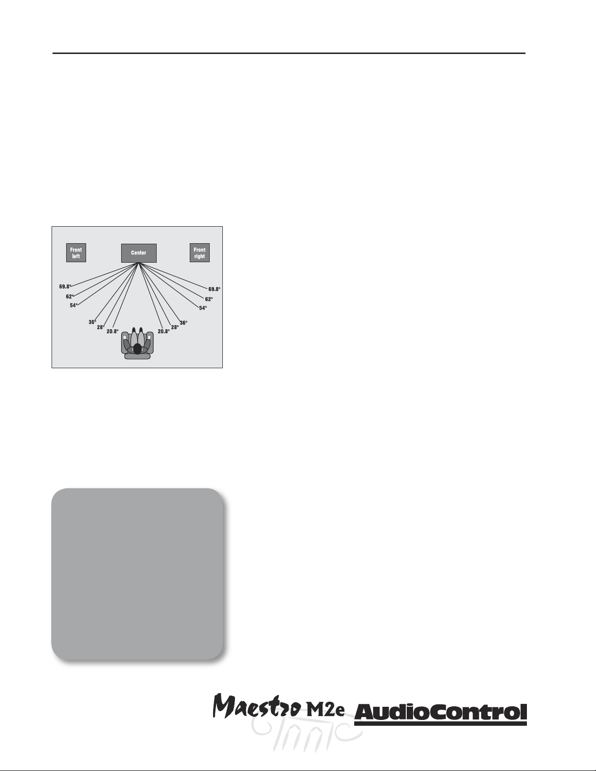
The Maestro M2e theater processor contains a powerful digital signal processor (DSP) that enables the Maestro M2e to
decode multiple digital and analog multi-channel surround
sound formats. Since the Maestro M2e is fully programmable, new surround decoding formats may be incorporated
as they become popular.
There are two types of surround processing modes in the
Maestro M2e for both digital and analog source material.
These are selected using the Effect and Mode buttons on
the front panel or their equivalent commands in the external control protocols. The Effect button selects special
DSP processing effects for two channel analog sources only.
The Mode button manually selects the surround decoding
mode when the source media does not automatically configure the Maestro M2e.
Surround Modes
There are two different music surround playback methods:
Those that use the internal digital decoding of the Maestro
M2e (Dolby Digital or DTS encoded) and the newer multichannel audiophile Super Audio CD (SACD) and DVD-Audio
formats that have the decoding built into the players. The
SACD and DVD-A formats bypass all internal processing in
the Maestro M2e and feed directly to the amplifiers through
the volume control. Since the digital processing in the
Maestro M2e is defeated, there are no mode adjustments
available. The Dolby Digital and DTS encoded music disks
are treated the same as surround encoded movies and have
the same options.
Modes for Digital Source Material
Digital surround recordings have details of their decoding
requirements encoded into the media. The Maestro M2e
automatically detects this information and switches to the
appropriate surround mode.
The following modes are available for multi-channel digital
sources. Special modes such as DTS ES and DTS 6.1 Discrete
are only available from properly encoded source materials.
®
Phone 425-775-8461 • Fax 425-778-3166
tm
37
Page 38

Surround Modes
Dolby Digital 5.1
This is the most commonly used surround format for DVD,
Digital Satellite and Broadcast television. Dolby Digital 5.1
delivers surround sound with five discrete full-range channels
and a low frequency bass effects (LFE) subwoofer channel.
DTS 5.1
The DTS 5.1 mix is less common that the Dolby Digital
format, although it is generally acknowledged to having
superior sound quality. It has the same five full range channels plus the subwoofer channel.
DTS-ES
DTS ES is a 5.1 channel format based on DTS 5.1. There is
an additional center rear channel that is matrix encoded
into the rear surround channels for playback.
DTS-ES 6.1 Discrete
This is a true discrete 6.1 channel sound format. Unlike
DTS ES, this format has a true sixth channel mixed into the
soundtracks. The DTS 6.1 Discrete mode only operates on
sources with DTS 6.1 encoding. A list of available DVD titles
with DTS ES and 6.1 Discrete can be found at www.dtsonline.com
DTS Neo:6 Cinema
A movie surround decoding mode designed to provide a
movie theater environment soundstage with natural steering to all available surround channels.
DTS Neo:6 Music
Similar to the Cinema mode but with a tighter surround
effect for most musical material.
DSP Effects Modes
The Maestro M2e has several DSP effects modes to enhance
playback of a two channel audio source through the surround speakers. These modes are only available on stereo
audio sources.
38
tm
®
Phone 425-775-8461 • Fax 425-778-3166
Page 39

Effects Modes
MUSIC - Music surround makes full use of the additional
speakers in a theater system. This effect uses ambience
extraction for the side and rear speakers and offers the most
subtle surround processing with no reverberation or reflection sounds.
PARTY - The Party mode allows unprocessed stereo signals
to be played over all the speakers for background music or
maximum sound levels.
CLUB - The Club effect generates reflections and short reverberation to the front, side and rear speakers. It simulates a
small night club venue.
CONCERT HALL - The Concert Hall effect generates the ambient
information of a medium sized performance hall. Reflections and medium length reverberation information is sent
to all channels.
Surround Modes
SPORTS - The Sports Stadium effect is ideal for watching
live sporting events. The open ambience is actively created
around you. The center channel is used for the dialog commentary.
CHURCH - The Church effect uses a reverberation algorithm
that emphasizes the smooth, rich reverberant sound of a
large space. As the name suggests, it works well for simulating the long reverberation of a cathedral or church.
Modes for Analog Source Material
Two channel analog audio source material does not contain
surround encoding information. This means that you will
have to manually choose the surround mode that you find
sounds best.
Two-channel Audio Source Modes
The following surround modes are available with two
channel audio sources. These include Stereo Analog, Dolby
Digital 2.0 and PCM 2-channel digital sources.
Mono
The left and right channels are combined into a single
mono mix. This can benefit some older recordings and
video tapes.
®
Phone 425-775-8461 • Fax 425-778-3166
tm
39
Page 40

Surround Modes
Stereo
The Maestro M2e works like a traditional audio preamplifier
in this mode. This mode plays back analog audio sources
along with 2 channel digital sources such as Dolby Digital
2.0 from some DVD players and PCM digital CDs.
Dolby Pro Logic II/IIx
This provides better surround channel separation than the
original ProLogic format. There are two ProLogic II surround
modes: Music and Movie. Use the method that sounds best
to you.
Dolby Pro Logic Emulation
This mode should only be used on ProLogic encoded source
materials. ProLogic processing on pure stereo sources can
sound muffled and is not recommended.
Mode Memory
The Maestro M2e automatically remembers the last surround mode used for each source input. Since most digital
surround recordings have control information encoded
into them; the Maestro M2e will switch to the decoding
method requested by the source material.
Some Dolby Digital Surround EX soundtracks are missing the digital flag the enables automatic switching. If you
know that a movie you are watching is encoded in Surround EX, you can manually select the THX Surround EX
surround mode with the THX button.
A list of available DVD titles encoded with Dolby Digital
Surround EX technology can be found at www.thx.com or
www.dolby.com.
40
tm
®
Phone 425-775-8461 • Fax 425-778-3166
Page 41

Automation Integration
Introduction
Part of the joy of a great home theater is that you don’t
have a tray of remote controls staring at you whenever you
want to watch a movie. Hidden away behind the scenes is a
workhorse that takes care of the mundane tasks of turning
on all the components, lowering the curtains, dimming the
lights, popping the corn, etc. This faithful servant can take
the form of a simple learning remote control or a system as
capable as a whole house automation system with touchscreens. There is a wide variety of theater controllers available.
There are two means of remotely controlling the Maestro M2e: With Infrared (IR) Remote control and with the
RS-232 Serial Port. Both of these methods feature a very
extensive library of commands. It is really up to the system designers choice of user interface as to which of these
methods will be used. It is possible to use both of these in
the same installation depending on your needs.
Automation Integration
Infrared Control versus RS-232
Infrared remote control systems are typically less expensive
than RS-232 controllers. Their main limitation is that Infrared is strictly line-of-sight. That means that there has to be
an unobstructed view between the controller sending the
infrared commands and the IR sensor or front panel of the
Maestro M2e. When you try to send long groups of commands (macros) such as: Turn on the TV, Turn on the Maestro M2e, Turn on the DVD, Select the DVD Input on the
Maestro M2e, Play the DVD; everything can easily get out
of sync if you sit down the IR controller or somebody walks
in front of you before all the Infrared commands have been
sent. Infrared is also typically a one-way communication.
There is no way for the IR remote to know if the command
was received correctly.
RS-232 Serial control is a hard-wired connection. There
is usually a wire connecting the user interface (keypad or
touchscreen) to the controller system. Then another wire
connecting the controller system to the Maestro M2e. RS232 is also a two-way communications scheme. This allows
®
Phone 425-775-8461 • Fax 425-778-3166
tm
41
Page 42
Automation Integration
RS-232 Serial Control
the controller system to send very long, complex strings of
commands and get an answer back to know that all those
commands were executed properly.
You must set the external RS-232 control system serial port
to match the data communication speed and format of the
Maestro M2e. If these settings are not correct, the Maestro
M2e will not respond to the commands.
Maestro M2e communication parameters:
Baud Rate: 38,400
Start Bit: 1
Data Bits: 8
Stop Bit: 1
Parity: None
Flow Control: None
Cable Wiring
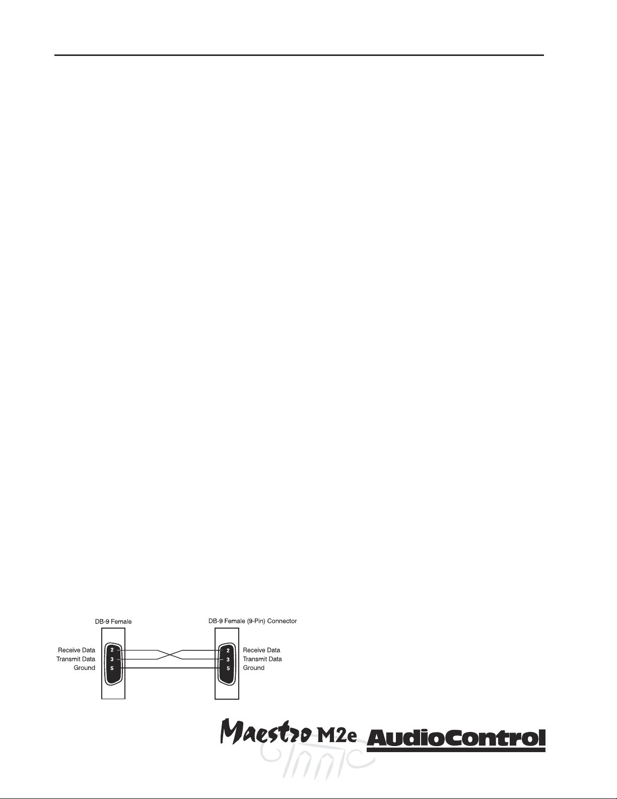
The cable wiring to connect the Maestro M2e to your control system will depend on the RS-232 output connection
on the controller. Make certain that you wire the Transmit
Data output on the serial controller to the Receive Data on
the Maestro M2e and vice versa on the Receive Data line on
the controller system. Connect the signal grounds on the
control system and the Maestro M2e together. The RS-232
connection on the Maestro M2e is a DB-9 Male wired as follows:
Pin 2 Receive Data (RXD)
Pin 3 Transmit Date (TXD)
Pin 5 Ground
To connect the Maestro M2e to a standard PC serial comm
port; wire the cable in a ‘null modem’ arrangement using
the appropriate serial cable.
RS-232 Null Modem Arrangement
42
tm
®
Phone 425-775-8461 • Fax 425-778-3166
Page 43

Automation Integration
Command Structure
The RS-232 serial control protocol structure of the Maestro
M2e is a string of ASCII characters with all Commands terminated with an ASCII carriage return (0xd hexadecimal).
Issuing Commands
Each transmission to the Maestro M2e is seven bytes long
and uses the following format:
<STR><CC><P1><P2><ETR>
Parameter Command Description
STR “PC_” Begins transmission to Maestro M2e
CC see table Command code which determines type of
page 47 function (ie. Power, Volume Control, Zone
Selection, etc.
P1 “1”, “2”, or “~” Specifies which Zone or Tuner
P2 “1 – 9” Represents individual functions based on
the above
Command Code (ie. On, Off, Mute, Source
Selection, Surround Modes)
ETR Carriage Return End transmission
Note: ALL commands are entered in Uppercase.
As an example:
Power up the Maestro M2e: PC_*11 <cr>
®
Phone 425-775-8461 • Fax 425-778-3166
tm
43
Page 44

Automation Integration
Receiving Commands
Parameter Command Description
STR “AV_” Begins transmission
RC Reply code
AC “P” or “R” Answer Code – “P”(command accepted),
“R”(command error)
P1 “1” or “2” Zone – Determines which zone the
command controlled
P2 “1 – 9” Represents individual functions based on
the above
Mute the audio output on the main zone: PC_.10 <cr>
Command processing begins when the first semicolon separator line feed terminator is received. When a command is
executed properly, the Maestro M2e echoes the command
back in the following format:
<STR><RC><AC><Px><ETR>
Command Code (ie. On, Off, Mute, Source
Selection, Surround Modes)
ETR Carriage Return End transmission
As an example:
Confirming Power up of the Maestro M2e: AV_*P11 <cr>
Confirming Mute of the audio output on the main zone:
AV_.P10 <cr>
Manually Determining RS-232 Codes
When attempting to determine a specific command sequence for the Maestro M2e, it is sometime helpful to connect the Maestro M2e to a terminal emulator program (like
Hyperterminal) and utilize the information from the Receiving Command. Physically perform the function on the
Maestro M2e (ie. adjust the volume knob, select a source,
change a surround effect), your Maestro M2e will transmit
a Receiving Command and you can use the command on
your screen to determine the specific RS-232 command.
44
tm
®
Phone 425-775-8461 • Fax 425-778-3166
Page 45
Automation Integration
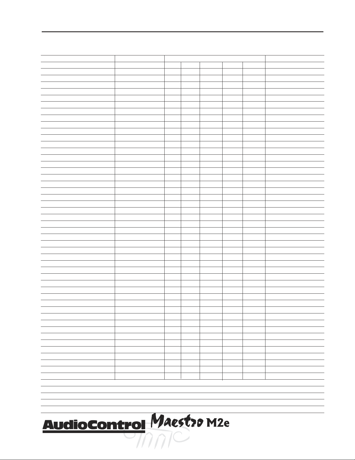
MAESTRO M2e RS232 COMMAND PROGRAMMING GUIDE
Function Selection ASCII Hex
STR CC P1 P2 ETR
Power / Standby On / Off On PC_ * 1 1 (0xd) (0x2a)(0x31)(0x31)
Off PC_ * 1 0 (0xd) (0x2a)(0x31)(0x30)
Request PC_ * 1 9 (0xd) (0x2a)(0x31)(0x39)
Display Brightness Off PC_ + 1 0 (0xd) (0x2b)(0x31)(0x30)
Dim PC_ + 1 1 (0xd) (0x2b)(0x31)(0x31)
Bright PC_ + 1 2 (0xd) (0x2b)(0x31)(0x32)
Request PC_ + 1 9 (0xd) (0x2b)(0x31)(0x39)
Open Menu Main PC_ “, “ 1 1 (0xd) (0x2c)(0x31)(0x31)
Setup PC_ “, “ 1 2 (0xd) (0x2c)(0x31)(0x32)
Trim PC_ “, “ 1 3 (0xd) (0x2c)(0x31)(0x33)
Sub Trim PC_ “, “ 1 4 (0xd) (0x2c)(0x31)(0x34)
Lip Sync PC_ “, “ 1 5 (0xd) (0x2c)(0x31)(0x35)
Request PC_ “,” 1 9 (0xd) (0x2c)(0x31)(0x39)
Close Menu Main PC_ - 1 1 (0xd) (0x2d)(0x31)(0x31)
Setup PC_ - 1 2 (0xd) (0x2d)(0x31)(0x32)
Trim PC_ - 1 3 (0xd) (0x2d)(0x31)(0x33)
Any Open Menu PC_ - 1 4 (0xd) (0x2d)(0x31)(0x34)
Mute - Zone 1 Mute PC_ . 1 0 (0xd) (0x2e)(0x31)(0x30)
Un-Mute PC_ . 1 1 (0xd) (0x2e)(0x31)(0x31)
Request PC_ . 1 9 (0xd) (0x2e)(0x31)(0x39)
Mute - Zone 2 Mute PC_ . 2 0 (0xd) (0x2e)(0x32)(0x30)
Unmute PC_ . 2 1 (0xd) (0x2e)(0x32)(0x31)
Request PC_ . 2 9 (0xd) (0x2e)(0x32)(0x39)
Volume Change - Zone 1 Up PC_ / 1 1 (0xd) (0x2f)(0x31)(0x31)
Down PC_ / 1 0 (0xd) (0x2f)(0x31)(0x30)
Request PC_ / 1 9 (0xd) (0x2f)(0x31)(0x39)
Volume Change - Zone 2 Up PC_ / 2 1 (0xd) (0x2f)(0x32)(0x31)
Down PC_ / 2 0 (0xd) (0x2f)(0x32)(0x30)
Request PC_ / 2 9 (0xd) (0x2f)(0x32)(0x39)
Source Selection Zone 1 DVD PC_ 1 1 0 (0xd) (0x31)(0x31)(0x30)
SAT PC_ 1 1 1 (0xd) (0x31)(0x31)(0x31)
AV PC_ 1 1 2 (0xd) (0x31)(0x31)(0x32)
AUX PC_ 1 1 3 (0xd) (0x31)(0x31)(0x33)
VCR PC_ 1 1 4 (0xd) (0x31)(0x31)(0x34)
CD PC_ 1 1 5 (0xd) (0x31)(0x31)(0x35)
FM PC_ 1 1 6 (0xd) (0x31)(0x31)(0x36)
AM PC_ 1 1 7 (0xd) (0x31)(0x31)(0x37)
DVDA PC_ 1 1 8 (0xd) (0x31)(0x31)(0x38)
Request PC_ 1 1 9 (0xd) (0x31)(0x31)(0x39)
Source Selection Zone 2 DVD PC_ 1 2 0 (0xd) (0x31)(0x32)(0x30)
SAT PC_ 1 2 1 (0xd) (0x31)(0x32)(0x31)
AV PC_ 1 2 2 (0xd) (0x31)(0x32)(0x32)
AUX PC_ 1 2 3 (0xd) (0x31)(0x32)(0x33)
VCR PC_ 1 2 4 (0xd) (0x31)(0x32)(0x34)
CD PC_ 1 2 5 (0xd) (0x31)(0x32)(0x35)
FM PC_ 1 2 6 (0xd) (0x31)(0x32)(0x36)
AM PC_ 1 2 7 (0xd) (0x31)(0x32)(0x37)
STR = START TRANSMISSION
CC = COMMAND CODE
AC = ANSWER CODE
“Px = PARAMETER CODE 1st Digit = 1 for Zone 1, 2 for Zone 2, 2nd Digit = Function”
ETR = END OF TRANSMISSION
®
Phone 425-775-8461 • Fax 425-778-3166
tm
45
Page 46
Automation Integration
Function Selection ASCII Hex
STR CC P1 P2 ETR
DVDA PC_ 1 2 8 (0xd) (0x31)(0x32)(0x38)
Request PC_ 1 1 9 (0xd) (0x31)(0x32)(0x39)
Direct Mode Off PC_ 3 1 0 (0xd) (0x33)(0x31)(0x30)
On PC_ 3 1 1 (0xd) (0x33)(0x31)(0x31)
Request PC_ 3 1 9 (0xd) (0x33)(0x31)(0x39)
Decode Mode 2 Channel Mono PC_ 4 1 . (0xd) (0x34)(0x31)(0x2e)
Stereo PC_ 4 1 / (0xd) (0x34)(0x31)(0x2f)
ProLogicII Movie PC_ 4 1 0 (0xd) (0x34)(0x31)(0x30)
ProLogicII Music PC_ 4 1 1 (0xd) (0x34)(0x31)(0x31)
ProLogicIIx Movie PC_ 4 1 3 (0xd) (0x34)(0x31)(0x33)
ProLogicIIx Music PC_ 4 1 4 (0xd) (0x34)(0x31)(0x34)
Dolby Pro Emul PC_ 4 1 6 (0xd) (0x34)(0x31)(0x36)
NEO: 6 Cinema PC_ 4 1 7 (0xd) (0x34)(0x31)(0x37)
NEO: 6 Music PC_ 4 1 8 (0xd) (0x34)(0x31)(0x38)
Request PC_ 4 1 9 (0xd) (0x34)(0x31)(0x39)
Decode Mode Multi-CH Mono Down Mix PC_ 5 1 . (0xd) (0x35)(0x31)(0x2e)
Stereo Down Mix PC_ 5 1 / (0xd) (0x35)(0x31)(0x2f)
Multichannel Mode PC_ 5 1 0 (0xd) (0x35)(0x31)(0x30)
Dolby EX Mode PC_ 5 1 1 (0xd) (0x35)(0x31)(0x31)
Pro Logic llx Movie PC_ 5 1 2 (0xd) (0x35)(0x31)(0x32)
Pro Logic llx Music PC_ 5 1 3 (0xd) (0x35)(0x31)(0x33)
Request PC_ 5 1 9 (0xd) (0x35)(0x31)(0x39)
Effect Off PC_ 6 1 0 (0xd) (0x36)(0x31)(0x30)
Music PC_ 6 1 1 (0xd) (0x36)(0x31)(0x31)
Party PC_ 6 1 2 (0xd) (0x36)(0x31)(0x32)
Club PC_ 6 1 3 (0xd) (0x36)(0x31)(0x33)
Hall PC_ 6 1 4 (0xd) (0x36)(0x31)(0x34)
Sports PC_ 6 1 5 (0xd) (0x36)(0x31)(0x35)
Church PC_ 6 1 6 (0xd) (0x36)(0x31)(0x36)
Request PC_ 6 1 9 (0xd) (0x36)(0x31)(0x39)
Analog / Digital Analog PC_ 7 1 0 (0xd) (0x37)(0x31)(0x30)
Digital PC_ 7 1 1 (0xd) (0x37)(0x31)(0x31)
Request PC_ 7 1 9 (0xd) (0x37)(0x31)(0x39)
Navigation Cursor Up PC_ 8 1 : (0xd) (0x38)(0x0x31)(0x3a)
Cursor Down PC_ 8 1 : (0xd) (0x38)(0x0x31)(0x3b)
Cursor Left PC_ 8 1 < (0xd) (0x38)(0x0x31)(0x3c)
OK PC_ 8 1 = (0xd) (0x38)(0x0x31)(0x3d)
Cursor Right PC_ 8 1 > (0xd) (0x38)(0x0x31)(0x3e)
Tuner Tune Down PC_ @ ~ 0 (0xd) (0x40)(0x7e)(0x30)
Tune Up PC_ @ ~ 1 (0xd) (0x40)(0x7e)(0x31)
Request PC_ @ ~ 9 (0xd) (0x40)(0x7e)(0x39)
RDS / SYSTEM Station Frequency PC_ A ~ 0 (0xd) (0x41)(0x7e)(0x30)
Station Name PC_ A ~ 1 (0xd) (0x41)(0x7e)(0x31)
Station Text PC_ A ~ 2 (0xd) (0x41)(0x7e)(0x32)
Request PC_ A ~ 9 (0xd) (0x41)(0x7e)(0x39)
STR = START TRANSMISSION “PC_”
CC = COMMAND CODE
P1 = ZONE OR TUNER
P2 = FUNCTION
ETR = END OF TRANSMISSION (CARRIAGE RETURN)
46
tm
®
Phone 425-775-8461 • Fax 425-778-3166
Page 47
Automation Integration
COMMAND SPECIFICATIONS TABLES
Maestro M2e RS232 RESPONSE PROGRAMMING GUIDE
Function Selection ASCII Hex
STR CC AC Px ETR
Power / Standby On / Off On AV_ * P 11 (0xd) (0x2a)(0x31)(0x31)
Standby AV_ * P 10 (0xd) (0x2a)(0x31)(0x30)
Display Brightness Off AV_ + P 10 (0xd) (0x2b)(0x31)(0x30)
Dim AV_ + P 11 (0xd) (0x2b)(0x31)(0x31)
Bright AV_ + P 12 (0xd) (0x2b)(0x31)(0x32)
Menu Open Main AV_ “, “ P 11 (0xd) (0x2c)(0x31)(0x31)
Setup AV_ “, “ P 12 (0xd) (0x2c)(0x31)(0x32)
Trim AV_ “, “ P 13 (0xd) (0x2c)(0x31)(0x33)
Sub Trim AV_ “, “ P 14 (0xd) (0x2c)(0x31)(0x34)
Lip Sync AV_ “, “ P 15 (0xd) (0x2c)(0x31)(0x35)
Menu Closed Main AV_ - P 11 (0xd) (0x2d)(0x31)(0x31)
Setup AV_ - P 12 (0xd) (0x2d)(0x31)(0x32)
Trim AV_ - P 13 (0xd) (0x2d)(0x31)(0x33)
Any Open Menu AV_ - P 14 (0xd) (0x2d)(0x31)(0x34)
Mute - Zone 1 Mute AV_ . P 10 (0xd) (0x2e)(0x31)(0x30)
Un-Mute AV_ . P 11 (0xd) (0x2e)(0x31)(0x31)
Mute - Zone 2 Mute AV_ . P 20 (0xd) (0x2e)(0x32)(0x30)
Unmute AV_ . P 21 (0xd) (0x2e)(0x32)(0x31)
Volume Change - Zone 1 Up AV_ / P 11 (0xd) (0x2f)(0x31)(0x31)
Down AV_ / P 10 (0xd) (0x2f)(0x31)(0x30)
Volume Change - Zone 2 Up AV_ / P 21 (0xd) (0x2f)(0x32)(0x31)
Down AV_ / P 20 (0xd) (0x2f)(0x32)(0x30)
Selected Source Zone1 DVD AV_ 1 P 10 (0xd) (0x31)(0x31)(0x30)
SAT AV_ 1 P 11 (0xd) (0x31)(0x31)(0x31)
AV AV_ 1 P 12 (0xd) (0x31)(0x31)(0x32)
AUX AV_ 1 P 13 (0xd) (0x31)(0x31)(0x33)
VCR AV_ 1 P 14 (0xd) (0x31)(0x31)(0x34)
CD AV_ 1 P 15 (0xd) (0x31)(0x31)(0x35)
FM AV_ 1 P 16 (0xd) (0x31)(0x31)(0x36)
AM AV_ 1 P 17 (0xd) (0x31)(0x31)(0x37)
DVDA AV_ 1 P 18 (0xd) (0x31)(0x31)(0x38)
Selected Source Zone 2 DVD AV_ 1 P 20 (0xd) (0x31)(0x32)(0x30)
SAT AV_ 1 P 21 (0xd) (0x31)(0x32)(0x31)
AV AV_ 1 P 22 (0xd) (0x31)(0x32)(0x32)
AUX AV_ 1 P 23 (0xd) (0x31)(0x32)(0x33)
VCR AV_ 1 P 24 (0xd) (0x31)(0x32)(0x34)
CD AV_ 1 P 25 (0xd) (0x31)(0x32)(0x35)
FM AV_ 1 P 26 (0xd) (0x31)(0x32)(0x36)
AM AV_ 1 P 27 (0xd) (0x31)(0x32)(0x37)
DVDA AV_ 1 P 28 (0xd) (0x31)(0x32)(0x38)
Direct Mode Off AV_ 3 P 10 (0xd) (0x33)(0x31)(0x30)
On AV_ 3 P 11 (0xd) (0x33)(0x31)(0x31)
Decode Mode Mono AV_ 1 P . (0xd) (0x34)(0x31)(0x2e)
Stereo AV_ 4 P / (0xd) (0x34)(0x31)(0x2f)
ProLogicII Movie AV_ 4 P 10 (0xd) (0x34)(0x31)(0x30)
ProLogicII Music AV_ 4 P 11 (0xd) (0x34)(0x31)(0x31)
ProLogicIIx Movie AV_ 4 P 13 (0xd) (0x34)(0x31)(0x33)
®
Phone 425-775-8461 • Fax 425-778-3166
tm
47
Page 48
Automation Integration
Function Selection ASCII Hex
STR CC AC Px ETR
ProLogicIIx Music AV_ 4 P 14 (0xd) (0x34)(0x31)(0x34)
Dolby Pro Emul AV_ 4 P 16 (0xd) (0x34)(0x31)(0x36)
NEO: 6 Cinema AV_ 4 P 17 (0xd) (0x34)(0x31)(0x37)
NEO: 6 Music AV_ 4 P 18 (0xd) (0x34)(0x31)(0x38)
Effect Off AV_ 6 P 10 (0xd) (0x36)(0x31)(0x30)
Music AV_ 6 P 11 (0xd) (0x36)(0x31)(0x31)
Party AV_ 6 P 12 (0xd) (0x36)(0x31)(0x32)
Club AV_ 6 P 13 (0xd) (0x36)(0x31)(0x33)
Hall AV_ 6 P 14 (0xd) (0x36)(0x31)(0x34)
Sports AV_ 6 P 15 (0xd) (0x36)(0x31)(0x35)
Church AV_ 6 P 16 (0xd) (0x36)(0x31)(0x36)
Analog / Digital Analog AV_ 7 P 10 (0xd) (0x37)(0x31)(0x30)
Digital AV_ 7 P 11 (0xd) (0x37)(0x31)(0x31)
Navigation Cursor Up AV_ 8 P 1: (0xd) (0x38)(0x0x31)(0x3a)
Cursor Down AV_ 8 P 1: (0xd) (0x38)(0x0x31)(0x3b)
Cursor Left AV_ 8 P 1< (0xd) (0x38)(0x0x31)(0x3c)
OK AV_ 8 P 1= (0xd) (0x38)(0x0x31)(0x3d)
Cursor Right AV_ 8 P 1> (0xd) (0x38)(0x0x31)(0x3e)
Tuner Tune Down AV_ @ P ~0 (0xd) (0x40)(0x7e)(0x30)
Tune Up AV_ @ P ~1 (0xd) (0x40)(0x7e)(0x31)
RDS / SYSTEM Station Frequency AV_ A P ~0 (0xd) (0x41)(0x7e)(0x30)
Station Name AV_ A P ~1 (0xd) (0x41)(0x7e)(0x31)
Station Text AV_ A P ~2 (0xd) (0x41)(0x7e)(0x32)
STR = START TRANSMISSION
CC = COMMAND CODE
AC = ANSWER CODE
“Px = PARAMETER CODE 1st Digit = 1 for Zone 1, 2 for Zone 2, 2nd Digit = Function”
ETR = END OF TRANSMISSION
48
tm
®
Phone 425-775-8461 • Fax 425-778-3166
Page 49
Table of IR Remote Control Commands
The Maestro M2e uses standard RC-5 encoding for the infrared (IR)
remote control. Here is a table of the commands available including all
discrete function commands. There is a full copy of these IR commands
in Pronto CCF format included on the AudioControl Home Theater System Support CD included with the Maestro M2e.
Depending if these IR commands are received through the Front Panel
receiver of the Maestro M2e or the Zone 2 IR input, they will control
Zone 1 or Zone 2.
Command Code Command Code
Standby 16-124 Dolby PL2 Music 16-109
Power On 16-123 Dolby ProLogic 16-110
Power Toggle 16-12 DTS NEO 6 Cinema 16-111
Display 16-59 DTS NEO 6 Music 16-112
Menu 16-82 THX Off 16-113
Info 16-55 THX Cinema 16-114
Mute 16-119 THX Ultra2 Cinema 16-115
Unmute 16-120 THX Music 16-116
Mute Toggle 16-13 THX Surround EX 16-117
Volume Up 16-16 Effect: Off 16-63
Volume Down 16-17 Effect: Music 16-64
SAT Input 16-0 Effect: Party 16-65
AV Input 16-2 Effect: Club 16-66
Tuner Input 16-3 Effect: Hall 16-67
DVD Input 16-4 Effect: Sport 16-68
Tape Input 16-5 Effect: Church 16-69
VCR Input 16-6 Preset 1 16-72
CD Input 16-7 Preset 2 16-73
AUX Input 16-8 Preset 3 16-74
Multi-Chan Input 16-9 Preset 4 16-75
Direct On 16-78 Preset 5 16-76
Direct Off 16-79 Arrow Up 16-85
Direct Toggle 16-10 Arrow Down 16-86
Modes Toggle 16-28 Arrow Left 16-81
THX Modes 16-32 Arrow Right 16-80
Effects Toggle 16-70 Select 16-87
Mono Mode 16-106 Trim Menu 16-37
Stereo Mode 16-107 Sub Trim 16-51
Dolby PL2 Movie 16-108 Lip Sync 16-50
Automation Integration
®
Phone 425-775-8461 • Fax 425-778-3166
tm
49
Page 50

50
tm
®
Phone 425-775-8461 • Fax 425-778-3166
Page 51

Troubleshooting
Troubleshooting Common Problems
General
There are no lights on the Maestro M2e
Pressing any Source selection or the Standby button on
the front panel should wake the Maestro M2e.
Verify that the power cord is plugged into a live AC outlet.
Verify that the rear panel Power switch on the Maestro
M2e is pressed in (On).
The main front panel display is blank
Press the Display button. This button controls the display
brightness and also allows you to turn the display off
entirely.
The main zone changes while selecting sources from Zone 2
Change the Zone 1 Control option in the Zone 2 Con
figuration Menu to Off.
Video
No video/picture
Verify your video display or projector is turned on and set
to the correct input for the Maestro M2e. Press the Menu
button on the Maestro M2e and look for the Main Menu
to show on the video display.
Verify the correct input on the video display is selected
for the output of the source (i.e. Component Video if the
output of the DVD player is Component).
Verify the Video Input assignment configurations. Make
certain that the correct video input is assigned to the
source you are playing.
No Video on Zone 2
Verify the composite video input from source is
connected.
There is no On-Screen Display (OSD)
Verify the OSD is turned on in the Maestro M2e configu-
ration settings.
Verify that the correct input is selected on the video dis-
®
Phone 425-775-8461 • Fax 425-778-3166
play or projector.
tm
51
Page 52

Troubleshooting
The OSD is pink/red
Verify that the HQ Video Mode is set to Component in
the Maestro M2e configuration settings. If this is set to
RGB, the on-screen display will be pink or red.
No On-Screen Display overlaid on video
The Maestro M2e cannot overlay the OSD onto video
signals that have a higher than normal scan rate such
as Progressive or HDTV. The Maestro M2e automatically
switches to Full Screen mode with black background
when receiving these video signals.
No Video On Active Balanced Outputs
Confirm that the RJ-45 connectors on the CAT-5 cable
areterminated properly. Using a cable tester is recommended.
Confirm that you have selected the component output as
it parallels to the Active Balanced Output.
Audio
The audio doesn’t match the video
The Video and Audio input can be selected independently
in the Main Menu. Verify they are set the same.
Verify the correct Video Input and Digital Audio input as-
signments are configured for the Source input button.
The sound is poor or distorted
Verify the speaker settings configuration matches your
speakers. If a speaker is set to Large and it cannot reproduce full range bass, you will hear distortion.
If the trouble is only on some channels: Verify the audio
RCA cables to the power amplifiers are working and seated
properly.
If the trouble is in all channels: Verify the Input Trim set-
ting in the Advanced Configurations is not set too low.
52
tm
®
Phone 425-775-8461 • Fax 425-778-3166
Page 53

Troubleshooting
Cannot select Dolby Digital or DTS decoding mode
The Maestro M2e can only decode formats encoded onto
the source. Normally these are marked on the packaging
or liner notes of the material.
Verify that the correct format is selected in the Start
menu of the DVD.
Verify that the digital input from the source is properly
connected to the Maestro M2e.
Verify that the digital output of the source is enabled.
Some DVD players have a setup menu that can only be
accessed if there is no disk in the player.
Hum on analog inputs
Verify that all the two channel analog audio cables are
connected properly.
If the hum only occurs on one source, try a different set
of connecting cables.
If the hum occurs on a source with an external connec-
tion such as an antenna or cable TV, try disconnecting
that input. If the hum disappears, put a ground isolator
on that connection.
Try switching the ground lift switch on the back panel of
the Maestro M2e.
No Zone 2 audio when playing a DTS encoded video
Most DVD players cannot output a stereo analog version
of the soundtrack while playing a DTS encoded disk. If
you want to watch the movie in the second zone, select
the Dolby Digital soundtrack on the disk.
Unable to adjust the Bass and Treble controls
The Bass and Treble tone controls are defeated.
No Digital Audio On Active Balanced Outputs
Confirm that the “Remote Power/Digital Audio” button on
the back panel is in the “Out” position.
If you are using a BVR-25, active balanced receiver, make
sure that the rear jumpers on the BVR-25 are in the “A/V
position”.
®
Phone 425-775-8461 • Fax 425-778-3166
tm
53
Page 54

54
tm
®
Phone 425-775-8461 • Fax 425-778-3166
Page 55
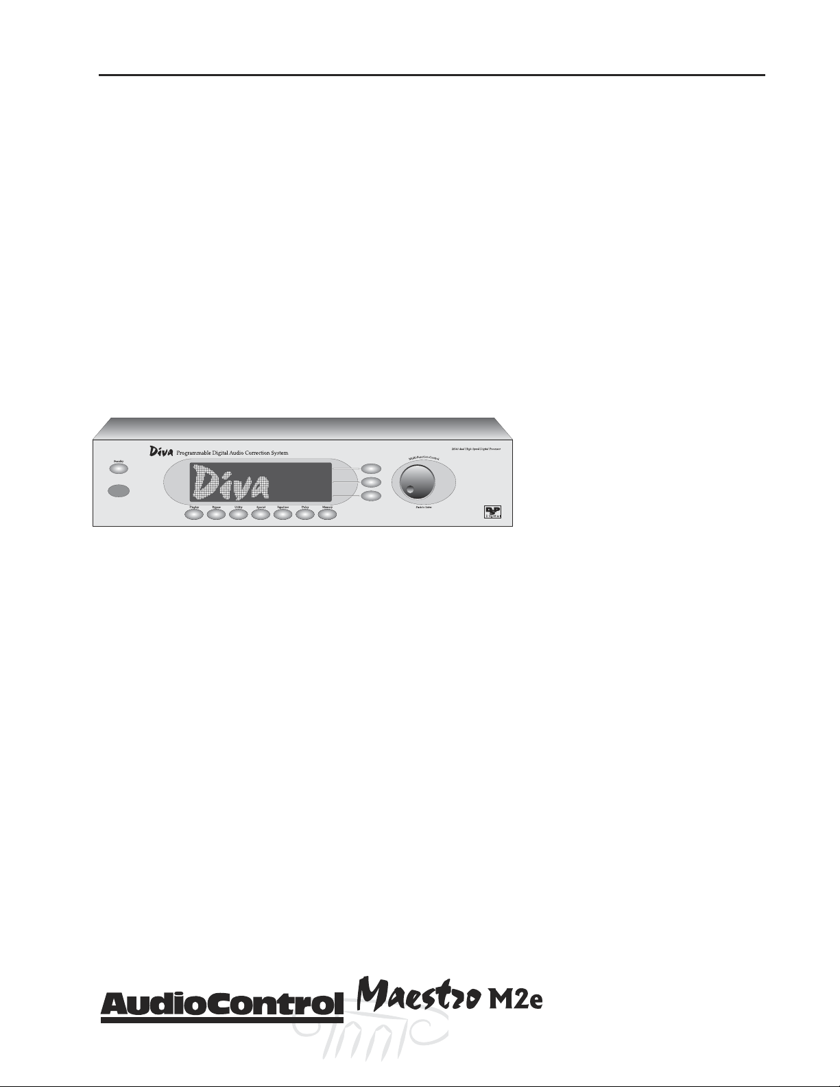
Appendix
Appendix A
Using the Maestro M2e with the Diva Room Correction Processor
While the Maestro M2e is a very powerful surround processor, some things are best left to a specialist. The Diva
24 bit digital room correction processor is the part of the
AudioControl Perfection Home Theater System product line
up designed to take the theaters sound quality up to the
next level. The Diva includes Graphic and Parametric Equalization, Digital Delays with 0.01 mS resolution, Crossover
filtering, and Compressor/Limiter Dynamics control for 8
channels of audio. It also includes 20 user-configured preset
memories and a powerful automation integration protocol
to make this part of any dream system.
The Diva is simple to connect into the Maestro M2e home
theater system. The analog inputs
and outputs enable the Diva to
connect between the preamplifier
outputs of the Maestro M2e and
the inputs of your power amplifiers (preferably the Pantages and
Avalon).
For adjusting the Diva, we highly recommend using the
AudioControl Industrial IasysHT theater analyzer with the
HT-100 switcher. The IasysHT enables extremely precise
one-twelfth audio analysis for treating room acoustic mode
problems. The IasysHT is also very capable with speaker
delay measurements. It will measure delay timings down to
1/8” to ensure the best sound imaging that you have ever
heard from a home theater.
®
Phone 425-775-8461 • Fax 425-778-3166
tm
55
Page 56
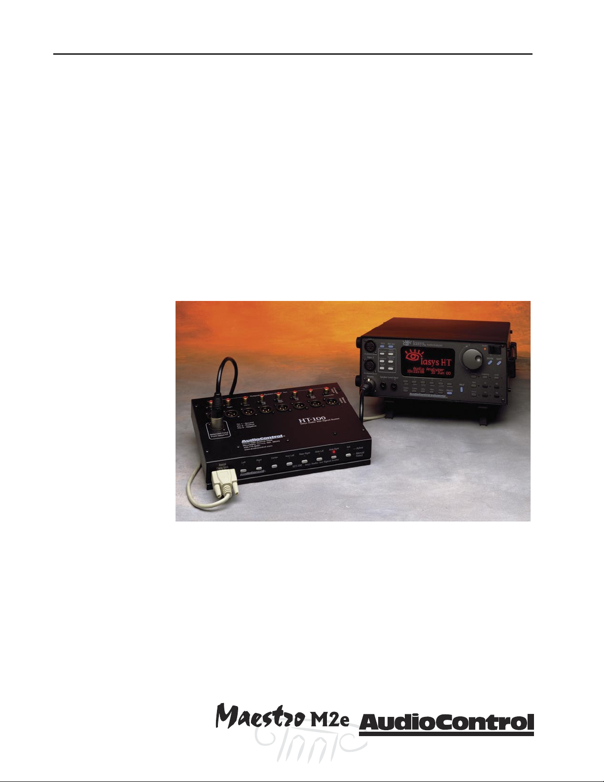
Appendix
Appendix B - Factory Theater Calibration Service
An integral part of the AudioControl Perfection Home
Theater system is the acoustical calibration of the system. Especially in systems where the power of the Diva
room correction processor is used. To help with this task,
AudioControl offers a Factory Theater Calibration Service. A
factory-trained technician using the AudioControl Industrial IasysHT theater analyzer and other tools of the trade,
will come to your theater and ensure that you are getting
the best sound possible from your system.
For more information about this service, contact your
AudioControl sales representative or dealer.
56
tm
®
Phone 425-775-8461 • Fax 425-778-3166
Page 57
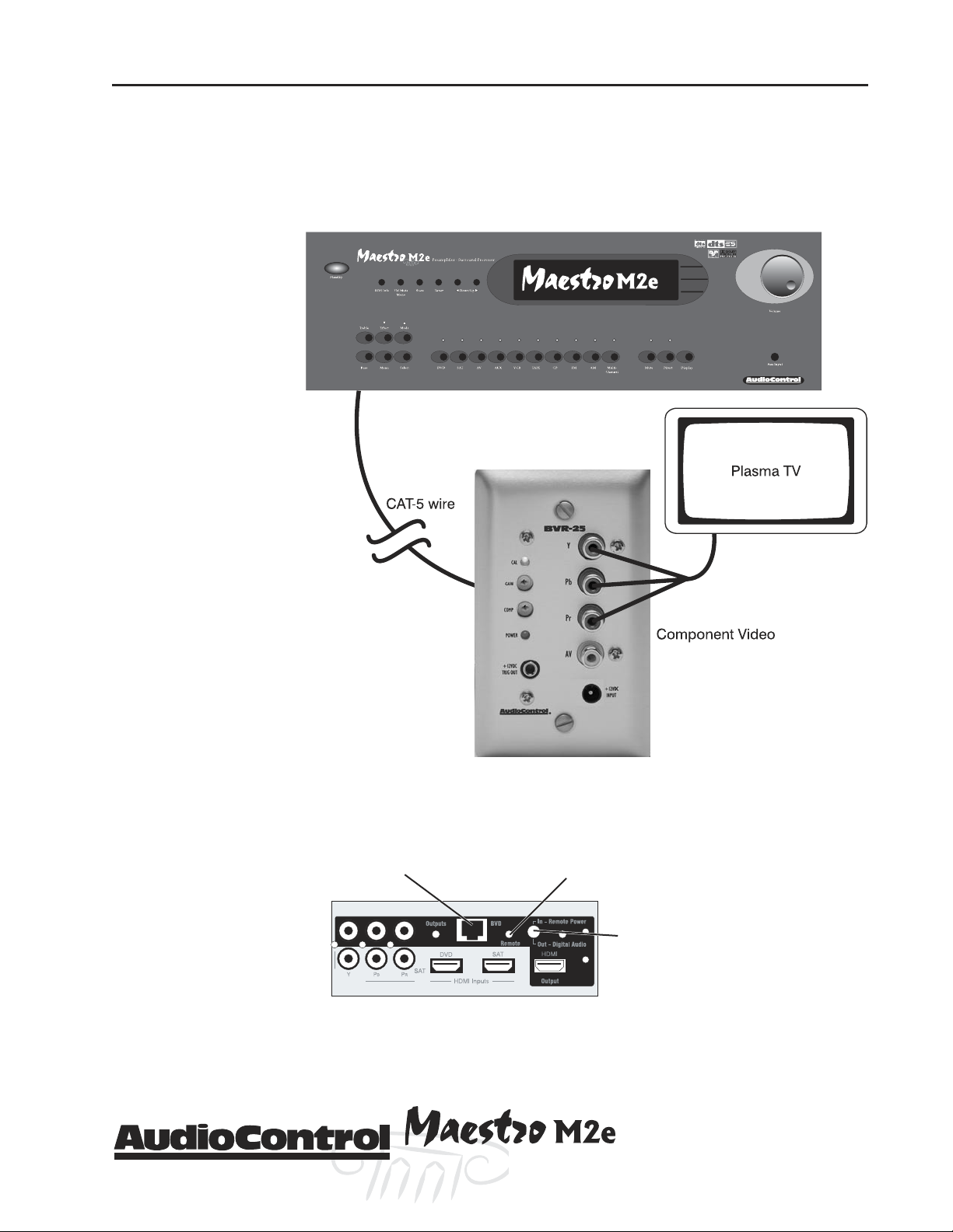
Appendix
Appendix C – Using The Active Balanced Outputs On
Your Maestro M2e
Output to BVR-25
Active Balanced Outputs on Maestro M2e
®
Phone 425-775-8461 • Fax 425-778-3166
LED Indicator
“Red” - Remote Power
“OFF” - Digital Audio
Remote Power/Digital Audio Switch
tm
57
Page 58

Warranty
Warranty
and now a word from the legal department...
People are scared of warranties. Lots of fine print. Months
of waiting around. Well, fear no more. This warranty is
designed to make you rave about us to your friends. It’s a
warranty that looks out for you and helps you resist the
temptation to have your friend, who’s “good with electronics”, try to repair your AudioControl product. So go ahead,
read this warranty, then take a few days to enjoy your new
Maestro M2e home theater system before sending in the
warranty card and comments.
“Conditional” doesn’t mean anything ominous. The Federal
Trade Commission tells all manufacturers to use the term
to indicate that certain conditions have to be met before
they’ll honor the warranty. If you meet all of these conditions, we will warrant all materials and workmanship on
the Maestro M2e for five (5) years from the date you bought
it, and we will fix or replace it, at our option, during that
time.
Here are the conditional conditions:
1. You have to fill out the warranty card and send it to us
within 15 days after purchasing the Maestro M2e.
2. You must keep your sales receipt for proof of purchase
showing when and from whom the unit was bought. We’re
not the only ones who require this, so it’s a good habit to
get into with any major purchase.
3. The Maestro M2e must have originally been purchased
from an authorized AudioControl dealer. You do not have to
be the original owner, but you do need a copy of the original sales receipt or invoice.
4. You cannot let anybody who isn’t: (A) the AudioControl
factory; (B) somebody authorized in writing by
AudioControl to service the Maestro M2e. If anyone other
than (A) or (B) messes with the Maestro M2e, that voids
your warranty.
58
tm
®
Phone 425-775-8461 • Fax 425-778-3166
Page 59

5. The warranty is also void if the serial number is altered
or removed, or if the Maestro M2e has been used improperly. Now that sounds like a big loophole, but here is all we
mean by it:
Unwarranted abuse is: (A) physical damage (don’t use the
Maestro M2e to level your projection TV); (B) improper
connections (120 volts into the RCA jacks can fry the poor
thing); (C) sadistic things. This is the best product we know
how to build, but if you strap it to the front bumper of
your Range Rover, something will break.
Assuming you conform to 1 through 5 (and it really isn’t
all that hard to do) we get the option of fixing your original
unit or replacing it with a new one.
Legalese Section
This is the only warranty given by AudioControl. This warranty gives you specific legal rights that vary from state to
state. Promises of how well the Maestro M2e will perform
are not implied by this warranty. Other than what we have
covered in this warranty, we have no obligation, express or
implied. Also, we will not be obligated for direct or indirect
consequential damage to your system caused by hooking
up or operating the AudioControl Maestro M2e.
Warranty
Failure to send in a properly completed warranty card negates any service claims.
®
Phone 425-775-8461 • Fax 425-778-3166
tm
59
Page 60

What to do if you need service
Normally service will be handled by your AudioControl system professional who installed the system. If you’re the take charge kind of person
who wants to do this yourself, contact AudioControl, either by phone
425/775-8461 or email at [email protected]. We’ll verify if there
is anything wrong that you can fix yourself, or arrange to have it sent
back to our factory for repair. Please include the following items with
the returning unit:
1. A copy of your proof of purchase (that sales receipt we’ve been harping about). No originals please. We cannot guarantee returning them
to you.
2. A brief explanation of the trouble you are having with the Maestro
M2e.
3. A return street address. (No PO Boxes, please)
4. A daytime phone number in case our technician has a question about
the problem you are having.
You’re responsible for the freight charges to us, but we’ll pay the return
freight back. We match whatever shipping method you send it to us, so
if you return the unit overnight freight, we send it back overnight. We
recommend UPS for any shipments.
60
tm
®
Phone 425-775-8461 • Fax 425-778-3166
Page 61
Specifications
Maestro M2e Theater Surround Processor Specifications
Audio
S/N Ratio (unwtd 20Hz/20kHz) – analog . . . . . . . . . . . . . . >100dB
S/N Ratio (unwtd 20Hz/20kHz) – digital . . . . . . . . . . . . . . >100dB
THD - Analog Inputs. . . . . . . . . . . . . . . . . . . . . . . . . . . . . . . 0.003%
THD - Digital Inputs (24 bit) . . . . . . . . . . . . . . . . . . . . . . . . 0.003%
Video
Composite & S-Video Bandwidth . . . . . . . . . . . . . . . . . .>12 MHz
Component Video Bandwidth . . . . . . . . . . . . . . . . . . . . . 150 MHz
HDMI Bandwidth . . . . . . . . . . . . . . . . . . . . . . . . . . . . . . . . . . . . . .
Digital
Coaxial Inputs/Outputs (level / impedance) 3/1 @ 0.5V / 75 ohms
Sampling frequencies. . 44.1 kHz, 48kHz, and 96kHz (stereo only)
S/PDIF Optical Inputs/Outputs . . . . . . . . . . . . . . . . . . . . . . . . . 3/1
Inputs
Analog Audio Inputs. . . . . . . . . . . . . . . . . . . . . . . . . .7 Stereo Pairs
Multi-channel Analog Audio Input . . . . . . . . . . . . . 1 (8 channels)
Digital Audio Inputs . . . . . . . . . . . . . . . . . . . . . . 3 Coax, 3 Optical
Video Inputs . . . . 5 Composite, 5 S-Video, 3 Component, 2 HDMI
Specifications
Outputs
Main Audio Output . . . . . . . . . . . . . . . . . . . . . . . . . . . .8 channels
Second Zone Audio Output . . . . . . . . . . . . . . . . . . . . 1 Stereo Pair
Digital Audio Output . . . . . . . . . . . . . . . . . . . . . 1 Coax, 1 Optical
Main Video Outputs. . . . . . . . . . 1 Composite, 1 Active Balanced,
1 S-Video, 1 Component, 1 HDMI
Second Zone Video Output . . . . . . . . . . . . . . . . . . . . 1 Composite
Control Audio
12 Volt Trigger Output . . . . . . . . . . . . . . . . . . . . . .1 Main, 1 Video
RS-232 Serial Control . . . . . . . . . . . . . . . . . . . . . . . . . . . . .1 - DB-9
IR Receiver Input - Main . . . . . . . . . . . . . . . .1 - 3.5 mm Minijack
IR Receiver Input - Zone 2 . . . . . . . . . . . . . . . 1 - 3.5 mm Minijack
IR Emitter Output . . . . . . . . . . . . . . . . . . . . .1 - 3.5 mm Minijack
General
Power Consumption. . . . . . . . . . . . . . . . . . . . . . . . . . . . . 35 Watts
Dimensions . . . . . . . . . . . . . . . . . . . . . . . 17”W x 15.5”D x 5.25”H
Weight . . . . . . . . . . . . . . . . . . . . . . . . . . . . . . . . . . . . . . . . . . .30 lbs
®
Phone 425-775-8461 • Fax 425-778-3166
tm
61
Page 62
For Those Who Consider Perfection Possible
22410 70th Avenue West
Mountlake Terrace, WA 98043 USA
425-775-8461 • Fax 425-778-3166
www.AudioControl.com
P/N 913-090-0
®
®
 Loading...