

AudioControl 7.1 Channel THX Ultra 2 Theater Processor, Maestro 7.1 Channel THX Ultra 2 Theater Processor User Manual

Home Theater
SYSTEM
Maestrotm
7.1 Channel THX Ultra 2 Theater Processor
For those who consider
perfection possible
©2003. All Rights Reserved
SM
22410 70th Avenue West Mountlake Terrace, WA 98043 USA
Phone 425-775-8461 Fax 425-778-3166
www.audiocontrol.com
®


Maestrotm
7.1 Channel THX Ultra 2 Theater Processor
For those who consider
perfection possible
©2003. All Rights Reserved
22410 70th Avenue West Mountlake Terrace, WA 98043 USA
Phone 425-775-8461 Fax 425-778-3166
www.audiocontrol.com
SM
®

Maestro
tm
Phone 425-775-8461 • Fax 425-778-3166
®

Owners Manual – Maestro 7.1 Theater Processor
Table of Contents
Prelude
AudioControl Home Theater System Features . . . . . . . . . . . . 1-1
Front Panel Features . . . . . . . . . . . . . . . . . . . . . . . . . . . . . . . . . 1-2
Rear Panel Features . . . . . . . . . . . . . . . . . . . . . . . . . . . . . . . . . . 1-3
Installation
System Configuration Questionnaire . . . . . . . . . . . . . . . . . . . 2-1
Connection Tips . . . . . . . . . . . . . . . . . . . . . . . . . . . . . . . . . . . . 2-3
Unit Placement . . . . . . . . . . . . . . . . . . . . . . . . . . . . . . . . . . . . 2-3
Speaker Considerations and Placement . . . . . . . . . . . . . . . . . 2-4
Power . . . . . . . . . . . . . . . . . . . . . . . . . . . . . . . . . . . . . . . . . 2-5
Audio Connections . . . . . . . . . . . . . . . . . . . . . . . . . . . . . . . . . 2-5
Multi-Channel Analog Audio . . . . . . . . . . . . . . . . . . . . . . . . . 2-5
Choosing your video . . . . . . . . . . . . . . . . . . . . . . . . . . . . . . . . 2-7
Input Configuration . . . . . . . . . . . . . . . . . . . . . . . . . . . . . . . . 2-7
IR Remote Control Connections . . . . . . . . . . . . . . . . . . . . . . . 2-8
12V Trigger Connections . . . . . . . . . . . . . . . . . . . . . . . . . . . . . 2-8
Second Zone Connections . . . . . . . . . . . . . . . . . . . . . . . . . . . . 2-9
Configuration
Entering the Setup Mode . . . . . . . . . . . . . . . . . . . . . . . . . . . . 3-1
Configuration Settings Menu Lock . . . . . . . . . . . . . . . . . . . . . 3-1
Navigating the Menus . . . . . . . . . . . . . . . . . . . . . . . . . . . . . . . 3-1
Using Presets . . . . . . . . . . . . . . . . . . . . . . . . . . . . . . . . . . . . . . 3-2
Level Settings . . . . . . . . . . . . . . . . . . . . . . . . . . . . . . . . . . . . . . 3-6
Subwoofer Settings . . . . . . . . . . . . . . . . . . . . . . . . . . . . . . . . . 3-6
THX Settings . . . . . . . . . . . . . . . . . . . . . . . . . . . . . . . . . . . . . . 3-7
ADV 1 – Speaker Equalization . . . . . . . . . . . . . . . . . . . . . . . . . 3-8
ADV 2 – Video Settings . . . . . . . . . . . . . . . . . . . . . . . . . . . . . . . 3-8
ADV 3 – Digital Settings . . . . . . . . . . . . . . . . . . . . . . . . . . . . . . 3-9
ADV 4 – Zone 2 Settings . . . . . . . . . . . . . . . . . . . . . . . . . . . . . 3-9
ADV 5 – Input Trims . . . . . . . . . . . . . . . . . . . . . . . . . . . . . . . . 3-10
Table of Contents
©2003. All Rights Reserved.
Phone 425-775-8461 • Fax 425-778-3166
Maestro
®
tm
i

ii
Maestro
tm
Phone 425-775-8461 • Fax 425-778-3166
®

Using the Maestro
Main Zone . . . . . . . . . . . . . . . . . . . . . . . . . . . . . . . . . . . . . . . . 4-1
Turning the Maestro On . . . . . . . . . . . . . . . . . . . . . . . . . . . . . 4-1
Using the Main Menus . . . . . . . . . . . . . . . . . . . . . . . . . . . . . . 4-1
Simulcast Listening . . . . . . . . . . . . . . . . . . . . . . . . . . . . . . . . . 4-4
VCR and Tape Operation . . . . . . . . . . . . . . . . . . . . . . . . . . . . . 4-5
Stereo Direct . . . . . . . . . . . . . . . . . . . . . . . . . . . . . . . . . . . . . . . 4-5
Setting the Surround Modes . . . . . . . . . . . . . . . . . . . . . . . . . . 4-5
THX Mode . . . . . . . . . . . . . . . . . . . . . . . . . . . . . . . . . . . . . . . . 4-6
DSP Effects . . . . . . . . . . . . . . . . . . . . . . . . . . . . . . . . . . . . . . . . 4-6
Display Brightness . . . . . . . . . . . . . . . . . . . . . . . . . . . . . . . . . . 4-6
Second Zone . . . . . . . . . . . . . . . . . . . . . . . . . . . . . . . . . . . . . . 4-7
Integration with Automation
Introduction . . . . . . . . . . . . . . . . . . . . . . . . . . . . . . . . . . . . . . 5-1
RS-232-Serial . . . . . . . . . . . . . . . . . . . . . . . . . . . . . . . . . . . . . . 5-2
Table of Contents
Surround Modes
Selecting Surround Modes . . . . . . . . . . . . . . . . . . . . . . . . . . . 6-1
®
Modes . . . . . . . . . . . . . . . . . . . . . . . . . . . . . . . . . . . . . . . 6-4
THX
About THX Cinema Processing . . . . . . . . . . . . . . . . . . . . . . . . 6-2
Effects Modes . . . . . . . . . . . . . . . . . . . . . . . . . . . . . . . . . . . . . . 6-6
Troubleshooting
General . . . . . . . . . . . . . . . . . . . . . . . . . . . . . . . . . . . . . . . . . 7-1
Video . . . . . . . . . . . . . . . . . . . . . . . . . . . . . . . . . . . . . . . . . 7-1
Audio . . . . . . . . . . . . . . . . . . . . . . . . . . . . . . . . . . . . . . . . . 7-2
Appendicies
Appendix A – Menu Tree . . . . . . . . . . . . . . . . . . . . . . . . . . . . . 8-1
Appendix B – Using the Maestro
with the Diva Room Correction Processor . . . . . . . . . . . . 8-4
Appendix C – RS-232 Serial Control Protocol Commands . . . 8-5
Appendix D – IR Remote Control Codes . . . . . . . . . . . . . . . . 8-10
Appendix E - Factory Theater Calibration Service . . . . . . . . . 8-11
Appendix F – Updating the Maestro . . . . . . . . . . . . . . . . . . . 8-11
Warranty
Warranty . . . . . . . . . . . . . . . . . . . . . . . . . . . . . . . . . . . . . . . . . 9-1
What to do if you need service . . . . . . . . . . . . . . . . . . . . . . . . 9-2
Specifications
Maestro Theater Surround Processor Specifications . . . . . . 10-1
Phone 425-775-8461 • Fax 425-778-3166
Maestro
®
tm
iii

7.1 Plus Theater System
iv
Maestro
tm
Phone 425-775-8461 • Fax 425-778-3166
®

Congratulations
Great attention to system design and installation makes the difference
between an average multiplex theatre and a great movie palace. When
creating your own personal movie palace experience, the choice of
components is just as critical. AudioControl knows how important the
right equipment is and for that reason we created our Home Theater
System.
This new digital audio surround system is made by the only consumer
electronics company in the world that specializes in making good
sound better. AudioControl’s passion for high quality, meticulous
attention to detail and pro sound heritage shows itself in the dozens of
awards we have won for our designs, products and service.
This manual is designed to help you get the most from the Maestro.
So, even though you’re dying to plug it in and start pushing buttons,
please take thirty minutes or so to glance over this tome and learn
about the Maestro 7.1 channel theater surround processor. Any component that does as much as the Maestro does deserves all the explanation it can get.
Most Important Instruction of All
Make certain the warranty card is filled out and mailed back to us.
Also, record the serial number and put your sales receipt or invoice in a
safe place. This is very important in the unlikely event that the Maestro
gets a sudden illness, or for proof of ownership if somebody takes a
fancy to your theater system in the middle of the night. Insurance
companies have no imagination when it comes to components like the
Maestro being part of the theater system. This concludes the nagging
section of this manual.
Phone 425-775-8461 • Fax 425-778-3166
Maestro
®
tm
v

vi
Maestro
tm
Phone 425-775-8461 • Fax 425-778-3166
®

Key Features
AudioControl Home Theater System
The Maestro is part of the AudioControl Home Theater System. Also included in this system are the Diva Digital Room Correction Processor, the
Avalon and Pantages High Definition Amplifiers and the Factory Certified
System Calibration. Together these components ensure superior audio and
video performance from your home theater system.
Multiple Surround Sound Formats
The powerful dual 24 bit DSP processors enable the Maestro to decode all
current consumer 5.1, 6.1 and 7.1 channel THX, Dolby and DTS surround
formats. The flash memory allows the Maestro to be upgraded in the
future when new formats become available.
Broadcast Quality Video Routing
Great sound is important, but you need a great picture also to complete a
super home theater. All video routing in the Maestro has it’s roots in
broadcast studio. With 300 MHz of video bandwidth you will see even the
finest details from the video sources even with demanding 1080i and
current progressive scan HDTV signals.
THX Ultra 2 Certified
Lucasfilm sets the standards of performance for THX certified components.
Before any home theater component can carry the THX Ultra 2 logo, it
must pass a demanding set of quality and performance tests. The THX
Ultra 2 certification ensures that you will receive superior performance
from this equipment for years to come.
Features
Extensive Automation Integration
A touch screen or automation system is what really pulls a high-end home
theater together. It puts the full power of the system at your fingertips.
The RS-232 serial port and infrared remote control inputs feature an
extensive command library to control all aspects of the Maestro. You have
the power.
Non-Volatile Configuration Presets
With five configuration presets, it is simple to quickly recall your favorite
combinations of Input Source, Surround Processing Mode, Delays and DSP
Effects. With one command, the Maestro jumps into action and makes all
the changes that would normally take multiple button presses and menus.
These presets are stored in Flash memory so they won’t be lost when the
power goes out.
Second Zone Outputs
Do you want to enjoy your home theater system in the bedroom also? The
Second Zone output of the Maestro enables you to independently control
the source selection and volume to a room outside of the home theater.
Award-Winning Quality
A product of AudioControl – an award winning manufacturer of highquality audio components since 1977. This product line is backed up with
a comprehensive Five-Year warranty.
Phone 425-775-8461 • Fax 425-778-3166
Maestro
®
tm
Section 1-1
The Cast
ux
w
y
v
z
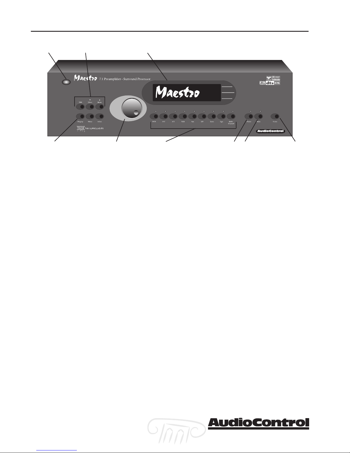
Front Panel Features
IR Remote Control Sensor –IR Remote Control Sensor –
u
IR Remote Control Sensor – Behind this
IR Remote Control Sensor –IR Remote Control Sensor –
window is the infrared sensor remote control.
If the Maestro is located in a system where
this window is not line-of-sight with the main
listening seat; a rear panel jack enables use of
an outboard IR sensor.
Fluorescent Control Display –Fluorescent Control Display –
v
Fluorescent Control Display – With the
Fluorescent Control Display –Fluorescent Control Display –
easy to follow menus, it is simple to operate
and configure the Maestro.
Display Brightness Select –Display Brightness Select –
w
Display Brightness Select – This button
Display Brightness Select –Display Brightness Select –
toggles the display between two brightness
levels or completely turns the display off. This
is nice to get rid of distractions while you’re
watching a good movie.
Menu Control Buttons –Menu Control Buttons –
x
Menu Control Buttons – These buttons
Menu Control Buttons –Menu Control Buttons –
control the surround mode, DSP effects and
are used for the setup menus.
Multifunction Control Knob –Multifunction Control Knob –
y
Multifunction Control Knob – In normal
Multifunction Control Knob –Multifunction Control Knob –
use, this knob is the volume control. When in
the setup menus, turn this knob to select
menus and options.
Source Selection Buttons –Source Selection Buttons –
z
Source Selection Buttons – Simple enough,
Source Selection Buttons –Source Selection Buttons –
just press a button to choose what you want
|
{
to watch or listen to. (The menu button enables you to listen to a different source than
you are watching. Refer to page 4-1 for more
information.)
Stereo Direct –Stereo Direct –
{
Stereo Direct – This button defeats all
Stereo Direct –Stereo Direct –
digital signal processing and directs the twochannel analog input from the selected source
to the front outputs. Use this button when
you want to do some serious quality listening.
Mute –Mute –
|
Mute – Need to answer the phone, but still
Mute –Mute –
keep an eye on the TV? Just press the Mute
button to turn off the sound. Press it again
and the audio gracefully ramps back up to
where you were so rudely interrupted.
Main PMain P
}
Main P
Main PMain P
switch. You should only need to turn off the
Maestro with this button when the system
will not be used for some time. Normally this
button is left on and the Maestro is put into
“Standby Mode” by the controller or automation system. When the main power button is
turned off, you cannot turn the Maestro on
with the Infrared or RS-232 inputs.
ower –ower –
ower – Think of this as the vacation
ower –ower –
}
Section1-2
Maestro
tm
Phone 425-775-8461 • Fax 425-778-3166
®
The Cast
x
z
|
u
v
w
y
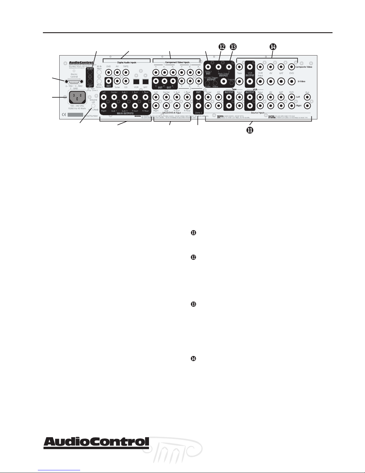
Rear Panel Features
RS232 Serial PRS232 Serial P
u
RS232 Serial P
RS232 Serial PRS232 Serial P
interface the Maestro with an external touchscreen or other automation system. It is also used
when updating the internal Maestro firmware
programming.
Main PMain P
v
Main P
Main PMain P
flows in here. The wide-range switching power
supply enables the Maestro to operate at full
capacity even during brown-outs.
Ground Lift Switch –Ground Lift Switch –
w
Ground Lift Switch – In complex home theater
Ground Lift Switch –Ground Lift Switch –
systems, ground loops can be a painful fact of life.
This button isolates the signal ground connections on the Maestro from the AC Power ground.
For safety reasons, the chassis remains earth
grounded at all times.
IR Remote Control Connections –IR Remote Control Connections –
x
IR Remote Control Connections – These jacks
IR Remote Control Connections –IR Remote Control Connections –
enable use of external IR sensors and emitters for
installations where it is not practical to use the
front panel IR sensor.
Main Amplifier Outputs –Main Amplifier Outputs –
y
Main Amplifier Outputs – The RCA outputs
Main Amplifier Outputs –Main Amplifier Outputs –
feed the main theater power amplifiers.
Digital ADigital A
z
Digital A
Digital ADigital A
features assignable Coaxial and Optical digital
audio inputs. Don’t worry if your satellite has a
Coaxial digital output but the SAT connection on
the back of the Maestro is Optical: You can reassign the connection.
Multi-Multi-
{
Multi-
Multi-Multimulti-channel audiophile recordings give you
superb music audio quality in full surround.
These players feature a surround decoder built
into them. The Multi-channel inputs on the
Maestro bypass all digital circuitry and connect
the player to the amplifiers with only a volume
control in the path. Enjoy!
ower Connection –ower Connection –
ower Connection – All good AC power
ower Connection –ower Connection –
Channel DChannel D
Channel D
Channel DChannel D
ort – ort –
ort – This connection is used to
ort – ort –
udio Connections – udio Connections –
udio Connections – The Maestro
udio Connections – udio Connections –
VDVD
--
VD
VDVD
A / SAA / SA
-
A / SA
--
A / SAA / SA
CD Input –CD Input –
CD Input – Newer
CD Input –CD Input –
{
~
}
Component VComponent V
|
Component V
Component VComponent V
video is one of the highest quality formats available. Use them whenever possible.
Zone 2 AZone 2 A
}
Zone 2 A
Zone 2 AZone 2 A
puts enables listening to a source independently of
the main theater system.
Zone 2 VZone 2 V
~
Zone 2 V
Zone 2 VZone 2 V
video output for zone 2. You must connect the
composite video input from each source unit to
make them available for this second zone output.
Stereo Analog AStereo Analog A
Stereo Analog A
Stereo Analog AStereo Analog A
the two channel stereo outputs from your source
units here.
12 V12 V
olt Tolt T
12 V
olt T
12 V12 V
olt Tolt T
a +12 volt signal to control the power amplifiers,
source units, video projector, screens and curtains
in the theater. The Main Trigger output is active
whenever the Maestro is turned on; the Video
Trigger is active whenever a video source is selected.
Main VMain V
Main V
Main VMain V
and S-Video outputs to the main video display or
projector. Since we know that converting between
video formats is something best left to an external
video processor, you should always connect the
Composite, S-Video and the Component video
outputs to your video display or processor.
Composite and S-Composite and S-
Composite and S-
Composite and S-Composite and Sare the video inputs from the source units. If you
are using the second zone video outputs, you
should ALWAYS connect a composite video input
from each source even if you are using a higher
quality S-Video or Component signal for the main
theater. These inputs are assignable so if your CD
player has a video output and your tape deck
doesn’t, you can rearrange the inputs. Refer to page
3-8 for details.
ideo Outputs –ideo Outputs –
ideo Outputs – These are the Composite
ideo Outputs –ideo Outputs –
ideo Connections –ideo Connections –
ideo Connections – Component
ideo Connections –ideo Connections –
udio Output – udio Output –
udio Output – The second zone out-
udio Output – udio Output –
ideo Output – ideo Output –
ideo Output – This is the composite
ideo Output – ideo Output –
udio Connections –udio Connections –
udio Connections – Connect
udio Connections –udio Connections –
rigger Outputs – rigger Outputs –
rigger Outputs – These outputs provide
rigger Outputs – rigger Outputs –
VV
ideo Connections – ideo Connections –
V
ideo Connections – These
VV
ideo Connections – ideo Connections –
Phone 425-775-8461 • Fax 425-778-3166
Maestro
®
tm
Section1-3

Features
Section 1-4
Maestro
tm
Phone 425-775-8461 • Fax 425-778-3166
®

Installing the Maestro
System Configuration Questionnaire
Before you begin the system installation, there are a few
things to think about. Please fill in the blanks and answer
some questions to help make this process go easier. The
appropriate section of the manual is referred to after each
question to properly configure the Maestro.
Installation
Source Units
Input Source Unit Digital Input Component Video Input
Tuner
CD
Tape
VCR
A/V
Sat
DVD
Aux
– Fill in the blanks
example: Tuner None Tape
Refer to Page 3-8 For assigning the Component Video
Inputs
Refer to Page 3-9 For assigning the Digital Audio Inputs
Speakers – Check description that best fits the speakers
Channel Large (Full Range) Small (No Bass)
Left/Right
Center
Surround (side)
Rear
Phone 425-775-8461 • Fax 425-778-3166
Are the Rear Speakers further than 48” apart? No / Yes
+
Refer to Page 3-5 For Setting the Speaker Sizes
Refer to Page 3-7 For THX Rear Speaker Array Settings
Maestro
®
tm
Section 2-1

Installation
How Many Subwoofers? (Circle one) 1 2 3
+
Are the Subwoofers THX Certified? No / Yes / THX Ultra 2
+
Refer to Page 3-6 For Subwoofer Settings
Refer to Page 3-7 For THX Subwoofer Settings
Do you need remote 12 volt triggers for the Amplifiers or
+
Video Projector? No / Yes
Refer to Page 2-8 For using the remote trigger outputs
Will you be controlling the Maestro with IR remote
+
control? No / Yes
Refer to the Home Theater System CD for CCF files of the IR
codes
or… Use the AudioControl MX-500 Theater System Remote
(optional)
Will you be controlling the Maestro with RS232 Serial
+
Control? No / Yes
Refer to Page 8-5 For using the RS-232 Serial control
protocol
Refer to the Home Theater System CD for the serial proto-
col specifications
Do you want the ultimate performance from this system?
+
No / Yes
Refer to the entire AudioControl Home Theater System
product line and the factory calibration services available.
Section 2-2
Maestro
tm
Phone 425-775-8461 • Fax 425-778-3166
®

Planning your installation
Connection Tips
Even if you’re an electronics veteran, this part may seem
repetitive, but some things can never be repeated too
many times.
• Don’t stand in a bucket of water when working with
electricity.
• Turn off all components before making any connections.
• When making connections, make sure that “left goes to
left” and “right goes to right.” The obvious and timehonored way to assure this is to assign RED plugs to
Right and WHITE/GREY/BLACK plugs to the left. Yellow is
usually used for video cables or digital audio connections.
• Wherever possible, keep power cords away from signal
cables (i.e., inputs from disk players, VCRs, etc.) to prevent induced hum. Bundle all power cords down one
side of your equipment cabinet and all the signal cables
down the other.
Installation
• Use high quality interconnect cables. We’re not going to
get into the debate about whether $100 per meter interconnects improve the sound and picture quality of your
system. We do know from experience however that
really, REALLY cheap connections can cause problems.
They tend to corrode, oxidize, and disconnect inside;
causing a hum or loss of signal. This not only degrades
the sound quality, but it will also lead to call-backs to
repair the system later.
Unit Placement
We know you’ve heard all of this before, but here goes…
The Maestro can be placed almost anywhere in your audio
equipment stack. This unit will generate a small amount of
heat during normal operation. Ensure that the equipment
location is properly ventilated. Make certain not to block
the ventilation slots on any other component. Also, avoid
placing Maestro directly over a large power amplifier. These
amps can get pretty hot and have big power transformers
that can induce hum into other audio components like
Maestro. Make certain that there is an unobstructed lineof-sight between the location where the remote controller
sits and the Maestro front panel.
Phone 425-775-8461 • Fax 425-778-3166
Maestro
®
tm
Section 2-3
Installation
Remember to consider the user when installing the Maestro
in a rack. If the primary operator is taller than average you
may want to put the Maestro and source units higher in the
rack so they can see their front panels. The same rule applies
on the shorter side. Remember, the person designing and
installing the system isn’t always the person who will be
using it on a daily basis.
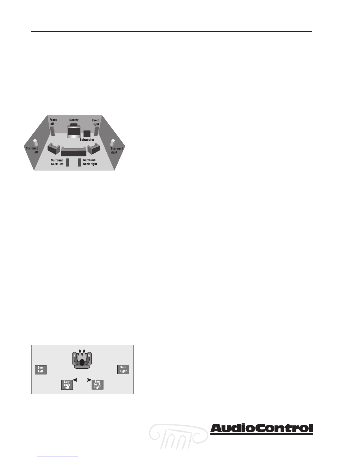
Speaker Considerations and Placement
Choosing the right speakers and putting them in the correct
positions is crucial to getting the most out of a home theater
system. For the full THX surround EX playback experience,
we recommend choosing a THX certified speaker system.
Once you have decided on the speakers you are using, make
certain the Maestro is configured to match your speakers.
Front LCR (Left, Center, Right) Speakers
To present the most realistic soundstage, all three of the front
speakers must be tonally balanced. Ideally, these speakers
should be identical models. This ensures that the sound
doesn’t change as it pans across the screen. Place the speakers
at the seated ear level. Whenever possible, the three front
speakers should also be placed at the same horizontal level
for best imaging.
Side Surround Speakers
The surround speakers provide the reverberant, or ambient,
sound effects in a multi-channel theater audio system. These
speakers should be placed on the side walls approximately
36” above the seated ear height of the listeners. If you are
using surround speakers which have a dipole sound pattern
they should be mounted in-line with the main seating
position. If the surrounds are direct radiator, they should be
just behind the main listening seat.
Rear (Back) Surround Speakers
These channels are used in 7.1 mode systems to provide
extra depth in the soundfield. These speakers should be
placed approximately 36” above the seated ear height of the
listeners. These speakers should be mounted close together
(12” to 48” apart) on the rear wall of the theater facing the
screen. If you must place the speakers further apart, make
certain to change the Advanced Speaker Array setting in
the THX Setup Menu to maintain the optimum surround
sound effect.
Section 2-4
Maestro
tm
Phone 425-775-8461 • Fax 425-778-3166
®

Subwoofer
The subwoofer is a large speaker that provides the bottom
end “kick” in the system. THX certified subwoofers are
rated by the cubic volume of the room. Make certain you
remember to include all spaces that open to the theater in
that volume calculation. Depending on the size of your
space, you may require more than one subwoofer to get
the bass volume levels that you desire.
Power
Like many of today’s intelligent home electronics, the
Maestro should be plugged into an unswitched AC outlet
so that it always has power. This allows the RS-232 and
remote control features to work even when the Maestro is
in standby. We always recommend the use a high quality
surge protection device to keep all of your electronics safe
from the evils of public power systems.
Audio Connections
Most of the sources will have two audio connections to the
Maestro; the 2 channel analog audio and the multi-channel digital audio. When given the option, you should
connect both of these audio signals to the Maestro. This
will provide the digital audio signal necessary for highquality digital surround sound along with the analog
audio for tape recording and the second zone audio
output.
Installation
Don’t worry if your satellite receiver has a coaxial digital
output and the Maestro SAT input is optical. Refer to the
advanced configuration section on page 3-9 of this manual
for more information regarding assigning a digital input to
the optical or coaxial connection.
Multi-Channel Analog Audio
Newer audiophile surround recording formats such as
SACD and DVD-A decode the multi-channel signals directly
within the player. The Maestro features an 8 channel direct
analog input for these sources. These inputs bypass the
digital circuitry in the Maestro and route directly to the
Main Amplifier outputs via its own volume control circuit.
This ensures the highest possible audio quality for this
input.
Maestro
®
Phone 425-775-8461 • Fax 425-778-3166
tm
Section 2-5
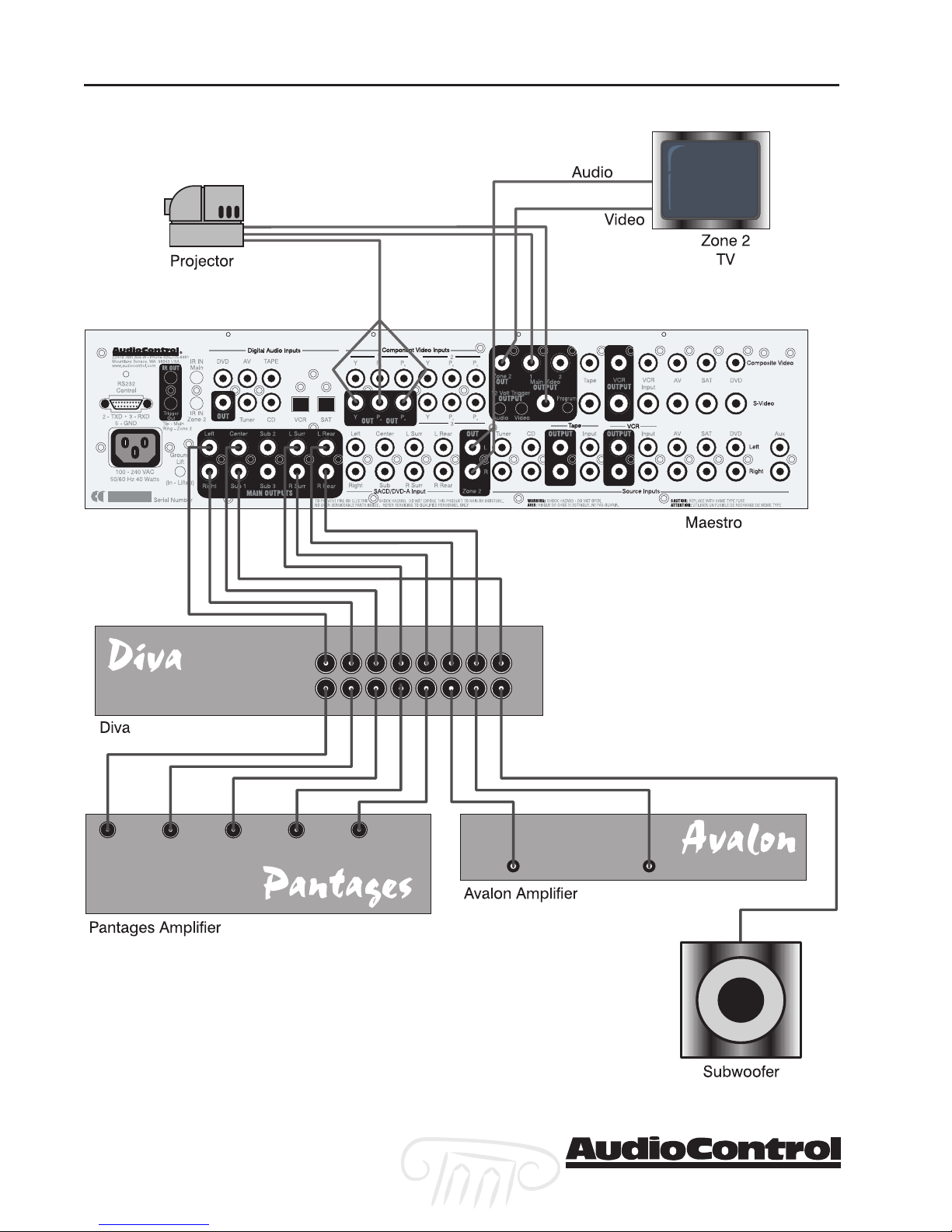
Installation
7.1 Theater System with Second Zone
Section 2-6
Maestro
tm
Phone 425-775-8461 • Fax 425-778-3166
®
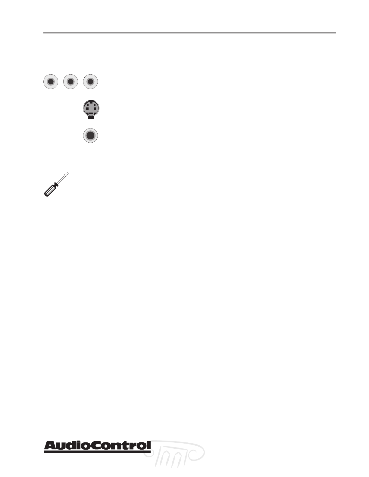
Video Connections
Choosing your video
Component
Y PB P
Important Installation Note:Important Installation Note:
Important Installation Note: If
Important Installation Note:Important Installation Note:
you plan on using the second zone
feature of the Maestro, you will have to
connect Composite video for a source in
addition to whichever higher quality video
connection you choose.
R
S-Video
Composite
Video Connections
Installation
There are three video signal connection formats ranging
from Composite (Good), S-Video (Better) and Component
(Best). Depending on the particular source unit you may
have the option of more than one of these video connections. Always choose the highest quality video output
available on your sources. These are not the same as the
signal connection format with the video format (i.e. 480i,
480p, HDTV), so please don’t confuse them.
Because of the higher bandwidths involved with video
signals, the quality of the interconnect cables you choose
is more critical than the audio cables. Video connections
should always be made with cables specifically designed
for video. Don’t be tempted to grab some extra audio RCA
cables laying around. Without the proper 75 ohm coaxial
cabling, your picture quality will suffer from smear, ghosting or noise. It is always a good idea to make certain that
the video and audio signal cables are routed away from
any power wiring.
Video Conversion
High quality conversion between the various video signal
connection formats is a tricky thing and best left to dedicated video processors. This is why the Maestro doesn’t do
this conversion. If a source input is S-Video, the Maestro
will output S-Video to the monitor or projector. You will
usually need to run all three (Composite, S-video, and
Component) main video outputs of the Maestro to your
video scaler or monitor.
Input Configuration
The component video inputs are fully assignable to the
sources. This allows you to configure the Maestro to look
for the video input from a particular source unit on one of
the three component video inputs. Refer to the Configuration section of this manual on page 3-8 for more information regarding this feature.
Phone 425-775-8461 • Fax 425-778-3166
Maestro
®
tm
Section 2-7
Installation
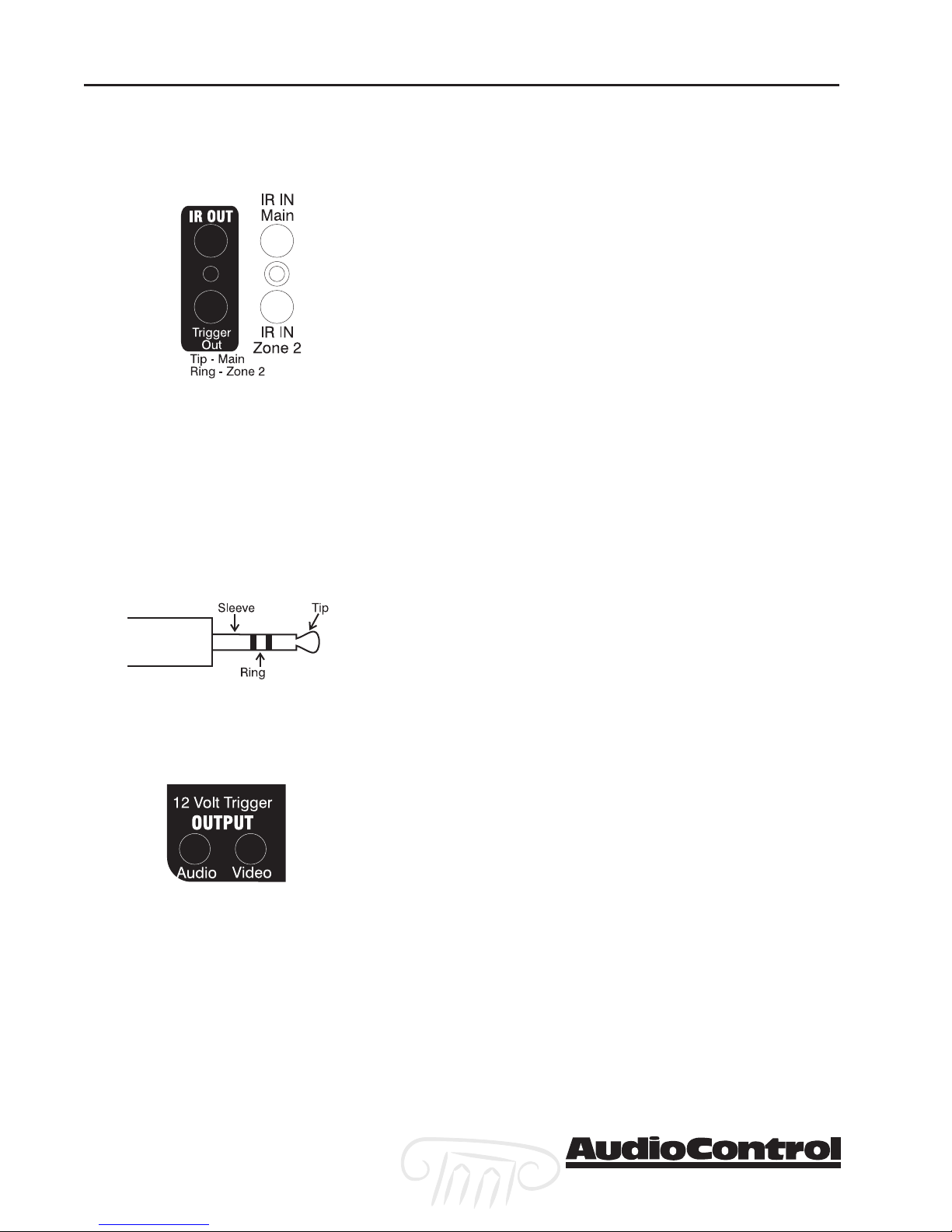
IR Remote Control Connections
Since the Maestro is often hidden away in some dark
closet or equipment rack, we have provided connections
for external IR remote control receivers and emitters. This
allows you to place the infrared receiver where it can “see”
the signal from the remote control. The Zone 2 IR input
controls the second zone functions of the Maestro and also
repeats commands to the source units through the emitter
output.
The IR receiver input connections are wired with a 3
conductor 3.5mm jack. The signals are compatible with
third-party receivers such as a Xantech No. 291-10.
AudioControl does not supply the IR receivers or emitters
to use with the Maestro.
Tip IR Signal
Ring Ground
Sleeve Current Limited +12 VDC (30 mA max.)
1/8” Mini Jack wiring
12V Trigger Connections
There are three mini-jack 12 volt trigger outputs on the
rear panel of the Maestro. These are used to remotely
control such things as the power amplifier turn-on, projector power, screens or curtains. The System Trigger Jack has
two separate outputs. The jack is a three conductor; Tip,
Ring, Sleeve, connection.
Tip Main Zone On
Ring Second Zone On
Sleeve Ground
The other two trigger outputs carry one signal each. The
Main Trigger connection has 12 volts DC when the Maestro
is turned on. The Video Trigger jack goes to 12 volts when
one of the video sources is selected.
Tip +12 VDC
Sleeve Ground
The Main Trigger would generally be used to control the
power to the amplifiers and source units. The Video Trigger
would be used to control the projector or video screen.
Section 2-8
Maestro
tm
Phone 425-775-8461 • Fax 425-778-3166
®
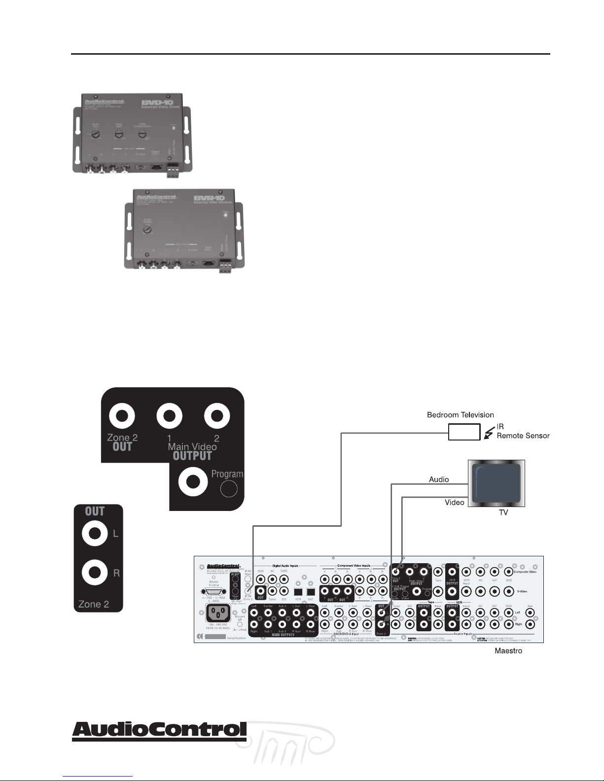
Second Zone Connections
Plug for other AudioControl products: The
Active-Balanced Series products from
AudioControl enables sending high-quality
audio and video signals over standard Category
5 or better twisted pair wiring. Great for getting
the second zone outputs of the Maestro across
the house to your bedroom.
Installation
The Zone 2 outputs on the Maestro enable sending an
independent audio and video signal to a second room,
such as a bedroom. There is a 2 channel stereo analog
audio output and a composite video output.
There is also an IR sensor input for the second zone. This
enables you to remotely control the Maestro and also
repeats the IR to your source units through the IR Output
jack on the Maestro. Any IR signal received through the
Maestro’s front panel IR sensor or through an IR sensor
connected to the IR inputs is repeated to the IR Output for
controlling the source components in your system.
Since the Zone 2 outputs of the Maestro are 2 channel
analog audio and composite video, you must have these
signals connected from your source units to make them
available. The Maestro does not convert a digital audio
signal into analog for zone 2.
Connecting the Second Zone
Phone 425-775-8461 • Fax 425-778-3166
Maestro
®
tm
Section 2-9

Installation
Section 2-10
Maestro
tm
Phone 425-775-8461 • Fax 425-778-3166
®
 Loading...