

Page 1
Features
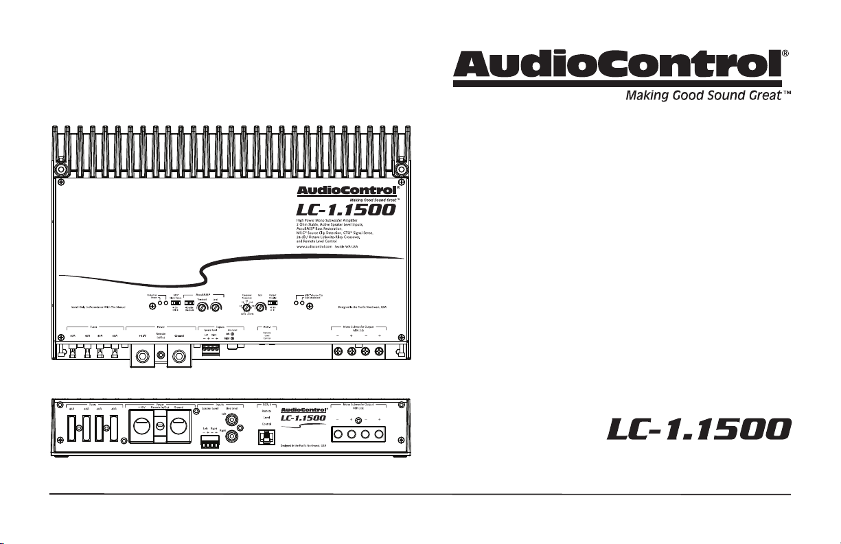
• High Power Mono Subwoofer Amplier
• High Current Design
• 1500 Watts @ 2 Ohm
• MILC™ Maximum Input Level Control (Patent Pending)
• 24 dB/Octave Linkwitz-Riley Alignment Crossover
• GTO Signal Sense
• PFM Subsonic Filter
• Line-Level RCA Inputs and Active Speaker-Level Inputs
• Solid One-Piece Aluminum Chassis
• Optional wired ACR-1 Remote Control for Subwoofer Level
• AccuBASS® Bass Restoration
• Filled with home-grown audio goodness
HIGH-POWER SUBWOOFER AMPLIFIER
Quick Start Guide
Page 2
Important Safety Instructions
2
1. Read these instructions.
2. Keep these instructions.
3. Heed all warnings.
4. Follow all instructions.
5. Do not use this apparatus near water.
6. Clean only with a dry cloth.
7. Do not block any ventilation openings. Install in accordance with the
manufacturer’s instructions.
8. Do not install near any heat sources such as muers, silencers, exhaust
pipes, or other apparatus (including ampliers) that produce heat.
9. WARNING: Improper installation may lead to permanent injury or death.
Installation of the apparatus must be done with great care by qualied
personnel, to prevent damage to fuel lines, power and other electrical
wiring, hydraulic brake lines, and other systems, that might compromise
vehicle safety.
10. Provide +12V and Ground wiring of sucient size to ensure adequate
current to the amplier. For the LC-1.1500 this means 0 to 2 gauge wire.
11. Use rubber grommets to protect wiring whenever passing wires through
metal openings or bulkheads.
12. Only use attachments/accessories specied by the manufacturer.
13. Refer all servicing to qualied service personnel. Servicing is required
when the apparatus has been damaged in any way, such as the power input terminals are damaged, liquid has been spilled or objects have fallen
into the apparatus, the apparatus has been exposed to rain or moisture,
does not operate normally, or has been dropped.
14. This apparatus shall not be exposed to dripping or splashing, and no
object lled with liquids, shall be placed on the apparatus.
15. Fuses shall be replaced only with the correct type and fuse value, and
only when the apparatus is powered o.
16. Exposure to high sound pressure levels may lead to permanent hearing
loss. Take every precaution to protect your hearing.
The lightning ash with arrowhead symbol within an equilateral
triangle is intended to alert the user to the presence of uninsulated
“dangerous voltage” within the product’s enclosure, that may be of
sucient magnitude to constitute a risk of electric shock to persons.
The exclamation point within an equilateral triangle is intended to
alert the user of the presence of important operating and maintenance (servicing) instructions in the literature accompanying the
appliance.
Caution: to reduce the risk of electric shock, do
not disassemble the apparatus, other than to
remove the top panel to access the controls.
There are no user-serviceable parts inside. Refer
servicing to qualied personnel.
Recycling notice: If the time comes and this apparatus has fullled
its destiny, do not throw it out into the trash. It has to be carefully
recycled for the good of mankind, by a facility specially equipped
for the safe recycling of electronic apparatii. Please contact your
local or state recycling leaders for assistance in locating a suitable
nearby recycling facility. Or, contact us and we might be able to
repair it for you.
Quick Start Guide
Page 3
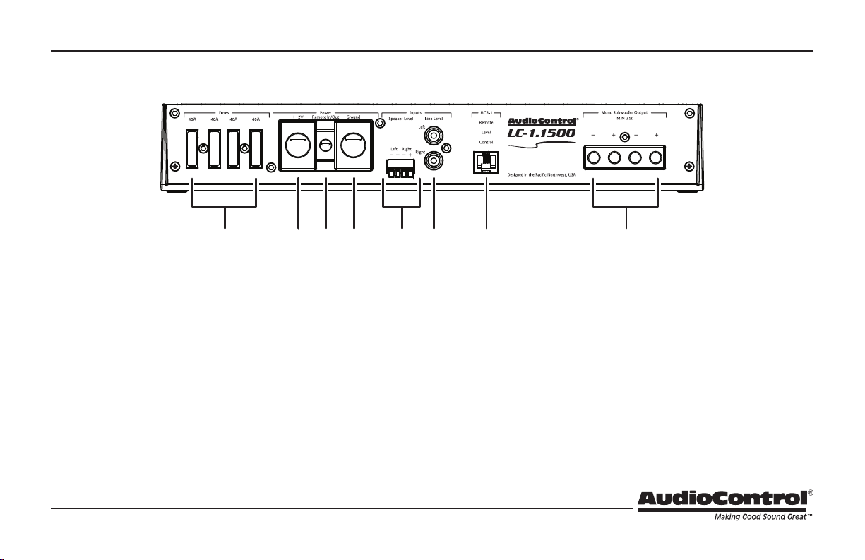
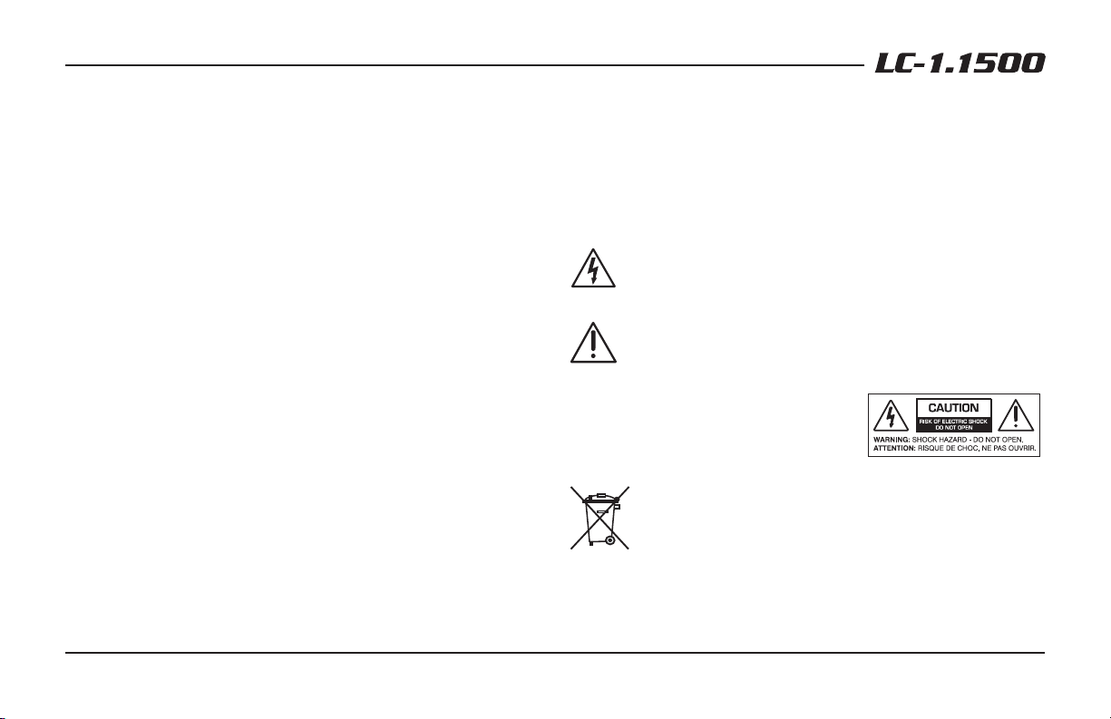
Connection Panel Features
1 2 3 4 5 6 7
1. Fuses 40A – Replace the fuses only with the exact same style
and Ampere rating. Disconnect 12V power before changing or
inspecting the fuses.
2. Power Input Terminal +12V – This screw terminal connects to
the +12V battery binding post of the vehicle. Use quality insulated
wiring of the recommended wire gauge, such as wire gauge 2 or
thicker. Thinner wire may cause an overheating hazard due to the
large currents involved.
3. Remote Power Input Terminal – This screw terminal connects
to the 12V remote trigger output of some head units. When the
head unit is turned on, then the LC-1.1500 amplier will turn on.
Alternatively, you can use the GTO feature of the amplier so it
will turn on when an audio signal is detected at the speaker-level
or line-level inputs.
8
4. Power Input Terminal Ground – This screw terminal connects to
a good ground connection on the vehicle.
5. Speaker-Level Inputs – The LC-1.1500 amplier is supplied with
a standard 4-conductor plug that allows for easy installation and
removal. The speaker-level output from ampliers and factory
installed radios can connect here, so the LC-1.1500 will receive
the audio signals and do its subwoofer thing. The left and right
audio signals are summed internally to produce a mono subwoofer signal. Make sure that you follow the plus and minus polarity
markings on the LC-1.1500 and match it to the polarity of the
speaker wiring. Do not use the RCA Line-level inputs if you are
using the speaker-level inputs.
3
Page 4

6. RCA Analog Line-Level Inputs – The line-level output from the
head unit or factory installed radios can connect here, so the
LC-1.1500 will receive the line-level audio signals. The left and
right signals are summed internally to produce a mono subwoofer
signal. Do not use the speaker-level inputs if you are using the
RCA line-level inputs.
7. Remote Control Connector – This connects to the optional ACR-1
remote control and allows you to remotely control the output
level.
8. Speaker-Level Output Terminals – These screw terminals connect with speaker wire to the subwoofer, or multiple subwoofers.
Make sure that the average combined speaker impedance does
not dip below 2 Ohm. The LC-1.1500 has four connections (2 plus
and 2 minus).
4
Quick Start Guide
Page 5

Control Panel Features
9 10 11 12 13
9. Power LED – If you have connected your battery power, vehicle
ground, and turn-on lead (or GTO signal sensing) correctly, then
this light should be green to indicate the power is ON. An internal
blue glow will also emanate from the heatsink area to indicate
that the power is ON. There are times when this blue glow will
ash, such as during power-up, and when the protection circuits
have detected a problem.
10. Protection LED – The LC-1.1500 amplier has built in diagnostic
codes to tell you exactly what is going wrong should the amplier
detect a problem. (See specs page for a list of diagnostic codes.)
If the protection LED should come on, read the red codes quickly
before turning o the system and investigating. Shorts, like
crushed-velvet hot pants, are not a good thing. Note that the blue
power codes mentioned in the table are for the internal blue glow
from behind the heatsink area, and not the power LED which is
green. You might not notice the subtle blue glow at rst, unless
you are in the dark or the shade.
14
11. GTO Signal Sense – In the ON position, the LC-1.1500 amplier
will turn on gracefully when it detects an incoming audio signal,
and it will turn o after a period of time when the audio signal
fades away to silence. In some situations, factory installed audio
systems may turn on or “wake up” due to convenience features
like door chimes, alarms, and cell phone signals that trigger the
source unit in the vehicle to come on. To prevent these from
turning your audio system on unexpectedly, you can bypass the
GTO circuit by moving the GTO switch to the OFF position and use
a switched 12-volt signal connected to the Remote In terminal
instead.
16 1715
5
Page 6

6
12. AccuBASS®
Enables/Disable – Turns the AccuBASS® circuit on or o . The
renowned AccuBASS® will work wonders on the lower bass of the
speaker outputs.
AccuBASS® Threshold – Selects the level at which the AccuBASS®
will begin to work.
AccuBASS® Level – Adjusts the level of the AccuBASS®.
13. Crossover Frequency – Since component speakers (like woofers)
are designed to reproduce certain frequency ranges, a crossover
allows you to match the speaker to the appropriate frequency
range. Most manufactures list a recommended crossover frequency as part of the speaker specications. Choosing the correct
crossover point will provide increased speaker reliability and
optimum sound quality. The LC-1.1500 amplier comes with an
adjustable-frequency 24/dB Octave Linkwitz-Riley crossover. Adjust the crossover frequency on the LC-1.1500 amplier to match
the value specied by your subwoofer’s manufacturer. If you do
not know this value, start out with the crossover selector turned
all the way to the left (counter clockwise) and adjust it until you
nd a position that suits your subwoofer system best.
14. Gain Control – This control allows you to adjust the overall
volume output level in the normal way, with counterclockwise
decreasing the volume, and clockwise increasing. Note that if
you have tted the optional ACR-1 gain control, it should rst
be set to maximum, before setting this gain control. The setting
procedure is given on the next page, and involves nerves of steel,
a steady hand, grit, determination, and the thought that you are
making the world a better place for deep bass.
15. Polarity – This switch allows you to select the polarity of the subwoofer, either 0 degrees (in-phase) or 180 degrees (out of phase).
16. Source Clip LED – The LC-1.1500 amplier features our MILC™
(Maximum Input Level Control) patent-pending level-setting circuit that prevents clipping and damaging distortion. It calculates
when the waveform of an incoming audio signal is clipping, and if
it is, this LED will fulll its prime objective and shine forth.
With this advanced feature, you are able to optimize the level of
the incoming audio signal until the Source Clip LED is just-prior
to lighting. If the LED comes on during normal operation, you
should adjust the level of the audio signals before they reach the
LC-1.1500.
17. Gain Maximized LED – This LED indicates when the LC-1.1500
amplier gain has been maximized for optimum performance.
Quick Start Guide
Page 7

Quick Start
1. It only takes a few steps to get your LC-1.1500 amplier up and
running!
2. Undo the +12V and Ground connections to the car battery
before making any connections to the amplier.
3. When making connections, designate red RCA plugs as right,
and designate white, black, or grey plugs as left. This is a good
idea for all signal connections made in your audio system. The
key is consistency. Stick with the same color coding and you’ll
reduce possible problems.
4. Use quality interconnect cables. We know from experience that
really cheap cables can cause a multitude of problems. They
tend to break inside or corrode, causing a loss of signal or hum.
They also have poor shielding.
5. Connect the +12V input terminal of the unit to the +12V terminal of the vehicle battery. Use 2 gauge insulated wire or thicker.
6. Connect the Ground terminal of the unit to the chassis of the
vehicle. Use 2 gauge insulated wire or thicker.
7. Connect the remote power terminal of the unit to the remote
turn-on switch of your source unit. Alternatively, you can skip
this connection and use the GTO Signal sensing which is explained later in this manual.
8. Connect your audio inputs to the unit – either speaker-level or
line-level RCA… not both.
9. Run the optional ACR-1 remote to the front of the vehicle to
adjust the bass level on the y.
10. Connect your subwoofer (2 Ohms minimum load).
11. When all connections are made, reconnect the vehicle battery.
12. Adjust your input source gain using the Patent Pending MILC.
This will indicate if the incoming audio signals are clipping.
13. Set the LC-1.1500 crossover to the frequency recommended by
the subwoofer manufacturer.
14. The optional ACR-1 adjusts the overall output level.
15. Enjoy the drive!
7
Page 8

Power Connections
Head Unit
Remote Amplifier
+12V Trigger
+12V
Ground
8
In this example, the head unit has a +12V trigger
output that is connected to the LC-1.1500 remote
input terminal. When the head unit is turned on, it
will turn on the LC-1.1500 amplier.
Alternatively, the GTO signal sense feature can
be used to gently turn on the LC-1.1500 amplier
when an audio input signal is detected. (The connection to the LC-1.1500 remote input terminal is
not required when using the GTO signal sense.)
Quick Start Guide
Page 9

System #1: Adding a Subwoofer to a Factory Radio using Speaker-Level Inputs
Factory
Radio
ACR-1
(optional)
Speaker-level
output
+
+
Subwoofer
9
Page 10

System #2: Adding a Subwoofer to an Aftermarket Head Unit
using Line-Level Inputs
Aftermarket
Head Unit
10
ACR-1
(optional)
Line-level
outputs
L/R
L/R
+
+
Subwoofer
Quick Start Guide
Page 11

ACR-1 Dash Control Installation
The optional AudioControl ACR-1 dash control is a remote level control for your LC-1.1500 amplier. It may be mounted under the dash
using its own enclosure, or through a custom hole in the dash. The
level control knob should be within reach of the driver, and in a spot
where the LED is plainly visible. Disconnect the vehicle battery +12V
and Ground connections before installation.
Dash Bracket Installation: The dash control mounts with two
screws, which attach to the underside of the dashboard. Slide
under the dash and place the dash control in its mounting
position, mark the two best mounting holes, drill pilot holes, and
secure with two screws.
Custom Installation: For that custom, nished look, the dash control
can be ush-mounted directly on the dashboard (or anywhere
else). Disassemble the ACR-1 from its enclosure.
Top Lid Removal
The top lid must be removed to gain access to the controls, and then
put back on again to protect the controls from dust bunnies.
Removal Procedure
1. Locate the two screws that hold the straight edge of the lid onto
the connector side of the amplier.
2. Use the supplied hex key to loosen both screws just enough
until this edge of the lid can lift freely up just a little. (There is no
need to remove the screws all the way, in case you lose them.)
3. Slide the lid toward the heatsink ns just a tad, before further
lifting the straight edge of the lid about 2”, then disengage the
remaining two points of contact (under the wavy edge).
4. Place the lid in a safe and handy place, ready for the time when
you have nished adjusting the controls to your immense satisfaction.
11
Page 12

Specications
All specications are measured at 14.4 VDC (standard automotive voltage). As technology advances, AudioControl reserves the right to continuously
change our specications, like our Pacic Northwest weather, although we are working on changing that as well.
The LC-1.1500 Amplier
Power Output (RMS) ............................850 Watts @ 4 Ohms
. . . . . . . . . . . . . . . . . . . . . . . . . . . . . . . . . . . . . . . . . . . . . . . .1500 Watts @ 2 Ohms
Input Voltage (RCA) Range ........................ 500mV to 6V RMS
Speaker-Level Input Voltage Range . . . . . . . . . . . . . . . . . . . .3V to 40V RMS
Total Harmonic Distortion . . . . . . . . . . . . . . . . . . . . . . . . . . . . . . . . . . . < 0.01%
S/N Ratio ..........................102 dBa, Ref 750 Watts @ 4 Ohms
Damping Factor ...............670 @ 10 Volts, 4 Ohms Output, 100 Hz
Bass Processing ..........................................AccuBASS®
Recommended Power / Ground Wire Gauge ............ 0 to 2 Gauge
Fuse Rating .............................................4 X 40 Amps
Crossover. . .24 dB/Octave Linkwitz-Riley, Adjustable From 30 - 250 Hz
PFM Subsonic Filter ........................................... 24 Hz
Weight .......................................................7.2 lbs
Dimensions ................................... 12" W X 8.0" D X 2.1" H
©2018 AudioControl. All rights reserved.
Warranty
For details of the limited warranty for your LC-1.1500, please visit the following
page on our website: http://www.audiocontrol.com/warranty
Please keep your receipt in a safe place.
Power (Blue) Codes
Power Up
Reset Boot
Protection Activated
Protection (Red) Codes
1
Short
2
Repeated Short
3
Under Voltage
4
Over Voltage
5
DC Oset
6
Thermal Heatsink
7
Thermal Transformer
(These are the blue LEDs inside the unit)
(This is the red Protection LED on the unit)
AudioControl
22410 70th Avenue West, Mountlake Terrace, WA 98043 USA,
Phone 425-775-8461, FAX 425-778-3166
e-mail: sound.great@audiocontrol.com
Quick Start Guide PN 914-020-0 Rev A
 Loading...