

Page 1
HIGH-POWER SUBWOOFER AMPLIFIERS
Installation Manual
AND
Page 2
2
Installation Manual
Important Safety Instructions
1. Read these instructions.
2. Keep these instructions.
3. Heed all warnings.
4. Follow all instructions.
5. Do not use this apparatus near water.
6. Clean only with a dry cloth.
7. Do not block any ventilation openings. Install in accordance with the
manufacturer’s instructions.
8. Do not install near any heat sources such as muers, silencers, exhaust
pipes, or other apparatus (including ampliers) that produce heat.
9. WARNING: Improper installation may lead to permanent injury or death.
Installation of the apparatus must be done with great care by qualied
personnel, to prevent damage to fuel lines, power and other electrical
wiring, hydraulic brake lines, and other systems, that might compromise
vehicle safety.
10. Provide +12V and Ground wiring of sucient size to ensure adequate
current to the amplier. For the Epicenter 600 / 1200 this means 4 gauge
wire or lower.
11. Use rubber grommets to protect wiring whenever passing wires through
metal openings or bulkheads.
12. Only use attachments/accessories specied by the manufacturer.
13. Refer all servicing to qualied service personnel. Servicing is required
when the apparatus has been damaged in any way, such as the power input terminals are damaged, liquid has been spilled or objects have fallen
into the apparatus, the apparatus has been exposed to rain or moisture,
does not operate normally, or has been dropped.
14. This apparatus shall not be exposed to dripping or splashing, and no
object lled with liquids, shall be placed on the apparatus.
15. Fuses shall be replaced only with the correct type and fuse value, and
only when the apparatus is powered o.
16. Exposure to high sound pressure levels may lead to permanent hearing
loss. Take every precaution to protect your hearing.
The lightning ash with arrowhead symbol within an equilateral
triangle is intended to alert the user to the presence of uninsulated
“dangerous voltage” within the product’s enclosure, that may be of
sucient magnitude to constitute a risk of electric shock to persons.
The exclamation point within an equilateral triangle is intended to
alert the user of the presence of important operating and maintenance (servicing) instructions in the literature accompanying the
appliance.
Caution: to reduce the risk of electric shock, do
not disassemble the apparatus, other than to
remove the top panel to access the controls.
There are no user-serviceable parts inside. Refer
servicing to qualied personnel.
Recycling notice: If the time comes and this apparatus has fullled
its destiny, do not throw it out into the trash. It has to be carefully
recycled for the good of mankind, by a facility specially equipped
for the safe recycling of electronic apparatii. Please contact your
local or state recycling leaders for assistance in locating a suitable
nearby recycling facility. Or, contact us and we might be able to
repair it for you.
Page 3

3
Table of Contents
©2015 AudioControl Inc All rights reserved.
Important Safety Instructions ....................................2
Chapter 1: Introduction ...........................................4
Introduction ...................................................4
Congratulations! ...............................................4
Features. . . . . . . . . . . . . . . . . . . . . . . . . . . . . . . . . . . . . . . . . . . . . . . . . . . . . . . .5
Complimentary bullet points ...................................6
Chapter 2: Quick Start Guide .....................................7
Quick View .....................................................7
Quick Start .....................................................8
Chapter 3: Hookup Diagrams .....................................9
Power Connections .............................................9
System #1 .....................................................10
System #2: ....................................................11
System #3: ....................................................12
Chapter 4: Installation ...........................................13
Installation ....................................................13
ACR-3 Dash Control Installation ................................15
Top Lid Removal and Installation ...............................16
Speaker Connections ..........................................17
Speaker and Wiring Impedance ................................17
Chapter 5: Features ..............................................18
Connection Panel Features ....................................18
Control Panel Features .........................................20
Chapter 6: Adjusting The System ................................24
Adjusting the System ..........................................24
Chapter 7: Troubleshooting .....................................25
Troubleshooting ..............................................25
Chapter 8: Specications ........................................27
Specications .................................................27
Block Diagram .................................................28
Dimensions ...................................................29
Chapter 9: Service ...............................................31
Service ........................................................31
Chapter 10: Please Remain Calm .................................32
The Warranty ..................................................32
Legalese Section ..............................................33
Chapter 11: Complementary Doodle Pages ......................34
Favorite Settings ..............................................34
Page 4

4
Installation Manual
Simply the most advanced subwoofer ampliers in car audio today!
The Epicenter® 600 and 1200 ampliers incorporate our patented
bass restoration processor to deliver earth-shaking power to your
subwoofer system. Carefully applied signal processing at just the right
spot, enhances the listening experience and maximizes your bass
quality. In a real-world listening environment, we invite you to compare this amplier to any other amplier in the same power category,
at any price, and you will quickly learn that the Epicenter ampliers
will always have more bass! It’s time to hear what you have been
missing.
More than that
The Epicenter amplier is not a cold heartless box for increasing
the loudness of bass frequencies in your system. It restores the bass
frequencies to how they were meant to be. It is a bass-frequency
re-enactor. Your favorite music will come alive and breath, and live
again, and you will hear its presence like you haven’t heard it before.
That’s how good it is.
AudioControl’s engineering department designed these ampliers
from the ground up. They feature a black brushed aluminum nish,
with black powder-coated cast alloy heat sinks and bottom panel in
one single piece. A black-brushed aluminum cover is also provided to
protect the controls from the prying hands of carnival clown folk who
have wronged you.
Congratulations!
You are now installing a component which will dramatically improve
the performance of any low-frequency car audio system, especially
those requiring lots and lots of low-frequency earth-shattering, teacup rattling, denture crumbling performance, in a car.
The Epicenter ampliers provide high levels of power, pristine sound
quality, exible inputs, plus a number of installation-friendly features
that makes them the perfect product for performance oriented audio systems. The ampliers are American-designed “set and forget”
components which will provide a lifetime of trouble-free service for
your Earth-surface roving vehicle, and orbital, interplanetary, and
interstellar transportation systems.
The Epicenter ampliers are designed by AudioControl, the only electronics company in the world that specializes in ampliers, equalizers,
signal processors and audio analyzers. Our passion for high quality,
meticulous attention to detail, and pro sound heritage shows itself
in the dozens of awards we have won for our designs, products, and
service.
Now, as when we began, our greatest satisfaction is our reputation for
sonic excellence and reliability among people just like you throughout the world.
This manual is designed to help you get the best out of this amplier.
So, even though you’re dying to see it in action, please take a few
minutes to slog through our not-so-weighty prose and learn how to
get the most from your Epicenter amplier.
Introduction
Chapter 1: Introduction
Page 5

5
Features
Here are some of the features that make the Epicenter 600 and 1200
ampliers very unique and unlike any other ampliers:
• Superior Sound Quality
Pristine sonics happens rst in all AudioControl designs and
is not compromised by any other feature. (You often get the
feeling that sound quality is an afterthought with products from
other companies.)
• High Power Levels
The high-eciency Class D monoblock subwoofer amplier is a
high-current design, capable of driving subwoofer loads down to
1 Ohm impedance.
The output power of the Epicenter 600 is 600 Watts into 1 Ohm,
and the Epicenter 1200 is 1200 Watts into 1 Ohm.
• Unparalleled Energy Eciency
Whether from the point of view of reducing current draw, or
from the viewpoint of less heat in the trunk, the Epicenter 600
and 1200 subwoofer ampliers have no equal. They are VERY
energy ecient during operation.
• The Epicenter Bass Restoration
The Epicenter Sweep and Epicenter Width controls allow you to
restore any low frequencies that may be aected by the vehicle
acoustics, speaker and enclosure design and location, and the
performance recording process.
• MILC™ Maximum Input Level Control
The Epicenter amplier analyses the incoming audio signals and
detects any signal clipping. This gives you the chance to optimize
the audio signal levels going in to the Epicenter amplier.
• ACR-3 Wired Remote
This dash-mounted remote allows easy adjustment of the output
level, and the level of the Epicenter bass restoration.
• Self Resetting Protection Features
Protection features are extensive and include thermal, short circuit, clipping, under voltage, over voltage, and DC oset among
others. If the fault is removed, the unit may reset. The protection
LED ashes with various codes that indicate the fault detected.
• Pacic Northwest Heritage
The engineers who designed this amplier are native
Northwesterners, steeped and learned in the long and impressive audio engineering history of Washington State, and all able
to reach their catch limit during razor-clam digging season. We
are very proud of that fact. What is more important is the care we
craft in at every step, and the extensive knowledge we have in all
aspects of the product. Plus, we back this up with a conditional
ve year warranty.
Chapter 1: Introduction
Page 6

6
Installation Manual
• Class D Monoblock Subwoofer Amplier
• High Current Design - 1 Ohm Stable
• 600 Watts @ 1 Ohm (The Epicenter 600 Amplier)
• 1200 Watts @ 1 Ohm (The Epicenter 1200 Amplier)
• The Epicenter Digital Bass Restoration
• MILC™ Maximum Input Level Control (Patent Pending)
• 24 dB/Octave Linkwitz-Riley Alignment Crossover
• GTO Signal Sense
• PFM Subsonic Filter
• Line-Level RCA Inputs and Active Speaker-Level Inputs
• Solid One-Piece Aluminum Chassis
• Wired ACR-3 Remote Control for Subwoofer Level and the Epicenter Processor
• Expansion Bus
• Adds a weird blue glow of mystery to your trunk/boot installation
• Kind to Kittens™
• Calculus-enriched
Complimentary bullet points
Chapter 1: Introduction
Page 7
7
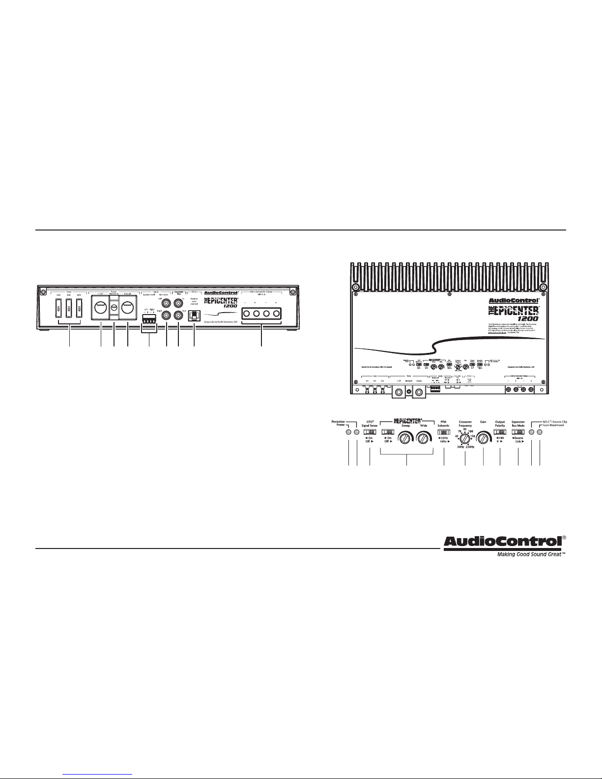
10. Power LED
11. Protection LED
12. GTO Signal Sense
13. Epicenter Controls:
On/O, Sweep, Wide
14. PFM Subsonic 16Hz/32Hz
15. Crossover Frequency
16. Gain Control
17. Polarity
18. Expansion Bus Mode
19. MILC™ Source Clip LED
20. Gain Maximized LED
1. Fuses 40A
2. Power Input Terminal +12V
3. Remote Power Input Terminal
4. Power Input Terminal Ground
5. Speaker-Level Inputs
6. RCA Analog Line-Level Inputs
7. Expansion Bus In and Out
8. Remote Control Connector
9. Speaker-Level Outputs
1 2 3 4 5 6 7
8
9
10 11 12 13 14 15
16
19 2017 18
Controls (top panel removed)
Quick View
Front Panel
Chapter 2: Quick Start Guide
Note: The Epicenter 1200 is shown. The Epicenter 600 has the same
controls and features, except for two fuses, and dierent power terminals and speaker-level output terminals.
Page 8

8
Installation Manual
Quick Start
1. It only takes a few steps to get your Epicenter amplier up and
running in a ash! The steps below are explained in more detail
throughout this manual.
2. Undo the +12V and Ground connections to the car battery
before making any connections to the amplier.
3. When making connections, designate red RCA plugs as right,
and designate white, black, or grey plugs as left. This is a good
idea for all signal connections made in your audio system. The
key is consistency. Stick with the same color coding and you’ll
reduce possible problems.
4. Use quality interconnect cables. We know from experience that
really cheap cables can cause a multitude of problems. They
tend to break inside or corrode, causing a loss of signal or hum.
They also have poor shielding.
5. Connect the +12V input terminal of the unit to the +12V terminal of the vehicle battery.
6. Connect the Ground terminal of the unit to the chassis of the
vehicle.
7. Connect the remote power terminal of the unit to the remote
turn-on switch of your source unit. Alternatively, you can skip
this connection and use the GTO Signal sensing which is explained later in this manual.
8. Connect your audio inputs to the unit – either speaker-level or
line-level RCA… not both.
9. Run the ACR-3 remote to the front of the vehicle to adjust the
bass level and the Epicenter eect on the y.
10. Connect your subwoofer (1 Ohm minimum load).
11. When all connections are made, reconnect the vehicle battery.
12. Adjust your input source gain using the Patent Pending MILC.
This will indicate if the incoming audio signals are clipping.
13. Set the Epicenter’s crossover to the frequency recommended by
the subwoofer manufacturer.
14. Adjust the Epicenter sweep and wide controls for maximum bass
restoration. The ACR-3 adjusts the level of this eect, and the
overall output level.
15. Enjoy the drive!
Chapter 2: Quick Start Guide
Page 9
9
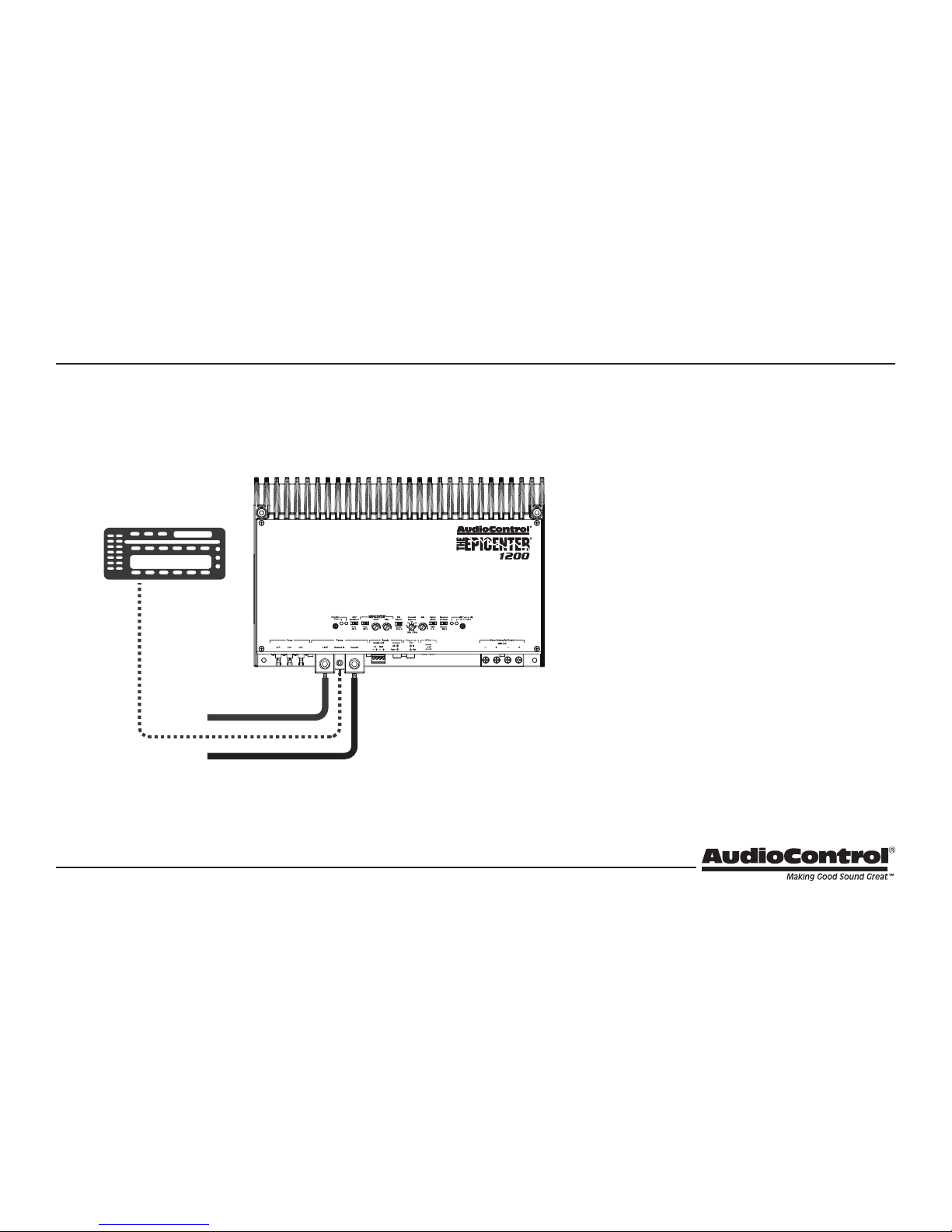
Power Connections
Ground
Head Unit
Remote Amplifier
+12V Trigger
+12V
In this example, the head unit has a +12V trigger
output that is connected to the Epicenter’s remote
input terminal. When the head unit is turned on, it
will turn on the Epicenter amplier.
Alternatively, the GTO signal sense feature can be
used to gently turn on the Epicenter amplier when
an audio input signal is detected. (And the connection to the Epicenter’s remote input terminal is not
required.)
Chapter 3: Hookup Diagrams
Page 10
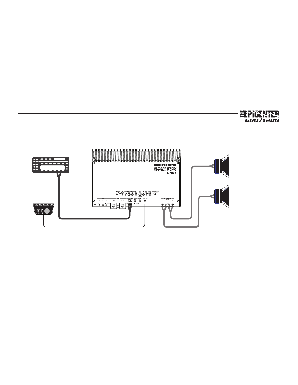
10
Installation Manual
Factory
Radio
Speaker-level
output
+
+
ACR-3
Subwoofers
System #1: Adding Subwoofers to a Factory Radio
Chapter 3: Hookup Diagrams
Page 11
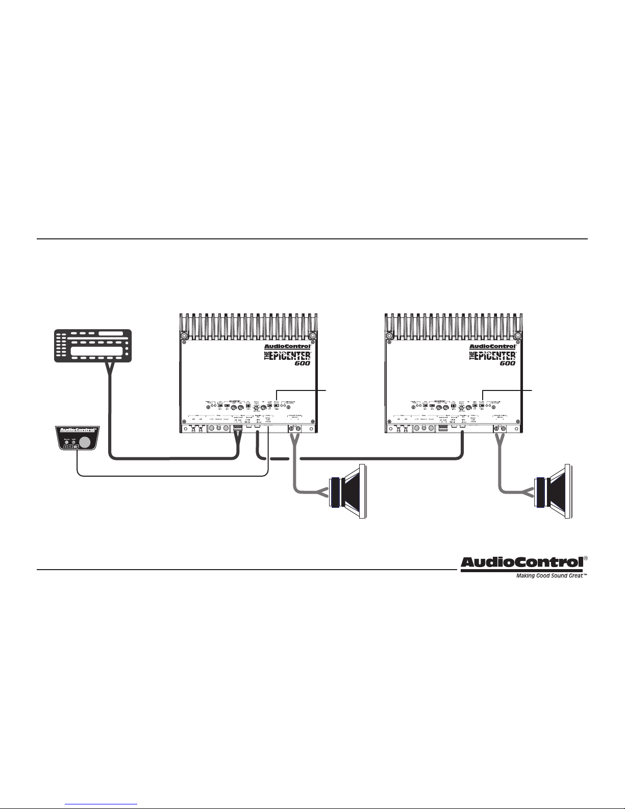
11
Left
Subwoofer
Right
Subwoofer
Factory
Radio
ACR-3
Master
Expansion Bus
Mode: Source
Expansion Bus
Mode: Link
+ +
Speaker-level
output
InOut
System #2: Using the Expansion Bus to run multiple Ampliers, linked to one
Master set of Controls
Chapter 3: Hookup Diagrams
Page 12

12
Installation Manual
Factory
Radio
Subwoofer
+
+
+
ACR-3
Master
Link
180˚
Source
0˚
Speaker
level
output
System #3: Using the Expansion Bus to run two Ampliers to double
the power into one Subwoofer
Note: In this example, the subwoofer impedance
should not be less than 2 Ohms
Chapter 3: Hookup Diagrams
Page 13

13
Installation
We recommend mounting the Epicenter amplier in the trunk/boot
or cargo area of the vehicle. An alternative location would be under
the front seat of your vehicle if there is enough room to install and
also to reach the controls. When choosing a location, please keep
these things in mind:
1. Before you start, disconnect the +12V positive and negative
cables from the battery in the vehicle to prevent any damage to
the vehicle or the amplier during the installation process.
2. Pick a mounting location that will provide access to the controls
and connections, provide adequate ventilation, and also protect
the amplier from heat, moisture, and dirt. Make sure the ventilation slots on the sides are not blocked, and that the heatsink
ns are not covered.
3. The Epicenter amplier needs to be securely mounted using the
four mounting holes located in each corner of the Epicenter amplier. See page 29 and 30 for dimensioned drawings that show
the mounting hole locations.
4. Before drilling any holes, take every precaution to prevent damage to fuel lines, power and other electrical wiring, hydraulic
brake lines, and other systems, that might compromise vehicle
safety.
5. Always mount the amplier as far from the antenna in the vehicle as possible. At the same time you will want to install your
amplier away from the radio or any other RF sensitive electronics in the vehicle.
6. Use a sucient gauge power cable that is connected to and
fused properly at the positive terminal of the battery. Use this
table to determine the correct wire gauge for your particular
installation.
7. The amplier should be grounded with a short, heavy gauge
wire connected directly to the car chassis at a bare metal surface clear of any paint, undercoating, etc. Do not use factory
ground locations, seat bolts, or brackets that have spot welds.
Many newer vehicles incorporate crumple zones, and what may
appear to be a good ground may not be. Always verify using an
Ohm meter.
System
Amperage
7-10
Feet
10-13
Feet
13-16
Feet
16-19
Feet
19-22
Feet
22-28
Feet
35 – 50 8 6 4 4 4 4
50 – 65 6 4 4 4 4 2
68 – 85 4 4 2 2 2 0
85 – 105 4 2 2 2 2 0
105 – 125 4 2 0 0 0 0
125 – 150 2 0 0 0 0 0
Chapter 4: Installation
Page 14

14
Installation Manual
8. The Epicenter amplier has speaker-level inputs that are designed to accept an amplied, speaker-level signal from a factory source unit or amplier. You may need to refer to a factory
service manual or wiring-harness schematic to determine which
wires are the speaker wires for your system. If you are unsure
which are the speaker wires, we recommend you look at the
color of the speaker wires connected to the speakers and follow them back to the source. Connect the speaker wires to the
Epicenter amplier’s green speaker-level input plug using the
correct polarity. It is critical that the audio output you use is full
frequency range, so the factory rear speaker wires would generally be the optimum choice. Connecting to the factory subwoofer wire is not recommended.
9. Line-level audio signals will generally come from your aftermarket radio, or if you are really getting the most out of your car
audio system they may be coming from a really awesome product like the AudioControl DQDX!! (Shameless plug). There are
generally only two things to consider when using the line-level
RCA inputs: 1. Use good shielded or twisted pair RCA cables and
2. Run your RCA cables at least 18” away from power and speaker
cables to avoid picking up radiated noise in your system.
Chapter 4: Installation
Page 15

15
ACR-3 Dash Control Installation
The AudioControl ACR-3 dash control is a dual-function remote for
your Epicenter amplier. It may be mounted under the dash using its
own bracket, or through a custom hole in the dash. The endless knob
should be within reach of the driver, and in a spot where the two LEDs
are plainly visible. Disconnect the vehicle battery +12V and Ground
connections before installation.
Dash Bracket Installation: The dash control mounts with two
screws, which attach to the underside of the dashboard. Slide
under the dash and place the dash control in its mounting
position, mark the two best mounting holes, drill pilot holes, and
secure with two screws.
Custom Installation: For that custom, nished look, the dash control
can be ush-mounted directly on the dashboard (or anywhere
else). Disassemble the ACR-3 from its mounting bracket. Start by
pushing the LEDs from their holders, followed by removing the
circuit board and rotary control knob from the bracket. Carefully
drill a 9/32” hole in the dashboard for the control, a 1/8” hole for
the lock tab and two 13/64” holes for the LED holders. Reassemble the dash control components securely onto the dash.
1. When the red LED is on, turn the remote knob clockwise to turn
the subwoofer level up, and counterclockwise to turn it down.
As it is an endless knob, turning it more than one turn clockwise
would be maximum, and more than one turn counterclockwise
is minimum. During the ‘set-up’ part of your installation, make
sure that the remote knob is turned all the way up in subwoofer
mode (red LED on) before you make any adjustments to the
amplier. In this way you will not overdrive anything if the knob
was set at a lower level.
2. Press the remote knob, and the blue LED turns on and red turns
o. The knob can now adjust the overall level of the Epicenter
bass restoration eect. (The sweep and width are set by the controls on the main unit, the remote knob sets its wet/dry level.)
Chapter 4: Installation
Page 16

16
Installation Manual
Top Lid Removal and Installation
Re-installation Procedure
1. Ensure that the two M3 x 10 mm screws on the straight edge of
the lid are present and backed out a tad until the front edge of
the screws are ush with the threads in the lid. If you have lost
them (tut-tut), then use only M3 x 10 mm screws and no longer
than that.
2. Align the wavy edge of the lid along the heatsink ns, and lower
the straight edge of the lid to 2” above the surface of the amplier.
3. Slide the lid towards the connectors, engaging the top two
points of contact under the wavy edge of the lid.
4. Lower the lid at onto the surface of the amplier.
5. Secure the two M3 x 10 mm screws near the connectors using
the 2.5 mm hex key*
* If your school metalwork teacher was a 6’5” rugged giant of a man, an ex-Royal Marine Commando called Tiny, and he insisted that these be called hexagonal wrenches and not hex keys or
Allen Keys, then so be it.
The top lid must be removed to gain access to the controls, and then
put back on again to protect the controls from dust bunnies, food
crumbs, and other dirt and grime.
Removal Procedure
1. Locate the two M3 x 10 mm screws that hold the straight edge
of the lid onto the connector side of the amplier.
2. Use the supplied 2.5 mm hex key to loosen both screws just
enough until this edge of the lid can lift freely up just a little.
(There is no need to remove the screws all the way, in case you
lose them.)
3. Slide the lid toward the heatsink ns just a tad, before further
lifting the straight edge of the lid about 2”, then disengage the
remaining two points of contact (under the wavy edge).
4. Place the lid in a safe and handy place, ready for the time when
you have nished adjusting the controls to your immense satisfaction.
Chapter 4: Installation
Page 17

17
Speaker Connections
Establish a standard connection color code and stick with it. One
conductor of the speaker wire is normally marked by a dierent color
(silver versus copper) or there is a ribbing on one side. Typically this
marked conductor is used for the positive (+) speaker leads. Really
good wire has Positive and Negative printed right onto the wire
jacket.
Match the polarity markings on the unit with the polarity markings
on your speakers.
Speaker and Wiring Impedance
Speaker impedance often is and should be straight forward. Speakers,
like other resistors, if wired in parallel “show” lower values than the
individual components. Here are two examples for calculating speakers wired in parallel:
Calculating Impedance
For three 8 Ohm speakers wired in parallel (pluses connected to
pluses) the impedance is 1/8 + 1/8 + 1/8 = 3/8
Then take the inverse or 8/3 = 2.66 Ω
For two 8 Ohm speakers wired in parallel (pluses connected to
pluses) the impedance is 1/8 + 1/8 = 2/8
Then take the inverse or 8/2 = 4 Ω
Often the real world is more complicated than theory, and for speakers this is the case. An eight Ohm speaker is not eight Ohms at all
frequencies. Plus passive crossover networks add their own changing
conditions. Be aware of speakers that have signicant dips from “nominal” values in portions of their frequency range, and speakers that are
rated at unusual impedances, for example 3.5 Ohms. The Epicenter is
tolerant of lower impedance loads down to 1 Ohm, however, all good
designs use some margin of error.
Your choice of speaker wire gauge and the length of the runs, also
aects the speaker impedance load presented to the ampliers. Even
fairly short speaker runs can have signicant resistance if you use a
smaller wire gauge. This can be a benet if you are paralleling lots of
speakers. The wire itself acts as an impedance limiter, since the amplier cannot see a speaker load lower than the resistance of the wire.
The downside of this wire resistance is that you waste some part of
the total power available to the speakers.
Chapter 4: Installation
Page 18

18
Installation Manual
1. Fuses 40A – There are two fuses on Epicenter 600, and three on
the Epicenter 1200 as shown. Replace the fuses only with the
exact same style and Ampere rating. Disconnect 12V power before changing or inspecting the fuses.
2. Power Input Terminal +12V – This screw terminal connects to
the +12V battery binding post of the vehicle. Use quality insulated
wiring of the recommended wire gauge, such as wire gauge 4 or
thicker. Thinner wire may cause an overheating hazard due to the
large currents involved.
3. Remote Power Input Terminal – This screw terminal connects
to the 12V remote trigger output of some head units. When the
head unit is turned on, then the Epicenter amplier will turn on.
Alternatively, you can use the GTO feature of the amplier so it
will turn on when an audio signal is detected at the speaker-level
or line-level inputs.
4. Power Input Terminal Ground – This screw terminal connects to
a good ground connection on the vehicle.
Connection Panel Features
1 2 3 4 5 6 7
8
9
Chapter 5: Features
Page 19

19
5. Speaker-Level Inputs – The Epicenter amplier is supplied with
a standard greenish plug that allows for easy installation and
removal. The speaker-level output from ampliers and factory
installed radios can connect here, so the Epicenter will receive the
audio signals and do its subwoofer thing. The left and right audio
signals are summed internally to produce a mono subwoofer signal. Always use the full frequency range outputs of the head unit
or radio, otherwise the Epicenter may be missing some important
bass information. Make sure that you follow the plus and minus
polarity markings on the Epicenter and match it to the polarity of
the speaker wiring. Do not use the RCA Line-level inputs if you are
using the speaker-level inputs
6. RCA Analog Line-Level Inputs – The line-level output from the
head unit or factory installed radios can connect here, so the Epicenter will receive the line-level audio signals. The left and right
signals are summed internally to produce a mono subwoofer signal. Always use the full frequency range outputs of the head unit
or radio, otherwise the Epicenter may be missing some important
bass information. Do not use the speaker-level inputs if you are
using the RCA line-level inputs.
7. Expansion Bus Input and Output – These two RCA connectors
allow multiple Epicenter ampliers to be used in a system, with
one as a Master source unit whose controls can aect all other
Epicenter ampliers in line. A switch in the control section under
the top lid, allows the Epicenter amplier to be set to Link or
Source. Pages 11 and 12 show some charming illustrations of two
Epicenter ampliers using the Expansion Bus.
If set to Source, the amplier gets its audio input signals either
from the speaker-level inputs or the line-level inputs, and all
its controls work normally. The Expansion Bus output sends a
line-level output (a preamp out) to the Expansion Bus input of the
next Epicenter amplier. This output signal is aected by all the
controls of the rst Epicenter amplier.
If set to Link, then the Epicenter amplier gets its audio input from
the RCA Expansion Bus output of the rst Epicenter amplier, and
this rst one can control all linked ampliers.
8. Remote Control Connector – This connects to the ACR-3 remote
control and allows you to remotely control the bass level and the
Epicenter eect level.
9. Speaker-Level Output Terminals – These screw terminals connect with speaker wire to the subwoofer, or multiple subwoofers.
Make sure that the average combined speaker impedance does
not dip below 1 Ohm. The Epicenter 600 has two connections
(plus and minus) and the Epicenter 1200 has two of each (two
plus, in parallel, two minus, in parallel).
Chapter 5: Features
Page 20

20
Installation Manual
Control Panel Features
10 11 12 13 14 15
16
19 2017 18
Chapter 5: Features
Page 21

21
10. Power LED – If you have connected your battery power, vehicle
ground, and turn-on lead (or GTO signal sensing) correctly, then
this light should be green to indicate the power is ON. An internal
blue glow will also emanate from the heatsink area to indicate
that the power is ON. There are times when this blue glow will
ash, such as during power-up, and when the protection circuits
have detected a problem. See the table below.
11. Protection LED – The Epicenter amplier has built in diagnostic
codes to tell you exactly what is going wrong should the amplier
detect a problem. Below is a list of diagnostic codes to help you
understand what is going on with your amplier:
If the protection LED should come on, read the red codes quickly
before turning o the system and investigating. Shorts, like
crushed-velvet hot pants, are not a good thing. Note that the blue
power codes mentioned in the table are for the internal blue glow
from behind the heatsink area, and not the power LED which is
green. You might not notice the subtle blue glow at rst, unless
you are in the dark or the shade.
12. GTO Signal Sense – In the ON position, the Epicenter amplier
will turn on gracefully when it detects an incoming audio signal,
and it will turn o after a period of time when the audio signal
fades away to silence. In some situations, factory installed audio
systems may turn on or “wake up” due to convenience features
like door chimes, alarms, and cell phone signals that trigger the
source unit in the vehicle to come on. To prevent these from
turning your audio system on unexpectedly, you can bypass the
GTO circuit by moving the GTO switch to the OFF position and use
a switched 12-volt signal connected to the Remote In terminal
instead.
6
7
3
1
2
4
5
Thermal Heatsink
Thermal Transformer
Under Voltage
Short
Power Up
Reset Boot
Protection Activated
Repeated Short
Over Voltage
DC Oset
Epicenter Amplier Codes:
Protection (Red) Codes
Power (Blue) Codes
Chapter 5: Features
Page 22

22
Installation Manual
13. EPICENTER Controls: On/O, Sweep, Wide – The bass response
in a system is aected by four factors;
The acoustics of the vehicle
The location of the speakers
The music: how it was recorded AND how it is being played back
Speakers and speaker enclosures
Because of the variations in the recording process, we developed
the Epicenter to help restore any low frequencies lost during the
recording process; however, the acoustics of various environments are dierent. With this in mind, our engineers developed
the unique Para BASS system for the Epicenter amplier.
The Sweep control allows you to select a center frequency (the
frequency most aected) between 27 and 63 Hz.
The Width control then allows you to control the shape of the
lter centered on the Sweep frequency.
The On/O switch allows you to turn this bass restoration system
on or o.
In operation, once the sweep and the width have been set, the
ACR-3 remote (in blue-LED mode) is used to adjust the level of the
bass restoration.
14. PFM Subsonic 16 Hz/32 Hz – Many car
audio systems truly push the limits of
their subwoofer without really knowing it. Tuned enclosures aect
the roll-o of many speakers, and yet lots of source material forces
the speakers to play lower than is good for them. The net result is
wasted amplier power and damaged speakers. The AudioControl
PFM lter is a programmable subsonic lter that allows the speaker to play only as low as it should be playing. Because every system is dierent, we allow you to select the PFM frequency (either
32 Hz or 16 Hz). Follow the recommendations of your subwoofer
manufacturer. If in doubt, try 32 Hz and see if that will work just as
well as 16 Hz.
15. Crossover Frequency – Since component speakers (like woofers)
are designed to reproduce certain frequency ranges, a crossover
allows you to match the speaker to the appropriate frequency
range. Most manufactures list a recommended crossover frequency as part of the speaker specications. (You did read their manual
didn’t you?) Choosing the correct crossover point will provide
increased speaker reliability and optimum sound quality. the
Epicenter ampliers come with an adjustable-frequency 24/dB
Octave Linkwitz-Riley crossover. Adjust the crossover frequency
on the Epicenter amplier to match the value specied by your
subwoofer’s manufacturer. If you do not know this value, start out
with the crossover selector turned all the way to the left (counter
clockwise) and adjust it until you nd a position that suits your
subwoofer system best.
Chapter 5: Features
Page 23

23
16. Gain Control – This control allows you to adjust the overall
volume output level in the normal way, with counterclockwise
decreasing the volume, and clockwise increasing. Note that the
ACR-3 gain control should rst be set to maximum, before setting
this gain control. The setting procedure is given on the next page,
and involves nerves of steel, a steady hand, grit, determination,
and the thought that you are making the world a better place for
deep bass.
17. Polarity – This switch allows you to select the polarity of the subwoofer, either 0 degrees (in-phase) or 180 degrees (out of phase).
This is useful if you are using two Epicenter ampliers to run a
single subwoofer. (See the hookup diagram on page 11.)
18. Expansion Bus Mode – There are two positions: Source and Link.
This super feature allows multiple Epicenter ampliers to be used
in a system, one as a master source and controller, and the others
as Links, getting their inputs from the master. (See pages 11 and
12 for examples.)
Source: the Epicenter amplier receives audio input signals either
from its speaker-level inputs or the line-level inputs. The expansion bus RCA output sends a line-level output (a preamp out) to
the expansion bus RCA input of the next Epicenter amplier (set
to Link). This line-level output signal is aected by all the controls
of the rst Epicenter amplier.
Link: the Epicenter amplier gets its audio input from the RCA
expansion bus output of the rst Epicenter amplier, and this rst
one can control all linked ampliers.
19. Source Clip LED – The Epicenter amplier features our MILC™
(Maximum Input Level Control) patent-pending level-setting circuit that prevents clipping and damaging distortion. It calculates
when the waveform of an incoming audio signal is clipping, and if
it is, this LED will fulll its prime objective and shine forth.
With this advanced feature, you are able to optimize the level of
the incoming audio signal until the Source Clip LED is just-prior to
lighting. If the LED comes on during normal operation, you should
adjust the level of the audio signals before they reach the Epicenter.
After an interview with the lead engineer included the words
“dierential calculus,” and some hieroglyphics on a chalk board,
the technical writer’s eyes glazed over and he had to be brought
round with a nice cup of tea and a donut or two with sprinkles.
20. Gain Maximized LED – This LED indicates when the Epicenter
amplier gain has been maximized for optimum performance.
Chapter 5: Features
Page 24

24
Installation Manual
If you have ever listened to a friend’s “Killer” car audio system and
were sad to hear lots of hiss, clicks, or pops, then you have experienced an improperly level-matched system. When a performance
autosound system is properly level-matched, you should get the maximum output from your source unit and your amplier without any
clipping. The following steps will help guide you through the process:
1. Before you begin, make sure that you are wearing good
quality hearing protection, as it is going to get very loud,
enough to damage your hearing. Bits of cotton wool in
the ears is not going to cut it. Do not attempt this on a
quiet Sunday morning in the church car park.
2. Turn down, or turn o the ampliers that power your main speak-
ers. This will help prevent damage to the other speakers in your
system.
3. Set the ACR-3 Remote (in red-LED mode) to maximum. (As it is an
endless control, then turning it more than one turn is considered
the maximum.)
4. Set the Epicenter amplier’s Gain control to minimum.
5. Set the source volume to minimum, and set the source bass and
treble controls as you expect them to be used during listening.
6. Start playing the signal material at the source device. The ideal
material would be an uncompressed, 100 Hz sinewave at -1 dBFS.
If you do not have such a test signal, choose uncompressed, full
Adjusting the System
volume music in the region of interest. This is a subwoofer amplier, so the region of interest is 20 Hz to 200 Hz. A good choice
would be “Shake Your Rump” from Paul’s Boutique (Capitol CDP 7
91743 2) where there is some prolonged passages of heavy bass.
A poor choice would be “Clair de Lune”, a lullaby, or a recording of
nger cymbals.
7. Increase the source volume just enough until the MILC Source Clip
LED begins to icker on the Epicenter amplier. This is an indication of low frequency clipping, and represents the very maximum
output of the source unit. (Behold the power of calculus at play
within the Epicenter amplier to detect clipping.) Note: If the head
unit has RCA line-level outputs, then there may not be enough
signal to reach clipping anyway. If you are using the speaker-level
outputs, then chances are that clipping is possible.
8. Now that the source is playing its loudest but not clipping, slowly
increase the Epicenter amplier’s Gain control until the “Gain Maximized” LED begins to icker, or if you hear the woofers begin to
bottom out, whichever comes rst. This represents the maximum
playback level for the system.
9. Your system gain has now been optimized.
10. Reset the source volume to minimum and the ACR-3 Remote (in
red-LED mode) to minimum, so there are no surprises when you
turn the system back on.
Chapter 6: Adjusting The System
Page 25

25
Troubleshooting
Many problems can be eliminated by re-checking the wiring and
settings of the unit. If a problem cannot be solved using the guide
below, please call the AudioControl team for further assistance, or
e-mail us at sound.great@audiocontrol.com
1. No Sound
a. Verify the Power LED is a splendid green.
b. Verify the Protection LED is O.
c. Verify the source unit is operating.
d. Check the speaker connections.
e. Check the power fuses on the Epicenter amplier.
f. Check the ACR-3 (in red-LED mode) is not at minimum.
2. Protection LED is ashing:
a. Check the red protection LED ashing sequence, and compare
the problem codes with this table. This will help you identify
the problem, like having your very own tiny blinking service
technician. (The blue mentioned in the table is the blue glow
from within, near the heatsink area, and not the Power LED.)
b. If the problem code indicates a short circuit, check the speaker
wiring, and check that the speakers are not shorted internally.
c. For under-voltage and over-voltage faults, check all the power
connections to the Epicenter, and check the vehicle power
generation system, loose fanbelt, du alternator, and so on.
6
7
3
1
2
4
5
Thermal Heatsink
Thermal Transformer
Under Voltage
Short
Power Up
Reset Boot
Protection Activated
Repeated Short
Over Voltage
DC Oset
Epicenter Amplier Codes:
Protection (Red) Codes
Power (Blue) Codes
d. For over-heating problems, make sure the Epicenter amplier
is receiving adequate ventilation.
e. Disconnect all speaker wires. If the protection LED is still ash-
ing, and the unit has cooled, something rather serious has
happened inside the unit. Call AudioControl’s lonely folks in
customer service.
Chapter 7: Troubleshooting
Page 26

26
Installation Manual
3. Source Clip LED is on:
a. Turn down the level of the audio signals entering the Epicen-
ter. The Epicenter analyses the incoming audio and detects if
the signal is clipping. Make sure the settings in other equipment in your system, such as EQ controls, are not over-done
and clipping the signals.
4. Speaker channels are cutting in and out:
a. Make sure the speaker impedance is not less than 1 Ohm.
b. There may be a short in the wires. Suspect a short if the prob-
lem happens only at the highest volumes.
c. Make sure the subwoofers are not being overdriven, beyond
their recommended level.
5. Speaker Buzzing or Crackling at high volume:
a. Reduce any preamplier/equalizer low-frequency boost.
b. Check the Epicenter’s Source Clip LED is not on.
c. Check the Epicenter’s Protection LED is not ashing a code
such as “under-voltage.”
d. Try playing something dierent and see if it occurs again.
e. Adjust the Epicenter so the levels going in (Source Clip) and
going out (Gain Maximized) are optimized.
f. Note: Scratching your ear with your car keys may cause your
head to start up.
6. Should I notice a blue glow coming
from within the unit, near the heatsinks?
a. Yes. Do not be alarmed. There are blue LEDs inside the ampli-
er that are on when the unit is on. They also blink possible
winning lottery numbers during power-up, and if the protection circuits detect a fault.
Chapter 7: Troubleshooting
Page 27

27
Specications
All specications are measured at 14.4 VDC (standard automotive voltage). As technology advances, AudioControl reserves the right to continuously
change our specications, like our Pacic Northwest weather, although we are working on changing that as well.
The Epicenter 1200 Amplier
Power Output. . . . . . . . . . . . . . . . . . . . . . . . . . . . . . . . . . . 400 Watts @ 4 Ohms
. . . . . . . . . . . . . . . . . . . . . . . . . . . . . . . . . . . . . . . . . . . . . . . . . 750 Watts @ 2 Ohms
. . . . . . . . . . . . . . . . . . . . . . . . . . . . . . . . . . . . . . . . . . . . . . . . .1200 Watts @ 1 Ohm
S/N Ratio ..........................107 dBa, Ref 1200 Watts @ 1 Ohm
Damping Factor ...............770 @ 10 Volts, 4 Ohms Output, 100 Hz
Bass Processing .......................................The Epicenter
Recommended Power / Ground Wire Gauge ............ 4 to 0 Gauge
Fuse Rating .............................................3 X 40 Amps
Crossover. . .24 dB/Octave Linkwitz-Riley, Adjustable From 30 - 250 Hz
PFM Subsonic Filter ...............18 dB/Octave, Selectable 16/32 Hz
Weight .......................................................6.6 lbs
Dimensions ..................................12" W X 7.95" D X 2.1" H
©2015 AudioControl. All rights reserved.
The Epicenter 600 Amplier
Power Output. . . . . . . . . . . . . . . . . . . . . . . . . . . . . . . . . . . 200 Watts @ 4 Ohms
. . . . . . . . . . . . . . . . . . . . . . . . . . . . . . . . . . . . . . . . . . . . . . . . . 350 Watts @ 2 Ohms
. . . . . . . . . . . . . . . . . . . . . . . . . . . . . . . . . . . . . . . . . . . . . . . . . . 600 Watts @ 1 Ohm
S/N Ratio ...........................104 dBa, Ref 600 Watts @ 1 Ohm
Damping Factor ...............670 @ 10 Volts, 4 Ohms Output, 100 Hz
Bass Processing .......................................The Epicenter
Recommended Power / Ground Wire Gauge .................4 Gauge
Fuse Rating .............................................2 X 40 Amps
Crossover. . .24 dB/Octave Linkwitz-Riley, Adjustable From 30 - 250 Hz
PFM Subsonic Filter ...............18 dB/Octave, Selectable 16/32 Hz
Weight .......................................................4.5 lbs
Dimensions ................................... 9" W X 7.95" D X 2.1" H
Chapter 8: Specications
Page 28

28
Installation Manual
Block Diagram
MicroProcessor
Power
Supply
MILC
Source Clip Detect
Balanced
Summing
Mixer
Speaker Level
to Line Level
Conversion
Remote
In
Left
Right
Left
Right
Power Protection
+12V
Ground
On Off
GTO
Signal Sense
TM
On Off
ACR-3
Remote
Level
Control
Variable
Crossover
PFM
Subsonic
Expansion Bus
Mode
Source Link
Speaker OutputsExpansion Bus
InOut
Sweep
Wide
Polarity
Gain
POWER AMP
1200 W
1 Ohm Min
TM
Gain Maximized
Chapter 8: Specications
Page 29

29
The Epicenter 1200 Dimensions
Chapter 8: Specications
Page 30

30
Installation Manual
The Epicenter 600 Dimensions
Chapter 8: Specications
Page 31

31
First, if you need service, it is probably best to go and see a trained
health care professional.
If the Epicenter amplier needs service, then please contact AudioControl, either by e-mail or phone. We will verify if there is anything
wrong in the system that you can correct yourself, or if it needs to be
sent back to our factory for repair.
Please include the following items when returning the unit:
1. A copy of your proof of purchase. No originals please. We cannot
guarantee returning them to you.
2. A brief explanation of the trouble you are having with the unit.
(You’d be surprised how many people forget this.) If you can
supply a really detailed description of the problem, this would be
so much better, and our service technicians may add you to their
Christmas Card list. Please include any notes about the system
and other components you are using. Is it an intermittent problem, or all the time?
3. A return street address. (No PO Boxes, please).
4. A daytime phone number in case our technicians have a question about the problem you are having, or if they are just feeling
lonely.
5. Package the unit in the original packaging if you still have it, and
if the cat hasn’t had three litters of kittens in the box. Use great
care and plenty of good packing materials to protect the unit and
prevent it from moving about inside the box. Do not use loose
materials like packing peanuts or real peanuts.
You are responsible for the freight charges to us, but we’ll pay the
return freight back as long as the unit is under warranty. We match
whatever shipping method you use to send it to us, so if you return
the unit overnight freight, we send it back overnight. We recommend
United Parcel Service (UPS) for most shipments.
Repair service is available at:
Attention: Service Department
22410 70th Avenue West,
Mountlake Terrace,
WA 98043 USA
Phone 425-775-8461
FAX 425-778-3166
e-mail: sound.great@audiocontrol.com
Service
Chapter 9: Service
Page 32

32
Installation Manual
The Warranty
People are confused by warranties! Lots of ne print. Months of waiting around. Well, fear no more AudioControl is here. Our warranty is
designed to make you rave about AudioControl. It’s a warranty that
looks out for our customers, plus helps you resist the temptation to
have your friend, “who is good with electronics”, try to repair your
AudioControl product. So go ahead, read this warranty, then register
your AudioControl product at www.audiocontrol.com/product-registration.
Our warranty has conditional conditions! “Conditional” doesn’t mean
anything ominous. The Federal Trade Commission tells all manufacturers to use the term to indicate that certain conditions have to
be met before they’ll honor the warranty. If you meet all of these
conditions, AudioControl will, at its discretion, repair or replace any
AudioControl products that exhibit defects in materials and/or workmanship during the warranty on your product for ve (5) years from
the date you bought it, and we will x or replace it, at our option,
during that time.
Here are the conditional conditions:
1. You must fully register your purchase within 15 days of the purchase date by going to the AudioControl product registration
page at www.audiocontrol.com/product-registration. Failure to
register your product will negate the warranty.
2. You need to hold on to your sales receipt! All warranty service
requires original sales receipt documentation. The warranty only
applies to the original purchaser from an authorized AudioControl dealer. Note: Products purchased from unauthorized dealers
are not covered under warranty.
3. If an authorized AudioControl dealer installs your AudioControl
product, the warranty is ve years, otherwise the warranty is
limited to one year.
4. Our warranty covers AudioControl products that have been
installed according to the instructions in the owner’s manual.
5. You cannot let anybody who isn’t: (A) the AudioControl factory; or
(B) somebody authorized in writing by AudioControl service your
AudioControl product. If anyone other than (A), or (B) messes
with your AudioControl product, the warranty is void.
6. The warranty is void if the serial number is altered, defaced or
removed, or if your product has been used improperly. Now that
may sound like a big loophole, but here is what we mean by this:
Unwarranted abuse is: (A) physical damage (don’t use your product to level your dining room table); (B) improper connections
(120 volts into the RCA jacks can fry the poor thing); (C) sadistic
things! This is the best product we know how to build, but for
example if you mount it to the front bumper of your car, drop it
over the Niagara Falls or use it for Clay Pigeon shooting practice,
something will go wrong.
Assuming you conform to 1 through 6, and it really isn’t all that hard
to do, we get the option of xing your product or replacing it with a
new one at our discretion.
In the event that your product is out of warranty or not covered under
our warranty you may request to have any damage repaired at our
normal “Out of Warranty” repair cost.
Chapter 10: Please Remain Calm
Page 33

33
Legalese Section
This is the only warranty issued by AudioControl. This warranty gives
you specic legal rights, and you may also have rights that vary from
state to state. Promises of how well your AudioControl product will
work are not implied by this warranty. Other than what we’ve said
we’ll do in this warranty, we have no obligation, express or implied.
We make no warranty of merchantability or tness for any particular
purpose. Also neither we nor anyone else who has been involved in
the development or manufacture of the unit will have any liability of
any incidental, consequential, special or punitive damages, including
but not limited to any lost prots or damage to other parts of your
system by hooking up to the unit (whether the claim is one for breach
of warranty, negligence of other tort, or any other kind of claim).
Some states do not allow limitations of consequential damages.
Chapter 10: Please Remain Calm
Page 34

34
Installation Manual
Favorite Settings
Chapter 11: Complementary Doodle Pages
System
System
System
Page 35

35
Chapter 11: Complementary Doodle Pages
System
System
System
Page 36

Installation Manual PN 913-134-0 Rev A
The End
 Loading...