

AudioControl DIRECTOR M6400 Installation Manual
The Director
™
Model M6400
16 CHANNEL MULTI-ZONE NETWORK MATRIX AMPLIFIER
Installation Manual

2
Important Safety
Instructions
1. Read these instructions.
2. Keep these instructions.
3. Heed all warnings.
4. Follow all instructions.
5. Do not use this apparatus near water.
6. Clean only with a dry cloth.
7. Do not block any ventilation openings. Install in accordance with the manufacturer’s
instructions.
8. Do not install near any heat sources such
as radiators, heat registers, stoves, or
other apparatus (including ampliers) that
produce heat.
9. Protect the power cord from being walked
on or pinched particularly at plugs, convenience receptacles, and the point where
they exit from the apparatus.
10. Only use attachments/accessories speci-
ed by the manufacturer.
11. Unplug this apparatus during lightning
storms or when unused for long periods of
time.
12. Refer all servicing to qualied service
personnel. Servicing is required when
the apparatus has been damaged in any
way, such as power-supply cord or plug is
damaged, liquid has been spilled or objects
have fallen into the apparatus, the apparatus has been exposed to rain or moisture,
does not operate normally, or has been
dropped.
13. This apparatus shall not be exposed to
dripping or splashing, and no object lled
with liquids, such as vases or glasses, shall
be placed on the apparatus.
The lightning ash with arrowhead
symbol within an equilateral triangle
is intended to alert the user to the
presence of uninsulated “dangerous voltage”
within the product’s enclosure, that may be
of sucient magnitude to constitute a risk of
electric shock to persons.
The exclamation point within an
equilateral triangle is intended to alert
the user of the presence of import-
ant operating and maintenance (servicing)
instructions in the literature accompanying the
appliance.
Caution: to reduce the risk of electric shock,
do not remove the top cover. There are no
user-serviceable parts inside. Refer servicing to
qualied personnel.
This equipment has been tested and found
to comply with the limits for a Class B digital
device, pursuant to part 15 of the FCC Rules.
These limits are designed to provide reasonable
protection against harmful interference in a
residential installation.
This equipment generates, uses, and can radiate radio frequency energy and, if not installed
and used in accordance with the instructions,
may cause harmful interference to radio communications. However, there is no guarantee
that interference will not occur in a particular
installation.
If this equipment does cause harmful interference to radio or television reception, which can
be determined by turning the equipment o
and on, the user is encouraged to try to correct
the interference by one or more of the following measures:
• Reorient or relocate the receiving antenna.
• Increase the separation between the equipment and the receiver.
• Connect the equipment into an outlet on
a circuit dierent from that to which the
receiver is connected.
• Consult the dealer or an experienced radio/
TV technician for help.
CAUTION: Changes or modications to this
device not expressly approved by AudioControl
Inc. could void the user’s authority to operate
the equipment under FCC rules.
Recycling notice: If the time comes
and this apparatus has fullled its
destiny, do not throw it out into the
trash. It has to be carefully recycled
for the good of mankind, by a facility specially
equipped for the safe recycling of electronic
apparatii. Please contact your local or state
recycling leaders for assistance in locating a
suitable nearby recycling facility. Or, contact us
and we might be able to repair it for you.
Important Safety Instructions

3
Installation Manual
Model M6400
THE DIRECTOR
™
Table of Contents
Table of Contents
Important Safety Instructions .......2
Introduction .......................4
Congratulations! ..................4
Features .........................5
Complimentary Features ...........6
Quick View .......................7
Getting Started ....................8
Installation Examples ..............8
Front Panel Features ...............12
Rear Panel Features ................14
Speaker Connections ...............17
12 Volt Trigger Ins and Outs .........19
Internet Connectivity and Control ....21
Acoustics ..........................32
Equalization .......................33
Advanced Discussions ..............36
Troubleshooting ...................38
Block Diagrams ....................40
Specications ......................42
Service ............................43
The Warranty ......................44
Installation Notes .................46
Foxtrot Box Step ...................48
©2015 AudioControl Inc All rights reserved.
Based on a true story.
Network Settings
Default IP Address 192.168.0.249
4
Flowery Marketing Introduction
When a whole-house audio system demands high levels of audio performance,
but the physical installation space is
limited, the AudioControl Director M6400
is an ideal solution. Requiring only two
rack spaces, this 16 channel power ampli-
er produces at least 65 Watts per channel
into 8 Ohms, and 100 Watts per channel
into 4 Ohms, with all channels driven.
Extensive protection features prevent
damage to your loudspeakers.
Congratulations!
You are now installing a component which
will dramatically improve the performance
of any distributed audio system, especially those utilizing in-wall, in-ceiling,
and invisible speakers. Ethernet control,
unparalleled energy eciency, rack saving
compact design, superb sound quality and
bulletproof reliability are just a few key
features of The Director M6400.
The Director M6400 16 channel power
amplier provides high levels of power,
pristine sound quality, exible matrix input
switching, plus a number of installation-friendly features that makes it the
perfect product for performance oriented
audio systems. The Director M6400 is an
Introduction
American-designed and built, “set and
forget” component which will provide a
lifetime of trouble-free service for your
multi-room audio system.
The Director M6400 is designed and
manufactured by AudioControl, the only
electronics company in the world that
specializes in ampliers, equalizers, signal
processors and audio analyzers. Our passion for high quality, meticulous attention
to detail, and pro sound heritage shows
itself in the dozens of awards we have won
for our designs, products, and service.
Now, as when we began, our greatest
satisfaction is our reputation for sonic
excellence and reliability among people
just like you throughout the world.
This is a professional installer’s manual.
We assume you are experienced with
multi-channel ampliers and the Ethernet. The product setup, adjustment and
operation require network access. This
manual is designed to help you get the
best out of this amplier. So, even though
you’re dying to see it in action, please take
a few minutes to slog through our not-soweighty prose and learn how to get the
most from The Director Model M6400.

5
Installation Manual
Model M6400
THE DIRECTOR
™
Features
Features
Here are some of the features that make
The Director M6400 a very unique prod-
uct, unlike any other amplier:
• Digital and Analog Input Matrix
Each zone can select and play
any digital or analog input. The
high-resolution digital inputs accept
32-96 kHz, 16/24-bit digital signals.
Each zone has a pair of RCA connectors as a loop output, for example: to
share that zone’s source with another
Director M6400. The digital outputs
can also play any analog or digital
input source.
• High Power Levels
There are 16 channels of 65 Watts
each into 8 Ohms, or 100 Watts into 4
Ohms. Each channel pair can also be
run in bridged mono at 175 Watts into
8 Ohms. Each high-eciency amplier is discretely made from discrete
components.
• Superior Sound Quality
Pristine sonics happens rst in all
AudioControl designs and is not
compromised by any other feature.
(You often get the feeling that sound
quality is an afterthought with prod-
ucts from other companies.)
• Unparalleled Energy Eciency
Whether from the point of view of
saving electricity, the Director M6400
amplier has no equal. It is VERY energy ecient during operation, and
equally impressive during standby.
• Ethernet Control
Via a browser or Telnet commands,
you can control and query almost all
the functions of The Director M6400.
You can mute zones, change source
inputs, recall EQ presets, check line
voltage, display protection logs,
and get an email if something goes
wrong. And this is only a partial list!
• Signal Processing
You have at your command: graphic
equalization, parametric equal-
ization, tweeter protection lters
and low frequency cuto lters. In
addition, you can set up any zone
with low-pass and high-pass channels
for a two-way setup. The equalizer
settings are ganged with left and
right channels together, or you can
separate. Plus, there are six EQ
presets per zone to save and recall
settings.
• LightDrive Anti-clipping
With durability in mind, AudioControl’s LightDrive anti-clipping protection defends the system against
clipping, distortion, damage, and
even teenage parties. The Director
M6400 features the latest evolution
of LightDrive which adds a power-supply-tracking instantaneous
dynamic control to the smooth sound
of the traditional AudioControl LightDrive.
• Self Resetting Protection Features
Protection features are extensive and
include thermal, short circuit, clip-
ping, ultrasonic and DC oset among
others. If the fault is removed, the Director M6400 resets. Plus, it can send
you an email if something happens.
• Pacic Northwest Heritage
Hard to believe, but we make this
product in the USA. We are very
proud of that fact. What is more important is the care we craft in at every
step, and the extensive knowledge
we have in all aspects of the product.
Plus, we back this up with a condi-
tional ve year warranty.

6
Complimentary Features
Features continued
• DHCP: An IP address is obtained
via DHCP by default. If a DHCP
server is not found on the network,
The Director M6400 will default to
192.168.0.249.
• UPnP: Device discovery is enabled
on The Director M6400 for ease of
connectivity from a PC.
• Numbering: In the device discovery /
UPnP window, if you are using mul-
tiple Director M6400 ampliers, you
will nd that each Director M6400 is
numbered in the sequence they were
added onto the network.
• Groups: Grouping has been enabled
for quick control of zones through
Telnet commands. Up to 4 groups can
be dened for control over Standby
and Source Selection.
• Import/Export: Exporting and Im-
porting of the amplier’s settings
– including EQ settings – has been
enabled. Now you can congure your
EQ settings as a template and apply
these to each Director M6400 ampli-
er in your system. A little rening of
those settings for each amp and you
will be in and out in no time.
• 16 channels of AudioControl
amplication
• Any zone can play any input source
• Ecient power ampliers and power
supplies
• Power consumption is less than 2 Watts
in standby
• Rack mountable 2U form factor
• Removable rack ears
• Light weight (16 lbs)
• Stackable with other Director M6400
and Architect Model 2660 models
• Signal sense independent for each zone
• Input assignment independent for each
zone
• Super wonderful signal processing
allows for a wide variety of EQ options
and adjustments
• 12V Master trigger usable with contact
closure or 12V external source
• A and B digital inputs assignable to any
zone
• A and B digital outputs assignable from
any analog or digital input
• Analog RCA loop-through outputs

7
Installation Manual
Model M6400
THE DIRECTOR
™
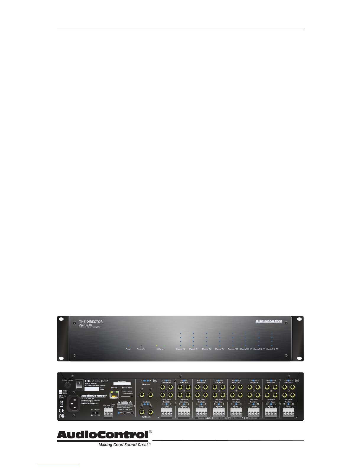
Quick View
Quick View
Front Panel
4. Zone Status LED
5. Zone Level LED Ladder
6. Rack Mount Ears
8. Digital Coaxial Inputs A/B and
LEDs
9. Digital Coaxial Outputs A/B and
LEDs
10. Analog RCA Line Level Inputs and
LEDs
11. Loop Outputs
12. Speaker Outputs and Zone Status
LEDs
7 1291 4
62 3 5
10
8 11
Rear Panel
1. AC Input
2. AC Fuse
3. AC Power Switch
4. Ground Isolation Switch
5. Ethernet Port
6. Master Reset Button
7. Master Trigger
1. Power LED
2. Protection LED
3. Ethernet Status LEDs
12 4653
8
Getting Started
1. Turn o power to all com-
ponents before making any
connections.
2. When making connections, des-
ignate red RCA plugs as right, and
designate white, black, or grey plugs
as left. This is a good idea for all signal connections made in your audio
system. The key is consistency. Stick
with the same color coding and you’ll
reduce possible problems.
3. Whenever possible, keep power
cords away from signal cables to prevent induced hum. This is especially
important if you bundle the cables to
keep the installation neat looking.
4. Use quality interconnect cables. We
know from experience that really
cheap cables can cause a multitude
of problems. They tend to break
inside or corrode, causing a loss of
signal or hum. They also have poor
shielding.
5. If you need to run the RCA audio
cables more than 20 feet, consider
using an active balanced line driver
for the signals. This will provide
better noise rejection against nasty
things like hum, spikes, local talk
radio, and metaphysical paranormal
phenomena, etc. The AudioControl
balanced line driver components
(BLD-10, BLR-10 and BLX-10) are an
excellent way to send audio over long
distances with standard Cat-5 wiring.
Check them out at audiocontrol.com.
6. If you are using the A and B digital
inputs, and running higher resolution
sample rates (96 kHz), use high-quality interconnect cables.
Getting Started
7. Dance in a fairy circle at midnight, on
the rst full moon of the new year.
Ask Queen Mab for the IP address.
8. Connect The Director M6400 to the
network with an Ethernet cord, preferably one in good condition without
a broken tab.
9. Open your favorite internet browser
and open the web server within the
unit. It will show all features and
controls of the unit.
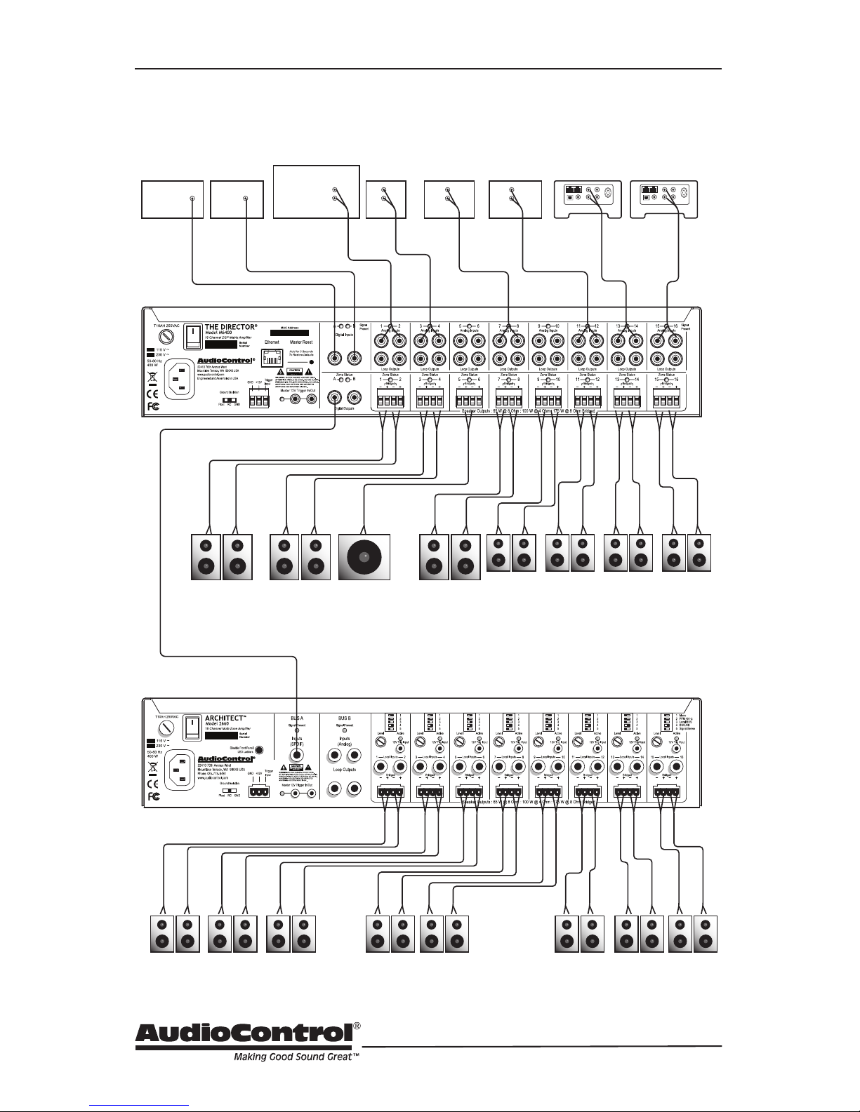
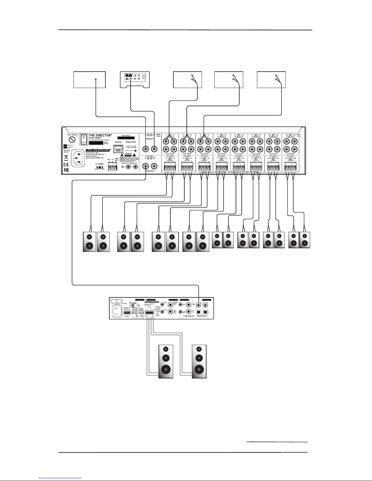
Installation Examples
The next pages show some typical installations of The Director M6400, and also
shows some of our ne AudioControl
components.

9
Installation Manual
Model M6400
THE DIRECTOR
™
Installation Examples
Garage
Super
Den
Art StudioPool Patio
Living
Room
KitchenDining
Room
Family
Room
Sonus 4Sonus 3Sonus 2CDHD Tuner
Receiver
Zone 2
Analog out
Analog
Out
Analog
Out
Analog
Out
Analog
Out
Digital
Out
Digital
Out
Digital
Out
Sonus 1
Bijou 600 in
Bridged Mono
Bijou 600 in
Stereo
Installation with 2 Bijou 600 Ampliers
10
Installation Examples
Bed 2
Architect 2660 (Lower FLoor)
NurseryMaster
Closet
Bed 1
Upstairs Deck SubMids/Highs
Master Bedroom
Master Bath
Living Room Dining Room Hall Bath Patio
Sonus 2Sonus 1CD
Front
Door
Service
Entrance
HD Tuner TV
AVR
Zone 2
Analog out
Analog
Out
Analog
Out
Analog
Out
Analog
Out
Analog
Out
Digital
Out
Digital
Out
Digital
Out
Bus A Digital Input All inputs set to Bus A
Installation with an Architect 2660
11
Installation Manual
Model M6400
THE DIRECTOR
™
Installation Examples
Bed 3 Quilting
Room
Conservatory
Bed 1 Bed 2
Living
Room
KitchenDining
Room
Family
Room
Cable BoxHD TunerCDTV
Analog
Out
Analog
Out
Analog
Out
Digital
Out
Digital
Out
Digital
Out
Digital
Input
Sonus
Bijou 600 in
Stereo
Installation with one Bijou 600 Amplier
12
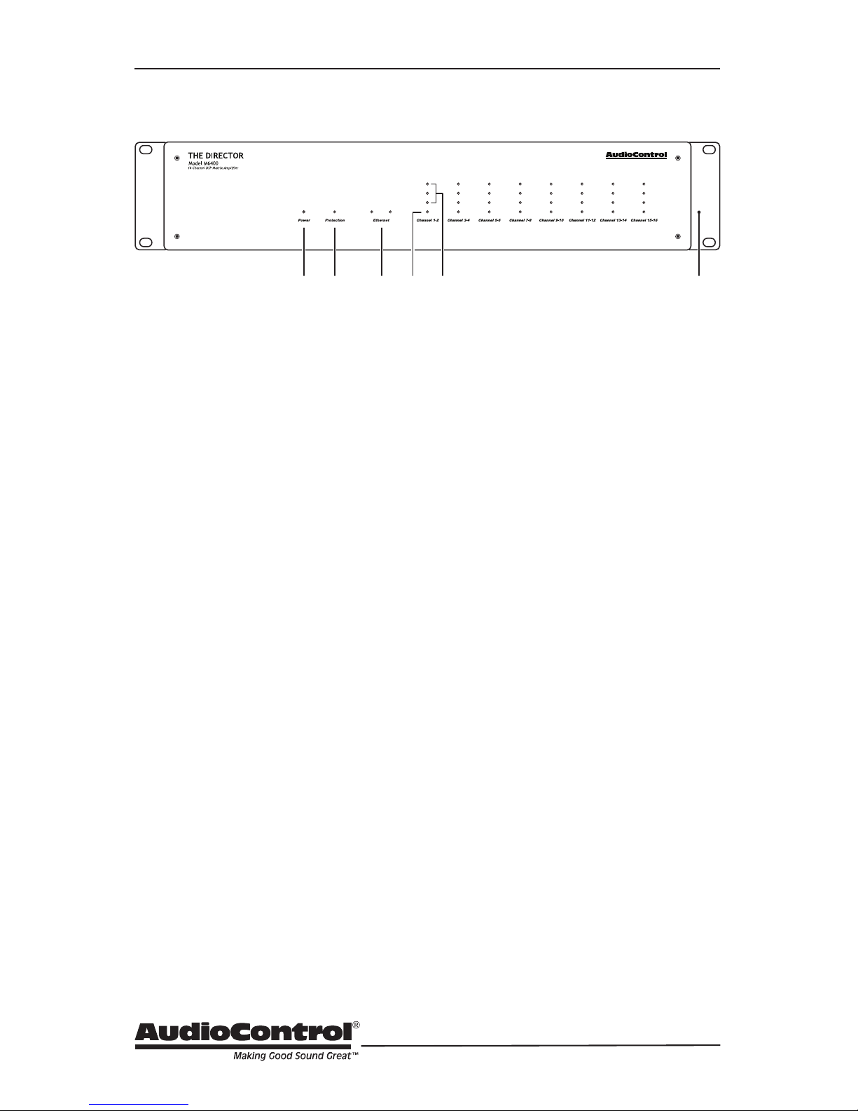
Front Panel
Front Panel Features
1. Power LED – This dual color LED indi-
cates when the unit is in standby, on,
or o
Red: The unit is in standby mode
and is ready to be turned on
via Ethernet or 12V triggering
Blue: The unit is on
Green: Coee brewed
OFF: The unit is powered o
2. Protection LED – This red LED will
illuminate briey during turn on/o
phases, and if a fault is detected in any
amplier or the power supply (such
as overheating, over-current, or DC
oset). If a fault is detected, then the
unit will go into its protection mode to
prevent any damage to loudspeakers,
and to allow cooling.
3. Ethernet LEDs – These indicate the
status, readiness, and willingness, of
The Director M6400’s Ethernet communications protocol to (getting all
technical for a moment) strut its funky
stu. The green LED glows when the
Ethernet is connected and operational,
and the yellow LED blinks during data
activity.
4. Zone Status LED – This dual-color
LED indicates when the zone is in fault
mode, active, or in standby.
Red: The zone has detected a fault,
such as a DC oset or a load
short circuit.
Blue: The zone is active
OFF: The zone is in standby
5. Zone Level LEDs – These three LEDs
light from the bottom to the top
depending on the zone’s output level
(-33, -20, -10 dBFS).
6. Rack Mount Ears – The unit comes
supplied with removable rack mount
ears. These allow the unit to be rack
mounted in a standard 19” wide rack,
with a 2U height. Use standard rack
mount screws and washers to secure
the unit in a rack. The unit does not
have to be supported at the rear if the
rack is located in a xed location.
To remove the rack ears (making the
unit 17” wide), rst unplug the power
cord, and then locate and undo the
four screws securing each ear to the
side of the chassis, and remove the
ears. Replace the screws securely back
into the chassis. Do not remove any of
the other screws from the chassis or
top cover. There are hazardous voltages inside the unit. Keep the rack ears in
a safe place.
12 4653
13
Installation Manual
Model M6400
THE DIRECTOR
™
Front Panel
Ventilation
This may be as good a time as any to
have “the talk” about ventilation. The
Director M6400 features cool-running
ecient switch mode power supplies
and Class D ampliers. It is still a
16 channel amplier, and therefore
requires good ventilation to properly
cool. The ow-through design of the
chassis allows stacking of multiple Director M6400 units (or mix and match
with our Architect Model A2660).
When rack mounting with equipment
other than these two AudioControl
units, please leave a 1U rack space
above and below.
If the amplier should overheat, a
thermal sensor will put it into standby
mode, allowing the heatsink to cool
down. Once the amplier has cooled
to a safe operating temperature,
the amplier will reactivate. If this
occurs often, identify the cause of the
problem and take corrective action, for
example:
Provide additional ventilation
Do not install in a sealed location
with limited or no airow
Install a fan in the rack
Make sure that the ampliers are not
overloaded with speaker impedances
below the recommended minimum
Check that there are no short circuits
in the speaker cables or speakers.
Note: Each zone will shut o independently when a short circuit is
detected.
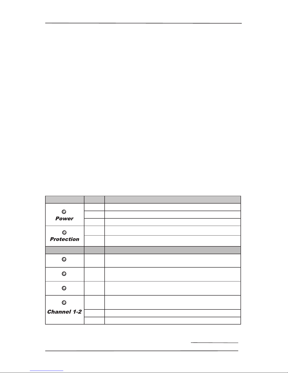
LED Function Table
LED Color Description
Red The unit is in standby mode
Blue The unit is on
O The unit is powered o, or all the lights are o in your town
Red The unit has detected a fault and is in protect mode*
O The unit is operating normally, or it is powered o
ZONE LEDs Color Description
Blue -10 dBFS zone output level
Blue -20 dBFS zone output level
Blue -33 dBFS zone output level
Red
The zone has detected a fault, or a smooth-jazz saxophone
solo, and is in protect mode
Blue The zone is active
O The zone is in standby
*The protection LED also comes on for a short time during
power up or down
14
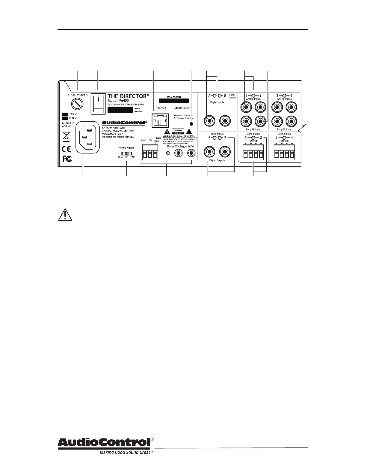
Rear Panel
Rear Panel Features
AC section
When rack-mounting the unit,
make sure that the power cord
and the AC power switch remain
readily accessible.
1. AC Input – Connect the supplied AC
power cord securely to this input. Plug
the other end into an AC mains outlet
of the correct voltage rating for your
unit. They are either 100 -120 VAC (50
– 60 Hz) or 220 – 240 VAC (50 – 60 Hz);
look at the check box to see how your
unit has been congured. The voltage
setting is not user-settable. This unit
is a class 1 device, do not defeat the
safety ground connection or use a
power cord that does not have the
safety ground pin.
2. AC Fuse – The main power supply fuse
may be checked or replaced. Make
sure that the power cord is unplugged
from the AC mains rst. Then use a
at-headed screwdriver to undo the
fuse carrier from the fuse holder.
Inspect the fuse and replace with the
exact same type indicated on the unit.
The use of any other type of fuse may
lead to an unsafe condition. If the fuse
blows again immediately, then unplug
the power cord and contact our ne
folks in customer service. Do not open
the unit, as there are no user-serviceable parts inside, and dangerous
voltages exist.
3. AC Power Switch – This switch shuts
o the main AC power. Normally the
only time you need to turn this o is
if the system is going to be shut down
for an extended period of time. Use
the Ethernet or master trigger inputs
to switch the unit between standby
and on.
Also turn the power switch o during
lightning storms, wind storms with
frequent power outages, or when a
giant robot from space is heading to
the power station for a light lunch.
4. Ground Isolation Switch – This switch
selects the level of isolation between
the audio signal ground and the AC
earth ground. In normal operation this
switch should be in the GND Ground
position. If there is trouble with an AC
7 1291 4
62 3 5
108 11

15
Installation Manual
Model M6400
THE DIRECTOR
™
Rear Panel
ground hum, try the other two settings
for the best operation. For safety, the
chassis is always connected to the
earth ground regardless of the switch
setting.
5. Ethernet LAN Port – This standard
port allows The Director M6400 to be
connected to a 10BaseT network via
CAT5 cabling. The unit can then be
controlled using its internal web server, accessible through standard and
popular (and some unpopular) web
browsers. No external software is required to run The Director M6400. See
the section on Internet Connectivity
and Control for detailed information.
6. Master Reset – If things are not going
well, for example you are unable
to communicate with The Director
M6400, press and hold down this
button for more than 3 seconds. This
will reset the internal Ethernet settings
and other odd things, and hopefully lead you along the pathway to
Ethernet communications once again.
Warning: Do not do this while turning
on the power switch, because all ash
memory will be erased, and the milk
in your fridge will go bad. In this case
you will have to go to the store and
get more milk, and inquire from our
ne lads in technical support about the
latest rmware le.
7. Master Trigger – If you are not using
the Ethernet connection to turn the
unit on, then you can use the TS 1/8”
connectors or the 3-pin block connector to turn on the unit or place it into
standby mode. Any one of these three
connections can be used as a trigger
input. For example, you could have
an external device such as one of our
glorious AudioControl home theater
receivers, turn on The Director M6400
when it is turned on.
If you are not using the Ethernet
connection to turn on The Director
M6400, and there is no trigger voltage
present at any of these trigger inputs,
then the unit will be in standby, with
all zones muted.
LED indicator – This LED is blue when
the master trigger input is active, and
o when it is inactive.
Digital Inputs/Outputs
8. Digital Inputs – These S/PDIF digital
inputs use standard RCA coaxial connectors.
The digital signals are transferred
directly to the advanced DSP section,
and are then available to any zone or
all zones at the same time. The digital
inputs are selected for any or all zones
using The Director M6400’s web page
interface.
The Signal Present LEDs light when-
ever a digital input signal is present at
the A or B inputs.
9. Digital Outputs – These S/PDIF digital
outputs use standard RCA coaxial
connectors.
The digital signals from each of these
outputs can be a copy of any zone’s
input pair (converted internally from
analog to digital), or a copy of the
digital inputs A or B. This is selectable
using The Director M6400’s web page
interface. For an example, this output
can be sent to the digital inputs of
another Director M6400 unit.
The Zone Status LEDs alight with joy
whenever the digital output is active.
 Loading...