


Home Theater
s y s t e m
ConCert avr-4
Home Theater Surround Sound Receiver
User Functionality Manual
For those who consider
perfection possible
AudioControl
®
®
22410 70th Avenue West • Seattle, WA 98043 USA
Phone 425-775-8461 • Fax 425-778-3166
www.audiocontrol.com
©2012. All Rights Reserved

Home Theater
s y s t e m
Home Theater Surround Sound Receiver
User Functionality Manual
For those who consider
perfection possible
®
®
22410 70th Avenue West • Seattle, WA 98043 USA
Phone 425-775-8461 • Fax 425-778-3166
www.audiocontrol.com
©2012. All Rights Reserved

This page was intentionally left blank. Please enjoy it!
4
®
Phone 425-775-8461 • Fax 425-778-3166

table of Contents
IntroduCtIon . . . . . . . . . . . . . . . . . . . . . . . . . . . . . . . . . . . . . . . . . . . . . . .7
Key features and HIgHlIgHts . . . . . . . . . . . . . . . . . . . . . . . . . . . . . . . . . . 9
a guIded tour of tHe ConCert avr-4
Front Panel Features .................................12
Rear Panel Features .................................13
set-up & ConfIguratIon
Unit Placement .....................................15
Speaker Considerations and Placement ..................15
Power Wiring. . . . . . . . . . . . . . . . . . . . . . . . . . . . . . . . . . . . . . .16
Audio Connections ..................................16
Video Connections ..................................17
navIgatIng tHe set-up Menus’
Initial Display Configurations ..........................19
Input Configuration .................................21
General Setup ......................................24
Auto Setup ........................................25
Speaker Types ......................................27
Speaker Distance ...................................27
Speaker Levels .....................................28
Video Inputs .......................................28
Video Outputs ......................................28
Surround Modes ....................................30
Zone Settings ......................................31
Network ..........................................32
playIng audIo fIles vIa networK audIo & usb sourCes . . . . . . . . .33
autoMatIon IntegratIon . . . . . . . . . . . . . . . . . . . . . . . . . . . . . . . . . . . . .35
troublesHootIng . . . . . . . . . . . . . . . . . . . . . . . . . . . . . . . . . . . . . . . . . . .49
warranty . . . . . . . . . . . . . . . . . . . . . . . . . . . . . . . . . . . . . . . . . . . . . . . . .52
speCIfICatIons . . . . . . . . . . . . . . . . . . . . . . . . . . . . . . . . . . . . . . . . . . . . . .55
Phone 425-775-8461 • Fax 425-778-3166
®
5

Another page left intentionally blank.
6
®
Phone 425-775-8461 • www.audiocontrol.com

Greetings from the rainforest
On behalf of everyone at AudioControl we wanted to congratulate you
on your selection of the Concert AVR-4 Home Theater Surround Sound
Receiver. Whether this is your first venture into home theater or you are
long time seasoned audio veteran, you will truly enjoy the performance of
this product.
While there are many components involved in creating a truly awesome
home theater from room design, speaker placement, and ultimately system
calibration, selecting the proper products is always very critical. For that
reason AudioControl created the Concert AVR-4 to provide maximum
enjoyment and flexibility which all contribute to a truly awesome home
theater experience.
AudioControl’s passion for high quality, meticulous attention to detail and
professional sound heritage shows itself in the dozens of awards we have
won for our designs, products and service. This manual is designed to help
you get the most from your Concert AVR-4 home theater receiver. Even
though you’re dying to plug it in and start pushing buttons, please take
a little time to glance over this users guide and learn about the Concert
AVR-4. Any component that does as much as the Concert AVR-4,
deserves all the explanation it can get. Given the complicated nature of
the Concert AVR-4, we also recommend you visit our website for updates
to this manual. Continued technology changes/improvements will require
more information. (www.audiocontrol.com - click “Home Theater”)
IntroduCtIon
Enjoy the experience.
Your Friends At AudioControl
®
Phone 425-775-8461 • www.audiocontrol.com
7

8
®
Phone 425-775-8461 • www.audiocontrol.com

Key Features Of the Concert AVR-4
While the AudioControl Concert AVR-4 is equipped with a large number
of features and functions that were designed to maximize your theater experience, we wanted to draw your attention to a few that deserve extra attention. These will be the features you will want to mention to your friends,
family and co-workers to impress them when they ask you about the home
theater components you have auditioned.
3D Support
Your Concert AVR-4 is now equipped with the much requested Video
Bypass function. This allows you the option for HDMI video to bypass the
video scaler in your Concert AVR-4. This is done so that unaltered 3D
signals are delivered directly to your display device.
Video Bypass
Out of the box, the Concert AVR-4 is configured with the video bypass on.
This enables high definition and 3D HDMI video signals to pass through
directly to the display device, leaving the Concert AVR-4 to make good
sound better. With Video Bypass on, analog video inputs, such as component or composite, will still be passed through the scaler for upconversion
and output via HDMI. Please keep in mind that when the Concert AVR-4
is in Video Bypass mode, on screen volume overlays, audio mode changes,
base/treble adjustments etc…will not be displayed. Pressing “Menu” however will engage the video scaler and yield a menu screen to your display so
that you can make adjustments if necessary.
Key features and HIgHlIgHts
HDMI Inputs and Outputs
The Concert AVR-4 is equipped with 120 individual audio and video
inputs and outputs, including a large number of HDMI (High-Definition
Multimedia Interface) inputs and outputs. The new generation HDMI
inputs will allow the Concert AVR-4 to interface with Blu-Ray players, satellite and cable decoding boxes plus traditional DVD players that also have
HDMI connectors. HDMI is an uncompressed all digital interface standard
®
Phone 425-775-8461 • www.audiocontrol.com
used on many home theater products equipment. This format can be used for sending
audio, video, and control signals over short
distances. For longer runs, you can use the
AudioControl BVHD-20 which can extend
HDMI signals up to 150 feet via simple
CAT-5/6 cabling.
The dual HDMI outputs are assignable to
allow for priority switching via the display
9
Key features and HIgHlIgHts
device. Component, composite and S-Video signals can also be automatically upconverted, scaled to their maximum potential resolutions and
output through the HDMI ports.
Powerful and Cool Running Class H Amplication
The Concert AVR-4 utilizes AudioControl’s legendary Class H amplifier
topology to powerfully drive even the most demanding speaker systems.
Known for pristine sonics, cool operating temperatures, and ultra reliability,
this highly efficient amplifier design literally “sips” current, which helps it
to satisfy even the “greenest” of customers. Despite it’s minimal current
draw, the Class H design is powerful enough to drive 120 watts per channel
(840 watts total), with all channels being driven into 8 ohms. The Concert
AVR-4 also has the additional ability of driving into lower impedance’s
when necessary.
Dolby™ Volume
A constant annoyance for home theater users has been the significant
differences in volume levels as you switch between channels or sources on
your televisions and in your home entertainment systems. Variances in volume levels in DVD and Blu-ray Disc™, digital music files, compact discs,
and broadcast entertainment programming each compound the problem,
forcing you to reach for the remote controls to adjust. Dolby Volume lets
you select a preferred listening level and enjoy all of your entertainment
sources at the same volume level. For complete information on Dolby Volume, go to
www.dolby.com/consumer/technology/dolby-volume-audiocontrol.html
10
Multiple Surround Sound Formats
The Concert AVR-4 supports the latest surround codecs of Dolby True
HD and DTS-HD Master along with traditional formats of Dolby Digital
5.0 and DTS High Resolution. A powerful 32 bit DSP processor enables
the Concert AVR-4 to decode all current discrete surround digital formats
available for 5.1, 6.1 and 7.1. In addition your Concert AVR-4 has the capabilities to process two channel signals using Dolby Pro Logic II, Pro Logic
IIx and DTS Neo to provide multi-channel output.
Multi-Zone Operations For 2nd and 3rd Zones
Since we know your audio and experiences may extend beyond one room,
the Concert AVR-4 is equipped with outputs for secondary and tertiary
zones. This means you could be enjoying your home theater in one room
and another member of the family could be listening to their favorite CD in
another room while your “crazy uncle” could have independent volume in
a third room. The Second Zone is also equipped with a video output so you
can expand your video options even more.
®
Phone 425-775-8461 • www.audiocontrol.com

Key features and HIgHlIgHts
Inputs For Networked Audio and USB Sources
The Concert AVR-4 is designed to operate with most of today’s traditional
source units, like CD and DVD players. Additionally it can receive audio
signals over a computer network via an Ethernet input and or from a USB
source. You will want to contact a professional audio integrator for more
information on properly using these functions.
Extensive Automation Integration
An automation system is what really pulls most high-end home theaters
together. It puts the full power of the system at your fingertips. While
the Concert AVR-4 will operate with a number of IR remote controls
(sold separately), it is equipped with a dedicated RS-232 control (labeled
“Control”) and an extensive command library to control all aspects of the
Concert AVR-4. Using this port requires a fair amount of programming
and automation skills which are typically best done by professional custom
installations companies. Check out the AudioControl dealer locator on our
web site for more info: www.audiocontrol.com
We Want to Hear From You
Before you get too entrenched in the features of your Concert AVR-4, we
encourage you to take a moment and visit the AudioControl web site at
www.audiocontrolregistration.com and register your new Concert AVR-
4. It allows us to keep a record of your purchase of the Concert AVR-4.
Needless to say when you are in the pleasure business like we are, we love
to hear from our customers so feel free to include some comments. You
will also want to keep you own record of the serial number and put your
sales receipt or invoice in a safe place. This is very important in the unlikely event that the Concert AVR-4 needs to be serviced or for proof of
ownership if somebody takes a fancy to your theater system in the middle
of the night. Insurance companies have no imagination when it comes to
components like the Concert AVR-4 being part of the theater system. This
concludes the “gentle reminder” section of this manual.
Award-Winning Quality
The Concert AVR-4, like all AudioControl Perfection Theater components, is backed with a comprehensive five-year parts and labor warranty.
This comes from a company that has been designing and manufactur-
ing performance audio components in the USA since 1977.
Phone 425-775-8461 • www.audiocontrol.com
®
11
guIded tour of tHe ConCert avr-4
u
v w yx z
w
~
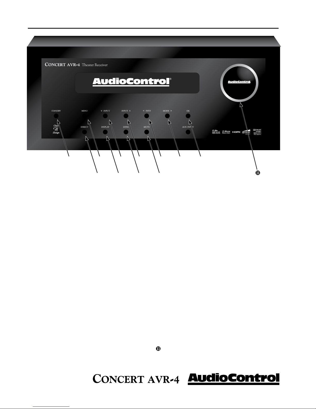
Front Panel Features
u STANDBY - The switch serves to “wake up”
your Concert AVR-4, provided the main power
switch, located on the rear panel, is turned “On”.
v MENU - Pressing this button will allows ac-
cess to the Set-Up Menu functions of the Concert AVR-4.
w INPUT (Up and Down arrows) - These
buttons allow the user to select an audio and
video source for playback or scroll through the
OSD (On-Screen Display).
x INFO - User can select the information that
appears on the display of the Concert AVR-4 and
also is used in navigating the OSD (On-Screen
Display).
y MODE - User can select between Stereo and
surround modes that are available for the source
unit and also is used in navigating through the
OSD (On-Screen Display).
z SELECT - Used in conjunction with the
Set-up Menu function, this button allows you to
enter selections you have made.
{|}
{ MUTE - Need to answer the phone, but still
keep an eye on the TV? Just press the Mute button to turn off the sound. Press it again and the
audio gracefully ramps back up to where you were
so rudely interrupted.
| ZONE - Allows user to select between the
Main Zone, Zone 2, and Zone 3
} DISPLAY - This cool blue display allows you
to see the basic functions of your Concert AVR-
4. It is important that you have an external
display device connected to one of the rear video
connectors for complete viewing of all menus
during set-up.
~ DIRECT - When using two-channel analog
inputs, this button defeats all digital signal processing and directs the two-channel analog input
from the selected source to the front outputs. Use
this button when you want to do some serious
quality two-channel listening.
MASTER VOLUME CONTROL KNOB -
This nice polished knob lets you adjust the volume
in selected zones (Main, Zone 2, and Zone 3).
12
®
Phone 425-775-8461 • www.audiocontrol.com
guIded tour of tHe ConCert avr-4
u
v
w
x
y
z ~
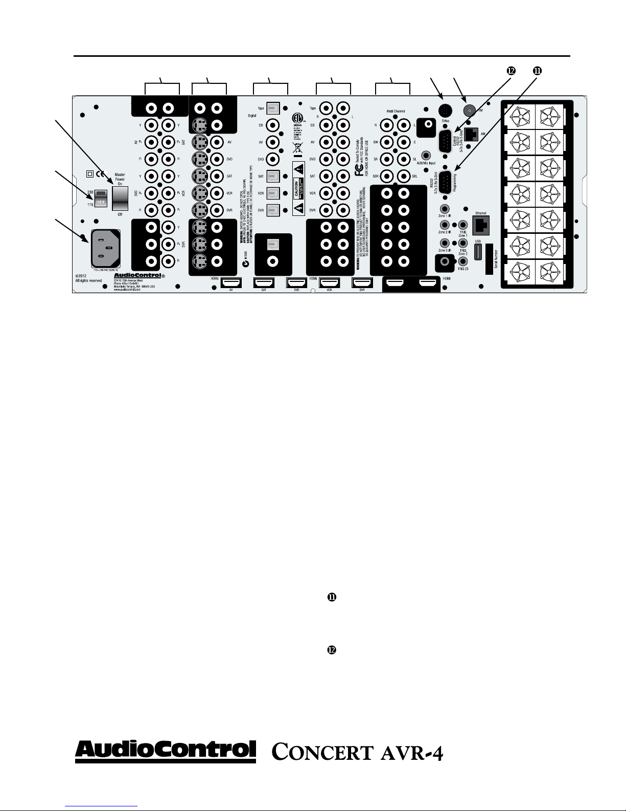
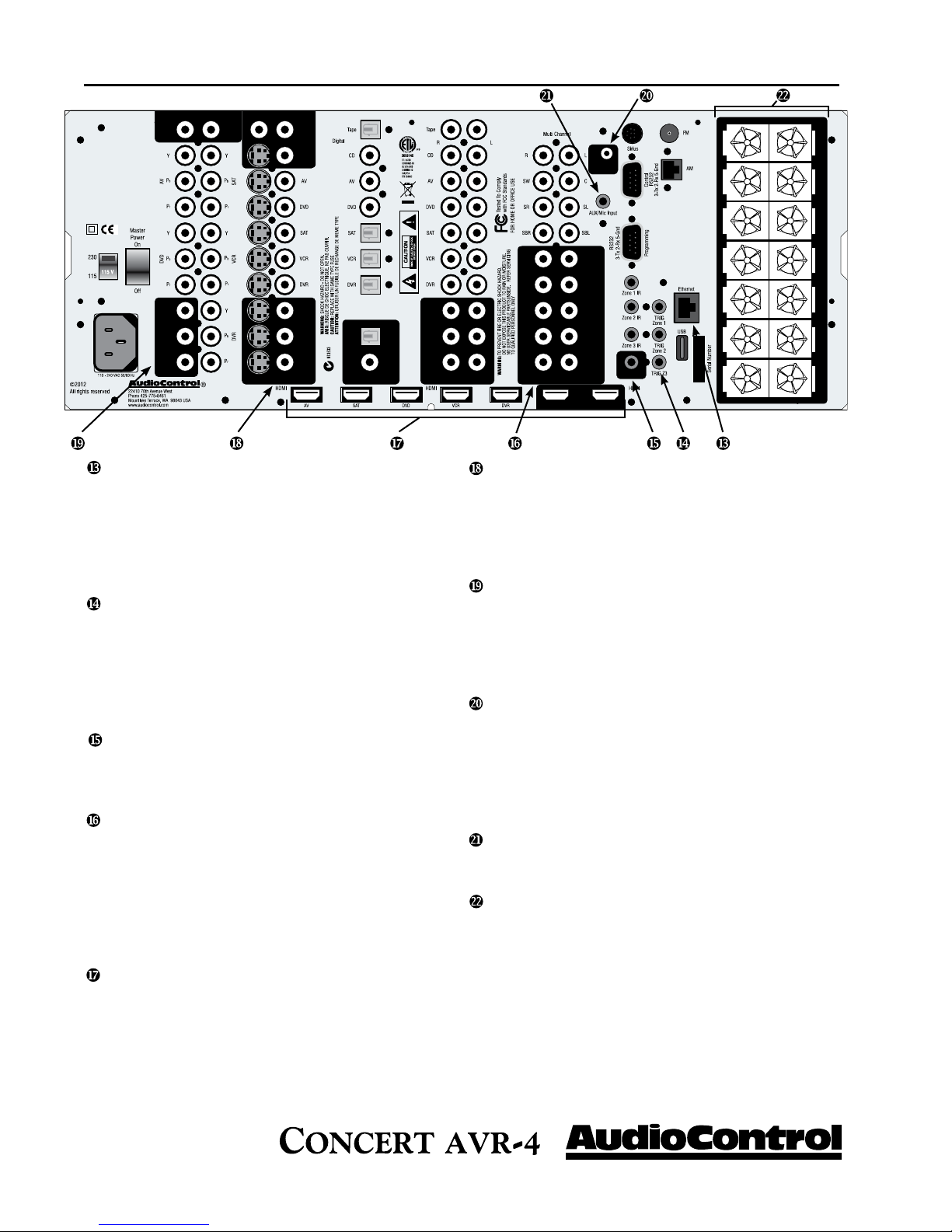
Rear Panel Features
u MAIN POWER SWITCH - The only time to
turn OFF the Concert AVR-4 with this button is
when the system will not be used for some time. Normally this button is left On and the Concert AVR-4
is “woken up” via the “Standby” switch on the front
panel, via an optional remote control or through an
automation system. When this switch is turned off,
you cannot turn the Concert AVR-4 On or Off via
any other method.
v VOLTAGE SELECTION - The Concert AVR-
4 is designed to operate with either 110-120V volt
or 220-240V line voltages. You will want to set this
switch to match up with your local power voltages.
w POWER CONNECTION - All good AC power
flows in here.
x ZONE 3 AUDIO OUTPUTS - These audio only
outputs can feed an external amplifier while sharing
the same source as Zone 2 but allow for independent
volume control of the outputs.
y ZONE 2 AUDIO/VIDEO OUTPUTS - These
second zone outputs enable listening and viewing a
source independently of the main theater system.
z DIGITAL AUDIO CONNECTIONS - The
Concert AVR-4 features assignable coaxial and
optical digital audio inputs and outputs. While we
have labeled them with the names of typical source
units, these connections as assignable via the internal
menu’s
{
{ ANALOG AUDIO INPUTS AND OUTPUTS
- Connect the appropriate two channel stereo outputs
and inputs from your source units here.
| MULTI-CHANNEL DVD-A/SACD INPUTS -
Newer multi-channel Blu-Ray and DVD players can
give you superb music audio quality in full surround.
These players feature a surround decoder built into
them and output analog multichannels. The Multichannel inputs on the Concert AVR-4 bypass all
digital circuitry and connect the player to the amplifiers with only a volume control in the path.
} SIRIUS RADIO INPUT - The Concert AVR-4
is designed for use with the “SiriusConnect™ Home
Tuner” package (sold separately) which should be
connected to this input via the cable supplied in that
package.
~ ANTENNA CONNECTIONS - These inputs
should be connected to the AM and FM antennas
that are supplied with your Concert AVR-4. For
optimum reception you may want to consider a roof
mounted external antenna.
RS-232 PROGRAMMING PORT - It is also
used when updating the internal Concert AVR-4
firmware programming. Contact AudioControl for
more information.
CONTROL PORT - Use this connection to control the Maestro M4 with an automation system.
|
}
Phone 425-775-8461 • www.audiocontrol.com
®
13
guIded tour of tHe ConCeret avr-4
NETWORKED AND USB AUDIO INPUTS -
Your Concert AVR-4 has the ability to accept audio
files via an Ethernet connection or from a USB mass
storage device. This usage requires some expertise
in the area of computer networks so please refer to
page 33 or your AudioControl dealer for the proper
applications.
12 VOLT TRIGGER OUTPUTS - These three
outputs provide a +12 volt signal to control the power amplifiers, source units, video projector, screens
and curtains in the theater. The Main Trigger output
is active whenever the Concert AVR-4 is turned on;
the Video Trigger 2 is active whenever a video source
is selected.
IR (INFRARED) INPUTS AND OUTPUTS -
These jacks enable use of external IR sensors and
emitters for installations where it is not desirable (or
practical) to use the front panel IR.
MAIN AUDIO OUTPUTS - These RCA
outputs can feed external power amplifier(s), should
you choose to not use the amplifier built-in to your
Concert AVR-4. (Our customers tell us that our
AudioControl Savoy 7-channel amplifier works great
in these situations). Additionally the Concert AVR-4
has three subwoofer outputs that can feed signals to
active powered subwoofers.
HDMI INPUTS & OUTPUTS - These inputs
allow the Concert AVR-4 to accept digital audio and
video signals from source units equipped with HDMI
(High Definition Multimedia Interface) outputs.
Make sure your HDMI cables are properly inserted
into these connectors and that there no sharp “pulls”
on the cable that may prevent your connectors from
making a complete connection.
COMPOSITE AND S-VIDEO INPUTS &
OUTPUTS - These are for the video inputs and
outputs from your source units. If you are planning
on using the second zone video outputs, you should
ALWAYS connect a Composite video input from
each source.
COMPONENT VIDEO OUTPUT - When not
using the HDMI outputs connect these high quality
video outputs to your main video display device (i.e.
Projector, CRT, LCD, etc.) You will be pleased to
know that the Concert AVR-4 will convert Component, Composite and S-video signals to HDMI.
HEADPHONE CONNECTOR - This jack accepts an 1/8” input for using headphones with impedance ratings of 32 to 600 ohms. This jack is always
active and will not turn off the audio in the main
zones when a connector is inserted which allows it to
be used for remote installations. The main zones can
be muted via RS-232 serial commands if necessary.
AUX INPUT - This Aux input is used in conjunction with the auto-setup microphone. Additionally it
can also accept either analog or optical digital signals.
SPEAKER CONNECTIONS - These 5 way
binding posts allow you to connect the main speakers
for your two, five, or seven channel systems. Make
sure that the red (positive/+) wires are connected
to the red (positive/+) connector on the back if your
Concert AVR-4. Likewise the black (negative/-)
wires should be connected to the black (negative/-)
connectors on the back of the Concert AVR-4 to
maintain proper speaker polarity.
14
®
Phone 425-775-8461 • www.audiocontrol.com
Set-up and Conguration
Unit Placement
The Concert AVR-4 can be placed almost anywhere in your audio equipment stack. It is good practice to ensure that the equipment location is
properly ventilated and to make certain not to block the ventilation slots
on any other component. Avoid placing the Concert AVR-4 directly over
large power amplifiers or any other component that generates a lot of heat.
Unless they are made by AudioControl, some amplifiers can get pretty hot
and have big power transformers that can induce hum into other audio
components like Concert AVR-4.
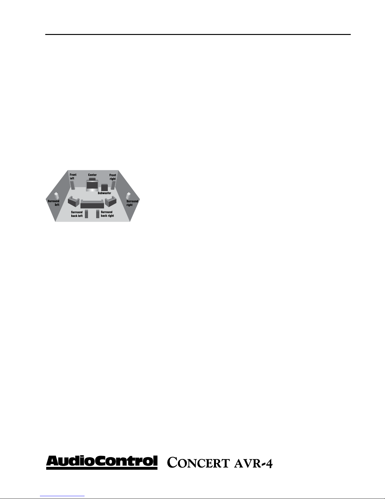
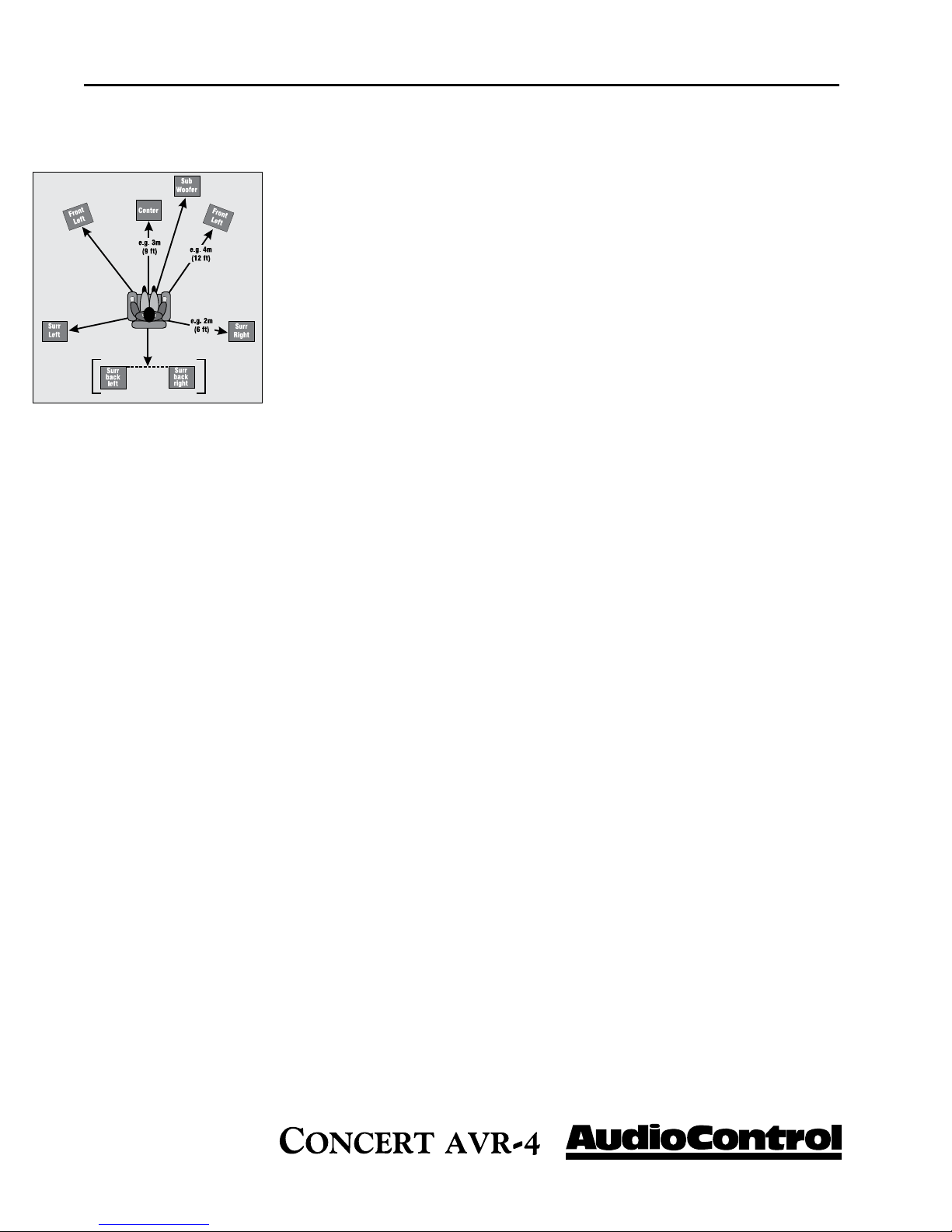
Front LCR (Left, Center, Right) Speakers
To present the most realistic sound stage, all three of the front speakers
must be tonally balanced. Ideally, these speakers should be identical
models. This ensures that the sound doesn’t change as it pans across
the screen. Place the speakers at the seated ear level. Whenever
possible, the three front speakers should also be placed at the same
horizontal level for best imaging.
set-up & ConfIguratIon
Side Surround Speakers
The surround speakers provide the reverberant, or ambient, sound effects
in a multi-channel theater audio system. These speakers should be placed
on the sidewalls approximately 36” above the seated ear height of the listeners. If you are using surround speakers, which have a dipole sound pattern, they should be mounted in-line with the main seating position. If the
surrounds are direct radiator, they should be just behind the main listening
seat.
Rear (Back) Surround Speakers
Some software provides extra channels that are used in 7.1 mode systems
to provide extra depth in the sound field. Place these speakers approximately 36” above the seated ear height of the listeners. Additionally, they
should be mounted close together on the rear wall of the theater facing the
screen.
Subwoofer(s)
The subwoofer is a large speaker that provides the bottom end “kick” in
the system. Depending on the size of your listening space, you may require
more than one subwoofer to get the bass volume levels that you desire.
Make certain you remember to include the size of all spaces that are open
to the theater in determining harmony subwoofers you need.
Phone 425-775-8461 • www.audiocontrol.com
®
15

set-up & ConfIguratIon
Connection Tips
Even if you’re an electronics veteran, this part may seem repetitive, but
some things can never be repeated too many times.
•Turnoffallcomponentsbeforemakinganyconnections.
•Whenmakingconnections,makesurethat“leftgoestoleft”and“right
goes to right.” The obvious and time-honored way to assure this is to assign
RED plugs to Right and WHITE/GREY/BLACK plugs to the left. Yellow is
usually used for video cables or digital audio connections.
•Whereverpossible,keeppowercordsawayfromsignalcables(i.e.,inputs
from disk players, VCRs, etc.) to prevent induced hum. Bundle all power
cords down one side of your equipment cabinet and all the signal cables
down the other.
•Usehighqualityinterconnectcables.We’renotgoingtogetintothedebate about whether $100 per meter interconnects improve the sound and
picture quality of your system. We do know from experience however that
really, REALLY cheap connections can cause problems.
INSTALL TIP *
•Don’tstandinabucketofwaterwhenworkingwithelectricity.
Power Wiring
Like many of today’s intelligent home electronics, the Concert AVR-4
should be plugged into an unswitched AC outlet so that it always has
power. This allows the RS-232 and remote control features to work even
when the Concert AVR-4 is in standby. We always recommend the use a
high quality surge protection device to keep all of your electronics safe from
the evils of spikes on power systems.
Audio Connections
Most of the sources will have two audio connections to the Concert AVR4; an analog 2-channel connection plus a digital audio connection. Whenever possible, connect both types of audio signals to the Concert AVR-4.
This will provide the digital audio signal necessary for high-quality digital
surround sound along with the analog audio for tape recording plus it
provides the necessary analog signals for the second and third zone audio
outputs.
Don’t worry if your satellite receiver has a coaxial digital output and the
Concert AVR-4 SAT input is optical. Refer to the advanced configuration
section on page 28 of this manual for more information regarding assigning
a digital input to the optical or coaxial connection.
16
®
Phone 425-775-8461 • www.audiocontrol.com
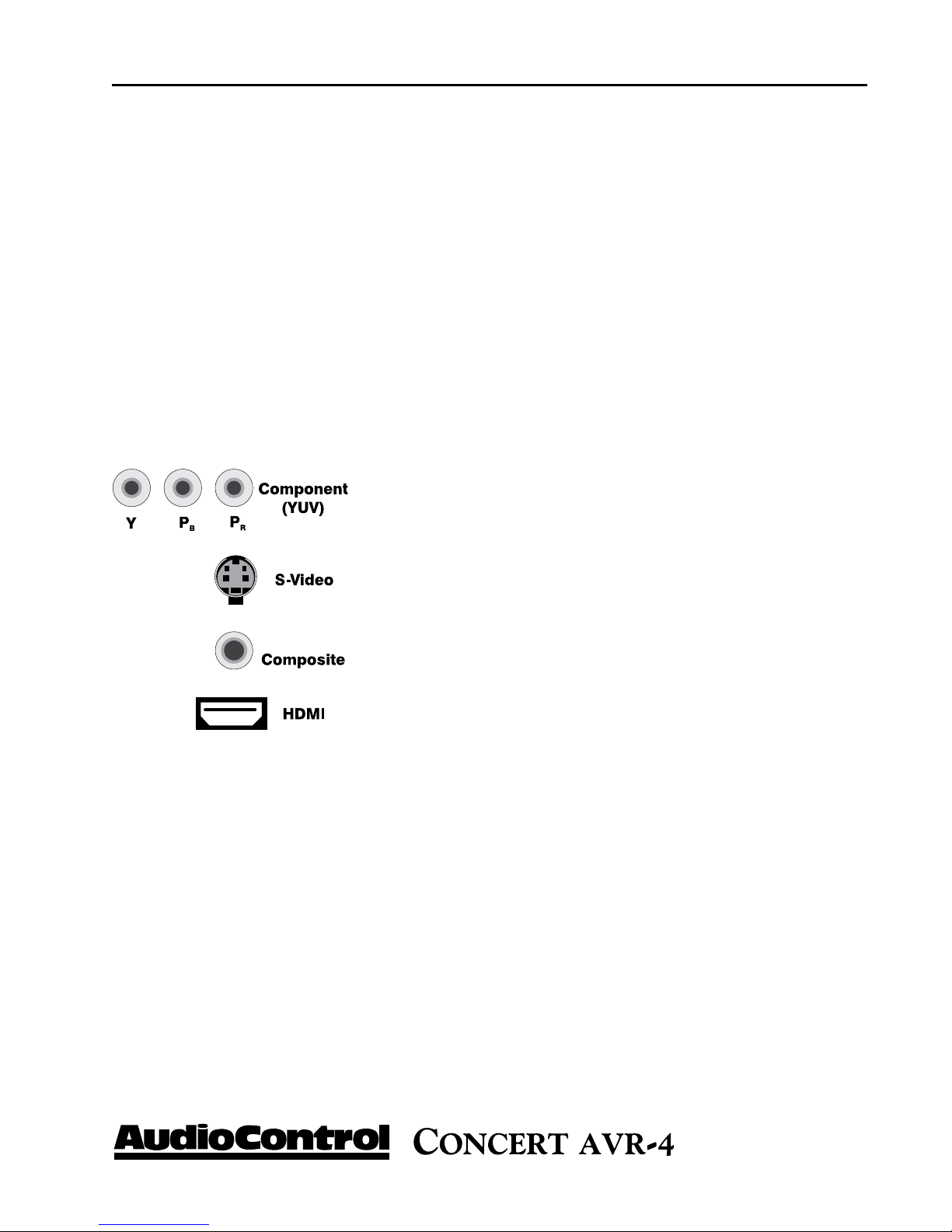
Video Connections
Types of video connections
set-up & ConfIguratIon
Multi-Channel Analog Audio
Audiophile surround recording formats such as SACD and DVD-A decode
the multi-channel signals directly within the Blu-Ray or DVD player. The
Concert AVR-4 features an eight channel direct-analog input for these
sources. These inputs bypass the digital circuitry in the Concert AVR-4
and are routed directly to the Main Amplifier outputs via an independent
volume control circuit. This ensures the highest possible audio quality for
this input.
Choosing your video
There are four video signal connection formats ranging from Good to Best;
Composite, S-Video, Component Video and HDMI digital video. Depending on the particular source unit you are using, you may have the option
of more than one of these video connections. Whenever possible connect as many as possible as the processor in your Concert
AVR-4 will identify the best format and route that to your main
HDMI, component or composite video outputs. Because of the
higher bandwidths involved with video signals, the quality of
the interconnect cables you choose is important especially with
HDMI. Video connections should always be made with cables
specifically designed for video. Don’t be tempted to grab some
extra audio RCA cables lying around. Without the proper 75
ohm cabling, your picture quality will suffer from smear, ghosting
or noise. It is always a good idea to make certain that the video
and audio signal cables are routed away from any power wiring.
Video Transcoding
To simplify your installations, the Concert AVR-4 provides video transcoding which routes the S-video, Composite signals, and Component video
signals to the HDMI outputs of your Concert AVR-4 regardless of video
bypass selection. As we mentioned before it is best to connect all analogue
INSTALL TIP *
and digital audio/video signals form your source units to your Concert
AVR-4 to allow proper use of the Main, Secondary, and third zones.
Phone 425-775-8461 • www.audiocontrol.com
®
17
set-up & ConfIguratIon
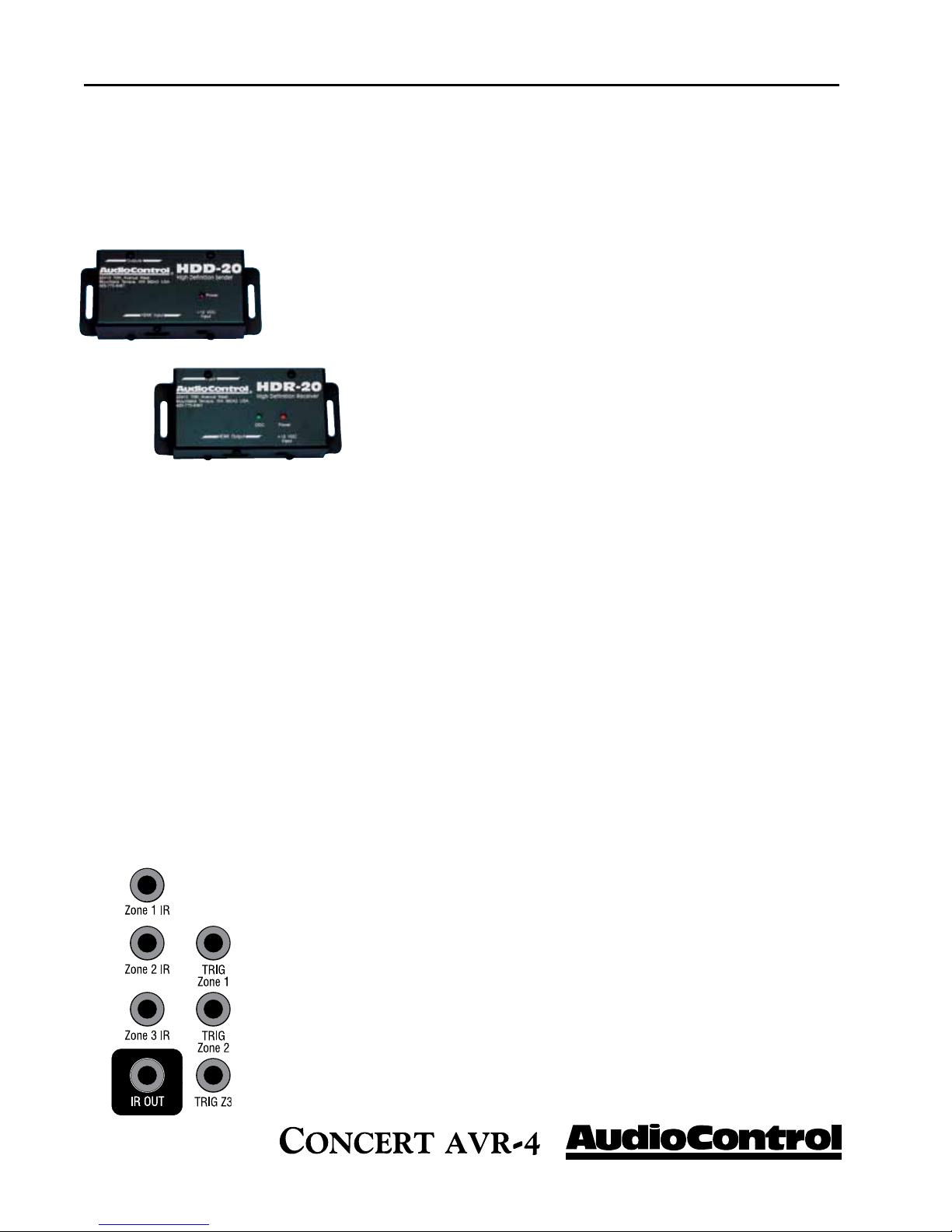
IR (Infra-red) Remote Control Connections
HDMI Signals
Your Concert AVR-4 is equipped with five discrete HDMI inputs and dual
assignable HDMI outputs. All the HDMI outputs are assignable to various
display devices, the signals on both will be the same as HDMI can only have
one processed video path.
Output 1 - Connect this to the display device located in your main zone or
theater.
Output 2 - Connect this to the display device located in your secondary zone.
Additionally, standard HDMI signals are only meant to be sent 20 to
30 feet before signal degradation or even dropout occurs. Therefore
we recommend you utilize a HDMI signal extension system like the
AudioControl BVHD-20, especially when using high bandwidth
signals like 1080p from Blu-Ray players or cable boxes.
We have equipped the Concert AVR-4 with a number Infrared (IR) inputs plus
an output to allow for maximum control flexibility with standard IR remote
controls (sold separately). This allows you to place the infrared receiver where
it can “see” the signal from the remote control when the equipment may be
hidden. The IR connections are designed for “modulated” signals and wired
for stereo or mono 3.5mm jacks with “Tip” being the modulated signal and
“Sleeve” being ground. The signals are compatible with third-party receivers
such as a Xantech No. 291-10.
Zone 1 IR - This is ideal for when the front panel of the Concert AVR-4 is
hidden away in some dark closet or equipment rack. To prevent the possibility of receiving multiple commands, when you connect an IR receiver to this
input, it will disable the front panel IR receiver.
Zone 2 IR - Allows for control of source and volume functions of Zone 2
Zone 3 IR - Allows for control of source and volume functions of Zone 3. You
will want to note that Zone 3 will always share audio sources with Zone 2.
IR Output - This output is an electrical combination of Zone 1, Zone 2, and
Zone 3 IR input signals and can be used as an IR repeater.
12V Trigger Connections
There are three stereo mini-jack 12 volt trigger outputs on the rear panel of the
Concert AVR-4 which are used to remotely control such things as the power
amplifier turn-on, projector power, screen automation. The jacks are designed
for 3.5mm mono connectors with “Tip” being the trigger output and “Sleeve”
being ground. Each jack is capable of outputting a 12V 70 mA switching signal.
18
®
Phone 425-775-8461 • www.audiocontrol.com
Setup Menus
INSTALL TIP *
navIgatIng tHe set-up Menus
This section of the manual discusses how to navigate the set-up menus of
your Concert AVR-4 home theater receiver. As you have probably determined by now, if you have the read the rest of this manual, the Concert
AVR-4 is an incredibly flexible and sophisticated processor that you can
literally “personalize” for use with your performance theater system. While
the set-up menus incorporate a number of default settings that we determined will work well with many theater systems, you will want to take the
time to go through each of these set-up screens and make the appropriate
adjustments to the settings. Once you have made the changes, you will not
have to change these again unless you make equipment or usage settings to
your system.
To get started and view these set-up menus it is very important that you
have one of the video outputs (Component, HDMI, composite, or S-Video)
of your Concert AVR-4 connected to your video display device (i.e. projector, flat panel, TV). This is absolutely necessary to see the set-up menus.
In the event you need to reset the output resolution and frame rate to the
factory settings, it is simply a matter of pressing and holding the
“SELECT” button for three seconds.
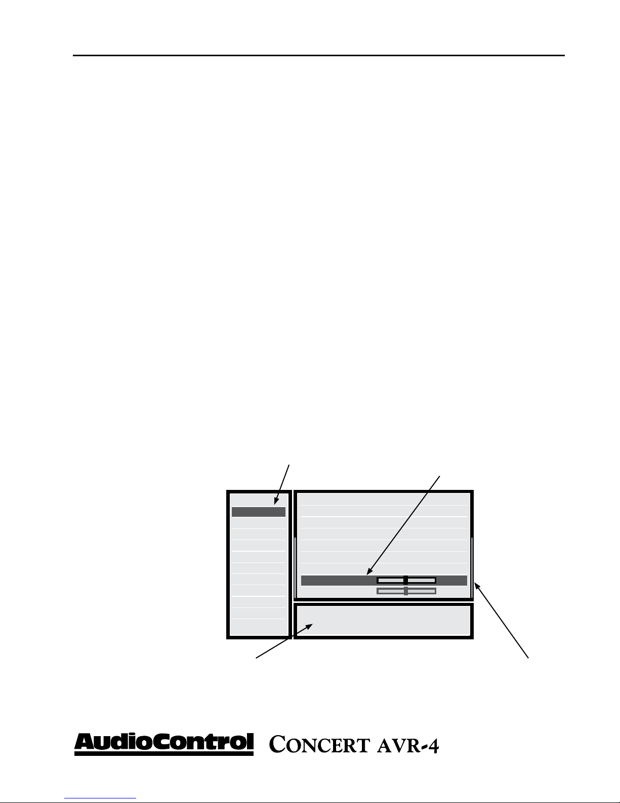
Menu Panel - The left-hand panel
lists the setup screens available for
adjustment. The selected menu is
highlighted with a dark green band.
Input Confi g
General Setup
Auto Setup
Spkr Types
Spkr Distance
Spkr Levels
Video Inputs
Video Outputs
Mode
Zone Settings
Network
Source Input :DVD
Incoming Format :Dolby digital
Incoming Sample Rate :45KHz Out : 48KHz
Incoming bitrate :192kbps
Dialnorm : -31dB
Video input :DVD
AudioCompression :Off
Balance 0dB
Bass 0dB
Adjust to compensate for an off-centre listening
position.
Help Screen - The lower
right-hand panel gives a
short help text for the feature being adjusted.
Adjustment Panel - The upper right-hand
panel lists the parameters you can change as
a user. The selected line is highlighted with
a dark green band. Lines that cannot be
selected are greyed-out.
Scroll Bars - These indicate
the position of the displayed
screen within longer menus.
Phone 425-775-8461 • www.audiocontrol.com
®
19

navIgatIng tHe set-up Menus
Initial Display Congurations
Your Concert AVR-4 has a default digital video output resolution of 720/60
and 525-line 60Hz NTSC for analogue video as these are the most common display resolutions. Needless to say you can change these in the setup menus if necessary. If your display device uses a different resolution, it
should synchronize automatically. However should you encounter an un-
If at any point you need
to reset the video output
resolution and frame rate to
the default setting, push and
hold the “Select” button for 3
seconds.
stable OSD (on screen display) you may need to make a resolution change.
Congurations For 1080p/24 Applications
The Concert AVR-4 supports both 1080p/24 fps (frames per second) and
the more commonly used 1080p/60 fps video formats. To properly utilize
the 1080p/24 format you will want to make sure that the source device (i.e.
Blu-ray player) and the display device (i.e. projector or TV) are both capable
of supporting this format. In the Video Output section of the Setup menus,
set the Output Resolution of your Concert AVR-4 to 1080p (not Preferred)
and make sure that the Frame Rate is set to follow input. Failure to do any
of the above could result in no image.
Navigating
Navigating the Set-Up Menus is a very simple process that can be done using the appropriate front panel controls on your Concert AVR-4 or by using
an IR remote control (sold separately) that incorporates the appropriate IR
codes.
1. Press the Menu button once to enter the Setup Menus. The word
“Menu” will appear on the display of your Concert AVR-4 and the actual
menu will appear on your display device.
2. Use the Input selection button “Input ∧” and “Input ∨” to navigate among
the menu’s and use the “< Info” and “Mode >” buttons to select appropriate
menu screen.
3. Press the “SELECT” button to select the menu options.
4. Press the Menu button anytime to exit the Menu screens and any setting
changes will be saved automatically.
20
®
Phone 425-775-8461 • www.audiocontrol.com
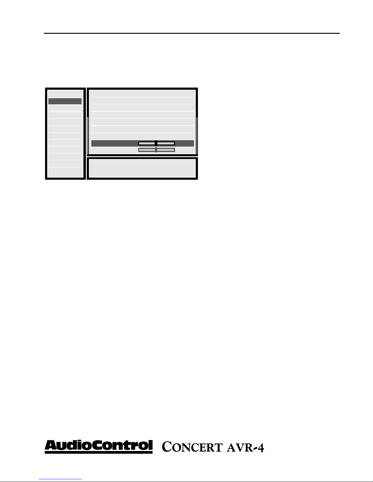
Input Conguration
Each input on your Concert AVR-4 has individual audio and video settings
that can be adjusted specifically for its use.
navIgatIng tHe set-up Menus
Input Confi g
General Setup
Auto Setup
Spkr Types
Spkr Distance
Spkr Levels
Video Inputs
Video Outputs
Mode
Zone Settings
Network
Source Input :DVD
Incoming Format :Dolby digital
Incoming Sample Rate :45KHz Out : 48KHz
Incoming bitrate :192kbps
Dialnorm : -31dB
Video input :DVD
AudioCompression :Off
Balance 0dB
Bass 0dB
Adjust to compensate for an off-centre listening
position.
the sound and the video picture. Highly compressed video signals such as
MPEG encoded satellite receivers and some DVD’s also suffer from this
problem. The Lip Sync setting delays the audio a small amount to allow the
video image to catch up.
MODE - Sets the initial audio decode mode for stereo sources on this input
EXT. MODE - Sets the initial audio decode mode for multi-channel digital
sources on this input.
TREBLE and BASS - Changes the bass and treble response for all speakers
when using this input. Very useful when you have a source unit that has
reduced frequency response due to the format (i.e. older VCR’s)
INPUT - Identifies the currently selected
source which settings are being displayed.
NAME - Specific name/label for this input
that will show on display device and OSD.
Very useful when you have more than one
source unit that may do similar functions
(i.e. 2 two Satellite receivers could be named
SAT1 and SAT2 accordingly)
LIP SYNC - Many video processors and
line multipliers cause a slight delay between
ROOM EQ - The Auto Speaker Set-Up in the Concert AVR-4 utilizes a
special algorithm that calculates many the major frequency resonance’s
that occur due to room acoustics and speaker locations and creates specific
equalization filters to offset this. This menu allows you to select whether
to engage the Room Equalization filter for each source. Options are “Not
Calculated”, “ON” or “OFF” with the default being “Off”.
INPUT TRIM - Selects the maximum analog signal for this input before
clipping. This setting should match the audio output of your source units
with the available settings being 0.5, 1, 2, and 4 volts RMS and the default
being 2 Volt. Source units with low output levels can benefit from being set
to higher output settings such as .5 or 1V.
®
Phone 425-775-8461 • www.audiocontrol.com
21

navIgatIng tHe set-up Menus
ume inconsistencies and improves audio frequency response at lower levels.
This feature is not available when using the Multi-channel audio or “Direct”
modes. For more information go to www.dolby.com/consumer/technology/dolby-
volume-works.html
source unit inputs irregardless of recording levels of content being played by
a particular source unit.
DV CALIB OFFSET - Dolby Volume provides a Calibration Offset parameter that compensates for speaker efficiencies and listening positions. If you
set the Speaker Levels on the Concert AVR-4 properly using an SPL meter
(like the AudioControl SA-3052) then you can leave this setting at 0.
DOLBY VOLUME - Selects whether Dolby is engaged for
this input with the options being “Off”, “Cinema” or “Music”
and the default being “Off”. Dolby Volume corrects for vol-
DOLBY LEVELLER - The setting options are “0” (minimum)
and “10” (maximum) with the default being “9”. This Dolby
Volume feature allows matching of quiet and loud sources of
SURROUND EX - When playing Dolby Digital EX encoded material, the
Concert AVR-4 gives you the option of selecting the Surround settings,
provided you have Surround Back loudspeakers connected. Setting options
are “Auto DD EX”, “Auto PLIIx” and “Manual”.
Auto DD EX - The Concert AVR-4 will automatically switch to Dolby Digital EX mode when a Dolby Digital EX bit stream is detected.
Auto PLIIx Movie - The Concert AVR-4 will automatically switch
to Pro Logic lIix Movie mode decoding when a Dolby Digital EX bit
stream.
Manual - If a Dolby Digital Ex bit stream is detected, the Concert
AVR-4 will treat it as a normal Dolby Digital signal. The EX or
Pro Logic lIix decode modes may be implemented by pressing the
“MODE” button.
STEREO MODE - If you are using an external subwoofer, and are listening to stereo (two channel) sources, either digital or analog system, you can
select to configure how the subwoofer receives it’s bass information. The
“Stereo Mode” functions are bypassed when using an analog source and you
have selected the “Stereo Direct” mode.
As Speaker Types - Your normal speaker configuration (as selected in
the “Spkr Types” menu) determines your subwoofer output.
Left/Right - Full frequency audio will be sent to your front left and
right speakers with no information going to the subwoofer.
22
®
Phone 425-775-8461 • www.audiocontrol.com

navIgatIng tHe setup Menus
Left/Right+Sub - Full frequency audio will be sent to your front left
and right speakers plus bass information is directed to your subwoofer
effectively duplicating the lower frequencies
Sat+Sub -
Full frequency audio signals are sent to your front left and
right speakers with the bass information being directed to only your
subwoofer. Your front speakers will only reproduce the upper frequencies.
SUB STEREO - If you have selected the “Left/Right+Sub” or “Sat+Sub”
setting in the “Stereo Mode” menu, then this setting adjusts the level of
the subwoofer when you are using a two-channel source.
BRIGHTNESS - This video setting adjusts the brightness for this input,
providing you are using a video equipped source unit.
CONTRAST - This video setting adjusts the contrast for this input.
COLOR - This video setting adjusts the color saturation for this input.
PICTURE MODE - The setting options are Video, Film, or Auto with the
default being Auto. The video processor in the Concert AVR-4 normally
automatically detects the original source type and properly sets the Video
mode or Film mode processing. Occasionally some source material is unable
to be interpreted properly by the processor, which may require a manual
adjustment.
EDGE ENHANCEMENT - This video feature sharpens the picture.
MOSQUITO N.R. - This video feature removes haziness that sometimes
appears around objects in a picture.
NOISE REDUCTION - This video feature removes random video noise
that may appear on the picture from a source unit.
BLOCK N.R. - This video feature removes block artifacts in overly compressed digital video signals
COMPONENT MODE - This mode allows you to configure the component video input of your source unit to properly match up with your display
device. Setting options are “Normal”, “RGsB” and “RG+Sync”.
Normal: Configures output for standard Component (YPbPr) analog
video.
RGsB: Configures for RGB analogue video with video “sync on
green”
RGB+Sync: Configures for RBG analogue video with sync on the
composite input for the selected source.
®
Phone 425-775-8461 • www.audiocontrol.com
23

navIgatIng tHe setup Menus
VIDEO SOURCE - Selects whether the video signal for this source is
detected automatically or locked to a particular signal type. Setting options
are “Auto”, “HDMI”, “Component”, “S-Video” or “Composite” with “Auto”
INSTALL TIP *
being the default. Note that the “Auto” setting will increase the switching
time, as it reviews all format options, therefore, it is recommended you select
the specific source format (i.e. HDMI) whenever possible.
AUDIO SOURCE - Allows you to select how the Concert AVR-4 receives
audio signals for this source. Settings options are “Remote”, “HDMI”, “Digital”, or “Analogue”.
General Setup
These menu screens display general information and system control
(Information Only)
Source Input: Displays the currently active audio source input.
Incoming Format: Displays format of digital audio stream
Input Confi g
General Setup
Auto Setup
Spkr Types
Spkr Distance
Spkr Levels
Video Inputs
Video Outputs
Mode
Zone Settings
Network
Incoming Sample Rate: Displays incoming sample rate of digital audio
stream, if present.
Source Input :DVD
Incoming Format :Analog Stereo
Incoming Sample Rate :96KHz Out : 96KHz
Incoming bitrate :
Dialnorm :
Video input :DVD
AudioCompression :Off
Balance 0dB
P L II Dimension 0
Adjust to compensate for an off-centre listening
General Settings for your unit.
position.
Audio Compression: Compressing the dynamic bandwidth of the audio can
be a good thing, especially for those late night action movie festivals. Compression increases the volume of quiet sections and and reduces the volume
of the louder sounds. These 3 options for this setting only apply to some
Dolby Digital or DTS soundtracks. As part of the general set up, this setting
applies to all inputs with digital audio streams that support this function and
is recalled each time the unit is powered up.
Incoming Bit Rate: Displays bit rate of digital audio
stream, if present.
Dialnorm: When a Dolby Digital audio stream is connected to this input this is the Dialogue Normalization
setting requested.
Video Input: The audio and video inputs on the Concert AVR-4 generally follow the source selected. This
setting allows you to temporarily override and change
the video settings so you can utilize a different video
source. Setting resets itself when source is change.
Off: Audio compression is not applied (default)
On: Whenever a soundtrack is received that supports this function the
On: Audio Compression is applied
On/Auto: Same as On (above), with the exception of Dolby TrueHD
On/Auto: soundtracks which supports an additional Auto on/off setting
Balance: Adjusts the left/right balance of the front outputs.
24
®
Phone 425-775-8461 • www.audiocontrol.com

navIgatIng tHe setup Menus
Dolby Prologic II Music Mode Settings
These setting apply to all two-channel inputs when PLII or PLIIx Music
mode is selected.
Dimension - Adjusts the depth of the front/rear sound stage. For
normal listening this should be set to +3. Setting options are –3 to
+3 with default setting being “0”.
Center Width - Determines how strongly the Pro Logic II decoder
processing creates the center channel image. Normally this signal
is fed only to the center channel speaker output, but if the center
speaker is set to “None” in the speaker setup, a phantom center
channel is created using the front left and right channels. Normally
this setting is left at +3.
Panorama - When the Panorama Mode is enabled, the front center
image is extended to include the rear surround speakers. This provides a more enveloping wrap-around effect.
INSTALL TIP *
Auto Setup
Digital Output Frequency -
Sets the sampling frequency of the audio Analogue-to-Digital converter. Settings options are 44.1/ 48 /96 kHz. Default is
96 kHz
Volume Adjustment - Allows you to set the step size for the volume control. Options are “Normal” (1 dB steps) or “Fine (.5 dB steps).
Maximum Volume - Limits the highest volume that the Concert AVR-4
will play. This is useful if you have speakers or amplifiers with limited power
handling abilities.
Max On Volume - This is the highest volume that the Concert AVR-4
will play when it is first switched on first turned. This prevents the Concert
AVR-4 from being turned on at shock volume levels from the last time you
were watching a good movie.
Your Concert AVR-4 is equipped with an Auto Setup feature that assists in
setting all of the essential speaker settings for your system, including which
speakers are present, types of speakers, crossover settings for the subwoofer,
sound level and distance compensation. It will also calculate basic room
equalization filters to offset frequency resonances caused by acoustics and
speaker placement. While there is no substitution for proper acoustical
treatments, speaker placement and theater calibration, the Auto Setup
Mode is useful for maximizing the acoustical performance of many theaters.
Phone 425-775-8461 • www.audiocontrol.com
®
25

navIgatIng tHe setup Menus
Microphone Positioning
The calibration microphone that comes with Concert AVR-4 is a designed
to be placed in the center of your theater in the main listening position
preferably at the same height as your head. Connect the microphone jack
to the “Aux” input on the rear of your Concert AVR-4.
INSTALL TIP *
Make sure you minimize any background sounds in the theater by turning
off any fans or noisy air conditioning systems, and close all doors and windows as outside sounds will negatively affect your measurement. Additionally if the microphone is positioned too close to the speakers this will result
in a signal Clipping error.
Run Auto Setup - In this menu, press the “Select” button on the
front panel and the Concert AVR-4 will begin generating test tones
out of each channel, a process that takes about two minutes. During
this process the AVR-4 identifies which speakers are being utilized in
the system and what the recommend system adjustments are, based
on the measurements.
Accept Setup - Once the Auto Setup has completed it’s testing, you
can select to accept the settings or reject them. Options are “No” or
“Yes”.
Auto Setup Progress - Displays a status summary of the Auto Setup
function and identifies any measurement errors during the testing
process. Options are “Calculating EQ” or “Completed Error”.
After running the test, this screen will display any system errors for
each speaker
Crossover Frequency - Based on the speaker measurements your Concert
AVR-4 processes, it will recommend a crossover frequency between your
subwoofers and your main speakers.
26
Not Present - Speaker was not detected – check connections if
necessary and move mic and rerun test.
Clipped - If you have highly efficient speakers or the microphone
is measuring over reflective sounds, this could result in a distorted
or “Clipped” measurments. Try repositioning the microphone and
running the test again.
Mic Too Close - This is generally a result of the microphone being too close to the speakers. Try repositioning the microphone
and running the Auto Setup test again.
®
Phone 425-775-8461 • www.audiocontrol.com

Speaker Types
This series of menus allows you to select the types of speakers that you will
be connecting to your Concert AVR-4. Please note that if you set all speakers to small then you must indicate in the menus below that a subwoofer
is present in the system. If not your speakers will be selected to Large. For
the purposes of setting the Concert AVR-4.
navIgatIng tHe set-up Menus
“Large” speaker is one that is capable of reproducing a full range (2020KHZ) audio signal. Use this setting when not using a subwoofer.
“Small” speaker is one that is not designed to reproduce deep bass
frequencies and is generally used with a subwoofer (i.e. typical Satellite speakers that typically can’t play below 80 Hz).
“None” If you do not have a speaker connected to an output (i.e. No
Subwoofer or Back Speakers) then set that speaker size to “None”.
“Subwoofer” Selects whether a subwoofer is present in your system.
Crossover Frequency - This controls the frequency at which bass is re-
directed from speaker channels set to “Small” and sent to the Subwoofer
outputs. This frequency is adjustable from 40 Hz to 150 Hz.
MCH Sub Levels - This adjusts the level of the subwoofer channels
when using an externally decoded multi-channel source (DVD-A, SACD,
HDMI, etc.) Most DVD players require a +10db compensation on the
subwoofer channel to maintain the correct balance levels with the main
channels. Setting options are “+10dB comp” or No comp”
USING CHANNELS 6 + 7 FOR - If your main speaker system consists
of only 5 main speakers and no Surround Back Left & Right speakers, you
can redirect signals from the unused amplifier channels to the front speakers or for Zone 2.
Speaker Distance
The Speaker Distance settings help the sound from each speaker arrive
at the listening seat at the same time. This provides a much more believable and immersive sound environment. Precise delay settings should
be done by a trained professional with audio test equipment such as the
AudioControl Iasys HT to measure the precise sound delay. You can get a
rough delay setting using Auto Set-up. Measure the distance from the center of a speaker to the seated ear position of the main listening seat. Write
each of these distances down and enter them into the Concert AVR-4 or
use auto setup.
Phone 425-775-8461 • www.audiocontrol.com
®
27
navIgatIng tHe set-up Menus
Speaker Levels
It is critical to properly match the levels from each speaker to achieve a
correct sound stage. The realism is totally lost if the footprints of a person
walking across the screen change in volume as they move from left to center to right. We strongly recommend using a test analyzer such as our Iasys
HT for this calibration. The levels are nearly impossible to judge by ear
alone. Though not as accurate as using the Iasys HT, you can use a sound
level meter for this adjustment.
With the internal test noise generator of the Concert AVR-4, adjust each
speaker for a sound pressure level (SPL) of 75 dB using a “slow” response
time on the SPL meter placed at the main listening position at ear height.
Video Inputs
Settings to optionally assign a video source to each of the normal “audio
only” inputs. The default for each of these settings is “None”. This is a
great way to listen to the ball game over the Internet Radio and watch it
over your normal video display device, though timing might be a little off.
Video Outputs
The Concert AVR-4 is not only a great sounding home theater processor
but it is also a very powerful video processor. To that extent it has a number
of video settings that need to be selected carefully to optimize your video
performance.
Zone 1 On Screen Display (OSD): While the set-up menus will
always show on your display device, you have the option of selecting
whether your Main Zone general settings (volume, subwoofer level,
etc.) show up on the bottom of the screen as an On Screen Display
(OSD). The options are “On” or “Off”.
Analog Output: Controls the output settings for the Composite and
S-Video analogue video outputs. You will want to note that these
outputs support display resolutions of 480i or 576i signals.
Analog Frame Rate: Controls the output frame rate for all Main
Zone analog video outputs.
Display Type: Options are 4:3 standard or 16:9 widescreen.
28
®
Phone 425-775-8461 • www.audiocontrol.com

INSTALL TIP *
Setting output resolution to match the
native resolution of
your display device
speeds up switch time
and will reduce the
potential for EDID
errors.
navIgatIng tHe set-up Menus
Output Switching: The HDMI outputs of the Concert AVR-4 are
completely assignable to match up with switching applications of the
theater system.
Auto-Priority Out 1/Out 2: This input senses which display
device is operating and gives priority to the selected HDMI output. If both HDMI outputs are being used, priority is given to the
device selected in this menu.
Output 1 or Output 2: Enables only selected output to operate.
Output 1 & 2: This setting allows both HDMI outputs to oper-
ate simultaneously. In this mode the maximum resolution for
both displays will be limited to the resolution of the lowest display
device.
Output 1 Resolution: Selects the output resolution for HDMI Output #1 with the options being a list of the available display devices or
“Preferred”. In the Preferred mode, this output matches the highest
preferred resolution of the display device. This setting is only effective if Output 1 is the only HDMI output being utilized.
Output 1 Frame Rate: Selects the output frame rate for HDMI Output #1 with the available options being displayed in the drop down
menu’s. Frame rates that are not supported by the display device
cannot be selected.
Lipsync 1 (Information Only): When this feature is supported by
the display device, this setting displays how much lip sync is applied
to HDMI Output 1.
Phone 425-775-8461 • www.audiocontrol.com
Output 2 Resolution: Selects the output resolution for HDMI
Output #2 with the options being available display devices or “Preferred”. In the Preferred mode, this output reflects the highest pre-
ferred resolution of the display device. This setting is only effective if
Output 2 is the only active HDMI output.
Output 2 Frame Rate: Selects the output frame rate for HDMI Output #2 with the available options being displayed in the drop down
menu’s. Frame rates that are not supported by the display device
cannot be selected.
Lipsync 2 (Information Only): When this feature is supported by
the display device, this setting displays how much lip sync is applied
to HDMI Output 2.
®
29

navIgatIng tHe set-up Menus
Surround Modes
This screen allows the user to select the specific decode and downmix
options that will be available to the listener in Stereo and Multi-channel
applications. The options for each format are “Yes” or “No” and are accessible by touching the “Mode” button on the front panel of your Maestro
M3.
Output 1 & 2 Resolution: Selects the output resolution when both
HDMI Outputs are being used with the options being available display devices or Best. In the Preferred mode, this output reflects the
highest preferred resolution of the display device.
Output 1 & 2 Frame Rate: This setting controls the frame rate
output of HDMI Output 1 & 2 with this setting only being active if
OUT 1 & 2 is the only selected HDMI output.
Lipsync 1 & 2 (Information Only): When this feature is supported
by the display device, this setting displays how much lip sync is applied to HDMI Output 1 & 2.
For more detailed
information on the
various Dolby and DTS
surround formats you
can visit www.dolby.com
or www.dts.com.
Formats Available For Stereo Sources: The following formats are
available when using media that contains either digital or analog
stereo signals (Dolby 2.0, digital PCM stereo, DTS 2.0 etc.)
Dolby Pro Logic - Original Dolby surround format that produces
five-channels of output from two-channel stereo material. Best used
when material is encoded in Dolby Pro Logic, otherwise it is recommended that you use Dolby Pro Logic II.
Dolby Pro Logic II - Advanced Dolby decoding process that produces five-channels of output when using two-channel stereo material.
This format also offers three different modes; Movie, Music, Matrix,
and Game which provide various enhancements depending upon the
source materials.
Dolby Pro Logic IIx - This Dolby format produces seven-channels
of output when using two-channel stereo material and allows you
to take better advantage of systems that utilize a 7.1 speaker system.
Like Dolby Pro Logic II, this format also offers three different modes;
Movie, Music, and Game for additional enhancement.
DTS Neo: 6 - This DTS based format outputs six channels of audio
based when using two-channel stereo material. This format also offers two different modes, Cinema and Music which provide various
enhancements depending upon the source materials.
30
®
Phone 425-775-8461 • www.audiocontrol.com

Zone Settings
This menu allows you select the audio and video control and volume settings for Zone 2 and Zone 3. You will want to note that the Zone 2 and
Zone 3 always share the same audio source.
navIgatIng tHe set-up Menus
Zone 2/3 Input - Selects the analog audio to be used for Zone 2 and
Zone 3.
Zone 2 Video Output - Selects the analog video to be used for Zone
2.
Zone 2 Status - Displays current status at Zone 2 with options being
“Standby” or “On”
Zone 2 Volume -
Displays current volume level in Zone 2.
Zone 2 Maximum Volume - Selects the maximum volume setting
for Zone 2.
Zone 2 Fixed Volume - Allows the Zone 2 volume to be fixed at the
current volume level.
Zone 2 Max On Volume - Selects the maximum volume level for
Zone 2 when the Concert AVR-4 is powered on or comes out of
stand-by mode.
Zone 3 Status - Displays current status at Zone 3 with options being
“Standby” or “On”
Zone 3 Volume - Displays current volume level in Zone 3.
Zone 3 Maximum Volume - Selects the maximum volume setting
for Zone 3.
Zone 3 Fixed Volume - Allows the Zone 3 volume to be fixed at the
current volume level.
Zone 3 Max On Volume - Selects the maximum volume level for
Zone 3 when the Concert AVR-4 is powered on or comes out of
stand-by mode.
Phone 425-775-8461 • www.audiocontrol.com
Standby - Selects what parts of the Concert AVR-4 turn-on and off
when a Standby command is received via the Zone 2 IR port. Options are “Local Only” or “All Off”.
®
31

playIng audIo fIles vIa networK audIo or usb
Network Settings
Your Concert AVR-4 has the ability of playing Internet radio stations as
well as music stored on a network storage device like a PC or USB flash
drive. Typically the computer network may use DHCP to automatically
make the necessary networks settings although the Concert AVR-4 can
also be configured manually when using a static IP address.
USE DHCP Use this setting if your network uses DHCP for assigning an IP address.
MAC Address (Information Only) - Displays the unique network
card address of your Concert AVR-4.
IP Address - When not using DHCP, use this setting to assign a
unique IP address to your Concert AVR-4.
Subnet Mask - When not using DHCP, use this setting to assign the
subnet mask to your Concert AVR-4.
Gateway -
dress of the router connected to your Concert AVR-4.
When not using DHCP, use this setting to enter the IP ad-
Primary DNS - When not using DHCP, use this setting to enter the
Primary DNS IP address of your Internet service provider.
Alternate DNS - When not using DHCP, use this setting to enter the
Secondary DNS IP address of your Internet service provider.
Use Proxy - Use this setting to select if you are connecting to the
Internet via a proxy server. Options are “Yes” or “No”.
Proxy Address - When using a Proxy Server, use this setting to enter
its IP address.
Proxy Port - When using a Proxy Server, use this setting to enter the
port number to which the proxy responds.
32
®
Phone 425-775-8461 • www.audiocontrol.com

playIng audIo fIles vIa networK audIo or usb
Playing Audio Files via Network Audio or USB
The network audio client on the Concert AVR-4 is capable of supporting
the following file formats:
- MP3
- WMA (Windows Media Audio)
- WAV
- FLAC (Free Lossless Audio CODEC)
- MPEG-4 AAC (iTunes with DRM10 support)
- Ogg Vorbis
Network devices must also be running a universal plug and play (uPnP)
service such as Windows Media Player. This feature is standard with
Windows Vista or it can be downloaded free of charge from www.microsoft.
com. While each device may operate differently, here are some basic commands to follow:
1) With the Concert AVR-4 in “Standby”, make all of the Ethernet network and/or USB connections and then take the unit out of “Standby”.
2) Using the front panel source selection controls, select Network Audio
“NET” as a source. A “Home Page” page will appear on your display device
and show all available storage devices.
3) Navigate through these using the arrow keys on the front panel of your
Concert AVR-4 or using an optional infrared (IR) remote control. Folders
displaying a musical note symbol ( e) have playable files in them.
4) Select the file/track you wish to play and press the OK or “>” key.
Pressing the “Select” button will also serve to pause the track. Pressing and
holding “Select” button for two seconds will stop playback.
Phone 425-775-8461 • www.audiocontrol.com
®
33

autoMatIon IntegratIon
Internet Radio Stations
Once you have established an Internet connection for your Concert AVR4, you can manually enter the URL of any Internet radio station. You can
use the vTuner service to easily browse through Internet radio stations. You
will want to go to www.audiocontrolradio.com to set up this service for use in
your system.
Review the “Network” set-up menu of your Concert AVR-4 and locate the
unique MAC (Media Access Controller) address of your unit, as it will be
required to setup up your service. Once activated you can visit various stations and podcasts and then set up groups of favorite stations. These will
show up as favorites on your display device when you next connect to the
Internet.
34
®
Phone 425-775-8461 • www.audiocontrol.com

Concert AVR-4 Automation Integration
Automation Integration
Part of the joy of a great home theater is that you don’t have a tray of
remote controls staring at you whenever you want to watch a movie. Hidden away behind the scenes is a workhorse that takes care of the mundane
tasks of turning on all the components, lowering the curtains, dimming
the lights, popping the corn, etc. This faithful servant can take the form of
a simple learning remote control or a system as capable as a whole house
automation system with touch screens. There are a wide variety of theater
controllers available.
There are two means of remotely controlling the Concert AVR-4: With
Infrared (IR) Remote control and with the top RS-232 Serial Port labeled
Control. The Concert AVR-4 RS-232 command set also takes advantage
of the extensive discrete IR command library with the IR simulation command. This adds a great deal of flexibility to system design, general functionality and personal customization. It is possible to use both hand held
remotes and control panels in the same installation depending on your
needs.
autoMatIon IntegratIon
RS-232 Serial Control
You must set the external RS-232 control system serial port of your control
system to match the data communication speed and format of the Concert
AVR-4. If these settings are incorrect, the Concert AVR-4 will not respond
to the commands.
Concert AVR-4 communication parameters:
Baud Rate: 38,400
Start Bit: 1
Data Bits: 8
Stop Bit: 1
Parity: None
Flow Control: None
Phone 425-775-8461 • www.audiocontrol.com
®
35

autoMatIon IntegratIon
Cable Wiring
The cable wiring to connect the Concert AVR-4 to your control system
will depend on the RS-232 output connection on the controller. Make certain that you wire the Transmit Data output on the serial controller to the
Receive Data on the Concert AVR-4 and vice versa on the Receive Data
line on the controller system. Connect the signal grounds on the control
system and the Concert AVR-4 together. The RS-232 connection on the
Concert AVR-4 is a DB-9 Male connector, labeled Control and is wired as
follows:
Pin 2 Receive Data (RXD)
Pin 3 Transmit Date (TXD)
Pin 5 Ground
To connect the Concert AVR-4 to a standard PC
serial com port; wire the cable in a ‘null modem’ ar-
rangement using the appropriate serial cable.
Command Structure - Issuing
The RS-232 serial control structure of the Concert AVR-4 is a string of
hexadecimal values with a minimum of six bytes. When issuing a command, the structure of the string is as follows: Start Transmission, Zone
Number, Command Code, Data Length, Data and End Transmission. We
will use an abbreviated form for easy reference in the following format:
<ST><ZN><CC><DL><Data><ETR>
Parameter Command Description
start 0x21 Begins transmission to
Concert AVR-4
Zone number 0x01 Zone 1
0x02 Zone 2
0x03 Zone 3
Command Code See code list The code of the
command
data Length 0x01, 0x02 etc… Number of data units
to follow
data See code index The parameters for the
command
ETR 0x0D End transmission
As an example:
To change the Concert AVR-4 video source in Zone 1 to SAT:
0x21 0x01 0x0A 0x01 0x01 0x0D
36
®
Phone 425-775-8461 • www.audiocontrol.com

autoMatIon IntegratIon
Command Structure - Receiving
Command processing begins when the first 0x0D (carriage return) is
received. The Concert AVR-4 will respond, either by making the change
specified with a status update answer code or by replying with an error answer code, within 3 seconds. More commands, however, may be sent before
the Concert AVR-4 responds to the first command. When a command is
received, the Concert AVR-4 echoes the command back in the following
format:
<ST><ZN><CC><AC><DL><Data><ETR>
Parameter Command Description
start 0x21 Begins transmission to
Concert AVR-4
Zone number 0x01 Zone 1
0x02 Zone 2
0x03 Zone 3
Command Code See code list The code of
the command
answer Code 0x00 No problems – status
updated
0x82 Incorrect Zone
0x83 Incorrect Command
0x84 Incorrect Parameter
0x85 Invalid Command in
current state
0x86 Data length is
incorrect
data Length 0x01, 0x02 etc… Number of data units
to follow
data See code list The parameters for the
response, limited to
255
ETR 0x0D End transmission
As an example:
Answer code for source change in Zone 1 to DVD: 0x21 0x01 0x0A 0x00
0x01 0x00 0x0D
Phone 425-775-8461 • www.audiocontrol.com
®
37

autoMatIon IntegratIon
Simulating the RC-5 IR command via RS-232
A key feature in the Concert AVR-4 is the ability to simulate RC5 format
IR commands via serial commands. The IR simulation command will contain 7 bytes as there will be 2 <Data> bytes for the RC-5 command. The
actual command <CC> is 0x08 with the 2 <Data> bytes being the IR
command values. The 2 data bytes are the system code then the command
code, both these codes are in decimal format. Depending on your software
or remote control device, a conversion of these codes to the appropriate
format may be needed.
Changes in state from dierent inputs
While the Concert AVR-4 is controlled by a serial command, its state may
be changed by other inputs such as the front panel or through IR. Such
changes in state will yield a response with an answer code from the Concert AVR-4. In order to determine the command code, you may use the
response to get the code for the desired function if you can’t find the listing
for it in the table below.
Serial and IR Code Tables
The following pages contain an extensive list of serial and IR codes for automation use of your Concert AVR-4. You can also download this information from the AudioControl web site at www.audiocontrol.com. Click on
“Support” and then ”Automation Support”. You may also want to contact
the manufacturers of your control systems and remotes as we proactively
provide automation codes to many of them.
38
®
Phone 425-775-8461 • www.audiocontrol.com

autoMatIon IntegratIon
Automation command and response
Stand-by status 0x00
Request current power state of particular Zone
Command Response
<ST> 0x21 <ST> 0x21
<ZN> Zone number <ZN> Zone number
<CC> 0x00 <CC> 0x00
<DL> 0x01 <AC> Answer code
<DATA> 0xF0 <DL> 0x01
<ETR> 0x0D <DATA> 0x01 Zone on
0x00 Zone in stand-by
<ETR> 0x0D
Request current source 0x1D
Command Response
<ST> 0x21 <ST> 0x21
<ZN> Zone number <ZN> Zone number
<CC> 0x1D <CC> 0x1D
<DL> 0x01 <AC> Answer code
<DATA> 0xF0 <DL> 0x01
<ETR> 0x0D <DATA> Current source in the specified zone
0x00 Follow Zone 1
0x01 CD
0x02 DVD
0x03 AV
0x04 SAT
0x05 DVR
0x06 VCR
0x07 TAPE
0x08 AUX
0x09 PHONO (Maestro M3)
0x0A AM
0x0B FM
0x0C Sirius
0x0D Multi-Channel (MCH)
0x0E NET
<ETR> 0x0D
Phone 425-775-8461 • www.audiocontrol.com
®
39

autoMatIon IntegratIon
Status of display brightness 0x01
Request display brightness state
Command Response
<ST> 0x21 <ST> 0x21
<ZN> Zone number <ZN> Zone number
<CC> 0x01 <CC> 0x01
<DL> 0x01 <AC> Answer code
<DATA> 0xF0 <DL> 0x01
<ETR> 0x0D <DATA> 0x03 Display brightness set to High
0x02 Display brightness set to Medium
0x01 Display brightness set to Low
0x00 Display is off
<ETR> 0x0D
Headphone connection status 0x02
Command Response
<ST> 0x21 <ST> 0x21
<ZN> Zone number <ZN> Zone number
<CC> 0x02 <CC> 0x02
<DL> 0x01 <AC> Answer code
<DATA> 0xF0 <DL> 0x01
<ETR> 0x0D <DATA> 0x01 Headphones are connected
0x00 Headphones aren’t connected
<ETR> 0x0D
Simulate IR command 0x08
Command Response
<ST> 0x21 <ST> 0x21
<ZN> Zone number <ZN> Zone number
<CC> 0x08 <CC> 0x08
<DL> 0x02 <AC> Answer code
<DATA1> RC5 System code <DL> 0x02
<DATA2> RC5 Command code <DATA1> RC5 System code
<ETR> 0x0D <DATA2> RC5 Command code
<ETR> 0x0D
40
®
Phone 425-775-8461 • www.audiocontrol.com

autoMatIon IntegratIon
Video selection 0x0A
Changes video input, audio remains
Command Response
<ST> 0x21 <ST> 0x21
<ZN> Zone number <ZN> Zone number
<CC> 0x0A <CC> 0x0A
<DL> 0x01 <AC> Answer code
<DATA> 0x00 - DVD <DL> 0x01
0x01 - SAT <DATA> Current video source is returned
0x02 - AV <ETR> 0x0D
0x03 - DVR
0x04 - VCR
0xF0 - Request current input
<ETR> 0x0D
Select current source audio input 0x0B
Command Response
<ST> 0x21 <ST> 0x21
<ZN> Zone number <ZN> Zone number
<CC> 0x0B <CC> 0x0B
<DL> 0x01 <AC> Answer code
<DATA> 0x00 - Use analog <DL> 0x02
0x01 - Use digital audio <DATA> 0x00 - Analog audio is in use
0x02 - Use HDMI 0x01 - Digital audio is in use
0xF0 - Request current source audio type <ETR> 0x0D
<ETR> 0x0D
Set/Request Video Input type (valid only on Zone 1) 0x0C
Command Response
<ST> 0x21 <ST> 0x21
<ZN> 0x01 <ZN> Zone number
<CC> 0x0C <CC> 0x0C
<DL> 0x01 <AC> Answer code
<DATA> 0x00 - Auto <DL> 0x01
0x01 - HDMI <DATA> 0x00 - Auto
0x02 - Component 0x01 - HDMI
0x03 - S-video 0x02 - Component
0x04 - Composite 0x03 - S-video
0xF0 - Request the video type of current source 0x04 - Composite
<ETR> 0x0D <ETR> 0x0D
Phone 425-775-8461 • www.audiocontrol.com
®
41

autoMatIon IntegratIon
Set/ Request Volume status 0x0D
*Returns volume even if Zone is in Mute, use Mute Status request (0x0E) to find state of Mute
**Format for the this setting differs depending on the Zone you are controlling. Zone 1 is set in .5db increments while Zone 2&3 are set
in 1db increments . To set the Volume to 40 in all zones, data for Zone 1 would be 0x50 (decimal 80) while data for Zone 2 and 3 would
be 0x28 (decimal 40)
Command Response
<ST> 0x21 <ST> 0x21
<ZN> Zone Number <ZN> Zone number
<CC> 0x0D <CC> 0x0D
<DL> 0x01 <AC> Answer code
<DATA> 0xF0 - request current volume <DL> 0x02
0x00 through 0xC6 - set the volume <DATA1> 0x00 (0) - 0x63 (99)
<ETR> 0x0D <DATA2> 0x00 (0)
0x05 (.5) Zone 1 only
<ETR> 0x0D
Mute status 0x0E
Command Response
<ST> 0x21 <ST> 0x21
<ZN> Zone Number <ZN> Zone number
<CC> 0x0E <CC> 0x0E
<DL> 0x01 <AC> Answer code
<DATA> 0xF0 <DL> 0x01
<ETR> 0x0D <DATA1> 0x00 - Zone is muted
0x01 - Zone is not muted
<ETR> 0x0D
Direct mode status 0x0F
Command Response
<ST> 0x21 <ST> 0x21
<ZN> Zone Number <ZN> Zone number
<CC> 0x0F <CC> 0x0F
<DL> 0x01 <AC> Answer code
<DATA> 0xF0 <DL> 0x01
<ETR> 0x0D <DATA> 0x00 - Direct mode is off
0x01 - Direct mode is on
<ETR> 0x0D
42
®
Phone 425-775-8461 • www.audiocontrol.com

autoMatIon IntegratIon
Decode mode status for 2ch content 0x10
Command Response
<ST> 0x21 <ST> 0x21
<ZN> Zone Number <ZN> Zone number
<CC> 0x10 <CC> 0x0F
<DL> 0x01 <AC> Answer code
<DATA> 0xF0 <DL> 0x01
<ETR> 0x0D <DATA> 0x00 - Mono
0x01 - Stereo
0x02 - ProLogic II / x Movie
0x03 - ProLogic II / x Music
0x04 - ProLogic II Matrix
0x05 - ProLogic II Game
0x06 - Dolby ProLogic Emulation
0x07 - Neo:6 Cinema
0x08 - Neo:6 Music
<ETR> 0x0D
Decode mode status - Multi-channel content 0x11
Command Response
<ST> 0x21 <ST> 0x21
<ZN> Zone Number <ZN> Zone number
<CC> 0x11 <CC> 0x11
<DL> 0x01 <AC> Answer code
<DATA> 0xF0 <DL> 0x01
<ETR> 0x0D <DATA> 0x00 - Mono down mix
0x01 - Stereo Down mix
0x02 - Multi-channel mode
0x03 - Dolby EX / DTS-ES
0x04 - ProLogic Iix movie
0x05 - ProLogic Iix music
<ETR> 0x0D
Phone 425-775-8461 • www.audiocontrol.com
®
43

autoMatIon IntegratIon
Set/Request current Video output resolution status 0x13
Command Response
<ST> 0x21 <ST> 0x21
<ZN> Zone Number <ZN> Zone number
<CC> 0x13 <CC> 0x13
<DL> 0x01 <AC> Answer code
<DATA> 0xF0 - request video output resolution <DL> 0x01
0x01 - set resolution to SD Interlaced <DATA> 0x01 - SD Interlaced
0x02 - set resolution to SD progressive 0x02 - SD Progressive
0x03 - set resolution to 720p 0x03 - 720p
0x04 - set resolution to 1080i 0x04 - 1080i
0x05 - set resolution to 1080p 0x05 - 1080p
0x06 - set resolution to “Preferred” 0x06 - “Preferred”
0xF1 - increment resolution <ETR> 0x0D
0xF2 - decrement resolution
<ETR> 0x0D
Menu status 0x14
Command Response
<ST> 0x21 <ST> 0x21
<ZN> Zone Number <ZN> Zone number
<CC> 0x14 <CC> 0x14
<DL> 0x01 <AC> Answer code
<DATA> 0xF0 - Request Menu Status <DL> 0x01
<ETR> 0x0D <DATA> 0x00 - No menus open at this time
0x01 - Menu open
0x02 - Set-up menu open
0x03 - Trim menu open
0x04 - Bass menu open
0x05 - Treble menu open
0x06 - sync menu open
0x07 - Sub menu open
0x08 - Tuner menu open
0x09 - Network menu open
<ETR> 0x0D
44
®
Phone 425-775-8461 • www.audiocontrol.com
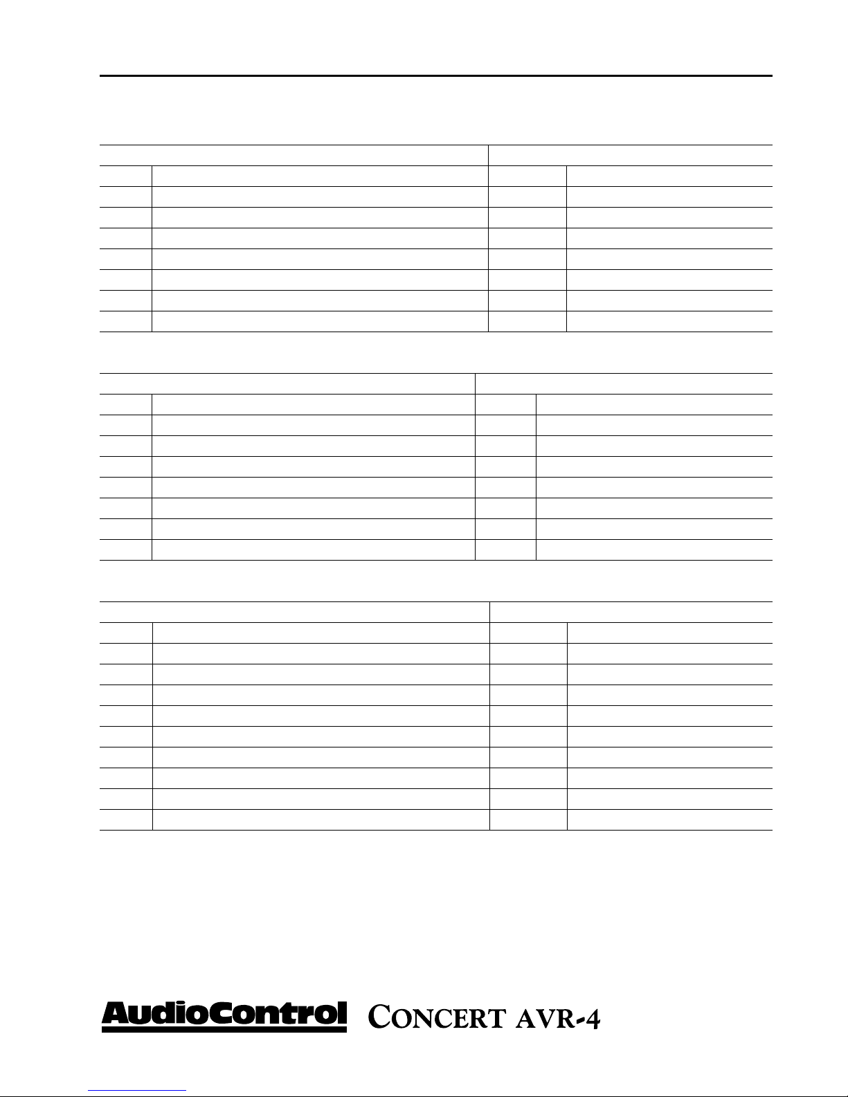
autoMatIon IntegratIon
FM Genre 0x03
Command Response
<ST> 0x21 <ST> 0x21
<ZN> Zone number <ZN> Zone number
<CC> 0x03 <CC> 0x03
<DL> 0x01 <AC> Answer code
<DATA> 0xF0 <DL> (v) variable
<ETR> 0x0D <DATA1> - Program type in ASCII characters
<DATA(v)
<ETR> 0x0D
Tuner preset - recall and status 0x15
Command Response
<ST> 0x21 <ST> 0x21
<ZN> Zone number <ZN> Zone number
<CC> 0x15 <CC> 0x15
<DL> 0x01 <AC> Answer code
<DATA> 0xF0 - current tuner preset <DL> 0x01
0x01 - 0x32 (1-50) - preset <DATA> 0xFF - Currently no preset selected
number to be recalled 0x01 - 0x32 (1-50) - current preset number
<ETR> 0x0D <ETR> 0x0D
Tune 0x16
Command Response
<ST> 0x21 <ST> 0x21
<ZN> Zone number <ZN> Zone number
<CC> 0x16 <CC> 0x16
<DL> 0x01 <AC> Answer code
<DATA> 0x01 - Increment frequency by 1 <DL> 0x02
0x00 - Decrement frequency by 1 <DATA1> FM: Frequency - MHz
0xF0 - Current frequency status AM: Frequency - 1000’s & 100’s - kHz
<ETR> 0x0D <DATA2> FM: Frequency - 10’s kHz
AM: Frequency - 10’s & 1’s kHz
<ETR> 0x0D
Phone 425-775-8461 • www.audiocontrol.com
®
45

autoMatIon IntegratIon
Request Sirius station 0x18
Command Response
<ST> 0x21 <ST> 0x21
<ZN> Zone number <ZN> Zone number
<CC> 0x18 <CC> 0x18
<DL> 0x01 <AC> Answer code
<DATA> 0xF0 <DL> (v) variable
<ETR> 0x0D <DATA> Program label of Sirius station in ASCII characters
<ETR> 0x0D
Request Sirius station program type 0x19
Command Response
<ST> 0x21 <ST> 0x21
<ZN> Zone number <ZN> Zone number
<CC> 0x19 <CC> 0x19
<DL> 0x01 <AC> Answer code
<DATA> 0xF0 <DL> (v) variable
<ETR> 0x0D <DATA> Program type of Sirius station in ASCII characters
<ETR> 0x0D
Request DLS information from current station 0x1A
Command Response
<ST> 0x21 <ST> 0x21
<ZN> Zone number <ZN> Zone number
<CC> 0x1A <CC> 0x1A
<DL> 0x01 <AC> Answer code
<DATA> 0xF0 - Sirius DLS request <DL> (v) variable
<ETR> 0x0D <DATA> Label of Sirius program in ASCII characters
<ETR> 0x0D
46
®
Phone 425-775-8461 • www.audiocontrol.com

autoMatIon IntegratIon
Request preset details 0x1B
Command Response
<ST> 0x21 <ST> 0x21
<ZN> Zone number <ZN> Zone number
<CC> 0x1B <CC> 0x1B
<DL> 0x01 <AC> Answer code
<DATA> 0x01-0x32 (1-50): number of the preset <DL> (v) variable
<ETR> 0x0D <DATA1> 0x01-0x32 (1-50): number of the preset
<DATA2> 0x00 - AM frequency
0x01 - FM frequency
0x04 - Sirius
<DATA3> FM: Frequency - MHz
AM: Frequency - 1000’s & 100’s - kHz
<DATA4> FM: Frequency - 10’s kHz
AM: Frequency - 10’s & 1’s kHz
<DATA(v)> The Sirius name in ASCII characters
<ETR> 0x0D
Network playback status 0x1C
Command Response
<ST> 0x21 <ST> 0x21
<ZN> Zone number <ZN> Zone number
<CC> 0x1C <CC> 0x1C
<DL> 0x01 <AC> Answer code
<DATA> 0xF0 <DL> (v) variable
<ETR> 0x0D <DATA1> 0x00 - Navigating
0x01 - Playing
0x02 - Paused
0xFF - Busy/Not Playing
<DATA2> - Name of folder if navigating - ASCII characters
<DATA(v)> Name of file if playing or paused - ASCII characters
<ETR> 0x0D
Restore factory default settings 0x05
Command Response
<ST> 0x21 <ST> 0x21
<ZN> 0x01 <ZN> 0x01
<CC> 0x05 <CC> 0x05
<DL> 0x01 <AC> Answer code
<DATA1> 0xAA <DL> 0x00
<DATA2> 0xAA <ETR> 0x0D
<ETR> 0x0D
Phone 425-775-8461 • www.audiocontrol.com
®
47

autoMatIon IntegratIon
Display information type 0x09
Command Response
<ST> 0x21 <ST> 0x21
<ZN> 0x01 <ZN> 0x01
<CC> 0x09 <CC> 0x05
<DL> 0x01 <AC> Answer code
<DATA> For all sources: <DL> 0x01
0x00 - Set the display to Processing mode <DATA> Current display is returned - per command
0xD0 - Set the display to Time and Date <ETR> 0x0D
0xE0 - Cycle through all displayable information
0xF0 Current diplay type
If current source is set to NET:
0x01 - Set the display to Track
0x02 - Set display to Artist
0x03 - Set display to Album
0x04 - Set display to audio type
0x05 - Set display to rate
If current source is Sirius
0x01 - Set display to Artist
0x02 - Set display to Composer
0x03 - Set display to Category Name
0x04 - Set display to Signal Strength
If current source is FM
0x01 - Set display to Radio text
0x02 - Set display to Program type
0x03 - Set display to Signal strength
If current source is AM
0x01 - Set display to Signal strength
<ETR> 0x0D
Headphone over-ride 0x1F
Activates Zone 1 mute relays when headphones are connected
Command Response
<ST> 0x21 <ST> 0x21
<ZN> 0x01 <ZN> 0x01
<CC> 0x1F <CC> 0x05
<DL> 0x01 <AC> Answer code
<DATA> 0x01 - Activate mute relay <DL> 0x00
0x00 - Deactivate mute relays <DATA> State of mute relay
<ETR> 0x0D <ETR> 0x0D
48
®
Phone 425-775-8461 • www.audiocontrol.com

autoMatIon IntegratIon
Request incoming audio format 0x43
Command Response
<ST> 0x21 <ST> 0x21
<ZN> Zone number <ZN> Zone number
<CC> 0x43 <CC> 0x43
<DL> 0x01 <AC> Answer code
<DATA> 0xF0 <DL> 0x02
<ETR> 0x0D <DATA 1> Format of incoming audio stream
0x00 PCM
0x01 Analog Direct
0x02 Dolby Digital
0x03 Dolby Digital EX
0x04 Dolby Digital Surround
0x05 Dolby Digital Plus
0x06 Dolby Digital True HD
0x07 DTS
0x08 DTS 96/24
0x09 DTS ES Matrix
0x0A DTS ES Discrete
0x0B DTS ES Matrix 96/24
0x0C DTS ES Discrete 96/24
0x0D DTS HD Master Audio
0x0E DTS HD High Res Audio
0x0F DTS Low Bit Rate
0x10 DTS Core
0x11 AAC
0x12 MPEG
0x13 Unsupported
0x14 Undetected
Phone 425-775-8461 • www.audiocontrol.com
®
49

autoMatIon IntegratIon
Request incoming audio format 0x43 (continued)
Command Response
<DATA 2> Configuration of the incoming audio channels
0x00 Dual Mono
0x01 Center only
0x02 Stereo only
0x03 Stereo + mono surround
0x04 Stereo + Surround L&R
0x05 Stereo + Surround L&R +mono surround back
0x06 Stereo + Surround L&R + surround back L&R
0x07 Stereo + Surround L&R containing matrix information for surround L&R
0x08 Stereo + Center
0x09 Stereo + Center + mono surround
0x0A Stereo + Center + Surround L&R
0x0B Stereo + Center + Surround L&R + mono surround back
0x0C Stereo + Center + Surround L&R +surround back L&R
0x0D Stereo + Center + Surround L&R containing matrix information for surround back L&R
0x0E Stereo Downmix (Left total Right total)
0x0F Stereo Only (Left Only Right Only)
0x10 Dual Mono + LFE
0x11 Center + LFE
0x12 Stereo + LFE
0x13 Stereo + single surround +LFE
0x14 Stereo + Surround L&R + LFE
0x15 Stereo + Surround L&R + mono Surround Back + LFE
0x16 Stereo + Surround L&R + surround back L&R +LFE
0x17 Stereo + Surround L&R + LFE
0x18 Stereo + Center + LFE containing matrix information for surround back L&R
0x19 Stereo + Center + single surround + LFE
0x1A Stereo + Surround L&R + LFE Standard 5.1
0x1B Stereo + Center + Surround L&R + mono Surround back +LFE 6.1
0x1C Stereo + Center + Surround L&R + Surround Back L&R + LFE
0x1D Stereo + Center + Surround L&R +
0x1E Stereo Downmix (Lt & Rt) + LFE
0x1F Stereo Only (Lo&Ro) + LFE
0x20 Unknown
0x21 Undetected
<ETR> 0x0D
LFE, containing matrix information for surround back L&R 6.1
50
®
Phone 425-775-8461 • www.audiocontrol.com

autoMatIon IntegratIon
Treble EQ 0x35
Command Response
<ST> 0x21 <ST> 0x21
<ZN> Zone Number <ZN> Zone number
<CC> 0x35 <CC> 0x35
<DL> 0x01 <AC> Answer code
<DATA> 0x00 - 0x0A - Set treble to 0db - +10db <DL> 0x01
0x81 - 0x8A - Set treble to –1db - –10db <DATA> 0x00 - 0x0A - Treble is set to 0db - 10db
0xF1 - increment 1db 0x81 - 0x8A - Treble is set to –1db - –10db
0xF2 - decrement 1db <ETR> 0x0D
0xF0 - Request current treble value
<ETR> 0x0D
Bass EQ 0x36
Command Response
<ST> 0x21 <ST> 0x21
<ZN> Zone Number <ZN> Zone number
<CC> 0x36 <CC> 0x36
<DL> 0x01 <AC> Answer code
<DATA> 0x00 - 0x0A - Set bass to 0db - +10db <DL> 0x01
0x81 - 0x8A - Set bass to –1db - –10db <DATA> 0x00 - 0x0A - Bass is set to 0db - 10db
0xF1 - increment 1db 0x81 - 0x8A - Bass is set to –1db - –10db
0xF2 - decrement 1db <ETR> 0x0D
0xF0 - Request current treble value
<ETR> 0x0D
Room EQ 0x37
Command Response
<ST> 0x21 <ST> 0x21
<ZN> Zone Number <ZN> Zone number
<CC> 0x37 <CC> 0x37
<DL> 0x01 <AC> Answer code
<DATA> 0xF0 - Request current Room EQ status <DL> 0x01
0xF1 - Room EQ on <DATA> 0x00 - Room EQ is off
0xF2 - Room EQ off 0x01 - Room EQ on
<ETR> 0x0D 0x02 - Room EQ has not been calculated
<ETR> 0x0D
Phone 425-775-8461 • www.audiocontrol.com
®
51
autoMatIon IntegratIon
Dolby Volume 0x38
Command Response
<ST> 0x21 <ST> 0x21
<ZN> Zone Number <ZN> Zone number
<CC> 0x38 <CC> 0x38
<DL> 0x01 <AC> Answer code
<DATA> 0x00 - Dobly Volume is off <DL> 0x01
0x01 - Dolby Volume is on in Music mode <DATA> 0x00 - Dolby Volume is off
0x02 - Dolby Volume is on in Movie mode 0x01 - Dolby Volume is on in Music mode
0xF0 - Request current Dolby Volume mode 0x02 - Dolby Volume is on in Movie mode
<ETR> 0x0D <ETR> 0x0D
Dolby Leveller 0x39
Command Response
<ST> 0x21 <ST> 0x21
<ZN> Zone Number <ZN> Zone number
<CC> 0x38 <CC> 0x39
<DL> 0x01 <AC> Answer code
<DATA> 0x00 - 0x0A - Set Dolby Leveller to 0 - 10 <DL> 0x01
0xF0 - Request current Dolby Leveller setting 10 <DATA> 0x00 - 0x0A - Dolby Leveller setting is 0 - 10
0xF1 - Increment Dolby Leveller setting 0xFF - Dolby Leveller is off
0xF2 - Decrement Dolby Leveller setting <ETR> 0x0D
0xFF - Turn off Dolby Leveller
<ETR> 0x0D
Dolby Volume Calibration 0x3A
Command Response
<ST> 0x21 <ST> 0x21
<ZN> Zone Number <ZN> Zone number
<CC> 0x3A <CC> 0x3A
<DL> 0x01 <AC> Answer code
<DATA> 0x00 - 0x0F - Set the calibration offset to 0 - 15db <DL> 0x01
0x80 - 0x8F - Set the calibration offset to –1 - –15db <DATA> 0x00 - 0x0F - Calibration offset is 0 - 15db
0xF0 - Request current calibration offset 0x80 - 0x8F - Calibration offset is –1 - –15db
0xF1 - increment calibration offset by 1db <ETR> 0x0D
0xF2 - Decrement calibration offset by 1db
<ETR> 0x0D
52
®
Phone 425-775-8461 • www.audiocontrol.com

autoMatIon IntegratIon
Balance 0x3B
Command Response
<ST> 0x21 <ST> 0x21
<ZN> Zone Number <ZN> Zone number
<CC> 0x3B <CC> 0x3B
<DL> 0x01 <AC> Answer code
<DATA> 0x00 - 0x06 - Set the balance to 0 - 6 <DL> 0x01
0x81 - 0x86 - Set the balance to –1 - –6 <DATA> 0x00 - 0x06 - Balance is 0 - 6
0xF0 - Request current balance 0x81 - 0x86 - Balance is –1 - –6
0xF1 - Increment the balance by 1db <ETR> 0x0D
0xF2 - Decrement the balance by 1db
<ETR> 0x0D
Dolby Pro Logic II Dimension 0x3C
Command Response
<ST> 0x21 <ST> 0x21
<ZN> Zone Number <ZN> Zone number
<CC> 0x3C <CC> 0x3C
<DL> 0x01 <AC> Answer code
<DATA> 0x00 - 0x03 - Set Pro Logic II Dimension parameter to 0 - 3 <DL> 0x01
0x81 - 0x83 - Set Pro Logic II Dimension parameter to –1 - –3 <DATA> 0x00 - 0x03 Pro Logic II Dimension is 0 - 3
0xF0 - Request current Pro Logic II Dimension setting 0x81 - 0x83 Pro Logic II Dimension is –1 - –3
0xF1 - Increment the Pro Logic II Dimension <ETR> 0x0D
0xF2 - Decrement the Pro Logic II Dimension
<ETR> 0x0D
Dolby Pro Logic II Center Width 0x3D
Command Response
<ST> 0x21 <ST> 0x21
<ZN> Zone Number <ZN> Zone number
<CC> 0x3D <CC> 0x3D
<DL> 0x01 <AC> Answer code
<DATA> 0x00 - 0x07 - Set Pro Logic II Center Width parameter to 0 - 7 <DL> 0x01
0xF0 - Request current Pro Logic II Center Width setting <DATA> 0x00 - 0x07 - Pro Logic II Center Width
parameter is 0 - 7
0xF1 - increment the Pro Logic II Center Width setting <ETR> 0x0D
0xF2 - Decrement the Pro Logic II Center Width setting
<ETR> 0x0D
Phone 425-775-8461 • www.audiocontrol.com
®
53
autoMatIon IntegratIon
Dolby Pro Logic II Panorama 0x3E
Command Response
<ST> 0x21 <ST> 0x21
<ZN> Zone Number <ZN> Zone number
<CC> 0x3E <CC> 0x3E
<DL> 0x01 <AC> Answer code
<DATA> 0xF0 - Request current Pro Logic II Panorama setting <DL> 0x01
0xF1 - Set Dolby Pro Logic II Panorama on <DATA> 0x00 - Dolby Pro Logic II Panorama is off
0xF2 - Set Dolby Pro Logic II Panorama off 0x01 - Dolby Pro Logic II Panorama is on
<ETR> 0x0D <ETR> 0x0D
Subwoofer Trim 0x3F
Command Response
<ST> 0x21 <ST> 0x21
<ZN> Zone Number <ZN> Zone number
<CC> 0x3F <CC> 0x3F
<DL> 0x01 <AC> Answer code
<DATA> 0x00 - 0x28 - Set positive subwoofer trim in <DL> 0x01
0.25db steps (e.g. 0x08 = +2db)
0x81 - 0A8 - Set negative subwoofer trim <DATA> 0x00 - 0x28 - Positive subwoofer trim in
in 0.25db steps (e.g. 0x89 = -2.25db) 0.25db
0xF0 - Request current subwoofer trim value 0x81 - 0xA8 - Negative subwoofer trim in
0.25db
0xF1 - Increment the subwoofer trim by 1db <ETR> 0x0D
0xF2 - Decrement the subwoofer trim by 1db
<ETR> 0x0D
Lipsync Delay 0x40
Command Response
<ST> 0x21 <ST> 0x21
<ZN> Zone Number <ZN> Zone number
<CC> 0x40 <CC> 0x40
<DL> 0x01 <AC> Answer code
<DATA> 0x00 - 0xC8 - set lipsync delay in 5ms steps (e.g. 0x06 = 30ms) <DL> 0x01
0xF0 Request current lipsync delay setting <DATA> 0x00 - 0xC8 - lipsync delay in 5ms steps
0xF1 Increment lipsync delay setting by 5ms <ETR> 0x0D
0xF2 Decrement lipsync delay setting by 5ms
<ETR> 0x0D
54
®
Phone 425-775-8461 • www.audiocontrol.com

autoMatIon IntegratIon
Compression 0x41
Command Response
<ST> 0x21 <ST> 0x21
<ZN> Zone Number <ZN> Zone number
<CC> 0x41 <CC> 0x41
<DL> 0x01 <AC> Answer code
<DATA> 0x00 - Compression off <DL> 0x01
0x01 - Set compression to On/Auto (follows HD audio <DATA> 0x00 - Compression off
stream metadata compression flag and sets compression
to On if no metadata is present )
0x02 - set compression to On 0x01 - Compression is set to On/Auto
0xF0 - Request current compression setting 0x02 - Compression is On
<ETR> 0x0D <ETR> 0x0D
Request incoming video parameters 0x42
Command Response
<ST> 0x21 <ST> 0x21
<ZN> Zone Number <ZN> Zone number
<CC> 0x42 <CC> 0x42
<DL> 0x01 <AC> Answer code
<DATA> 0xF0 - Request incoming video parameters <DL> 0x07
<ETR> 0x0D <DATA1>
<DATA2>
<DATA3>
<DATA4>
<DATA5> Refresh rate for full image update (half the field rate for
interlaced signals) (e.g. for 60Hz interlaced: 0x1E)
<DATA6> 0x00 - progressive
0x01 - interlaced
<DATA7> Aspect:
0x00 - undefined
0x01 - 4:3
0x02 - 16:9
<ETR> 0x0D
Horizontal resolution MSB (e.g. for 1080p: 0x07 since 1920 =0x0780)
Horizontal resolution LSB (e.g. for 1080p: 0x80 since 1920 = 0x0780)
Vertical resolution MSB (e.g. for 1080p: 0x04 since 1080 = 0x0438)
Vertical resolution LSB (e.g. for 1080p: 0x38 since 1080 = 0x0438)
Phone 425-775-8461 • www.audiocontrol.com
®
55

autoMatIon IntegratIon
Request incoming audio sample rate 0x44
Command Response
<ST> 0x21 <ST> 0x21
<ZN> Zone Number <ZN> Zone number
<CC> 0x44 <CC> 0x44
<DL> 0x01 <AC> Answer code
<DATA> 0xF0 - Request incoming audio sample rate <DL> 0x01
<ETR> 0x0D <DATA> 0x00 - 32KHz
0x01 - 44.1KHz
0x02 - 48KHz
0x03 - 88.2KHz
0x04 - 96KHz
0x05 - 176.4KHz
0x06 - 196KHz
0x07 - unknown
0x08 - undetected
<ETR> 0x0D
Set/request Sub Stereo Trim 0x45
Query or set the sub trim value for stereo mode
Command Response
<ST> 0x21 <ST> 0x21
<ZN> Zone Number <ZN> Zone number
<CC> 0x45 <CC> 0x45
<DL> 0x01 <AC> Answer code
<DATA> 0x00 - set the Sub Stereo Trim to 0db <DL> 0x01
0x80 - 0xA8 - set the Sub Stereo Trim value to -0.25db – -10.00db <DATA> 0x00 0xF0 - Request Sub Stereo Trim value 0x80 - 0xA8 - Sub Stereo Trim value in
-0.25db steps
0xF1 - Increment Sub Stereo Trim value by 0.25db steps <ETR> 0x0D
0xF2 - Decrement Sub Stereo Trim value by 0.25db steps
<ETR> 0x0D
Sub Stereo Trim value is set to 0.00db
56
®
Phone 425-775-8461 • www.audiocontrol.com

autoMatIon IntegratIon
Set/Request Video Brightness 0x46
Command Response
<ST> 0x21 <ST> 0x21
<ZN> Zone Number <ZN> Zone number
<CC> 0x46 <CC> 0x46
<DL> 0x01 <AC> Answer code
<DATA> 0x00 - 0x0A - set the Brightness value to 0 - 10 <DL> 0x01
0x81 - 0x8A - set the Brightness value to –1 - –10 <DATA> 0x00 - 0x0A - Brightness value 0 - 10
0xF0 - Request Brightness value 0x81 - 0x8A - Brightness value –1 - –10
0xF1 - Increment Brightness value by 1 <ETR> 0x0D
0xF2 - Decrement Brightness value by 1
<ETR> 0x0D
Set/Request Contrast 0x47
Command Response
<ST> 0x21 <ST> 0x21
<ZN> Zone Number <ZN> Zone number
<CC> 0x47 <CC> 0x47
<DL> 0x01 <AC> Answer code
<DATA> 0x00 - 0x0A - set the Contrast value to 0 - 10 <DL> 0x01
0x81 - 0x8A - set the Contrast value to –1 - –10 <DATA> 0x00 - 0x0A - Contrast value 0 - 10
0xF0 - Request Contrast value 0x81 - 0x8A -
0xF2 - Decrement Contrast value by 1
<ETR> 0x0D
0xF1 - Increment Contrast value by 1 <ETR> 0x0D
Contrast value -1 – -10
Set/Request Color 0x48
Command Response
<ST> 0x21 <ST> 0x21
<ZN> Zone Number <ZN> Zone number
<CC> 0x48 <CC> 0x48
<DL> 0x01 <AC> Answer code
<DATA> 0x00 - 0x0A - set the Color value to 0 - 10 <DL> 0x01
0x81 - 0x8A - set the Color value to –1 - –10 <DATA> 0x00 - 0x0A - Color value 0 - 10
0xF0 - Request Color value 0x81 - 0x8A - Color value –1 - –10
0xF1 - Increment Color value by 1 <ETR> 0x0D
0xF2 - Decrement Color value by 1
<ETR> 0x0D
Phone 425-775-8461 • www.audiocontrol.com
®
57

autoMatIon IntegratIon
Set/Request Picture Mode 0x49
Command Response
<ST> 0x21 <ST> 0x21
<ZN> Zone Number <ZN> Zone number
<CC> 0X49 <CC> 0x49
<DL> 0X01 <AC> Answer code
<DATA> 0X00 - Set Picture Mode to Auto <DL> 0x01
0x01 - Set Picture Mode to Video <DATA> 0x00 - Picture Mode is set to Auto
0x02 - Set Picture mode to Film 0x01 - Picture Mode is set to Video
0xF0 - Request Picture Mode 0x02 - Picture Mode is set to Film
0xF1 - Increment Picture Mode <ETR> 0x0D
0xF2 - Decrement Picture Mode
<ETR> 0x0D
Set/Request Edge Enhancment 0x4A
Command Response
<ST> 0x21 <ST> 0x21
<ZN> Zone Number <ZN> Zone number
<CC> 0x4A <CC> 0x4A
<DL> 0x01 <AC> Answer code
<DATA> 0x00 - Set Edge Enhancement to Off <DL> 0x01
0x01 - Set Edge Enhancement to Low <DATA> 0x00 - Edge Enhancement is Off
0x02 - Set Edge Enhancement to Medium 0x01 - Edge Enhancement is set to Low
0x03 - Set Edge Enhancement to High 0x02 - Edge Enhancement is set to Medium
0xF0 - Request current Edge Enhancement value 0x03 - Edge Enhancement is set to High
0xF1 - Increment Edge Enhancement value <ETR> 0x0D
0xF2 - Decrement Edge Enhenacement value
<ETR> 0x0D
58
®
Phone 425-775-8461 • www.audiocontrol.com

autoMatIon IntegratIon
Set/Request Mosquito Noise Reduction 0x4B
Command Response
<ST> 0x21 <ST> 0x21
<ZN> Zone Number <ZN> Zone number
<CC> 0x4B <CC> 0x4B
<DL> 0x01 <AC> Answer code
<DATA> 0x00 - Set Mosquito NR to Off <DL> 0x01
0x01 - Set Mosquito NR to Low <DATA> 0x00 - Mosquito NR is Off
0x02 - Set Mosquito NR to Medium 0x01 - Mosquito NR is set to Low
0x03 - Set Mosquito NR to High 0x02 - Mosquito NR is set to Medium
0xF0 - Request current Mosquito NR value 0x03 - Mosquito NR is set to High
0xF1 - Increment Mosquito NR value <ETR> 0x0D
0xF2 - Decrement Mosquito NR value
<ETR> 0x0D
Set/Request Noise Reduction 0x4C
Command Response
<ST> 0x21 <ST> 0x21
<ZN> Zone Number <ZN> Zone number
<CC> 0x4C <CC> 0x4C
<DL> 0x01 <AC> Answer code
<DATA> 0x00 - Set Noise Reduction to Off <DL> 0x01
0x01 - Set Noise Reduction to Low <DATA> 0x00 - Noise Reduction is Off
0x02 - Set Noise Reduction to Medium 0x01 - Noise Reduction is set to Low
0x03 - Set Noise Reduction to High 0x02 - Noise Reduction is set to Medium
0xF0 - Request current Noise Reduction value 0x03 - Noise Reduction is set to High
0xF1 - Increment Noise Reduction value <ETR> 0x0D
0xF2 - Decrement Noise Reduction value
<ETR> 0x0D
Phone 425-775-8461 • www.audiocontrol.com
®
59
autoMatIon IntegratIon
Set/Request Block Noise Reduction 0x4D
Command Response
<ST> 0x21 <ST> 0x21
<ZN> Zone Number <ZN> Zone number
<CC> 0x4D <CC> 0x4D
<DL> 0x01 <AC> Answer code
<DATA> 0x00 - Set Block Noise Reduction to Off <DL> 0x01
0x01 - Set Block Noise Reduction to Low <DATA> 0x00 - Block Noise Reduction is Off
0x02 - Set Block Noise Reduction to Medium 0x01 - Block Noise Reduction is set to Low
0x03 - Set Block Noise Reduction to High 0x02 - Block Noise Reduction is set to Medium
0xF0 - Request current Block Noise Reduction value 0x03 - Block Noise Reduction is set to High
0xF1 - Increment Block Noise Reduction value <ETR> 0x0D
0xF2 - Decrement Block Noise Reduction value
<ETR> 0x0D
Set/Request Zone 1 OSD 0x4E
Command Response
<ST> 0x21 <ST> 0x21
<ZN> Zone Number <ZN> Zone number
<CC> 0x4E <CC> 0x4E
<DL> 0x01 <AC> Answer code
<DATA> 0xF0 - Request current state of Zone 1 OSD <DL> 0x01
0xF1 - Set Zone 1 OSD to On <DATA> 0x00 - Zone 1 OSD is On
0xF2 - Set Zone 1 OSD to Off 0x01 - Zone 1 OSD is Off
<ETR> 0x0D <ETR> 0x0D
60
®
Phone 425-775-8461 • www.audiocontrol.com

autoMatIon IntegratIon
Set/Request Video Output Switching 0x4F
Sets or Requests the HDMI video output selection and priority
Command Response
<ST> 0x21 <ST> 0x21
<ZN> Zone Number <ZN> Zone number
<CC> 0x4F <CC> 0x4F
<DL> 0x01 <AC> Answer code
<DATA> 0x00 - Set HDMI Output 1 Auto-Priority <DL> 0x01
0x01 - Set HDMI Output 2 Auto-Priority <DATA> 0x00 - HDMI Ouput 1 Auto-Priority
0x02 - Set HDMI Output 1 0x01 - HDMI Output 2 Auto-Priority
0x03 - Set HDMI Output 2 0x02 - HDMI Output 1
0x04 - Set HDMI Output 1 & 2 0x03 - HDMI Output 2
0xF0 - Request current video output switching 0x04 - HDMI Output 1 & 2
0xF1 - Increment setting <ETR> 0x0D
0xF2 - Decrement setting
<ETR> 0x0D
Set/Request Output Frame Rate 0x50
Command Response
<ST> 0x21 <ST> 0x21
<ZN> Zone Number <ZN> Zone number
<CC> 0x50 <CC> 0x50
<DL> 0x01 <AC> Answer code
<DATA> 0x00 - Set the Frame Rate to Auto <DL> 0x01
0x01 - Set the Frame Rate to Follow the Source <DATA> 0x00 - Frame Rate is set to Auto
0x02 - Set the Frame Rate to 50Hz 0x01 - Frame Rate is set to 50Hz
0x03 - Set the Frame Rate to 60Hz 0x02 - Frame Rate is set to 60Hz
0xF0 - Request the current Frame Rate <ETR> 0x0D
0xF1 - Increment setting
0xF2 - Decrement setting
<ETR> 0x0D
Phone 425-775-8461 • www.audiocontrol.com
®
61

autoMatIon IntegratIon
RC5 code table
General functions
System Code Command Code
Stand-by 16 - 12
Power on 16 - 123
Power off 16 - 124
Mute toggle 16 - 13
Mute on 16 - 119
Mute off 16 - 120
Volume up 16 - 16
Volume down 16 - 17
Menu 16 - 82
Display brightness 16 - 59
Select 16 - 87
Select SAT 16 - 0
Select Phono 16 - 1
Select DVD 16 - 4
Select AV 16 - 2
Select NET 16 - 11
Select DVR 16 - 34
Select Tuner 16 - 3
Select AM 16 - 52
Select FM 16 - 54
Select Sirius 16 - 72
Select Tape 16 - 5
Select VCR 16 - 6
Select CD 16 - 7
Select Aux 16 - 8
Select Multi-channel 16 - 9
Random 16 - 48
Repeat 16 - 49
Navigate up 16 - 86
Navigate down 16 - 85
Navigate right 16 - 80
Navigate left 16 - 81
System Code Command Code
Cycle between Decode modes 16 - 32
Track forward 16 - 56
Track back 16 - 57
NET Play/pause 16 - 70
Direct mode on/off toggle 16 - 10
Discrete Direct mode on 16 - 78
Discrete Direct mode off 16 - 79
Room EQ on/off toggle / NET “Now playing” screen
16 - 30
Dolby Volume on/off toggle / NET Play & pause
16 - 70
Bass control menu 16 - 39
Bass increment 16 - 44
Bass decrement 16 - 45
Speaker trim 16 - 37
Subwoofer control menu 16 - 51
Subwoofer increment 16 - 105
Subwoofer decrement 16 - 108
Treble control menu 16 - 14
Treble incremement 16 - 46
Treble decrement 16 - 98
Favorite up 16 - 41
Favorite down 16 - 42
Home 16 - 43
Zone toggle 16 - 95
Follow Zone 1 16 - 20
Cycle between output resolutions
16 - 47
Cycle between aspect ratios 16 - 19
Lipsync control menu 16 - 50
Lipsync increment by 1ms 16 - 100
Lipsync decrement by 1ms 16 - 101
62
®
Phone 425-775-8461 • www.audiocontrol.com

autoMatIon IntegratIon
Tuner Functions
Number 0 17 - 0
Number 1 17 - 1
Number 2 17 - 2
Number 3 17 - 3
Number 4 17 - 4
Number 5 17 - 5
Number 6 17 - 6
Number 7 17 - 7
Number 8 17 - 8
Number 9 17 - 9
Select FM 16 - 54
Select AM 16 - 52
Increment preset/ Navigate up
17 - 86
Decrement preset/ Navigate down
17 - 85
Increase tuning/Navigate right
17 - 77
Decrease tuning/Navigate left
17 - 78
Band 17 - 50
Menu 17 - 125
Preset up/Sirius category up 17 - 32
Preset down/Sirius category down
17 - 33
Page down - preset list 17 - 37
Page up - preset list 17 - 38
Delete selected preset 17 - 41
Discrete Zone 2 & 3 commands
Zone 2 Power On 23 - 123
Zone 2 Power Off 23 - 124
Zone 2 Volume Up 23 - 1
Zone 2 Volume Down 23 - 2
Zone 2 Mute toggle 23 - 3
Zone 2 Mute on 23 - 4
Zone 2 Mute off 23 - 5
Zone 2 SAT 23 - 8
Zone 2 DVD 23 - 7
Zone 2 AV 23 - 9
Zone 2 NET 23 - 19
Zone 2 FM 23 - 14
Zone 2 AM 23 - 15
Zone 2 DVR 23 - 12
Zone 2 AUX 23 - 13
Zone 2 Tape 23 - 10
Zone 2 VCR 23 - 11
Zone 2 CD 23 - 6
Zone 2 Sirius 23 - 16
Zone 3 Power on 23 - 121
Zone 3 Power off 23 - 122
Zone 3 Volume Up 23 - 20
Zone 3 Volume Down 23 - 21
Zone 3 Mute 23 - 22
Zone 3 Mute On 23 - 23
Zone 3 Mute Off 23 - 24
Phone 425-775-8461 • www.audiocontrol.com
®
63

troublesHootIng
Troubleshooting Common Problems
General
There are no lights on the Concert AVR-4
ü Pressing any button or the Standby button on the front panel should wake
the Concert AVR-4.
ü Verify that the power cord is plugged into a live AC outlet.
ü Verify that the rear panel Power switch on the Concert AVR-4 is “On”.
The main front panel display is blank
ü Press the Display button. This button controls the display brightness and
also allows you to turn the display off entirely.
The main zone changes while selecting sources from Zone 2
ü Change the Zone 1 Control option in the Zone 2 Configuration Menu to
Off.
Video
No video/picture
ü Verify your video display or projector is turned on and set to the correct
input for the Concert AVR-4. Press the Menu button on the Concert AVR-4 and
look for the Main Menu to show on the video display.
ü Verify the correct input on the video display is selected for the output of
the source (i.e. Component Video if the output of the DVD player is Component).
ü Verify the Video Input assignment configurations. Make certain that the
correct video input is assigned to the source you are playing.
ü If at any point you need to reset the video output resolution and frame rate
to the default setting, push and hold the “Select” button for 3 seconds.
ü If you are using a Blu-ray player with a 1080p/24 fps (frames per second)
format, you will want to confirm the output format of the player you are using matches with the input format of your display device. The Concert AVR-4
supports both 1080p/24 fps (frames per second) and the more commonly used
1080p/60 fps video formats. To properly utilize the 1080p/24 format you will
want to make sure that the source device (i.e. Blu-ray player) and the display
device (i.e. projector or TV) are both capable of supporting this format. In the
Video Output section of the Setup menus, set the Output Resolution of your
Concert AVR-4 to 1080p (not Preferred) and make sure that the Frame Rate is
set to Auto. Failure to do any of the above could result in no image.
64
®
Phone 425-775-8461 • www.audiocontrol.com

Audio
troublesHootIng
No Video on Zone 2
ü Verify the composite video input from source is connected.
There is no On-Screen Display (OSD)
ü Verify the OSD is turned on in the Concert AVR-4 configuration
settings.
ü Verify that the correct input is selected on the video display or projector.
The audio doesn’t match the video
ü The Video and Audio input can be selected independently in the
Main Menu. Verify they are set the same.
ü Verify the correct Video Input and Digital Audio input assignments
are configured for the Source input button.
The sound is poor or distorted
ü Verify the speaker settings configuration matches your speakers. If
a speaker is set to Large and it cannot reproduce full range bass, you will
hear distortion.
ü If the trouble is only on some channels: Verify the audio RCA cables
to the power amplifiers are working and seated properly.
ü If the trouble is in all channels: Verify the Input Trim setting in the
Advanced Configurations is not set too low.
Cannot select Dolby Digital or DTS decoding mode
ü The Concert AVR-4 can only decode formats encoded onto the
source. Normally these are marked on the packaging or liner notes of the
material.
ü Verify that the correct format is selected in the Start menu of the
DVD.
ü Verify that the digital input from the source is properly connected to
the Concert AVR-4.
ü Verify that the digital output of the source is enabled. Some DVD
players have a setup menu that can only be accessed if there is no disk in
the player.
Phone 425-775-8461 • www.audiocontrol.com
®
65

troublesHootIng
Hum on analog inputs
ü Verify that all the two channel analog audio cables are connected
properly.
ü If the hum only occurs on one source, try a different set of connecting cables.
ü If the hum occurs on a source with an external connection such as an
antenna or cable TV, try disconnecting that input. If the hum disappears,
put a ground isolator on that connection.
No audio on Zone 2 or 3
ü Zone 2 and Zone 3 are muted when units is first turned on.
No Zone 2 audio when playing a DTS encoded video
ü Most DVD players cannot output a stereo analog version of the
soundtrack while playing a DTS encoded disk. If you want to watch the
movie in the second zone, select the Dolby Digital soundtrack on the disk.
Unable to adjust the Bass and Treble controls
ü The Bass and Treble tone controls are defeated.
66
®
Phone 425-775-8461 • www.audiocontrol.com

warranty
WARRANTY
…and now a word from the legal department...
People are scared of warranties. Lots of fine print. Months of waiting
around. Well, fear no more. This warranty is designed to make you rave
about us to your friends. It’s a warranty that looks out for you and helps you
resist the temptation to have your friend, who’s “good with electronics”, try
to repair your AudioControl product. So go ahead, read this warranty, then
take a few days to enjoy your new Concert AVR-4 home theater system
before logging onto the our web site at www.audiocontrol.com and register
your purchases.
“Conditional” doesn’t mean anything ominous. The Federal Trade Commission tells all manufacturers to use the term to indicate that certain
conditions have to be met before they’ll honor the warranty. If you meet all
of these conditions, we will warrant all materials and workmanship on the
Concert AVR-4 for five (5) years from the date you bought it, and we will
fix or replace it, at our option, during that time. Here are the conditional
conditions:
1. You need to register your purchases of the Concert AVR-4 with us
by going to the AudioControl web site (www.audiocontrol.com), click
on the “Home Theater” tab and then go to the warranty registration
department and follow the directions.
2. You must keep your sales receipt for proof of purchase showing
when and from whom the unit was bought. We’re not the only ones
who require this, so it’s a good habit to get into with any major purchase.
3. The Concert AVR-4 must have originally been purchased from
an authorized AudioControl dealer. You do not have to be the original owner, but you do need a copy of the original sales receipt or
invoice.
4. You cannot let anybody who isn’t: (A) the AudioControl factory;
(B) somebody authorized in writing by AudioControl to service the
Concert AVR-4. If anyone other than (A) or (B) messes with the
Concert AVR-4, that voids your warranty.
5. The warranty is also void if the serial number is altered or removed, or if the Concert AVR-4 has been used improperly. Now that
sounds like a big loophole, but here is all we mean by it:
Phone 425-775-8461 • www.audiocontrol.com
®
67

warranty
Unwarranted abuse is: (A) physical damage (don’t use the Concert AVR4 to level your projection TV); (B) improper connections (120 volts into
the RCA jacks can fry the poor thing); (C) sadistic things. This is the best
product we know how to build, but if you strap it to the front bumper of
your Range Rover, something will break.
Assuming you conform to 1 through 5 (and it really isn’t all that hard to
do) we get the option of fixing your original unit or replacing it with a new
one.
LEGALESE SECTION
This is the only warranty given by AudioControl. This warranty gives you
specific legal rights that vary from state to state. Promises of how well the
Concert AVR-4 will perform are not implied by this warranty. Other than
what we have covered in this warranty, we have no obligation, express
or implied. Also, we will not be obligated for direct or indirect consequential damage to your system caused by hooking up or operating the
AudioControl Concert AVR-4.
Failure to complete the warranty registration process negates any service
claims.
68
®
Phone 425-775-8461 • www.audiocontrol.com

SHOULD YOU EVER NEED SERVICE…
Normally service will be handled by your AudioControl system professional
who installed the system. If you’re the take charge kind of person who
wants to do this yourself, contact AudioControl, either by phone 425/7758461 or email to sound.better@audiocontrol.com. We’ll verify if there is
anything wrong that you can fix yourself, or assist you in arranging to have
it sent back to our factory for repair. Please include the following items with
the returning unit:
1. A copy of your proof of purchase (that sales receipt we’ve been harping
about). No originals please. We cannot guarantee returning them to you.
2. A brief explanation of the trouble you are having with the Concert AVR-
4.
3. A return street address. (No P.O. Boxes, please)
4. A daytime phone number in case our technician has a question
about the problem you are having.
sHould you need servICe
You’re responsible for the freight charges to us, but we’ll pay the return
freight back. We match whatever shipping method you send it to us, so if
you return the unit overnight freight, we send it back overnight. We recommend UPS for any shipments.
Phone 425-775-8461 • www.audiocontrol.com
®
69

speCIfICatIons
Specications
Concert AVR-4 Home Theater Receiver Specications
Inputs
Analog Audio Inputs .....................................7 Stereo Pairs
Nominal Audio Input Sensitivity. . . . . . . . . . . . . . . . . . . . . . . . . . . . . . 500mV-4V
Input Impedance ............................................47 ohms
Signal-to-noise ................................................100dB
Multi-channel Analog Audio Input ......................... 1 (8 channels)
Digital Audio Inputs ...................................3 Coax, 4 Optical
Video Inputs . . . . . . . . . . . . . . . . . . . . . . . 5 Component, 5 Composite, 5 S-Video
HDMI Inputs .....................................................5
Outputs
Speaker Level Channels. . . . . . . . . . . . . . . . . . . . . . . . . . . . . . . . . . . . . . . . . Seven
Power Output. . . . . . . 120 Watts Per Channel, All Channels Driven into 8 ohms
Minimum Speaker Load. . . . . . . . . . . . . . . . . . . . . . . . . . . . . . . . . . . . . . . . 4 ohms
Total Harmonic Distortion. . . . . . . . . . . . . . . . . . . . . . . . . . . . . . . . less than 0.2%
Frequency Response .....................................20Hz to 20kHz
HDMI Outputs ........................................... 2 assignable
Main Audio Outputs ....................... 7 main channels, 3 subwoofers
Digital Audio Output. . . . . . . . . . . . . . . . . . . . . . . . . . . . . . . . . . 1 Coax, 1 Optical
Main Video Outputs. . . . . . . . . . . . . . . . . . 1 Component, 3 Composite, 3 S-Video
Second Zone Output ............... Stereo Audio plus Composite & S-Video
Third Zone Output ......................................Stereo Audio
Control Audio
12 Volt Trigger Outputs ......................Three - Main, Zone 2, Zone 3
RS-232 Serial Control ........................................1 - DB-9
IR Receiver Input. . . . . . . . . . . Three – Main, Zone 2, Zone 3 (3.5 mm Minijack)
IR Emitter Output ...............................One (3.5 mm Minijack)
General
Power Consumption (Standby) ..................................3 Watts
Dimensions. . . . . . . . . . . . . . . . . . . . . . . . . . . . . . . . . . . . . . . 17”W x 16.5”D x 7H
Weight ...................................................... 60 lbs
70
®
Phone 425-775-8461 • www.audiocontrol.com


For Those Who Consider Perfection Possible
22410 70th Avenue West
Seattle, WA 98043 USA
425-775-8461 • Fax 425-778-3166
www.AudioControl.com
P/N 913-113-0
®
®
 Loading...