

AudioControl Avalon G4 Installation Manual
4 CHANNEL HIGH POWER AMPLIFIER OF DESTINY
Installation Manual

2
Important Safety
Instructions
1. Read these instructions.
2. Keep these instructions.
3. Heed all warnings.
4. Follow all instructions.
5. Do not use this apparatus near water.
6. Clean only with a dry cloth.
7. Do not block any ventilation openings. Install in accordance with the manufacturer’s
instructions.
8. Do not install near any heat sources such
as radiators, heat registers, stoves, or
other apparatus (including ampliers) that
produce heat.
9. Protect the power cord from being walked
on or pinched particularly at plugs, convenience receptacles, and the point where
they exit from the apparatus.
10. Only use attachments/accessories speci-
ed by the manufacturer.
11. Unplug this apparatus during lightning
storms or when unused for long periods of
time.
12. Refer all servicing to qualied service
personnel. Servicing is required when
the apparatus has been damaged in any
way, such as power-supply cord or plug is
damaged, liquid has been spilled or objects
have fallen into the apparatus, the apparatus has been exposed to rain or moisture,
does not operate normally, or has been
dropped.
13. This apparatus shall not be exposed to
dripping or splashing, and no object lled
with liquids, such as vases or glasses, shall
be placed on the apparatus.
The lightning ash with arrowhead
symbol within an equilateral triangle
is intended to alert the user to the
presence of uninsulated “dangerous voltage”
within the product’s enclosure, that may be
of sucient magnitude to constitute a risk of
electric shock to persons.
The exclamation point within an
equilateral triangle is intended to alert
the user of the presence of import-
ant operating and maintenance (servicing)
instructions in the literature accompanying the
appliance.
Caution: to reduce the risk of electric shock,
do not remove the top cover. There are no
user-serviceable parts inside. Refer servicing to
qualied personnel.
This equipment has been tested and found
to comply with the limits for a Class B digital
device, pursuant to part 15 of the FCC Rules.
These limits are designed to provide reasonable
protection against harmful interference in a
residential installation.
This equipment generates, uses, and can radiate radio frequency energy and, if not installed
and used in accordance with the instructions,
may cause harmful interference to radio communications. However, there is no guarantee
that interference will not occur in a particular
installation.
If this equipment does cause harmful interference to radio or television reception, which can
be determined by turning the equipment o
and on, the user is encouraged to try to correct
the interference by one or more of the following measures:
• Reorient or relocate the receiving antenna.
• Increase the separation between the equipment and the receiver.
• Connect the equipment into an outlet on
a circuit dierent from that to which the
receiver is connected.
• Consult the dealer or an experienced radio/
TV technician for help.
CAUTION: Changes or modications to this
device not expressly approved by AudioControl
Inc. could void the user’s authority to operate
the equipment under FCC rules.
Recycling notice: If the time comes
and this apparatus has fullled its
destiny, do not throw it out into the
trash. It has to be carefully recycled
for the good of mankind, by a facility specially
equipped for the safe recycling of electronic
apparatii. Please contact your local or state
recycling leaders for assistance in locating a
suitable nearby recycling facility. Or, contact us
and we might be able to repair it for you.
Important Safety Instructions

3
Installation Manual
Table of Contents
Table of Contents
Important Safety Instructions ...... 2
Introduction ..................... 4
Features ........................ 5
Quick View ...................... 7
Getting Started .................. 8
Front Panel Features .............. 9
Rear Panel Features .............. 10
Speaker and Wiring Impedance ..... 13
Installation ...................... 14
Congurations ................... 15
Ventilation ...................... 9
Advanced Discussions ............. 20
Troubleshooting ................. 22
Specications ................... 23
Block Diagram ................... 24
Service ......................... 25
The Warranty .................... 27
Blackhawk Waltz ................. 28
©2019 AudioControl Inc All rights reserved.
Based on a dream sequence while under the inuence of tea.
4
Flowery Marketing Introduction
Greetings from the rainforests of
the Pacic Northwest, the home of
AudioControl. Since you are reading this
manual, it is safe to say you are in the
process of installing a high-performance
AudioControl Avalon G4 4 Channel
theater amplier that also performs
as a killer hi 2.1 or a dual mono block.
You have unprecedented exibility with
this ridiculously powerful and adaptable
amplier which no doubt caught your
rened eye. You are obviously a person
of ne discernment, have nice hair, and
people like the cut of your jib.
You will be pleased to note that this
amplier was designed and manufactured
at our AudioControl forest technodrome,
located in the U.S.A. For over 40 years,
our company has been designing and
manufacturing high performance
components that allow enthusiasts to
truly enjoy their audio systems. It should
provide you and your customers with
years of enjoyment and trouble-free
service. We truly feel that this amplier
will enhance the performance of any
system.
This manual was written to assist with the
installation of this new amplier. Whether
Introduction
you are a seasoned veteran, or this is the
rst amplier you have ever heard, we
encourage you to set aside some time to
review this not-so-weighty prose. While
reading a manual can be as exciting as
watching a slug race, we have included
lots of useful information, carefully
concealed within a minimum of technical
jargon. Not only will you learn how to get
the most from this AudioControl home
theater power amplier, you might get a
smile or two. Anything as capable as this
amplier deserves all the explanation it
can get.
We also encourage you to visit the
AudioControl web site, conveniently
located at www.audiocontrol.com. While
we have tried to anticipate any installation
issues in this manual, there are sometimes
new applications and ideas that come to
mind. Therefore our web site will always
have the most current information.
Needless to say, if you have any real
challenging questions, feel free to call us
or e-mail us at:
sound.great@audiocontrol.com
Your Friends At AudioControl

5
Installation Manual
Features
Features
Here are some of the features that make
the Avalon G4 very unique, and unlike any
other amplier:
• CongurationFlexibility
With the Avalon G4, you have all the
prodigious power one could need
in an Atmos 4 channel amplier,
with all the exibility that comes
from AudioControl. With precision
Linkwitz-Riley crossovers and mono/
summed stereo pair operations,
you can set this bad boy up as a
2.1 amplier to run your highs
and a passive subwoofer (where
bridged, you can achieve 600 watts).
Even better for those who have a
hankering for power, set it up as a
dual monoblock which is a pair of 600
watt outputs! Nothing better!
• Built For The Long Haul
“Bulletproof” is the phrase that best
describes the Avalon G4. Everything
about this amplier is built for the
long haul, built for life! This amplier
has been designed with durability in
mind. The cool running Class H design
minimizes component-damaging
heat, while the Lightdrive system
protects your speakers from harmful
harmonics caused by clipping.
• Class H Design
Most ampliers have one speed, all
on. That means that during most of
music, up to 90% of the amp’s power
is just going up in heat. The Avalon
G4’s The Class H design takes care of
this problem by automatically and
intelligently adjusting the power
supply to t the power demands of
the moment.
• Lightdrive Protection System
The Lightdrive protection circuitry
defends this amplier like a momma
bear to her cubs - and defends
speakers against clipping, distortion,
damage, and annoying teenage
beach party movies, even if the
movie festival lasts all weekend. Each
channel is independently protected,
so a problem in one channel will not
aect the rest of the system.
• HighDenitionBiMOSOutput
Design
Home Theater audio systems place
terric demands on power ampliers.
The high current drive capabilities of
our BiMOS outputs cleanly delivers a
minimum of 230 watts into 4 ohms,
while maintaining a cool performance
method that smells great too!
• Unparalleledenergyeciency
Whether from the point of view
of saving electricity or from the
viewpoint of less heat in the rack,
this amplier has no equal. It is VERY
energy ecient during operation.
• MadeintheNorthwestRainforest
The AudioControl Avalon G4s began
their existence at our factory in
Mountlake Terrace, Washington, a
few miles north of Seattle. Here, we
also build precision test instruments,
equalizers and analyzers and a totally
awesome line of car stereo components. AudioControl started in 1977
and has won so many audio industry
awards for design and engineering
excellence that our reception room
wall is starting to sag.

6
Complimentary Features
Features continued
• Class H power - dynamically provides
incredible power
• Independent 24dB Linkwitz-Riley
High Pass and Low Pass crossovers
• Individual channel input gain
• Mono/stereo operation
• Balanced XLR and unbalanced RCA
inputs
• Analog RCA loop-through outputs
• Stout and sturdy 5-way binding posts
• Back panel channel LED status indicators
• Lightdrive signal management
• Prodigious power
• Ground isolation switch
• Front panel light bar brilliance setting
• Intuitive back panel for ease of set up
and control
• Heavy - use for weight lifting when
not listening

7
Installation Manual
Quick View
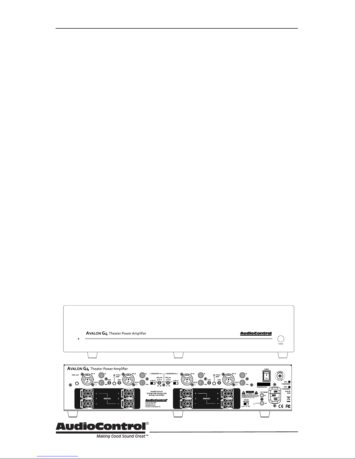
Quick View
Front Panel
8. Speaker outputs
9. Ground isolation switch
10.Mastertrigger
11. AC power switch
12. AC input
13. AC fuse
Rear Panel
1. Light bar brilliance setting
2. Inputs balanced and unbalanced
3. RCA Thru outputs
4. Level control
5. Stereo/Monoswitch
6. LP/OFF/HPswitch
7. FREQ (Hz) control
1. Power LED
2. Light Bar
3. Power Button
4. RackMountEars(optional)
12 43
8
9 10
123 4 5 67 11 12 13

8
Getting Started
1. Turn o power to all com-
ponents before making any
connections.
2. When making connections, des-
ignate red RCA plugs as right, and
designate white, black, or gray plugs
as left. This is a good idea for all signal connections made in your audio
system. The key is consistency. Stick
with the same color coding and you’ll
reduce possible problems.
3. Whenever possible, keep power
cords away from signal cables to prevent induced hum. This is especially
important if you bundle the cables to
keep the installation neat looking.
4. Use quality interconnect cables. We
know from experience that really
cheap cables can cause a multitude
of problems. They tend to break
inside or corrode, causing a loss of
signal or hum. They also have poor
shielding.
5. The Avalon G4 gives you the option
of using RCA cables or balanced XLR
cables – if running more than 20 feet
or so, it is best to run those signal cables as XLR to give you better noise
rejection.
If you do need to run the RCA audio
cables more than 20 feet, consider
using an active balanced line driver
for the signals. This will provide
better noise rejection against nasty
things like hum, spikes, local talk
radio, and metaphysical paranormal
phenomena, etc. The AudioControl
balanced line driver components
(BLD-10, BLR-10 and BLX-10) are an
excellent way to send audio over long
distances with standard Cat-5 wiring.
Check them out at audiocontrol.com.
Getting Started
6. Speaker Wiring – Establish a standard connection color code and stick
with it. One conductor of the speaker
wire is normally marked by a dierent color (silver versus copper) or
there is a ribbing on one side. Typically this marked conductor is used for
the positive (+) speaker leads. Some
wires have positive and negative
printed right onto the wire jacket.
Match the polarity markings on the
Avalon G4 unit with the polarity
markings on your speakers. If the wiring is incorrect then the speakers will
be out-of-phase, with a noticeable
decrease in the bass response and
less than goodly-sounding awesomeness.
7. For optimal performance, dance in a
fairy circle around your new amplier
at midnight, on the rst full moon of
the new year.
9
Installation Manual
Front Panel
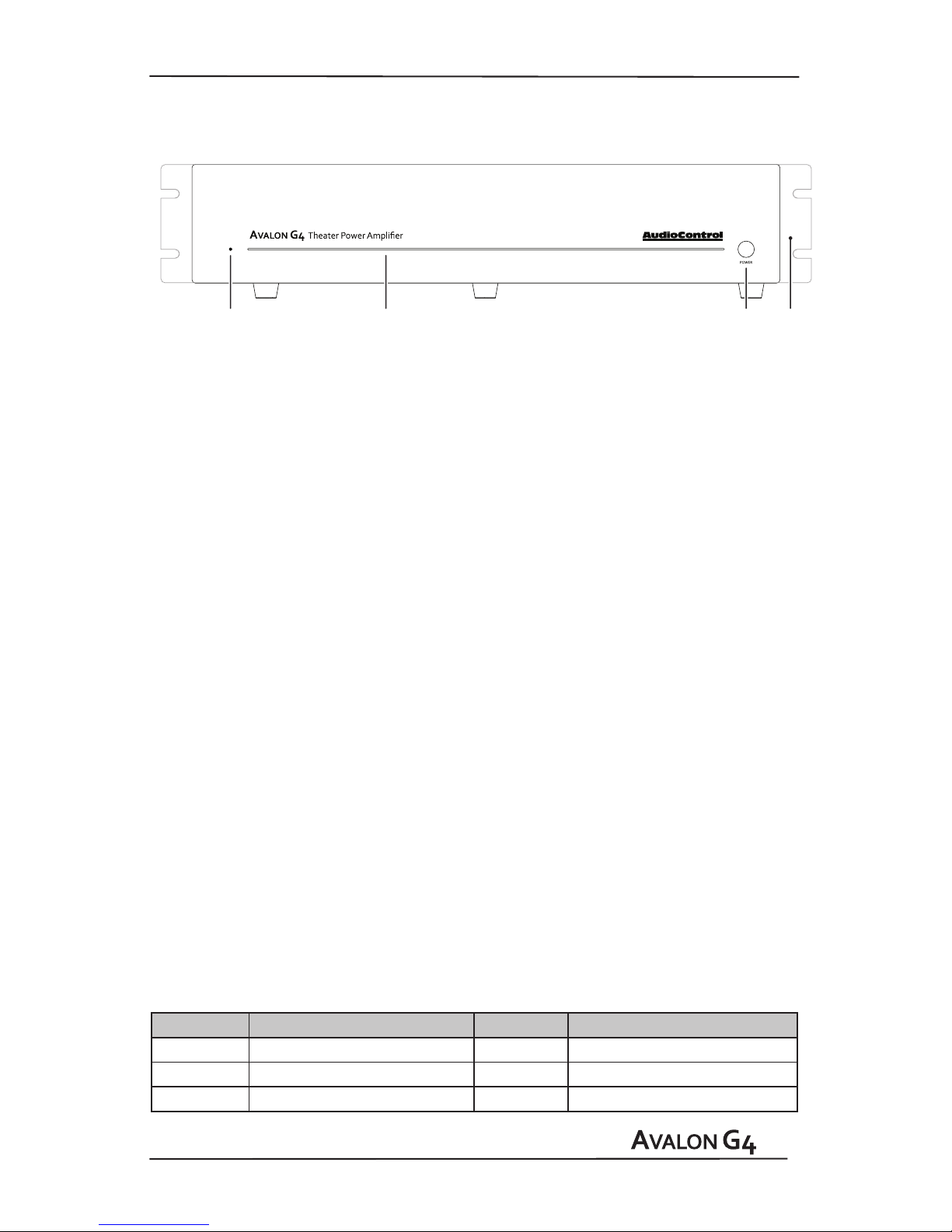
Front Panel Features
1. LED – On the far left of the heavy duty
brushed aluminum front panel, this
LED indicates the state of the Avalon
G4 amplier.
A Blue LED – shows that the amplier
is on and will drive your speakers when
the source is played.
A Red LED – shows that the amplier
is in standby mode, and will not drive
the speakers (hit the power button to
make it blue).
No LED illumination – means that it’s
either unplugged from wall power or
the back panel mains power switch is
turned o, or all the lights are out in
your town again.
Yellow LED – indicates initiation of
jump to hyperspace. You have ten
seconds to put the cat out, and leave
a note for the milkman. (Not yet avail-
able in this galaxy.)
2. Light bar – This front panel blue
light bar is mined directly from the
R- Coronae Australis Nebula. The brilliance of this light can be customized
via a button on the back panel.
3. Power Button – This large legendary
button allows for the on/standby mode
to be toggled. Press to turn the unit on
and press again to turn the unit into
standby mode. The rear panel Main AC
Power switch must be engaged for this
button to work.
4. RackMountEars– These optional
rack ears allow the unit to be rack
mounted in a standard 19” wide rack,
with a 2U height. Use standard rack
mount screws and washers to secure
the unit in a rack. The unit does not
have to be supported at the rear if the
rack is located in a xed location.
To remove the rack ears (making the
unit 17” wide), rst unplug the power
cord, and then locate and undo the
screws securing each ear to the side
of the chassis, and remove the ears.
Replace the screws securely back into
the chassis. Do not remove any of the
other screws from the chassis or top
cover. There are hazardous voltages
inside the unit. Keep the rack ears
safely tucked up in your sock drawer.
You can also remove the feet for rack
mounting, but remember to put them
back on if you are no longer in a rack.
LED Function Table
LED Color Description LED C0lor Description
Blue The unit is on Bright Red DC Error
Red The unit is in standby mode Dim Red Standby
O The unit is powered o
12 43
 Loading...