

AudioControl ARCHITECT MODEL 2660, ARCHITECT P2260, ARCHITECT P2280 EQ, ARCHITECT 2260, ARCHITECT P2680 EQ Installation Manual
...
ARCHITECT
™
MODEL 2660
16 CHANNEL MULTI-ZONE POWER AMPLIFIER
Installation Manual
2
3
Installation Manual
Model 2660
ARCHITECT
™
Important Safety
Instructions
1. Read these instructions.
2. Keep these instructions.
3. Heed all warnings.
4. Follow all instructions.
5. Do not use this apparatus near water.
6. Clean only with a dry cloth.
7. Do not block any ventilation openings. Install in accordance with the manufacturer’s
instructions.
8. Do not install near any heat sources such
as radiators, heat registers, stoves, or
other apparatus (including ampliers) that
produce heat.
9. Protect the power cord from being walked
on or pinched particularly at plugs, convenience receptacles, and the point where
they exit from the apparatus.
10. Only use attachments/accessories speci-
ed by the manufacturer.
11. Unplug this apparatus during lightning
storms or when unused for long periods of
time.
12. Refer all servicing to qualied service
personnel. Servicing is required when
the apparatus has been damaged in any
way, such as power-supply cord or plug is
damaged, liquid has been spilled or objects
have fallen into the apparatus, the apparatus has been exposed to rain or moisture,
does not operate normally, or has been
dropped.
13. This apparatus shall not be exposed to
dripping or splashing, and no object lled
with liquids, such as vases or glasses, shall
be placed on the apparatus.
The lightning ash with arrowhead
symbol within an equilateral triangle
is intended to alert the user to the
presence of uninsulated “dangerous voltage”
within the product’s enclosure, that may be
of sucient magnitude to constitute a risk of
electric shock to persons.
The exclamation point within an
equilateral triangle is intended to alert
the user of the presence of import-
ant operating and maintenance (servicing)
instructions in the literature accompanying the
appliance.
Caution: to reduce the risk of electric shock,
do not remove the top cover. There are no
user-serviceable parts inside. Refer servicing to
qualied personnel.
This equipment has been tested and found
to comply with the limits for a Class B digital
device, pursuant to part 15 of the FCC Rules.
These limits are designed to provide reasonable
protection against harmful interference in a
residential installation.
This equipment generates, uses, and can radiate radio frequency energy and, if not installed
and used in accordance with the instructions,
may cause harmful interference to radio communications. However, there is no guarantee
that interference will not occur in a particular
installation.
If this equipment does cause harmful interference to radio or television reception, which can
be determined by turning the equipment o
and on, the user is encouraged to try to correct
the interference by one or more of the following measures:
• Reorient or relocate the receiving antenna.
• Increase the separation between the equipment and the receiver.
• Connect the equipment into an outlet on
a circuit dierent from that to which the
receiver is connected.
• Consult the dealer or an experienced radio/
TV technician for help.
CAUTION: Changes or modications to this
device not expressly approved by AudioControl
Inc. could void the user’s authority to operate
the equipment under FCC rules.
Recycling notice: If the time comes
and this apparatus has fullled its
destiny, do not throw it out into the
trash. It has to be carefully recycled
for the good of mankind, by a facility specially
equipped for the safe recycling of electronic
apparatii. Please contact your local or state
recycling leaders for assistance in locating a
suitable nearby recycling facility. Or, contact us
and we might be able to repair it for you.
Table of Contents
Table of ContentsImportant Safety Instructions
Important Safety Instructions .......2
Introduction .......................4
Congratulations! ..................4
Features .........................5
Complimentary bullet points ........6
Quick View .......................7
Getting Started ....................8
An Important note about Triggering ..8
Home Installation .................9
Commercial Installation ............9
Front Panel Features ...............10
Ventilation .......................11
LED Function Table ................11
Rear Panel Features ................12
AC section ......................12
Bus A and B Sections ...............14
DIP Switch Function Table ..........15
Speaker Connections ...............17
Speaker and Wiring Impedance ......18
Troubleshooting ...................19
Block Diagrams ....................21
Specications ......................23
Service ............................24
The Warranty ......................25
Installation Notes .................27
Basic Cha Cha ......................28
©2015 AudioControl Inc All rights reserved.
Only Union Stunt Ferrets were used during the ght scene in this manual.
4
5
Installation Manual
Model 2660
ARCHITECT
™
Flowery Marketing Introduction
Features
When a whole-house audio system demands high levels of audio performance,
but the physical installation space is
limited, the AudioControl Architect Model
2660 is an ideal solution. Requiring only
two rack spaces, this 16 channel power
amplier produces at least 65 Watts per
channel into 8 Ohms, and 100 Watts per
channel into 4 Ohms, with all channels
driven. Extensive protection features prevent damage to your loudspeakers.
Congratulations!
You are now installing a component which
will dramatically improve the performance
of any distributed audio system, especially those utilizing in-wall, in-ceiling, and
invisible speakers.
The Architect Model 2660 16 channel
power amplier provides high levels of
power, pristine sound quality, exible
input switching, plus a number of installation-friendly features that makes it the
perfect product for performance oriented
audio systems. The Architect Model 2660
is an American-designed and built, “set
Features
Here are some of the features that make
the Architect Model 2660 a very unique
product, unlike any other amplier:
• Superior Sound Quality
Pristine sonics happens rst in all
AudioControl designs and is not
compromised by any other feature.
(You often get the feeling that sound
quality is an afterthought with prod-
ucts from other companies.)
• High Power Levels
There are 16 channels of 65 Watts
each into 8 Ohms, or 100 Watts into 4
Ohms. Each channel pair can also be
run in bridged mono at 175 Watts into
8 Ohms. Each high-eciency amplier is discretely made from discrete
components.
• Bussable Digital and Analog Inputs
Each zone can select either Bus A,
Bus B, or a local input. The Bus A S/
PDIF digital input uses a high resolution DAC that converts up to 192 kHz.
The digital source is available to play
in any zone. The Bus B analog input
uses a pair of RCA connectors. The
analog source is available to play in
any zone. A pair of RCA connectors
is also available as a loop output, for
example: to share the source with an-
other Architect Model 2660 amplier.
Each zone has its own local pair of
analog input connectors.
• Unparalleled Energy Eciency
Whether from the point of view of
saving electricity, or from the viewpoint of less heat in the rack, the
Architect Model 2660 amplier has
no equal. It is VERY energy ecient
during operation, and equally impressive during standby.
Introduction
and forget” component which will provide
a lifetime of trouble-free service for your
multi-room audio system.
The Architect Model 2660 is designed and
manufactured by AudioControl, the only
electronics company in the world that
specializes in ampliers, equalizers, signal
processors and audio analyzers. Our passion for high quality, meticulous attention
to detail, and pro sound heritage shows
itself in the dozens of awards we have won
for our designs, products, and service.
Now, as when we began, our greatest
satisfaction is our reputation for sonic
excellence and reliability among people
just like you throughout the world.
This manual is designed to help you get
the best out of this amplier. So, even
though you’re dying to see it in action,
please take a few minutes to slog through
our not-so-weighty prose and learn how
to get the most from your Architect power
amplier.
• LightDrive Anti-clipping
With durability in mind, AudioControl’s LightDrive anti-clipping protection defends the system against clipping, distortion, damage, and even
teenage parties. The Architect Model
2660 features the latest evolution of
LightDrive which adds a power-supply-tracking instantaneous dynamic
control to the smooth sound of the
traditional AudioControl LightDrive.
• Self Resetting Protection Features
Protection features are extensive and
include thermal, short circuit, clip-
ping, ultrasonic and DC oset among
others. If the fault is removed, the
Architect Model 2660 resets.
• Pacic Northwest Heritage
Hard to believe, but we make this
product in the USA. We are very
proud of that fact. What is more important is the care we craft in at every
step, and the extensive knowledge
we have in all aspects of the product.
Plus, we back this up with a condi-
tional ve year warranty.
6
7
Installation Manual
Model 2660
ARCHITECT
™
Complimentary bullet points
Features continued
Quick View
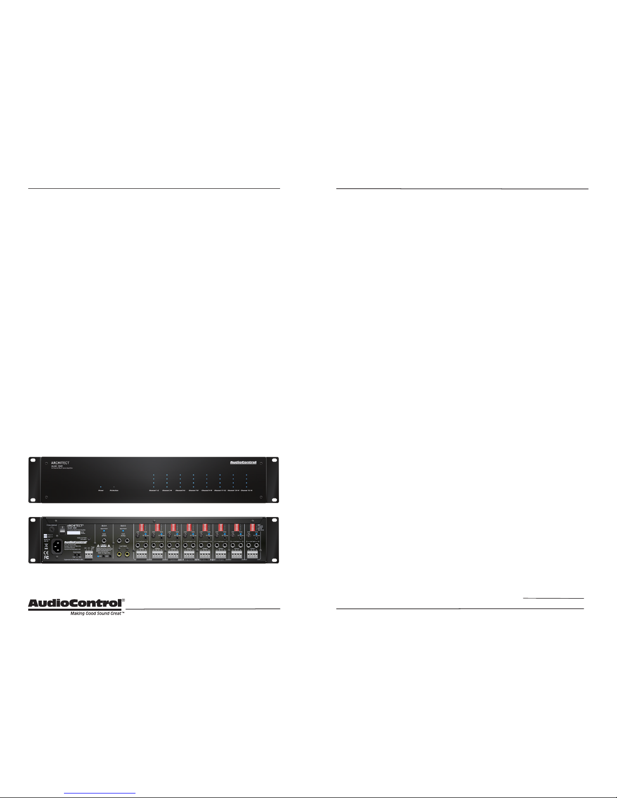
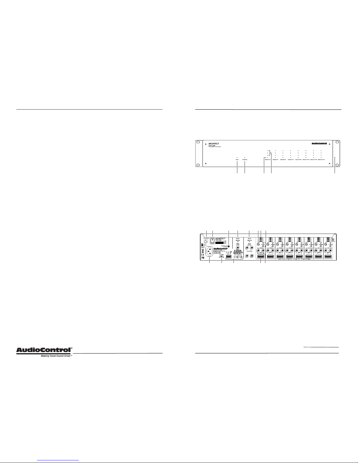
Quick View
Front Panel
4. Zone Level LED Ladder
5. Rack Mount Ears
Rear Panel
9. Zone Level Control
10. DIP Switches
1 Mono/Stereo
2 PFM 40 Hz
3 Local/Bus
4 Bus A/B
5 Signal Sense
11. 12V Local Trigger
12. Local Analog Inputs
13. Speaker Outputs
6 13121 4
72 3 5 8 910 11
1 2 3 54
• 16 channels of AudioControl
amplication
• Ecient power ampliers and power
supplies
• Power consumption is less than 0.5
Watts in standby
• Rack mountable 2U form factor
• Removable rack ears
• Light weight (16 lbs)
• Stackable with other Architect Model
2660 and Director Matrix M6400 models
• Signal sense independent for each zone
• Bus assignment independent for each
zone
• 40 Hz infrasonic lter independent for
each zone
• 12V Trigger independent for each zone,
usable with contact closure or 12V
external source
• 12V Master trigger
• BUS A S/PDIF input with premium
Wolfson digital to analog converter
• BUS B analog input pair with loopthrough outputs
1. AC Input
2. AC Fuse
3. AC Power Switch
4. Ground Isolation Switch
5. Disable Front Panel LED Ladders
6. Master Trigger
7. BUS A Digital Input
8. BUS B Analog Input and Loop
Output
1. Power LED
2. Protection LED
3. Zone Status LED
8
9
Installation Manual
Model 2660
ARCHITECT
™
Getting Started
1. Turn o power to all components before making any
connections.
2. When making connections, des-
ignate red RCA plugs as right, and
designate white, black, or grey plugs
as left. This is a good idea for all signal connections made in your audio
system. The key is consistency. Stick
with the same color coding and you’ll
reduce possible problems.
3. Whenever possible, keep power
cords away from signal cables to prevent induced hum. This is especially
important if you bundle the cables to
keep the installation neat looking.
4. Use quality interconnect cables. We
know from experience that really
cheap cables can cause a multitude
of problems. They tend to break
inside or corrode, causing a loss of
signal or hum. They also have poor
shielding.
5. If you need to run the RCA audio
cables more than 20 feet, consider
using an active balanced line driver
for the signals. This will provide
better noise rejection against nasty
things like hum, spikes, local talk
radio, and metaphysical paranormal
phenomena, etc. The AudioControl
balanced line driver components
(BLD-10, BLR-10 and BLX-10) are an
excellent way to send audio over long
distances with standard Cat-5 wiring.
Check them out at audiocontrol.com.
6. If you are using the Bus A digital
input, and running higher resolution
sample rates (96 kHz - 192 kHz), use
high-quality interconnect cables.
Getting Started
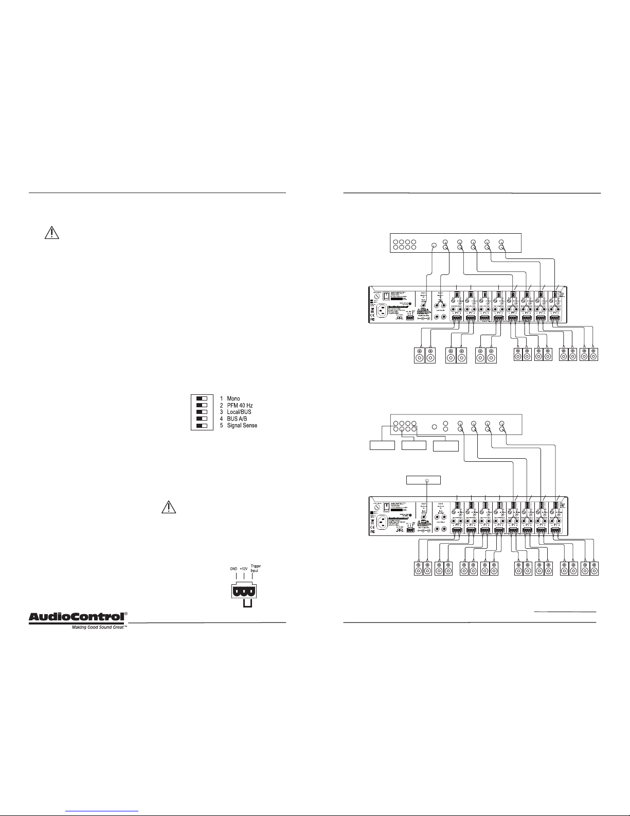
Installation Examples
Home Installation
Commercial Installation
Garage
Zone
Art Studio
Zone
Pool
Zone
Patio
Zone
Source
Inputs
Analog Source
Outputs
Digital Source
Output
Living
Dining
BUS A BUS B BUS B local local local local
Family
Whole House
Audio System
Controller
Source Inputs
Background Music Source
(CD, DVD, MP3, or TV)
Source Units for Room Zones
CD Player Satellite
Music
Server
Analog Source Outputs
BUS A local local local local
Room Zones
Multiple Sources
Background Speakers
One Source Only
Whole House
Audio System
Controller
BUS A BUS A BUS A
Installation Examples
The next page shows two examples of
typical Architect Model 2660 installations.
The rst example is a home installation
with four separate zones, each playing a
dierent local analog source. Two other
zones are playing the Bus B analog source,
and one is playing the Bus A digital source.
The second example is a bar or restaurant
installation where multiple speakers in the
main seating area are playing the Bus A
digital source, and separate room zones
are playing individual local analog sources.
The versatile DIP switches of each zone
allow the selection of the local inputs, BUS
A input, and BUS B input to play in that
zone.
An Important Note about Triggering
The Architect Model 2660 master trigger
connectors (two TS 1/8” and a 3-pin block)
are used to turn on the unit or place it into
standby mode.
If no trigger voltage is present at
any of these trigger inputs, then
the unit will be in standby, with all
zones muted. If you are not using master
triggering, then you must install a short
wire link from the 12V output pin to the
trigger input pin of the 3-pin connector.
To put the unit into
standby, remove the
link.
Wire Link
 Loading...