

Page 1
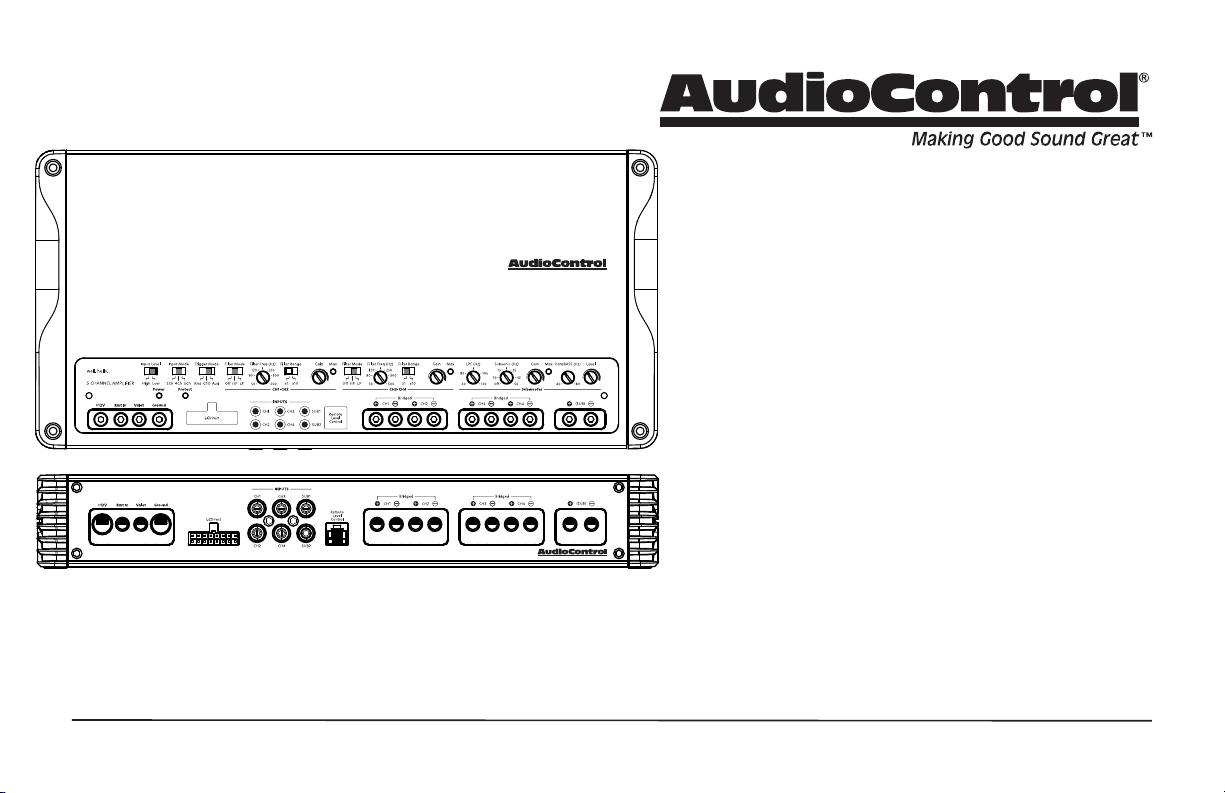
A1100.5
A1100.5
Features
• 4 x 90 W @ 4 Ohms + 1 x 400 W @ 4 Ohms
• 4 x 125 W @ 2 Ohms + 1 x 600 W @ 2 Ohms
• 6 RCA Line Inputs
• GTOTM Signal Sense
• Audio Sense
• Independent -12 dB Linkwitz-Riley Crossovers
• Optional wired ACR-1 Remote Control for Subwoofer Level
• Subsonic Filter -24 dB Linkwitz-Riley
• ParaBASS® Low Frequency Contouring
• Valet Mode Enabled
• LC Direct High Level Input
• Start-stop compliant
• EV compliant up to 17V
• Sleek Chassis Design
• Power House
A1100.5
Five Channel Amplier
Quick Start Guide
Page 2
Important Safety Instructions
2
A1100.5
1. Read these instructions.
2. Keep these instructions.
3. Heed all warnings.
4. Follow all instructions.
5. Do not use this apparatus near water.
6. Clean only with a dry cloth.
7. Do not block any ventilation openings. Install in accordance with the
vehicle manufacturer’s instructions.
8. Do not install near any heat sources such as muers, silencers, exhaust
pipes, or other apparatus (including ampliers) that produce heat.
9. WARNING: Improper installation may lead to permanent injury or death.
Installation of the apparatus must be done with great care by qualied
personnel, to prevent damage to fuel lines, power, and other electrical
wiring, hydraulic brake lines, and other systems, that might compromise
vehicle safety.
10. Provide +12V and Ground insulated wiring of 4 AWG to ensure
adequate current to the amplier.
11. Use rubber grommets to protect wiring whenever passing wires through
metal openings or bulkheads.
12. Only use attachments/accessories specied by the manufacturer.
13. Refer all servicing to qualied service personnel. Servicing is required
when the apparatus has been damaged in any way, such as the power input terminals are damaged, liquid has been spilled or objects have fallen
into the apparatus, the apparatus has been exposed to rain or moisture,
does not operate normally, or has been dropped.
14. This apparatus shall not be exposed to dripping or splashing, and no
object lled with liquids, shall be placed on the apparatus.
15. Fuses inside the fuse holder at the battery shall be replaced only with the
correct type and fuse value, and only when the apparatus is powered o.
16. Exposure to high sound pressure levels may lead to permanent hearing
loss. Take every precaution to protect your hearing.
The lightning ash with arrowhead symbol within an equilateral
triangle is intended to alert the user to the presence of uninsulated
“dangerous voltage” within the product’s enclosure, that may be of
sucient magnitude to constitute a risk of electric shock to persons.
The exclamation point within an equilateral triangle is intended to
alert the user of the presence of important operating and maintenance (servicing) instructions in the literature accompanying the
appliance.
Caution: to reduce the risk of electric shock, do
not disassemble the apparatus, other than to
remove the top panel to access the controls.
There are no user-serviceable parts inside. Refer
servicing to qualied personnel.
Recycling notice: If the time comes and this apparatus has fullled
its destiny, do not throw it out into the trash. It has to be carefully
recycled for the good of mankind, by a facility specially equipped
for the safe recycling of electronic apparatii. Please contact your
local or state recycling leaders for assistance in locating a suitable
nearby recycling facility. Or, contact us and we might be able to
repair it for you.
Quick Start Guide
Page 3
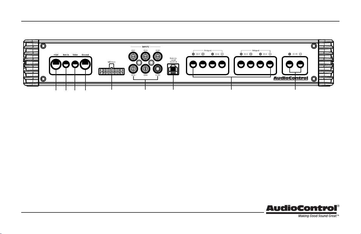
Connection Panel Features
A1100.5
1 2 3 4 5 6 7 8 9
1. Power Input Terminal +12V – This screw terminal connects to
the +12V battery binding post of the vehicle. Use quality insulated
4 AWG wire.
2. Remote Power Input Terminal – This screw terminal connects to
the 12V remote trigger output of some head units. When the head
unit is turned on, then the A1100.5 will turn on.
3. Valet Mode Connection - This screw terminal connects to an optional switch to lower the max volume to 25% when switched on.
4. Power Input Terminal Ground – This screw terminal connects to
a good ground connection on the vehicle. Use quality insulated 4
AWG wire.
5. LC Direct – The speaker-level output (20V MAX) from ampliers
and factory installed radios can connect here. Do not use these
inputs if you are using the RCA line-level inputs.
6. RCA Analog Line-Level Inputs – The line-level output from an
aftermarket head unit can connect here. Do not use these inputs if
you are using the speaker-level inputs (LC Direct).
7. Remote Level Control (optional) – This port connects to the
ACR-1 remote level control.
8. Speaker-Level Output Terminals – These screw terminals
connect with speaker wire to your loudspeakers. Make sure that
the average combined speaker impedance does not dip below
2 Ohms, or 4 Ohms in bridged mono mode.
9. Subwoofer-Level Output Terminals – These screw terminals
connect with speaker wire to the subwoofer, or multiple subwoofers. Make sure that the speaker impedance does not dip below 2
Ohms.
3
Page 4
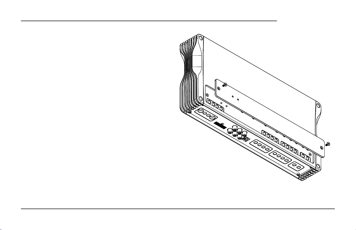
Top Cover Removal
The top cover must be removed to gain access to the controls, and
then put back on again to protect the controls from dust bunnies.
Removal Procedure
1. Locate the two screws holding the top cover on the amplier.
2. Use the supplied hex key to loosen both screws just enough until the edge of the cover can lift freely up just a little. (There is no
need to remove the screws all the way, in case you lose them.)
3. Lift the cover o of the amplier.
4. Place the cover in a safe and handy place, ready for the time
when you have nished adjusting the controls to your immense
satisfaction, and just before Alfred brings tea and sandwiches.
4
A1100.5
Quick Start Guide
Page 5
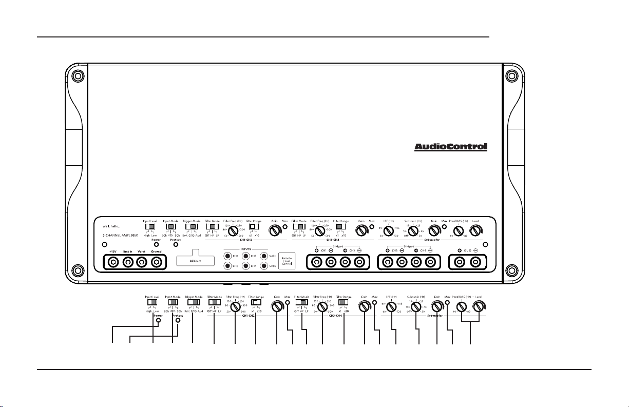
Control Panel Features
A1100.5
5
A1100.5
10 11 12 13 14 15 16 17 18 19 20 21 22 23 24 25 26 27 28 29
Quick Start Guide
Page 6

10. Power LED - If you have connected your battery power, vehicle
ground, and turn-on lead (or used an alternative signal sensing
turn on mode correctly), then this light should be illuminated
white to indicate the amplier is powered ON.
11. Protection LED – If this LED illuminates red, this signies the
amp is in protection mode and something is wrong. If cycling
the power to the amplier does not take amp out of protection
then disconnect speaker wires and cycle power. If the amp is no
longer in protection then check speaker and wires for shorting.
If light stays on with speaker wires disconnected then contact
AudioControl Technical support for further instruction. If the LED
illuminates amber, this signies the amp is in Valet Mode.
12. Input Level Switch – High (LC Direct) = 1.5-20 volts, Low (RCA)
= 0.5 -6 volts. Select High for most systems using a factory stereo
as the source. Select Low for most systems using an aftermarket
source unit, LOC, or DSP.
13. Input Mode Switch – Select 2ch when only one pair of RCA and
input signal is available. This will route signal from inputs 1&2 to
all 5 output channels. Select 4ch when all four channels of input
are present/available. This will route signal from inputs 1&2 to
Ch 5 output channels Select 5ch when all ve channels of input
are present/available. Signal will be routed from each input to its
corresponding output
14. Remote / GTO / Audio – (Rmt) Select this mode when the re-
mote turn-on signal from an aftermarket head-unit, LOC, or DSP
is present to turn the amp ON. (GTO™) for Ch 1 High Level Input
Only: Choose this mode when no turn on signal is available, and
the amplier will gracefully turn on when it detects your source
unit powering up, then turn o after the source unit powers
down, (Aud) When this mode is selected, the amplier will turn
ON when it detects audio signal from Ch 1 is present on the
inputs, regardless of the source. If you turn the head unit on, but
DON’T play audio, the amplier will not turn on when using this
turn on mode.
15. Filter Mode OFF/HP/LP - OFF: crossover is disengaged, allowing all frequencies (full range signal) to play through output
channels 1&2. HP: the amplier will limit output to allow only
frequencies higher than the chosen crossover frequency to play
through output channels 1&2. This protects smaller speakers
from playing low frequency signals that they can’t physically
reproduce without distortion or damage. LP: the amplier will
limit output to allow only frequencies lower than the chosen
crossover frequency to play through output channels 1&2. This
prevents larger speakers from playing high frequency signals
that they were not designed to accurately reproduce.
16. Filter Freq (Hz) – The crossover adjustment pot selects the frequencies that output channels 1&2 of your A1100.5 will play. Use
to adjust the cuto frequency depending on what speakers are
connected to outputs 1&2.
6
Page 7

A1100.5
7
17. Filter Range x1 / x10 When set to x1, the selected crossover
frequency is applied exactly as chosen. (i.e. If 80hz was chosen
and switch is set to x1, then 80 Hz will be the crossover point.)
x1 is typically used for crossing over larger midbass or subwoofer
channels. When set to x10, the selected crossover frequency
is multiplied by 10x then applied. (i.e. If 80hz was chosen and
switch is set to x10, then 800hz will be the crossover point.) x10
is typically used for crossing over midrange or high frequency
speaker channels.
18. Gain – Use this dial to match the source unit’s output voltage
with the inputs of amplier channels 1 & 2. Remember, this is
NOT a volume knob.
19. Max. Indicator – This LED indicates when channels 1&2 have
been optimized for maximum performance. This LED should
illuminate momentarily during brief bursts of music playback
at max volume. In most scenarios, it should not be constantly
illuminated for long periods of time.
20. Filter Mode OFF/HP/LP - OFF: crossover is disengaged, allowing all frequencies (full range signal) to play through output
channels 3&4. HP: the amplier will limit output to allow only
frequencies higher than the chosen crossover frequency to play
through output channels 3&4. This protects smaller speakers
from playing low frequency signals that they can’t physically
reproduce without distortion or damage. LP: the amplier will
limit output to allow only frequencies lower than the chosen
crossover frequency to play through output channels 1&2. This
prevents larger speakers from playing high frequency signals
that they were not designed to accurately reproduce.
21. Filter Freq (Hz) – The crossover adjustment pot selects the frequencies that output channels 3&4 of your A600.4 will play. Use
to adjust the cuto frequency depending on what speakers are
connected to outputs 3&4.
22. Filter Range x1 / x10 When set to x1, the selected crossover
frequency is applied exactly as chosen. (i.e. If 80hz was chosen
and switch is set to x1, then 80hz will be the crossover point.)
x1 is typically used for crossing over larger midbass or subwoofer
channels. When set to x10, the selected crossover frequency
is multiplied by 10x then applied. (i.e. If 80hz was chosen and
switch is set to x10, then 800hz will be the crossover point.) x10
is typically used for crossing over midrange or high frequency
speaker channels.
23. Gain – Use this dial to match the source unit’s output voltage
with the inputs of amplier channels 3 & 4. Beating a dead horse
here but remember… this is NOT a volume knob!
24. Max. Indicator – This LED indicates when channels 3&4 have
been optimized for maximum performance. This LED should
illuminate momentarily during brief bursts of music playback
at max volume. In most scenarios, it should not be constantly
illuminated for long periods of time.
Quick Start Guide
Page 8

25. Low Pass Crossover – A crossover allows you to match a speaker
to the frequency range it is designed to handle. Choosing the
crossover point recommended by the speaker manufacturer will
provide increased speaker reliability and optimum sound quality.
The A1100.5 amplier has selectable low pass crossover frequencies at 60Hz-120Hz. The amplier reproduces the frequency
range below the selected crossover frequency.
26. Subsonic Filter – The Subsonic lter is normally used on a
vented subwoofer enclosure. Recommended setting is one
octave below the enclosure tunning frequency.
27. Gain – Use this dial to match the source unit’s output voltage
with the inputs of amplier Ch 5. Remember, this is NOT a volume knob.
28. Max. Indicator – This LED indicates when channels 1&2 have
been optimized for maximum performance. This LED should
illuminate momentarily during brief bursts of music playback
at max volume. In most scenarios, it should not be constantly
illuminated for long periods of time.
29. ParaBASS® Two simple controls allow for killer bass tweaking.
The ParaBASS (Hz) knob selects the center frequency, between
40 Hz and 80 Hz. The level knob provides you to 10 dB of boost
centered around the ParaBASS® frequency.
ACR-1 (Optional)
ACR-1 remote
The optional AudioControl ACR-1 dash control is a remote level
control for your A1100.5 amplier. It may be mounted under the
dash using its own enclosure, or through a custom hole in the
dash. The level control knob should be within reach of the driver,
and in a spot where the LED is plainly visible. Insure the amplier
is powered o when connecting the ACR-1.
Dash Bracket Installation: The dash control mounts with two screws,
which attach to the underside of the dashboard. Slide under the
dash and place the dash control in its mounting position, mark
the two best mounting holes, drill pilot holes, and secure with two
screws.
Custom Installation: For that custom, nished look, the dash control
can be ush-mounted directly on the dashboard (or anywhere
else). See ACR-1 manual/packaging for details and diagram.
The long-awaited moment when “plethora” is used in a manual
The plethora of A1100.5 controls allows for a wide variety of in-
stallation possibilities. This quick start guide gives a few examples
of system diagrams reference (pages 11-13) and includes a few
notes about the control settings for each one.
Note: The technical writer reserves the right to be wrong about things, due to the
cold medicine being the night-time sleepy stu, and not the usual day-time strength.
8
Page 9

9
Quick Start
Here are a few general steps to get your A1100.5 amplier up and
running:
1. Undo the +12V and Ground connections to the car battery
before making any connections to the amplier.
2. Pick a mounting location that will provide access to the controls
and connections, provide adequate ventilation, and also protect
the amplier from heat, moisture, and dirt. Make sure that the
heat-sink ns are not covered.
3. The A1100.5 amplier needs to be securely mounted using the
four mounting holes located in each corner.
4. Before drilling any holes, take every precaution to prevent any
damage to fuel lines, power and other electrical wiring, hydraulic
brake lines, and other systems, that might compromise
vehicle safety.
5. When making connections, designate red RCA plugs as right,
and designate white, black, or grey plugs as left. This is a good
idea for consistency.
6. Use quality interconnect cables.
7. Always connect the amps Ground terminal rst before connecting the 12V power wire to the amp. Not following these instructions could result in damaging the amp and this would not be
covered under warranty. Also NEVER REMOVE THE GROUND
WIRE from the amp while the 12V wire is connected.
A1100.5
8. Connect the Ground terminal of the unit to the chassis of the vehicle, using 4 AWG wire. Connect the +12V wire using the same
gauge wire as the ground wire.
9. Connect the remote power terminal of the amp to the remote
turn-on output of your source unit. Alternatively, you can skip
this connection and use the GTO / Aud turn-on method.
10. Connect your audio inputs to the unit – either speaker-level or
line-level RCA… not both.
11. Run the optional ACR-1 remote to the front of the vehicle to
adjust the output level on the y.
12. Connect your loudspeakers (2 Ohm stereo, 4 Ohm Bridged minimum load).
13. Once all connections are made, reconnect the vehicle battery.
14. Adjust your input source gain using the MAX Clip LED. When the
Audio is playing look at the light and when the music peaks the
light should ash.
15. Set the A1100.5 crossovers to the frequency recommended by
the loudspeaker manufacturer.
16. Adjust the Subsonic lter when using a vented enclosure.
17. Enjoy the drive!
Quick Start Guide
Page 10
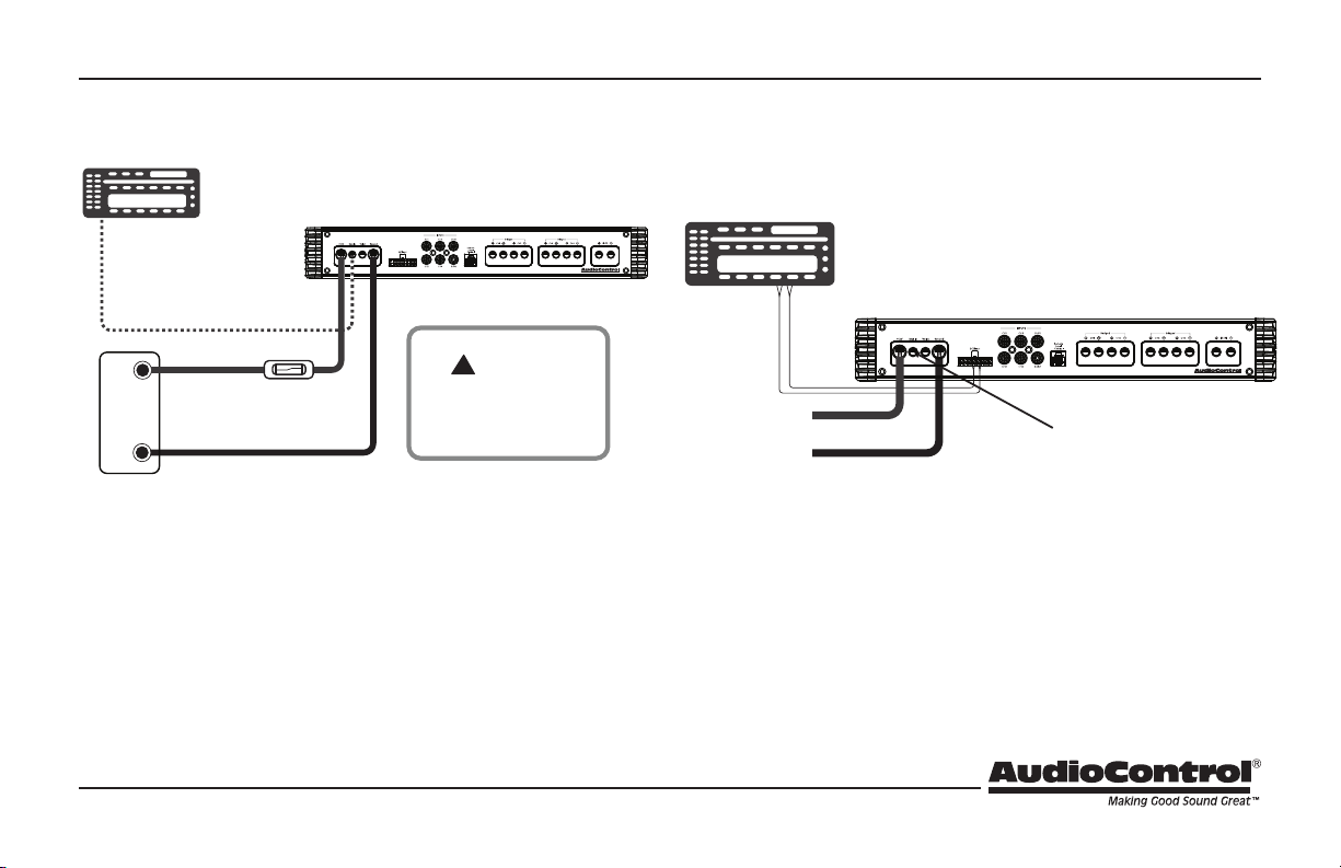
Power Connections
Head Unit
Remote Amplifier
+12V Trigger
A1100.5
+
+12V
Battery
-
Ground
Fuse
Fuse Specications is
located on page 15
Caution
!
A 125 amp external fuse
must be added to the
Positive (+) wire.
In this example, the head unit has a +12V trigger output that is
connected to the A1100.5 remote input terminal. When the head
unit is turned on, it will turn on the A1100.5 amplier.
Use 4 AWG insulated wire for the +12V and Ground connections.
Head Unit
+12V
A1100.5 turns on using GTO on inputs 1.
A1100.5
No remote turn on wire is needed
Ground
In this example, the GTO signal sense feature can be used to gently
turn on the A1100.5 amplier when an audio input signal is detected on inputs 1.
10
Page 11
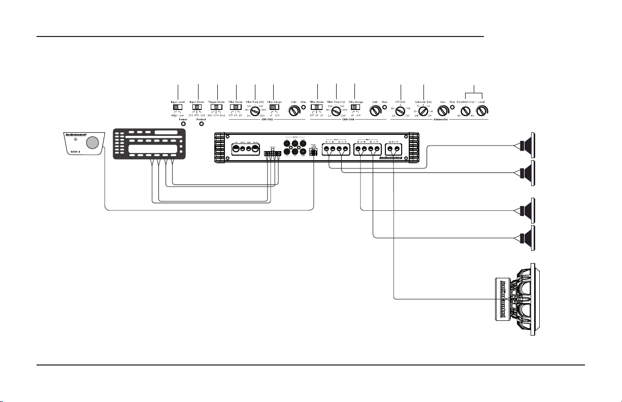
System #1: Adding Front/Rear Speakers + Sub to a Factory Radio
HP
80 Hz
High
4 Ch
HP
80 Hz
GTO
x 1
x 1
O
80 Hz
11
A1100.5
*
Front Speakers
ACR-1
(Optional)
Notes:
The +12V Power and Ground connections are not shown.
• Input Level: Input level is set to High.
• Trigger mode: Set the trigger mode to GTO.
• Filter mode channel 1/2 is set to HP.
• Filter frequency channel 1/2 is adjusted to 80Hz.
• Filter range channel 1/2 is set to x1.
• Filter mode channel 3/4 is set to HP.
• Filter frequency channel 3/4 is adjusted to 80Hz.
• Filter range channel 3/4 is set to x1.
• LPF (Hz): Set the LP lter to 80 Hz.
• Subsonic (Hz): Set the Subsonic to O for sealed enclosures and On for vented.
• ParaBASS® (*) : If you notice a deciency in your bass response output, you can use the
ParaBASS® feature to dial into a specic frequency and boost the response back to your liking.
Factory
Radio
Rear Speaker-level output
Front Speaker-level output
A1100.5
Rear Speakers
Subwoofer
Quick Start Guide
Page 12
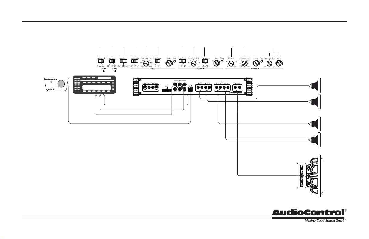
System #2: Adding Front/Rear Speakers + Sub to an Aftermarket Radio
HP
80 Hz
HP
80 Hz
Low
4 Ch
Rmt
x 1
x 1
O
80 Hz
*
Front Speakers
ACR-1
(Optional)
Aftermarket
Radio
Subwoofer Low-level output
Rear Low-level output
Front Low-level output
A1100.5
Notes:
The +12V Power and Ground connections are not shown
• Input Level: Input level is set to Low.
• Trigger mode: Set the trigger mode to Rmt.
• Filter mode channel 1/2 is set to HP.
• Filter frequency channel 1/2 is adjusted to 80Hz.
• Filter range channel 1/2 is set to x1.
• Filter mode channel 3/4 is set to HP.
• Filter frequency channel 3/4 is adjusted to 80Hz.
• Filter range channel 3/4 is set to x1.
• LPF (Hz): Set the LP lter to 80 Hz.
• Subsonic (Hz): Set the Subsonic to O for sealed enclosures and On for vented.
• ParaBASS® (*) : If you notice a deciency in your bass response output, you can use the
ParaBASS® feature to dial into a specic frequency and boost the response back to your liking.
Rear Speakers
Subwoofer
12
Page 13
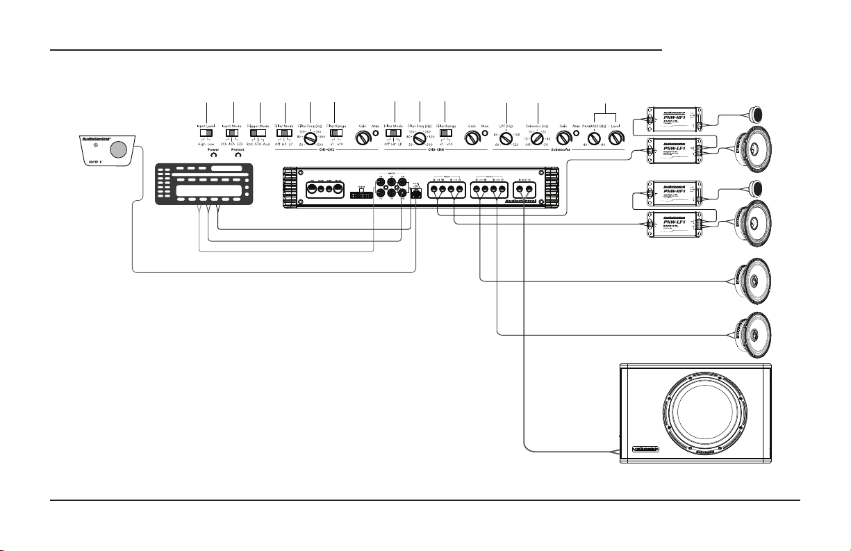
System #3: AudioControl 5 Channel System
Low
4 Ch
Rmt
ACR-1
(Optional)
Aftermarket
Radio
Notes:
Aftermarket Radio connected, using Line-level connection.
The +12V Power and Ground connection not shown.
• Input level is set to Low.
• Input mode is set to 5 Ch.
• Trigger mode is set to Rmt.
• Filter mode channel 1/2 is set to HP.
• Filter frequency channel 1/2 is adjusted to 80Hz.
• Filter range channel 1/2 is set to x1.
• Filter mode channel 3/4 is set to HP.
• Filter frequency channel 3/4 is adjusted to 80Hz.
• Filter range channel 3/4 is set to x1.
• LP lter is adjusted to 80 Hz.
• Subsonic is set to 29 Hz.
• Set Gain level right below Max clipping light.
• ParaBASS® (*) : If you notice a deciency in your bass
response output, you can use the ParaBASS® feature to
dial into a specic frequency and boost the response back
to your liking.
Subwoofer Low-level output
Rear Low-level output
Front Low-level output
HP
80 Hz
x 1
A1100.5
This system was designed using the
following AudioControl equipment:
• Amplier = A1100.5
• Front Speakers = PNW-65CS2
• Rear Speakers = PNW-65
• Loaded Enclosure = SPK-V10 or SPK-V12
HP
13
A1100.5
80 Hz
x 1
O
80 Hz
*
Woofers
Speaker-level output
80 Hz and below
Quick Start Guide
Page 14
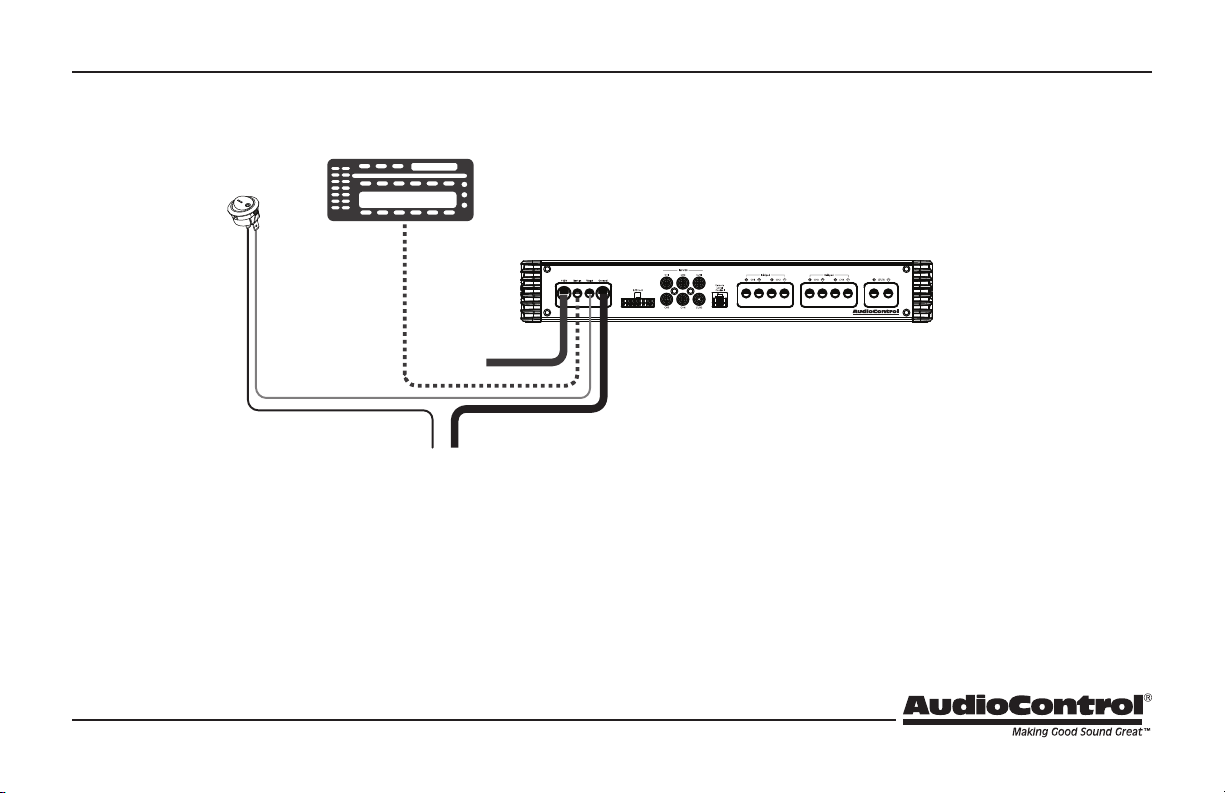
Ground
Valet Mode Connection
On/Off
Switch
Not Included
Head Unit
Remote Amplifier
+12V Trigger
+12V
Notes:
Connect a wire to the Valet terminal on the amplier.
Connect the other end to a On/O switch. (Any 2 prong On/O switch should work)
Connect the other open switch prong to chassis ground.
When the Valet switch is activated, the amplier limits maximum volume to 25%,
protecting your audio system from the wiles of the wayward but well-meaning valet.
A1100.5
14
Page 15

Specications
All specications are measured at 14.4 VDC (standard automotive voltage). As technology advances, AudioControl reserves the right to continuously change our specications, like our Pacic Northwest weather, although we are working on a surround-sound umbrella as well.
A1100.5 Multi-Channel Amplier
Power Output. . . . . . . . . . . . . . . . . . . . . . . . . . . . . . 4 x 90 Watts + 1 x 400 Watts @ 4 Ω
. . . . . . . . . . . . . . . . . . . . . . . . . . . . . . . . . . . . . . . . . . . 4 x 125 Watts + 1 x 600 Watts @ 2 Ω
. . . . . . . . . . . . . . . . . . . . . . . . . . . . . . 2 x 250 Watts @ 4 Ohm bridged Ch1&2, 3&4 only
S/N Ratio Channels 1,2,3,4. . . . . . . . . . . . . . . . . . . . . . .-95.1 dBA, Ref 90 Watts @ 4 Ω
S/N Ratio Channel 5 ...........................-103.9 dBA, Ref 400 Watts @ 4Ω
THD+N .....................................................< 0.25% & 0.75%
Power / Ground Wire Gauge ...........................................4 AWG
Crossover Channel 1/2, 3/4 . . . . . . . . . . . . . . . . . . . . . . . . . . . . . . -12 dB Linkwitz-Riley
. . . . . . . . . . . . . . . . . . . . . . . . . . . . . . . . . . . . . . . . . . . . . . . adjustable from 50 Hz to 5K Hz
Channel 5. . . . . . -12 dB/Octave Linkwitz-Riley, Adjustable From 60 Hz to 120 Hz
Subsonic ........ -24 dB/Octave Linkwitz-Riley, Adjustable From 0 Hz to 50 Hz
Speaker-Level Inputs. . . . . . . . . . . . . . . . . . . . . . . . . . . . . . . . . . . . . . . . . . . . . . . .20 V max
Line-Level Inputs. . . . . . . . . . . . . . . . . . . . . . . . . . . . . . . . . . . . . . . . . . . . . . . . . . . . . 6 V max
Recommended Fuse rating. . . . . . . . . . . . . . . . . . . . . . . . . . . . . . . . . . . . . . . . . . . . . 120A
Weight ..............................................................7.95 lbs
Dimensions .............................................14” W x 6.7” D x 2.1 H
©2024 AudioControl. All rights reserved.
For more information about this ne product, and for details of the limited warranty, and
repair services, please visit our website at
www.audiocontrol.com
All specications are subject to being covered in honey without notice.
AudioControl
For more information about this ne product, and for technical
questions, additional details of the limited warranty and repair services,
please visit www.audiocontrol.com
AudioContol – “a Stinger Company”
15500 Lightwave Drive Suite 202
Clearwater, FL 33760
Mobile audio support:
Phone: 425-777-7723
Email: [email protected]
As Technology advances, AudioControl reserves the right to
continuously change our specications.
© 2024 Stinger. All rights reserved. AudioControl is a Stinger Company.
15
Page 16

The Warranty
16
A1100.5
In just the same way as walking into a room and seeing a big hairy spider on
the wall, people are scared of warranties. Lots of ne print.
Months of waiting around. Well, fear no more. This warranty is designed to
make you rave about AudioControl. It’s a warranty that looks out for you and
your client, plus helps you resist the temptation to have your friend Sparky,
who’s “good with electronics,” try to repair your AudioControl product. So go
ahead, read this warranty, then register the information at www.audiocontrol.
com/product-registration and include your comments.
Our warranty has conditional conditions! “Conditional” doesn’t mean
anything ominous. The Federal Trade Commission tells all manufacturers to
use the term to indicate that certain conditions have to be met before they’ll
honor the warranty. If you meet all of these conditions, AudioControl will,
at its discretion, repair or replace any AudioControl Altitude products that
exhibit defects in materials and/or workmanship for one (1) year from the
original date you bought it. We will repair or replace it, at our option, during
that time.
Here are the conditional conditions:
1. You must fully register your purchase within 15 days of the purchase date
by going to the AudioControl product registration page at:
www.audiocontrol.com/product-registration
Failure to register your product will negate the warranty.
2. You need to hold on to your sales receipt! All warranty service requires
original sales receipt documentation. The warranty only applies to
the original purchaser from an authorized AudioControl dealer. Note:
Products purchased from unauthorized dealers are not covered under
warranty.
3. The AudioControl Altitude products must have originally been purchased
from an authorized AudioControl dealer. If an authorized AudioControl
dealer installs your AudioControl product, they also must use all Stinger
power management and the warranty is extended to (3) years.
4. Our warranty covers AudioControl products that have been installed
according to the instructions in this manual.
5. You cannot let anyone who isn’t: (A) the AudioControl factory; or
(B) someone authorized in writing by AudioControl, service your
AudioControl product. If anyone other than (A), or (B) messes with your
AudioControl product, the warranty is void.
6. The warranty is void if the serial number is altered, defaced or removed,
or if your product has been used improperly. Now that may sound like a
big loophole, but here is what we mean by this: Unwarranted abuse is:
(A) physical damage (don’t use your product to pound in fence posts);
(B) improper connections (120 volts into the amplier terminals can fry
the poor thing). This is the best product we know how to build, but for
example, if you mount it to the front bumper of your car, drop it over
Niagara Falls, or use it for anchoring your boat, something will go wrong.
Assuming you conform to 1 through 6, and it really isn’t all that hard to do,
we get the option of xing your product, or replacing it with a new one, at our
discretion.
In the event that your product is out of warranty or not covered under our
warranty, you may request to have any damage repaired at our normal “Out of
Warranty” repair cost.
Quick Start Guide PN 913-191-0 Rev B
 Loading...