

Audiocom SS-1002, SS-2002, SS-2002 RM User Manual
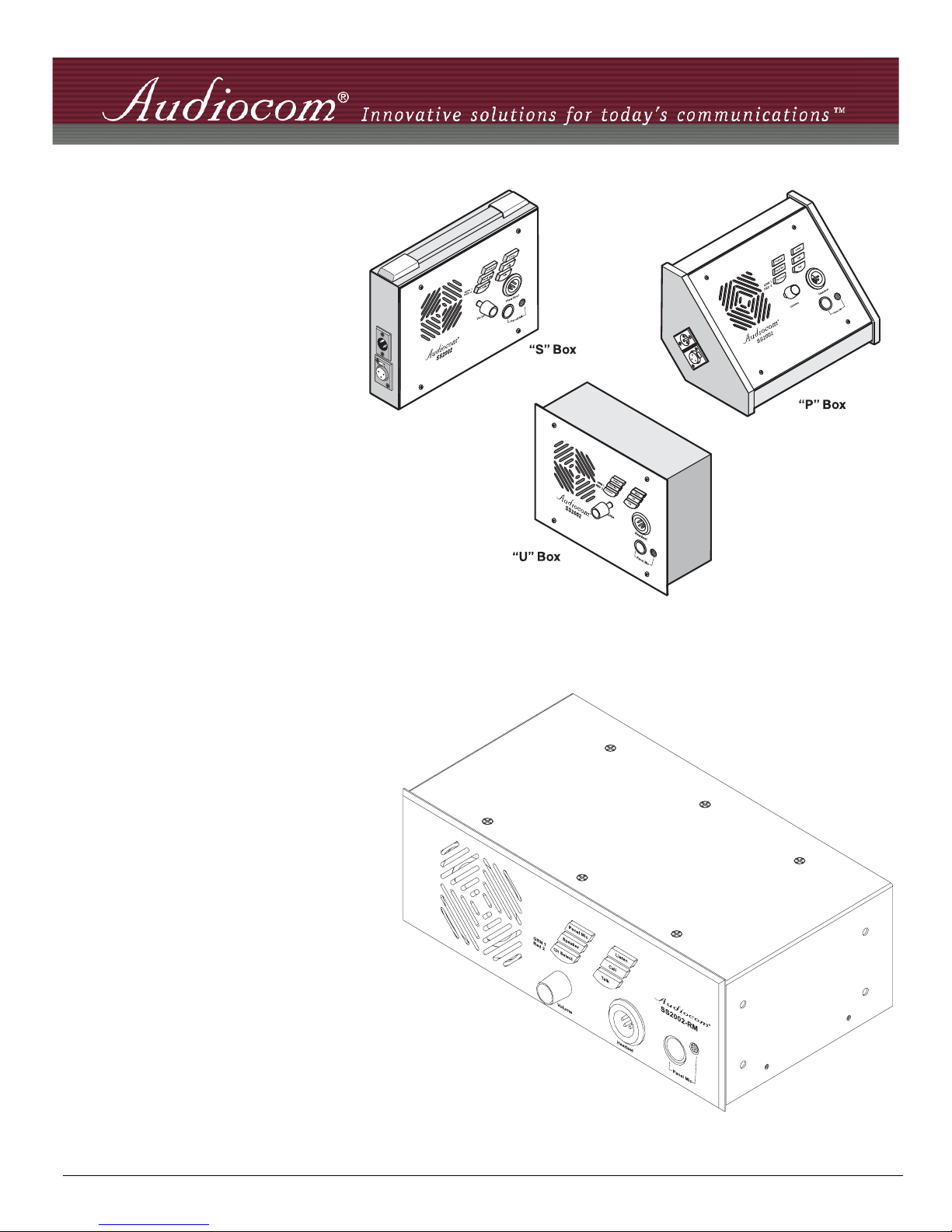
Model SS-1002
Single Channel
Intercom Speaker
Station
Models SS-2002
Two Channel
Intercom Speaker
Station
Model SS-2002 RM
Two Channel Rack
Mount Intercom
Speaker
Station
9350-7741-000 Rev B 05/2006

PROPRIETARY NOTICE
The product information and design disclosed herein were originated by
and are the property of Telex Communications, Inc. Telex reserves all
patent, proprietary design, manufacturing, reproduction, use and sales
rights thereto, and to any article disclosed therein, except to the extent
rights are expressly granted to others.
COPYRIGHT NOTICE
Copyright 2006 by Telex Communications, Inc. All rights reserved.
Reproduction, in whole or in part, without prior written permission from
Telex is prohibited.
WARRANTY NOTICE
See the enclosed warranty card for further details.
CUSTOMER SUPPORT
Technical questions should be directed to:
Customer Service Department
RTS/Telex Communications, Inc.
12000 Portland Avenue South
Burnsville, MN 55337 USA
Telephone: 800-392-3497
Fax: 800-323-0498
Factory Service: 800-553-5992
RETURN SHIPPING INSTRUCTIONS
Customer Service Department
Telex Communications, Inc. (Lincoln, NE)
Telephone: 402-467-5321
Fax: 402-467-3279
Factory Service: 800-553-5992
Please include a note in the box which supplies the company name,
address, phone number, a person to contact regarding the repair, the type
and quantity of equipment, a description of the problem and the serial
number(s).
FCC Statement
This equipment uses, and can radiate radio frequency energy that
may cause interference to radio communications if not installed
in accordance with this manual. The equipment has been tested
found to comply with the limits of a Class A computing device
pursuant to Subpart J Part 15 of FCC Rules which are designed to
provide reasonable protection against such interference when
operated in a commercial environment. Operation of this
equipment in a residential area may cause interference which the
user (at his own expense) will be required to correct.
This product meets Electromagnetic Compatibility
Directive 89/336/EEC
Shipping to the Manufacturer
All shipments of product should be made via UPS Ground, prepaid (you
may request from Factory Service a different shipment method). Any
shipment upgrades will be paid by the customer. The equipment should
be shipped in the original packing carton. If the original carton is not
available, use any suitable container that is rigid and of adequate size. If
a substitute container is used, the equipment should be wrapped in paper
and surrounded with at least four (4) inches of excelsior or similar
shock-absorbing material. All shipments must be sent to the following
address and must include the Proof of Purchase for warranty repair.
Upon completion of any repair the equipment will be returned via
United Parcel Service or specified shipper, collect.
Factory Service Department
Telex Communications, Inc.
8601 East Cornhusker Hwy.
Lincoln, NE 68507 U.S.A.
Attn: Service
This package should include the following:
QTY DESCRIPTION PART NO.
1 SS-1002, 1 channel front plate
assembly
9010-7741-000
1 SS-2002, 2 channel front plate assem-
bly
9010-7741-001
1 User Manual 9350-7741-000
4 Screw, Flat Hd, 6-32 x 5/16” 51847-122
One of the following, depending on what was ordered:
1 P-box, 1-channel 9010-7627-007
1 S-box, w/handle, 1-channel 9010-7627-008
1 P-box, 2-channel 9010-7627-009
1 S-box, w/handle, 2-channel 9010-7627-010
1 U-box 9010-7627-004
1 S-box, w/out handle, 1-channel 9010-7627-011
1 S-box, w/out handle, 2-channel 9010-7627-012
1 Warranty Card 38110-390
2 End Caps 9310-7620-001
1 Statement of Conformity 38109-675
SS-2002RM
1 SS-2002RM Final Assembly 9010-7742-000
4 Foot, bumper, black 56471-001
1 User Instructions 9350-7741-000
1 Statement of Conformity 38109-675
1 Warranty 38110-390

TABL
E
OF
CONTENTS
Chapter 1 Introduction
Introduction ................................................................................................................................................. 3
Description .................................................................................................................................................. 3
Features ....................................................................................................................................................... 3
Chapter 2 Installation
Configuration Pre-check ............................................................................................................................. 7
DIP Switches ............................................................................................................................................... 7
Mic Kill Receive ......................................................................................................................................... 7
Call Signal Compatibility ........................................................................................................................... 8
Incoming Call Beep .................................................................................................................................... 8
Microphone Type ........................................................................................................................................ 8
Speaker Beep for Incoming Call ................................................................................................................. 8
Balanced / Unbalanced Switch ................................................................................................................... 8
Sidetone Trimmers ...................................................................................................................................... 9
Headset Connector Notes ............................................................................................................................ 9
Panel Mic Connector Notes ........................................................................................................................9
Intercom Channel Connections ................................................................................................................... 9
Description of Phantom-Powered Connection ......................................................................................... 10
Description of Locally Powered Connection ............................................................................................ 10
All Locally Powered Intercom Stations (Dry Lines) ................................................................................12
Chapter 3 Operation and Specifications
Power Up .................................................................................................................................................. 15
Sidetone Adjustment ................................................................................................................................. 15
Channel Select (SS-2002 & SS-2002RM Only) ....................................................................................... 16
Headset/Headphone/Speaker/Microphone Selection ................................................................................ 16
Receiving Calls ......................................................................................................................................... 16
Calling an Intercom Channel ....................................................................................................................16
Specifications ............................................................................................................................................ 17
Dimensions ............................................................................................................................................... 18
Notes ......................................................................................................................................................... 19


3
CHAPTER 1
Introduction
Introduction
Thank you for purchasing the Audiocom SS-1002/2002/2002RM Intercom Speaker Station. We hope the many design features
of this product will satisfy your intercommunication requirements for many years to come. To get the most out of you new
intercom stations, please take a few moments to look through this booklet before using the Intercom Speaker Stations for the
first time.
Description
The Intercom Speaker Stations may be used with a headset, or with the built-in speaker and the panel microphone or an
optional gooseneck microphone. Another alternative is to use headphones and either the built-in panel microphone or an
optional gooseneck microphone. As an alternative to a headset, a telephone style handset may also be used. The SS-1002 is a
single-channel station; the SS-2002 & SS-2002RM provide switch selectable access to either of two intercom channels. Both
the SS-1002 and the SS-2002 com in three version to suit a variety of applications. The “S” box is a portable version. It has a
carrying handle and dual “loop-through” intercom connectors which permit stations to be quickly interconnected using prefabricated cables. The “P” box is stationary version. It also has dual “loop-through” connectors for quick interconnection, but
the case is designed for desktop or console-mount applications. The “U” box is designed for permanent, in-the-wall mounting.
It uses push type wire terminals for connection to the intercom system. In addition, the SS-2002RM can be used on a desktop
or mounted in a standard 19” equipment rack (using the optional RM-14 Rack Mount Kit).
Features
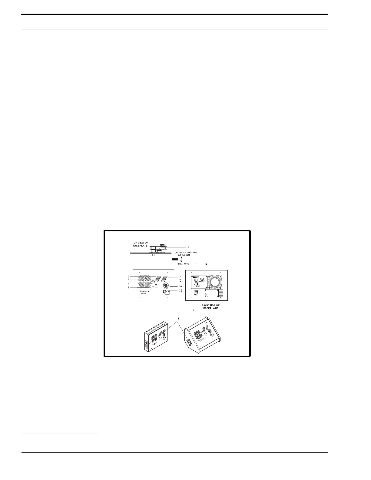
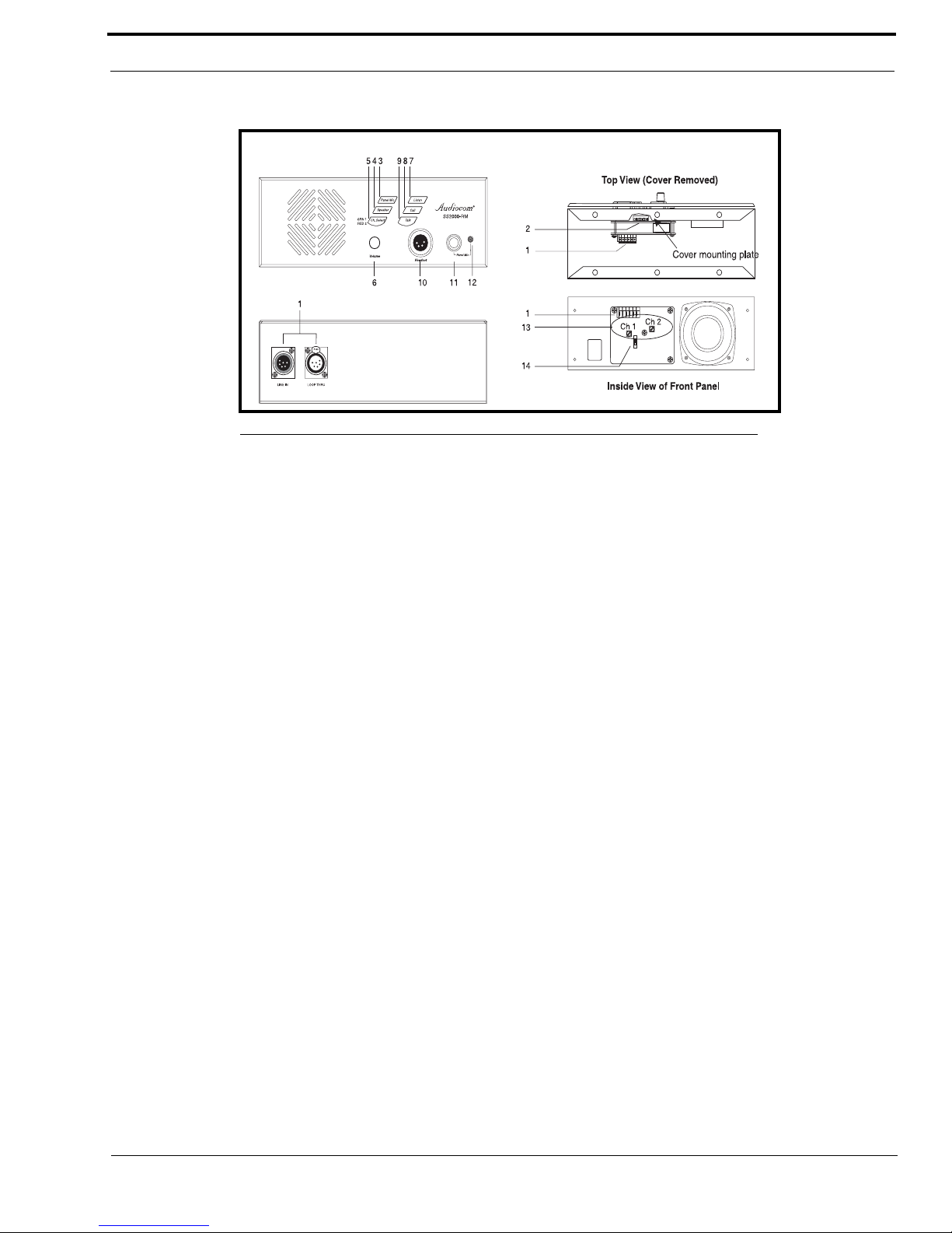
1. Channel and Power Connections - The “U” box uses quick release terminals to connect to audio and power wires. For the
“S” box and “P” box versions, the terminal connections are brought out to the dual, loop-thru XLR connectors on the side
of the box. These permit several stations to be connected in a string, or daisy-chain, using pre-fabricated intercom cables.
2. Configuration DIP Switches - These switches control the following features:
Call Beep: In addition to a flashing call key indication for incoming calls, an incoming call beep tone can also be
used.
Headset Microphone Type Selection: Either a balanced or unbalanced dynamic microphone can be selected.
DC call enable: This may be turned on to use the intercom station with intercom systems that use DC call signaling.
Introduction
4
3. Panel Mic Key - Selects the Panel Mic connector / Built-in Mic (11) in the ON position and the headset connector (10) in
the OFF position.
4. Speaker Key - Selects the built-in speaker in the ON position and the Headset connector (10) in the OFF position.
5. Channel Select Key (SS-2002 & SS-2002RM only) - Selects intercom channel 1 or 2. The key lights green for channel 1 and
red for channel 2.
6. Volume Control - Adjusts intercom listen volume to headphones or speaker.
7. Intercom Listen Key - Both momentary (push-to-listen) and latching (hands-free-listen) are possible.
8. Call Key - Used to send call signals on the intercom channel. Flashes for incoming calls.
9. Intercom Talk Key - Both momentary (push-to-talk) and latching (hands-free-talk) are possible. All models are also
equipped with a “mic kill receive” circuit, which allows an operator at a remote master station (such as the US-2000A) to
turn OFF the talk key on all stations on the intercom line.
10. Dynamic-Mic Headset Connector - 4-pin male XLR connector accepts headsets with monaural headphones and either a
balanced or unbalanced dynamic microphone. Also accepts a telephone style handset. Can also be used with headphones
when a Panel Mic is connected. Can also be used with a handheld microphone along with the internal speaker.
11. Panel Mic Connector - Accepts an electret gooseneck microphone such as the Telex MCP-90.
12. Built-in Panel Microphone - Active when the Panel Mic key is pressed and a gooseneck microphone is not inserted in the
Panel Mic connector.
13. Sidetone Trimmers - These adjust the level of the user’s own voice in the headphones when using full-cushion headphones.
(Eliminates the muffled sensation when talking with the ears completely covered.) When using the speaker or open-ear
style headphones, the sidetone trimmers are adjusted to eliminate the user’s voice from the headphones or speaker. This
helps to prevent feedback.
14. Balanced / Unbalanced Selector Switch - This switch sets the intercom station for compatibility with either Audiocom
(balanced) or Clear-Com
1
(unbalanced) intercom systems.
FIGURE 1. SS-1002/2002 Features
1. Brand Names mentioned are the property of their respective companies.
5
Features
FIGURE 2. SS-2002RM Features
 Loading...