

Page 1
Model PS-2001L
Power Supply
Model SPS-2001 Power Supply
-2001L
S
P
1
2
™
SPS-2001
1
2
™
Volume
9350-7699-000 Rev D 12/2006
Page 2

PROPRIETARY NOTICE
SHIPPING TO THE MANUFACTURER
The product information and design disclosed herein were originated by
and are the property of Telex Communications, Inc. Telex reserves all
patent, proprietary design, manufacturing, reproduction, use and sales
rights thereto, and to any article disclosed therein, except to the extent
rights are expressly granted to others.
COPYRIGHT NOTICE
Copyright 2006 by Telex Communications, Inc. All rights reserved.
Reproduction, in whole or in part, without prior written permission from
Telex is prohibited.
WARRANTY NOTICE
See the enclosed warranty card for further details.
CUSTOMER SUPPORT
Technical questions should be directed to:
Customer Service Department
RTS/Telex Communications, Inc.
12000 Portland Avenue South
Burnsville, MN 55337 USA
Telephone: 800-392-3497
Fax: 800-323-0498
Factory Service: 800-553-5992
RETURN SHIPPING INSTRUCTIONS
Customer Service Department
Telex Communications, Inc. (Lincoln, NE)
Telephone: 402-467-5321
Fax: 402-467-3279
Factory Service: 800-553-5992
Please include a note in the box which supplies the company name,
address, phone number, a person to contact regarding the repair, the type
and quantity of equipment, a description of the problem and the serial
number(s).
All shipments of product should be made via UPS Ground, prepaid (you
may request from Factory Service a different shipment method). Any
shipment upgrades will be paid by the customer. The equipment should
be shipped in the original packing carton. If the original carton is not
available, use any suitable container that is rigid and of adequate size. If
a substitute container is used, the equipment should be wrapped in paper
and surrounded with at least four (4) inches of excelsior or similar shockabsorbing material. All shipments must be sent to the following address
and must include the Proof of Purchase for warranty repair. Upon completion of any repair the equipment will be returned via United Parcel
Service or specified shipper, collect.
Factory Service Department
Telex Communications, Inc.
8601 East Cornhusker Hwy.
Lincoln, NE 68507 U.S.A.
Attn: Service
This package should include the following:
PS-2001L
Qty. Description Part No.
1 PS-20001L Final Assembly 9010-7699-001
1 User Manual 9350-7699-000
1 Warranty Statement 38110-390
4 Rubber Feet 56471-001
1 Power Cord, Black 2504-0003-00
1 Statement of Conformity 38109-675
SPS-2001
1 PS-20001L Final Assembly 9010-7699-001
1 User Manual 9350-7699-000
1 Warranty Statement 38110-390
4 Rubber Feet 56471-001
1 Power Cord, Black 2504-0003-00
1 Patch Cord 50628-003
1 Statement of Conformity 38109-675
FCC STATEMENT
This equipment uses, and can radiate radio frequency energy that may cause interference to radio communications if not
installed in accordance with this manual. The equipment has been tested and found to comply with the limits of a Class
A computing device pursuant to Subpart J, Part 15 of FCC Rules which are designed to provide reasonable protection
against such interference when operated in a commercial environment. Operation of this equipment in a residential area
may cause interference which the user (at his own expense) will be required to correct.
This product meets Electromagnetic Compatibility Directive 89/336/EEC.
Page 3

TABLE
CONTENTS
Introduction 3
Description 3
Installation 7
Configuration Switches 7
Intercom Channel and Program Connections 7
Channel Capacity: 7
Audiocom Connections: 7
Clear-Com Applications: 7
Desktop or Rackmount Installation 7
Power-Up Check 13
Specifications 13
OF
Page 4

Page 5
CHAPTER 1
Introduction
Description
The PS-2001L and SPS-2001 are versatile power supplies that can be used in a variety of Audiocom® intercom system
applications. They both directly accept any AC input power from 100 to 240 VAC, 50/60 Hz and can be configured to power
two separate intercom channels or one large intercom channel with twice the intercom station capacity. Additionally, the units
can be configured for compatibility with Clear-Com
For rack mounting, optional hardware is required. For desktop use, four non-marring rubber feet are supplied. The SPS-2001
also provides a speaker with two mixed inputs making it ideal for situations calling for a master station with a microphone/
speaker combination.
®
Intercom Systems. The units may be rack mounted or used on a desktop.
®
3
100-240 VAC 60/50 HZ
TELEX COMMUNICATIONS, INC. MADE IN USA
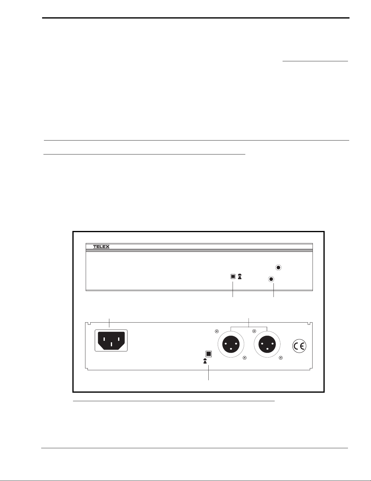
FIGURE 1. PS-2001L Front and Rear Panel Features
UNBAL
BAL
5
Combine
Isolate
1
4
CH 1
CLASS 2 WIRING 1.5A 24VDC
PS-2001L
1
2
2
CH 2
3
Page 6

Introduction
1. Combine/Isolate Switch: When in the Combine position, the unit will combine the audio signals of the two channels to
create a single audio channel where all users can intercommunicate. When in the Isolate position, the unit will create two
groups of completely independent users.
2. Channel Status Indicators: The indicators are green for normal operation and red when there is an overload or short circuit.
The circuitry in the unit will automatically reset when the overload or short circuit is located and fixed.
3. Universal AC Power Input: The unit accepts any input power in the range of 100-240 VAC, 50/60 Hz.
4. Intercom Channel Connectors: When the Combine/Isolate switch is set to the Isolate position, each channel connector is
powered separately and has completely separate intercom audio. When the Combine/Isolate switch is set to the Combine
position, each channel is still powered separately, but the audio signals are combined so that all users on both channels can
intercommunicate.
5. BAL/UNBAL Selector Switch: This selector switch allows the user to configure the unit for use in either an Audicom
®
(BALANCED) or Clear-Com (UNBALANCED) system. Compatibility includes channel connector pin-outs, channel
®
power requirements, and call signaling requirements. The default setting for this switch is in the Audiocom
(BAL)
position.
®
12
4
SPEAKERS
LINE LEVEL
100-240 VAC 60/50 HZ
TELEX COMMUNICATIONS, INC. MADE IN USA
FIGURE 2. SPS-2001 Front and Rear Panel Features
1VRMS
INPUT 1
INPUT 2
Volume
UNBAL
BAL
6
Combine
Isolate
5
CH 1
CLASS 2 WIRING 1.5A 24VDC
SPS-2001
1
2
3
CH 2
1. Speaker, Inputs, and Volume Control: Two audio inputs are provided. The inputs are combined internally and set as a
monaural signal to the internal speaker amplifier. The Volume control adjusts the level to the front panel speaker. Typically,
these inputs are used with the speaker outputs of a master station when the master station is set for use with a panel
microphone and speaker instead of a headset.
2. Combine/Isolate Switch: When in the Combine position, the unit will combine the audio signals of the two channels to
create a single audio channel where all users can intercommunicate. When in the Isolate position, the unit will create two
groups of completely independent users.
3. Channel Status Indicators: The indicators are green for normal operation and red when there is an overload or short circuit.
The circuitry in the unit will automatically reset when the overload or short circuit is located and fixed.
4. Universal AC Power Input: The unit accepts any input power in the range of 100-240 VAC, 50/60 Hz.
4
Page 7

Description
5. Intercom Channel Connectors: When the Combine/Isolate switch is set to the Isolate position, each channel connector is
powered separately and has completely separate intercom audio. When the Combine/Isolate switch is set to the combine
position, each channel is still powered separately, but the audio signals are combined so that all users on both channels can
intercommunicate.
6. BAL/UNBAL Selector Switch: This selector switch allows the user to configure the unit for use in either an Audiocom
(BALANCED) or Clear-Com (UNBALANCED) system. Compatibility includes channel connector pin-outs, channel
power requirements, and call signaling requirements. The default setting for this switch is in the Audiocom
®
(BAL)
position.
®
5
Page 8

Introduction
6
Page 9

CHAPTER 2
Installation
Configuration Switches
The BAL/UNBAL switch (located on the rear of the unit) is set to the Balanced (Audiocom) position when the unit is shipped
from the factory. To set the switch to the Unbalanced (Clear-Com) mode, use a pointed object such as a pen to push in the
switch.
The Combine/Isolate switch (located on the front of the unit) can be changed at any time by using a pointed object such as pen
to push in the switch. When the switch is in the Combine position, all users on both channels may intercommunicate. When the
switch is set to the Isolate position, channels 1 and 2 cannot intercommunicate.
Intercom Channel and Program Connections
Channel Capacity:
When connecting intercom stations to the PS-2001L or SPS-2001, determine the total current for all stations on each channel.
The total per channel should no exceed 2A. If you exceed this limit, an overload indication will be provided and the output of
the power supply will be turned OFF. Once the overload is corrected, the overload indications will disappear and the power
supply output will be turned ON. Note, if you are using DC wallpacks with some intercom stations, you do not need to add the
current consumption of those station to the total current.
Audiocom Connections:
Intercom cable wiring details are shown in figure X. Speaker and interconnection cables (SPS-2001 Only) are standard RCA
phono types. For program input cable wiring, refer to your master intercom station user manual. Some typical applications are
shown in the figures on page 9.
Clear-Com Applications:
Refer to your Clear-Com system documentation for intercom cable wiring and connection details.
Desktop or Rackmount Installation
For desktop use, install the four supplied rubber feet to the bottom of the unit. Do not obstruct the cooling vents when using the
unit on a desktop.
7
Page 10

Installation
*
For rack mounting, use an optional Audiocom Rackmount Kit. Several kits are available to meet the requirements of your
particular system. Follow the assembly instructions supplied with the rack mount kit.
TYPICAL 1-CHANNEL CABLE WIRING
33
22
1
Shield Shield
Cable Type: 22AWG Stranded, 2-Pair Twisted-wire, with Shield
Connector Type: 3-Pin XLR Audio (Neutrik or Switchcraft)
Pin 1: Common
Channel Audio / Power
Pin 2:
Pin 3: Channel Audio / Power
Shield
: Earth ground
44
33
66
55
1
Shield Shield
Cable Type: 22AWG Stranded, 3-Pair Twisted-wire, with Shield
Connector Type: 6-Pin XLR Audio (Neutrik only, not compatible with 6-pin Switchcraft)
Pin 1: Channel 1 & 2 Common
Pin 2: No connection
Pin 3: Channel 1 Audio / Power
Pin 4: Channel 1 Audio / Power
Pin 5: Channel 2 Audio / Power
Pin 6: Channel 2 Audio / Power
: Earth ground
Shield
3
2
Ch1
1
Case
3
2
Ch2
1
Shield
Pair 1
Pair 2
1 (Both wires)
*
Denotes twisted pair.
Denotes shield.
TYPICAL 2-CHANNEL CABLE WIRING
Pair 1
Pair 2
Pair 3
Denotes twisted pair.
Denotes shield.
“Y” CABLE WIRING
Pair 1
Pair 2
Pair 3
1 (Both wires)
4
3
6
5
1 (Both wires)
Shield
Use second drain wire if available, or add an extra section of wire.
* Standard cables are generally constructed using a male connector at one end and a
female connector at the other end. This allows several cables to be interconnected to
create longer cable runs.
also typically provide both a male and female Neutrik connector for each intercom
channel. This permits loop-through connection of several intercom stations using the
standard cables.
each channel. Audiocom wallplates use male Neutrik connectors.
FIGURE 3. Cable Wiring Diagrams for Audiocom Applications
Audiocom power supplies use a 3-pin male Neutrik connector for
Audiocom master stations, speaker stations and belt packs
8
Page 11

Desktop or Rackmount Installation
PS-2001L
Power Supply
Combine / Isolate Switch
set to Isolate
CH 1
100-240VAC 60/50 HZ
TELEX COMMUNICATIONS, INC. MADE IN USA
BAL
UNBAL
CLASS 2WIRING 1.5A 24VDC
1
PROGRAM
INPUTS
+
12-15VDC
1
SPEAKERS
LINE LEVEL
-
1VRMS
2
EXP
P.A.
BAL - OUT
OUT
UNBAL - IN
PUSH PUSH
VOL
VOL
PGM 2
PGM 1
CHN 1
To all stations
on channel 1
BP-1000
HEADSET LINES
BP-1000 BP-1000
HEADSET LINES HEADSET LINES
1
BP-1000
1 1-channel cable
2 2-channel cable
Y “Y” cable
CH 2
1
US2000A
Master Station
CHN 2
To all stations
on channel 2
11
HEADSET LINES
1
Y
BP-2000
BP-2000
HEADSET LINES
2
HEADSET LINES
Note: A JB-2 Junction Box may be
used instead of the “Y” cables. The
JB-2 provides a means of combining
two channels, while also allowing the
single channels to be continued
directly from the junction box.
Y
BP-1000 BP-1000
HEADSET LINESHEADSET LINES
FIGURE 4. Typical connections using a single PS-2001L Power Supply to power two channels.
9
Page 12

Installation
SPS-2001
Power Supply
Combine / Isolate Switch
set to Isolate
100-240VAC 60/50 HZ
TELEX COMMUNICATIONS, INC. MADE IN USA
Speaker Interconnect cable.
PROGRAM
Program Input
cable. From 2
audio sources
INPUTS
+
12-15VDC
1
SPEAKERS
LINE LEVEL
-
1VRMS
2
EXP
P.A.
OUT
To all stations
BAL - OUT
UNBAL - IN
on channel 1
BP-1000
HEADSET LINES
BP-1000 BP-1000
HEADSET LINES HEADSET LINES
1
CH 1
SPEAKER
INPUT 1
INPUT 2
BAL
LINE LEVEL
UNBAL
1VRMS
1
PUSH PUSH
VOL
PGM 2
PGM 1
CHN 1
CH 2
CLASS 2WIRING 1.5A 24VDC
1
VOL
CHN 2
To all stations
on channel 2
BP-1000
HEADSET LINES
1 1-channel cable
2 2-channel cable
Y “Y” cable
US2000A
Master Station
11
1
Y
BP-2000
BP-2000
HEADSET LINES
2
HEADSET LINES
Note: A JB-2 Junction Box may be
used instead of the “Y” cables. The
JB-2 provides a means of combining
two channels, while also allowing the
single channels to be continued
directly from the junction box.
Y
BP-1000 BP-1000
HEADSET LINESHEADSET LINES
FIGURE 5. Typical connections using on SPS-2001 Power Supply for two intercom channels. The
two program sources are monitored independently by their intercom channels. All audio (program
and intercom) is monitored as a monaural mix in the SPS-2001 speaker. The US2000A is set for
monaural speaker output (default).
10
Page 13

Desktop or Rackmount Installation
SPS-2001
SPK1000
Powered Speaker
TELEX COMMUNICATIONS, INC.
MADE IN USA
+
-
12-15VDC
INPUT 1
INPUT 2
BAL
LINE LEVEL
1VRMS
100-240VAC 60/50 HZ
TELEX COMMUNICATIONS, INC. MADE IN USA
Power Supply
Combine / Isolate Switch
set to Isolate
Speaker interconnect cables.
PROGRAM
Program input
cable. From 2
audio sources
INPUTS
+
12-15VDC
1
SPEAKERS
LINE LEVEL
-
1VRMS
2
EXP
P.A.
OUT
To all stations
BAL - OUT
UNBAL - IN
on channel 1
BP-1000
HEADSET LINES
BP-1000 BP-1000
HEADSET LINES HEADSET LINES
1
CH 1
SPEAKER
INPUT 1
INPUT 2
BAL
LINE LEVEL
UNBAL
1VRMS
1
PUSH PUSH
VOL
PGM 2
PGM 1
CHN 1
CH 2
CLASS 2WIRING 1.5A 24VDC
1
VOL
CHN 2
To all stations
on channel 2
BP-1000
HEADSET LINES
1 1-channel cable
2 2-channel cable
Y “Y” cable
US2000A
Master Station
11
1
Y
BP-2000
BP-2000
HEADSET LINES
2
HEADSET LINES
Note: A JB-2 Junction Box may be
used instead of the “Y” cables. The
JB-2 provides a means of combining
two channels, while also allowing the
single channels to be continued
directly from the junction box.
Y
BP-1000 BP-1000
HEADSET LINESHEADSET LINES
FIGURE 6. Adding an SPK-1000 to the example in Figure X. The two program sources are monitored
independently by the intercom channels. The SPS-2001 monitors intercom channel 1 and program 1.
The SPK-1000 monitors intercom channel 2 and program 2. The US2000A is sent for binaural speaker
output as described in the US2000A User Manual.
11
Page 14

Installation
PS-2001L
Channel 1 Power
Combine / Isolate Switch
set to Combine
100-240VAC 60/50 HZ
TELEX COMMUNICATIONS, INC. MADE IN USA
BAL
UNBAL
CH 1
CLASS 2WIRING 1.5A 24VDC
CH 2
100-240VAC 60/50 HZ
TELEX COMMUNICATIONS, INC. MADE IN USA
PS-2001L
Channel 2 Power
Combine / Isolate Switch
set to Combine
CH 2
CH 1
BAL
UNBAL
CLASS 2WIRING 1.5A 24VDC
1
1
BAL - OUT
UNBAL - IN
PUSH PUSH
VOL
VOL
PGM 2
PGM 1
CHN 1
CHN 2
PROGRAM
INPUTS
1
SPEAKERS
LINE LEVEL
+
-
1VRMS
2
EXP
P.A.
OUT
12-15VDC
PS-L
(Optional)
1
To ½ of stations
on channel 1
1 1 1
To ½ of stations
on channel 1
To ½ of stations
on channel 2
To ½ of stations
on channel 2
FIGURE 7. Using two PS-2001L Power Supplies to provide a greater capacity on each channel.
SPS-2001
Channel 1 Power
Combine / Isolate Switch
set to Combine
SPEAKER
INPUT 1
100-240VAC 60/50 HZ
TELEX COMMUNICATIONS, INC. MADE IN USA
INPUT 2
BAL
LINE LEVEL
UNBAL
1VRMS
CH 1
CLASS 2WIRING 1.5A 24VDC
CH 2
100-240VAC 60/50 HZ
TELEX COMMUNICATIONS, INC. MADE IN USA
SPS-2001
Channel 2 Power
Combine / Isolate Switch
set to Combine
CH 2
CH 1
SPEAKER
INPUT 1
INPUT 2
BAL
LINE LEVEL
UNBAL
1VRMS
CLASS 2WIRING 1.5A 24VDC
1
44
1
BAL - OUT
UNBAL - IN
PUSH PUSH
VOL
VOL
PGM 2
PGM 1
CHN 1
CHN 2
PROGRAM
INPUTS
1
SPEAKERS
LINE LEVEL
+
-
1VRMS
2
EXP
P.A.
OUT
12-15VDC
US2000A
Internal DIP
PS-L
(Optional)
switches set
for binaural
operation
Program input
cable. From 2
1
audio sources
To ½ of stations
on channel 1
1 1 1
To ½ of stations
on channel 1
To ½ of stations
on channel 2
To ½ of stations
on channel 2
FIGURE 8. Using two SPS-2001 Power Supplies to provide a greater capacity on each channel.
Using two SPS-2001 Power Supplies also lets you independently monitor and adjust volume for
both intercom channels without the need for a separate powered loudspeaker. In this application,
the US-2000A should be set for binaural speaker output as described in the US2000A manual.
12
Page 15

Power-Up Check
Power-Up Check
1. Plug in any DC wallpacks that are being using with indi-
vidual intercom stations.
NOTE: If you plug in DC wallpacks after applying power to
the PS2001L or SPS-2001, you may get an overload
indication. This is because the stations that are being
powered by wallpacks will draw current from the units until
their own DC wallpack supplies are connected. To correct
the problem, plug in the DC wallpacks.
2. Plug in the AC power cords for any connected PS-2001L
or SPS-2001 Power Supplies. The channel status
indicators should be green.
3. If a channel status indicator turns red during operation,
locate the short or overload that is causing the problem.
Once the short or overload is corrected, the Power Supply
should reset itself and the overload indication should go
away.
Specifications
Unbalanced Mode (set to UNBAL position)
Line Terminating Impedance: 150 ohms ±5%
Connector Pin-out:
Pin 1 Common (audio and DC return)
Pin 2 +24 VDC output
Pin 3 Full-duplex, unbalanced intercom audio high
Speaker Inputs (SPS-2001 only)
Type:
RCA Phone Jack
Tip: Speaker + Input
Sleeve: Speaker - Input
Approvals
UL, CUL, CE
General
Input Power Requirements
100 to 240 VAC, 50/60 Hz
Output Power (each channel)
21 ±1 VDC, 1 Amp per channel
Dimensions
1.75” (44.5 mm) high x 8.25” (209.5mm) wide x 10.31” (261.9mm) deep
Wei ght
approximately 2.5 lb. (1.13 kg.)
Environmental Requirements
Storage:
-20° C to 80° C, 0% to 95% humidity, non-condensing
Operating:
0° C to 50° C, 0% to 95% humidity, non-condensing
Intercom Channels (General)
Connector Type:
One XLR-3M audio connector for each channel. Pin-out depends on setting
of BAL/UNBAL switch for balanced or unbalanced operation as defined
below:
Balanced Mode (set to BAL position)
Line Terminating Impedance: 300 ohms ±10%
Connector Pinout
Pin 1 Common (audio and DC return)
Pin 2 Full-duplex, balanced intercom audio and +24 VDC output
Pin 3 Full-duplex, balanced intercom audio and +24 VDC output
13
Page 16

 Loading...