

Page 1
Operating Instructions
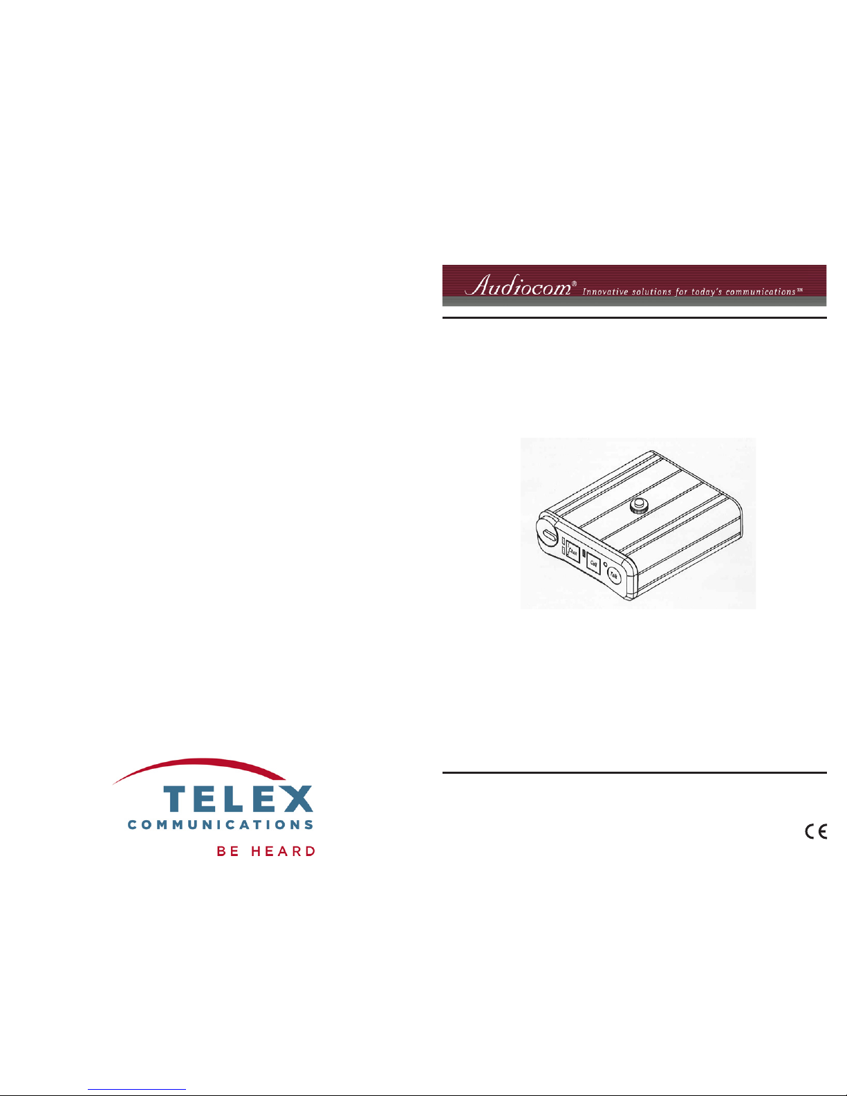
NFL-2002 Beltpacks
9350-7775-000 Rev C 5/2006
Page 2
FCC STATEMENT
This equipment uses, and can radiate radio
frequency energy that may cause interference
to radio communications if not installed in
accordance with this manual. The equipment
has been tested and found to comply with the
limits of a Class A computing device pursuant
to Subpart B, Part 15 of FCC Rules which are
designed to provide reasonable protection
against such interference when operated in a
commercial environment. Operation of this
equipment in a residential area may cause
interference which the user (at his own
expense) will be required to correct.
Audiocom® is a registered trademark of
Telex Communications, Inc., Burnsville,
Minnesota 55337
Clear-Com® is a registered trademark of
Clear-Com Intercom Systems
2 11
Proprietary Notice
The product information and design disclosed
herein were orignated by and are the property
of Telex Communications, Inc. Telex reserves all
patent, proprietary design, manufacturing,
reproduction, use and sales rights thereto, and
to any article disclosed therein, except to the
extent rights are expressly granted to others.
Copyright Notice
Copyright 2006 by Telex Communications, Inc.
All rights reserved. Reproduction, in whole or in
part, without prior written permission from Telex
is prohibited.
Warranty Notice
See enclosed warranty card for further details.
Customer Support
Technical questions should be directed to:
Customer Service Department
RTS/Telex Communications, Inc.
12000 Portland Avenue South
Burnsville, MN 55337 USA
Telephone: 800-392-3497
Fax: 800-323-0498
Factory Service: 800-553-5992
Return Shipping Instructions
Customer Service Department
Telex Communications, Inc. (Lincoln, NE)
Telephone: 402-467-5321
Fax: 402-467-3279
Factory Service: 800-553-5992
Please include a note in the box which supplies
the company name, address, phone number, a
person to contact regarding the repair, the type
and qunatity of equipment, a description of the
problem and the serial number (s).
Shipping to the Manufacturer
All shipments of product should be made via
UPS Ground, prepaid (you may request from
Factory Service a different shipment method).
Any shipment upgrades will be paid by the
customer. The equipment should be shipped in
the original packing carton. If the original carton
is not available, use any suitable container that
is rigid and of adequate size. If a substitute
container is used, the equipment should be
wrapped in paper and surrounded with at least
four (4) inches of excelsior or similar shockabsorbing material. All shipments must be sent
to the following address and must include the
Proof of Purchase for warranty repair. Upon
completion of any repair, the equipment will
be returned via United Parcel Service or
specified shipper, collect.
Factory Service Department
Telex Communications, Inc.
8601 Cornhusker Hwy.
Lincoln, NE 68507 U.S.A.
Attn: Service
This package should include the following:
YTQnoitpircseD.oNtraP
1ylbmessAlaniF2002-LFN000-0177-0109
1launaMnoitarepO000-5777-0539
1draCytnarraW093-01183
1dr
oCkcaptleBLFN000-7880055
hctiwS/repmuJ
rebmuN
noitcnuFhctiwSrorepmuJgnitteStluafeD
2PJ&1PJ
ETON 2PJdna1PJ:
ehtniebotdeen
noitisopemas
tceleSrewoP3&2sniP
detrohs
detrohs3&2sniP:rewoPenOlennahC
detrohs2&1sniP:rewoPowTlennahC
1WSmocoiduA/moC-ra
elC
®
noitarepOLAB
eniLdecnalaB/decnalabnU
3PJtluafednotfelebtsuM3&2sniP
detrohs
Table 2. Internal Switches and Jumpers
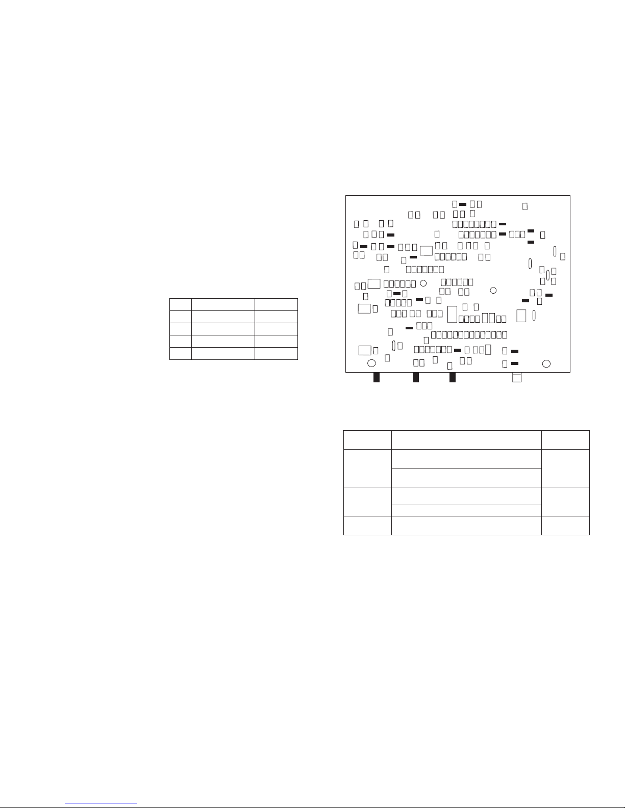
Figure 3. Printed Circuit Board
C61
Sidetone
Mic Gain
Mic Gain
Page 3

10
3
APPENDIX A
OPTIONAL FOOTBALL MODIFICATIONS
GENERAL DESCRIPTION
In Audiocom® Intercom Systems, the Mic-Kill feature is used to turn off any activated
microphones on a selected channel. The Mic-Kill feature is activated when the beltpack
receives a 24 kHz signal from the channel. In some applications the Mic-Kill and Call
signal features are not desired and need to be disabled.
ELIMINATING MIC-KILL AND CALL SIGNAL
CAUTION: TO PREVENT DAMAGE TO THE EQUIPMENT, THESE MODIFICATIONS
SHOULD ONLY BE MADE BY QUALIFIED TECHNICIANS.
If desired, the Mic-Kill and Call signal features can be disabled in the NFL-2002 by
removing a surface-mounted capacitor from the printed circuit board. Perform the
following:
1. Before making changes to the printed circuit board, disconnect all power and line
connections from the beltpack.
2. Refer to Figure 3 and locate C61 on the underside of the printed circuit board.
3. Remove capacitor C61 from the printed circuit board.
RESTORING MIC-KILL AND CALL SIGNAL
To restore the Mic-Kill and Call signal features, replace C61 with Telex® part number
102881-140, 1500 pF, 50V capacitor.
Introduction
The Audiocom
®1
NFL-2002 is a microprocessor controlled two-channel
intercom beltpack. An internal switch and jumper setting allows the unit to be
used with Clear-Com®2 components, if desired. Other internal switch and
jumper settings allow the unit to be uniquely configured to the operator’s
requirements.
OPERATION
SYSTEM POWER
The NFL-2002 beltpack receives power externally in one of two ways:
• The intercom channel
• The local-power (pin 2) of the intercom channel connector
INITIAL NFL-2002 SETUP
The channel termination is initially set for balanced operation, which is
compatible with other Audiocom® equipment. If the unit is going to be
connected to Clear-Com equipment, one switch must be changed as
described on page 11.
The headset is auto-sensing which means the unit automatically determines if
an Electret or Dynamic headset is attached to the unit.
1. Audiocom® is a registered trademark of Telex Communications, Incl., Burnsvilled, MN 55337
2. Clear-Com® is a registered trademark of Clear-Com Intercom Systems.
Page 4
4 9
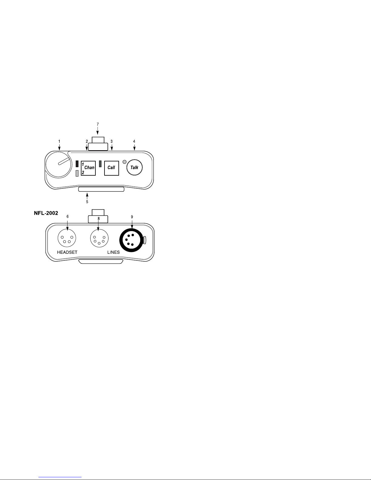
Figure 1. NFL-2002 Connections and Controls
SPECIFICATIONS
GENERAL:
Power Requirements:
Channel supplied: 24 VDC nominal, 40 to 100 mA
Local-power: 24 VDC nominal (21 to 30 VDC), 40 to 100 mA
Environmental Requirements:
Storage: -20ºC to 80ºC; 0% to 95% humidity, non-condensing
Operating: -15ºC to 60ºC; 0% to 95% humidity, non-condensing
Dimensions: 5.0" (127 mm) H x 3.5" (88.9 mm) W x 1.8" (45.7 mm) D
Weight: 1.5 pounds (0.68 kg)
INTERFACE REQUIREMENTS:
Headset:
1000 - 3000 ohm electret microphone
50 - 200 ohm dynamic microphone
150 to 600 ohm headphones
Input Level:
4 mVRMS (nominal)
Balanced Intercom Channel:
Output Level: 1 VRMS nominal
Terminating Impedance: 300 ohm ±5%
Bridging Impedance: greater than 10,000 ohm
Call Signalling:
Send: 20 kHz ±100 Hz, 500 mVRMS ±10%
Receive: 20 kHz ±800 Hz, 100 mVRMS
Mic-Off Frequency:
Detect: 24 kHz ±800 Hz, 100 mVRMS
Noise Contribution: less than -60 dBu on the line
Total Harmonic Distotion: less than 1% at channel output for normal input
Unbalanced Intercom Channel:
Output Level: 775mVRMS ±10%
Terminating Impedance: 200 ohm ±5%
Bridging Impedance: greater than 10,000 ohm
Call Signalling:
Send: 12 ±3 VDC on the line
Receive: 4 - 15 VDC from the line
Total Harmonic Distotion: less than 1% at channel output for normal input
HEADPHONE AMPLIFIER:
Maximum Output:
4.5 ±10% VRMS into 150Ω headset
Frequency Response:
200 Hz to 8 kHz ±2 dB
Audible Alert:
1 kHz, at the headset
Total Har monic Distortion:
Less than 1% at less than 3.5 VRMS into 150Ω headset
Sidetone:
20 ±3 dB minimum range, adjustable
Page 5

58
EXTERNAL CONNECTIONS & CONTROLS
NOTE: The numbers refer to the callouts in Figure 1.
1. VOLUME CONTROL: Use this control to adjust the headset listen level.
2. CHAN BUTTON AND INDICATORS: The Chan button allows the user to select
which intercom channel is active. Press the Chan button to change the
channel selection. The yellow indicator next to the channel number lights
to show the active channel.
3. CALL BUTTON AND INDICATOR: The Call function allows the user to send or
receive signals to other devices on the intercom channel selected. The
Call button operates in two ways:
Call receive
: When there is an incoming call signal, the indicator is
red. (If Audible Call Alert is enabled, incoming calls will cause beeps
in the headset.) On the NFL-2002, calls can be received on the
selected channel only.
Call send
: To send a call signal to all stations on a channel, press and
hold the Call button until a verbal response is received. The indicator
will glow red. On the NFL-2002, calls can be sent on the selected
channel only.
4. TALK BUTTON AND INDICATOR: The Talk button activates the headset
microphone and operates in two ways:
Latched Mode:
Tap the button once to talk. The indicator will glow green. Tap the
button again when finished with a conversation.
Momentary Mode:
Press and hold the button to talk momentarily. Release the button
when finished talking.
NOTE: If no headset is connected when the Talk button is pressed, the
Talk button will have the same function as the Chan button.
5. SIDETONE CONTROL: When using a headset, this control adjusts your own
voice level heard in the headphones. To adjust the level, tap the Talk
button once to turn on the headset microphone. Then, use a small flatblade screwdriver to increase or decrease your voice level while talking
into the microphone. (This control is accessible by removing one screw of
belt clip.)
6. HEADSET CONNECTOR: This connector accepts a four wire Telex® boommicrophone headset.
CONNECTOR PIN CONFIGURATIONS
Headset Connector
Type: XLR-4M (callout 6 in Figure 1)
Pin 1 Headset microphone low
Pin 2 Headset microphone high
Pin 3 Headphone high
Pin 4 Headphone low
Intercom Channel Connectors
NFL-2002
Type: One XLR-5M (callout 8 in Figure 1)
Audiocom® Mode (Internal switch SW1 and set to BAL position)
Pin 1 Common
Pin 2 Local power (21-30 VDC)
Pin 3 Channel A intercom audio low and +24 VDC input
Pin 4 Channel A intercom audio high and +24 VDC input
Pin 5 Channel B intercom audio low and +24 VDC input
Pin 6 Channel B intercom audio high and +24 VDC input
Clear-Com Mode (Internal switch SW1 and jumpers set to UNBAL position)
Pin 1 Common
Pin 2 Local power (21 to 30 VDC)
Pin 3 Channel A +30 VDC input
Pin 4 Channel A intercom audio/call signal
Pin 5 Channel B +30 VDC input
Pin 6 Channel B intercom audio/call signal
Side Tone Adjustment (R145)
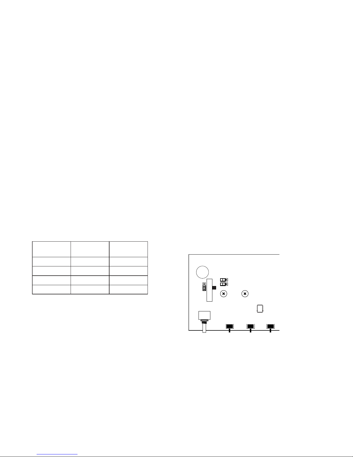
The side tone adjustment is accessible either internally (refer to Figure 2) or by
removing the belt clip mounting screw (callout 5 in Figure 1).
To adjust the level of your own voice heard in the headphones, tap the Talk button once
to turn on the headset microphone. Then, use a small flat-blade screwdriver to increase
or decrease your voice level while talking into the microphone.
Mic Gain Adjustment (R156)
The Mic Gain adjustment is accessible internally on the board (R156), see Figure 2.
To adjust Mic Gain, do the following:
Using a Phillips head screw driver, turn the Mic Gain pot clockwise to increase the gain
(or counter-clockwise to decrease the gain).
Clear-Com Setup
Make the following switch and jumper changes when the beltpack is used with ClearCom equipment:
NFL-2002
1. SW1 must be placed in the UNBAL position.
Page 6
76
7. RADIO PUSH-TO-TALK BUTTON: If the Motorola GP-300 radio is connected to
the beltpack, press the PTT to transmit via the radio. (After pressing PTT,
wait for the tone to stop.)
Note: If the Talk button is in Latched Mode, pressing PTT will
simultaneously transmit your voice via the radio and Intercom system.
8. RADIO CONNECTOR: This connector accepts the five-pin cable supplied to
connect the belt pack to the GP-300 radio.
9. INTERCOM CHANNEL CONNECTORS: Intercom channels are connected via a 6pin connectors (one male and one female).
Local Power Input
Normally the NFL-2002 is powered from the intercom system and will turn
on with the intercom system. The NFL-2002 belt pack may also be
powered from an optional power supply (21-30 VDC; 100 mA) connected
between pin 2 (+) and pin 1 (-) of the intercom channel connector.
Changing Modes of Operation:
Perform the following steps to change the mode of operation.
1. Both the Talk and Call indicators should be OFF and the headset should
be connected.
2. Press and hold the Talk key, then press and hold the Call key, then
release both keys. The Call indicator should now glow red. (The number
of beeps heard in the headset indicates the current mode of operation.)
3. Press the Call key to change to the next mode of operation. Each press
of the Call key will cause the NFL-2002 to change to the next mode of
operation.
4. When the desired mode is reached, press the Talk key to select that mode
and exit the mode changing function. (Beeps will be heard in the headset
when the mode changing function is exited. The number of beeps heard
indicates the selected mode of operation.)
NOTE: Each time the intercom system power is turned on, the beltpack
will reset to the default mode of operation (Mode 2).
M
ODE
(
BEEPS
)
M
ICKILL
A
UDIBLE
C
ALLALERT
1delbasiDdelbasiD
)tluafeD(2delbanEdelbasiD
3delbasiDdelbanE
4delbanEdelbanE
Table 1. Operating Modes
OPERATING MODES
The microprocessor within the NFL-2002 controls four modes of
operation that affect the Microphone Kill and Audible Call Alert features
(as shown in Table 1).
Internal Switches, Jumpers and Adjustments
There are several internal switches, jumpers, and adjustments that affect
operation. These are described below. To gain access to the switches, jumpers
and the adjustments, disconnect all headsets, power and line connections.
Remove two screws from the top of each side and two screws from the bottom
of each side. Switch, jumper and adjustment locations are shown in Figure 2.
Figure 2. Internal Switches, Jumpers and Adjustments
SW1
UBL
BAL
SW5
D
R145
R13
JP3
SW4
D
R156
U7
JP2
JP1
SW3
 Loading...