

Page 1
/
XM READY CD PLAYER WITH FLIP-DOWN
DETACHABLE FACE AND REMOTE
A1100N
OPERATING INSTRUCTIONS
PLEASE RETAIN MANUAL FOR FUTURE USE AND REFERENCE
Page 2

The Audiobahn Way
To bring the product to market that excites the consumer through
sound and vision from an orientation of integrity and customer service. We
make you look as good as you sound. We strive to take car audio to an
extreme the world has never seen, and a world that never stops evolving.
Audiobahn was established in 1997 with one long-term goal in mind,
"Build it Bigger, Badder, & Better, and the people will take notice!" We
back this statement with an engineering team that has brought home several
Innovations, Design & Engineering Showcase Awards, and a marketing team
from around the world that spends countless hours developing our no
compromise products to satisfy the most discriminating enthusiasts.
Our global manufacturing facilities feature IS09002 ratings (the highest
level of quality control awarded in the electronics manufacturing industry), fully
robotic assembly lines and a state of the art, California based R & D
laboratory.
Due to overwhelming response from our competitors, and our goal to
participate in even more events this year, we created *"TEAM AUDIOBAHN."
This organization is designed to create a support network along with shirts and
perks for team members. "TEAM AUDIOBAHN" is not only for the diehard
competitor, but also for anyone that loves car audio as much as we do. With
four levels of play, one is right for you to get started in the Audiobahn family.
Our Technical Department and entire staff look to strive above and
beyond the rest of the pack by going that extra mile to help you out. Whether
you happen to be a veteran competitor, or a beginner car audio enthusiast that
does not know a voice coil from a spider. We are all here to help you get the
best system you can with what you have.
Judge for yourself, and remember what it's all about, "If it's not
Bigger, Badder & Better, it's not Audiobahn." If audio is your life,
Audiobahn is the brand for you! We make you look as good as you sound.
People never stop trying to get the best product, so we will never stop making
it.
*To learn more about "TEAM AUDIOBAHN" please give us a call, see our website at
www.audiobahninc.com, or email us at team@audiobahninc.com to learn about all the details.
Page 3

Introduction
Dear Customer,
Congratulations on your purchase of the world's finest brand of car audio products. Here at
Audiobahn Inc. we are devoted to making our musical reproduction the very best, and we are
pleased you have chosen our product. Through years of engineering expertise, hand
craftsmanship, and critical testing procedures, we have created a wide range of products that
reproduce music with all the clarity and richness you deserve.
For maximum performance we recommend you have your Audiobahn product installed by an
Authorized Audiobahn Dealer, as we provide specialized training through our Audiobahn
Installer Training Programs. Please read your warranty, keep your receipt, and original carton
for possible future use.
Great products and proper installation are only a small piece of the puzzle when it comes to
your system. Make sure that your installer is using only 100% authentic installation accessories
from the Audiobahn Connections. The Audiobahn Connections line has everything ranging
from the smallest terminal, to power wires up to 0 gauge, and 4 channel RCA cables.
To get a free brochure on Audiobahn products and Audiobahn Connections in the U.S. call
(714) 988-0400 or e-mail us at
sales@audiobahninc.com.
WARNING
Continuous exposure to sound pressure levels over 100 dB may cause permanent
hearing loss. High powered autosound systems may produce sound pressure
levels well over 135dB. Need we say more! Use common sense.
If after reading this manual, you still have questions regarding your product, we
recommend that you see your nearest Audiobahn Dealer. A list of Authorized
Audiobahn Dealers can be found on our web page. If you need further assistance, feel
free to call us at (800)488-8595 and ask for the Technical Department. Be sure to have
the model number, date of purchase, and invoice number available when you call.
The model number can be located on the outside of the carton. Record this in the space
provided below along with the date of purchase. It is a good idea to keep your receipt
with this, as you will need it in the case of a warranty repair or exchange.
Model Number:
Date of Purchase:
Page 4

Table of Contents
Installation
Take out screw before installation...
DIN Front-Mount (Method A)
Installing the unit.........................
Removing the unit......................
DIN Rear-Mount (Method B)
Using the detachable front panel...
Wiring Connection
Operation
Location of keys
Switching on/offthe unit
Faceplate release
Sound adjustment
Loudness
Display information
Set the clock
Mute...............................................
Equalization...................................
Subwoofer......................................
Liquid crystal display
Remote sensor
Flashing LED
Reset function................................
Radio operation.............................
Switching to radio mode
Selecting the frequency band
Selecting station
Local/distance
Automatic memory storing & Disc notes.................................... ....16
program scanning......................
Station storing
Mono/stereo
XM operation.................................
Switching to XM mode
Selecting user-preset channel.... ....12
Selecting channel up/down
Searching channel
Storing presetchannels
XM mode selection
CD operation
Switching to CD mode
.....................................
.........
.........
.........................
.......................................
............................
.................
..........................
..........................
.......................................
.......................
..................................
.....................
..............................
.................................
.............
....
........................
...........................
............................
..............................
...............
.......
.....................
..............
....................
.................................
...............
...
4 Selecting tracks........................ ...13
...
4 Pausing playing
...
4 Previewing all tracks
....
4 Repeating the same track
...
5 Playing all tracks in random
...
6 Ejecting a disc
...
7 CDCoperation.............................. ....13
...
8 Switching to CDC mode
...
9 Selecting tracks........................ ....13
...
9 Pausing playing
...
10 Previewing all tracks
...
10 Repeating individual tracks or
....
10 whole CDs
....
10 Playing all tracks in random
....
10 Selecting disc
...
10 MP3 operation
...
10 Switching to CD (MP3) mode
...
10 Ejecting a disc
...
10 Selecting tracks in single step........14
...
10 Selecting directory up/down
...
10 Pausing playing
....
10 Previewing all tracks
....
10 Repeating the same track
...
11 Playing all tracks in random
....11 Selecting tracks by
...
11 AS/PS/MP3 button
...
11 Display information
...
11 Mixed-CDoperation ..................... ....16
...
11 Remote control handset
...
11 Specification................................ ....18
...
11 Troubleshooting........................... ....19
...
12 Warning and Disclaimer
....12 Warranty
....12
...12
...12
....12
....13
....13
......................................
.......................
................
........
.....
..........................
...........
.......................
................
................................
.....
...........................
.............................
...
..........................
.....
.......................
................
........
.....
...................
..................
..............
...............
...13
...13
...13
...13
....13
....13
....13
....13
....13
....13
....13
....14
...
14
...
14
...
14
....14
....14
....14
....14
....14
....15
...17
....20
....21-22
2
Page 5
PLL Synthesizer Stereo Radio
Digital Compact Disc Player
XM Function
Automatic Memory Storing
Fold Down Detachable Panel
Preset Equalization
Electronic Shockproof (ESP) Function
CD Changer Control
Auxiliary Input Function
Remote Control
Page 6
Notes:
Choose the mounting location where
the unit will not interfere with the
normal driving function ofthe driver.
Before finally installing the unit,
connect the wiring temporarily and
make sure it is all connected up
properly and the unitand the system
work properly.
Use only the parts included with the
unit to ensure proper installation.
The use of unauthorized parts can
cause malfunctions.
Consult with your nearest dealer if
installation requires the drilling of holes
or other modifications of the vehicle.
Install the unit where it does not get in
the driver's wayand cannot injure the
passenger ifthere is a sudden stop,
like an emergency stop.
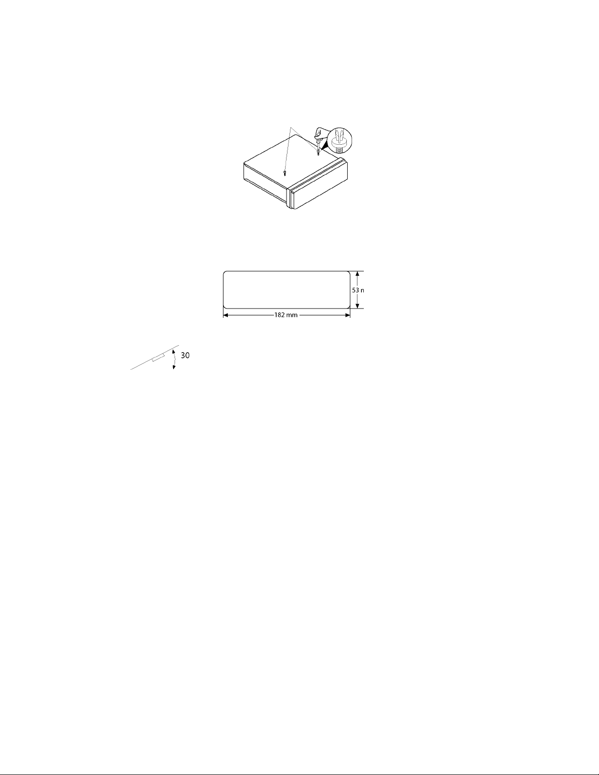
Ifinstallation angle exceeds 30° from
horizontal, the unit might not give its
optimum performance.
Avoid installing the unit where it would
be subject to high temperature, such
as from direct sunlight, or from hot air,
from the heater, or where it would be
subject to dust, dirt or excessive
vibration.
DIN FRONT/REAR-MOUNT
This unit can be properly installed either
from "Front" (conventional DIN Front
mount) or "Rear" (DIN Rear-mount
installation, utilizing threaded screw holes
atthe sides ofthe unit chassis).
For details, refer to the following
illustrated installation methods.
TAKEOUTSCREWBEFORE
INSTALLATION
Before install the unit, please remove the
two screws.
Take out screw before installation
DIN FRONT-MOUNT (Method A)
Installation Opening
This unit can be installed in any dashboard
having an opening as show below:
Installing the unit
Be sure you test all connections first, and
then follow these steps to install the unit.
1. Make sure the ignition is turned off,
and then disconnect the cable from
the vehicle battery's negative (-)
terminal.
2. Disconnect the wire harness and the
antenna.
3. Press the release button on the front
panel and remove the control panel
(see the steps of "to detach the front
panel").
4. Lift the top ofthe outertrim ring then
pull it out to remove it.
5. The two supplied keys release tabs
inside the unit's sleeve so you can
remove it. insert the keys as far as they
will go (with the notches facing up) into
the appropriate slots at the middle left
and right sides ofthe unit. Then slide
the sleeve offthe back ofthe unit.
Page 7
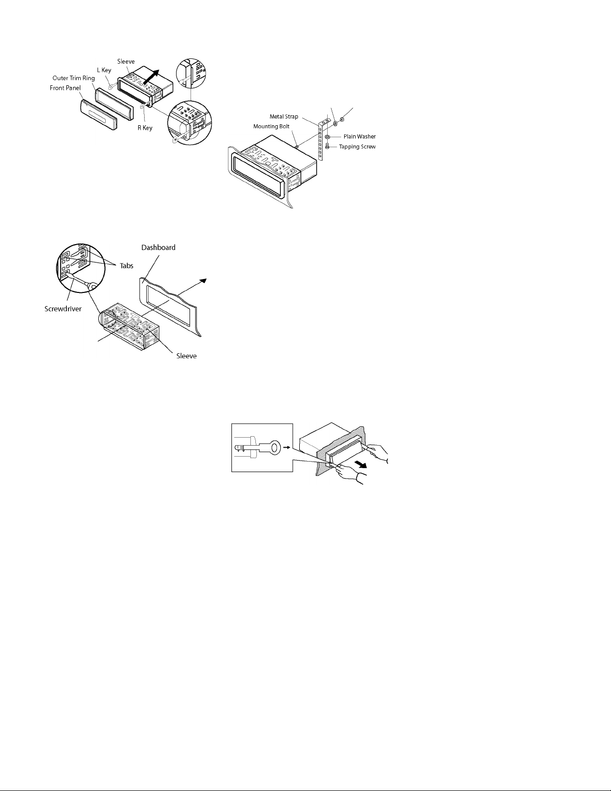
6. Mount the sleeve by inserting the sleeve
into the opening of the dashboard and
bend open the tabs located around the
sleeve with a screwdriver. Notall tabs
will be able to make contact, so
examine which ones will be most
effective. Bending open the appropriate
tabs behind the dashboard to secure
the sleeve in place.
7. Reconnectthewireharnessandthe
antenna and be careful not to pinch
any wires or cables.
8
Slide the unit into the sleeve until it
locks into place.
9,
To further secure the unit, use the
supplied metal strap to secure the back
ofthe unit in place. Use the supplied
hardware (Hex Nut (MSmm) and Spring
Washer) to attach one end ofthe strap
to the mounting bolt on the back of
the unit. If necessary, bend the metal
straptofityourvehicle's mounting
area. Then use the supplied hardware
(Tapping Screw (5x25mm) and Plain
Washer) to attach the other end of
metal strap to a solid metal part ofthe
vehicle underthe dashboard. This strap
also helps ensure proper electrical
grounding ofthe unit.
Note: toinstalltheshortthreading
terminal ofthe mounting boitto the
back ofthe unitand the other long
threading terminal to the dashboard.
SpringWasher ,,
^ Uqv N I It
10. Reconnect the cable to the vehicle
battery's negative (-) terminal. Then
replace the outer trim ring and install
the unit's front panel, (see the steps
of"toinstallthefrontpanel ").
Removing the unit
1. Make sure the ignition is turned off,
then disconnect the cable from the
vehicle battery's negative (-) terminal.
2. Remove the metal strap attached the
back ofthe unit (ifattached).
3. Press the release button to remove the
front panel.
4. Liftthetopoftheoutertrim ringthen
pull it outto remove it.
5. Insert both ofthe supplied keys into
the slots at the middle left and right
sides ofthe unit,then pull the unitout
ofthe dashboard.
Page 8
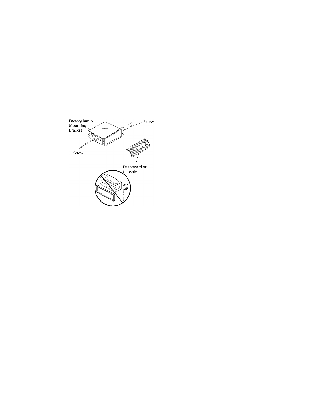
DIN REAR-MOUNT (Method B)
Ifyourvehicle is a Nissan,Toyota, follow
these mounting instructions.
Use the screw holes marked T (Toyota),
N (Nissan) located on both sides ofthe
unit to fasten the unit tothe factory radio
mounting brackets supplied with your
vehicle.
Side view showing
Screw Holes marked T,N
To fasten the unit to the factory radio
mounting brackets.
Align the screw holes on the bracket with
the screw holes on the unit, and then
tighten the screws (5x5mm) on each side.
Note: the outer trim ring, sleeve and the
metal strap are not used for method B
installation.
Page 9

Using the Detachable Front Panel
To Detach the Front Panel
l.Pressthe OPEN button,thenthefront
panel will be folded down.
2.To remove the front panel, lift itupata
little angle from horizontal position,
then first pull out the right side and
then pull out the left side.
2. When the two sides fixed into place,
push the front panel into main unit.
3.Note that ifthe front panel fails to lock
in position properly, pressing control
button may notfunction and the
display may be missing some
segments. Press the OPEN button and
then reinstall the front panel again.
3. For safekeeping, store the front panel
in the supplied protective case
immediately after being removed.
Protective Case
To Install the Front Panel
l.To install the front panel, first insert the
left side into proper position then insert
the right side into place.
Precautions when handling
1. Do not drop the front panel.
2. Do not put pressure on the display or
control buttons when detaching or re
installing the front panel.
3. Do not touch the contacts on the front
panel or on the main unit body. It may
result in poor electrical contact.
4. Ifany dirt orforeign substances
adhered on the contacts, they can be
removed with a clean and dry cloth.
5. Do not expose the front panel to high
temperatures or direct sunlight in
anywhere.
6. Keep awayany volatile agents (e.g.
benzene, thinner, or insecticides) from
touching the surface of the front panel.
7. Do not attempt to disassemble the
front panel.
Page 10

XM AUDIO CABLE (YELLOW)
CO
Page 11

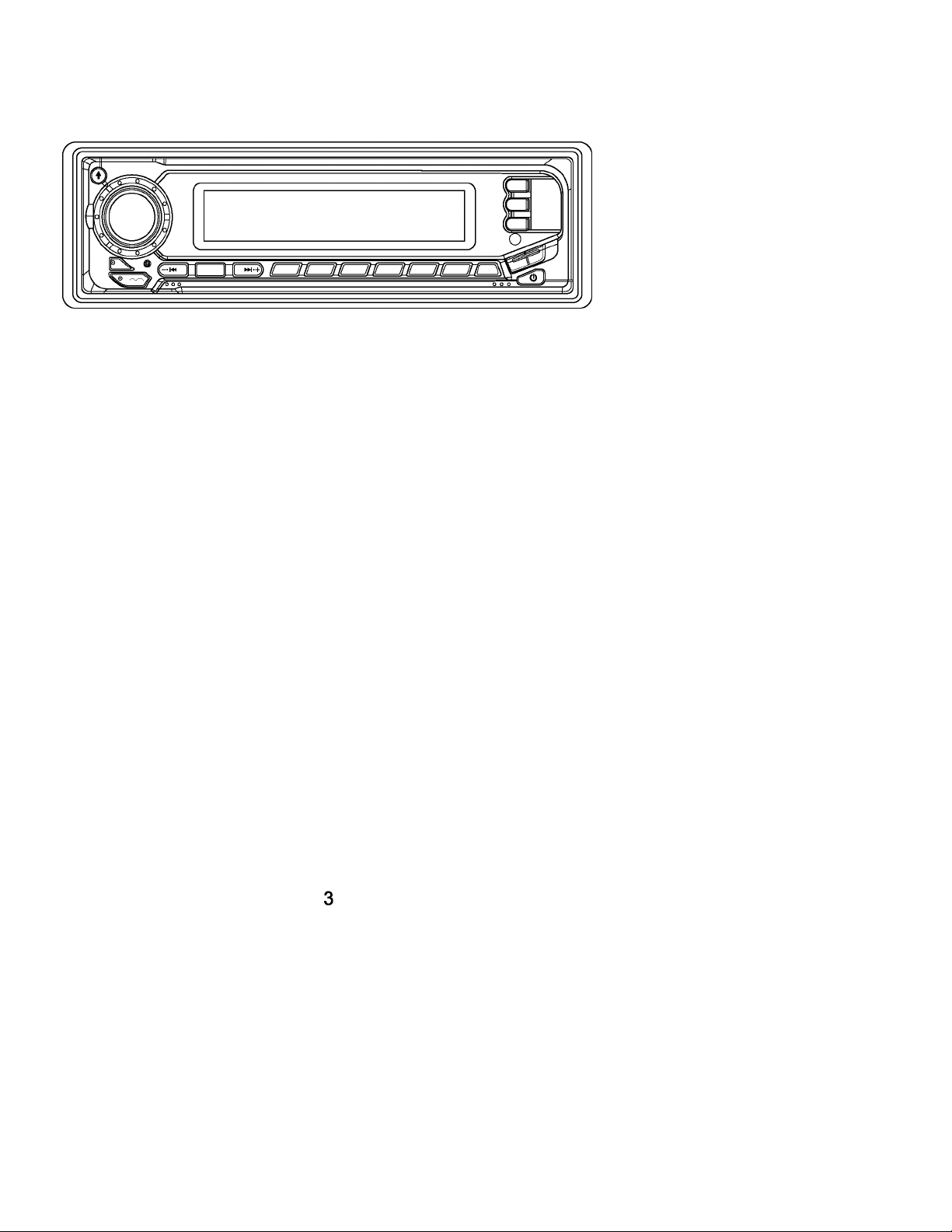
LOCATION OF KEYS
Page 12

SWITHCHING ON/OFF THE UNIT
Switch on the unit by pressing any
button(except OPEN button(7)and £
button (4)). When system is on, press
0 PWR button(9)toturnofftheunit.
FACEPLATE RELEASE
Press OPEN button (7) to detach the
removable faceplate.
SOUNDADJUSTMENT
Press SEL button (10) to select the
desired adjustment mode.
The adjustment mode will change in
the following order:
VO^ _^BA^^TRE _^BAL _^AD
(Volume)^!^ (Bass) ^j^(Treble) (Balance) (Fader)~|
By rotating the VOL knob (11) clockwise
or counter-clockwise, it is possible to
adjust the desired sound quality.
Pressandholdthe SEL button(10)for
several seconds to enter into the
selection for the situation of beep sound,
then rotate the VOL knob (11) clockwise
or counter-clockwise to select as
follows:
BEEP2ND ---------------H>-BEEPALL
---------------
•'► BEEPOPP
- BEEP 2ND mode:
The beep is only generated when all
allowed double function button is
pressed long (several seconds),
e.g.
When preset button is pressed.
When BND/LOU button(13)is
pressed.
When AS/PS button (18) is pressed.
- BEEPALLmode:
The beep is generated when every
button is pressed.
- BEEPOFFmode:
The beep is disabled.
LOUDNESS
Press BND/LOU button(13)for
several seconds to reinforce the bass
output. Press it for several seconds
again to release this function.
DISPLAYINFORMATION
When pressed quickly, the DSP button
(15) changes the display as follows.
- InAM/FMmode:
-> Frequency ->CLOCK ->
- In XM mode:
-> Channel Name -> Category Name
-> Artist Name -> Song Title ->
CLOCK->
- In CD mode:
-> CD->CLOCK->
- lnCDC(orAUX)mode:
-> CDC(orAUX)->CLOCK->
Each displaying time is 5 seconds,
the display will return to the first
position after 5 seconds.
SETTHECLOCK
Pressthe DSP button(15)shortlyuntil
the clock is shown on the display. Then
holddown DSP buttonuntiltheclock
flashes.Then press the TUNE/TRACK
►►I button (17) to change hours or
TUNE/TRAC^ «◄button (16) to change
minutes.
MUTE
Press MUT button(3)tomutedown
the sound instantly. Ifany button is
pressed in the mute state, the mute
state is released.
EQUALIZATION
Press P-EQ button(19)toturnon
equalization function and to select
desiredaudiomode. Therearefive
kinds of mode as below:
♦FLAT-l»- CLASSICS-)»- POPM-)»- R0CKM-)»- DSPOFF^
SUBWOOFER
Press MOD button(6)forseveral
seconds to toggle subwoofer output.
Press it for several seconds again to
release this mode.
LIQUIDCRYSTALDISPLAY
Exhibit current frequency and
activated functions on the display (8).
REMOTE SENSOR
Point the remote cantrol handset to
the remote sensor (26). Press the
function keys on the handset to
control the system.
FLASHING LED
Ifthe front panel does not install in the
main unit, the LED (12) will be flashing.
RESETFUNCTION
RESET button(27)mustbeactivated
10
Page 13

with either aball point pen or thin
metal object.
The RESET button is to be activated
forthefollowing reasons:
- Initial installation ofthe unitwhen all
wiring is completed.
- Allthefunctionbuttonsdonot
operate.
- Errorsymbolonthedisplay.
Note: Ifpress RESET button(27),the
unit can't workyet, please use a cotton
swab soaked in isopropyl alcohol to
clean the socket on the backofthe
front panel.
RADIO OPERATION
SWITCHING TO RADIO MODE
Press MOD button(6)shortlyto
select radio mode, the radio mode
appears in the display together with
the memory band and frequency.
SELECTINGTHE FREQUENCY
BAND
Atradiomode,press BND/LOU
button (13) shortly to select the desired
band. The reception band will change
in the following order:
|-►FM1 FM3-I«- AM —|
Press AS/PS button(18)forseveral
seconds, the radio searches from the
current frequency and checks the
signal strength until one cycle search
isfinished. Andthen6strongest
stations are stored into the
corresponding preset number button.
- Program Scanning
Press AS/PS button(18)shortlyto
scan preset station. When the field
strength level is more than the
threshold level of stop level, the radio
is holding at that preset number for
several seconds with releasing mute,
then searches again.
STATION STORING
Press any one ofthe preset buttons (14)
(1 to 6) to select a station which had
been stored in the memory.
Press this button for several seconds
(until 2ND beeps come out), current
station is stored into the number
button.
MONO/STEREO
Press MON button(l)toselectmono
or stereo mode. You can sometimes
improve reception of distant stations
by selection mono operation.
SELECTING STATION
Press TUNE/TRAC^ button (17) or
TUNE/TRAC^ l◄◄button(16)shortly
to activate automatic seekfunction.
Press for several seconds until
"MANUAL " appears on the display, the
manual tuning mode is selected. If both
buttons have not been pressed for
several seconds, they will return to seek
tuning mode and "AUTO " appears on
the display.
LOCAL/DISTANT
Press LOC button (2) to select
between local and distantstations.
Local setting for reception of strong
station, and a distant setting for
reception ofweaker stations. This
function is effectduring AUTO SEEK
operation.
AUTOMATICMEMORY
STORING- PROGRAMSCANNING
- AutomaticMemoryStoring
ESPFUNCTION
Ifthe unit has the electronic
shockprooffunction,itcan be
shockproofforseveral seconds.
11
Page 14

XM OPERATION
• SWITCHING TO XM MODE
Press MOD button (6) shortly to seleot
XM mode.
• SELECTING USER-PRESET
CHANNEL
At XM mode, the XM user-preset
ohannel group (3 ohannels) is toggled
oyelioally through the group by quiokly
pressing the BND/LOU button (13). The
ohannel will ohange in the following
order:
|-►XM1 -I«- XM2-^>► X^3
• SELECTING CHANNEL UP/DOWN
Press the TUNE/TRAC^^i button (17)
or TUNE/TRAC^^ button (16) to
seleot the ohannel up or down.
• SEARCHING CHANNEL
When the AS/PS button (18) is pressed,
the ohannel searohes for eaoh user
preset ohannel from XM1 to XM2 to
XM3.
When an available ohannel is detested,
the ohannel will be held at that preset
number and play for 5 seoonds. After
that, it will mute and searoh for another
available ohannel.
• STCRING PRESET CHANNELS
The preset buttons (14) oan be used to
store 6 ohannels for oonvenient assess
to your favorite ohannels.
- Programming ohannels
1. Seleot the desired ohannel you
want to store in memory.
2. Press and hold one of the preset
buttons (14) for more than 2
seoonds until the oorresponding
preset button number appears.
Repeat steps 1. and 2. to program
additional ohannels.
- Quioktuning
Press one of the six preset buttons
(14) shortly to seleot a preset ohannel
direotly.
• XM MCDESELECTICN
Press LCC/XM-MCD button (2) to
switoh Category mode, Direot Tune
mode or normal. It is used as the
seleotion of eaoh:
Normal-i* *' Category mod^*^
Direct Типе
c:
When Category mode is engaged, the
“CATEGORY” funotion is turned on in
the display. When Category mode is
released, the “CATEGORY” funotion is
turned off. When Direot mode is
engaged, “DIRECT” of alphanumerio
display is turned on.
Select Category and TUNE UP/DCWN
within selected Category
Use CD/DIR/CAT A button (25) or
CD/DIR/CAT T button (24) to seleot
desire Category and press BND/LCU
button (13).
In Category mode, ohannels oan be
tuned within the same oategory.
- When the user wishes to searoh by
Category, press LCC/XM-MCD button
(2) oan be pressed until it goes into
Category searoh mode.
- Press M6 button (25) or M5 button (24)
up and down to get to the desired
oategory.
- To ohange ohannels, press LCC/XM-
MCD button (2) again to Normal mode,
and then press TUNE/TRACK^w
button (17) or TUNE/TRAC^M-^ button
(16) to seleot the ohannel up or down.
How to direct tune
1. In direct mode, display shows DIRECT
and the channel number.
2. Use^^ button (17) or«^ button (16)
to select the channel.
3. Press BND/LCU button (13) to direct
tune.
и^е
12
Page 15

CD OPERATION CDC OPERATION
• SWITCHINGTOCDMODE
Ifthere is no CD inserted in the driver:
Gently insert the CD with the printed
side uppermost into the CD
compartment until you feel some
resistance. The CD is drawn into the
driverautomatically. CD playback
begins.
If a CD is air eady inserted in the driver:
Keep pressing MOD button (6) shortly
until the CD mode display appears.
• SELECTINGTRACKS
Press TUNE/TRACKm-^ button (16) or
TUNE/TRAC^ button (17) to move
to the previous track or the following
track. Track number shows on display.
HoldTUNE/TRACKM-<button(16)or
TUNE/TRAC^ button (17) to fast
reverse or fast forward. CD play starts
from when you release the button.
• PAUSINGPLAYING
Press PAU button(20)topauseCD
player. Press itagain to resume play.
• PREVIEWINGALLTRACKS
Press SCN button(21)toplayfirst
several seconds of each trackon the
current disc. Press again to stop intro
and listen to track.
• REPEATINGTHESAMETRACK
Press RPT button (22) to continuously
repeat the same track. Press it again to
stop repeat.
• PLAYING ALL TRACKS IN RANDOM
Press SHF button (23) to play all tracks
on CD in random order. Press again to
cancel the function.
• EJECTINGADISC
Press± button (4) to stop CD playing
and eject the disc from the disc slot (5).
You can connect a CD changer to the unit
with CDC operation version only.
Information on handing CDs, inserting
CDs and operating the CD changer can
be found in the operating instructions
supplied with your CD changer.
• SWITCHINGTOCDCMODE
Keep pressing MOD button (6) shortly
until the CDC mode display appears.
•
Playback begins with the first CD that
the CD changer detects.
• SELECTINGTRACKS
Press TUNE/TRAC^ ¡◄◄button (16) or
TUNE/TRAC^ button (17) to move
to the previous track or the following
track. Track number shows on display.
Hold TUNE/TRAC^ !◄◄ button (16) or
TUNE/TRAC^ button (17) to fast
reverse or fast forward. CD play starts
from when you release the button.
• PAUSINGPLAYING
Press PAU button (20) to pause CD
player. Press itagain to resume play.
• PREVIEWINGALLTRACKS
Press SCN button(21)shortlytoplay
first several seconds of each track on
currentdisc.Pressandhold SCN
button (21)for several seconds to play
first several seconds of the first track
on each disc in the CD magazine.
Press it again to stop intro and listen
to track.
• REPEATINGINDIVIDUALTRACKS
ORWHOLE CDs
Press RPT button(22)shortlyto
continuously repeat the same track.
Pressandhold RPT button(22)for
several seconds to continuously repeat
all tracks on the current disc.
Press itagain to stop repeat.
• PLAYING ALL TRACKS IN RANDOM
Press SHF button (23) shortly to play
all tracks on the current disc in random
order. Press and hold SHF button (23)
for several seconds to select a disc in
random and play the selected disc in
random order. Press it again to cancel
the function.
• SELECTINGDISC
Press CD- button (24) to select previous
disc and CD+ button (25) to select next
disc.
13
Page 16

MP3 OPERATION
• SWITCHINGTOCD(MP3)MODE
Ifthere is no MP3 disc inserted in the
driver:
Gently insert the MP3 disc with the
printed side uppermost into the disc
slot (5) until you feel some resistance.
The MP3 disc is drawn into the driver
automatically. The MP3 playback
begins.
Ifa MP3 disc is air eady inserted in the
driver:
Keep pressing MOD button (6) shortly
until the CD (MP3) mode display
appears.
• EJECTINGADISC
Press± button (4) to stop MP3 playing
and eject the disc from the disc slot (5).
• SELECTINGTRACKSINSINGLE
STEP
Press TUNE/TRAC^ button (16) or
TUNE/TRAC^ button (17) to move
to the previous track or the following
track. Track number shows on display.
• SELECTING DIRECTORY UP/DOWN
Press MS button (24) or M6 button (25)
to select directory downward or upward.
Ifthe MP3 disc does contain any
directory, there is no function of pressing
MS button (24) or M6 button (25).
• PAUSINGPLAYING
Press PAU button(20)topauseMP3
player. Press it again to resume play.
• PREVIEWINGALLTRACKS
Press SCN button(21)toplayfirst
several seconds of each track on the
current disc. Press again to stop intro
and listen to track.
• REPEATINGTHESAMETRACK
Press RPT button (22) to continuously
repeat the same track. Press it again to
stop repeat.
• PLAYING ALL TRACKS IN RANDOM
Press SHF button (23) to play all tracks
on MP3 disc in random order. Press
again to cancel the function.
SELECTING TRACKS BY AS/PS/MP3
BUTTON
AS/PS buttonisassignedasDigital
Audio Mode selection button in MP3
operation.
When pressed, it is activated as
selecting each mode of Digital Audio.
Searching track directly "=> Searching
Directory or File Name "=> Navigation"
from root by TUNE/TRACK UP/DOWN
•
buttons=> Navigation" from current
directory by TUNE/TRACK UP/DOWN
buttons.
Searching Track Directly
Press AS/PS (MP3) button for one time.
Itentersinto Searchingtrack
directly" in Digital Audio CD.
The unit searches the track selected by
following direct numeric buttons:
Ml-M6,MOD (7),TUNE/TRACK
DOWN (8), TUNE/TRACK UP (9),
DSP(O).
If selected three digits, the unit searches
the tract at once. If selected one or two
digits,the unitwaitfor ENT(BND/LOU)
button for seconds. The unit searches
the track after few seconds, even if the
enter button is not pressed.
Searching Directory or File Name
Press AS/PS(MP3) buttonfortwo
times. It enters into Searching Directory
or File Name " in Digital Audio CD.
The unit searches files and directories
that have the same character which is
inputted by the user pressing the
corresponding buttons listed on the
Table 1 below.
Explain as follows:
- Usethecorrespondingbuttonsto
select the characters A to Z, blank,
0 to 9, _, -, +.
- Press SEL button to confirm
entry of each characters.
- Press BND/LOU (ENT) button to start
the title search.
In case the selected title is a directory
name,displaywillshow( ""),then
- Usethe TUNE/TRACK UP/DOWN
buttons to list all songs under this
14
Page 17

directory and select the title.
- Press BND/LOU (ENT)3utton to
confirm and start the play.
- Repeat the above steps if the newly
selected title is again a directory.
Searching From Root Directory
Press AS/PS (MP3) button for three
times. The unit searches file or
directory from root by TUNE/TRACK
UP/DOWN buttons. (D-DIR icon turns
on if the name is directory). Display will
list all available directories and songs.
Select the desired directory/songs by
using TUNE/TRACK UP/DOWN
buttons and BND/LOU (ENT)3utton
to confirm. If the selected title is a song,
it starts to play.
If the selected title is a directory name,
display will show (‘ ‘), then
- Use the TUNE/TRACKJP/DOWN
buttons to list all songs under this
directory and select the title.
- Press BND/LOU (ENT) button to
confirm and start the play.
- Repeat the above steps if the newly
selected title is again a directory.
Searching From Current Directory
Press AS/PS (MP3) button for four
times. The unit searches file or directory
from current directory by
TUNE/TRACIOP/DOWN buttons. (DDIR icon turns on if the name is
directory). The current directory name
is displayed for a second and the
currently playing file name is displayed
(selected). The user can select the
directory or file in the directory by
TUNE/TRACK UP/DOWN buttons. The
selected file can be played by pressing
BND/LOU (ENT) button.
KEY Assigned IN Searching mode (Table 1)
AS/PS Mode Select
BND/LOU ENTER
Ml
M2
M3 G, H, 1, 3
M4 J, K, L,4
M5 M, N, O, 5/
M6
MOD S, T, U, 7
TUNE/TRACK
DOWN V, W, X, 8
TUNE/TRACK
UP Y, Z, SPACE, 9
SEL CHARACTER
DSP
AUDIO CHARACTER SELECT
KNOB (A, B-8,9, 0)
AUDIO KNOB (ENCODER) &
TUNE/TRACK UP/DOWN buttons:
Searching file and directory during
Navigation.
A, B, C, 1
D, E, F, 2
Directory DOWN
P, Q, R, 6/
Directory UP
SHIFT RIGHT
+, 0
DISPLAY INFORMATION
Press DSP button to show following
information, such as the clock, ID3 TAG
(if available: song title, directory name,
artist name, other contents^) and other
information.
15
Page 18

MIXED-CD OPERATION
Ifavailable, the unit can play the mixedCD disc (the disc contains both CD audio
tracksand MPSfiles).
When you insert a mixed-CD disc into
the CD slot, it starts to play the CD audio
tracks. And the operation is the same
with the CD operation described as
above.
Ifyou want to switch to play MP3 files,
press MS button (24) or M6 button (25),
it will search the disc over again and start
to play the MP3 files. And the operation
is the same with the MP3 operation
described as above.
Ifyou want to revert to play CD audio
tracks, press MS button (24) or M6
button (25) repeatedly, when itjumps to
the end (i.e. when it selects the first
directory or the last directory), and then
press MS button (24) or M6 button (25)
again, it will start to play the CD tracks
again.
In this way,you can switch between
playing CD audio tracks or MP3 songs
repeatedly.
DISC NOTE
A. Notes on discs:
1. Attempting to use non-standard shape
discs (e.g. square, start, heart) may
damage the unit. Be sure to use round
shape CD discs only for this unit.
2. Do not stick paper or tape etc., onto
the label side or the recording side of
any discs, as it may cause a
malfunction.
3. Dirt, dust, scratches and warping discs
will cause misoperation.
B. NotesonCD-Rs(recordable
CDs)/CD-RWs (rewritable CDs):
1. Be sure to use discs with following
marks only for the unit to play:
DIGITAL AUDIO
nCOMPACT nCOMPACT
mME
DIGITAL AUDIO DIGITAL AUDIO
2. The unit cannot play a CD-R and
CD-RW that is not finalized.
(Please referto the manual ofyour
CD-R/CD-RW recorder or CD-R/
CD-RW software for more information
on finalization process).
3. Depending on the recording status,
conditions ofthe disc and the
equipment used for the recording,
some CD-Rs/CD-RWs may not be
played on this unit. (See *1)
*1: Tohavemorereliableplayback,
please see following
recommendations:
a. Use CD-RWs with speed lxto4x
and writewith speed Ixto 2x.
b. Use CD-Rs with speed Ixto 8x and
write with speed lx to 2x.
c. Do not play a CD-RW which has
been written for more than 5 times.
C. NotesonMP3files(MP3Version
Only):
1. The disc must be in the ISO9660 level
1 or level 2 format, or Joliet or Romeo
in the expansion format.
2. When naming a MP3 file, be sure the
filenameextensionis ".MP3".
3. For a non-MP3 file, even though the
file name extension is ".MP3 ", the unit
cannot recognize it.
16
Page 19

FUNCTION KEYS & CONTROL
® ® ® ®
1. PWR
2. DSP (0)
3. SEL
4. VOL ^
5. VOL ^
6. BND (ENTER)
7. MOD (7)
8. TUNE/SEEK
9. TUNE/SEEK
10. AMS(MP3)
11. Ml -M6
12. PAU
13. SCN
14. RPT
15. SHF
16. DISC -
17. DISC +
= PowerON/OFFButton
= DisplayButton(_, -,+,0)
= Select Button (Character Shift Right)
= Volume Up Button [Character Select (A, B~8,9,0)]
= Volume Down Button [Character Select (A, B~8,9,0)]
= BandSelectButton(EnterButton)
= Mode Button (S, T, U, 7)
= Tune/Seek Down Button (V, W, X, 8)
= Tune/Seek Up Button (Y, Z, SPACE, 9)
= Automatic Storing & Program Scanning Button
(Mode Select Button)
= Preset Buttons (A~R, 1~6)
= PauseButton(A,B,C,l)
= ScannlngButton(D,E,F,2)
= Repeat Button (G, H, 1,3)
= Shuffle Button (J, K, L, 4)
= Disc Down Button
= DIscUpButton
17
Page 20

18
Page 21

Troubleshooting
Before going through the checklist, check wiring connection. If any of the problems
persist after checklist has been made, consult your nearest sen/ice dealer.
Symptom
No power. The car ignition switch is
Disc cannot be
loaded or ejected.
No sound. Volume is in minimum. Adjust volume to a desired level.
Sound skips. The installation angle is
noton.
The fuse is blown. Replace the fuse.
Presence of CD disc inside
the player.
Inserting the disc in reverse
direction.
Compact disc is extremely
dirty or defective disc.
Temperature inside the car
is too high.
Condensation Leave the player off for an hour
Wiring is not properly
connected.
more than 30 degrees.
Cause
If the power supply is
connected to the car accessory
circuits, but the engine is not
moving, switch the ignition key
to "ACC ".
Remove the disc in the player,
then put a new one.
Insert the compact disc with
the label facing upward.
Clean the disc or try to play a
new one.
Cool off or until the ambient
temperature return to normal.
or so, then try again.
Check wiring connection.
Adj ustthe installation angle less
than 30 degrees.
Solution
The operation keys
do not work.
The radio does not
work. The radio
station automatic
selection does not
work.
The disc is extremely dirty
or defective disc.
The built-in microcomputer
is not operating properly
due to noise.
The antenna cable is not
onnected.
The signals are too weak. Select a station manually.
Clean the compact disc, then
try to play a new one.
Press the RESET button.
Front panel is not properly fixed
into its place.
Insert the antenna cable firmly.
19
Page 22

Warning / Disclaimer
WARNING
Investigate the layout of your automobile thoroughly before drilling or cutting any holes.
Take care when you work near the gas tanks, gas lines, hydraulic lines, and electrical wiring.
Attach the system securely to the automobile to prevent damage, particularly In the event
of an accident. Do not mount the system so that the wire connections are unprotected
or are subject to pinching or damage from nearby objects.
The +12V DC power wire must be fused at the battery positive terminal connection.
Before making or breaking power connections at the system power terminals,
disconnect the +12V wire at the battery end. Confirm your radio/head unit and/or other
equipment is turned off while connecting the input Jacks and speaker terminals.
If you need to replace the power fuse, replace it only with a fuse identical to that
supplied with the system. Using a fuse of different type or rating may result in damage to
this system which is not covered by the warranty.
Disclaimer
Specifications are subject to change without notice.
For the most updated Specifications call Audiobahn,
your local Authorized Audiobahn Dealer,
or check the Audiobahn website.
tech@audiobahn.com
20
Page 23

Damage caused by improper installation
Any cost or expense related to removal or reinstallation
• Any unauthorized services
• Any product that has the serial number removed, altered, or defaced
• Subsequent damage to any other components
• Pinched, cut, or stripped wires
• Any product that Is new, and/or found to be In working condition
• L.E.D. indicators on electronics
21
Page 24

 Loading...