

Audio Authority Access EZ 955, Access EZ 922, Access EZ 945, Access EZ 956B, Access EZ 932 System Installation Manual
...Page 1

Demonstration Network
Home Audio and Video
System Installation Manual
Page 2

Page 3

Contents
Orientation
Planning
Installation
INTRODUCTION ......................................................................................................................... 4
HOW THE ACCESS™ SYSTEM WORKS ...................................................................................5
ACCESS™ SYSTEM COMPONENTS ......................................................................................... 6
SINGLE PRODUCT GROUP SWITCHING SYSTEM .................................................................8
MULTI-COMPONENT 2-CHANNEL SWITCHING ....................................................................10
HOME THEATER SWITCHING SYSTEM ................................................................................. 12
VIDEO DISTRIBUTION SYSTEM ............................................................................................. 14
ADDING CONTROL INTERFACES ..........................................................................................14
PREPARATION .........................................................................................................................15
ADDRESSING ...........................................................................................................................15
INSTALL THE SYSTEM HARDWARE ......................................................................................18
INSTALL THE BUS CABLES ....................................................................................................18
CHECK YOUR WORK TO THIS POINT ...................................................................................21
INSTALLING A CONTROL METHOD ....................................................................................... 23
INSTALLING REMOTE SWITCHES .........................................................................................25
TESTING SYSTEM FUNCTION ...............................................................................................26
DEMO PRODUCT INSTALLATION ...........................................................................................29
USER TIPS ...............................................................................................................................31
Reference
The software imbedded within the Access System is not sold, but rather licensed for this product specic use. The original purchaser is licensed to use this
software in this product and this application only. Under this license, the software may not be reproduced, copied, disassembled, distributed by any means,
licensed, rented, sold, or in any way revealed to or used by a third party.
The words “Audio Authority” in any font, the Audio Authority logo, and the “double-A” symbol, are registered trademarks of
Audio Authority Corporation. Access Demonstration Network, AccessEZ, AutoDamping, SPL Auto Limiting, TheftAlert, AccessEZ and SilenTouch are
trademarks of Audio Authority Corporation.
Dolby is a trademark of Dolby Laboratories, Incorporated. HDMI, the HDMI logo and High-Denition Multimedia Interface are trademarks or registered
trademarks of HDMI Licensing LLC. Toslink is a trademark of Toshiba America.
APPENDIX A: SAMPLE SYSTEMS .........................................................................................34
APPENDIX B: PRODUCT CONNECTION DIAGRAMS ............................................................38
DEFINITION OF TERMS ..........................................................................................................46
ACCESS™ WARRANTY ...........................................................................................................48
INDEX .......................................................................................................................................49
3
Page 4
ORIENTATION
This manual is provided as a framework to help you successfully install your Access System,
test its operation, and then use the system to demonstrate and sell your merchandise. This
manual covers the proper installation of the switching system hardware only. If your system
includes a 903 or 906G Control Panel, or touchscreen interface, please refer to the separate
audioauthority.com/access_tips
• Tips
• Examples
• FAQ
User Guide provided with your control panel for operation instructions.
Please read and follow these instructions carefully. If you have any difculties during the installation, don’t hesitate
to call us for assistance! We’re open Monday through Friday from 8:30 AM until 5:00 PM, Eastern Time. Also check our
website for diagrams and tips: audioauthority.com/access_tips.
Introduction
The AccessEZ™ series of demonstration system modules provides a plug-in solution for home, portable audio and car
audio switching systems in retail display environments. This second generation of the highly capable, industry-acclaimed
Access™ System modules offers many new features and benets:
• AccessEZ offers a compact module to t each kind of product, compared with a patchwork of printed circuit boards.
• Modules are protected by attractive and rugged steel covers.
• Expansion, when needed, is done by directly “docking” Expander modules.
• Comprehensive control panels with automated demonstration features.
• Single product group control panel for soundbars, in-wall speaker displays, or any product category.
• Your choice of button-per-product, central control panel/third party touchscreen, or any combination of user interface.
• Sophisticated SilenTouch™ interval muting for quiet switching.
• Capacity for hundreds of products.
All of these features make it easy to design the demonstration system that ts your specic merchandising needs. Your
Account Manager and our Application Engineering staff can assist you in selecting and conguring the appropriate
AccessEZ™ modules to build the ideal system for you.
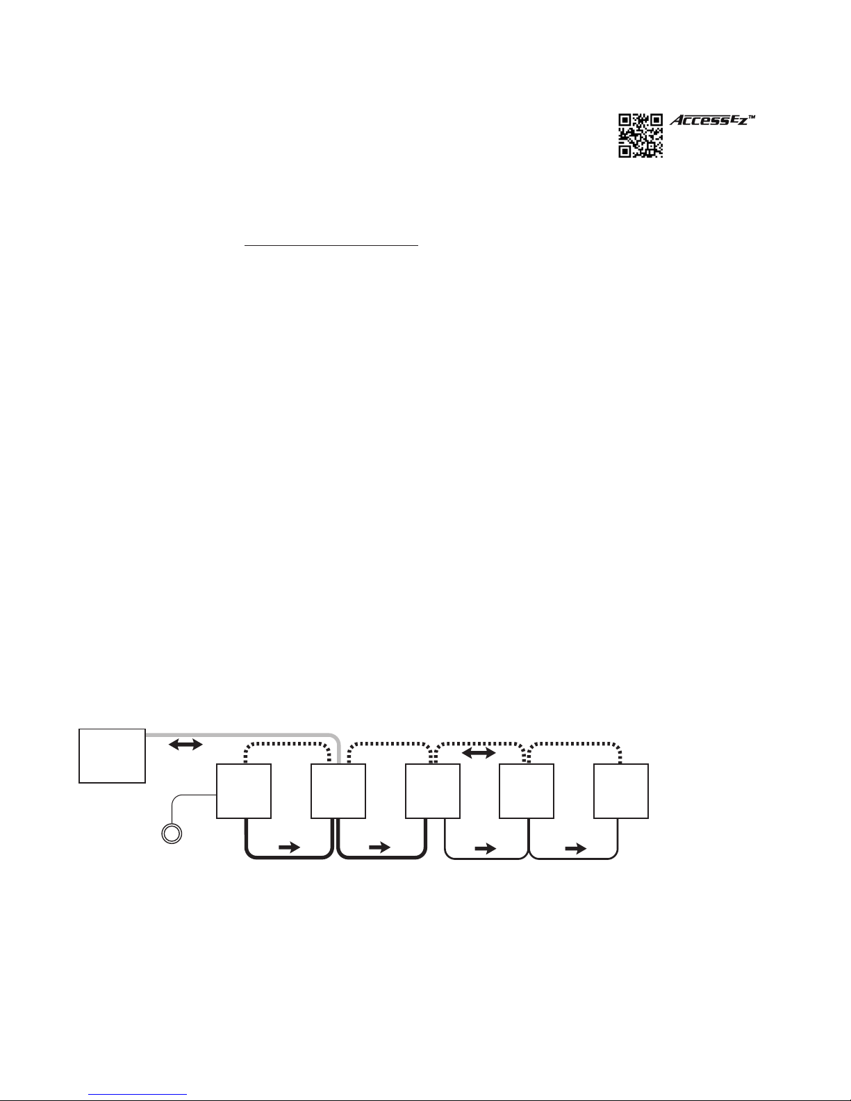
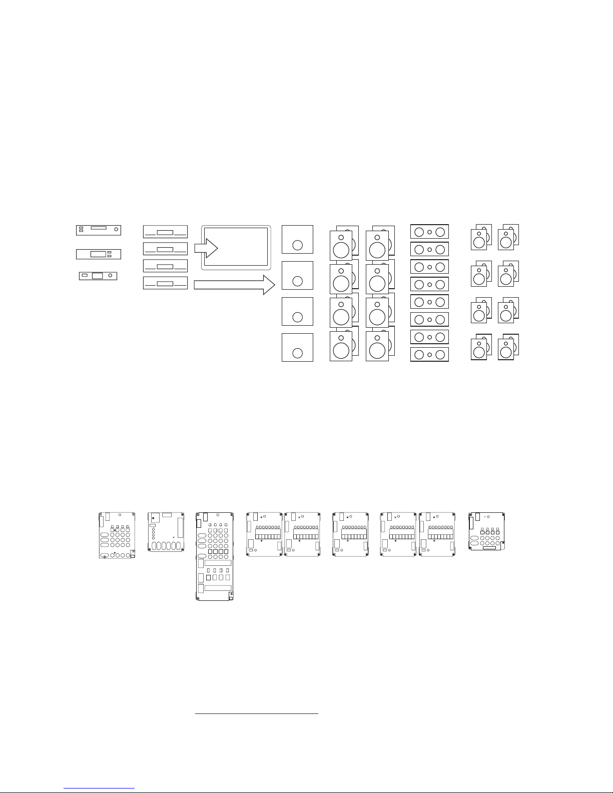
What is the Access™ System?
The Access™ System is a network of intelligent modules including product selectors, control modules, and signal expander
modules. These modules communicate with each other via the “system bus”, allowing you to construct and control the
exact demonstration system conguration you desire from the sources, receiver/ampliers, speakers, subwoofers and
video monitors in your display. The modular architecture allows the switching modules to be located near the actual
products on display creating a “distributed switching network.” The products are connected to the modules rather than
being wired to one central point, simplifying installation. Selected product signals are then sent across the network through
“buses” that interconnect the modules.
Control
Panel
Source
Switching
Module
Product
Select
Button
Figure 1. Basic overview of the Access Demonstration System
System
Module
Receiver
Switching
Module
Left
Speaker
Switching
Module
Right
Speaker
Switching
Module
4
Page 5
Buses
Signals are passed between modules through “buses,” which are nothing more than cables that go from module to
module to module, connecting them into functional groups within the system’s architecture.
The System Bus connects all switching and system modules, allowing them to send messages to each other, controlled
by the addresses that are set by the installer. These signals instruct the modules to select the inputs/outputs of a particular
unit, such as a source or receiver. Expander modules are not connected directly to the System Bus. Each expander
receives its instruction from the main switch module to which it is attached.
Signal Buses carry audio signals, either low-level (source low-level output, for example), high-level signals (amplier
output), or video signals.
System Bus
922
Low-Level Bus (Source Bus/Receiver In Bus) High-Level Speaker Bus
Figure 2. Basic bus examples in a simple demonstration system
980
942
932
Left Right
932
HOW THE ACCESS™ SYSTEM WORKS
When a product is selected for demonstration, signals are sent through a network of buses between switching modules to
activate that particular product position.
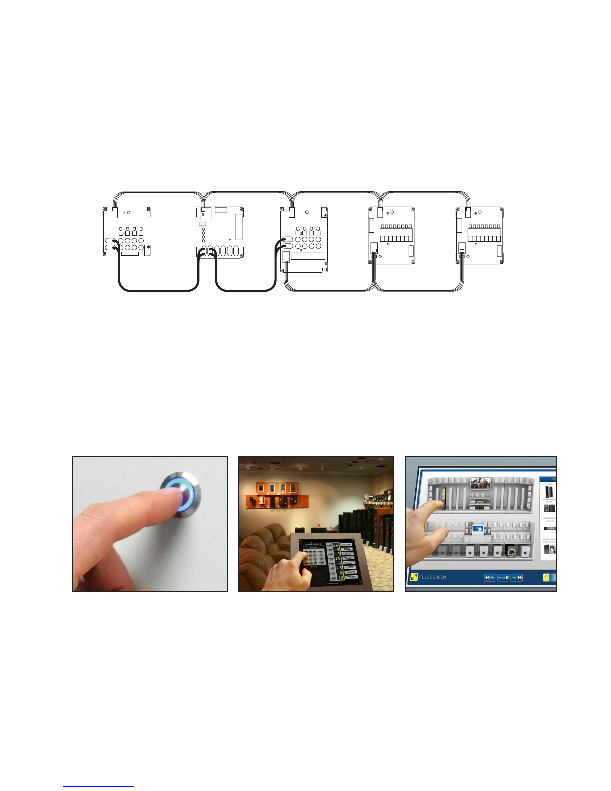
Selecting Products in the Access™ System
Products can be selected in a system in different ways that can all be combined into a single system, if desired. You may
select products in the following ways or a combination of these methods:
Figure 3. Figure 4. Figure 5.
By pressing a Product Select Button
(PSB) connected to a switching
module. PSBs may be used in the
same system with any control panel or
as the sole method of control.
*A touchscreen interface requires custom software that may be created by the user or by Audio Authority.
Custom software charges apply.
By using a control panel, if the system
is so equipped. Control panel use is
covered in detail in a separate manual
that accompanies each control panel.
By using a computer touchscreen
with custom software* congured to
enable product selections and other
control functions.
5
Page 6

Access™ System Components
User Interfaces
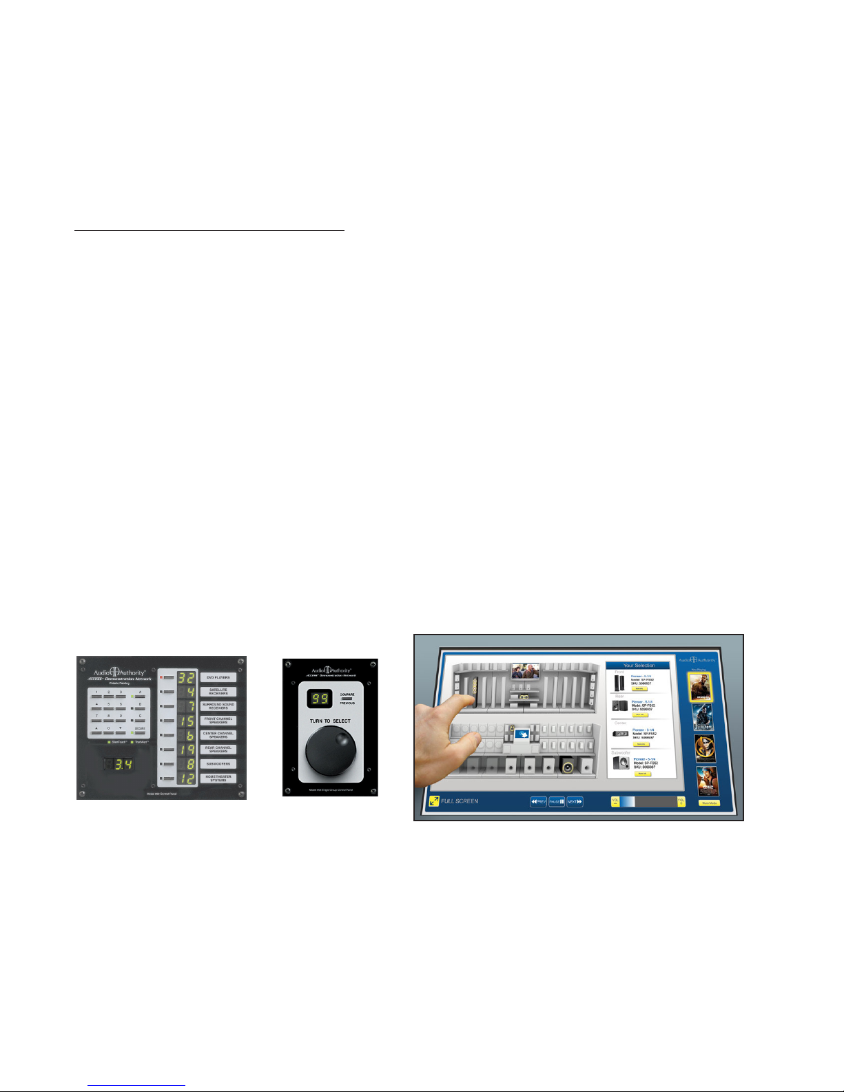
903 Control Panel
• Displays selected products, even
when selected using Product
Select Buttons or other methods.
Displays diagnostic information for
troubleshooting the system.
• Removable product group insert
labels can be changed to indicate
the functions of the LED displays. An
extensive set of labels is included with
the control panel.
• If not assigned as an active product
group, the control panel’s last
product group can store up to 99
pre-congured systems for
immediate recall.
• The control panel or any specic
product group can be “locked out”
from unauthorized user input.
906G Control Panel
Perfect for DVD displays, speaker walls, or
home theater package systems. The 906G
Control Panel selects products from one
Product Group, using a rotary encoder knob, and displays the selected product
number in the LCD window. Use the Select Previous button to make instantaneous
comparisons between products. Two 906G Control Panels may be used in one
system, one 906G for each Product Group.
Product Select Buttons
A product select button is a momentary switch, usually with an LED to indicate
when a product is selected. Each button has a four-conductor (or two-conductor)
cable connecting the button to the switch module (See page 25 if using
two-conductor buttons.) Audio Authority carries several button styles and colors,
check with your Account Manager for colors and availability.
Touchscreen Graphical User Interface
The Access system allows any device to send and
receive commands via RS-232. This includes
a computer with a touchscreen GUI. You can
develop your own interface and connect the
device to our Model 970A Serial Interface
Module via serial cable. Developing a GUI may
be impractical for one or two displays, but it can
be an excellent solution for retailers that have
dozens of locations.
Figure 6. The 903 controls up to eight product groups.
Figure 7. 906G
Figure 8. PSB-224
6
Figure 9. Touchscreen GUI
Page 7

System Module
Model 980B System Control Module
System Module performs vital tasks within the Access™ System such as SilenTouch™, speaker limit, and provides
an interface for a 903 Control Panel. One per system.
Special Modules and Devices
These modules provide extra capabilities, and are not required for many systems.
970A-1 RS-232 Serial interface/PC Interface
With custom software the 970 connects the Access system to a PC for computer control (Touchscreen, etc.).
HDMI Switching Control Module
The 970A-1 can be programmed to interface with an HDMI switcher, so that HDMI sources can be controlled
via product select button or control panel in harmony with the Access demonstration network. Ask your Account
Manager about custom programming for HDMI.
977 Digital Audio Adapters
977R converts optical (Toslink) digital audio signals to coax, and 977T converts coax digital audio signals to
optical.
979 Audio Converters
979R converts 2-channel digital audio signals to analog, and 979T converts analog audio to digital PCM.
1322D EDID Control Module
1322D EDID Controller edits the EDID table to present the preferred settings to a source device.
Signal Expander Modules
Expander modules add channels to main switch modules. They are circuit board products with no steel case.
920X Low-Level Expander
2-channel low-level expander used to add more channels to a main switch module.
932X Speaker-Level Expander
Eight speaker expander used to add extra speaker (E.G. Rear) channels to Model 932.
940X High-Level Expander
2-channel high-level expander used to add channels to a main switch module.
949X High Current Speaker-Level Output Expander
2-channel expander used to add a high current subwoofer amplier channel to Model 922 or 942.
Switching Modules
The following modules are the main backbone of an AccessEZ switching system. They are connected together via a
System Bus over which they communicate with each other and the control panel (if used).
Source Switching Modules
Model 922 (Low-Level) Selector Module
Model 922 controls four 2-channel audio sources. May also be used for switching powered subwoofers.
Model 955 Source Selector Module
Model 955 controls four audio/video sources, including digital audio (coax) as well as composite
video. Bus connections are directional (IN from previous source module/OUT to next source module or to next
product group.)
7
Page 8

Receiver, Amplier and Soundbar Modules
Model 942 Amplier Selector Module
Model 942 controls four two-channel ampliers or receivers. One module accommodates both low-level inputs
and high-level outputs. For high current amplier applications, use 922 for input, but dock a heavy duty 949X
module to it to switch the high current speaker output signals (See also 939 below.)
Model 945 Receiver Selector Module
Model 945 controls four Surround Sound or Digital Audio receivers. One module accommodates low-level and
Digital Audio inputs and front/center/surround high-level outputs, as well as low-level Subwoofer output. Bus
connections are directional (IN from previous receiver module or previous product group/OUT to next
receiver module).
Model 956 Soundbar Selector Module
Model 956 controls four soundbars, digital-to-analog converters, or receivers (with dedicated speakers). One
module accommodates digital (Toslink®) and stereo analog inputs allowing PCM, Bitstream, Dolby TrueHD and
DTS TruSurround.
Speaker Modules
Model 932 Speaker Selector Module
Model 932 controls one channel (e.g. left or right) of eight speakers. Two 932 modules are required for eight
stereo pairs. Use one 932 for center speakers or speaker level subwoofers.
Model 939 High Current Speaker Selector Module
For high current applications, use 939 in place of 932 switch modules (See also 949X on page 7.)
Model 940 High-Level Selector Module
Model 940 controls four speaker pairs, but does not offer SilenTouch™ or AutoDamping™. Use Model 932 for
applications where SilenTouch™ and AutoDamping™ are desired.
SINGLE PRODUCT GROUP SWITCHING SYSTEMS
Individual Access Modules
Most products can be switched with a single AccessEZ™ module, and generally, a 980 System Module. Product Select
Buttons (PSBs) may be installed next to each product or a 906G Single Product Group Control Panel can be used. If
the system is expanded to switch multiple sources, receivers and speakers, the Access™ system can be modied by
adding the necessary switching modules. This section provides a general overview of system layouts; for detailed hookup
instructions, see Appendix A.
Dedicated Source
980
Dedicated Amplifier
System Bus
Low-Level
Speaker-Level
Figure 10. Mono outdoor speaker display.
8
Mono Outdoor Speakers
932
Page 9
Audio Sources
956
Digital A-V
Source
Soundbar
Soundbar
Soundbar
Soundbar
Video Monitor
System Bus
Low-Level
Digital Audio
Speaker-Level
HDMI
EDID
Device
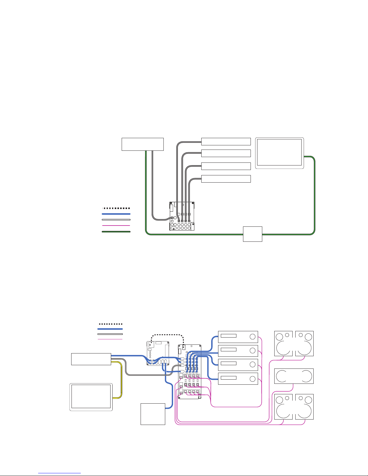
Use a 922 Low-Level module for every four CD players, music servers, or satellite radio receivers you plan to
include in your switching system (Figure 10). Connect each source to a 922, and connect the system bus and
low-level bus from the 922 module to the “Bus In” jacks on the 980 System module. Connect an RCA patch cord
from the low-level “Bus Out” jacks on the 980 to the CD input of a dedicated receiver and add a pair of speakers
to complete the display. To add more sources, add 922 modules. For example, to add sixteen sources, connect
system bus and low-level bus from the rst 922 to four more 922 modules.
TV Soundbars
Use a 956B module (Figure 11) for every four soundbars to be demonstrated. The HDMI video from the source
connects to the TV. The 956B switches any digital audio format including Dolby®. To add soundbars to your
display, add 956B modules. For example, to add eight soundbars, add two 956B modules. Connect all modules
with system bus, and all 956B modules with audio/video bus. Be sure to follow signal ow when connecting bus
jacks labeled IN/OUT.
Figure 11. Four Soundbars with dedicated TV. Insert an EDID control device in the HDMI pathway to choose an audio soundstage;
otherwise the TV may cause the source to output 2-channel PCM.
Surround Receivers
Use one 945 module for the input/output for every four receivers (Figure 12). The analog audio bus connects the
dedicated source to the 980 module, and from there it links all the 945 modules in the receiver group. Be sure
you properly connect the bus according to signal ow. The digital audio bus comes directly from the dedicated
source to the 945 module’s IN jacks. Connect all main modules with system bus and speaker bus (for more
detail, nd “bus cable installation” in the index.) To add receivers, just add switching modules. For example, to
add 12 receivers to a surround switching system, add three 945 modules.
System Bus
Low-Level
Digital Audio
Speaker-Level
Dedicated
Source
Video Monitor
980
Powered
Subwoofer
945
Receiver Group
Surround
Left/Right
Surround
Speakers
Center
Speaker
Left/Right
Front
Speakers
Figure 12. Four surround sound receivers with dedicated source, TV, and speakers.
9
Page 10
Stereo Receivers
Use one 942 module for the input/output for every four stereo receivers (not shown). The low-level bus connects
the dedicated source to the 980 module, and from there it links all the 942 modules in the receiver group.
Connect all main modules with system bus and speaker bus (for more detail, nd “bus cable installation” in
the index.) To add receivers, just add switching modules. For example, to add sixteen receivers to a 2-channel
switching system, add four 942 modules.
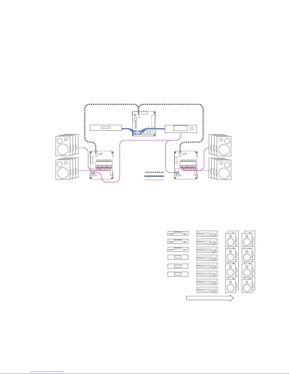
Stereo Speakers
The 932 Speaker Module lets you place switching modules close to the merchandise, dramatically reducing
wiring runs. Each 932 handles up to eight speakers in one channel (Figure 13). For every eight speaker pairs,
use two 932 modules, one for the left speakers and one for the right. Install the 980 module between the source
and the receiver in the low-level bus as shown. Connect the 980 and all 932 modules with system bus. To add
speakers, add 932 modules. For example, to add sixteen speaker pairs, add two left 932s and two right 932s. To
demonstrate four speaker pairs (or fewer), use a 940 module (not shown) and a 980 module.
Figure 13. All modules are
connected by System Bus.
Dedicated Source
980
Dedicated Receiver
932 932
System Bus
Low-Level
Speaker-Level
MULTI-COMPONENT 2-CHANNEL SWITCHING SYSTEM
Designing Your Own Application
Home audio demonstration systems can be designed in different
ways. This section explains the basic switching congurations
for a 2-channel display including several sources, receivers, and
stereo speakers. The architecture of Access™ makes it possible
to design a system that ts your needs exactly. Your Account
Manager can help you choose the modules and user interfaces
that will best suit your needs and product mix. If you wish to
change your merchandising approach in the future, Access™
can be rewired and additional modules can be installed to
accommodate a different conguration.
Stereo Receivers Stereo Speaker Pairs Stereo Sources
Organize Products into Groups
When planning the installation, think of each component
type you wish to display as belonging to a particular
family or group, and where each component might
reside in the signal path for a typical audio system.
Generally the Product Groups fall into these categories:
Sources, Receivers, and Stereo Speakers. Only one
product can be selected from each Source and Receiver
Product Group at a time. The Access system can allow up to
four pairs of speakers to play at once in parallel, but you can
determine that number by setting the Speaker Limit Switch
on the 980 System Module.
Note: Some receivers are not recommended to play
more than one speaker pair.
10
Signal Flow
Figure 14. An example of basic Product Groups
and their order in the signal path (left to right.)
Page 11

List the Switching Modules
Figure 15 shows the modules needed to switch each type of product in this example display. Each electronics
module supports four products, and each speaker module supports eight speakers. To switch eight speaker
pairs, use one 932 module for the right, and one for the left. The Access System’s architecture was designed for
up to sixteen unique speaker groups, with a capacity within each group for 99 pairs of speakers.
8 Sources 8 Receivers 8 Pair Speakers
922 922
Figure 15. Switching modules needed for this example stereo switching system. For high power ampliers, you may wish to substitute 949X and
939 modules for receiver group.
942
942
932 932
Put the System Together
The only other essential module is the Model 980 “System Module” which controls certain functions of the Access System.
A 980 System Module is shown installed in the signal path between the Source Group and the Receiver Group. By
connecting the modules with bus cables (see page 18 for instructions) you now have a working switching system.
System
8 Sources 8 Receivers
Module
922 922
System Bus
Low-Level
Speaker-Level
Figure 16. Typical small stereo switching system.
980
942
942
8 Left
Speakers
932
8 Right
Speakers
932
How to Add Product Capacity
Simply add enough modules to accommodate the number of additional products you plan to demonstrate.
Instead of eight sources and eight pairs of stereo speakers, the example in Figure 16 can switch twelve sources
and sixteen pairs of speakers. If you plan to use a 903 Control Panel, you can demonstrate up to 99 products in
each of eight Product Groups
System
Module
980
12 Sources 8 Receivers
922
922 922
System Bus
Low-Level
Speaker-Level
Figure 17. Expanded stereo switching system. 903 Control Panel connects to the 980 System Control module.
Bass Modules with Satellite Speakers
Multi-speaker packages or “bass module” packages are referred to here as un-powered sets of speakers which
are switched essentially the same as pairs of conventional speakers. They belong in the same Product Group as
the other full range stereo speakers. A bass module with a pair of satellite speakers would be connected to the
932 switching modules on each side, and the satellite speakers would be connected to their bass module.
942
942
16 Left
Speakers
932
932
16 Right
Speakers
932
932
11
Page 12
HOME THEATER SWITCHING SYSTEM
Designing Your Own Application
This section explains the basic switching congurations for a 5.1 channel display including several digital sources, Dolby
Digital 5.1, 7.1 or Atmos receivers, surround speakers and subwoofers. Your Account Manager can help you choose the
modules and user interfaces that will best suit your needs and product mix.
Organize the Products
When planning the installation, think of each component type you wish to display as belonging to a particular
family or “group,” and where those components might reside in the signal path, for a typical home theater
system. Generally home theater Product Groups fall into these categories: A-V sources, digital receivers, center,
front and surround speakers, and subwoofers. Only one product can be selected from each electronics Product
Group at a time.
Music Server
Satellite Receiver
Figure 18. Small display of A-V components
for a 5.1 conguration. Dolby 7.1 and Atmos
systems would add more speaker channels.
Video
Audio Signal Flow
List the Switching Modules
Figure 18 shows an assortment of home theater products you may wish to demonstrate. Figure 19 shows the
modules needed to switch each type of product in this example system. The Source Group may include DVDs,
Blu-ray Players and streaming media devices. Each electronics module supports four products, and each
speaker module supports eight individual speakers. To switch eight speaker pairs, you need two 932 modules:
one for the right and one for the left. For small systems, you can use one 940 module to switch four stereo pairs.
932 modules are better for ve or more speaker pairs because they will automatically prevent unselected pairs
from vibrating sympathetically with the selected pair (AutoDamping™).
4 A-V
Sources
955
System
Module
980
4 Receivers
945
Video MonitorDigital ReceiverDVD Player Front Speaker Pairs Center Speaker Rear Speaker Pairs
Subwoofers
8 Left/8 Right
Front Speakers
932 932
8 Center
Speakers
8 Left/8 Right
Surround Speakers
932 932 932
4 Powered
Subs
922
Figure 19. Switch modules required for this example system. Additional modules are required for 7.1 and Atmos congurations, see Appendix A.
Video Signals
For demonstrating multiple video displays or projectors using HDMI, use our HDMI distribution ampliers. If your
merchandising plan requires HDMI video switching, Audio Authority can provide a customized 970A-1 to interface
with an HDMI switch. See audioauthority.com/hdmi-demo for details.
12
Page 13

Put the System Together
The only other essential module is the “System Module.” It controls certain functions of the Access System, such as
SilenTouch™ (a muting interval) and provides a place to connect a control panel and power supply. A 980 System Module
is shown installed in the signal path between the Source Group and the Receiver Group. By connecting the modules with
bus cables (explained in the denition of terms section) you now have a working switching system.
System Bus
Low-Level
Digital Audio
High-Level
Composite Video
4 A-V
Sources
955
System
Module
980
4 Surround
Sound Receivers
945
932
932
8 Left/8 Right
Front Speakers
Video Monitor
Figure 20. Small home theater switching system with Product
Select Buttons by each product. Video on-screen programming is
always available when a capable receiver is selected.
Add More Products
Simply add enough modules to accommodate the number of additional products you plan to demonstrate.
Instead of four A-V Sources, the example in Figure 21 can demonstrate eight Sources. If you plan to use a 903
Control Panel or PSBs, you can demonstrate up to 99 products in each of eight Product Groups.
Subwoofer Switching Options
Powered subs can be wired low-level in systems where all receivers have a low-level “Sub Out” jack, or they
can be wired high-level, tapping into the full range signal for the front speakers. Call Audio Authority® for more
information on wiring high-level subwoofers. Low-level mono or stereo subwoofers can be switched using the
922 module. For mono subwoofers, use only one channel or use a Y-adapter cable (shown below) to provide
signal to both channels, reducing hookup errors.
System Bus
Low-Level
Digital Audio
High-Level
Composite Video
Sources
955
8 A-V
955
System
Module
980
8 Center
Speakers
4 ProLogic™
Receivers
945
932
8 Left/8 Right
Surround
Speakers
932
932
Front Speakers
8 Left/8 Right
932
932
Figure 21. Expanded
home theater switching
system capable of
demonstrating eight
sources, and four powered
subwoofers. The analog
audio bus is also installed,
enabling sources not
capable of multi-channel
surround sound.
Add a Control Panel
This system would have Product Select Buttons by each product, but with the addition of a control panel,
products could be selected on it directly. The control panel would be connected to the 980 System Control
Module as shown in the section called “Adding Control Interfaces” on page 14.
Video Monitor
922
4 Powered
Subwoofers
932
932
8 Center
Speakers
932
8 Left/8 Right
Surround
Speakers
13
Page 14
VIDEO DISTRIBUTION SYSTEMS
Working with HDMI Signals
Video switching and distribution congurations are both used in retail stores. For a simple video demonstration where one
source device feeds HD video to multiple displays, our HDMI distribution amplier is ideal. You can also use it as part of
the solution when demonstrating HDMI via multiple AVRs. If the capability for video on-screen programming is desired, the
video bus from the source group must be looped through the Receiver Group, and then connected to the video distribution
system. That conguration requires an HDMI switcher as well. Choose a switcher with RS-232 so that it can be controlled
using our Model 970A with custom programming. See an example system here:
www.audioauthority.com/page/hdmi_audio_demo or call for consultation about your specic needs.
ADDING CONTROL INTERFACES
One Interface or a Combination of Interfaces
Your system may be operated by PSBs alone, or you can use a control panel, or both. Your Audio Authority® Account
Manager can help you choose the user interface combination that best suits your needs. Call 800-322-8346.
903 Control Panel
This full featured control panel offers all the selling tools necessary for an effective presentation by qualied sales staff. To
add a 903 to your system, simply plug the Control Panel cable into your 980 System Module as shown.
906G Control Panel
This single product group control panel plugs into the system bus port on any AccessEZ switch module. Set the address
switches to match the address of the target product group’s switch modules. Multiple 906G control panels may be used in
one system, e.g. one 906G controlling sources, another 906G controlling receivers, and a third 906G controlling
speaker pairs.
Custom Touchscreen Software
To use a third-party touchscreen for Access system control, custom software must be congured to work in conjunction
with the 970A. The 970A is connected to the Access bus where it can receive switching commands from any RS-232
device. It also transmits replies and system queries back to the control device.
Figure 22. 903 Control Panel Figure 24. Custom Third-Party Touchscreen
Figure 23. 906G
Control Panel
14
Page 15

INSTALLATION
1. Preparation
Follow these steps carefully:
• Review the design of the demonstration area, and make sure the display shelving is correct for your installation.
• Look at the supplied system wiring diagram, or choose one from this manual to serve as an example. Examples are in
Appendix A: Sample Systems.
• Gather the owner’s manuals of other products that are part of your system for reference during the installation.
• Gather the tools and materials you will need. The list below will cover most installations.
• #2 Phillips screwdriver bits
• 1/8” straight (at head) screwdriver
• Power screwdriver (especially one with a torque clutch)
• Wire cutter/stripper
• Cable ties (4 inch are ne)
• 7/64 inch and 3/4 inch drill bits
• 7/16 inch nut driver or open-end wrench
• Flashlight
• 14-18 gauge speaker wire
• High quality RCA patch cords. Any RCA patch cords are suitable for the low-level bus or component
connections; however, we highly recommend that you use low-capacitance RCA patch cables for
optimum system performance and reliability, especially when demostrating turntables, or when longer cable
runs are necessary.
• Check the contents of the shipping cartons. If your system is not pre-installed in a xture or on workboards, use the
packing list and your wiring diagram to determine how each component ts into your wiring plan. Refer to the “Access
System Components” section to help identify the various items.
2. Addressing
A. Number the Product Groups.
Each main switching module has a set of switches for assigning the unique ID or address of that module.
First, determine the portion of the address called the Product Group number. Refer to your system plan to
make a chart like the one below. Start with a Source Group if there is one; otherwise, start with the rst Product Group in
the audio signal path to be switched (TV monitors are not “switched” so they are not assigned a Product Group number.)
Electronics Speaker Product Group 903 Control
Product Group Product Group Number Panel Display
Sources - 0 1
Processors, Preamps - 2 2
Receivers, Ampliers - 4 3
- Front Speakers 4 4
- Center Speakers 5 5
- Surround Speakers 6 6
- Subwoofers 7 7
TECH TIPS
Each group must have a higher number than the previous group in the signal path. Some numbers may be skipped if
appropriate. Note that the receivers and front speakers always have matching group numbers. This determines how the
903 Control Panel, if used, handles display layout of the products in these Product Groups. Figure 25 shows how the 903
Control Panel would arrange these Product Groups on its Product Group display windows.
Be sure to set the receivers to the same Product Group number as the front speakers.
15
Page 16

Speaker Groups
The Access™ System allows a
maximum of 16 unique speaker
groups, with a capacity within each
group for 99 pairs of speakers.
Some of the unique speaker group
possibilities are:
• Front Speakers
• Center Speakers
• Rear Speakers
• Surround Speakers
• Side Speakers
• Center Rear Speakers
• Ceiling (Atmos) Speakers
• High-Level Subwoofers
• Low-Level Subwoofers
Figure 25. This is how Product Groups appear on the 903 Control Panel. The
display shows which product in each group is selected.
B. Determine the Module ID settings.
Number the modules in each Product Group to organize the products to the desired order within the Group.
Each unique Group can contain up to 99 products.
See the chart below for the correct Module ID setting for each module.
TECH TIPS
SOURCE, EQ AND RECEIVER MODULES SPEAKER MODULES (8-POSITION)
Switching Product Set the MODULE ID to: Speaker Set the MODULE ID to:
Module Positions Positions
(922, 954, 955, for Electronics Slide Rotary for 932, 939 Slide Rotary
942 and 945) Modules Switch Switch Speaker Modules Switch Switch
1st module 1 - 4 0 - 9 0 1 - 8 0 - 9 0
2nd module 5 - 8 0 - 9 1 9 - 16 0 - 9 1
etc... 9 - 12 0 - 9 2 17 - 24 0 - 9 2
13 - 16 0 - 9 3 25 - 32 0 - 9 3
17 - 20 0 - 9 4 33 - 40 0 - 9 4
21 - 24 0 - 9 5 41 - 48 0 - 9 5
25 - 28 0 - 9 6 49 - 56 0 - 9 6
29 - 32 0 - 9 7 57 - 64 0 - 9 7
33 - 36 0 - 9 8 65 - 72 0 - 9 8
37 - 40 0 - 9 9 73 - 80 0 - 9 9
41 - 44 10 - 19 0 81 - 88 10 - 19 0
45 - 48 10 - 19 1 89 - 96 10 - 19 1
49 - 52 10 - 19 2 97 - 99 10 - 19 2
53 - 56 10 - 19 3
57 - 60 10 - 19 4
61 - 64 10 - 19 5
65 - 68 10 - 19 6
69 - 72 10 - 19 7
73 - 76 10 - 19 8
77 - 80 10 - 19 9
81 - 84 20 - 29* 0
85 - 88 20 - 29* 1
89 - 92 20 - 29* 2
93 - 96 20 - 29* 3
97 - 99 20 - 29* 4
How to Use These Tables
Read across from left to right. For the 1st
module’s addressing sequence (products
one through four) set the MODULE ID to
“0 - 9” on the slide switch, and “0” on the
rotary switch.
16
Page 17

C. Set the Address Switches.
Remember, begin with Group 0/ 00 for the rst module in the Source Group,
and the next module is 0/01. If the Receiver Product Group is next, the rst 945
module will have an address setting of 4/00 (Figure 26), so the rst module in the
Front Speaker Product Group would be 4/00 as well (Figure 27). For an example
system showing addressing, see Appendix A.
D. Set the Programming Switches.
Determine the settings for any remaining switches on each module.
S M B T D (Single Ch., Multi Ch., Bypass, Time, Delay)
The 942 Amplier Module has an array of ve switches used mostly for
Car Audio Demonstration. All of these switches should be OFF in a home
audio demonstration system unless Bypass is required.
Bypass
The Bypass switch should be set to OFF unless you wish to bypass
the Source Group. A recordable DVD player is an example of a Source
Group that might be bypassed. The Product Group will be bypassed
when all the products in that group are unselected. The “bypass
module” is always the last module in the Product Group (only the
bypass module should have the Bypass
switch ON.) For more on bypass, see the
index.
Figure 26. Model 945 Receiver
Left – Right
The 932 Speaker Module (shown right)
has a Left – Right switch in the lower
left-hand corner. For Left speakers,
switch it to the “left,” for Right, to the
“right.” For speakers such as mono
centers or mono subwoofers, the switch
should be set to the “right” position.
E. Fill Out the Labels.
Check all switch settings against your addressing
plan or system drawing. Each module has blank
boxes printed on the metal case. After you have
established your switch settings, use this space
to record the correct settings. Fill in the outlined
arrows with the actual product numbers to be
switched by this module as shown in Figure 27.
This process will help with maintenance and
troubleshooting later.
Figure 27. The 932 module serving the right channel of speakers 1-8 (note the lled-in
identication boxes.)
17
Page 18

3. Install the System Hardware
A. Designate the Switching Module Locations
Determine the location for each switching module. Each module controls either four or eight products.
• Follow your system plan design to determine the location of the switching modules in the display xture. If
you are using bus cables provided by Audio Authority®, you may wish to connect all the modules that share
the system bus with system bus cable, power up the system on a bench or table, and check the switching
modules and control panel logic before actually installing the modules in your xture.
• Mark the location of the switch modules near the center of the products they will serve. Modules will serve
four electronic components, or eight speakers.
• Be sure to consider the two foot plug spacing if you are using pre-made factory bus cables.
B. Determine Other Module Locations
In the following installation steps, ignore any references to modules that are not part of your system.
• Position the 980 System Module in the signal path immediately prior to the rst module(s) in your Receiver
Product Group. This position will allow you to feed analog audio signals from the output of your Source
Product Group to the System Module which will then feed the low-level input signal to your Receiver Product
Group. Do not route video or digital audio signals through the 980 module.
C. Mount the Modules
• Use the screws provided with each module.
• Connect any audio signal expander (“X” module) to its respective
main switching module by plugging it directly into the bottom of the
main module as shown. If you encounter difculty with this procedure,
call the factory. It is critical that any signal expander modules be
connected to a header port on the main module labeled “Expand”
or “Expansion.”
Do not plug an audio signal expander module to the header port labeled “DC
Expansion” on the top of 922, 940 or 942 modules (See Figure 28.)
WRONG
942
RIGHT
920X
TECH TIPS
920X
920X
DC Port
Signal
Expander Port
4. Install the Bus Cables
Figure 28.
Pre-assembled bus cables or the raw materials to make the necessary bus cables
on the job site were included with your system purchase. Pre-assembled bus cables have connectors every two feet (RCA
patch cords are available in lengths from three to twenty feet.) If you plan to make your bus cables on the job site, you’ll
need connectors and the special bus assembly tool.
If you are making your own bus cables, be very careful to follow the assembly instructions, especially concerning wire
to connector polarity. Incorrect bus fabrication can cause system failure and damage! Several types of bus cables are
available for specic purposes:
Pre-assembled Cable for Plug for Assembly
Cable Type Color Code Part Number Site Assembly Site Assembly Tool
System Bus yellow/red/blue/black 802-307 871-055 916-0470 762-011
Speaker Bus green/white/brown/gray 802-186 871-045 904-172 762-009
Low-level Bus RCA patch cords 801-018 to 801-023 NA NA NA
System extension* yellow/red/blue/black 802-323 871-055 916-0470 762-011
Speaker extension* green/white/brown/gray 802-309 871-045 904-172 762-009
Module expander red/grey/purple/blue/green 802-177
* The System and Speaker Bus extension cables allow you to join remote sections of the Access™ System with the main electronic component
section of your display, as in the case of surround speaker modules in a home theater display xture.
18
Page 19

A. Install the System Bus
BUS
The System Bus allows all of the Access™ components to communicate among
themselves, and with the control panel. You may use either header in the location
labeled System Bus. Do not connect System Bus to any expander modules such as the
920X, or 940X. Be careful to observe the correct polarity as shown in Figure 29 (header
connectors are keyed for polarity).
YELLOW WIRE
ALWAYS ON
THIS SIDE OF
PLUG
BLACK
YELLOW
BLUE
RED
955
Access System Bus
980
945
932 932
932 932 932
922
1. Either use pre-assembled bus cables, or assemble bus with cable and 4-pin plugs
(part number 916-0470) using the special assembly tool. If you are making your
own system bus, be sure to leave a small amount of slack in the wire between
the modules and be very careful to assemble the connectors with the wires in the
correct order.
2. Starting at one end of your system, mate one plug of the system bus cable with
either of the 4-pin headers in the location marked System Bus on each module as
shown in Figure 30. If one cable is not long enough, or if you want to make a branch
from your cable run, you may begin another run by plugging it into the vacant
System Bus header. Otherwise, that header may be left vacant.
3. If you are using pre-assembled buses, you may use a system bus extension cable
for long distances between modules. (Or carefully splice 22 gauge cable
where needed, call Tech Services for assistance)
B. Install the Speaker Bus
The Speaker Bus will be used to send high-level signals from receiver outputs to other
high-level modules in the system. It is a green/white/brown/gray cable.
GROUP
SYSTEM
Figure 29. Observe correct System Bus
polarity. It is ne to leave one header unused.
Figure 30. System Bus cable branching off.
SPEAKER
BUS
• Be careful to maintain correct polarity as shown in Figure 31.
• Install the Speaker Bus in the same way you installed the System Bus. For stereo
switching systems, plug a 4-pin Speaker Bus connector into a header marked
Speaker Bus on every 942 module.
• For surround sound switching systems, make three individual buses: Front, Center,
and Rear Speaker Bus. Begin at one end of your Receiver Product Group, and
plug the rst Speaker Bus into a header marked Front Speaker Bus on each 945
module. Plug the next Speaker Bus into a Center Speaker Bus connector on each
945, and the last bus into the Surround Speaker Bus headers in the same way.
• Now connect the Speaker Bus (or Buses) from the Receiver Product Group to
the Speaker Product Group (or Groups for surround sound systems). Plug one
end of the Front Speaker Bus into a 942 or 945 module, then plug a Speaker Bus
connector into a header marked Speaker Bus on every 932 module in the Front
Speaker Product Group. If it is more convenient, connect one channel (e.g. Left)
with one run of bus cable, and the other side with a separate run of cable. Continue
in the same way with the Center and the Surround Speaker Product Groups.
GREEN WIRE
ALWAYS ON
THIS SIDE OF
PLUG
GRAY
BROWN
WHITE
GREEN
Figure 31. Keyed Speaker Bus port.
Figure 32. Speaker Bus cables branching off.
19
Page 20

C. Install the Low-Level Buses
Low-Level
• The Low-Level buses carry signals from the Source Product Group to the Receiver Product Group via RCA patch
cables. Be sure to observe IN/OUT bus wiring on 955 and 945 modules.
• The Left and Right Audio Bus begins in the Source Product Group, and continues through the Bus In and Bus Out
jacks of the 980EZ and then on through the Receiver Product Group.
• The Digital Audio Buses follow the same route, but DO NOT loop through the 980 module. Connect them directly from
the Digital Audio Bus Out jacks on the 955 modules to Digital Audio Bus In jacks on the 945 modules.
• Composite Video Bus connects to the yellow Composite Video jacks on the 955 modules, and on to the TV monitor
(See Figure 33.) For HDMI switching, see audioauthority.com/hdmi-demo for details.
• The Subwoofer Output Bus is connected from one 945 to the next, and nally ends up at the Subwoofer
Product Group.
Digital Audio
Source
Product Group
955 955
Video Bus
Video Bus
TV
Monitor
Figure 33. Video Bus from Sources loops out to TV monitor. Subwoofer Bus shown with Y adapter at switch module. Subwoofers can also be wired mono,
and Y adapters applied only to the inputs of each stereo subwoofer.
System
Module
980
Subwoofer
Bus
Receiver
Product Group
945
945
Powered Subwoofer
Product Group
922
Optional Y
Adapter
D. HDMI Video Distribution
The Audio Authority Distribution Ampliers are easy to install. Some other rules are as follows:
• Each distribution amp should be permanently mounted as close as possible to the products it feeds, and within reach
of an AC power outlet.
• If any ports are unused, leave them vacant. Do not plug in any open-ended cables.
See 1398C manual and website.
20
Page 21

5. Check your work to this point
SYSTEM
BUS
YELLOW WIRE
ALWAYS ON
THIS SIDE OF
PLUG
GROUPMODULE ID
BLACK
BLUE
RED
YELLOW
GREEN WIRE
ALWAYS ON
THIS SIDE OF
PLUG
SPEAKER
BUS
GRAY
BROWN
WHITE
GREEN
PLUG
Before continuing any further, double check the following:
• Check the Group and Module ID settings on all modules. Your Group numbers
should follow a similar pattern to the example in Figure 34. Make sure the
Module ID settings are in consecutive order in each Product Group, beginning
with zero, not skipping any numbers.
• Check any Expander Modules in the system to insure that audio signal
expanders are connected to the Expansion header on their main modules, and
not a DC Expansion header. When docking 920X Expansion modules to speaker
modules, ensure the 4-pin connector matches the correct positions (1-4 or 5-8).
• Check programming switches, especially the Left -Right switch. 932 modules
on the left side of your display should be switched to Left, and on the right side,
Right. For mono center channel speakers or mono high-level subwoofers, set the
switch to Right.
• Check signal bus routing. Follow the physical path of signal buses from source
group products, through intermediate product groups, and out to the speakers
and TV monitor(s). Check Bus In/Out wiring on 955 and 945 modules.
• Check the System Bus and Speaker Buses for correct polarity, and make sure
the keyed plug is engaged with all four pins on each header and in the correct
direction as shown in Figure 36.
TECH TIPS
Product Group Group #
Sources 0
Processor 2
Receivers 4
Front Speakers 4
Center Speakers 5
Rear Speakers 6
Subwoofers 7
Figure 34.
RIGHT WRONG
Figure 35. Keyed header plug orientation.
Figure 36. Observe correct polarity for all bus connections.
21
Page 22

Model 903 Control Panel
Model 906G Control Panel
Product Select ButtonsCustom Third-Party Touchscreen
22
Page 23

INSTALLING A CONTROL METHOD
1. Installing a Control Panel
Skip this step if you do not have a 903 or 906G Control Panel. If you have a 903 Control Panel, it is accompanied by a
separate User’s Guide which you should locate for future reference.
Note: The 903 Control Panel can also be remotely controlled using a third party IR remote programmed with the IR codes
available at audioauthority.com/access_tips.
A. Cut an opening for the Control Panel if you wish to ush mount it in
your display or
other surface.
• For a 903 Control Panel, cut an opening 7” (178 mm) wide
by 5-1⁄8” (130 mm) high.
• For a 906G Control Panel, cut an opening 4 -1⁄16” (105 mm)
wide by 5-1⁄8” (130 mm) high.
• Use the panel to mark screw hole locations and drill 7⁄64”
(2.5 mm) holes for the screws.
• Insert the appropriate slide-in Product Group labels provided with a 903 control panel into the product group
display windows to identify each component group on the panel. Consult page 5 of your 903 User’s Guide for
more information on Product Group labeling.
B. Using the ten foot cable supplied, plug the 903 into the 980 System Module at the header marked 903.
C. Set the Conguration Switches on the control panel (See Switch Settings on page 24.)
Figure 37. 906G Control Panel connections and
settings.
SYSTEM BUS
906
906A
GROUP
SPK
ELEX
Figure 38. Rear view of
the 903 Control Panel.
Product Group Expansion Port
34-pin connector for model 904
Product Group ExpanderModule
Conguration DIP Switches
to enable/disable control panel features
6-Pin Header
Connection for Model
980EZ System Module
3-Pin Header
Connection for Auxiliary IR Sensor
23
Page 24

Switch Settings
Switch Function Comments
903
A Keyboard Click Turn ON for audible key feedback or “beep”
B Demo-Mode Leave OFF. Use only when control panel is not
connected to a system as a “Training Mode”
C Systems ON makes the last (unused) Product Group capable of
Memory storing and recalling 99 system congurations (see 903 manual)
D Future Use Spare, leave OFF
E Previous Selection OFF = “C” key is third “ash memory” key
ON = “C” key is toggle between current selection and previous selection
F 903 Turn ON
G Internal IR Turn OFF when using Remote IR Receiver
H Auxiliary IR Turn ON when using Remote IR Receiver
906G
906G / 906G Primary/Secondary This switch should only be in 906GA mode when two 906G modules are
controlling the same product group.
Group Address Set this switch to the number of the Product Group it will control.
Spk / Elex Speakers or Electronics Set to Spk for controlling speaker groups, and Elex for controlling
soundbars, AVRs, or source devices.
D. Mount the control panel using the four screws provided. Do not overtighten the screws.
2. Installing Product Select Buttons
You may use product select buttons (PSBs) alone, or in conjunction
with a control panel.
A. Determine where each PSB will be located, usually close to the
product the PSB will select, and often near product
information tags.
• For plastic Model 999 PSBs: drill a 11⁄8” hole in the
panel or surface. Remove the nut and feed the switch
through the hole. Tighten the nut and install the white
switch mechanism.
• For stainless steel 803-190 or PSB-224: Drill a 3⁄4"
(19 mm) hole. Maximum panel thickness is 1⁄2”
(12.5 mm). Required depth is 2” behind front panel
surface. Tighten the nut.
B. You may wish to leave the PSB mounted in the product panel,
or install them later, after your components have been mounted.
Figure 39. PSB header locations on 942 module.
TECH TIPS
PSB headers
24
Page 25

C. Locate the switching module where the component will be connected. Each
RIGHT WRONG
PLUG
module has either 2-pin or 4-pin headers above the product connectors
numbered from 1-4, or 1-8 (Figure 39). As you install the display products, you
will connect the PSBs to these headers using the cable assembly supplied with
each, being careful to observe proper polarity (Figure 40).
Note: When using
2-wire buttons
Header Plug Lock
on 4-pin headers,
use the right pair
of header pins
(shown right).
3. Installing Remote Switches (980 System Module)
In systems without a control panel, it is often desirable to add
“outboard” switches for remote operation of certain system
management tools.
A. Remote Power Switch.
• If your system does not include a Control Panel,
you may want to turn the system on and off using
a remote key switch or toggle switch.
• Use any SPST (single-pole, single-throw) switch
you prefer. Low current switches will work
perfectly well.
Right
Figure 40. Be careful to maintain
PSB cable polarity with keyed plugs.
Wrong
Common
Not used
System Reset
Power
• Connect the switch between the “Power” and
“Com” pins of the 980’s ”Remotes” terminal block.
B. Remote System Reset.
• There is a “System Reset” button on the 980
that enables the user to reset the system in
the unlikely event that the system “hangs up.”
Pressing this button will re-boot the entire system.
Having a Remote Reset switch is a good idea in
any system since the 980 is usually buried inside
the display and would not be readily accessible
if the system ever needed to be reset. You may
wish to “hide” this remote switch from
customer access.
• Connect a SPST switch (Figure 42) between the “Reset” and “COM” pins on the “Remotes” terminal
block located on the 980 (See Figure 41.)
• Your system can now be “Reset” using this remote switch.
Figure 41.
980B Module
RESET
COM
SPST SwitchFigure 42.
25
Page 26

TESTING SYSTEM FUNCTION
1. Normal Operation
After installation is complete, all the system’s components need to be tested.
Apply power to the system and observe the following signs of normal operation:
• The green SilenTouch™ LED is lit on
the 980.
• The green Power LEDs on the switching
modules and the 980 are slowly blinking.
• The red 980 Low Voltage LED is not lit,
or is very dim.
Note: If the Low Voltage LED is brightly lit, your
system will not function. Check the output
voltage of your power supply and contact Audio
Authority Technical Support.
• For the moment, ignore the color of
the clear LED “Bus Monitor“ on the
980. Later, when product selections
are made, you will notice that the Bus
Monitor LED ickers and is an orange
color. This orange icker is normal. It
merely indicates that “trafc” is present on the bus.
BUS MONITOR LED
SILEN TOUCH™ LED
POWER LED
LOW VOLTAGE LED
Figure 43. Model 980 System Module. 980EZ is similar
TECH TIPS
2. 903 Test Sequence
Test the Control Panel (if your system does not have a 903 Control Panel,
skip to step “3” and ignore other references to control panels.) Reboot
the system (press Secure, 88, Secure) and observe the following test
results on the Control Panel. If you encounter any problems, keep a note
pad handy to record results as they are reported in the Control Panel
windows.
1. All display segments and indicators on the control panel are lit briey
(lamp test).
2. The Info Display at the left of the panel shows software version
(e.g., 3.4).
3. A System Bus Test is performed.
a. If the word “bUS” ashes in the Info display, it indicates a
problem with a system bus cable or switching module.
b. To nd the faulty cable or module, use this process of
elimination: carefully unplug portions of the yellow-red-blueblack system bus cable to isolate them from the 980 module,
then press any key on the control panel. If “bUS” still appears
on the Info Display, plug the cable back in and try a
different cable.
c. If “bUS” disappears from the Info Display, you have isolated the module or bus cable that is faulty.
Re-address the module and cycle power or replace the cable.
Figure 44.
Info Display Product Group
Window
d. Call Audio Authority® Technical Service at 800-322-8346 for assistance with parts replacement.
26
Page 27

4. After the bus test, the diagnostic program scans the active range of module addresses in every Product Group. You
will observe these module addresses counting up in the Info Display as the product group number is displayed in
each group’s Product Group window. Lowest group numbers rst, and electronics groups come up before speaker
groups (e.g., 922, 945, 955, 956, (all electronics), 932, 939, (speakers).
If the numeric displays begin ashing during the module scan, then two or more modules have the same address.
Duplicate addresses are disallowed because the control panel is unable to tell two identically addressed modules apart
unless they are left and right modules in a stereo pair.
a. Make a note of the last group number displayed in the Product Group windows and the module number
shown in the Info Display nd the two modules that both have this address. For example, if the control panel
is ashing, the Info Display shows 002, and the third Product Group window shows S4, you would look for
two speaker modules (932) with the same address of “Group 4, Module 02, Right.”
b. Remember that pairs of speaker modules must have the same Group and Module ID address, but must be
identied Left and Right to avoid a duplication (See page 17.)
c. If the problem address disappears too quickly to write down, press SECURE, 88, SECURE to reboot the
system and repeat the test.
d. As each new group number appears in a Product Group
window (Product Group, Figure 45), the Info Display
counts up the number of modules in that group that can be
recognized. Write down the highest number reported in the
Info Display and the Group number with it. For each group,
compare the reported module tally with a physical count of
the modules.
e. If the module count in a group does not match the number
of modules you actually have, look for disconnected or
mis-addressed modules. For example in a system that has
four “E Group 0” modules, four “E Group 4” modules, and
three pairs of “S Group 4” modules:
1. The top Product Group window displays “E0” as Info
Display scans up to 4 (good).
2. The second Product Group window displays “E4” as
Info Display scans up to 5 (bad)
3. The third Product Group window (shown in Figure
Figure 45. Address Scan: In Control Panels, "E" refers to
Electronics switching modules and "S" refers to Speaker
switching modules.
Info Display Product Group
Window
45) displays “S4” as Info Display scans up to
3 (good).
In this case you would look for a mis-addressed, unplugged, or faulty E4 module (Electronics Group 4).
f. Also check for gaps in the series of Module ID settings in that group. For example, 0, 1, 2, 4, 5 is not
allowed and will be reported as 3 modules; in this case, the modules addressed 4 and 5 must be corrected
to 3 and 4, respectively.
27
Page 28

3. Testing the Product Positions
RIGHT WRONG
PLUG
Use the PSBs (product select buttons) to select each position called for in the
following procedures. If your system does not include PSBs, use a screwdriver
to short one set of the two outside pins of the small 4-pin PSB port at each
location as shown in Figure 46 and called for in the following steps.
1. Connect a PSB to one position on a switching module belonging to each
Product Group and press the button. Watch for the following signs of
normal operation:
• The PSB lights.
Short Pins
*
Do Not Shortx
x
*
*
• The 980 SilenTouch™ LED blinks off momentarily.
• The 980 Bus Monitor LED ickers orange.
• The product position number that the test PSB is connected to is displayed on the 903 Control Panel.
• Each product selected with the PSB is displayed in the correct Product Group window on the 903.
2. Press a PSB (or short a PSB port) on a selected position in any group.
• The LED goes out.
• The 903 displays double dashes (– –) in the respective product group window.
3. Select a speaker position, then move the PSB to the same module location on the opposite side of the speaker section
of the display.
• The PSB lights up as soon as you plug it in, showing both left and right speaker positions
are selected.
4. To select more than one speaker pair in a group, press the PSB and hold the button for at least
one second (Long Press).
• If the speaker limit setting on the 980 is set to 1, the PSB will not come on.
• If the speaker limit is 2 or higher, the PSB will come on in both the rst and second speaker position (factory
default is 2, with 980 limit switches all in the OFF position). The 903 displays the two speaker positions
alternately in the speaker’s Product Group window.
Figure 46. 4-pin PSB shown.
4. Installing the Product Select Buttons
Connect the plug of the PSB’s cable if PSBs are used, to the 4-pin headers on the circuit board at the corresponding
product position. See Figure 47 if you are using 2-wire PSB’s.
A. Press the PSB into the hole (Figure 48) you drilled earlier in the mounting panel or display xture and tighten
the nut.
B. Insert the switch into the PSB (Figure 49).
Note: When using 2-wire buttons on 4-pin
headers, use the right pair of header pins.
RIGHT WRONG
Correct PSB plug polarity. Figure 49. Figure 48. Figure 47.
Plastic PSB button assembly. Inserting switch into PSB.
28
Page 29

DEMO PRODUCT INSTALLATION
It is now time to begin installing the audio-video components. If you’ve followed the instructions so far, you will have a
working system in short order. It may be a good idea to map out a wiring plan for the audio and video components before
you begin connecting them to the switching system and to AC power. Make sure you will have access to the switching
modules from either the front or rear of your xture shelving.
Usually, it works out best to mount the components to be located at the bottom of your display rst, and work towards
the top of the display so you can avoid masses of hookup wire hanging down from above. Remember that the position of
each component on the shelf should match the number you wish the control panel to display. For instance, in Figure 50
the component in the display is on the bottom shelf, so it should be connected to the set of jacks on the switching module
for component number 4. The Control Panel will now display “04” when this component is selected.
Be sure to save the boxes and accessories for the components so that you can offer your customer a new or almost new
unit when you later take the component out of the display.
1. Install the First Products.
Install one product in each group in order to get a simple system
running. For example, install a source, a receiver, a pair of front
speakers and a TV monitor. Leave your power source on but be
careful using metal tools. If your system does not include PSBs,
ignore any references to PSBs.
A. Sources
Connect a source to an AC power outlet and its low-level audio
or A-V outputs to a product position on the source module (See
Appendix B for hookup diagram.)
• Connect the source unit to the product position on a
922 or a 955 Switch Module.
• Connect the low-level output to the source module’s
red (R) and white (L) female RCA jacks, and
connect composite video output to the yellow RCA
jacks if demonstrated.
• Connect Digital Audio outputs to a 955 module. If
coaxial outputs are not available, use a converter
such as a Model 977T.
• Connect the plug of the PSB’s cable (if PSBs
are used and are not already hooked up) to
the PSB port next to the arrow with the number
corresponding to the source you are connecting.
See Figure 40.
• Install the device in your shelving or cabinet.
B. Receivers
Connect a receiver to AC power. Then connect the receiver’s
audio inputs and speaker outputs to the 945 or 942 Receiver
Selector (See Appendix B for hookup diagram.)
• Connect the receiver to the Audio jacks using high quality RCA and/or optical cables.
Figure 50.
3
2
BYPASS
GROUP
MODULE ID
0-9
10-19
A/V SOURCE BUS
SYSTEM
BUS
PSB
POWER
ASD
Model 955
Audio/Video Source Selector
SOURCES
LEFT AUDIO
RIGHT AUDIO
DIGITAL AUDIO INPUT
COMPOSITE VIDEO
701-1088
4321
PSB
EXPANSION
• Use 14 or 16 gauge speaker wire to connect the unit’s speaker outputs to the corresponding terminal plug
(front, center, surround). If you are switching subwoofers with low-level, use RCA patch cords to connect the
Subwoofer output from the receiver to the 945.
• If you plan to use video on-screen programming, connect HDMI ports on the receiver to the appropriate
switches and distribution amps as shown here: audioauthority.com/hdmi-audio.
• Install the unit in your shelving or cabinet.
29
Page 30

C. Speakers
Install a pair of speakers in the Front Speaker Group.
• Connect the left speaker to one of the two position terminal blocks on the Left 932 and the right speaker
to the corresponding position on the Right 932. Wire the positive lead to (+) and the negative speaker
lead to (–).
• Connect the plug of the PSB’s cable, if PSBs are used, to the 4-pin headers on the 932 circuit board at the
corresponding product position. Press the PSB into the hole you drilled earlier in the mounting panel or
display xture.
Note: One PSB will activate both left and right speakers when selected. You may wish to install a PSB on both speaker
locations for easy product selection.
• Install the speakers in the shelving or cabinets.
2. Test Your Initial Product Installation
A. Select the test products using PSBs or the Control Panel. (See the 903 manual for detailed instructions.)
• On a 903, press the rst key at the top of the column of eight Product Group keys. The red LED comes on.
• Enter the number of the rst product in the Source Group using the numeric pad. The Product Group Display
blinks while receiving your input.
• The Product Group Display stops blinking after two seconds and the selected product comes on.
• Enter the numbers of the remaining test products in their respective Product Groups.
B. Adjust the product controls until you hear program material. If none is heard:
• Check for source material (Satellite receiver, DVD, Blu-ray, music server etc.)
• Check your product selection numbers on the control panel for accuracy.
• Check product connections to the switching modules.
• Make sure all products are receiving power.
• Check all Group, Module, and programming switch settings. Refer to the conguration on the information
boxes and your system plan.
Note: If you make any changes to any module’s switch settings, press the System Reset button on the 980 System Module or
cycle power. In systems with control panels, you can also press “Secure, 88, Secure” on the control panel to reset the system.
This enables the modules to recognize the new settings.
• Make sure that PSBs, if present, are connected to the correct header position.
• If PSBs are not installed, plug a test PSB into the respective headers or use the header shorting method (see
Figure 46 on page 28) on the switching modules to make sure that the products are currently selected to play.
• Follow the signal path visually through the product hookups and system buses to make sure there are
no wiring errors or RCA cables that have been pulled loose. If you still have difculty, call Audio Authority
Technical Support at 800-322-8346.
3. Install the Remaining Products
• Install the rest of the sources, receivers and speakers by groups.
• Check all connections in each product group as it is completed.
30
Page 31

4. Test All Products
This section covers operation of Access™ Systems using PSBs rather than a Control Panel. For operation of systems
utilizing a control panel, please see the separate User’s Guide included with the control panel.
1. Make sure the system is on (check power lights on switch modules.)
2. Select products to play by pressing the PSBs next to one product in each product group. The PSB lights,
conrming that the product is selected.
3. Adjust product controls to get the desired audio level.
4. Select a new product in any group by pressing its PSB. The previous selection is automatically canceled.
Select every product in each group to be certain all products are correctly installed.
USER TIPS
1. Selecting Additional Speaker Pairs with PSBs
The number of speakers per product group that can play at once is limited by the way you set the speaker
limit on the 980 module. The Access™ System is capable of playing up to four pairs at once, but many
ampliers are not recommended to play more than one pair simultaneously. Read each amp’s documentation
to determine the setting you should use.
• To add a pair of speakers to the pair currently playing, “Long Press” the PSB (press and hold about one
second) for the additional pair you wish to add until both pairs are playing.
TECH TIPS
• To turn any current speaker selection OFF, press its PSB.
• A short press on a new speaker selection cancels all previous selections.
2. Deselecting Products with PSBs
Turn any currently selected product OFF by pressing its PSB. The button light goes OFF. If you deselect an in-line
product, such as an EQ, that product is replaced by a direct signal path if you have installed a bypass (for more
information, see “bypass” in the index.)
3. A/B System Comparison
• A/B comparison may be performed on the 903 or 906G control panels. For detailed instructions, refer to the
control panel User’s Guide.
• When you switch a component such as a source, the Access System (congured with a 980 System module)
engages our exclusive SilenTouch™ circuit to mute the audio level briey (for a fraction of a second) during the
switching process. This feature reduces switching noise.
31
Page 32

32
Page 33

REFERENCE
Appendix A: Sample Systems
Multi-Product Group Systems
34 Stereo System with 903 Control Panel
35 Home Theater System with 903 Control Panel
Single Product Group Systems
36 A-V Source System with 906G Control Panel
36 Home Theater Speaker Package System with 906G Control Panel
37 Soundbar Demonstration System with 906G Control Panel
37 Soundbar and A-V Receiver Demonstration System with 906G Control Panel
Appendix B: Product Connection Diagrams
38 Audio/Video Source Hookup (Model 955)
39 Stereo Source Hookup (Model 922)
40 Stereo Equalizer and DAC Hookup (Model 922, Model 956B)
41 System Module Hookup (Model 980)
42 Stereo Receiver Hookup (Model 942)
43 Digital Audio Hookup (Model 956B) and Low-level Subwoofer Hookup (Model 922)
44 Surround Receiver Hookup (Model 945)
45 Left and Right Speaker Hookup (Model 932)
33
Page 34

APPENDIX A: SAMPLE SYSTEMS
These samples can help you in addressing and laying out your system as well as installing the buses and products.
Pick a sample that is similar to your overall system and then ignore any parts that are not applicable. For example,
if your system does not have a control panel, you can still use a sample system layout for comparison. If your
system is stereo only, the connections and addressing scheme is very similar. There are also many drawings
available showing unique product hookups and congurations. If you have any questions, or simply want to verify
your system plans or product hookups, don’t hesitate to call technical support at 800-322-8346 (800-32-AUDIO).
Sample 2-Channel Audio System
• 903 Control Panel; PSBs are optional (not shown).
• 8 Stereo Sources.
• 3 Stereo Processors with Bypass.
• 8 Stereo Receivers with left/right audio input.
• 1 Stereo Speaker Pairs.
805-028
Power
Supply
Sources
0/010/00
922922
Processors
2/00
922
920X
980
4/00 L 4/00 R
932
Left
Speakers
903
Receivers
4/00 4/01
942
942
System Bus
Speaker Bus
System Bus
Low-Level
Digital Audio
Speaker-Level
Data Cable
HDMI
Group
Module
No.
ID No.
Right
Speakers
4/00 R
Right-Left
(932 only)
932
Audio Authority Tech Support USA and Canada: 800-322-8346 (Mon-Fri 8:30 AM to 5:00 PM Eastern Time)
TECH TIPS
Phone: 859-233-4599 Fax: 859-233-4510 Hookup drawings and FAQ audioauthority.com/access_tips
34
Speaker Bus
System Bus
Page 35

Sample Home Theater Atmos System
• 903 Control Panel; PSBs are optional (not shown).
• 8 Surround A-V Sources including digital audio output.
• 12 Surround A-V Receivers with optical digital audio input, coax digital audio input, and low-level sub out.
• 6 Speaker Groups: 16 Front pairs, 8 Center speakers, 8 Surround pairs, 8 Side pairs, 8 Front Ceiling pairs, 8 Rear
Ceiling pairs, and 4 Powered Subwoofers.
903
805-028
Power
Supply
Sources
0/00 0/01 4/00 4/01 4/02
955
955
Low-level Bus
System Bus
980
945
945
940X
945
932
4/00 L 4/01 L 4/01 R 4/00 R
Left Front Speakers
932
Front
System Bus
Center
Receivers
945
940X
945
940X 940X
940X940X
945
932
5/00 R
Center Speakers
945
940X940X
945
945
945
940X
932 932
Right Front Speakers
System Bus
Low-Level
Digital Audio
Speaker-Level
Data Cable
HDMI
Group
Module
No.
ID No.
4/00 R
Right-Left
(932 only)
Side
Speakers
TECH TIPS
932
7/00 L
Left
932
6/00 L
932
8/00 L
932
9/00 L
Left
Surround
Speakers
Left Front
Ceiling
Speakers
Left Rear
Ceiling
Speakers
Powered
Subwoofers
Subwoofer
Side
Rear
Front Ceiling
Rear Ceiling
922
7/00
Right
Surround
Speakers
Right Front
Ceiling
Speakers
Right Rear
Ceiling
Speakers
932
6/00 R
932
8/00 R
932
9/00 R
Side
Speakers
Audio Authority Tech Support USA and Canada: 800-322-8346 (Mon-Fri 8:30 AM to 5:00 PM Eastern Time)
Phone: 859-233-4599 Fax: 859-233-4510 Hookup drawings and FAQ audioauthority.com/access_tips
932
7/00 R
Right
35
Page 36

Sample A-V Source System
• 906G Control Panel. PSBs are optional (not shown).
• Dedicated home theater receiver and speaker package for audio output.
• Dedicated Video Monitor.
To Home Theater
Speaker Package
Digital Surround
Sound Receiver
A-V Source
906
System Bus
805-021
Power
Supply
0/02 0/03
955
955
980
Digital Audio Bus
HDMI Video
Sample Home Theater Speaker Package System
• 906G Control Panel. PSBs are optional (not shown).
• Dedicated A-V Source with digital audio output and Surround Receiver.
• 8 Speaker Packages including Front, Center, Rear and Sub channels.
• Dedicated Video Monitor.
Video Monitor
System Bus
Low-Level
Digital Audio
Speaker-Level
Data Cable
Group
No.
HDMI
Module
ID No.
4/00 R
Right-Left
(932 only)
36
TECH TIPS
Control
HDMI Video
Digital Audio
Video Monitor
A-V Source
Digital Surround
Sound Receiver
805-021
Power
Supply
Front Channel
Rear Channel
Subwoofer
Center Channel
906
System Bus
980
Panel
Left
Speakers
4/00L 4/00R
932
932X
920X
System Bus
Front Speaker Bus
Rear Speaker Bus
Center
Channel
Bus
Subwoofer Bus
Right
Speakers
932
932X
932X
920X
Audio Authority Tech Support USA and Canada: 800-322-8346 (Mon-Fri 8:30 AM to 5:00 PM Eastern Time)
Phone: 859-233-4599 Fax: 859-233-4510 Hookup drawings and FAQ audioauthority.com/access_tips
Page 37

Sample Soundbar Demo System
• 906 Control Panel; PSBs are optional (not shown).
• 1 Digital A-V Source.
• 8 Soundbars.
• Dedicated Video Monitor.
Video Monitor
906
Soundbar
HDMI Video
Digital A - V
Source
Digital Audio Bus
System Bus
0/00 0/01
956
956
980
Digital Audio
805-021
Power
Supply
Note: Do not use the optical source input in this application because it does not travel over the coaxial bus.
Sample Soundbar and A-V Receiver Demo System
• 906 Control Panel; PSBs are optional (not shown).
• 1 Digital A-V Source.
• 4 Soundbars.
• 4 A-V Receivers.
• Dedicated Video Monitor.
System Bus
805-021
Power
Supply
980
A-V Source
Control
906
Panel
System Bus
0/00 0/01
956
Digital Audio Bus
956
System Bus
Low-Level
Digital Audio
Speaker-Level
Data Cable
HDMI
Group
Module
No.
ID No.
4/00 R
Right-Left
(932 only)
Video Monitor
This example system is a good way to show A-V
receivers with their own dedicated speaker systems
in the same demo room with soundbars since the
soundbars never play at the same time as the AVR
systems. If you need to demonstrate soundbars in a
system that also has speaker switching, call Audio
Authority for more options.
Audio Authority Tech Support USA and Canada: 800-322-8346 (Mon-Fri 8:30 AM to 5:00 PM Eastern Time)
TECH TIPS
Phone: 859-233-4599 Fax: 859-233-4510 Hookup drawings and FAQ audioauthority.com/access_tips
HDMI Video
Digital Surround
Sound Receiver
Digital Surround
Sound Receiver
Digital Surround
Sound Receiver
Digital Surround
Sound Receiver
Soundbar
Soundbar
Soundbar
Soundbar
37
Page 38

APPENDIX B: PRODUCT CONNECTION DIAGRAMS
The examples in the following pages focus on the basic connections for specic home audio and video products. In some
cases, other variations are possible, and other drawings are available from your Audio Authority® Account Manager.
Audio Video Source
This layout shows an A-V source switched with the 955 module. Most sources will use only one digital audio output. There
is no optical digital connection on the 955, use a coax output from digital audio sources, or use the 977R Optical to Coax
Adapter. Instructions for other types of Surround or Dolby Digital congurations are available if needed. Contact your
Account Manager at 800-322-8346.
Product Select
Button
SYSTEM
BUS
System Bus
Connections
POWER
ASD
Audio/Video Source Selector
Model 955
SOURCES
LEFT AUDIO
RIGHT AUDIO
701-1088
4321
PSB
Left/Right
Audio
AUDIO OUT
LEFT RIGHT
COAX
DIGITAL OUT
VIDEO
OUT
OPTICAL
OUT
Audio/Video Source
(DVD,Satellite Receiver)
Setting for
Bypass
Group Number
Setting
Module
Address
Settings
Bus Connections
Write in switch
settings in each box
3
2
BYPASS
GROUP
MODULE ID
0-9
10-19
SOURCE BUS
IN OUT
Bus Connections
Composite Video
Bus Connections
TECH TIPS
38
Digital Audio
(Coax)
DIGITAL AUDIO INPUT
COMPOSITE VIDEO
Digital Audio
(Coax)
EXPANSION
Signal Expander Port
Model 955 A-V
Source Selector
Composite
Video
Audio Authority Tech Support USA and Canada: 800-322-8346 (Mon-Fri 8:30 AM to 5:00 PM Eastern Time)
Phone: 859-233-4599 Fax: 859-233-4510 Hookup drawings and FAQ audioauthority.com/access_tips
Page 39

Stereo Sources
This drawing shows a stereo source switched with the 922 module. For A-V sources, use the Model 945. For instructions
regarding low-level subwoofers, see the appendix drawing for Subwoofers. Instructions for other types of stereo groups
are available if needed. Contact your Account Manager at 800-322-8346.
Write switch
settings in boxes
Setting for
Bypass
Group Number
Setting
Module
Address
Settings
Write “SOURCES” in
this box
Bus Connections
Write switch
settings in boxes
Setting for
Bypass
Group Number
Setting
Module
Address
Settings
Write “SOURCES” in
this box
System Bus
Connections
ON
OFF
8
7
9
6
0
5
1
2
4
3
8
7
9
6
0
5
1
2
4
3
MODULE ID GROUP BYPASS
0-9
10-19
SIGNAL BUS
System Bus
Connections
ON
OFF
8
7
9
6
0
5
1
2
4
3
8
7
9
6
0
5
1
2
4
3
MODULE ID GROUP BYPASS
0-9
10-19
SIGNAL BUS
Model 922 Stereo
Low-Level Selector
SYSTEM
ASD
BUS
Low Level Selector
1234
PSB
Model 922 Stereo
Low-Level Selector
SYSTEM
BUS
ASD
Low Level Selector
1234
PSB
POWER
Model 922
LEFT AUDIO
RIGHT AUDIO
POWER
Model 922
LEFT AUDIO
701-1089
701-1089
PSB
EXPANSION
PSB
Do Not Use these ports in
Home-Audio Applications
*Product Select
Button
Left/Right
Audio
Signal Expander Port
*Product Select
Button
AUDIO
LEFT RIGHT
Stereo Source
(CD Player, etc.)
Stereo Turntable
Phono Bus
must connect to
receiver or Preamp
Phono input
Audio Authority Tech Support USA and Canada: 800-322-8346 (Mon-Fri 8:30 AM to 5:00 PM Eastern Time)
TECH TIPS
Phone: 859-233-4599 Fax: 859-233-4510 Hookup drawings and FAQ audioauthority.com/access_tips
RIGHT AUDIO
EXPANSION
Left/Right
Audio
Signal Expander Port
*2-wire or 4-wire PSBs may be used.
See page 25 for more information
39
Page 40

Equalizers and DACs
The top drawing shows Equalizer Product Groups. The lower drawing shows a Digital Audio Converter (DAC). Instructions
for other types of stereo groups are available if needed. Contact your Account Manager at 800-322-8346.
*2-wire or 4-wire PSBs may be used.
See page 25 for more information
Setting for
Bypass
Group Number
Setting
Module
Address
Settings
Write “EQUALIZERS”
in this box
Bus Connections
Model 920XA
Stereo Low-Level
Expander
Bus Connections
System Bus
Connections
ON
OFF
8
7
9
6
0
5
1
SYSTEM
2
4
3
8
7
9
6
0
5
1
2
4
3
MODULE ID GROUP BYPASS
0-9
10-19
SIGNAL BUS
BUS
Model 922 Stereo
Low-Level Selector
POWER
ASD
BUS
Low Level Selector
1234
PSB
920XA 2–CHANNEL
LOW LEVEL EXPANDER
LEFT
RIGHT
1234
Model 922
LEFT AUDIO
RIGHT AUDIO
701-1089
MADE IN U.S.A. BY
AUDIO AUTHORITY
PSB
EXPANSION
Do Not Use these ports in
Home-Audio Applications
AUDIO IN
LEFT RIGHT
*Product Select
Button
Left/Right
Audio Input
920XA expander module
connects here
Left/Right
Audio Output
Signal Expander Port
AUDIO OUT
LEFT RIGHT
Equalizer
Note: For these
in-line Product
Groups, a Bypass
may be necessary.
Find “Bypass” in
the Index.
Note: For the Digital
Audio coax signal
to be passed to BUS
OUT, a Digital coax
signal cable must be
used on the BUS IN.
Coax
Digital Audio
Input Connections
(Use only one)
Optical
Left/Right Bus
Audio Output
Audio Authority Tech Support USA and Canada: 800-322-8346 (Mon-Fri 8:30 AM to 5:00 PM Eastern Time)
TECH TIPS
Phone: 859-233-4599 Fax: 859-233-4510 Hookup drawings and FAQ audioauthority.com/access_tips
ON-OFF
Product Select
701-1448
POWER
SYSTEM
BUS
8
7
9
6
0
5
1
2
4
3
MODULE ID GROUP BYPASS
BUS
IN
OUT
Soundbar Audio Selector
1 2 3 4
Model 956B
PSB
DIGITAL AUDIO
EXPAND
Button
Digital Audio
Bus Output
Digital Audio
Output to
DAC Input
Left/Right
Audio Input
OPTICAL
IN
DAC
OUT
AUDIO
LEFT RIGHT
40
Page 41

Model 980B System Module
In addition to SilenTouch™, the 980 performs several other system functions, and provides a connection point for Control
Panels and system power.
Concerning signal path, the Model 980 will be located just before the Receiver Product Group in the Left/Right Analog
Audio Bus. Do not connect any digital audio or video cables to the 980. In this conguration, the Front Inputs and Front
Outputs are the only Low-Level connections that are used.
System Power
(connect 805-016 here)
Subwoofer Bus from Receivers
System Bus
Connections
SYSTEM BUS
BUS IN BUS OUTBUS OUT
Bus Monitor
LED
DC
POWER
SILENTOUCH™
POWER
LOW VOLTAGE
Model 980B
System Module
903 CONTROL PANEL
Model 980B System Module
POWER MODE
SPEAKER LIMIT
SYSTEM RESET
Control Panel Connection
701-1467
REMOTES
1
3
4
OFF
BUS INBUS IN BUS OUT
ON
903
See page 25 for
instructions on attaching
remote devices
Used in car audio only
Set Parallel Speaker Limit
System Reset Button
From Audio Source
(Low-Level Out)
or Processor
(Front Low-Level Out)
Audio Authority Tech Support USA and Canada: 800-322-8346 (Mon-Fri 8:30 AM to 5:00 PM Eastern Time)
TECH TIPS
Phone: 859-233-4599 Fax: 859-233-4510 Hookup drawings and FAQ audioauthority.com/access_tips
A B C
To Receiver Product Group
Subwoofer Bus to
Subwoofer group
41
Page 42

SPEAKER
BUS
SYSTEM
BUS
S M B T D
EXPANSION
Amplifier Selector
ASD
Model 942
PSB
10-19
0-9
PSB
RIGHT AUDIO
LEFT AUDIO
SOURCES
4321
FRONT SPEAKER OUTPUT
( L+ L– R+ R– )
MODULE ID
AMP IN BUS
POWER
701-1086
FRONT, REAR, SUB, ETC:
DC
EXPANSION
ON
OFF
GROUP
ON
0
1
2
3
4
5
6
7
8
9
0
1
2
3
4
5
6
7
8
9
LEFT RIGHT
CD IN
A
B
+ R –
+ L –
SPEAKERS
+ R –
+ L –
Stereo Receiver
This diagram shows connections to two-channel receivers or ampliers. To demonstrate receivers with more than two
channels, see the drawing for Dolby Digital™ and ProLogic™ Receivers. Instructions for other types of two-channel
receiver or amplier congurations are available if needed. Contact your Account Manager at 800-322-8346.
All switches OFF
(Used in car
audio only)
Group Number
Setting
Module ID
Settings
Bus Connections
Speaker Bus
Connections
System Bus
Connections
942 Amplier Selector
Do Not Use these ports in
Home-Audio Applications
*Product Select
Button
Low-Level Input
Stereo Audio
Position #4
Speaker-Level Output
Position #4
Signal Expander Port
Stereo Receiver
Write in amplier position
for multi-channel systems
with separate amps
Audio Authority Tech Support USA and Canada: 800-322-8346 (Mon-Fri 8:30 AM to 5:00 PM Eastern Time)
TECH TIPS
42
Phone: 859-233-4599 Fax: 859-233-4510 Hookup drawings and FAQ audioauthority.com/access_tips
*2-wire or 4-wire PSBs may be used.
See page 25 for more information
Wire Color Code
Green L+ Brown R+
White L– Gray R–
Page 43

Soundbar Audio Demo
This diagram shows connections for the Access 956B Soundbar Audio Selector. The 956B audio inputs connect
with either analog stereo jacks or optical cables to the Soundbar demonstration units. Instructions for other types of
congurations are available if needed. Contact your Account Manager at 800-322-8346.
Product Select
Button
System Bus
Group Number
Setting
Module ID
Settings
Digital Audio
Input Connections
(Use only one)
Bus Connections
Analog Audio
Input Connections
Connections
ON-OFF
6
5
956B Soundbar Selector
SYSTEM
BUS
8
7
9
0
1
2
4
3
MODULE ID GROUP BYPASS
BUS
IN
OUT
Soundbar Audio Selector
1 2 3 4
DIGITAL AUDIO
POWER
Model 956B
701-1448
PSB
EXPAND
Optical Input
Position #4
Low-Level Input
Stereo Audio
Position #4
Signal Expander Port
OPTICAL
IN
LEFT RIGHT
IN
AUDIO
Soundbar
Low-Level Subwoofers
This drawing shows a powered subwoofer switched by a 922 Low-Level Selector. The Group address should be higher
than the highest speaker Group address. The mono subwoofer bus cable connects to the stereo jacks with a “Y” adapter.
Instructions for other types of subwoofer congurations are available if needed. Contact your Audio Authority® account
manager at 800-322-8346.
Write in switch
settings in each box
Setting for
Bypass
Group Number
Setting
Module
Address
Settings
Write “Subwoofers”
in this box
“Y” Cable for bus
connections
System Bus
Connections
ON
8
7
6
5
4
3
8
7
6
5
4
3
10-19
SIGNAL BUS
Mono Subwoofer Bus cable
from 945 module via
Model 980 connects here
Low-Level Selector
OFF
9
0
1
SYSTEM
2
BUS
9
0
1
2
MODULE ID GROUP BYPASS
0-9
PSB
Model 922 Stereo
POWER
ASD
Low Level Selector
1234
Model 922
LEFT AUDIO
RIGHT AUDIO
701-1089
PSB
EXPANSION
Do Not Use these ports in
Home-Audio Applications
*Product Select
Button
Left/Right
Audio Input
Signal Expander Port
Powered
Subwoofer
AUDIO IN
LEFT RIGHT
*2-wire or 4-wire PSBs may be used.
See page 25 for more information
Audio Authority Tech Support USA and Canada: 800-322-8346 (Mon-Fri 8:30 AM to 5:00 PM Eastern Time)
TECH TIPS
Phone: 859-233-4599 Fax: 859-233-4510 Hookup drawings and FAQ audioauthority.com/access_tips
43
Page 44

5.1 Channel Surround Sound
This diagram shows connections to receivers with analog audio outputs, digital audio inputs, and a low-level sub out
jack. If a receiver does not have some of the features shown, simply leave those jacks or terminals vacant on the 945.
Instructions for other types of surround sound congurations are available if needed. Contact your Audio Authority®
account manager at 800-322-8346.
Group
Address
Setting
Module
Address
Settings
PSB
Connections
Low-Level
Bus Connections
Digital Audio
Bus Connections
Sub Out
Bus Connections
via Model 980
Front
Speaker Output
Bus Connections
System Bus
Connections
5
4
0-9
10-19
SOURCE
FRONT
SPEAKER BUS
945 Receiver Selector
GROUP
SYSTEM
MODULE ID
BUS
SINK
Audio Receiver Selector
A-V RECEIVERS
1 2 3 4
1
PSB
RECEIVER BUS
( L+ L– R+ R– )
FRONT SPEAKER OUTPUT
POWER
Model 945
701-1462
®
PSB
ANALOG INPUT
COAXIALOPTICALSUB OUT RIGHT LEFT
DIGITAL INPUT
Product Select
Button
Stereo Audio
Input
Position #4
Optical Audio Input
Position #4
Digital Audio Input
Position #4
Sub Output
Position #4
Front Output
Position #4
VIDEO 1
AUDIO
LEFT RIGHT VIDEO
OUT
IN
COAX
DIGITAL IN
OPTICAL
IN
OUT
SUB OUT
Audio-Video Receiver
+ R –
+ R –
FRONT
+ L –
+ L –
CENTER
+ –
A
B
+ R –
+ L –+ R –
REAR
2
CENTER SPEAKER OUTPUT
SURROUND SPEAKER OUTPUT
Center
Speaker Output
Bus Connections
Surround
Speaker Output
Bus Connections
CENTER
SPEAKER BUS
SURROUND
SPEAKER BUS
1 43
( + – )
( L+ L– R+ R– )
Audio Authority Tech Support USA and Canada: 800-322-8346 (Mon-Fri 8:30 AM to 5:00 PM Eastern Time)
TECH TIPS
44
Phone: 859-233-4599 Fax: 859-233-4510 Hookup drawings and FAQ audioauthority.com/access_tips
EXPAND
Center Output
Position #4
Surround Output
Position #4
Signal Expander Port
Wire Color Code
Green L+ Brown R+
White L– Gray R–
Page 45

Left & Right Speakers
Model 932 Speaker Modules can be congured to function as left, right or mono modules. The slide switch on the bottom
left side of the module is marked ”Left-Right.” Position the switch to ”Left” for left channel function and ”Right” for either
right channel or mono function (if used for mono operation there will not be a corresponding “L” module.)
932 modules in the Front Speaker Product Group are unique in the fact that they share the same Group Address with the
receiver group. For example, if the Receiver Product Group number is “4”, then the Front Speaker Group number would
also be “4”. All other speaker groups should have a higher Group address.
Left and Right modules have the same Module ID (e.g. for front speakers 1-8 both Left & Right modules would be
addressed: Module ID= “0-9” on the slide switch, and “0” on the rotary switch; Group= 4.
The next module pair for front speakers 9-16 both Left & Right modules would be addressed: Module ID= “0-9” on the slide
switch, and “1” on the rotary switch; Group= 4, etc.)
Write in the
Product
Group and
Module ID
settings
Module
Address
Settings
Speaker Bus
Connections
System Bus
Connections
8
9
7
6
0
5
1
4
2
3
8
9
7
6
0
5
1
4
2
3
MODULE ID GROUP
PSB
0-9
10-19
SPEAKER
BUS
SYSTEM
BUS
( + – )
+ –
Left Speaker
Position #8
POWER
ASD
Speaker Selector
SPEAKERS
FRONT, REAR, SUB, ETC:
*Product Select
Model 932
Button
701-1090
+ –
*Product Select
Button
Right Speaker
Position #8
701-1090
POWER
ASD
SYSTEM
8
8
9
7
7
0
1
4
2
3
3
8
8
9
7
7
0
1
4
2
3
3
MODULE ID GROUP
0-9
10-19
SPEAKER
BUS
PSB
BUS
( + – )
Speaker Selector
FRONT, REAR, SUB, ETC:
6
5
6
87654321
5
SPEAKERS
Model 932
87654321
Write in each
Speaker’s
number (e.g.
16 or 24)
Connectors are
removable for
service.
LEFT RIGHT
Settings for
Module
as Left Channel
*2-wire or 4-wire PSBs may be used.
See page 25 for more information
Audio Authority Tech Support USA and Canada: 800-322-8346 (Mon-Fri 8:30 AM to 5:00 PM Eastern Time)
TECH TIPS
Phone: 859-233-4599 Fax: 859-233-4510 Hookup drawings and FAQ audioauthority.com/access_tips
Write in the
Speaker Group
Name
LEFT RIGHT
Settings for
Module as
Right Channel
Write in the
Speaker Group
Name
Wire Color Code
Green L+ Brown R+
White L– Gray R–
45
Page 46

Denition of Terms
To successfully install your new Access Demonstration Network, you should familiarize yourself with the
following terms:
Address A number that pinpoints the identity and location of a switch module within that system.
The installer sets numeric switches like the ones in Figure 26 on page 17 for each module
that provides a unique address in the proper sequence for each component connected to
the system.
AutoDamping™ When merchandising many pairs of different speakers in a showroom, the drivers of the
unselected speaker pairs become passive radiators when the currently active speaker
pair is playing, absorbing much of the sound coming from the speakers being played.
AutoDamping™ is a circuit in the Model 932 and 939 that electrically disconnects (shorts)
speakers not being played, thereby automatically damping them as passive radiators and
improving sound quality in the showroom.
Bus A Bus is a pathway for signals to travel from module to module; a cable connecting
modules. There are three types of buses found in most AccessEZ Systems:
• System Bus A four wire harness (red, black, yellow, blue) connected to every
Access module. The System Bus carries the signals that control the selection of
the components and perform various housekeeping functions among the modules
in the system.
• Speaker Bus (or High-level Bus) A four wire harness (green, white, brown, gray)
that carries speaker-level signals from source and/or amplier modules to
speaker modules.
• Low-level Bus A signal bus using RCA patch cables to carry low-level audio
signals between source modules and equalizer or amplier modules.
Bypass A way to hear a system without a particular in-line component (EQ, Crossover, Amplier,
etc.) For example, when you wish to hear a system without the processor, the system can
route the signal past the processor group and directly to the ampliers. In this expample,
Position #4 on the last module in the Processor Product Group is used as the bypass
location. When this position is selected, or the bypassed Product Group is deselected, the
audio signal continues through the bypassed group to the next Product Group. To activate
Bypass, nd the last 922 module in the Processor group and turn on its Bypass switch.
Control Panel Control Panels, like the 903, 906G or third party Touchscreen, add central control and
display capabilities to a system. Any control panel can operate hand-in-hand with product
select buttons.
46
Page 47

Module A basic component of the Access™ System. There are ve types of modules normally
found in home entertainment applications:
• Switching Modules or Product Selector Modules select and connect products
for demonstration and communicate with other system components through the
System Bus. Examples are Models 922, 932, 942, 945 955 and 956B.
• Expander Modules add channel capacity to switching modules. Examples are
Models 920X and 940X.
• System Module (Model 980) performs basic control, interface and housekeeping
functions within the system.
• Control Modules - Examples are Models 970A, 1322D
• Adapters and Converters - Examples are 977 and 979
Position The numbered point of connection (1-4 for electronics, or 1-8 for speakers) of a product
to a switching or expander module. The product select button (PSB) must be connected
to the corresponding position on the module. For example, if a component is connected
to position 3, its product select button must be connected to PSB position 3. When a
“bypass” is required, always use the fourth position (see “bypass”.) Control Panels select
positions through the System Bus, and are not connected to individual positions.
Product Group A group of functionally similar products, such as head units, ampliers, subwoofers, etc.
product group also refers to the windows to the right on 903 control panels.
Product Select A push-button mounted at, or near the product location. Pushing this button selects the
Button (PSB) product for demonstration and lights an LED to conrm the selection.
System 1. A network of switching modules interconnected by buses where a control panel and/
or PSBs are employed to select and thereby interconnect specic components for
demonstration.
2. A conguration of audio products or components playing together which can be stored
in control panel memory and A/B compared with other “systems.”
SilenTouch™ SilenTouch mutes the sound for a brief period during the switching process to eliminate
transient noises while changing from one product to the next.
47
Page 48

ACCESS™ WARRANTY
Limited Warranty
If an Access™ product becomes defective in materials or workmanship within three years from the date of purchase,
Audio Authority® Corporation guarantees to the original purchaser that it will repair or replace the defective product at
no cost. This is a limited warranty and is not applicable for products that in our sole opinion have been damaged (e.g.
lightning, water, re), altered, abused, misused, or improperly installed. Audio Authority makes no other warranties,
expressed or implied, including warranties as to merchantability or tness for a particular purpose. Additionally, there are
no allowances or credits available for repair service work or installations performed by, or on behalf of, the end user.
Warranty Service Procedures
Should an Audio Authority® product fail to function as designed within thewarranty period, the unit will be repaired or
replaced. If you suspect a product failure, please contact our Technical Support staff at 800-322-8346 or
859-233-4599, or alternatively by email at support@audioauthority.com during normal business hours. Our staff will
make every effort to help you get the failed product working. Often, we are able to resolve the problem through this
troubleshooting effort. When you call or write the factory, please be ready with the invoice number, product model and
serial number, along with the nature of the problem. If it is determined that the product needs to be repaired or replaced,
a Return Authorization Number (CR#) will be issued for return to the factory, freight prepaid. You may select one of two
service options detailed below –Repair & Return, or Service-Exchange.
Repair and Return
Once the product is received at our factory, it will be repaired to full working order and returned promptly to you at no
charge using Ground transport services. Other methods of shipment are available, but at your expense. If we determine
the product’s failure was due to circumstances other than defects in materials or workmanship (damage), the transaction
will be treated as Out-of-Warranty Service and you will be contacted by Technical Support with an estimate for the repair.
Service-Exchange
You will be charged (invoiced) a security deposit equal to the normal price of the replacement product shipped using a
major credit card or on open account terms, if those terms have been established. We will pay the shipping charges for
exchange items using Ground transport services. Any other method of shipment will be charged to the customer. You
will then be responsible to return the failed item to the factory freight prepaid along with all accessories included. Please
be certain to mark the Return Authorization Number (CR#) on the outside of the carton you are returning for prompt
processing. Your return must be received at the factory within Thirty (30) Days for reimbursement of the security deposit
originally charged to your credit card or for a credit to be issued to your established open account. If we determine the
product’s failure was due to circumstances other than defects in materials or workmanship (damage), the transaction will
be treated as an Out-of-Warranty Service exchange.
Out of Warranty Service
Audio Authority® products that fail after the warranty period has expired may be returned to the factory for repair at a
nominal charge, if not damaged beyond the point of repair. Most Audio Authority products may be repaired by the
factory at our current, published Service Fee. Additionally, we also offer a limited Field Exchange program to service
out-of-warranty products.
For future reference, please record below:
Date of Purchase: ___/___/___ Invoice No: __________________
48
Page 49

Index
Product Numbers
903 Control Panel in example wiring
diagram…34
903 diagnostics…26
903 Programming Switches…23
903 Control Panel…6
903 Control Panel installation…23
906G Control Panel…6
906G Control Panel installation…23
920X Low-Level Expansion Module…18
922 Speaker Module hookup diagram…43
932 Speaker Selector…8
932 Speaker Module hookup diagram…45
932X Expander Module…7
940X High-Level Expander Module…7
942 Modules…19
942 Module hookup diagram…42
945 Module hookup diagram…44
955 Module hookup diagram…38
956 Module hookup diagram…43
970A RS232 Serial Interface/PC
Interface…7
977 Digital Audio Adapters…7
980 Module and control panel
installation…23
980 Module hookup diagram…41
980 System Module Accessories…25
980 System Module and DC power…26
980 System Module location…18
980EZ System Module…7
A
A/B System Comparison…31
Add a pair of speakers with PSBs…31
Additional Speaker Pairs…31
Address and Other Settings…15
Ampier Bypass switch settings…17
Amplier hookup diagram…42
AutoDamping™…8
B
Blinking numeric displays on 903…26
Bus cable installation…18
Bus, denition of…5
Bus extension cables…18
Bus fabrication…19
bUS ashing in EVC window…26
Bus Monitor LED on 980…26
Bypass and programming switches…17
Bypass, denition of…46
C
Comparing A/B systems…31
Components of the Access™System…6
Computer for product selection…5
Connector polarity…21
Control panel cut-out sizes…23
Control Panel, denition of…46
Control Panel installation…23
Control Panel testing…26
Control Panel to select products…6
Control Panels…6
D
Demo Product Installation…29
Deselecting Products with PSBs…31
Diagnostics for 903…26
Digital Audio Adapters…7
DIP switches…17
Duplicate addresses…27
E
EQ hookup diagram…40
Expansion ports…18
F
Flashing numeric displays…26
G
Green/white/brown gray cable…19
H
Hardware installation…15
High-level Bus (Speaker Bus)…19
I
Identication boxes…17
Install the rst products…29
Installing the bus cables…18
Install the Remaining Products…30
Installing the System Hardware…15
Installing Product Select Buttons…28
L
Left-Right switch…17
Left-Right switch and Model 932…17
Left/Right Speaker Hookup…45
Low Voltage LED…26
Low-capacitance RCA patch
cables…15
Low-level Bus…20
Low-level bus example…5
Low-Level Bus example wiring
diagram…34
Low-Level Bus installation…20
Low-level signal…5
M
Model 980 4-Channel hookup…41
Module count on 903…27
Module, denition of…47
Module ID and address
settings…15
Module ID settings…16
Mono Subwoofer Hookup and
addressing…35
Multiple speaker pair
selection…31
Multiple speaker pairs in
parallel…31
N
Numbering the Product
Groups…15
O
Open or vacant headers…19
Optical Digital Audio Adapters…7
P
Parallel Speaker Limit
settings…28
PC Interface…6
Position 4.See Bypass Position,
denition of…46
Power LED…26
Product Group, denition of…47
Product Groups and the 903…16
Product Select Button
installation…28
Product Select Button testing…28
Product Select Buttons…5
Product selection…5
Programming Switches on
the 903…23
PSB…5.See also Product Select
Button PSB, denition of…47
R
RCA patch cords…18
RCA patch cords and Low-Level
Bus…20
Remote Power Switch…25
Remotes terminal block
on 980…25
RS232 Serial Interface/PC
Interface…6
49
Page 50

S
Sample wiring diagram…34
Selecting Products…5
Signal Buses, different types…5
SilenTouch, denition of…47
SilenTouch LED and normal operation…26
Software version…26
Source Bus installation…20
Source selector…7
Speaker Bus…19. See also Speaker Bus Installation
Speaker Bus example wiring diagram…11
Speaker Bus installation…19
Speaker extension…19
Speaker Hookup…45
Speaker Limit…28
Speaker Limit settings…31
Speaker Module addressing…17
Speaker selector…8
SPST (single-pole, single-throw) switch…25
Stereo switching system…10
Switch Settings S M B T D…17
Switching Modules, denition of…47
System Bus…19
System Bus, denition of…47
System Bus example wiring diagram…19, 34
System bus extension…19
System Bus Test…26
System, denition of…47
System extension…19
System Modules, denition of…47
System Reset and remote switches…25
Systems Product Group…7
T
Test product selection with PSBs…30
Testing initial product installation…30
Testing Network Function…30
Testing speaker limit…31
Testing your system…26
Tools and materials you will need…15
U
User Interfaces…6
User Tips…31
V
Vacant headers…19
W
Warranty…48
Wiring diagram for sample system…34
Y
Yellow/red/blue/black cable…19
Page 51

Page 52

2048 Mercer Road, Lexington, Kentucky 40511-1071
800-322-8346 • 859-233-4599 • Fax: 859-233-4510
www.audioauthority.com • support@audioauthority.com
• Tips
• Examples
audioauthority.com/access_tips
• FAQ
752-148B
20151216
 Loading...