


AUDIO FUTURA
AUDIO FUTURA
AUDIO FUTURAAUDIO FUTURA
spa
Bellini preamplifier
Virtual Battery off line power supply
Issue Date: June 2008
AUDIO FUTURA
Research & Development
E-Mail (support):
sblanda@audioanalogue.com
podesta@audioanalogue.com
saggini@audioanlogue.com
elia@audioanalogue.com
spa
Bellini preamplifier – Virtual Battery off line power supply 1 / 5

AUDIO FUTURA
AUDIO FUTURA
AUDIO FUTURAAUDIO FUTURA
spa
Introduction
To achieve the best performance in a high end chain, first noise and interferences
must be reduced in all the parts and especially in the stages before power amplifier.
In fact power amplifier will add his high gain to everything it sees at its input, that’s
say of course the signal but noise and interferences too! We’ve spoken of noise and
interferences because both work to reduce the performances but they are due to
different mechanisms.
Interferences are caused by external sources that inject some kind of unwonted signal
into the unit, while noise is intrinsically generated in every electronic circuit by a lot of
physical phenomenons (thermal noise, 1/f noise…). So even if we could completely
eliminate interferences what would remain superimposed to the “good signal” is noise.
It’s very important to differentiate noise and interferences because the treatments
are different. To reduce noise we must choose appropriate components and
appropriate components values and work on the schematics to reduce the effects of
the noise on the signal. To reduce the interferences we must first understand which
are the sources of the interferences, how they introduce their unwanted effects in our
units and at what frequencies are generated.
Often the main interferences in an audio equipment are driven in by the main power
supply that introduces interferences at both low and high frequencies. In fact the AC
power supply is a fundamental 50Hz (60Hz) signal with a lot of high frequencies
components. Nowadays, the high frequency components may be very high due to the
increasing number of electronic products using switching power supply connected to
the AC line and to the increasing number of electronic products working at very high
frequencies. Even if high frequency interferences work well beyond the audio band,
inter-modulation effects can easily drive disturbs in the 20Hz-20kHz range. Anyway
the low frequency components of the AC line fall exactly in the audio band! In fact
they are the main responsible of the annoying “hum” in the loudspeakers.
To reduce the “hum” problems the Printed circuit board must be well designed and the
power supply of the circuit filtered and regulated appropriately. Anyway is very hard
to completely eliminate the 50Hz/60Hz component. Perhaps that’s why the scale of
the frequencies axis in the audio measurements is often linear, in such way the low
frequency part is simply invisible on the graphic!!
To reduce the high frequency components, the filtering process usually suffice to
eliminate the problems on the circuit power supply but coupling capacitive effects and
irradiations, which effects depend on the frequency can make the interference appear
where we don’t want!
Bellini preamplifier – Virtual Battery off line power supply 2 / 5

AUDIO FUTURA
AUDIO FUTURA
AUDIO FUTURAAUDIO FUTURA
spa
Virtual battery
The target is to not have power supply interferences at all. The first step is to clean
out the AC line, and this is what is done with an “AC filter”. But the solution is always
expensive and cumbersome if we use a filter for all the audio chain and anyway
doesn’t help in any way to eliminate the low frequencies problems. The perfect
solution would be to not connect the unit to the AC line and take the supply from a
battery, but this is impossible for power amplifier for evident reasons and not very
useful for a preamplifier or audio source too.
To solve the problem we have designed a virtual battery power supply. That’s said a
circuit that insulate completely the preamplifier power supply from the AC main.
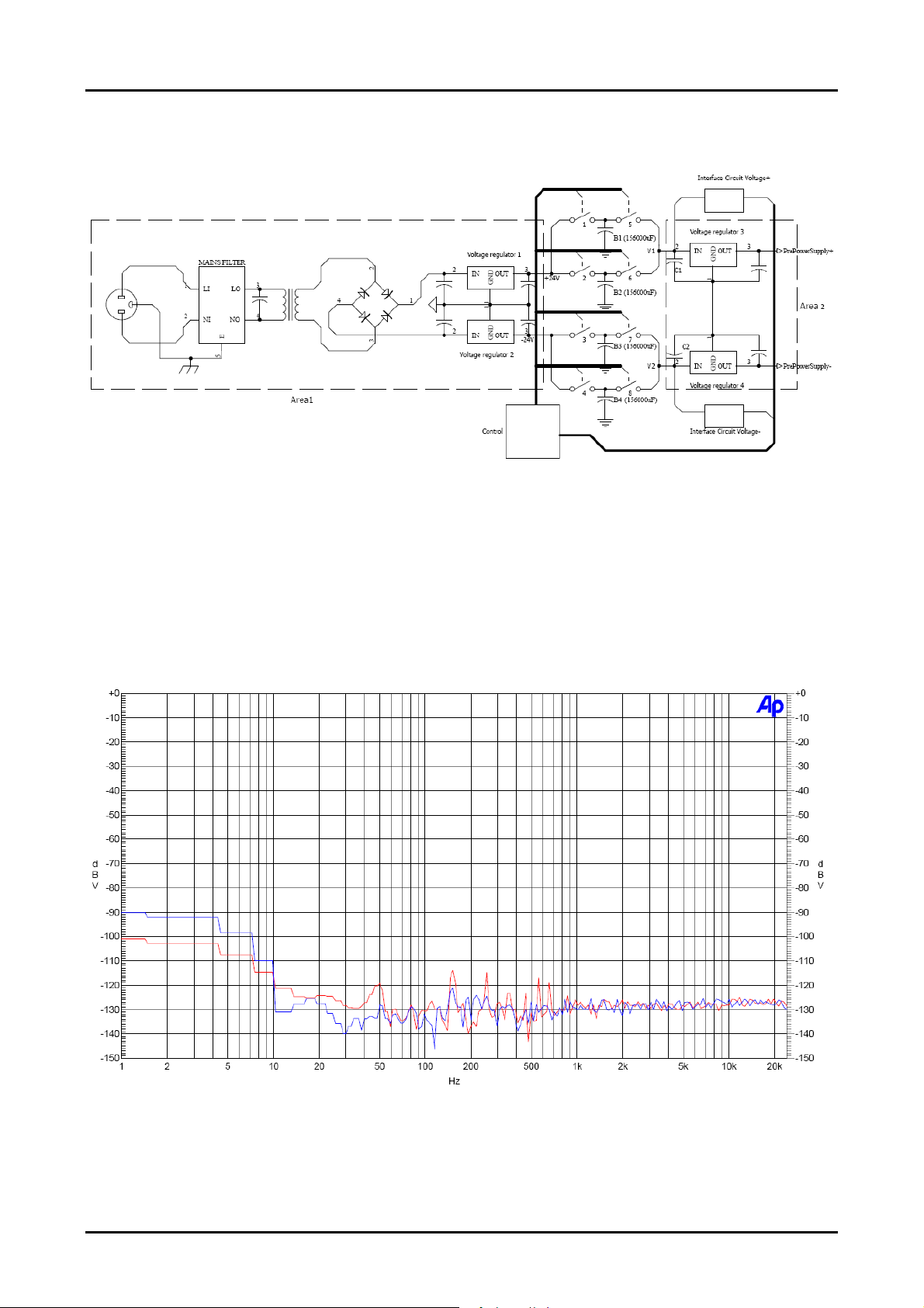
How can you see in the schematic, the AC main is filtered just as it reaches the board
to eliminate any high frequency disturbs. Then the AC voltage is reduced by the
transformer to be used on the board, rectified by the bridge and then filtered. Then
we found two voltage regulators one for the positive voltage and the other for the
negative. The Area1 is “contaminated” by the 50Hz (60Hz) presence. What we have
done in this part is trying to eliminate the interference as more as possible, designing
two discrete components voltage regulators (voltage regulators 1 and 2) with very
high 50Hz/60HZ noise rejection. Until now nothing new under the sun, because these
solutions are present with better or worse results in every good preamplifier, the
virtual battery comes beyond. What we want to do is to never connect in any way the
preamplifier power supply stage (that supplies the preamplifiers, the input selection
circuit and the volume circuit) to the 50Hz/60Hz area.
This is implemented supplying the Voltage regulators 3 and 4 by a capacitor bank of
156000µF(!!!!).
The circuit worsk as follows:
• at the turn on the control, that governs every switches and can sense the
values of the voltage at the points V1 and V2, opens the switches 5, 6, 7 and 8
leaving the Voltage regulators 3 and 4 (and so all the preamp circuits)
unpowered, while closing the switches 1, 2, 3, and 4. In such way after a delay
all the capacitors in the four banks are charged.
• Then the control open the switches 1 and 3 and closes the switches 5 and 7.So
the Area2 is powered by the banks B1 and B3 but is disconnected from Area1.
The voltage regulators 3 and 4 works consuming the charge stored in the
capacitors of the banks B1 and B3. So the voltage at point V1 and V2 decrease.
• The control observes the voltage V1 and V2, and when they are too low the
control switches off the switches 5 and 7 disconnecting the banks B1 and B3
from the Area2, switches off the switches 2 and 4 disconnecting the banks B2
and B4 from the Area1 and then switches on the switches: 6, 8 (connecting
banks B2 and B4 to voltage regulators 3 and 4). Then the control close the
switches 1 and 3 connecting the banks B1 and B3 to the Voltage regulators 1
and 2 and charging again the capacitors of the two banks.
During the switching time the voltage at the input of Voltage regulator 1 and 2 is
supplied by the capacitor C1 and C2.
Bellini preamplifier – Virtual Battery off line power supply 3 / 5
AUDIO FUTURA
AUDIO FUTURA
AUDIO FUTURAAUDIO FUTURA
spa
Of course the story goes on cycle by cycle setting the appropriate voltage at the input
of Voltage regulators 3 and 4.
Fig. 1 - Schematic
The virtual battery works supplying all the preamplifiers circuits separately from the
50Hz/60Hz area eliminating in such way the 50Hz/60Hz interference. The high
frequency interferences are stopped by the AC filter and also reduced by the virtual
battery.
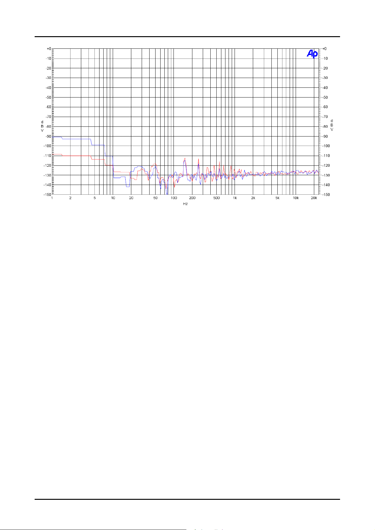
In the measurements beyond we can see the noise spectrum measured at the RCA
output of the Bellini Virtual Battery Preamplifier with no signal applied. Its scale of the
frequency axis is logarithmic to evidence the low frequencies range.
FFT Spectrum Analysis at Volume 0
Bellini preamplifier – Virtual Battery off line power supply 4 / 5
AUDIO FUTURA
AUDIO FUTURA
AUDIO FUTURAAUDIO FUTURA
As you can see in the graphics the 50Hz component have been reduced to -120dB.
Probably that value is due much more to the influence the cables (a standard RCA
ones) get fron the environment. So we can expect the preamplifier to have an even
lower 50Hz component.
spa
FFT Spectrum Analysis at Volume maximum
Bellini preamplifier – Virtual Battery off line power supply 5 / 5
 Loading...