

Page 1

®
Doorbell Module
DBM21
For Whole-House Entertainment System
JULY 2008
SOFTWARE PROGRAMMING
AND
HARDWARE CONNECTION GUIDE
Page 2

- 2 -
Table of Contents
Features ................................................................................................................................................................. 2
Included Accessories........................................................................................................................................... 2
W.H.E.N.™ Minimum System Requirements ...................................................................................................... 3
Identifying Installed Firmware ..................................................................................................................... 3
Detailed Wiring Connection Diagram............................................................................................................... 4
Hardware Connection and Configuration....................................................................................................... 4
Door ID Configuration Switch ..................................................................................................................... 4
DBM21 Connection to W.H.E.N. System .................................................................................................... 4
DBM21 Connection to Door-Phone Directly (Without Complete Phone System)............................... 4
DBM21 Connection to Door-Phone System.............................................................................................. 5
Door-Phone Camera Connection to W.H.E.N. System ........................................................................... 5
AVR21EN Setup ..................................................................................................................................................... 5
Assign Doors and Cameras......................................................................................................................... 5
Name Doors .................................................................................................................................................. 5
Door Ring ....................................................................................................................................................... 5
Door Answer.................................................................................................................................................. 5
Door Open..................................................................................................................................................... 5
Custom Doorbell Chime...................................................................................................................................... 6
Features
• Provides doorbell chimes for the W.H.E.N. system
• Allows two-way communication to a Panasonic compatible door phone station with or without a
Panasonic phone system
• Compatible with Channel Vision™ DP Series door stations including video from built-in cameras
• Allows any custom chime to be programmed (ring tones)
• Each AVH21 supports two DBM21
• Half size allows two units to be mounted side by side in a Leviton or a Channel Vision structured
wiring panels
• Supplies power to door station and door-station camera (if needed) over a single RJ-11
connection
Included Accessories
• 2 WECO, screw-down Phoenix Connectors (Power In and Power Out),
• 6 plastic overlays to select HUB/Door
• 4 Mounting hardware (RICHCO snap in rivets), which are the same pieces used in AVH21 and
WPS21 for mounting to Leviton and Channel Vision structured wiring panels
DBM21 Installation and Instruction Guide - 2 -
Page 3

- 3 -
W.H.E.N.™ Minimum System Requirements
The DBM21 doorbell module requires that the system have the following software as a minimum.
Before installing the DBM21, it will be necessary to check the currently installed firmware of all your
components. If you need to update the firmware it will be necessary to contact Audioaccess
Technical Support at 888.691.4171 (USA only) or 516.496.3400 (Outside USA) or through email at
websupport@harman.com.
Component Firmware Version Found In
AVR21EN AVR MAIN MC Version 2.57 or later AVR21EN Diagnostics
AVR21EN AVR BUS MC Version 3.24 or later AVR21EN Diagnostics
KP21 KP MSP Version 3.18 or later KP21 Settings
Identifying Installed Firmware
Identifying the AVR21EN Main CPU version
To verify the AVR21EN main CPU version, turn ON the avr and go to
the OSD menu under Diagnostics >Settings page 1, version can be
read under AVR MAIN MC. In this example, main CPU version is 2.57.
Identifying the AVR1394 BUS version
To verify the AVR1394 version, turn the AVR on and go to the OSD
menu under Diagnostics > Settings Page 1, version can be read under
AVR BUS MC. In this example AVR1394 Bus version is 3.24.
Identifying the KP21 Firmware Version
The KP21 firmware version is displayed on the keypad display and not in
the receiver’s on screen menu. On the KP21, go to SETUP, press the right
arrow on the keypad four times, press SETTINGS, the display will show
MSP, ICEM and ID for that particular keypad. In this example the KP21
version is 1.22.
DBM21 Installation and Instruction Guide - 3 -
Page 4
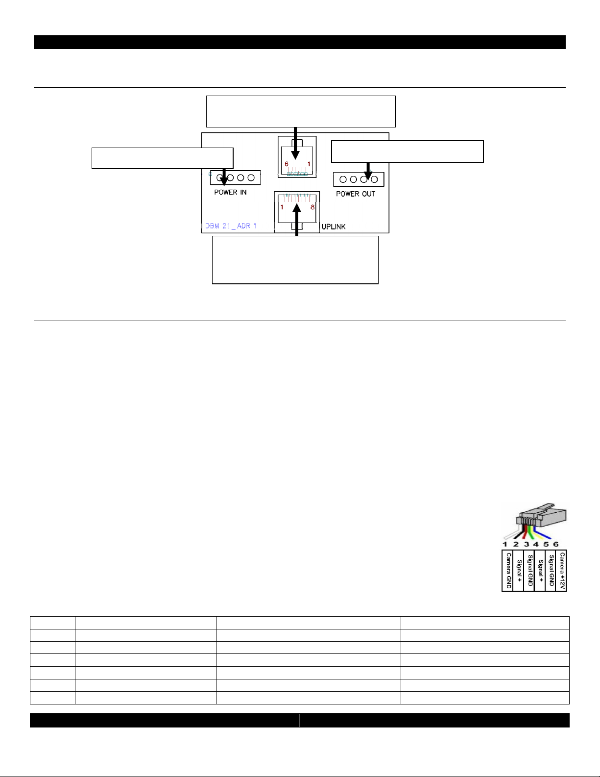
Detailed Wiring Connection Diagram
Power In from AVH21
(
Key
pad communicatio
n bus)
Connection to door-phone station
Uplink to AVH21
RJ-45
Hardware Connection and Configuration
- 4 -
Power Out to next DBM21
Door ID Configuration Switch
Two 2-position switches determine the door number as identified on the appropriate status panel label. The
individual labels are screened and “keyed” to match the two-position switch that sets the door number. There
are six keyed overlays for each combination of Door 1 and Door 2 options connected to up to three (3) AVH21.
The system allows a maximum of six doors, two per AVH21.
DBM21 Connection to W.H.E.N. System
The DBM21 needs to have two connections to the system, similar to a KP21. Power is supplied to the first DBM21
(if there are more then one) from the WPS21 using up to a maximum14 gauge, 4 conductor, unshielded wire,
and a minimum 16-gauge, 2-conductor unshielded wire. This supplies 24v DC power to the DBM21. Multiple
DBM21 can be daisy chained for power. The second connection will use a standard CAT5e cable with RJ45
termination as is used in standard Ethernet connections. Note, these are not Ethernet connections and cannot
be connected to an internet port. Connect the each DBM21 to an open keypad connection on the AVH21. The
DBM21 takes the place of one of the active zones in the system.
DBM21 Connection to Door-Phone Directly (Without Complete Phone
System)
Using CAT3, CAT4 or CAT5 wire, terminate the RJ-25 (RJ-11 with 6 conductors) connection
according to the diagram shown here and the chart below. Refer to the door phone
instructions for proper connections at the door phone.
DBM21 Door Panel output, RJ11
Pin # Description Connect To: Note
1 Camera power Ground Door-Station Camera Power Ground Optional Camera
2 Door-Panel Signal Out Phone Signal + internally Connected to Pin 4
3 Door-Panel Ground Phone Signal Ground Internally Connected to Pin 5
4 Door-Panel Signal Out Phone Signal + Internally Connected to Pin 2
5 Door-Panel Ground Phone Signal Ground Internally Connected to Pin 3
6 Camera Power 12 Volt DC Door-Station Camera Power DC + Optional Camera
DBM21 Installation and Instruction Guide - 4 -
Page 5

- 5 -
DBM21 Connection to Door-Phone System
Terminate the RJ-25 (RJ-11 6 conductor) connection as in the chart above on both ends.
Connect the DBM 21 to a standard 3-way phone splitter. Connect the door-phone station,
the Panasonic phone system and the DBM21 to the splitter.
Door-Phone Camera Connection to W.H.E.N. System
The camera can be located inside the door-phone station (optional on Panasonic and Channel Vision models)
or can be a standard security camera located near the front door. The DBM21 will supply power for the internal
camera in the door station (if equipped). Using standard coaxial (RG-6 or RG-59) cables connect the output of
the camera to an input on the AVH21. In the AVR21EN camera setup, be sure to assign the camera input used
to the appropriate DBM21.
AVR21EN Setup
Please see the AVR21EN installation manual for details. The AVR21EN can control how the doorbell chimes are
played through each zone, how the zones can interact with the door-phone station and if a security camera is
associated with a door-phone station.
Assign Doors and Cameras
To access the door setup go to the on-screen menu of the AVR21EN. From the main menu, select Zone Setup,
and then select Assign Services. From the Assign Services menu select the Door Setup menu. Select the doors
that are in use and the cameras (if any) assigned to them.
Name Doors
From Zone Setup Page 1, select Name Doors. All doors in the system can be renamed.
Door Ring
From Zone Setup Page 2, select Setup By Number Page 2 and enable or disable door bell chimes for each
zone. The default is for all zones to ring always.
Door Answer
From Zone Setup Page 2, select Setup By Number page 2 and enable or disable door bell answer for each
zone. This will allow or block specific keypads from talking to the door station. The default is for all zones to
answer all doors.
Door Open
From Zone Setup page 2, select Setup By Number page 3 and enable or disable door bell open for each zone.
This will allow or block specific keypads from opening the door locks if the system is using the electronic door
locks on the AVH21. The default is for all zones to open all doors.
DBM21 Installation and Instruction Guide - 5 -
Page 6

- 6 -
Custom Doorbell Chime
Using Wave Pad Sound Editor (freeware which can be downloaded from
http://nch.com.au/wavepad/index.html), create desired doorbell sound file. The doorbell sound starts
approximately 0.5 seconds after the door button is pushed, so insert a 0.5 second silence at the beginning of
sound. Save file as: Dialogic vox file; 32000K sample rate; mono.
After file is saved change extension from “.vox” to “.bin”. For example: “sound.vox” to “sound.bin”. Use this file
with W.H.E.N. Multi-Room Components Software Upgrade (HK Upgrader.exe). This software package can be
requested from Audioaccess Technical Support at 888.691.4171 (U.S.A. Only), or by email at
websupport@harman.com. Sound files can be loaded to all six DBM21 at once or to each DBM21 individually.
Upgrade procedure is the same as Keypad or A/V Hub upgrade; details are included with the upgrade
software when received from Technical Support.
DBM21 Installation and Instruction Guide - 6 -
Page 7

- 7 -
DBM21 Installation and Instruction Guide - 7 -
Page 8

- 8 -
Harman Consumer Group
250 Crossways Park Drive
Woodbury, NY 11797
www.audioaccess.com
www.support.audioaccess.com
E-mail: Websupport@harman.com
516.496.3400
888.691.4171 (U.S.A. Only)
FAX: 516.682.3510
©2008 Harman International Industries, Incorporated. All rights reserved.
Audioaccess is a registered trade mark of Harman International Industries, Incorporated.
W.H.E.N. (Whole-House Entertainment Network) is a trademark of Harman International Industries,
Incorporated
Channel Vision is a trademark of Channel Vision Technologies
DBM21 Installation and Instruction Guide - 8 -
 Loading...