

Page 1
Operating Instructions
IR-Satellite Infrared Sensor/Receiver
Model No.
TLD100
Before attempting to connect or operate this product,
please read these instructions carefully and save this manual for future use.
The model number is abbreviated in some descriptions in this manual.
Page 2

WARNING:
• The main plug or an appliance coupler shall remain
readily operable.
• To prevent injury, this apparatus must be securely
attached to the floor/wall/ceiling in accordance with the
installation instructions.
• The connections should comply with local electrical
code.
CAUTION:
• Before attempting to connect or operate this product,
please read the label on the back.
This Class A digital apparatus complies with Canadian
ICES-003.
Cet appareil numéique de la classe A est conforme la
norme NMB-003 du Canada.
NOTE: This equipment has been tested and found to
comply with the limits for a Class A digital device,
pursuant to Part 15 of the FCC Rules. These limits are
designed to provide reasonable protection against
harmful interference when the equipment is operated in
a commercial environment. This equipment generates,
uses, and can radiate radio frequency energy and, if not
installed and used in accordance with the instruction
manual, may cause harmful interference to radio
communications. Operation of this equipment in a
residential area is likely to cause harmful interference in
which case the user will be required to correct the
interference at his own expense.
FCC Caution: To assure continued compliance, any
changes or modifications not expressly approved by the
party responsible for compliance could void the user’s
authority to operate this equipment. For example, use
only shielded interface cables when connecting to
computer or peripheral devices.
The model number and serial number of this product
may be found on the surface of the unit.
You should note the model number and serial number of
this unit in the space provided and retain this book as a
permanent record of your purchase to aid identification
in the event of theft.
For Canada
For U.S.A
For U.S.A.
2
Model No.
Serial No.
Page 3

Important safety instructions
1) Read these instructions.
2) Keep these instructions.
3) Heed all warnings.
4) Follow all instructions.
5) Do not use this apparatus near water.
6) Clean only with dry cloth.
7) Do not install near any heat sources such as radiators, heat registers, stoves, or other apparatus (including amplifiers)
that produce heat.
8) Protect the power cord from being walked on or pinched, particularly at plugs, electrical outlets, and the point where
they exit from the apparatus.
9) Only use attachments/accessories specified by the manufacturer.
10) Use only with the cart, stand, tripod, bracket, or table specified by the manufacturer, or sold with the apparatus. When
a cart is used, use caution when moving the cart/apparatus combination to avoid injury from tip-over.
S3125A
11) Unplug this apparatus during lightning/electrical storms or when unused for long periods of time.
12) Refer all servicing to qualified service personnel. Servicing is required when the apparatus has been damaged in any
way, such as power-supply cord or plug is damaged, liquid has been spilled or objects have fallen into the apparatus,
the apparatus has been exposed to rain or moisture, does not operate normally, or has been dropped.
3
Page 4

Limitation of liability
THIS PUBLICATION IS PROVIDED “AS IS” WITHOUT WARRANTY OF ANY KIND, EITHER EXPRESS OR IMPLIED,
INCLUDING BUT NOT LIMITED TO, THE IMPLIED WARRANTIES OF MERCHANTABILITY, FITNESS FOR ANY
PARTICULAR PURPOSE, OR NON-INFRINGEMENT OF THE THIRD PARTY’S RIGHT.
THIS PUBLICATION COULD INCLUDE TECHNICAL INACCURACIES OR TYPOGRAPHICAL ERRORS. CHANGES ARE
ADDED TO THE INFORMATION HEREIN, AT ANY TIME, FOR THE IMPROVEMENTS OF THIS PUBLICATION AND/OR
THE CORRESPONDING PRODUCT(S).
Disclaimer of warranty
IN NO EVENT SHALL AUDIO ENHANCEMENT, INC. BE LIABLE TO ANY PARTY OR ANY PERSON, EXCEPT
FOR REPLACEMENT OR REASONABLE MAINTENANCE OF THE PRODUCT, FOR THE CASES, INCLUDING BUT NOT
LIMITED TO BELOW:
(1) ANY DAMAGE AND LOSS, INCLUDING WITHOUT LIMITATION, DIRECT OR INDIRECT, SPECIAL, CONSEQUENTIAL
OR EXEMPLARY, ARISING OUT OF OR RELATING TO THE PRODUCT;
(2) PERSONAL INJURY OR ANY DAMAGE CAUSED BY INAPPROPRIATE USE OR NEGLIGENT OPERATION OF THE
USER;
(3) UNAUTHORIZED DISASSEMBLY, REPAIR OR MODIFICATION OF THE PRODUCT BY THE USER;
(4) ANY PROBLEM, CONSEQUENTIAL INCONVENIENCE, OR LOSS OR DAMAGE, ARISING OUT OF THE SYSTEM
COMBINED BY THE DEVICES OF THIRD PARTY.
Preface
The units described in this installation guide are the models that are compatible as of April 2012. Contact your dealer for
further information.
4
Page 5

Precautions
• Contact your dealer for installation.
Skill and experience are required for installation to
avoid risk of fire, electric shock, injury and damage.
• Do not insert objects.
• If water or metallic items are inserted inside, there
is a risk of fire or electric shock.
Unplug all cables and contact your dealer.
• Do not disassemble and modify.
There is a risk of fire or electric shock.
• Stop using the product immediately if any abnormality
is detected.
There is a risk of fire if you continue to use the product
after smoke or odor is detected.
Unplug all cables and contact your dealer.
• Avoid placing the product in unstable positions to prevent falling or injury.
• Be sure to hold the plug while pulling the power cable.
The cable may be damaged and there is a risk of fire
or electric shock.
• Dust off the power plug of power cable periodically.
If dust accumulates, insulation failure caused by
humidity occurs and there is a risk of fire.
Unplug the power plug and wipe it with a dry cloth.
• Insert the power plug of power cable completely.
There is a risk of electric shock or overheating if the
insertion is incomplete.
Do not use a damaged or loosened plug and AC
outlet.
• Do not use the product beyond the rated value of the
AC outlet or wired devices.
Do not use voltage of more than 100 V AC – 240 V
AC.
Multiple circuit wiring exceeding the rated value may
result in overheating and fire.
• Do not use the power cable or the AC adaptor in a
way that may cause damage (modifying, placing near
heat, bending excessively, twisting, stretching, weighing down or bundling). There is a risk of electric shock,
short-circuit or fire when using damaged power cable
or AC adaptor. Contact your dealer.
• To avoid electric shock, do not handle the power plug
or power cable with wet hands.
• Avoid placing containers of liquid such as water near
the product.
If liquid spills onto the product, it may cause fire or an
electric shock.
Unplug all cables and contact your dealer.
• Do not install or wire during lightning/electrical storms.
There is a risk of fire or electric shock.
• Fix the mounting screw firmly to prevent falling or
or injury.
Contact your dealer for installation.
• Use the specified Switch-mode power supply (hereinafter, AC adaptor).
There is a risk of electric shock if any unspecified AC
adaptor is used.
Make sure to use the supplied AC adaptor.
• Be sure to turn off the power of this product before
installation.
There is a risk of electric shock.
• Do not place the product in humid or dusty locations.
There is a risk of fire or electric shock.
• Power supply: 100 V AC – 240 V AC. (Using supplied
AC adaptor)
Do not use the same AC outlet with high-powered
products (such as copy machine or air conditioner).
• Operating temperature (including AC adaptor):
0 °C to +40 °C {+32 °F to + 104 °F}.
If the product is used in temperature out of this
range, internal parts may be badly affected, and
malfunctions may occur.
• Condensation:
There is a high risk of condensation when humidity is
high or when the product is transferred from low to
high temperature. When condensation occurs, wait for
around 1-2 hours, and after confirming the condensation has disappeared, turn on power.
• Unplug the power plug of AC adaptor when out of use
for long periods of time.
• Microphone:
Match the channel of the microphone and the product
in use.
Keep the distance of each microphone more than
• Noise:
The noise produced from electrical devices such as a
lighting fixture or plasma display when turned “ON” or
"OFF" may cause loud noise from the product.
Keep the infrared wireless devices and coaxial cables
away from the source of noise (high-powered products
such as copy machine or air conditioner and their
power cables) in order to reduce noise.
• Keep this product away from dripping or splashing
water.
• Avoid placing receptacles that contain liquids, such as
vases, on the product.
•
After discontinuing use of the product, it should be
removed to prevent it from dropping.
50 cm {19-11/16 inches}.
Product care
Unplug the power plug of AC adaptor before cleaning
•
the product, otherwise injuries may result.
Wipe with a dry soft cloth.
•
•
Do not clean with volatile liquids such as benzine
and thinner. When using a chemical cloth for cleaning,
observe the precautions provided with that product.
5
Page 6

CONTENTS
Important safety instructions ................................................................................................................3
Limitation of liability .............................................................................................................................. 4
Disclaimer of warranty .......................................................................................................................... 4
Precautions ..........................................................................................................................................5
Features ................................................................................................................................................6
Caution about interception of transmission ......................................................................................... 7
Caution about external-device control function ................................................................................... 7
Caution about feedback blocker ..........................................................................................................7
Major operating controls and their functions (Sensor) .........................................................................8
Major operating controls and their functions (Conversion box) ........................................................... 9
Operating procedures ........................................................................................................................10
Precautions for installation .................................................................................................................11
Functions and settings .......................................................................................................................13
Connections ....................................................................................................................................... 19
Installation .......................................................................................................................................... 26
Serial communication command ........................................................................................................29
Troubleshooting ..................................................................................................................................33
Specifications .....................................................................................................................................34
Included Components ........................................................................................................................35
Features
This unit is a receiver which integrates both a sensor receiving infrared light from the infrared wireless microphone (MTD-09,
MHH-09) and a receiving component. Integration of a receiving component and a sensor allows an infrared wireless microphone system to be simply constructed by mounting this unit on the ceiling. Use of the supplied conversion box provides
extension between the receiver and an amplifier, and accordingly leads to flexibility in installation locations.
This unit also includes the feedback blocker to decrease feedback generated when the microphone and speaker approach
each other.
• As the unit uses infrared light, it is not affected by interference from adjacent rooms.
• The microphone is available as a handheld model (MHH-09) and as a pendant “teardrop” model (MTD-09). The
2-channel microphone of this unit and the audio level of the line can be controlled with the pendant type.
6
Page 7

Caution about interception of transmission
This product is a wireless system using infrared, and the transmission and reception of audio signals are possible within
the range that the infrared light can reach.
If any third party is within the range of the infrared, the audio signals can reach anywhere unless there are obstacles (such
as walls). Therefore, if there is no action taken to prevent interception, malicious third parties may listen to content by intercepting the infrared intentionally.
In order to handle this problem, you may set up infrared shielding materials such as shade curtains to close the transmitting and receiving range to reduce the interception.
We would like you to fully understand the risks of using this product without taking precautions for interception, and we
recommend you take your own preventative measures.
If interception occurs due to negligence or the specifications of the infrared wireless, we shall not take any responsibility for
the damages that are caused thereby.
Caution about external-device control function
This product is not intended for a security application.
Never use the external-device control function of the product for security use.
We shall not take any responsibility for damages resulting from troubles or malfunction due to cable disconnection.
Caution about feedback blocker
The feedback blocker, with which this product is equipped, is not intended to suppress the feedback howling completely.
A sudden large noise may be produced even when the feedback blocker is activated.
When installing speakers and a sensor, make sure that the feedback howling is not produced.
7
Page 8
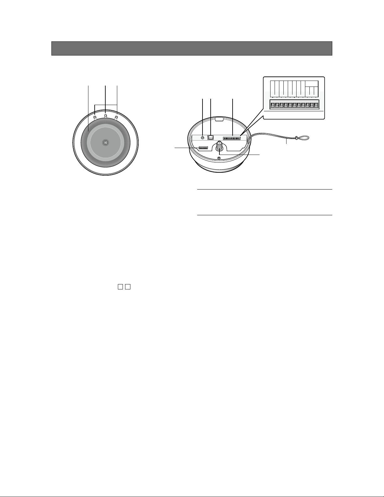
Major operating controls and their functions (IR-Satellite or Sensor)
Front Back
GND
F2 ACK
F2 COM
F2 CNT
F1 COM
③②①
④ ⑤ ⑥
F1 CNT
GND
PAGE MUTE
RS-232C
TxD
RxD
SG
⑨
Infrared sensor cover
①
To receive only the infrared by the inner sensor, the
visible light is filtered out by this infrared sensor cover.
Operation indicator [OPERATE]
②
(Green/Yellow/Red)
This LED lights green when the power is on and this
unit is receivable under normal conditions.
This LED lights as follows to indicate other states:
F2 signal output provided: red light
Page mute signal received: yellow light
See page 16 for further information on operation.
③ Reception indicator [ / ]
21
This LED lights green when this unit is receiving sig-
nals from each microphone under normal conditions.
This LED lights as follows to indicate other states:
F1 or F2 signal output provided: red light
Page mute signal received: yellow light
Feedback blocker in operation: yellow light
See page 16 for further information on operation.
④ LINE IN connector [LINE IN L/R]
This connector is used to provide an audio input from
external sources such as a projector or CD. This is a
stereo, line level input, and is internally mixed to a
monaural signal.
A stereo mini plug (ø3.5 mm) is used.
⑤ Conversion box connector
[TO CONVERSION BOX]
This connector is used to connect the cable to the
supplied conversion box.
A standard CAT5 or CAT5e cable is used to connect
to the conversion box.
⑦
⑧
CAUTION:
• DO NOT connect this device to any type of Ethernet
(LAN) system.
⑥ Control (Auxillary) terminals
An 11-pin Euro block is used.
The following terminals are equipped.
F1 CNT: provides F1 signal* output controlled by
MTD-09.
F2 CNT: provides F2 signal* output controlled by
MTD-09.
* These are available when MTD-09 is used.
Settings of F1 and F2 are performed with
MTD-09.
F2 ACK: used to activate F2 ACK LED signal.
PAGE MUTE: provides signal inputs externally
when the paging function is used.
RS-232C: is used to control this unit via communica-
tion from an external device.
⑦ Safety strap
This strap is attached to the ceiling mount bracket and
prevents the sensor/receiver from dropping.
⑧ Extension sensor input connector
[EXT SENSOR]
This connector is used for sensor extension. A single
additional sensor (EDS-07) can be connected
directly to this connector. A total of 4 sensors can be
connected to this terminal with the additional coupler
(AE-DCF).
8
Page 9
⑨ DIP Switch
This switch can select the operation mode of each
function equipped in this unit (see page 17).
The settings of this switch are updated at the time of
turning on the power. Settings changed while powered
up are not updated until the power is turned off and
then back on (excluding DIP Switches No. 7 and 8).
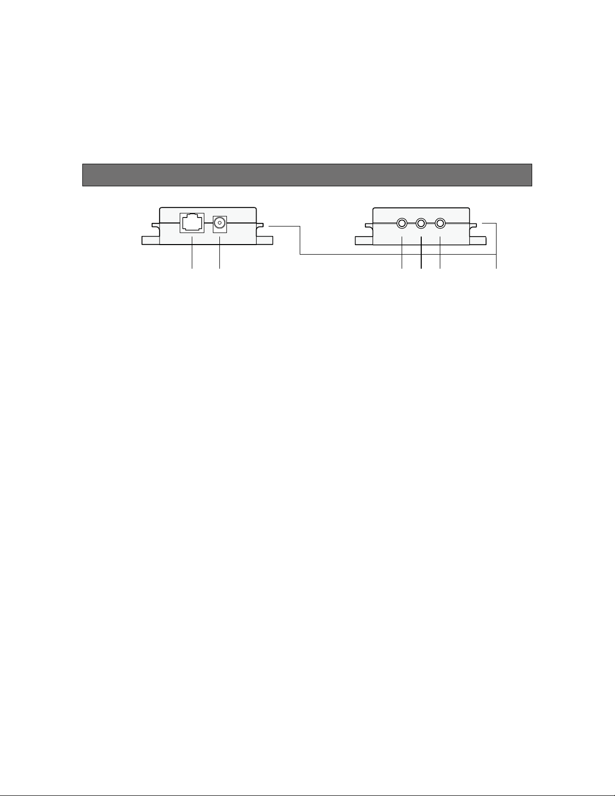
Major operating controls and their functions (Conversion box)
① ② ③ ④ ⑤ ⑥
① Receiver connector [TO RECEIVER]
This connector, labeled “TO RECEIVER”, is used to
connect a cable to the sensor/receiver.
② DC power connector [DC IN]
This connector is used to connect the supplied AC
adaptor. No switch is equipped in this unit. This unit
operates immediately after connecting the AC adaptor
to this connector.
③ Microphone CH1 output connector [CH1]
This connector provides the audio output of
microphone CH1 received by this unit. This is
a TRS balanced output.
④ Microphone CH2 output connector [CH2]
This connector provides the audio output of
microphone CH2 received by this unit. This is
a TRS balanced output.
⑤ Mixing output connector [MIX OUT]
This connector provides the audio output of LINE IN of
the main unit. Setting the No. 4 of the DIP switch to
ON allows the audio outputs of the microphone CH1
and CH2 received by this unit to be provided after
mixing with LINE IN.
Tip (+), Ring (-), Sleeve (ground).
⑥ Cable binding hook
This hook is used to hold cables with a cable tying
band or the like.
This is a TRS balanced output:
9
Page 10
Operating procedures
F
S
E
L
E
C
T
O
W
N
O
T
H
E
R
L
I
N
E
M
U
T
E
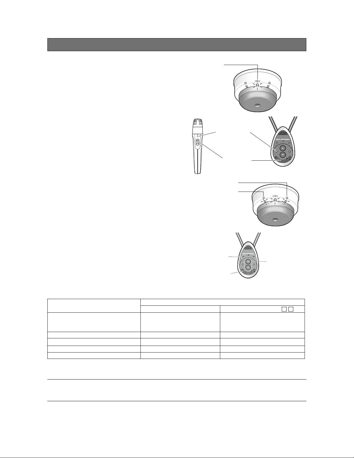
1 Insert the plug of the supplied AC adaptor into
the wall outlet.
The operation LED of the sensor/receiver lights green.
2 Turn on the power switch of the microphone.
(MTD-09, MHH-09)
The reception LED indicator of the sensor/receiver
lights green depending on a channel to be received.
3 Adjust the volume of external devices such as
an amplifier.
The overall volume is adjusted with an amplifier or
another external device. Use of the volume button of
MTD-09 allows the volume of itself to be adjusted. In
addition, selection of the target with the selection
button of the MTD-09 allows the volume of the other
microphone received by this unit and the volume of
LINE IN of this unit to be adjusted.
Operation indicator
Power indicator
ON
MHH-09 MTD-09
Microphone CH2
Microphone CH1
Power switch
TLD100
BATT
TLD100
CHG
PWR
H
E
T
R
O
L
N
I
N
W
4 The LED of the sensor/receiver indicates the
operating state of this unit during operation.
Refer to page 16 for further information.
Selection indicator
Selection button
E
O
BATT
S
E
L
E
M
U
E
T
C
T
PWR
CHG
F
Volume buttons
MTD-09
LED of sensor/receiver
Operation indicator
Reception indicator /
F2 signal output provided* Red light Red light
(Green light at F2 ACK input
provided)
F1 signal output provided* Green light Red light (for 300 ms)
Page mute signal input provided Yellow light Yellow light
Microphone volume operated* Green light No light (for 300 ms)
Feedback blocker operated Green light Yellow light (for 5 s)
* Applicable when MTD-09 is used
Note:
• Read the operating instructions of the microphones (MTD-09, MHH-09) as well.
• The volume adjusted with the volume button of the microphone retains its level even if the power is turned off.
21
10
Page 11

Precautions for installation
The installation should be carried out following local standards for electric products.
Warning
• Be sure to contact your dealer for installation.
Before installing, turn off the power of the connecting product. In addition, be sure to read "Precautions" carefully and
follow the instructions. Moreover, be sure to read operating instructions of the connecting product as well.
• Power
Connect the power plug of the AC adaptor by using a circuit breaker in any of the following ways:
Install this product near the power outlet.
Connect this product with the breaker of a distribution board which has a contact point of not less than 3.0 mm
{3/32 inches}.
Use a breaker that can block all the poles except for protective earth conductors.
Connect this product via the outlets of devices that can block power such as a power control unit.
• Static Electricity
Discharge any static electricity charged in your body by touching a metallic area before installing in order to prevent
damage caused by static electricity.
• Install the infrared sensor within a range that the microphone can reach and in a location that can be
seen in moving range.
• Be sure the connector and coaxial cable are connected in the correct way.
If the process and connection are incomplete, receiving sensitivity may be reduced and product will be more easily
affected by external noises.
• Do not install in locations where strong light or sunlight strikes the infrared sensor directly.
If the product is installed near a window, the product is subject to the solar light even if the solar light does not strike
it directly, which may reduce the receiving sensitivity and shorten the range. Install the product as far from strong light
as possible (more than 5 m {16 feet}). If the situation is still not improved, it may be better to install it farther from
window side or use a curtain or window shade.
• Avoid installing near a warm air flow path. In addition, if the product is installed in locations with an
abundance of moisture, dust or vibration, there is a risk of damage.
• In locations with a large amount of dust, the dust may accumulate on the Infrared Sensor Cover, which
may interfere with reception of the infrared signal. As a result, the range may be reduced. Therefore,
avoid installing in locations with a lot of dust.
• Do not install and use in following locations:
① Locations directly affected by rain or water (including spaces under the eaves).
② Locations such as a pool where medical agents are used.
③ Locations such as a kitchen or factory workshop where there is a lot of vapor or oil and special environments such
as in flammable atmospheres.
④ Locations where radiation or X-rays and strong electric fields or magnetism arise.
⑤ At sea or along the coast, and locations such as hot springs where corrosive gases arise.
⑥ Locations with a lot of vibrations caused by large vehicles or ships (this is not a product for vehicles).
⑦ Locations where water drops made by condensation will splash.
11
Page 12

• Plasma television screens generate infrared interference. It is not recommended to use a plasma
display in the same room where the TLD100 is installed.
However, if a plasma screen must be used, install it in the following way and after confirming
operation, use it very carefully.
① Install the infrared sensor in a location where side and back of plasma display cannot be seen, and install it as far
away as possible (more than 10 m {33 feet}).
② The distance between the infrared sensor and microphone should be as short as possible (within 3 m {10 feet})
while in use.
③
Do not put any blocks (including the human body) between the infrared sensor and microphone while in use.
Even after following these recommendations, interference may still occur.
④
• The distance between a fluorescent lamp and the infrared sensor should be as far apart as possible
(more than 1 m {3.3 feet}) in installing.
• If a remote controller such as an audio-visual device or air conditioner is controlled by an infrared
sensor, noise or sound breaks may occur.
• If there are any other devices making strong noises, product may sometimes be impossible to use.
In that case, install the product farther away until it can be used.
• Ceiling height is expected to be 2 m {7 feet} to 4 m {13 feet}. If it is out of this range, the arrival range
may be shortened.
• The base color of wall, floor, and ceiling should be white or light colors. With black or dark color
surfaces, the arrival range may be shortened.
• A reflection from the wall is used in the arrival range. If the wall is far away from the area of use, the
arrival range may be shortened.
• Sound breaks may occur near windows or in rooms with a lot of windows. In this case, it may be
useful to use light-colored curtains or window shades.
• If a microphone is used near and facing a wall, sound breaks may occur.
• For tightening bolts and screws, pay attention to the following points:
① Torque control is necessary for tightening the bolts and screws.
② Torque wrench and torque driver are necessary for controlling the torque.
③ Never use any impact driver or electric drill because torque control is difficult even if they have a clutch. Their use
may result in damage to the mounting part.
• After mounting, confirm visually that the product is firmly and stably fixed. If the product is properly
installed, it will not wobble or make noise.
• In installing this infrared sensor, be aware of the following:
① Be sure that the installation is carried out by qualified personnel when installing at high locations.
② Before installation, confirm that there is nobody around.
③ In order to carry out the installation safely and surely, pay close attention to the safety control.
• The supplied safety strap shall be used.
Be sure to firmly secure the safety strap to the ceiling mount bracket at installation.
• Precaution for installation place and securing of the conversion box:
The conversion box shall be installed on a stable place such as on a shelf and secured with screws as necessary.
• Do not apply strong force to this unit. Failure to observe this may damage this unit.
12
Page 13

Functions and settings
Functions
Microphone override function
•
This is a function where the audio level of LINE IN is automatically adjusted to lower when the audio input of the
microphone CH1 or microphone CH2 is provided. The
attenuation of the audio level is –12 dB.
When the audio input of microphone 1 or microphone
2 is no longer provided, the volume of LINE IN automatically
returns to the original level.
Paging mute function
•
This is a function where the audio outputs of microphone
CH1, microphone CH2, and mixing output of this unit are
muted by closing the PAGE MUTE terminal.
This function is specified with the DIP switch. This function is
set to OFF at default settings.
Level
Microphone
CH1/CH2
LINE IN
= 12 dB
Time
Page mute
Level
Microphone CH1/CH2, LINE IN
Mute
Tone function
•
This is a function where the annunciator tone is provided from the MIX OUT connector when the volume button is
operated with the optional microphone, MTD-09. This tone is generated twice at the end of the up or down range.
The level of the operation sound can be selected to HIGH or LOW with the DIP switch. The level is set to LOW at
default settings.
This function can be turned on or off with the DIP switch. This function is set to OFF at default settings.
Microphone/line mixing function
•
This function is designed to assign microphones CH1 and CH2 to the mixing out, and the three signals (mic 1, mic 2
and line) will be mixed by the mixing out on the DIP switch. No mixing is provided at default settings.
Remote volume function
•
The volume of this unit cannot be adjusted with the volume button of the optional microphone, MTD-09.
The volume of external devices can be adjusted with the communication control function of this unit, using the
DIP switch.
The volume of the external devices can be controlled with the microphone on this unit’s default settings.
Mixing output attenuator function
•
Setting the mixing output attenuator to ON reduces the mix output level by 10 dB.
This function is useful when a device with high input sensitivity is connected.
This function is specified with the DIP switch. The output is set to –10 dB at default settings.
Time
13
Page 14

About the feedback blocker
This is a function when a feedback loop is generated as the microphone is used in close proximity to a speaker.
An integrated filter is automatically selected according to the generated audio frequency, and reduces the uncomfortable
feedback loop.
This function is specified with the DIP switch. This function is set to OFF at default settings.
Note:
• This function is simplified and cannot fully remove the feedback loop. When the feedback loop is extremely large, this
function will work to mute all the audio outputs of this unit.
14
Page 15

F1 CNT, F2 CNT function
These functions are available when MTD-09 is used. When F1 or F2 signal is transmitted from the microphone, it will
active F1 CNT or F2 CNT terminal on the receiver. Selection between F1 and F2 is made at the microphone side.
Function 1 (F1): Default setting is Open.
Press the function button [F] of the microphone to select the closed state of 300 ms.
Function 2 (F2): Default setting is Open.
Press the function button [F] of the microphone for 2 seconds or more to select the closed state.
Note:
• To stop the microphone from transmitting the F2 signal, it must be turned off. Then turn off the IR-Satellite Sensor/
Receiver (this unit) to reset it.
If the IR-Satellite Sensor/Receiver (this unit) is not turned off, the F2 terminal will be open (reset) 3 minutes after not
receiving a signal from the microphone.
Type Actions
F1 CNT
(Press)
F1 CNT
(Holding
down)
F2 CNT
Microphone
100
TLD
F1
terminal
Microphone
TLD100
F1
terminal
Microphone
Closed
Open
Closed
Open
F1
3 LEDs flash
in blue.
Default setting:
Open
F1
3 LEDs flash
in blue.
Default setting:
Open
F2
ON
Flash!
Flash!
300 ms
Flash!
300 ms 300 ms 300 ms
3 LEDs
light
in blue.
Flash!
Holding down
2 s 1 s 1 s 1 s 1 s
Flash! Flash!
600 ms600 ms600 ms
Commands are sent
periodically from the
microphone until the
power is turned off.
Commands are
sent periodically
from the
microphone while
holding down the
function button
[F].
300 ms
OFF
or
Hidden
TLD100
F2
terminal
Closed
Open
F2 terminal will be closed when
3 commands are sent within 5
seconds after the first F2
command.
Default setting:
Open
1st 2nd 3rd
5 s timer/ch
Last F2 command
3 minutes from the
last F2 command
3 minutes timer
Timer restarts.
15
Page 16

F2 ACK function
•
When an F2 ACK signal is received, the reception LED indicator of this unit (CH1 or CH2) turns from red to green.
When, after turning the microphone off and on again, the F2 signal has not been received for three minutes, the operation
LED turns from red to green to indicate the normal operating state.
LED lighting indication (Status-at-a-glance)
•
The three LEDs of this unit act as operation indicators and will change color based on the operating state (see tables below).
Furthermore, the priority order of indications is dependent on operating states.
Indication
priority
1
(highest)
2
3
4
5
6
(lowest)
*1 F1 and F2 signal outputs and operating the volume button are available only with the microphone, MTD-09.
*2 The indicator lights green again 3 minutes after the F2 signal is turned off with the microphone, MTD-09 (see page 15).
Note:
• The LED indication indicates the state of the operation with the highest priority among operations of this unit.
After the indication of the operating state with the higher priority ends, the operating state with the next higher priority
is indicated, and this pattern is repeated in this manner.
Operating state LED indication
CH1 Operate CH2
F2 signal output provided*
Paging mute signal input Yellow Yellow Yellow
F1 signal output provided*
Microphone volume button
operated*
Feedback blocker operated Yellow Green Yellow
Microphone in reception or
this unit in operation
1
1
Green light at F2 ACK
1
No lighting for 300 ms at
operating volume button
Lighting at receiving with
Red Red*
input provided
Red Green Red
Lighting for 300 ms Lighting for 300 ms
No lighting Green No lighting
Lighting for 5 s Lighting for 5 s
Green Green Green
This unit in operation Lighting at receiving
microphone CH1
2
Green light at F2 ACK
No lighting for 300 ms
with microphone CH2
Red
input provided
at operating volume
button
16
Page 17

DIP switch setting
•
* Default setting
In this illustration, the side with
each switch number is OFF.
No Name Function On Off
1 Microphone Override Selection of microphone override function Activated* Deactivated
2 Tone ON/OFF Selection of tone signal from this unit at
operating volume button of MTD-09
3 Tone Level High/Low Selection of tone signal (2 levels) at operating
volume button
4 Microphone/Line Mixing Selection of whether to mix the microphones
CH1 and CH2 to the mixing output (Line Out)
5 Feedback Blocker setting Selection of feedback blocker function Feedback blocker
6 Remote Volume setting Selection of remote volume function, normal
mic buttons or reassigned.
When this switch is set to ON, the volume
control of this unit using the volume button of
MTD-09 will be deactivated.
This setting is intended for the control of an
external device using the volume button of
MTD-09 through the serial communication
command. (Page 29)
7 Mix Out Attenuator setting Attenuation of audio output of the mixing
output (–10 dB)
8 Ext Sensor Set to ON when adding the sensor (EDS-07)
as an extension device by utilizing the
optional Infrared Sensor Coupler (AE-DCF).
Tone ON Tone OFF*
High level Low level*
Mixing activated Mixing
deactivated*
Feedback blocker
activated
Mic buttons
reassigned
ATT effective*
-10dB
When utilizing the
AE-DCF
deactivated*
Mic buttons
normal*
(as labeled)
ATT deactivated
When not utilizing
the AE-DCF*
* Default setting
Note:
• Settings of the DIP switch No. 1 - 6 are recognized when the power of this unit is turned on. Therefore, change of settings after turning on the power does not update the settings of this unit. When settings of the DIP switch are
changed, the power needs to be turned off and on again.
The functions settable with the DIP switch can also be changed through RS-232C (page 29).
In this case, the communication control can change settings even after the power is turned on.
• The internal circuit is physically changed by the DIP switches No. 7 and 8. It is impossible to change the circuit
through RS-232C. Be sure to set these switches manually to ON or OFF.
• Improper setting for the DIP switch No. 8 may shorten the transmission range.
17
Page 18

Channel setting
•
Refer to the combination table and set each channel appropriately.
This unit can receive only through CH1 and CH2. Therefore, this unit cannot receive by selecting CH3 or CH4 with the
microphone or sensor (EDS-07).
Infrared wireless microphone
Coverage frequency TLD100 EDS-07
Channel switch [1, 2, 3, 4]
1 2.30 MHz Available Channel settings [1/2]
2 2.80 MHz Available
3 3.20 MHz Not available Channel settings [3/4]
4 3.80 MHz Not available
Transmission channel setting for the infrared
wireless microphones
Remove the battery cover of the microphone (①) and set
the transmission channel (②).
Refer to the above combination table and set the channel
correctly.
• Do not assign the same channel to two or more microphones in a space.
• The power indicator blinks if channel is set to any
unspecified position except 1 to 4.
• Please note that the TLD00 will only receive
Channels 1 and 2.
①
②
CH
4
3
2
1
MHH-09
(System expansion)
(Cannot be set)
CH
F
2
2
3
1
4
4
3
2
F
1
1
②
①
CH
2
1
3
4
1
2
3
4
MTD-09
Sensor setting
•
For TLD100:
No setting is necessary. CH1 and CH2 are fixed for
reception channels.
For EDS-07:
Switch the channel select switch to select [1/2].
Refer to the above combination table and set channel
correctly.
① Battery cover
② Channel select switch (inside the battery cover)
TLD100
Channel select switch (1/2)
EDS-07
18
Page 19

Connections
Connection of sensor/receiver
LINE IN connection
•
Connect the audio output of a projector, CD player, DVD/VCR or similar line level output to the LINE IN L/R connector of
the dome sensor/receiver. The line input of this terminal is a stereo input. Audio signals are mixed to monaural signals
internally. Cables should be selected depending on the connector types of devices to be connected and follow the
description below to connect external devices.
LINE IN L/R
Pin plug
Stereo mini-plug ø3.5 mm {1/8 inches}
Stereo mini-plug ø3.5 mm {1/8 inches}
Stereo mini-plug ø3.5 mm {1/8 inches}
LEFT
RIGHT
TIP: LEFT
RING: RIGHT
SLEEVE: GND
External device
Projector, DVD or
CD player, VCR, etc.
Connection with the conversion box
•
The TO CONVERSION BOX connector of this unit shall be connected to the TO RECEIVER connector (RJ-45) of the
conversion box. Use a commercially available LAN cable (CAT5 or similar) as a connection cable.
30 m {100 feet} is the maximum connectable distance.
Sensor/receiver
[TO CONVERSION BOX]
LAN cable max. 30 m {100 feet}
Note:
••An RJ-45 type connector of this unit is based on our original system and electrical specifications. Never connect this
terminal to a LAN connector that is compatible with Ethernet and PoE (Power over Ethernet).
Never connect this connector to a LAN connector that is compatible with Ethernet and PoE (Power over Ethernet).
Be sure to make a connection when the power of this unit is set to OFF. (No AC adaptor is allowed to be connected to
the conversion box.)
If making an unbalanced connection for an audio output of this unit, use a STP (Shield Twisted Pair) LAN cable to
prevent extraneous noise.
Conversion box
[TO RECEIVER]
19
Page 20

Connection to control terminal
Cable processing
•
Before connection, prepare the cable as shown in the
drawing at right.
Note:
• Stranded wire is highly recommended.
• Wire insulation must be removed.
• Do not use solder to tin the wire.
• The recommended maximum cable length is 15 m {49
feet}.
Connection of F1 CNT and F2 CNT terminals
•
An external device is connected between CNT and COM. These terminals are isolated from the internal circuit by a
photo coupler.
Tightening torque: 0.2 N·m {0.14 lbf·ft}
(max.)
Suitable electric wire: AWG 28 - 14
7 mm±1 mm
{9/32 inches
±1/16 inches}
Circuit configuration
F1 CNT
COM
F2 CNT
COM
Output format: Open collector, make output
Electrical specifications: Control voltage 30 V, control current 20 mA
Connection of F2 ACK and PAGE MUTE terminals
•
An external device is connected between each terminal and GND. These terminals operate by closing their circuits. The
GND terminal is connected to GND in this unit. A set of “dry relay” contacts are recommended to activate these features.
F2 Acknowledge
GND
Page mute
GND
Photo coupler
← Max. 20 mA
Circuit configuration
Short-circuit current
2 mA
F1 CNT
F2 CNT
External
device
COM
F2 ACK
PAGEMUTE
External
device
20
Input format: Transistor input
Electrical specifications: Open voltage 5 V DC, short-circuit current 2 mA
GND
Page 21

Connection of RS-232C
The TLD100 can send and receive commands and status information via RS-232C to external devices. The external
device is connected with a 3 wire cable. The cable should be cross-connected. In other words, the transmitting signal
(TxD) of this unit is connected to the receiving signal (RxD) of the external device, and the receiving signal (RxD) of this unit
is connected to the transmitting signal (TxD) of the external device. The ground signal of each device should be connected
to one another.
TxD
RxD
SG
* Cables to be connected should be selected depending on the external devices to be
connected. The above illustratesthat the external device has a D-sub 9-pin connector.
TxD
RxD
GND
Connecting cable*
External controller
RS-232C
TYPICAL PINOUT
2=Receive
3=Transmit
5=Ground
Communication conditions
The communication configuration of external devices to be connected should fulfill the conditions in the table below.
Interface RS-232C
Communication system Asynchronous
Baud rate 9600 bps
Data length 8 bits
Parity None
Stop bit 1 bit
Flow control None
Communication code ASCII character code
Connection of conversion box
Connection of microphones CH1 and CH2 and MIX OUT connector
•
This unit employs BALANCED output terminals. These terminals should be connected to an external device equipped with
balanced input connector. If these terminals are connected to an external device with unbalanced input connector, select
a cable as described below.
Pin arrangement
TIP: HOT
RING: COLD
SLEEVE: GND
Mini-plug
ø3.5 mm {1/8 inches}
Stereo mini-plug
ø3.5 mm {1/8 inches}*
External device
<For external device with balanced input>
Mini-plug
ø3.5 mm {1/8 inches}
<For external device with unbalanced input>
* Cable with optimal plug type should be selected depending on the device to be connected.
Pin plug
TIP: HOT
RING: COLD
SLEEVE: GND
Amplifier, etc.
21
Page 22

Connection of power supply
The supplied AC adaptor is connected to the conversion box and the adaptor plug is inserted into the wall outlet after
ensuring that all the connections are correct.
Conversion box
Note:
• Connection of the AC adaptor shall be done after all the connections are completed. This unit is not equipped with a
power supply On/Off switch. Connecting the AC cable of the AC adaptor allows the power to be supplied to and
operate this unit. (The operation LED of this unit lights green.)
• Never use an AC adaptor other than the supplied AC adaptor.
• The AC adaptor shall be kept away from a moist place or a heat generating source.
DC IN
Supplied AC adaptor
To power outlet
* Make sure to use the supplied AC adaptor.
22
Page 23

Reception range and expansion
The reception range of one infrared sensor in normal use is approx. 8 m {26 feet} in radius.
To expand the reception range, additional sensors can be used. A second sensor can be connected directly to the EXT
SENSOR connector. If 2 or more additional sensors are to be used, an Infrared Sensor Coupler (AE-DCF) will be
required. Please note that a common, off-the-shelf, antenna splitter will not function in this capacity.
Receiving from CH1 and CH2
Approx. 11 m {36 feet}
Approx. 8 m
{26 feet}
TLD100
Room
For one infrared sensors
Approx.
8 m
{26 feet}
TLD100 EDS-07 EDS-07 EDS-07
Room Room
For two infrared sensors For four infrared sensors
Approx.
8 m
{26 feet}
Approx. 22 m {72 feet}
Approx.
8 m
{26 feet}
100 EDS-07
TLD
Approx.
8 m
{26 feet}
Approx.
8 m
{26 feet}
Approx.
8 m
{26 feet}
23
Page 24

When connecting multiple Infrared Sensors
Warning
• Before installing, be sure to turn off the power of the infrared sensor/receiver.
There is a risk of electric shock.
When connecting a single Infrared Sensor (EDS-07)
•
Connect the Infrared Sensor (EDS-07) to the EXT SENSOR connector of this unit. Set the No. 8 of the DIP switch
to OFF.
EDS-07
Set the No. 8 of the DIP switch to OFF.
When connecting two or more Infrared Sensors (EDS-07) by utilizing the Infrared
•
TLD100
Sensor Coupler (AE-DCF)
Using the Infrared Sensor Coupler (AE-DCF), it is possible to expand additional infrared sensors and to receive over a
much larger area.
When the infrared sensor coupler (AE-DCF) is utilized, make connections as shown in the illustration below.
Set the No. 8 of the DIP switch to ON.
EDS-07
EDS-07
Coaxial cable
Coaxial cable
Coaxial cable
AE-DCF
Coaxial cable
EDS-07
EDS-07
Set the No. 8 of the DIP switch to ON.
Note:
• Improper setting of the DIP switch No. 8 may shorten the transmission range.
24
TLD100
Page 25

About the coaxial cables
Use the following length and type of coaxial cable to connect the infrared receivers and the infrared sensors.
• Length of coaxial cable: Less than 20 m {66 feet}
• Type of coaxial cable: RG-6U
When connecting a single Infrared Sensor (EDS-07)
•
Make a connection so that the length between the Infrared Sensor (EDS-07) and this unit is kept within a range of 20 m
{66 feet}.
20 m {66 feet} or less
TLD100
When connecting two or more Infrared Sensors (EDS-07) by utilizing the Infrared
•
EDS-07
Sensor Coupler (AE-DCF)
"Coaxial cable: A" : the coaxial cable length from the Infrared Receiver to the Infrared Sensor Coupler.
"Coaxial cable: B to E" : the coaxial cable length from the Infrared Sensor Coupler to each Infrared Sensor.
• The total length of the longest cable length among "Coaxial cable B-E" plus "Coaxial cable A" should be kept
under 20 m {66 feet}.
EDS-07
Coaxial cable: B
Coaxial cable: C
AE-DCF
EDS-07
EDS-07 EDS-07
Coaxial cable: E
[Good example]
Coaxial cable length: A = 5 m {16.4 feet}, B = 8 m {26 feet}, C = 4 m {13 feet}, D = 6 m {20 feet}, E = 10 m {33 feet}
Total cable length: A: 5 m {16.4 feet} + E: 10 m {33 feet} = 15 m {49.2 feet}
This is less than the limit 20 m {66 feet}, therefore, there is no problem.
[Bad example]
Coaxial cable length: A = 15 m {49.2 feet}, B = 8 m {26 feet}, C = 4 m {13 feet}, D = 6 m {20 feet}, E = 10 m {33 feet}
Coaxial cable: D
Coaxial cable: A
TLD100
Total cable length: A: 15 m {49.2 feet} + E: 10 m {33 feet} = 25 m {82 feet}
This is over the limit 20 m {66 feet}, therefore, there is a problem with a length.
Note:
• Check the specifications of both the F-connector and the coaxial cable to ensure that they match before assembling.
Follow the instructions of the F-connector to assemble securely.
• In order to make the connections secure, use screw-type F-connectors.
25
Page 26

Installation
Warning
• Before installing, be sure to turn off the power of the infrared sensor/receiver.
There is a risk of electric shock.
Installation of the IR-Satellite Sensor/Receiver
When using a ceiling panel
•
When installing the sensor and cables in a removable ceiling, follow the instructions shown below.
1 Make a hole in the ceiling panel.
Remove the ceiling panel, drill a hole of approx. ø110 mm {ø4-5/16 inches} through the panel, and run the cables to
be connected through the hole.
2 Connect the necessary cables to the sensor.
Connect the cables running through the hole of the ceiling panel by following the description on page 19.
3 Install the safety strap to the ceiling mount bracket.
Run the safety strap through the ceiling mount bracket and tighten the strap with the adjuster.
(Arrange the strap and the adjuster so that they do not hang on the screw hole on the center of the bracket.)
Important:
• To prevent the installation from falling down, make sure to run the safety strap through the ceiling mount bracket and
tighten the strap with the adjuster. If the strap is not tightened, it may slip off the ceiling mount bracket, which could
result in this unit falling down. (The strap and the adjuster should not hang on the screw hold on the center of the
bracket.)
4 Install the IR-Satellite Sensor/Receiver.
Push the connected cable into the hole.
Tuck the excess portion of the safety strap into the hollow space on the rear of this unit.
Tighten the ceiling mount screw (M4 x 110, accessory) after mounting this unit to the mount bracket (accessory).
Tightening torque: 1.18 N·m±0.2 N·m {0.87 lbf·ft±0.15
lbf·ft}
Note:
• Fix this unit firmly with specified torque with a tool such
as a torque driver.
5 After installation, check that all parts are firmly
installed.
Check visually for loose parts and connections.
Ceiling mount bracket
(included component)
3
4
Ceiling mount screw
M4 x 110 (included)
Tightening torque:
1.18 N·m±0.2 N·m {0.87 lbf·ft±0.15 lbf·ft}
Adjuster
Safety strap
Ceiling panel
1
2
Cables
26
Page 27

Warning
• Before installing, be sure to turn off the power of the infrared sensor/receiver.
There is a risk of electric shock.
When not using a ceiling panel
If the coaxial cables cannot be routed through the ceiling, install this
product as shown below.
1 Prepare the ceiling mount bracket.
Use a tool (pliers etc.) and bend the ceiling mount bracket
(included component) as shown in the figure on the right.
Note:
• When reinstalling, do not bend the bracket again. Repeated
bending may damage the bracket.
Bend along the
slits
2 Connect the necessary cables to the sensor/receiver.
Connect the cables by following the description on page 19.
When connecting multiple infrared sensors, connect the F-type connectors of extended sensors to the external sensor
terminals of this unit.
3 Install the safety strap to the ceiling mount bracket.
Run the safety strap through the ceiling mount bracket and tighten the strap with the adjuster.
(Arrange the strap and the adjuster so that they do not hang on the screw hole on the center of the bracket.)
Important:
• To prevent the installation from falling down, make sure to run the safety strap through the ceiling mount bracket and
tighten the strap with the adjuster. If the strap is not tightened, it may slip off the ceiling mount bracket, which could
result in this unit falling down. (The strap and the adjuster should not hang on the screw hole on the center of the
bracket.)
4 Install the ceiling mount bracket on the ceiling.
Attach the processed ceiling mount bracket on the ceiling with screws (locally procured).
Note:
• The screws for attaching the ceiling mount bracket to the ceiling are not provided. Procure these screws separately according to the material and construction of the ceiling and total
weight of this unit and other accessories.
• The installation direction of this unit may be restricted depending on the position where the ceiling mount bracket is
installed. Confirm the proper direction of the bracket and the
unit before attaching the bracket to the ceiling.
Adjuster
Ceiling
1
Screw hole
(ø5 mm {ø0.2
inches})
Ceiling mount
bracket
(included
component)
5 Install the sensor/receiver.
Tuck the excess portion of the safety strap into the hollow
space on the rear of this unit.
Tighten the ceiling mount screw (M4 x 110, accessory) after
mounting this unit to the ceiling mount bracket (accessory).
Tightening torque: 1.18 N·m±0.2 N·m {0.87 lbf·ft
±0.15 lbf·ft}
Note:
• Fix this unit firmly with specified torque with a tool such as a
torque driver.
6 After installation, check that all parts are firmly
installed.
Check visually for loose parts and connections.
4
Screw (locally
procured)
3
Safety
strap
Ceiling mount screw
M4 x 110 (included)
Tightening torque:
1.18 N·m±0.2 N·m
{0.87 lbf·ft±0.15 lbf·ft}
2
Cables
27
Page 28

Installation of the conversion box
Warning
• Be sure to turn off the power of this unit before installation.
Otherwise electric shock may result.
1 Connect the necessary cables to the conversion box.
Connect the LAN cable, AC adaptor, and audio cables by following the description on page 19.
2 Attach a tying band to the conversion box.
As necessary, tighten the connected cables to the
hook with a tying band.
3 Use screws (locally procured) to secure them as necessary.
3
Screw (locally procured)
2
Tying band
Fix cables using the supplied tying band as shown
in the drawing at left.
Screw hole
ø5 mm {ø0.2 inches}
Note:
• The screws for attaching the conversion box are not provided. Procure these screws separately according to the
material and construction of the mounting fixtures.
28
Page 29

Serial communication command
Preface
The volume of this unit and functions set by the DIP switch can be remotely controlled by an external device using the
serial communication command.
Note:
• The settings of the functions that can be set with the DIP switch can be overwritten by sending a serial command. The
serial command has the higher priority and will override the DIP switch settings. The unit will default back to the DIP
switch settings when the power is cycled. (Excluding DIP switches No. 7 and 8)
Basic format
The serial command employs a common format to the commands of both from a control device to this unit and from this
unit to a control device, and the format is categorized into 3 patterns as follows:
When no parameter: "$" as a starting character, command, the control code,"CR" and "LF",
as the termination character.
When a single parameter: "$" as a starting character, command, colon, 1st parameter, the control
code,"CR" and "LF", as the termination character.
When two parameters: "$" as a starting character, command, colon, 1st parameter, colon,
parameter, the control code,"CR" and "LF", as the termination
character.
When no parameter
When a single parameter
When two parameters
$
24H
Start
character
(1 byte)
$
24H
$
24H
Command
Command
(fixed 3 bytes)
Command
Command
CR
0DHLF0AH
Termination character
(2 bytes)
:(Colon)
Split
character
(1 byte)
:(Colon)
Split
character
(1 byte)
Param1
3AH
Parameter 1
(1 byte)
Param1 Param2
3AH
Parameter 1
(1 byte)
CR
0DH
:(Colon)
3AH
Split
character
(1 byte)
LF
0AH
CR
0DH
Parameter 2
(1-2 bytes)
• All of $, CR, LF, : (colon) are fixed single byte, and the command part is fixed 3 bytes.
• The length of the parameter part is basically single byte. As an exception, only the 2nd parameter is 2 bytes for the
volume setting command.
• If a command containing a failure in the command part or format is transmitted to this unit, $ER1[CR][LF] is returned
from this unit.
• If a command containing a failure in the parameter part is transmitted to this unit, $ER2[CR][LF] is returned from
this unit.
• When a timeout error occurs on the receiving timer (30 seconds) between each byte, $ER3[CR][LF] is returned.
LF
0AH
Note:
• When commands are successively transmitted, keep 300 ms or more between successive commands that are
transmitted to this unit.
29
Page 30

Examples of sequence
• Examples are shown below. Refer to the next page or later for further information on command.
• For a setting command (a command starting with S): an echo is returned.
Step1
$
24HS53HV56HU55H:3AH131H
[CR]
0DH
[LF]
0AH
Setting
Response (echo)
Step2
$
24HS53HV56HU55H:3AH131H
[CR]
0DH
[LF]
0AH
Control device
• For a query command (a command starting with Q): the command with a parameter added is returned.
Step1
$
24HQ51HP50HW57H
[CR]
0DH
[LF]
0AH
Query
Response
Control device
Step2
$
24HQ51HP50HW57H:3AH131H
Additional
[CR]
0DH
[LF]
0AH
parameter
This unit
This unit
• For a change notification command (a command starting with C): If a change targeting this unit is detected, a
command is issued.
Change notification
Step1
$
24HC43HC43HS53H:3AH131H:3AH131H
Control device
30
[CR]
0DH
[LF]
0AH
This unit
Page 31

Command list
Command Content Type 1st parameter 2nd parameter Command example
QPW Query about this
unit power state
CCS Notification of
microphone power
state
QCS Query about
microphone power
state
SVL Volume setting Setting 1: MIC1 input
SVU Volume 1-step up Setting 1: MIC1 input
SVD Volume 1-step
down
QVL Volume query Query 1: MIC1 input
SMT Mute individual
setting
QMT Mute state query Query 1: MIC1 output
SAM Mute collective
setting
CPM Notification of
page mute state
QPM Query about page
mute state
CF1 Notification of F1
state
CF2 Notification of F2
state
* 3-time transmission at 1 sec.
interval
QF2 Query about F2
state
SDS Microphone
Override setting
Query None None $QPW[CR][LF]
Response 1: POWER ON None $QPW:1[CR][LF]
Change
notification
Query 1: MIC1 input
Response Same as above 0: MIC OFF
Response Same as above Same as above $SVL:L:00[CR][LF]
Response Same as above None $SVU:1[CR][LF]
Setting 1: MIC1 input
Response Same as above None $SVD:2[CR][LF]
Response Same as above * Refer to “Volume
Setting 1: MIC1 output
Response Same as above Same as above $SMT:1:0[CR][LF]
Response Same as above 0: MUTE OFF
Setting 0: MUTE OFF
Response Same as above None $SAM:1[CR][LF]
Change
notification
Query None None $QPM[CR][LF]
Response 0: PAGE MUTE OFF
Change
notification
Change
notification
Query None None $QF2[CR][LF]
Response 0: Non F2 status
Setting 1: Microphone Override 0: Disable
Response Same as above Same as above $SDS:1:0[CR][LF]
1: MIC1 input
2: MIC2 input
2: MIC2 input
2: MIC2 input
L: LINE input
2: MIC2 input
L: LINE input
2: MIC2 input
L: LINE input
2: MIC2 input
L: LINE input
2: MIC2 output
M: MIX output
2: MIC2 output
M: MIX output
1: MUTE ON
0:PAGE MUTE OFF
1:PAGE MUTE ON
1: PAGE MUTE ON
None None $CF1[CR][LF]
0: Non F2 status
1: F2 status & F2 ACK
signal not received
2: F2 status & F2 ACK
signal received
1: F2 status & F2 ACK
signal not received
2: F2 status & F2 ACK
signal received
0: MIC OFF
1: MIC ON
None $QCS:1[CR][LF]
1: MIC ON
* Refer to “Volume
list” (page 32).
None $SVU:1[CR][LF]
None $SVD:2[CR][LF]
None $QVL:1[CR][LF]
list” (page 32).
0: MUTE OFF
1: MUTE ON
None $QMT:M[CR][LF]
1: MUTE ON
None $SAM:1[CR][LF]
None $CPM:1[CR][LF]
None $CF2:1[CR][LF]
None $QF2:2[CR][LF]
1: Enable
$CCS:1:1[CR][LF]
$QCS:1:0[CR][LF]
$SVL:L:00[CR][LF]
$QVL:1:01[CR][LF]
$SMT:1:0[CR][LF]
$QMT:M:0[CR][LF]
$QPM:0[CR][LF]
$SDS:1:0[CR][LF]
31
Page 32

Command Content Type 1st parameter 2nd parameter Command example
SDS Tone setting Setting 2: Tone 0: Disable
Response Same as above Same as above $SDS:2:1[CR][LF]
Tone Level setting Setting 3: Tone Level 0: Low, 1: High $SDS:3:0[CR][LF]
Response Same as above Same as above $SDS:3:0[CR][LF]
Microphone/Line
Mixing setting
Feedback Blocker
setting
Remote Volume
setting
QDS* State query of
Microphone
Override setting
State query of
Tone setting
State query of
Tone Level setting
State query of
Microphone/Line
Mixing setting
State query of
Feedback Blocker
setting
State query of
Remote Volume
setting
CVU Notification of vol-
ume up operation
from microphone
CVD Notification of
volume down
operation from
microphone
SRS Reset volume and
F1/F2 states
Setting 4: Microphone/Line
Response Same as above Same as above $SDS:4:1[CR][LF]
Setting 5: Feedback Blocker 0: Disable
Response Same as above Same as above $SDS:5:0[CR][LF]
Setting 6: Remote Volume 0: Disable
Response Same as above Same as above $SDS:6:1[CR][LF]
Query 1: Microphone Override None $QDS:1[CR][LF]
Response Same as above 0: Disable
Query 2: Tone None $QDS:2[CR][LF]
Response Same as above 0: Disable
Query 3: Tone Level None $QDS:3[CR][LF]
Response Same as above 0: Low, 1: High $QDS:3:0[CR][LF]
Query 4: Microphone/Line
Response Same as above 0: Disable
Query 5: Feedback Blocker None $QDS:5[CR][LF]
Response Same as above 0: Disable
Query 6: Remote Volume None $QDS:6[CR][LF]
Response Same as above 0: Disable
Change
notification
Change
notification
Setting None None $SRS[CR][LF]
Response None None $SRS[CR][LF]
Mixing
Mixing
1: MIC1 input volume up
2: MIC2 input volume up
L:LINE input volume up
1: MIC1 input volume
down
2: MIC2 input volume
down
L: LINE input volume
down
1: Enable
0: Disable
1: Enable
1: Enable
1: Enable
1: Enable
1: Enable
None $QDS:4[CR][LF]
1: Enable
1: Enable
1: Enable
None $CVU:1[CR][LF]
None $CVD:L[CR][LF]
$SDS:2:1[CR][LF]
$SDS:4:1[CR][LF]
$SDS:5:0[CR][LF]
$SDS:6:1[CR][LF]
$QDS:1:0[CR][LF]
$QDS:2:1[CR][LF]
$QDS:4:1[CR][LF]
$QDS:5:0[CR][LF]
$QDS:6:1[CR][LF]
* Each QDS response command returns not the physical ON/OFF status of the DIP switch but the current setting status
of the corresponding function.
Volume list
•
Parameter Volume Parameter Volume Parameter Volume
00 0 dB 08 –16 dB 16 –32 dB
01 –2 dB 09 –18 dB 17 –36 dB
02 –4 dB 10 –20 dB 18 –40 dB
03 –6 dB 11 –22 dB 19 –44 dB
04 –8 dB 12 –24 dB 20 –48 dB
05 –10 dB 13 –26 dB 21 –60 dB
06 –12 dB 14 –28 dB 22 –72 dB
07 –14 dB 15 –30 dB
32
Page 33

Troubleshooting
Symptom Cause/solution Ref. pages
No reception Does the operation LED light?
→ Check the AC adaptor connection.
Check the connection between the sensor/receiver and
conversion box.
Is the power of the microphone turned on (is a battery installed)?
→ Turn on the power of the microphone (install a battery) to put it
into the transmissible state.
Is the microphone and this unit set to the same channel?
→ Set the channel of the microphone to CH1 or CH2.
No sound generated Does the reception LED indicator CH1 or CH2 light?
→ If the microphone is not normally receivable, the reception LED
indicator does not light.
The audio output of LINE IN is not provided.
→ Is audio output of the device connected to LINE IN ready to
be provided?
No audio output of the microphone or LINE IN is provided.
→ Is the page mute signal input provided to this unit?
If the page mute signal input is provided, the audio output from
this unit is muted. The 3 LEDs of this unit light yellow while the
page mute function is activated.
Is the volume setting equipped in this unit set to the lowest level?
→ The volume of the microphones CH1 and CH2 and LINE IN
equipped in this unit can be adjusted by MTD-09 and through
external communication control.
The volume of the mixing output fluctuates.
→ When the microphone override function is active, an audio input
to the microphone (CH1 or CH2) attenuates the audio level
provided to LINE IN.
Audio interrupted Is the feedback blocker activated?
Adjust the speaker output to the lower level so as to avoid feedback.
Interference
Are the multiple microphones set to THE same channel?
→ Change all the channels (frequency) to be different which is not
used by any other microphone in the same room.
Are the multiple microphones in use in close range?
→ Widen the distance of the microphones from each other, more
than 50 cm {19-11/16 inches}.
Is the microphone in use too close to the sensor?
→ Increase the distance while using.
If there is a device that uses high frequency or there is a source of
noise nearby, interference may occur.
→ Keep a distance from the source of noise or use the microphone
closer to this unit.
Operating Instructions of
MHH-09, MTD-09
Operating Instructions of
MHH-09, MTD-09
Operating Instructions of
MHH-09, MTD-09
–
–
–
–
–
–
–
–
–
–
33
Page 34

Specifications
General
Power (DC IN) 24 V DC (use the specified AC adaptor (included))
Input current 160 mA (At 4 pieces of extended sensors (EDS-07) connected)
Operating temperature range 0 °C - 40 °C {32 °F - 104 °F}
Dimensions Sensor/receiver: ø152 mm x 76 mm (H) {ø6 inches x 3 inches (H)}
* Excluding F-type connector
Conversion box: 25.5 mm (H) x 67 mm (W) x 67 mm (D)
{1 inch (H) x 2-5/8 inches (W) x 2-5/8 inches (D)}
* Excluding screw hole
Mass Sensor/receiver: Approx. 500 g {1.1 lbs}
Conversion box: Approx. 80 g {0.18 lbs}
Finish Sensor/receiver: Infrared passing-type acrylic resin (black color)
ABS resin white color
Conversion box: ABS resin black color
IR receiver
Reception channel
(subcarrier frequency)
Reception system T.R.F. (Tuned Radio Frequency)
Receiving sensitivity S/N 60 dB or more (40 dBµV input, ±12.5 kHz FM @1 kHz)
Signal-to-noise ratio 70 dB or more (60 dBµV input, ±12.5 kHz FM @1 kHz)
CH1: 2.3 MHz, CH2: 2.8 MHz
Audio
General
Signal-to-noise ratio 70 dB or more (Line in to Mixing output)
Frequency response 50 Hz – 15 kHz (Line in to Mixing output)
100 Hz – 10 kHz (Microphone to Mixing output)
Total harmonic distortion 0.5 % or less @1 kHz (Line in to Mix
1.0 % or less (Microphone to Mixing output, 60 dBµV input, ± 12.5 kHz FM @1 kHz)
LINE IN L/R –10 dBV input impedance 10 kΩ or more Unbalanced, stereo (monaural mixing),
ø3.5 mm (ø1/8 inches) stereo mini jack (Tip: Left, Ring: Right, Sleeve: GND)
CH1/CH2 (Microphone output) –5 dBV Balanced, Adaptive impedance 10 kΩ or more,
ø3.5 mm (ø1/8 inches) stereo mini jack (Tip: Hot, Ring: Cold, Sleeve: GND)
MIX OUT 0 dBV Balanced, Adaptive impedance 10 kΩ or more,
ø3.5 mm (ø1/8 inches) stereo mini jack (Tip: Hot, Ring: Cold, Sleeve: GND)
ing output)
Control terminal
F1 CNT, Com Output format: open collector, make output
F2 CNT, Com
F2 ACK, GND Input format: transistor input
PAGE MUTE, GND
RS-232C TxD Compliant with RS-232C, asynchronous, 9600 bps
RxD
SG
Electrical specifications: control voltage; 30 V, control current; 20 mA
Electrical specifications: open voltage; 5 V DC, short-circuit current; 2 mA
34
Page 35

Interface
TO CONVERSION BOX RJ-45 (LAN type connector), * original format
TO RECEIVER
EXT SENSOR 75 Ω F-type connector (adjusted interface sensor: EDS-07, AE-DCF)
Note: Never make a connection to a LAN connector that is compatible with
Ethernet and PoE.
Other functions
Volume control Configurable when the microphone, MTD-09, is used or by control through
RS-232C
Controlled object: Microphone CH1, CH2, Line in
Setting range: 0 dB - –32 dB/2 dB step , –36 dB - –48 dB/4 dB step, –60 dB,
–72 dB
AC Adaptor (Included)
Power 100 V AC - 240 V AC, 1.5 A, 50 Hz/60 Hz
Rated output 24 V DC, 2.5 A
Operating temperature range 0 °C - 40 °C {32 °F - 104 °F}
Dimensions 31 mm (H) x 116 mm (W) x 50 mm (D) {1-7/32 inches (H) x 4-9/16 inches (W) x
1-31/32 inches (D)}
Mass Approx. 260 g {0.57 lbs}
Finish ABS resin black color
Dimensions and weights indicated are approximate.
Specifications are subject to change without notice.
Included Components
Operating Instructions (this manual) ................................................................ 1 pc.
The following are for installation.
Conversion box .............................................................................................. 1 pc.
Ceiling mount bracket ..................................................................................... 1 pc.
Ceiling mount screw (M4x110) ........................................................................ 1 pc.
AC adaptor ..................................................................................................... 1 pc.
Power cable ................................................................................................... 1 pc.
Cable tie ......................................................................................................... 4 pcs.
35
Page 36

Audio Enhancement
www.AudioEnhancement.com
For customer support, call 800.383.9362
14241 S. Redwood Rd., Bluffdale, UT 84065 U.S.A.
DC - 40135.01
© Audio Enhancement, Inc. 2012 Printed in U.S.A.
 Loading...