

Page 1
Sequencer 1 User’s Guide
Audio Damage, Inc.
For Firmware Version 1.1
Page 2

The information in this document is subject to change without notice and does not represent a
commitment on the part of Audio Damage, Inc. No part of this publication may be copied,
reproduced or otherwise transmitted or recorded, for any purpose, without prior written
permission by Audio Damage, Inc.
© 2014 Audio Damage, Inc. All rights reserved.
2
Page 3

1. Introduction ......................................................................................................................... 5
2. If You Don’t Like Reading Manuals, At Least Read This ...................................................... 6
3. Terminology ........................................................................................................................ 6
3.1. Typographical Conventions .......................................................................................... 6
4. What’s New in Version 1.1 .................................................................................................. 7
4.1. Scales, Modes, and Keys............................................................................................. 7
4.2. Intelligent and Live Transpose ..................................................................................... 7
4.3. New Pitch CV Mode ..................................................................................................... 7
4.4. More Blinky Lights........................................................................................................ 7
4.5. Hassle-Free Update ..................................................................................................... 7
5. Tour of the Panel ................................................................................................................. 8
5.1. Jacks ........................................................................................................................... 8
5.1.1. Inputs .................................................................................................................... 8
5.1.2. Outputs ................................................................................................................. 9
5.2. Knobs .........................................................................................................................10
5.3. Play, Stop Buttons .......................................................................................................10
5.4. Bank Buttons ..............................................................................................................10
5.5. Step Buttons ...............................................................................................................10
5.5.1. Repeat Buttons .................................................................................................... 11
5.5.2. Ratchet Buttons ................................ ...................................................................12
5.6. Measure Button ..........................................................................................................12
5.7. ESC, ALT Buttons .......................................................................................................12
6. Making Patterns .................................................................................................................12
6.1. Entering Notes, Gates, Etc. .........................................................................................13
6.1.1. Tempo Mode ................................................................ ........................................14
6.1.2. SEQ Mode ...........................................................................................................14
6.1.3. Step Mode ...........................................................................................................18
7. Low-Frequency Oscillators (LFOs) .....................................................................................19
7.1. Selecting LFOs ...........................................................................................................19
7.2. LFO Parameters .........................................................................................................19
7.3. Using LFOs .................................................................................................................22
7.3.1. Pattern Synchronization .......................................................................................22
7.3.2. LFOs As Simple Envelope Generators .................................................................23
3
Page 4

7.3.3. Creating Accents ..................................................................................................23
8. Other Pattern Commands ..................................................................................................24
8.1. Copy & Paste ..............................................................................................................24
8.1.1. Copying Entire Patterns .......................................................................................24
8.1.2. Copying Measures ...............................................................................................24
8.2. Saving Patterns ..........................................................................................................25
8.3. Clearing Patterns ........................................................................................................25
9. External Clocking ...............................................................................................................25
10. Control-Voltage Inputs........................................................................................................26
11. Measure Display ................................................................................................................27
12. Global Options ...................................................................................................................28
12.1. Clock Source, Patterns Switch ................................................................................28
12.2. Gate/Accent Output Modes, Pitch Output Scale ......................................................29
12.3. Display Contrast ...................................................................................................... 30
12.4. System Information .................................................................................................30
13. Updating the Firmware .......................................................................................................31
14. And Finally… .....................................................................................................................32
4
Page 5

1. Introduction
Sequencer 1 is a pattern-oriented control-voltage step sequencer with the Eurorack form factor.
Inspired by the control-voltage sequencers from the dawn of modular synthesizers and the
pattern sequencers of more recent drum machines and tabletop groove boxes, Sequencer 1
provides a flexible and powerful control center for generating melodic and rhythmic patterns with
your Eurorack system. Here are its main features and attributes:
Live editing of all pattern and step data—change everything without stopping.
Four banks of 16 patterns each, for a total of 64 patterns.
Each pattern can have one to 64 steps.
Multiple stepping modes providing various forms of forward, reverse, bidirectional, and
random behavior.
One pitch control-voltage output with a range of zero to +5V, with either 1V/Oct or
Hz/Volt scaling.
Over 40 musical scales and modes and eight user-programmable scales.
Diatonic transposition for in-key improvisation.
Three control voltage outputs, programmable per step, with a range of ±5V.
Gate and accent outputs with inverse and S-trig modes, output length programmable per
step.
Multiple gate cycles per step to reproduce the “ratcheting” effect of a custom sequencer
built for and used by a famous pioneering German ensemble.
Live “repeat” functions for improvisational edits and remixes of patterns.
Three tempo-synced low-frequency oscillators (LFOs) with 25 waveforms, three output
ranges, adjustable phase, and periods of one to 256 steps.
Two control-voltage inputs for modulating current step, step mode, gate length, current
pattern, transpose, repeat mode, and ratcheting.
Transport output jacks, for use as a master tempo source.
Transport input jacks, for slaving to other tempo sources.
Micro SD card for pattern storage and firmware updates.
Sequencer 1 is suited to both methodical composition and live improvisation. We’ve designed it
so that the most often-used functions are only a button press or two away. At the same time, the
5
Page 6
numerous step and pattern settings enable you to craft intricate, evolving patterns. We hope
you’ll enjoy using Sequencer 1 as much as we enjoyed creating it.
2. If You Don’t Like Reading Manuals, At Least Read This
If you’d rather dive in and explore Sequencer 1 without reading a boring manual, we completely
understand. We’ve designed Sequencer 1 to be as easy and immediate to use as possible, but
it’s a powerful module, and the price of that power is complexity—there’s no getting around that.
If you can at least skim the two introductory sections, Terminology and Tour of the Panel, you’ll
be well-equipped to mess around with Sequencer 1 and discover what it does. You’ll want to
come back to this manual eventually, but the material in those two sections will get you started.
There’s one important thing which you need to know before you start: Sequencer 1 does not
automatically save the patterns you program. Like most computers, you have to tell it explicitly
when you want it to save your work. If the power goes off before you save it, your carefully
crafted pattern will vanish. To save the current pattern, press and hold the button, then
press the button with the word underneath it.
3. Terminology
For the sake of clarity, we’ll explain what we mean by a few specific terms. Sequencer 1
operates by playing patterns. Only one pattern is active at any time, but Sequencer 1 stores up
to 64 patterns, arranged in four banks, 16 patterns per bank. Each pattern consists of up to 64
steps, which are grouped into 16-step measures. A step usually corresponds to a single audible
note or a rest. Each step has several pieces of information, such as what pitch output it
generates (i.e. what note it plays) and whether or not the Gate and/or Accent outputs turn on
when the step is played. Each pattern also has several pieces of information which govern how
the pattern plays, such as the number of steps in the pattern and the order in which the steps
are played. Borrowing a term from computer geeks, we refer to these pieces of information as
parameters.
3.1. Typographical Conventions
In an attempt to more deeply engage the visual portion of your brain, we’ve chosen typefaces in
this manual which match those used on the Sequencer 1 panel.
– for labels near the buttons and jacks
– for secondary labels below some buttons
LCD – for text that appears on the liquid-crystal display (LCD)
6
Page 7

4. What’s New in Version 1.1
If you’re familiar with the first version of Sequencer 1’s system software, here’s a list of what
was added with version 1.1, released in December 2014:
4.1. Scales, Modes, and Keys
Each pattern can now have its own scale or mode and root pitch (tonic). There are over 40
preset scales to choose from, and eight user scales for programming your own.
4.2. Intelligent and Live Transpose
A pattern can be transposed in one or all of three ways: with a new parameter in the SEQ menu,
by pressing the Note buttons while the pattern is playing, and/or with an appropriate CV-input
mapping. Transposition observes the pattern’s scale, keeping the transposed notes in key.
4.3. New Pitch CV Mode
As another new pattern-level parameter, the Pitch CV output now has a mode in which its value
does not change when playing steps whose gate is off. If you’ve been annoyed by having to set
the notes of all otherwise-empty steps, you’re not alone. However, if you happened to have
made use of this behavior, setting the Pitch CV parameter to “Free” will make the Pitch CV
output behave as it did with previous versions of the firmware.
4.4. More Blinky Lights
The Note buttons now light up while Sequencer 1 is playing, indicating the note of each step as
it plays.
4.5. Hassle-Free Update
Updating Sequencer 1’s firmware is easy, and any patterns you’ve stored will load without
change. Note that once you save patterns with a new version of the firmware, they cannot be
loaded by an older version of the firmware. This is highly unlikely to cause problems if you’re
using patterns with only one sequencer, but could be an issue if you happen to be sharing your
patterns with another Sequencer 1 owner. The solution to this issue is simply to update each
Sequencer 1 to the same firmware version.
7
Page 8
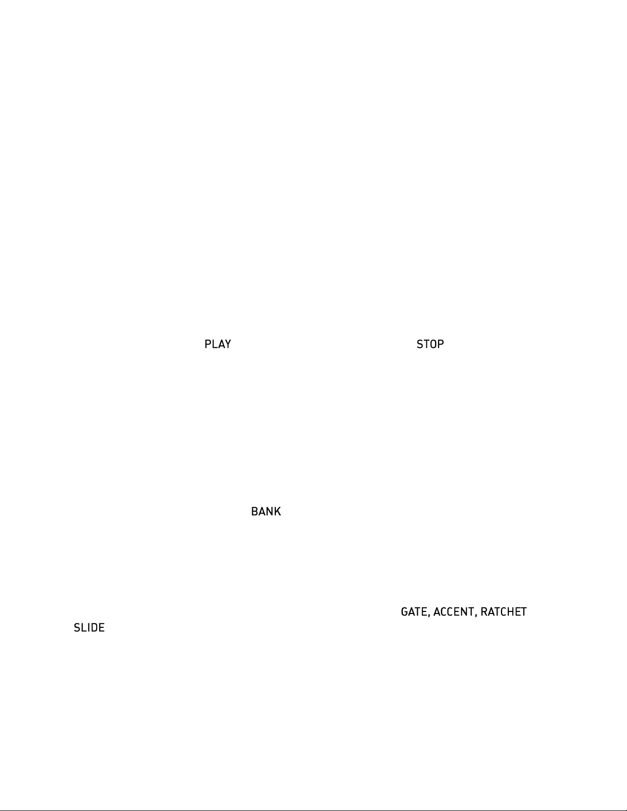
5. Tour of the Panel
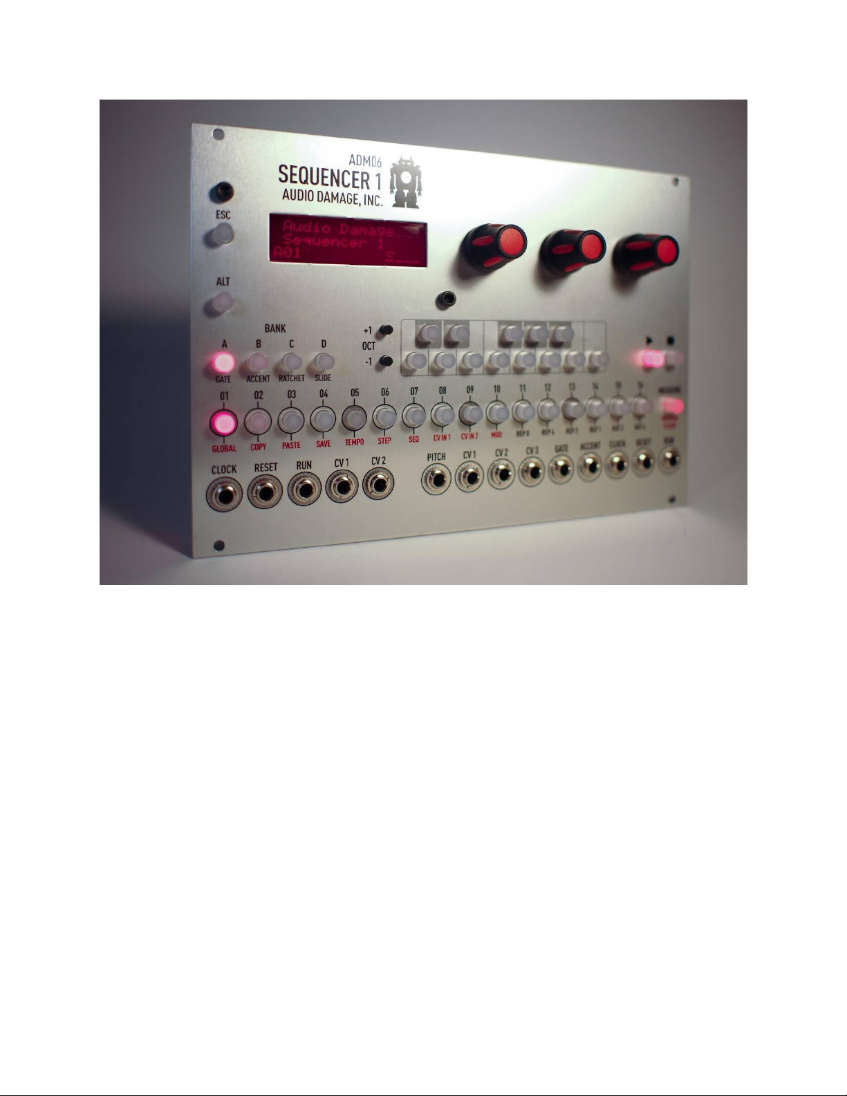
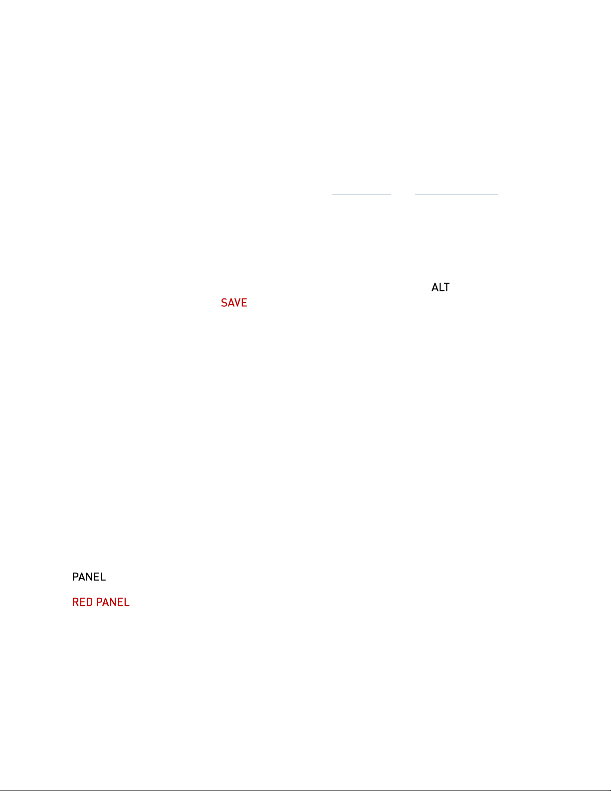
We’ll start by looking at the knobs, buttons, and stuff on the panel. Here’s a drawing of the panel
for your reference if you happen to be reading this manual while away from your equipment:
5.1. Jacks
All of Sequencer 1’s jacks lie in a row across the bottom of the panel. The jacks in the group on
the left, circled with grey, are inputs; those in the group on the right are outputs.
5.1.1. Inputs
These three inputs let you synchronize Sequencer 1 with other modules, so that Sequencer 1
starts and stops upon their command and follows their tempo.
These inputs receive control voltages from other modules. You can assign these signals to
change various things in Sequencer 1, such as using an LFO to modulate the length of the
output gates.
8
Page 9
5.1.2. Outputs
PITCH
This is the output that you’ll use to control the pitch of one or more voltage-controlled oscillators.
It supplies a voltage from zero to five volts, proportionate to the note and octave you program
for each step. You can choose either of two scaling systems for this output: the 1V/octave
convention used by most analog synthesizers and modules, or the Hz/V convention used by
Korg and Yamaha synthesizers.
Of course, nothing says that you have to plug this output into a VCO; like any other voltage
source in your modular synthesizer, you can connect it to just about anything which expects a
voltage.
These three outputs emit voltages in the range -5 to +5 volts. Usually you’ll use them to control
things other than oscillator pitch, such as filter frequency, VCA levels, whatever. You can
program the voltage level at each output for each step in a sequence. Each of these outputs
also has its own low-frequency oscillator which can generate periodic signals in sync with the
pattern. The LFOs can replace the voltage value you program for each step, or they can be
combined with that value in different ways.
This output generates a +5V signal for steps which play a note. Usually you’ll connect it to one
or more envelope generators whose outputs are in turn connected to a VCA’s gain-control input
and a filter’s frequency-control input. When the sequencer plays a note, the gate output goes
from zero to +5V, turning on the envelope generators.
The Gate output has several associated features, including the ability to turn on and off several
times per step. This allows the sequencer to create the often-coveted “ratcheting” effect heard
on early Tangerine Dream albums.
The Accent output is similar to the Gate output. It emits either zero or +5V, and can be
programmed independently from the Gate output. Its usual application is to add accents to
certain steps (perhaps by triggering a different envelope generator than the Gate output) in the
manner of early Roland drum machines. More generally, there’s no reason that you can’t use it
to trigger something entirely independent from the notes generated by the Gate output. For
instance, the Gate output (and probably the Pitch output) could control a bass synth patch while
the Accent output triggers a drum patch.
The Accent output does not have the ratcheting feature of the main Gate output.
These outputs provide timing and control information for synchronizing other devices to
Sequencer 1. The Clock output emits a +5V pulse for each step, with a duration equal to half the
9
Page 10
time of the step. The Reset output emits a short +5V pulse when you press the Stop button. The
Run output is zero when the sequencer is not running, and +5V when it’s running.
If you connect these three outputs to the corresponding inputs on a second Sequencer 1, the
two sequencers will start, stop, and play in sync. Yes, having two Sequencer 1s is more than
twice as fun as having one.
5.2. Knobs
The three knobs on the top right area of the panel are endless encoders for editing parameters.
Generally speaking, rotating a knob changes the parameter with the corresponding position in
the LCD, e.g. twiddle the right-most knob and the right-most parameter currently shown in the
LCD changes. Some features of Sequencer 1 have more than three parameters. The additional
parameters are shown on different “pages” of the LCD. To move from one page to the next,
simply press any of the knobs.
5.3. Play, Stop Buttons
Hopefully you can guess from their names what these buttons do, although there is one subtlety
we’d like to point out. The button starts the sequencer, and the button stops it. (Yes,
you guessed correctly!) When you press the Play button again after pressing Stop, the pattern
starts over with the first step. The subtlety is that if you press the Play button again while the
sequencer is playing, it acts like a pause button. Rather than starting over with the first step, the
sequence will resume with the next step when you press Play once again.
If you’re using an external clock source--which we’ll discuss in detail later--the sequence doesn’t
start playing exactly when you press the Play button. Instead, it starts with the next clock pulse
received after you press the button.
5.4. Bank Buttons
The four buttons on the left labeled are for choosing patterns. Banks are designated by a
letter from A to D. As we mentioned previously, each bank contains 16 patterns; patterns are
designated by a number from 1 to 16. We just happen to have a row of 16 buttons right below
those Bank buttons, so we use those buttons to choose patterns within a bank. To choose a
pattern, first press and release one of the four Bank buttons, then press and release one of the
16 Step buttons. The current pattern is indicated in the lower-left corner of the LCD.
You’ll notice that the Bank buttons have these labels below them: , and
. The Bank buttons are also used to set those four step parameters when editing patterns.
Pressing a Bank button toggles the corresponding step parameter on or off. If a parameter is
turned on, its corresponding Bank button is illuminated.
5.5. Step Buttons
The 16 buttons above the jacks numbered 01 through 16 are the Step buttons. These buttons
have several uses. As described previously, they’re used in conjunction with the Bank buttons to
10
Page 11

select patterns. When editing patterns, the Step buttons are used to select steps within the
pattern; selecting a step lets you alter its parameters such as setting which note it plays.
Step buttons 01 through 10 have additional functions, labeled in red on the panel. To use these
functions, press and hold the button, then press one of the Step buttons. We’ll describe
each of these functions in detail, but here’s a quick summary of what they do:
– accesses settings which affect the overall operation of the sequencer
– makes a copy of the current pattern and places it in a special buffer
– replaces the current pattern with the contents of the special buffer
– stores the current pattern on the Micro SD card
– accesses the tempo setting and related parameters
– accesses individual step parameters, such as note values, CV output values, gate
lengths, etc.
– accesses parameters for the current pattern, such as its length
– assigns the two CV input jacks to do different things, such as changing gate
lengths
– accesses modulators, namely the LFOs
The Copy, Paste, and Save functions execute commands; pressing the button causes
something to happen immediately, and then the system returns to doing whatever it was doing
previously. The other functions invoke different system states or modes, which we usually call
edit modes.
5.5.1. Repeat Buttons
Step buttons 11 through 14 have a second function while Sequencer 1 is playing and is not in
any edit mode. This function, inspired by Replicant, our wildly popular beat-repeater plug-in,
causes the sequencer to repeat some of the steps it played just before you pressed the button,
for as long as you hold the button. How many steps it repeats depends on which button you
press, as reflected by the labels. The button labeled repeats just the last step played, for
as long as you hold the button. repeats the last two steps, and and repeat the
last four and eight steps respectively.
When you release the button, the pattern resumes playing at the step it would next play if you
hadn’t pressed the button at all. In other words, you can freely repeat any number of steps
within the currently playing pattern, at any time, and the repetitions will enhance the pattern
rather than disrupting it. This makes the Repeat function ideal for improvisation, either live or in
the studio.
11
Page 12
Repeats can also be activated with one of the two control-voltage inputs, so you can use
voltage sources like LFOs to trigger repeats in predictable or random ways.
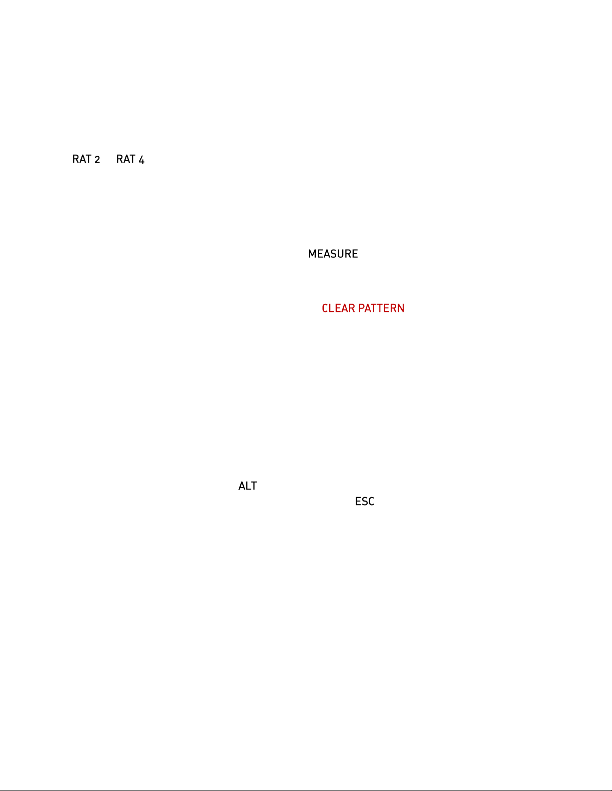
5.5.2. Ratchet Buttons
Step buttons 15 and 16 also have a second performance-oriented function: ratcheting. Pressing
or while the sequencer plays causes the Gate output to fire twice or four times per
step, rather than once.
5.6. Measure Button
If you’ve been paying close attention, you may be wondering how Sequencer 1 lets you work
with patterns of up to 64 steps if there are only 16 Step buttons for working with those steps.
The answer is the button on the far right labeled . For patterns with more than 16
steps, pressing this button flips from one measure of 16 steps to the next. The current measure
is indicated in the LCD.
The Measure button has a second function labeled . Pressing and holding the
ALT button, then pressing the Measure button erases the current pattern, setting all of its
parameters and steps back to default values. Obviously you should use this button with caution,
which is why we put this function on the far side of the panel away from the other command
buttons.
Finally, when the sequencer is playing, the Measure button blinks when every fourth step is
played. This provides visual reassurance that the sequencer is in fact playing when the current
step is not in the currently visible measure, and hence you can’t see the Step LEDs merrily
blinking along.
5.7. ESC, ALT Buttons
We’ve already mentioned that the button is used in conjunction with the Step buttons to
execute commands and change edit modes. Pressing the button, short for Escape, takes
you out of whatever edit mode Sequencer 1 is currently in, returning you to the default mode
that Sequencer 1 starts in when powered up.
6. Making Patterns
So far we’ve been waving our hands a little bit in that we haven’t really described how
Sequencer 1 makes music. Making music with Sequencer 1 boils down to making patterns, and
making patterns means adjusting the parameters of the pattern and the parameters of the
individual steps within the pattern. You do this by selecting different edit modes with the ALT
functions of the Step buttons. Each edit mode displays one or more pages of parameters in the
LCD. You change the parameters by turning the knobs. Since Sequencer 1 lets you switch
modes and change parameters while it’s playing a pattern, you can create patterns in an
improvisational manner, which means it’s a lot more fun than it sounds like when it’s written
down in gory detail. Nonetheless, we’ll plow through the gory details because we promised you
12
Page 13
that we’d explain everything so that you don’t have to figure out how to use Sequencer 1 all by
yourself.
The three edit modes you’ll use most are Tempo, Step, and Seq. We’ll look at each in turn, but
first we’ll describe some features which apply to all three modes.
6.1. Entering Notes, Gates, Etc.
When Sequencer 1 is in any of the three pattern-editing modes (Tempo, Step, or Seq), you can
do several things with the Note, Step, and Bank buttons. The Step buttons let you choose which
step is the selected step. To select a step, press and hold the appropriate Step button; its LED
will illuminate brightly. If the pattern has more than 16 steps, press the Measure button to switch
from one measure of 16 steps to the next.
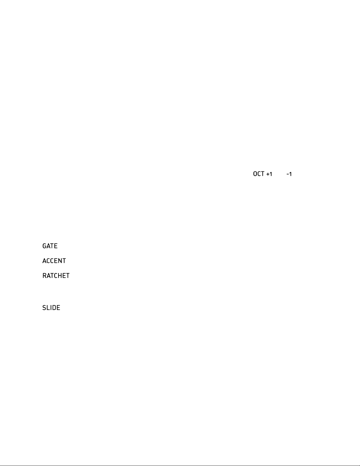
The note that the selected step plays is indicated by two things: one of the Note buttons
illuminates, and an octave indicator appears in the lower-left corner of the LCD. Press one of
the Note buttons to change which note the selected step plays. Press the and buttons
to change the note’s octave. The octaves are numbered from 1 to 5. You will of course have to
tune your VCOs appropriately. Sequencer 1 puts out appropriate voltages for playing notes
chromatically, but your VCO has to be adjusted by hand so that it generates a frequency which
corresponds to the note shown by Sequencer 1’s Note buttons.
The four Bank buttons control four parameters of the selected note, as follows. Press the
buttons to toggle the corresponding parameter on or off.
– if illuminated, the Gate output jack will turn on when the selected note plays.
– if illuminated, the Accent output jack will turn on when the selected note plays.
- if illuminated, the selected step’s Gate output jack will turn on and off two to four
times when the step plays, rather than just once. How many times is specified by the Ratchets
parameter discussed below.
– if illuminated, the Pitch output voltage will move smoothly from the previous note’s
value to the selected note, rather than jumping. This recreates the pitch-sliding effect made
immortal by Roland’s TB-303 bass synthesizer/sequencer.
The Gate parameter for each step is also reflected by the Step button LEDs. If a step’s Gate is
on, the Step LED will be dimly illuminated. You can toggle the step gates on/off by tapping the
Step buttons. You can even toggle a bunch of step gates in succession by dragging your thumb
along the Step buttons.
To reiterate, a long press means select that step, and a quick tap means toggle that step’s gate
on or off. The selected step’s parameters are altered by the Note buttons, the Bank buttons, and
the knobs when you’re in the Step edit mode. We’ll look at the three editing modes next.
13
Page 14

Tempo Swing Slid
133.7 12% 5
Oct:2 +Ξ-_
Len Mode Trans
37 <---> +12
Oct:2 +Ξ-_
6.1.1. Tempo Mode
This mode, as you can almost certainly guess, access
parameters related to how fast Sequencer 1 plays. There is only
one page of parameters in this mode, which are:
Tempo
Determines how fast the sequencer moves from one step to the next. This value is expressed in
beats per minute, and ranges from 10 to 240. (Since a beat is assumed to be a quarter note,
and Sequencer 1 organizes patterns into measures of 16 steps, four steps usually correspond
to one beat.) Note that the tempo setting applies to all patterns. This parameter has no effect if
Sequencer 1 is using an external clock source.
Swing
Alters the rhythmic feel of the pattern by delaying every other step relative to the clock. This
value is expressed as a percentage, and ranges from 0 to 99%. 0% means straight timing, i.e.
no swing. 50% means that every other step is delayed by half of a step’s nominal duration. This
parameter has no effect if Sequencer 1 is using an external clock source. Note, however, that
Sequencer 1’s Clock output is affected by this parameter, so you can pass the ability to swing
on to other modules.
Slide
For steps with the Slide setting turned on, this parameter sets how quickly the slides happen.
This value is expressed in arbitrary units ranging from 1 to 20. It has no effect if none of the
steps in the pattern have Slide turned on. Adjust it to taste after you’ve changed the tempo.
6.1.2. SEQ Mode
This edit mode accesses parameters which apply to the current
pattern. There are four pages of parameters.
Len
(Short for Length) Sets the number of steps in the pattern. Patterns can have 1 to 64 steps.
Mode
(Short for Stepping Mode) Determines how the sequencer moves from one step to the next, and
what it does when it reaches the last step in a pattern. The usual behavior is to progress from
one step to the next, from left to right, and start over with the leftmost step. Use the other modes
to generate melodic and/or rhythmic variations from one pattern. In the following descriptions,
we’ll use N to designate the number of steps in the pattern. (Thus the “Nth step” is the highestnumbered step in the pattern.) The modes are indicated in the LCD in a somewhat pictorial
manner:
14
Page 15

Symbol
Meaning
--->
The sequencer moves from left to right, one step at a time. After it plays the Nth
step, it jumps back to step 1.
<---
The sequencer moves from right to left, one step at a time, starting with the Nth
step. After it plays step 1, it jumps back to the Nth step.
<--->
The sequencer starts with step 1, moves from left to right until it reaches step N,
then moves from right to left back to step 1. On each cycle, it plays steps 1 and N
once.
<<->>
The sequencer starts with step 1, moves from left to right until it reaches step N,
plays step N again, then moves from right to left back to step 1. On each cycle, it
plays steps 1 and N twice.
skip
Starting with step 1, the sequencer plays every other step, i.e. steps 3, 5, 7, etc. If
the pattern’s length is an odd number, it will play step 2 after playing step N (and
then play steps 4, 6, etc.).
walk
The sequencer moves in a manner described as a random walk by math geeks. It
moves to either the next step or the previous step, choosing its move randomly. If it
reaches the Nth step, it will either play the (N-1) step next, or the first step next.
Similarly, after playing the first step, it might jump to the Nth step or it might play
the second step.
jump
The sequencer picks the next step completely at random. It may or may not play
the same step more than once.
halt
The sequencer just sits on the first step, playing it over and over again. There’s
probably some IDM sub-genre in which unvarying single-note sequences are
compositionally useful, but the real intent behind this mode is using it in
conjunction with the Step Position CV assignment, described later under “Control
Voltage Inputs”.
Trans
(Short for Transpose)
Transposes all of the notes in the pattern. This value is set in semitones and can be either
positive or negative. The notes are forced into the current key after this transposition is applied,
so that transposition always occurs diatonically. In other words, you can twiddle this knob and
the results will stay in key. Note, however, that this control has a range of ±48, or up and down
four octaves. Since the Sequencer 1 Pitch CV output has a range of five octaves, it’s entirely
possible that extreme settings of the Transpose parameter would push your pattern outside of
the available pitch range. Nothing bad will happen if you do this, but the results might not be
particularly musical.
15
Page 16

CV Output Modes
CV1 CV2 CV3
Lin LFO+ LFO
Scale Tonic
Dorian F
CV1, CV2, CV3 Output Modes
The Pitch CV output always generates voltages based on the
note values programmed for each step in the sequence. The
other three CV outputs can each operate in one of several
different modes, as follows:
Lin (short for Linear) – The CV output voltage depends on the corresponding CV values for
the steps in the sequence. What you set is what you get.
LFO – The CV output voltage comes directly from the corresponding LFO. CV1's voltage is set
by LFO1, CV2's voltage by LFO2, etc. This mode is the simplest way to make use of an LFO,
since it connects the output of the LFO directly to the CV output jack.
LFO+ – The CV values in the pattern are added to the LFO; their sum sets the CV output
voltage.
LFO× – The CV values in the pattern are multiplied by the LFO to determine the output
voltage.
We’ll have more to say about the LFO-related modes later, when we talk about the LFOs
themselves.
Scale and Tonic
This page shows you the scale and tonic for the pattern, which together make up the musical
key. The notes of the pattern are constrained by the key. If you
enter notes which are not in the current key, those notes will be
moved to the nearest in-key notes when played. This process is
“non-destructive” in that the pattern itself is not altered.
This has several useful implications. Transposition happens intelligently. You can transpose a
pattern both manually and with an appropriate CV-input mapping (as described in the ControlVoltage Inputs section) and the notes of the pattern will stay in key. You can experiment by
changing the scale and/or tonic to create different melodies from the same set of notes. If you’re
bravely editing your pattern in front of a live audience, the key settings will greatly reduce the
hazard of playing the wrong notes.
Scale
The scale is the set of semitones, out of the twelve which make up an octave, which define the
intervals present in the key. We use the term “scale” to include both that general notion as well
as the more specific term mode. Browsing through Sequencer 1’s list of scales, you’ll find
entries which are usually referred to as modes.
16
Page 17

1
The default scale is the chromatic scale, which contains all 12 notes in the octave. If you use
this scale, the notes of each step in the pattern will play exactly as you entered them. Any
transposition you apply will move the notes by half steps.
You can see the notes in the scale by looking at Note buttons. If a note is present in the scale,
its Note button is illuminated. The lighted buttons also reflect the setting of the Tonic parameter.
For example, if the Scale is set to Major and the Tonic is set to C, the Note buttons
corresponding to the white keys on a piano will be illuminated. Change either the Scale or the
Tonic and you’ll immediately see the notes present in the resulting key. You’ll hear the effects as
well, if the sequencer is playing.
There are over 40 different preset scales available. Since you can see what they do by looking
at the Note LEDs, we won’t list them here1. If you can’t find one that suits your needs, there are
eight slots for user scales. These work in the same manner as the preset scales, but you can
choose which notes are present in the scale by pressing the Note buttons. The eight user scales
are saved on the Micro SD card, and are shared by all patterns. You’ll find the user scales at the
end of the scale list. User scales are saved automatically when you save your pattern or leave
the Scale and Tonic editing page.
Tonic
The Tonic is the first (lowest-pitched) note in the key. Usually you’ll set this parameter to the
note corresponding to tonal center of the pattern, since this will probably produce the results you
expect if you transpose the pattern. On the other hand, setting it to something else might
produce interesting results, too. Since the Scale and Tonic parameters don’t actually alter the
notes you enter, you can experiment with them without fear of doing irreparable harm to the
pattern itself.
You may be wondering about the relationship between the Tonic and the Transpose parameter
we mentioned previously. One way to think about it is this: the Tonic, together with the Scale,
determines the series of intervals as you play upwards from the tonic note. A Major scale, to
pick an easy example, has a series of two whole steps, a half step, three more whole steps, and
one half step. The key of C Major starts with C and uses that series, playing the notes C, D, E,
F, G, A, B. If you set your pattern to use C Major, it will always play those notes, regardless of
how you transpose it. If you change the Tonic to D, the same series of intervals will be used and
your pattern will play the notes D, E, F#, G, A, B, C#, regardless of how it is transposed. The
Tonic, together with the Scale, determines a set of which notes will be played. Transposing
moves your notes up or down within that set.
The scale presets were drawn from Wikipedia’s "List of musical scales and modes," found here:
http://en.wikipedia.org/w/index.php?title=List_of_musical_scales_and_modes&oldid=634940322
Sequencer 1’s complement of scales includes every entry on that list which can be expressed as a subset
of the chromatic scale.
17
Page 18

Pitch CV
Hold
CV1 CV2 CV3
+012 -147 +333
Oct:2 +Ξ-
GtTim AcTim Rats
43% 72% (2)
Oct:2 +Ξ-_
Pitch CV Mode
The Pitch CV operates in one of two modes which determine
what happens when the sequencer plays steps whose gate is
off. The two modes are:
Hold – The Pitch CV output retains the voltage it generated the last time it played a step
whose gate was on. This is the default mode, and usually the one you’ll use. It prevents the
pitch of the note from changing unexpectedly when the sequencer advances to an empty note,
particularly if the sequencer is driving a patch with envelopes long enough to create a legato
effect.
Free – The Pitch CV output always changes to whatever note value is programmed for each
step. This mode may be useful if you’re using the Pitch CV output for something other than
controlling the pitch of the oscillator(s) in your patch.
6.1.3. Step Mode
This edit mode accesses parameters for each step. The parameters shown in the LCD are for
the selected step. To select a step, press and hold the appropriate Step button. Its LED will light
up brightly. You can select steps freely while the sequencer is playing.
Step mode has two pages of parameters.
CV1, CV2, CV3
These three parameters set the voltages generated at the three
CV output jacks. The values are displayed in 100ths of a volt,
and range from -500 to +500. For instance, setting CV2 to -123
means that the CV 2 jack will output -1.23V when the step plays.
GtTim
Sets how long the Gate output jack will turn on when the step plays. This value is expressed as
a percentage of the duration of the step, and ranges from 1% to 100%. Since 100% means that
the Gate stays on for the entire duration of the step, the LCD
displays Tie rather than 100%, indicating that the step is
effectively joined to the next one.
AcTim
Same as the Gate setting, but for the Accent output jack.
Rats
Short for ratchets, this sets how many times the Gate output turns on and off if the Ratchet Bank
button is illuminated for the step. You can select 2, 3, or 4. If the Ratchet button is not turned on,
this parameter is displayed with parentheses around it because it has no effect.
18
Page 19

Shape Length
Rect 3/8 27
LFO 2
7. Low-Frequency Oscillators (LFOs)
Lurking within Sequencer 1 are three low-frequency oscillators. Like other LFOs, these
oscillators generate periodic voltage signals which can be used to control other modules.
Sequencer 1’s LFOs have a wide variety of wave shapes and are synchronized with the pattern,
regardless of whether you’re using internal or external clocking. At the risk of getting carried
away with ourselves, we’ll mention that you’d pay a substantial fraction of Sequencer 1’s price if
you purchased LFOs this powerful as separate modules.
7.1. Selecting LFOs
Press and hold ALT then press to access the LFO edit pages. Pressing Mod again while
holding ALT advances the LCD from one LFO’s parameters to the next. The LCD indicates
which LFO is currently selected. Each LFO has two pages of parameters.
7.2. LFO Parameters
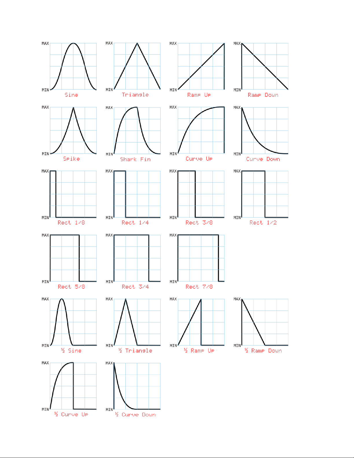
Shape
The Shape parameter lets you choose one of many different
shapes for the LFO. The shape describes how the LFO's output
changes over time. Usually we speak of the LFO's shape in
terms of what its output does in one cycle; most shapes operate
in a predictable manner, generating an output signal which repeats over and over, once per
cycle. (The randomly generated shapes are the exception.)
The available shapes are shown in the following illustration. Each drawing represents one cycle
of the LFO. The actual output voltages from the LFO depend upon the settings of its Amplitude
and Range parameters, which we’ll describe shortly. In the drawings we’ve labeled the scale
with arbitrary values of MIN and MAX representing the LFO’s minimum and maximum output
voltages.
19
Page 20
20
Page 21

Shape
Behavior
Random Step
At the beginning of each cycle, the LFO’s output jumps to a randomly
chosen value and stays there for the duration of its cycle.
Random Ramp
At the beginning of each cycle, the LFO chooses a new value at random
and moves to that value in a linear manner over the duration of its cycle.
Random +/-
Same as Random Step but the value is always either MIN or MAX.
Random +0-
Same as Random Step but the value is always MIN, MAX, or halfway in
between.
Range
MIN
MAX
+/-
-5V
5V
+
0V
5V
-
-5V
0V
Amp Range Phase
53% +/- 116
LFO 2
There are some randomly generated shapes which don’t lend themselves to drawings. They
are:
Length
The Length parameter determines how long it takes for the LFO to complete one cycle; in other
words, how fast it runs. The LFO Length is expressed in steps. For example, if Length is set to
3, the LFO will complete one cycle every time the sequencer plays three steps. Note that Length
can be higher than the number of steps in the pattern, and has an upper limit of 256, meaning
that you can set up the LFO so that the pattern repeats several times before the LFO completes
one cycle.
Amplitude, Range
These parameters work together to set the voltage range of the
LFO’s output. The Range parameter chooses the minimum and
maximum output voltages for the LFO, that is, the range of voltages it can generate. There are
three choices, as shown in this table:
The Amplitude parameter sets how much of that range the LFO actually produces, and is
expressed as a percentage from zero to 100%. 100% means that the LFO’s output will swing
between the minimum and maximum values set by the Range parameter. 50% means that the
output will cover half of that range, starting at zero volts, and 0% means 0V comes out. For
example, a Range setting of + and an Amplitude of 40% will make the LFO’s output vary
between 0V and +2V. A Range of +/- and an Amplitude of 70% will produce output voltages from
-3.5V to +3.5V.
21
Page 22

Phase
The Phase parameter determines where the LFO starts within its cycle when the pattern starts
playing. Thanks to the LFO's roots in mathematical functions, the phase value is expressed in
degrees, where a complete cycle consists of 360 degrees. The following diagram shows how
the phase parameter controls where the LFO's cycle starts, for several different shapes:
7.3. Using LFOs
Now that we’ve described the LFO parameters, we’ll point out some subtleties which may help
you make the most of the LFOs.
7.3.1. Pattern Synchronization
Each LFO’s cycle is always reset to the beginning when Sequencer 1 starts playing a pattern.
This means that the LFOs are always synchronized to the pattern, so that their effect on other
22
Page 23

modules is predictable and repeatable. However, once started, the LFOs can cycle
independently of the pattern. For instance, if the pattern is 16 steps long and an LFO’s Length
setting is 64, the pattern will play four times before the LFO completes one cycle. Conversely, if
the pattern’s length is 64 and the LFO’s is 16, the LFO will complete four cycles while the
pattern plays once. This can become more interesting if the pattern length and LFO length
aren’t simple multiples of each other. If the pattern is 16 steps long and the LFO’s length is 15,
for example, the LFO will move out of phase with the pattern as the pattern plays, eventually
lining up again with the beginning of the pattern. Consider also that each LFO can have a
different length, and hence can drift in and out of phase with the pattern (and with the two other
LFOs) in its own way.
7.3.2. LFOs As Simple Envelope Generators
The LFOs are very tightly synchronized to the sequencer. LFOs start exactly in sync with steps.
This means that you can use a LFO with a length of 1 as a simple envelope generator. The
Ramp Down and Curve Down shapes work particularly well for this. Set a CV’s Output Mode to
LFO and presto, you’ve got a simple decay envelope which can drive a VCA or a filter’s
frequency input directly. If you use one of the half-cycle shapes (designated by a ½ at the
beginning of their names) and set the LFO’s length to 2, you’ll get an envelope which fires on
every other step.
Now, suppose you want that envelope to fire only on certain steps. This is where the LFOx
(multiply) CV Output Mode comes into play. This mode multiplies the LFO’s level by the CV level
set in each step. If the step’s CV level is zero, the CV output will be zero (since zero times
anything is zero). If the step’s CV level is, say, +4.0V, and you’re using the Ramp Down LFO
shape and a LFO Length of 1, you’ll get an output voltage that sweeps from +4V to 0V for that
step. This means that you can program different peak values for the sweep for each step in the
sequence—including zero values and negative values. You can also scale the peak values all at
once by adjusting the LFO’s Amplitude parameter.
7.3.3. Creating Accents
Imagine you’re using one of the CV outputs to control a filter’s frequency by entering different
values for each step’s CV parameter. Now suppose you’d like to add an accent to every eighth
step by opening the filter more. You could use the ACC output, or you could enter new CV
values for the appropriate steps. You could also use the LFO. Set the LFO’s Shape to Rect 1/8
and its Length to 8. Then set the pattern’s CV Output Mode to LFO+. This will add a rectangular
pulse to the CV output on every eighth step, starting with the first step. If you change the LFO’s
Phase parameter, you’ll change the steps, relative to the beginning of the pattern, which the
accents fall on. If you change the Shape to Rect 2/8, you’ll get the accent on pairs of steps:
every eight step and each immediately following step. Finally, change the LFO’s Amplitude
parameter to change the height of the pulse.
23
Page 24

8. Other Pattern Commands
There are a few utility commands for working with patterns. You can duplicate entire patterns, or
individual measures within a pattern, with copy and paste commands. You can also erase entire
patterns and save them to the Micro SD card.
8.1. Copy & Paste
You can copy patterns from one place to another, so that you can create patterns similar to one
another without creating each one entirely from scratch. You can also copy and paste single
measures (of 16 steps) within the same pattern.
8.1.1. Copying Entire Patterns
Press and hold ALT, then press , to make a copy of the current pattern, placing it in a
temporary buffer. If you switch to a different pattern, pressing ALT and places the
contents of this buffer into the pattern, erasing anything that was there previously. So, to make a
copy of a pattern in another pattern slot:
Press one of the Bank buttons, then one of the Step buttons, to select the source
pattern.
Press and hold ALT, then press Copy, to make a copy the source pattern.
Press one of the Bank buttons, then one of the Step buttons, to select the destination
pattern.
Press and hold ALT, then press Paste, to place a copy of the source pattern in the
destination.
8.1.2. Copying Measures
Copying and pasting measures within one pattern works much the same as copying and pasting
entire patterns, except that you change measures within the current pattern rather than
switching patterns. For example, to copy the first measure to the third measure:
If necessary, press the button one or more times to switch to the first
measure.
Press and hold ALT, then press Copy, to make a copy of the first measure. (This actually
makes a copy of the entire pattern, which obviously includes the first measure.)
Press the button twice to switch to the third measure.
Press and hold ALT, then press Paste, to overwrite the third measure with a copy of the
first measure.
24
Page 25

Copying and pasting measures affects only the information in the steps of the measure.
Information which affects the whole pattern (such as the scale, LFO settings, etc.) is
unchanged.
8.2. Saving Patterns
Patterns exist in RAM as you create and play them. RAM is a quaintly imprecise acronym, but
what it means in practical terms is that anything stored there is lost when the power goes off.
Sequencer 1 uses a Micro SD card to store patterns and other information so that you don’t
have to leave your modular synth turned on 24/7. (Maybe you do that already. That’s fine, but
you should save your patterns anyway, just for safe keeping.)
To save the current pattern, press and hold ALT, then press SAVE. This saves only the currently
active pattern; you have to explicitly save each pattern individually. Saving is quick and easy
and can be done at any time without interrupting anything. Saving frequently is a good habit to
cultivate.
8.3. Clearing Patterns
If you want to erase everything in the current pattern, press and hold ALT, then press
(the button). This resets every parameter and step in the current pattern to
their default values. Yes, you should exercise caution when using this command; there is no
undo, although if you accidentally erase a pattern which you have previously saved, you can
restore that pattern by power-cycling your system, causing Sequencer 1 to reload all patterns.
9. External Clocking
Sequencer 1 can use signals from other modules to control its tempo, start and stop patterns
playing, and reset the pattern to its first step. These external clocking features can be used to
make Sequencer 1 behave in a predictable manner in conjunction with other devices, such as
another Sequencer 1 (hint, hint). They can also be used to make Sequencer 1 behave in an
unpredictable manner. Read through the following descriptions of the input jacks and then
imagine patching three different unsynchronized LFOs into these three jacks.
To use these features, you must first change one of Sequencer 1’s Global settings, as described
under Clock Source, Patterns Switch. The Clock and Reset input jacks are mostly interested in
when their signals that go from 0V or less to some positive value--a rising edge as it’s known in
engineering circles.
This jack sets Sequencer 1’s tempo based on the frequency of the incoming signal. For
instance, you could plug the output of an LFO into the Clock jack, and change Sequencer 1’s
tempo by changing the LFO’s frequency. Sequencer 1 uses each complete cycle to determine
the duration of one step; for instance, if the hypothetical LFO’s signal has a frequency of 10Hz,
then each step will last 1/10th of a second.
25
Page 26

CV1 Assignment
Step Position
A rising edge on the Reset jack will make Sequencer 1 reset the step index back to the first step
of the pattern (where the first step is determined by the pattern’s cycle mode). The index
changes in sync with the incoming clock signal; that is, the pattern will jump to the first step
upon receiving a rising edge at the Clock jack after receiving a rising edge on the Reset jack.
The Run jack makes Sequencer 1 play or stop. A positive input voltage makes it play, zero volts
or less makes it stop. Note that the Run jack is not what makes Sequencer 1 play the next step-
-that’s the job of the Clock jack.
10. Control-Voltage Inputs
Sequencer 1 has two input jacks, labeled and , which accept control voltages. They
expect voltages in the range of -5V to +5V, although in most instances negative voltages are
ignored. Each CV input can be independently assigned to one of several functions. These
assignments are made globally, that is, they apply to all patterns. The available functions for CV
control are as follows:
(Nothing)
If you’re a Nihilist, this is the assignment for you. The control
voltage has no effect. This setting can be handy if you need to
temporarily disable the control voltage input and you’ve already got a bunch of patch cords
connected at only one end dangling from your modular.
Gate Length
The control voltage changes how long the gate output stays on, relative to its per-step setting.
Positive voltages increase its length, up to a maximum of twice its programmed length. Negative
voltages decrease the gate length, down to a minimum of one-fourth its programmed length.
Step Position
The control voltage sets the current step position, overriding the behavior set by the pattern’s
Stepping Mode. A positive voltage sets the step position relative to the length of the pattern and
proportional to the voltage level. In other words, zero volts sets the position to the first step, a
maximum voltage of +5V sets the position to the last step in the pattern, and any other voltage
will select a step somewhere in between. Negative voltages are ignored. The step position is
updated in time with the clock (either internal or external).
Stepping Mode
The control voltage sets the Stepping Mode, overriding the pattern’s Stepping Mode setting. A
positive voltage is linearly mapped to one of the many stepping modes. 0V chooses the first
mode, +5V chooses the last mode, a small voltage chooses the second mode, etc. Negative
voltages are ignored.
26
Page 27

Repeats
The control voltage triggers step repeats in the same manner as the step buttons, as described
under Repeat Buttons. Positive voltage inputs activate repeats, negative voltages are ignored.
There is a dead zone near zero so that a small voltage won’t park Sequencer 1 in an endless
series of repetitions. A voltage of 1V to 2V causes one step to be repeated, 2V to 3V repeats the
last two steps, 3V to 4V repeats the last four steps, and above 4V repeats the last eight steps.
The panel buttons get priority over this control-voltage assignment. In an argument over who
gets to say which steps repeat and when, you’ll always win.
Ratcheting
The control voltage triggers ratcheting in the same manner as the step buttons, as described in
the Ratchet Buttons paragraph. Positive voltage inputs activate ratcheting, negative voltages
are ignored. There is a dead zone near zero so that a small voltage won’t make every step
ratchet. A voltage of 1.25V to 2.5V triggers two gate pulses per step, 2.5V to 3.75V triggers
three pulses per step, and above 3.75V triggers four pulses.
Transposition
The control voltage is quantized into semitones with the usual 1V/octave convention and added
to each step’s programmed pitch to transpose the pattern. As you’d probably guess, positive
voltages transpose the notes upward, negative voltages transpose them downward. You might
also guess that this transposition is constrained by the Pitch CV output’s usual range, and you’d
be right.
Pattern
The control voltage changes which pattern plays. Positive voltage inputs choose from the (up to)
16 patterns in the current bank. Unused patterns are ignored, as are negative voltages. For
example, suppose you’ve used patterns 2, 3, 5, and 11 in the current bank. An input voltage of
zero to 1.25V will select pattern 2, a voltage of 1.25 to 2.5V will select pattern 3, a voltage of
2.5V to 3.75V will select pattern 5, and any higher voltage will select pattern 11.
When the voltage changes, the pattern will change as dictated by the Pattern Switch option
described under Clock Source, Patterns Switch. Also, the pattern changes in response to this
control-voltage assignment only when the sequencer is in its default, non-editing mode. This is
to prevent the confusion which would arise if the pattern switched while you were editing it.
11. Measure Display
The LCD displays four symbols in the lower-right corner which indicate the length of the pattern
and which measure of the pattern is currently visible on the STEP buttons. If the sequencer is
playing, the symbols also indicate which measure contains the step currently being played.
There are four distinct symbols:
27
Page 28
Symbol
Meaning
_
Empty measure
-
Non-empty
measure
Ξ
Visible measure
+
Playing measure
Audio Damage
Sequencer 1
A03 +Ξ-_
Clock Patterns
Source Switch
Int By patt
Since a pattern has up to four measures of 16 steps, the display always shows four of the above
symbols. Here’s an example of how the symbols might appear on the LCD:
This tells you several things:
The + indicates that the sequencer is playing a step in the first measure
The Ξ indicates that the second measure is displayed on the LEDs. This means
that you won’t see the step advancing from one LED to the next because that +
told you that the sequencer is playing a step in the first measure, and you’re
looking at the second measure.
The – and _ tell you that the pattern is between 33 and 48 steps long: the –
shows that the third measure (which starts with step 33) is used, while the _
shows that the fourth measure (which starts with step 49) is unused.
12. Global Options
There are a number of settings which affect Sequencer 1's operation globally, regardless of
which pattern is currently active. You probably won't have to change them very often.
12.1. Clock Source, Patterns Switch
Sequencer 1’s tempo comes from one of two reference clocks:
its own, or an external signal provided through its input
jack. Thus, unsurprisingly, the Clock Source option has two
settings:
Int (short for Internal) - If you want the sequencer to happily play by itself, using its internal
clock source, use this setting.
28
Page 29

Output Modes
Gate Acc Scale
Strg Norm Hz/V
Ext (short for External) - On the other hand, if you want the sequencer to play in time with
some other sequencer, or you want to do something exotic like controlling the sequencer’s
tempo with an LFO, use this setting.
This option determines whether pattern changes happen at the ends of patterns or between
steps. It applies to pattern changes either in response to you pressing the Bank and Step
buttons or in response to a CV input.
By patt – the sequencer waits until it reaches the end of the current pattern before
switching to the new pattern.
By step – the sequencer changes patterns before playing the next step (but does not
interrupt the current step).
Both modes have their uses. Switching by pattern means that you won’t interrupt the current
pattern, and hence this mode might be considered less risky for live performances.
12.2. Gate/Accent Output Modes, Pitch Output Scale
Mostly for compatibility with older analog synthesizers, the Gate
and Accent output jacks can each operate in one of three
different modes, as follows:
Norm (short for Normal) - the output is usually zero, and rises to +5V when the output turns on.
Use this setting for most Eurorack modules such as envelope generators and VCAs.
Inv (short for Inverted) – the output is inverted, that is, usually +5V and falls to zero when the
output turns on. This mode is useful for many older Korg and Yamaha synthesizers, and also
works with the contemporary Korg MS-20 Mini.
STrg (short for S-Trig, which is short for Shorting Trigger) – the output has a high-impedance,
open-circuit output which is shorted to ground when the output turns on. This mode may be
useful with some older Moog synthesizers and modules.
The Pitch CV output can operate in one of two different pitch-control scaling conventions,
labeled Scale in the LCD. They are:
V/oct – This mode is used by most Eurorack oscillators and analog synthesizers, new and
old. One volt raises the pitch by one octave.
Hz/V – This mode is used by some Korg and Yamaha synthesizers. Doubling the voltage
raises the pitch by one octave.
29
Page 30

Display
Contrast
12
System Info
Version
1.1.5.25
12.3. Display Contrast
Adjust this setting to make the display most legible from your
current seated, standing, or lying position.
12.4. System Information
This page shows the version number of the software installed in
your sequencer. If this number is less than the version number
of the software available at Audio Damage's website, you may
want to update your sequencer.
30
Page 31

13. Updating the Firmware
Audio Damage will occasionally make available new versions of the Sequencer 1 software in
order to add new features and correct defects. You can obtain these updates from our website
here: http://www.audiodamage.com/hardware/product.php?pid=ADM06
Installing the new firmware is a simple process, as follows:
Turn off the power to your Eurorack system. Yes, we’re sure that you’re both intelligent
and careful, but nonetheless we’d like to take this opportunity to tell you that working on
electrically powered equipment with the power turned on is hazardous to both you and
the equipment.
Remove Sequencer 1 from your cabinet. You may or may not be able to get away with
leaving the power cable connected.
Remove the Micro SD card from its socket on the back of Sequencer 1. The socket has
a metal cover which slides slightly and then opens on hinges. Pay attention to the
orientation of the Micro SD card before you remove it; obviously you’ll have to put it back
in the same orientation shortly.
Using a standard adapter, mount the Micro SD card on a personal computer. Any
operating system which can read and write a FAT-formatted removable medium and
decompress .zip files will do; this means just about any version of Windows, OSX or
Linux.
Obtain the firmware from our website, and unzip the file. The resulting file will be named
Seq1_fw.srec.
Copy the Seq1_fw.srec file onto the Micro SD card. While you’re doing this you might
notice other files on the card. Some of those files are your pattern files. If you’d like to
make backup copies of those files, you can do so simply by copying them to some other
storage device, such as the main drive in your computer.
Unmount the Micro SD card, put it back in the socket on Sequencer 1, and reinstall
Sequencer 1 in your cabinet.
Turn the power back on. You’ll see a message informing you that the new firmware has
been recognized and is being installed. The installation takes a little less than 30
seconds to complete, whereupon Sequencer 1 will restart and be ready to go.
Since parts of this process are easier to demonstrate than to describe, we’ve provided a video
that shows you exactly what happens:
http://youtu.be/UZp8Mi8VdDc
31
Page 32

14. And Finally…
Thank you for purchasing Sequencer 1. We make every effort to ensure your satisfaction with
our products, and want you to be happy with your purchase. Please write to us at
info@audiodamage.com if you have any questions or comments.
32
 Loading...