

Page 1
Ronin User’s Guide
Audio Damage, Inc.
Release 1.5
1
Page 2

The information in this document is subject to change without notice and does not represent a commitment on
the part of Audio Damage, Inc. The software described by this document is subject to a License Agreement
and may not be copied to other media except as specifically allowed in the License Agreement. No part of this
publication may be copied, reproduced or otherwise transmitted or recorded, for any purpose, without prior
written permission by Audio Damage, Inc.
VST is a trademark of Steinberg Media Technologies GmbH. All other product and company names are
trademarks of their respective owners.
© 2005, 2009 Audio Damage, Inc.
All rights reserved.
2
Page 3

License Agreement
BY INSTALLING THE SOFTWARE, YOU ARE CONSENTING TO BE BOUND BY THIS AGREEMENT. IF YOU DO NOT
AGREE TO ALL OF THE TERMS OF THIS AGREEMENT, THEN RETURN THE PRODUCT TO THE PLACE OF
PURCHASE FOR A FULL REFUND.
Single User License Grant: Audio Damage, Inc. ("Audio Damage") and its suppliers grant to Customer
("Customer") a nonexclusive and nontransferable license to use the Audio Damage software ("Software") in
object code form solely on a single central processing unit owned or leased by Customer.
Customer may make one (1) archival copy of the Software provided Customer affixes to such copy all
copyright, confidentiality, and proprietary notices that appear on the original.
EXCEPT AS EXPRESSLY AUTHORIZED ABOVE, CUSTOMER SHALL NOT: COPY, IN WHOLE OR IN PART,
SOFTWARE OR DOCUMENTATION; MODIFY THE SOFTWARE; REVERSE COMPILE OR REVERSE ASSEMBLE ALL
OR ANY PORTION OF THE SOFTWARE; OR RENT, LEASE, DISTRIBUTE, SELL, OR CREATE DERIVATIVE WORKS
OF THE SOFTWARE.
Customer agrees that aspects of the licensed materials, including the specific design and struc ture of
individual programs, constitute trade secrets and/or copyrighted material of Audio Damage. Customer agrees
not to disclose, provide, or otherwise make available such trade secrets or copyrighted material in any form to
any third party without the prior written consent of Audio Damage. Customer agrees to implement reasonable
security measures to protect such trade secrets and copyrighted material. Title to Software and
documentation shall remain solely with Audio Damage.
LIMITED WARRANTY. Audio Damage warrants that for a period of ninety (90) days from the date of shipment
from Audio Damage: (i) the media on which the Software is furnished will be free of defects in materials and
workmanship under normal use; and (ii) the Software substantially conforms to its published specifications.
Except for the foregoing, the Software is provided AS IS. This limited warranty extends only to Customer as
the original licensee. Customer's exclusive remedy and the entire liability of Audio Damage and its suppliers
under this limited warranty will be, at Audio Damage or its service center's option, repair, replacement, or
refund of the Software if reported (or, upon request, returned) to the party supplying the Software to
Customer. In no event does Audio Damage warrant that the Software is error free or that Customer will be
able to operate the Software without problems or interruptions.
This warranty does not apply if the software (a) has been altered, except by Audio Damage, (b) has not been
installed, operated, repaired, or maintained in accordance with instructions supplied by Audio Damage, (c) has
3
Page 4

been subjected to abnormal physical or electrical stress, misuse, negligence, or accident, or (d) is used in
ultrahazardous activities.
DISCLAIMER. EXCEPT AS SPECIFIED IN THIS WARRANTY, ALL EXPRESS OR IMPLIED CONDITIONS,
REPRESENTATIONS, AND WARRANTIES INCLUDING, WITHOUT LIMITATION, ANY IMPLIED WARRANTY OF
MERCHANTABILITY, FITNESS FOR A PARTICULAR PURPOSE, NONINFRINGEMENT OR ARISING FROM A
COURSE OF DEALING, USAGE, OR TRADE PRACTICE, ARE HEREBY EXCLUDED TO THE EXTENT ALLOWED BY
APPLICABLE LAW.
IN NO EVENT WILL AUDIO DAMAGE OR ITS SUPPLIERS BE LIABLE FOR ANY LOST REVENUE, PROFIT, OR
DATA, OR FOR SPECIAL, INDIRECT, CONSEQUENTIAL, INCIDENTAL, OR PUNITIVE DAMAGES HOWEVER
CAUSED AND REGARDLESS OF THE THEORY OF LIABILITY ARISING OUT OF THE USE OF OR INABILITY TO
USE THE SOFTWARE EVEN IF AUDIO DAMAGE OR ITS SUPPLIERS HAVE BEEN ADVISED OF THE POSSIBILITY
OF SUCH DAMAGES. In no event shall Audio Damage's or its suppliers' liability to Customer, whether in
contract, tort (including negligence), or otherwise, exceed the price paid by Customer. The foregoing
limitations shall apply even if the above-stated warranty fails of its essential purpose. SOME STATES DO NOT
ALLOW LIMITATION OR EXCLUSION OF LIABILITY FOR CONSEQUENTIAL OR INCIDENTAL DAMAGES.
The above warranty DOES NOT apply to any beta software, any software made available for testing or
demonstration purposes, any temporary software modules or any software for which Audio Damage does not
receive a license fee. All such software products are provided AS IS without any warranty whatsoever.
This License is effective until terminated. Customer may terminate this License at any time by destroying all
copies of Software including any documentation. This License will terminate immediately without notice from
Audio Damage if Customer fails to comply with any provision of this License. Upon termination, Customer
must destroy all copies of Software.
Software, including technical data, is subject to U.S. export control laws, including the U.S. Export
Administration Act and its associated regulations, and may be subject to export or import regulations in other
countries. Customer agrees to comply strictly with all such regulations and acknowledges that it has the
responsibility to obtain licenses to export, re-export, or import Software.
This License shall be governed by and construed in accordance with the laws of the State of Illinois, United
States of America, as if performed wholly within the state and without giving effect to the principles of conflict
of law. If any portion hereof is found to be void or unenforceable, the remaining provisions of this License
shall remain in full force and effect. This License constitutes the entire License between the parties with
respect to the use of the Software.
4
Page 5

Credits
Software Design and Construction, Documentation
Chris Randall
Adam Schabtach
Field Testing
Wade Alin
Carl Downing
Mike Fisher
Steve Hamann
Jeff Laity
Made Possible By
Tracie
Lisa
Fuzzy Logic
Alex
Chica
Edwin
Fatty
Madeline
Pablo
Widget
Zed
5
Page 6

Welcome
Thank you for purchasing Ronin, Audio Damage’s modular multi-effects plug-in. While Ronin was built
primarily for delay-based effects and looping, its modular architecture and complement of filters and lowfrequency oscillators allows it to create a wide range of sounds.
This manual provides a brief overview of Ronin, followed by detailed descriptions of all of its modules. You’re
entirely welcome to plunge ahead, install Ronin, and flip through its presets without reading any further.
However, to make full use of Ronin’s extensive capabilities, you will find it helpful to return to this document
for a thorough reading. This manual provides detailed descriptions of all of the modules, information about
using MIDI hardware to control Ronin, and in-depth explanations of four example presets to illustrate how
Ronin patches are created and used.
Warning
Ronin is a powerful and flexible plug-in which allows you to connect signal processing modules together in
almost endless ways. There is nothing that will stop you from creating feedback loops, howling oscillations,
and badly distorted signals. This power comes with a price: Ronin can generate extremely loud sounds,
suddenly and without warning. Please be cautious and use moderate volume levels with your speakers or
headphones. As with any new audio toy, you should be particularly careful when you are first learning to use
Ronin.
Throughout this manual, we use this symbol to call attention to feedback configurations that are
particularly likely to create loud sounds. Remember, though, that the health and safety of your
ears (and your speakers) is your responsibility.
6
Page 7

System Requirements
To use Ronin, you'll need a Steinberg VST-compatible host application which conforms to the VST 2.0
specifications, and a computer capable of running it. For the Audio Unit version of Ronin, you’ll need an
application capable of hosting AudioUnit plug-ins, and a computer capable of running it. The following
specifications represent minimum requirements.
We support the use of Ronin under Microsoft Windows XP or Vista and Apple OS X version 10.4 or newer.
In addition, your VST host must be able to route MIDI messages to effects plug-ins if you wish to use Ronin’s
MIDI features.
Installation
Installation is straightforward: Double-click the Ronin Installer icon and follow the instructions. During the
installation process the installer will ask you to enter your registration code. Your registration code uniquely
identifies your purchase, and you will need it if you need to reinstall your plug-in (for example, after
upgrading to a new computer). Keep a copy of the code in a safe location and please don’t share it with your
friends. We’re delighted if you like our products so much that you want to share them, but please ask your
friends to buy their own copy so that we can keep making cool new products.
To un-install from OS X, simply delete the plug-in from your VST folder, which is usually located at
/Library/Audio/Plug-Ins/VST/Audio Damage, and your Audio Units folder, which is located at
/Library/Audio/Plug-Ins/Components/. To un-install from Windows, delete the plug-in from your VST
folder, which is usually at C:\Program Files\Steinberg\VstPlugins\Audio Damage.
Note for MacOS X users: you must be logged in to a user account with administration privileges to run the
Ronin installer.
What’s New in 1.5
For users of the earlier version of Ronin, here is what’s new and different in this version:
New User Interface: We’ve given Ronin a complete visual makeover. All controls have numeric
displays of their values, replacing the single status-display area of the old version.
7
Page 8

Relocated Modulation Controls: The modulation depth controls now appear next to the Control
Routing Matrix, making their use and position within Ronin’s signal flow more apparent.
It’s an AU, Too: OS X users will find that Ronin now shows up in the plug-in list of their favorite
Audio Unit-hosting applications.
Ronin’s signal-processing internals have not changed, nor has its preset-data format. You can use the new
version of Ronin in any existing DAW sessions without a hitch.
8
Page 9
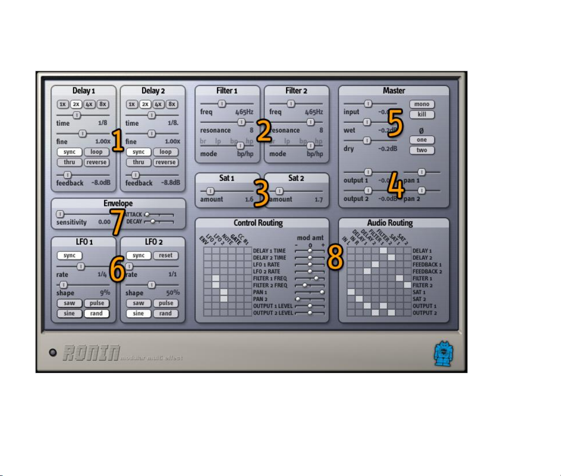
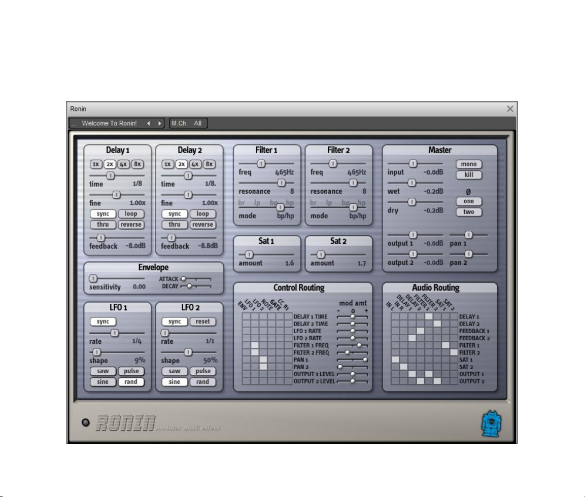
Overview
Here is a picture of Ronin’s editor window, followed by brief descriptions of its modules and their controls:
1. Delays – two delay modules, each up to 12 seconds long, with coarse and fine time controls, looping,
reverse playback, time sync to your VST host’s current tempo, and bypass switches.
9
Page 10

2. Filters – two resonant multi-mode filters, with morphing between low pass, band pass, high pass, and
notch frequency response modes.
3. Saturators – two saturation stages for creating tube-like distortion.
4. Output and Panning – two sets of output level and stereo panning controls.
5. Master Level Controls – gain controls for the input signal and the processed and unprocessed output
signals, switches to mix the input signals to mono and to silence the input signal altogether.
6. LFOs – two low-frequency oscillators for modulating the signal-processing modules, or each other,
with four basic wave shapes, a shape control which warps the wave shapes in different ways, and a
sync button which causes the LFO to follow the tempo of your VST host.
7. Envelope Follower – a modulator that measures the loudness of the incoming sound and generates a
modulation signal for creating effects such as automatic filter sweeps, triggered flanging, and ducked
delays.
8. Routing Matrix – two sets of switching matrixes for connecting the inputs and outputs of all signal -
processing modules, and for connecting the modulators to parameters of the signal-processing
modules.
Each of these modules operates completely independently. For example, you can use one delay module
looping several seconds of audio while using the second delay module to add a slapback echo.
Routing Matrix
Ronin has two arrays of switches, together called the routing matrix, for making connections between audio
modules and modulators. There are two arrays, one for connecting modulators to the audio modules that they
control, and one for connecting audio modules to each other. This is because Ronin treats audio data and
modulation data differently. You cannot use audio data as a source of modulation data, and you cannot listen
to modulation data.
The switch arrays allow the audio modules to be connected to each other in any order or combination. Signals
from one module can be connected to several other modules, and the signals from several modules can be
mixed together and fed to one or more other modules.
10
Page 11

The audio routing matrix is the most dangerous part of Ronin. Because you may patch the audio
inputs or outputs of any module to any other, you can create signal chains that would not be
useful under normal circumstances, such as routing filters back in to themselves, a practice that
will almost certainly result in banshee wails of feedback. If you find that a patch has gotten away
from you, you may hold down the CTRL key on your computer’s keyboard and click on the routing
matrix, and all switches will go to their “off” position, effectively removing the patch entirely.
Amount Controls
Each parameter in Ronin that can be modulated (that is, controlled by a modulator) has a small slider next to
its name in the control routing matrix. This slider is the modulation amount control. It determines how much
the modulator affects the parameter. Thus you can make a modulator affect an audio module only slightly,
such as to create a subtle vibrato by modulating the delay time of one of the delay lines. Or a modulator can
vary a parameter over a wide range, such as creating dramatic timbral sweeps by moving the frequency of a
filter up and down.
The amount controls are also bidirectional, in that moving them to the right makes the modulator increase the
value of the parameter it controls, and moving them to the left make the modulator decrease the value of the
controlled parameter. This affects different parameters in different ways; the detailed descriptions of each
module found later in this manual explain specifically how their amount controls work.
Audio Modules
Ronin is made up of several independent audio-processing modules. Like a modular synthesizer, the
connections between these modules are not permanently fixed. You can connect the modules in any order you
desire. This flexibility presents a wide range of signal processing configurations that aren’t available with other
delay-based plug-ins. The connections between modules are made with a switching matrix similar to the ones
found on EMS analogue synthesizers.
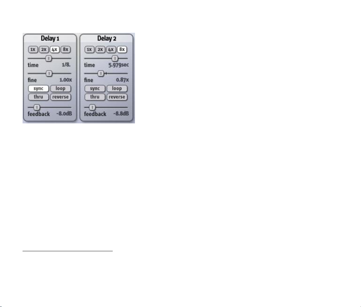
Delays
The two delay modules in Ronin are the main audio processors. The delay modules accurately emulate the
behavior of older digital delays and tape delays, recreating their characteristic interdependence of pitch and
time. If you lengthen the delay time while an audio signal re-circulates in the delay, you will hear its pitch
drop. If you shorten the delay time, the pitch goes up. Most contemporary digital delays—both hardware and
software—do not exhibit this behavior and cannot create the range of weird and wonderful sounds of their
11
Page 12
older counterparts. On the other hand, older digital delays usually had limited dynamic range and undesirable
distortion. Ronin’s delays use 32-bit floating-point samples to create a full-bandwidth, noise-free delay.
Each delay has a maximum delay time of 12 seconds. The delay
times are freely adjustable across their entire range, and can be
locked to the tempo of your VST host sequencer. The delays can be
used as loop recorders, letting you record new audio over a
repeating phrase. The loops can also play backwards, even during
recording. With just one of the two delay modules, you can record a
phrase as a loop, transpose it down an octave by slowing it down to
half its original speed, record a new phrase over the top, turn the
whole loop around and play it backwards, transpose it up by
speeding it up, record another phrase on top, and so on—all in real
time, without stopping. Of course you can also use the delay
modules for all standard delay-based effects such as echo, ping-pong
delay, flanging, chorusing, etc.
There are three main controls in the delay module: Time, Fine, and the multiplier switches. These three
controls together determine the delay time of the module. The Time slider and the multiplier switches can be
thought of as the coarse controls. The range of the time slider is zero1 to a number of seconds equal to the
value of the multiplier switch, which can be one, two, four, or eight. For example, if you set the time slider to
its halfway point and the multiplier switch to 4x, the coarse delay time is two seconds, because half of four is
two seconds.
The Fine slider multiplies the coarse time determined by the settings of the time slider and multiplier
switches. The range of the time fine slider is 0.5 to 1.5. At its halfway setting, its value is 1.0. The total delay
time of the delay module is determined by multiplying the coarse delay time by the value of the time fine
slider. Continuing our example, if you set the time fine slider to its maximum value (1.5), the total delay time
would be three seconds, because two seconds times 1.5 is three seconds.
Usually we don’t think about delay times in terms of seconds and milliseconds when we’re writing music. We
think in terms of rhythmic units, like an eighth note. Ronin can follow the tempo of your VST host sequencer
and automatically calculate delay times to match rhythmic units, thus saving you from having to pull out your
calculator in the middle of a recording session. Simply turn on the Sync switch in the delay module. Now, as
1
Because of the emulation of older delay lines, the minimum delay time is actually not quite zero. It’s a few samples more
than zero, but less than one millisecond.
12
Page 13

you adjust the time slider, you will see that the delay time is show in metrical units. Delay times are
expressed as fractions of a beat, with the assumption that a beat is one quarter of a measure, at the current
tempo of your VST sequencer. Dotted times are represented with the addition of a period (.) in the display,
and triplets are represented by a capital T. For example, a sixteenth-note triplet is shown as 1/16 T in the
display.
The fine slider is not affected by the sync switch and the VST host’s tempo. Its value is still applied after the
delay time is determined by the setting of the time slider, the multiplier switches, and the current tempo. This
means that you can nudge the delay time a little shorter or a little longer than the precise metrical time shown
beneath the slider, so that your delayed audio sits in the groove of your song. This also means that in order
for the value shown in the display to be correct, you must set the time fine slider to its default center position,
so that its value is 1.0. (Most VST hosts let you set a control to its default value by holding down the CTRL key
on your keyboard as you click the control.)
Remember that the two delay modules operate entirely independently, and have independent sync switches.
This can be handy if you want to use one delay for tempo-based delay effects while using the other for short
delay effects such as doubling, chorusing or flanging. For these effects you should set the sync switch to off
since they depend upon short delay times which have no relationship to your song’s tempo. (Of course,
sweeping the delay time of a flanger in sync with your song’s tempo can be a cool effect, which you can
achieve by using Ronin’s LFOs to modulate the delay time, with the LFO’s sync switch turned on. See the
section on LFOs for more information.)
The Feedback slider controls the level of the signal that is fed into the delay line. The delay line has two
inputs: a main input, which has no level-control slider, and a feedback input which has the Feedback levelcontrol slider. Unlike most hardware and software delay processors, the feedback input is not directly
connected to the output of the delay line. You can connect any signal to the feedback input, using Ronin’s
signal switching matrix (described later in this manual). This means that you can connect other modules in the
feedback path of delay, such as a filter to make the delayed signal change in timbre as it circulates thro ugh
the delay. You can also connect the output of one delay module to the feedback input of the other, and viceversa, to create “ping-pong delay” effects that bounce the signal back and forth in the stereo field. Note,
however, that you must connect the feedback input to something with the signal matrix before you’ll hear
anything happen when you turn up the feedback level slider.
The Loop switch makes the delay act as a real-time loop recorder. When you turn on the Loop switch, any
signal that is currently in the delay line will play over and over again, indefinitely (or rather, until you turn off
the Loop switch, turn off the power to your computer, etc.). Any new signal that enters the input of the delay
is overdubbed onto the looped audio, building up layers of sound. You can use the delay time sliders to
change the length of the loop and its playback speed, altering the pitch of the looped audio.
13
Page 14

When the Loop switch is turned on, the feedback input is automatically turned off. This is to make it easier to
switch back and forth between looping and non-looping delay applications. If the feedback input were left on
when the loop was turned on, the audio in the delay line would be added to itself over and over again, rapidly
creating a thick, distorted mess.
The Reverse switch causes the delay line to record and play back in the opposite direction. The effect of the
Reverse switch is slightly different depending on whether or not the Loop switch is turned on. If the Loop
switch is turned on, turning on the Reverse switch causes any audio currently being played in the loop to play
backwards, over and over. You can record new audio over the backwards audio, and then turn the Reverse
switch off to hear the original audio played forwards again and the newly recorded audio played backwards. If
the Loop switch is not turned on, you will hear the audio currently in the delay line played backwards once,
and then all subsequent audio will be played forwards, because the new audio coming into the delay line is
being recorded in the same direction as the audio coming out of the delay line. Yes, this is a little confusing at
first, but it becomes more understandable (and a lot of fun) as you play with it.
The Thru switch bypasses the delay line, sending its input signal directly to its output. The delayed signal is
still sent to the output. This enables you to use the Loop switch to record and loop some audio, then play new
material mixed with the loop, but not added to the loop itself. For example, you can record a phrase in the
loop and then solo over the top of the phrase without adding to the loop by pressing the Thru switch.
Filters
Ronin has two multi-mode filters, modeled after the filters found in analog synthesizers. “Multi-mode” means
that the filters have different response modes: low pass, high pass, band pass, and notch (or band reject). An
unusual feature of Ronin’s filters allows you to “morph” between the different response modes rather than
simply choosing one of the four. The filters have a resonance control and will self-oscillate at high resonance
settings. The two filters operate completely independently and, thanks to Ronin’s signal-routing matrix, can be
combined to create more complex filtering effects.
The main filter control is the frequency slider (whose name is abbreviated to freq in
Ronin’s window). This control sets the center frequency, or cutoff frequency, of the
filter. The filter passes and attenuates signals depending on their frequency relative
to the center frequency, and the mode of the filter, as follows:
Low pass: signals whose frequency is below the center frequency are passed
unmodified, signals whose frequency is above the center frequency are
attenuated.
14
Page 15

High pass: signals whose frequency is above the center frequency are passed unmodified, signals
whose frequency is below the center frequency are attenuated.
Band pass: signals whose frequency is near the center frequency are passed unmodified, signals
whose frequency is further away from the center frequency are attenuated.
Band reject: signals whose frequency is near the center frequency are attenuated, signals whose
frequency is further away from the center frequency are passed unmodified.
The Resonance control causes the response mode of the filter to be sharper or more pronounced. For the low
pass and high pass modes, turning up the resonance emphasizes signals whose frequency is near the center
frequency. In the band pass mode, turning up the resonance narrows the band of frequencies that are passed
without attenuation. In the notch mode turning up the resonance narrows the band of frequencies that are
attenuated. This means, somewhat paradoxically, that the effect of the notch mode is most apparent when
the resonance is turned all the way down, because this makes the notch widest.
Note that a resonant filter has greater than unity gain: it amplifies signals near the center
frequency. This is what creates its unique sonic character, but it can have a tricky consequence
within Ronin. If you set up the signal routing in the signal matrix such that the filter is included
in a feedback loop, the entire loop will eventually start to oscillate and generate extremely loud
signals. If you connect the output of a filter to its own input, or connect the two filters together
so that the outputs of each are sent to the other’s input, you will almost certainly be rewarded by a loud and
potentially piercing noise. Don’t say we didn’t warn you.
The Mode slider sets the frequency response mode of the filter. Rather than clicking between the four modes,
the slider moves freely, providing response modes that are in between two modes. When the indicator mark
points at one of the reference marks on the panel, the filter’s response corresponds to that mode. The modes
are abbreviated on the panel to save space: lp for Low Pass, bp for Band Pass, hp for High Pass, and br for
Band Reject. For example, if you set the slider to halfway between LP and BP, the filter’s response will be a
blend of the low pass and band pass modes, and pass more low-frequency signals than the simple band pass
mode.
Saturators
Ronin’s saturators distort signals that pass through them, somewhat like a guitarist’s distortion pedal or an
overdriven tube pre-amp. The saturators distort the signal by amplifying it and flattening the peaks of the
loud signals using a process known as soft clipping. The saturators have a number of potential uses within
Ronin, such as distorting the original signal to give it a brighter, punchier, and more aggressive sound,
15
Page 16

distorting delayed signals to emulate the less-than-pristine characteristics of older
hardware delays, and distorting signals to increase their harmonic content making
subsequent filtering more noticeable.
The saturators each have a single control that adjusts how much they boost and
distort the signal. If the slider is all the way at the left, the saturators have almost no
effect on the signal passing through them. As you move the slider to the right, the output signal becomes
louder and more distorted.
Because the saturators work in part by amplifying the signal, use them with caution, particularly
if you place them in a feedback loop with other modules. Turning up the saturator’s slider even a
little bit will cause the signals in the feedback loop to grow louder quite rapidly. Also, connecting
the output of a saturator directly to its own input is generally not something that you should do.
(Yes, we realize that you’re now going to try it just because we said that you shouldn’t. You
were probably scolded for running with scissors, weren’t you?)
Output Level and Panning Controls
The Pan and Output sliders in the Master section control the last processing stage that the signal passes
through. Signals connected to Output 1 and Output 2 in the audio switching matrix are directed to this
stage. The output level and panning modules are the last processing stage that the signals pass through
before leaving the plug-in. You can think of this module as a simple two-channel mixer with stereo outputs.
The order in which the other processing modules are connected can be changed freely with the signal matrix,
but the signal always passes through the output and panning module last.
The pan sliders determine the position of the output signal in the stereo field.
Obviously you must use Ronin in a stereo context in your host sequencer for
these sliders to be useful. Ronin uses a special panning algorithm to create a
more interesting sense of spaciousness than a standard equal-power panning
algorithm. (What does that mean? It means that it sounds cool.)
The Output sliders amplify or attenuate the signals. Each has a range of –80dB, which effectively silences all
but the loudest signals, to +3dB, which provides a small amount of boost. Often you will simply leave these
sliders at their default position of 0dB (unity gain), but you can use them to adjust the relative signal levels of
Output 1 and Output 2 when using them to process signals in two different ways.
16
Page 17

Master Input and Output Controls
The input and output sliders provide adjustable amplification and attenuation of the signals as they enter and
leave the plug-in. Each has a range of –80dB, which effectively silences all but the loudest signals, to +3dB,
which provides a small amount of boost. Since Ronin is capable of creating effects with a wide dynamic range,
the input and output controls are helpful for keeping signals within useful levels.
The Input slider adjusts the overall level of the signal arriving at Ronin’s input from your
host sequencer. It affects both the left and right channels equally.
The Wet slider adjusts the level of the signals leaving Ronin. It affects both the left and
right channels equally. This slider is useful for taming Ronin’s occasionally high output
level, and for adjusting the balance of processed and unprocessed signals if you’re using
Ronin as an insert effect.
The Dry slider adjusts the amount of unprocessed signal that is send directly from Ronin’s inputs to its
outputs. If you’re using Ronin as a send effect, you’ll usually want to move this slider all the way to the left,
since the unprocessed signal is already being sent into your mix via its channel strip. On the other hand, if
you’re using Ronin as an insert effect, you’ll usually set this slider to unity gain (0 dB).
If the Mono switch is turned on, the left and right input signals are added together and the summed signal is
used for both the left and right input channels within Ronin. You may find this switch useful if you’re created a
preset intended for stereo processing, and later decide that it would be useful for processing a
mono signal.
The Kill switch, when turned on, silences the input signal altogether. This switch can be used for
fun effects like dub delays, in which only an occasional snare hit or the last word of a vocal line is passed
through the delay. Just turn the Kill switch on, wait for the snare hit, and turn the switch off then back on
again just long enough to let the snare through.
The Kill switch is also useful when using the delays for looping. After turning the loop switch on, turn the Kill
switch on. Now your looped audio will play indefinitely, and incoming audio will not be added to
the loop.
The two Phase switches near the lower right corner of Ronin’s window affect the plug-in’s left
and right input signals as they enter the signal switching matrix. If the Invert switch is turned
on, the corresponding signal is inverted, or given opposite polarity. Inverting a signal can cause
interesting phase-cancellation effects when you mix the signal with the original, after delaying it or processing
it in some other manner.
17
Page 18

Routing Matrix
The signal routing matrix, found on the right in the Routing Matrix section of Ronin’s window, is how you
connect the audio processing modules to each other, and to the plug-in’s inputs and outputs. All of the inputs
and outputs for each audio module are represented in the signal routing matrix. The audio signal from any
module can be connected to the inputs of one or more other modules. Signals from several modules can be
mixed together and connected to one or more other modules.
You can think of signals entering the routing matrix at the top and leaving on
the right. The columns are labeled with the outputs of audio modules, and the
inputs to the plug-in itself. This may seem slightly confusing at first, but
consider that both of these are sources of audio signals within Ronin. The
signal sources are labeled across the top of the matrix as follows, in left to
right order:
IN L, IN R: the left and right inputs to the plug-in. Audio signals coming
from your VST host arrive here. You have to connect at least one of these
signals to something else in the matrix in order to process audio. (Note that
the input signal is also always mixed with Ronin’s output, in an amount controlled by the dry level slider in the
Master Controls section.)
DELAY 1, DELAY 2: the outputs of the two delay modules.
FILTER 1, FILTER 2: the outputs of the two multi-mode filters.
SAT 1, SAT 2: the outputs of the two saturation modules.
The rows in the matrix are labeled with the inputs of audio modules, and the outputs of the plug-in itself.
Again this may seem slightly confusing, but both of these are destinations for audio signals. So by turning on
switches in the matrix, you connect audio sources to audio destinations. The signal destinations are labeled
down the right side of the matrix as follows, in top to bottom order:
DELAY 1, DELAY 2: the inputs of the two delay modules.
FEEDBACK 1, FEEDBACK 2: the feedback inputs of the two delay modules. Signals routed to these
destinations are mixed with signals routed to the DELAY 1 and DELAY 2 destinations, and the mixed signals
enter the delay lines. The levels of the signals routed through the FEEDBACK inputs are controlled by the
Feedback sliders.
18
Page 19

FILTER 1, FILTER 2: the inputs of the two multi-mode filters.
SAT 1, SAT 2: the inputs of the two saturation modules.
OUTPUT 1, OUTPUT 2: the outputs of the plug-in. Audio signals routed to these destinations are sent to your
VST host, after passing through the output level and panning controls. You must connect something to these
destinations in order to hear the audio processed by Ronin. Note that the OUTPUT 1 and OUTPUT 2 signal
destinations are independent and not directly associated with the left and right output channels of the plug-in.
If a Ronin patch does true stereo processing, usually the OUTPUT 1 signal will be assigned to the plug-in’s
left output by turning its pan slider all the way to the left, and the OUTPUT 2 signal will be assigned to the
right output by turning its pan slider all the way to the right.
To make a connection in the matrix, click at the intersection of the source and destination that you wish to
connect. A white square indicates that a connection is made between the source and destination. Click again
on the dot to remove a connection. Hold down the CTRL key on your keyboard and click anywhere in the matrix
to remove all of the connections at once.
Modulators
Like a modular synthesizer, Ronin has a number of modulators, that is, modules that affect the behavior of
other modules. A modulator alters one or more parameters of the audio-processing modules, or of other
modulators. For example, a low-frequency oscillator (LFO) modulator can be used to modulate (change) the
delay time of a short delay line to create a chorusing or flanging effect, or to vary the frequency of a filter to
create a synthesizer-like timbre sweep. Ronin’s modulators are connected to its audio modules with a
switching matrix.
Also, all of Ronin’s controls can be assigned to MIDI continuous controllers, so that you can adjust them
directly with knobs or sliders on your MIDI keyboard.
LFOs
Ronin has two low-frequency oscillators (LFOs) which generate modulation signals that repeat over time. They
have a variety of potential uses, such as varying the delay time of a delay processor slightly to create a
flanging or chorusing effect, varying the cutoff frequency of a filter to create a wah-wah effect, or controlling
the output level and panning parameters to create tremolo, auto-panning, or rhythmic gating effects. The
LFOs can be locked to the tempo of your VST host for creating rhythmic effects that fit with the groove of your
music, or can run freely and independently.
19
Page 20

The Rate slider determines how fast the output of the LFO varies
over time. If the sync button is not turned on, the LFO’s rate can be
varied from one cycle every 100 seconds (that is 0.01 cycles per
second, abbreviated 0.01 Hz) to ten cycles every second (10 Hz).
The Shape slider and buttons work together to control how the
LFO’s output varies over time. The buttons let you choose one of
four waveforms, with triangular, rectangular, sinusoidal, and
randomly determined shapes. The Shape slider changes the basic
waveform in different ways, depending on which waveform is chosen
with the buttons.
If the saw wave is selected, and the Shape slider is set to the middle of its range, the output of the LFO
rises and falls evenly between its lowest and highest values, creating a symmetric triangular wave. If you
rotate the Shape slider to the left, the LFO output rises more quickly and falls more slowly, creating what
is often called a sawtooth wave. If you rotate the Shape slider to the right, the LFO rises more slowly and
falls more quickly, creating what is called a ramp wave.
If the pulse wave is selected, and the Shape slider is set to the middle of its range, the output of the LFO
jumps between its lowest and highest values, staying for an equal period of time at both values. If you
rotate the Shape slider to the left, the output stays at its highest value for a shorter period of time. If you
rotate the Shape slider to the right, the output stays at lowest value for a shorter period of time. In
engineering terms, the Shape slider varies the duty cycle of the rectangular wave.
If the sine wave is selected, and the Shape slider is set to the middle of its range, the output of the LFO
varies smoothly between its lowest and highest values. The difference between a sine wave and a triangle
wave is that the triangle wave abruptly changes direction when it reaches its highest and lowest values;
whereas the sine wave gradually slows down, stops, and speeds up again when it changes directions.
Turning the Shape slider warps and skews the sine wave without creating any sharp corners in its shape.
Its effect is far easier to hear than to describe.
If the random wave is selected, and the Shape slider is turned all the way to the left, the output of the
LFO jumps to a random value, changing at a rate determined by the rate slider. As you rotate the Shape
slider to the right, the output moves more slowly from one random value to the next.
The following diagram illustrates the different modulation signals generated by different settings of the shape
and wave controls:
20
Page 21

Note that the output of the LFO is bipolar, that is, it varies above and below zero. When you use an LFO to
modulate a parameter, the parameter will change up and down relative to the value that you set with its
slider.
If the Sync button is turned on, the LFO’s rate is determined by the tempo of your music as reported by your
VST host sequencer. A value of 1/1 represents a whole note, a value of 1/8 represents an eighth note, and so
on. Dotted notes, which have a duration equal to one and a half times a regular note, are shown with a period
in the display. For example “1/4.” is displayed to indicate a dotted quarter note, which has a duration of a
quarter note plus an eighth note. Triplets, which are groups of three notes that have the same duration as two
21
Page 22

regular notes, are shown with a T in the display. “1/16T” represents a duration equal to 2/3 that of a sixteenth
note.
If LFO 2’s Reset switch is turned on, the second LFO always resets to the beginning of its cycle when the first
LFO starts its cycle. This switch has no effect if the Sync switch is turned on.
Envelope Follower
The envelope follower generates a modulation signal by measuring the amplitude (or loudness) of the signal
arriving at the plug-in’s inputs. The envelope follower always measures the two input signals added together,
regardless of any connections made in the signal matrix.
The envelope follower has three controls which determine how it responds to the incoming signal:
The Sensitivity slider (labeled S) adjusts the envelope follower’s
overall sensitivity to the input signal. Essentially it acts like a gain
control for the envelope follower. If the modulation signal
generated by the envelope follower is too weak, raise the
Sensitivity slider.
The Attack slider (labeled A) adjusts how quickly the envelope follower responds to increases in the incoming
signal’s level. If the Attack slider is at the left of its range, the envelope follower’s output jumps almost
instantly in response to increases in the input signal’s level. As you move the Attack slider to the right, the
envelope follower reacts more slowly to signal-level increases. The Attack slider is useful for making the
envelope follower’s output smoother when the input signal contains sharp transients, such as drum sounds.
The Decay slider (labeled D) adjusts how quickly the envelope follower’s output decreases as the incoming
signal’s level decreases. If the Decay slider is at the left of its range, the envelope follower’s output drops
almost immediately when the input signal’s level decreases. As you move the Decay slider to the right, the
envelope follower reacts more slowly to signal-level decreases. The Decay slider is useful for stretching the
envelope follower’s output, making it fade away more slowly than the input signal.
Note that unlike the LFOs, the envelope follower’s output is not bipolar. Its output is never less than zero, so it
always acts to increase the parameters that it modulates.
22
Page 23

MIDI
Data from your MIDI keyboard or other MIDI controllers can be used as a modulator in several ways, enabling
Ronin’s effects to respond dynamically as you play.
One modulation signal is generated from MIDI note numbers received by Ronin. If you play middle C (MIDI
note number 64) on your keyboard, a modulation value of zero is generated. As you play up the keyboard
from middle C, the modulation value increases. If you play C one octave above middle C, the modulation
value is +1. If you play below middle C, the modulation value becomes negative. Playing C below middle C
generates a modulation value of -1. The modulation values, like all modulation values in Ronin, do not go
above or below +1 or -1, even if you play outside of the two-octave range centered on middle C.
Another modulation signal, similar to the gate signal found in analog synthesizers, is generated from MIDI
note messages. Normally this modulation signal has a value of zero. When you press any key on your MIDI
keyboard, the gate modulation signal becomes +1. If you play additional keys while still holding the first key,
the gate signal stays at +1. After you release all of the keys, the gate signal returns to zero.
A third modulation signal is generated from MIDI continuous controller messages. This modulation signal
responds to messages from MIDI continuous controller #1, which is the message usually sent by the
modulation control (or “mod wheel”) found on most MIDI keyboards. The modulation value is generated
directly from the data value sent by the controller. When the value of this controller message is zero, the
modulation signal is also zero. As the controller data value increases (e.g., as you push the mod wheel
forward), Ronin’s modulation value increases. When the controller value reaches 127, the modulation value
becomes +1.
These modulation signals are used within Ronin’s modulation routing matrix to modulate the parameters of
the audio modules. You can also control any of Ronin’s parameters with MIDI controllers by using the MIDI
Learn mode, which is described later in this manual.
Routing Matrix
The control routing matrix, found on the left in the Routing Matrix section of Ronin’s window, lets you connect
the output of the modulators to modulation destinations. Most modulation destinations affect parameters in
the audio modules, but the rates of the LFOs can also be modulated. All of the modulation signal sources and
all of the modulation destinations are represented in the modulation routing matrix. Any modulation signal can
be connected to one or more modulation destinations. Modulation signals from several sources can be mixed
together and connected to one or more destinations.
23
Page 24

You can think of signals entering the routing matrix at the top and leaving on the right. The columns are
labeled with the names of modulation sources, and the rows are labeled with the names of modulation
destinations. The sources are labeled across the top of the matrix as follows, in left to right order:
ENV: the output of the envelope follower.
LFO1, LFO2: the outputs of the two low-frequency oscillators.
NOTE: the modulation signal generated from MIDI note
numbers, in proportion to their pitch.
GATE: the modulation signal which is +1 when any MIDI notes
are played, and zero after all notes are released.
CC#1: the modulation signal generated from MIDI continuous
controller messages for controller #1.
The rows in the matrix are labeled with modulation
destinations, that is, parameters that can be affected by
modulators. The modulation destinations are labeled down the right side of the matrix as follows, in top to
bottom order:
DELAY 1 TIME, DELAY 2 TIME: the delay times of the two delay modules. Modulation signals connected to
this destination are added to the current position of the delay’s Fine slider. Use this destination to create
effects such as flanging or chorusing by connecting it to an LFO.
LFO 1 RATE, LFO 2 RATE: the rates of the two low-frequency oscillators. Modulation signals connected to
this destination are added to the current position of the LFO’s Rate slider. Use this destination to make the
LFOs speed up as you move the mod wheel on your MIDI keyboard. Or, borrowing an old trick used on
modular analog synthesizers, connect an LFO’s output to its own rate modulation destination to create
different wave shapes.
FILTER 1 FREQ, FILTER 2 FREQ: the frequencies of the two filters. Modulation signals connected to this
destination are added to the current position of the filter’s Freq slider. Use this destination to create
synthesizer-like filter-sweep effects.
24
Page 25

PAN 1, PAN 2: the stereo panning position of the two output signals. Modulation signals connected to these
destinations are added to the current position of the Pan sliders in the Master Controls section. Use this
destination to make Ronin’s output move around in the stereo field.
OUTPUT 1 LEVEL, OUTPUT 2 LEVEL: the loudness level of the two output signals. Modulation signals
connected to these destinations are added to the current position of the Output sliders in the Master section.
Use this destination to create tremolo effects with an LFO, or ducked-delay effects with the envelope follower.
Want to simply gate audio by playing a note on your keyboard to create transformer effects? Use the MIDI
gate modulation source and this modulation destination.
To make a connection in the matrix, click at the intersection of the source and destination that you wish to
connect. A white square indicates that a connection is made between the source and destination. Click again
on the dot to remove a connection. Hold down the CTRL key on your keyboard and click anywhere in the matrix
to remove all of the connections at once.
Depth Controls
Each modulation destination—that is, each parameter that can be modulated—has a modulation depth control.
The modulation depth controls are the small sliders to the right of the destination names in the Control
Routing matrix. These sliders determine how much the modulation signals affect the parameter. If the depth
control is at its center position (which is its default position), the modulation signal has no effect on the
parameter. Regardless of which modulation signals you connect to this destination in the modulation switch
matrix, the parameter will not respond to these signals if the depth control is at its center position. As you
move the depth slider to the right, the modulation signal has an increasing effect on the parameter. If you
move the slider only slightly above its center position, you will hear only a small change in the parameter as it
responds to the modulation signal. A small amount of modulation is useful for effects that require only small
changes in parameter values, such as varying the delay time in a flanger. If you move the slider to the far
right of its range, you will hear the parameter change over a wide range in response to the modulation signal.
Large amounts of modulation are useful for complete changes in parameter values, such as panning a signal
all the way from one side of the stereo field to the other or sweeping a filter’s frequency from completely
closed to completely open.
If you move a depth control’s slider downwards from its center position, the modulation signal is inverted
before affecting the parameter. As you move the slider to the left, the modulation signal has a greater effect
on the parameter—but in the opposite direction than if you move the slider to the right. For example, suppose
the envelope follower is connected to one of the filter’s frequency controls, and the frequency control’s depth
control is moved upward from its center position. The filter frequency will increase when the incoming signal
becomes louder, because the envelope follower generates a positive modulation signal that is proportional to
25
Page 26

the loudness of the incoming signal. (Controlling a filter with an envelope follower in this manner is often
called an “auto-wah” effect.) If you move the depth control below its center position, the filter frequency will
decrease when the incoming signal becomes louder, because the modulation signal coming from the envelope
follower is inverted before it is applied to the frequency parameter.
Things become more complicated when using bipolar modulation sources, such as the LFOs. Since these
modulation signals vary above and below zero, they increase and decrease the value of the parameters that
they modulate. If you connect an LFO to a filter, and move the depth control slider to the right, you will hear
the filter’s frequency vary above and below the frequency set with its Freq slider. If you move the depth slider
to the left, you will still hear the frequency vary above and below the value set with the Freq slider, because
although the modulation signal is now inverted, it is still bipolar. However, if you connect the same LFO to
both of Ronin’s filters, move one filter’s modulation depth slider to the right of its center position, and move
the other filter’s slider left of the center position, you will hear one filter’s frequency go up while the other one
goes down, and vice versa. The inverted modulation signal causes the filter’s frequency to move in the
direction opposite the other filter’s frequency.
Note that you can hold down the SHIFT key on your computer’s keyboard while moving the depth sliders to
make finer adjustments. This works for any of the sliders in Ronin’s window.
MIDI Controllers
Ronin responds to MIDI continuous controller messages. You can use hardware MIDI controllers, such as MIDI
slider boxes or the knobs found on some MIDI keyboards, to adjust Ronin’s parameters. Every control in
Ronin’s user interface can be manipulated with a MIDI controller, except the switches in the routing matrixes.
Ronin’s delay times, filter frequencies, output levels, and so on can all be placed under the control of your
MIDI hardware.
Ronin has a simple “MIDI Learn” mode for assigning its parameters to MIDI controllers. To assign a parameter
to a MIDI controller:
1. Hold down the SHIFT and CTRL keys (SHIFT and CMD keys on a Mac) on your computer’s keyboard, and
click once on the parameter’s control. A blue box will be drawn around the control to indicate that it is
ready to learn which MIDI controller it will be assigned to.
2. Move the MIDI controller to send a continuous controller message—turn the knob, press the button,
move the slider, whatever is appropriate.
26
Page 27

3. The blue square will disappear. Now Ronin’s control will move when you manipulate the MIDI
controller.
Ronin waits until it has received two consecutive continuous controller messages with the same controller
number before it makes an assignment. This filters out extraneous data sent by some MIDI controllers. If you
are assigning a button or switch on a MIDI controller, you may have to press or move the switch twice before
Ronin recognizes the controller and assigns it to the desired parameter.
To assign a different MIDI controller to a control, repeat the same procedure.
To cancel MIDI Learn mode without assigning a controller, hold down the SHIFT and CTRL keys (SHIFT
and CMD keys on a Mac) and click in any empty area in Ronin’s window (i.e. , don’t click on another
control).
To remove a MIDI controller assignment from a control, SHIFT and CTRL keys, (SHIFT and CMD keys on a
Mac) click on the control once so that the orange box appears, then click again on the same control.
Ronin’s MIDI controller assignments are stored with the plug-in’s preset data. If you use MIDI controllers
frequently, you may find it helpful to store a template preset that contains the controller assignments that you
usually use. Use this template preset as a starting point when making new presets so that you do not have to
reassign the MIDI controllers every time.
The Audio Unit version of Ronin does not provide the same MIDI assignment features as the VST version.
Almost all Audio Unit hosts provide their own mechanism for assigning MIDI controllers to parameters, so it
would be redundant to implement MIDI controller assignments in the plug-in itself. Consult the documentation
for your Audio Unit host to learn how to use its MIDI features.
Automation
All of Ronin’s controls, except for the routing matrix switches, can be automated using your host's automation
features. Consult your host's documentation for information on how to use these features.
27
Page 28

Putting It All Together: Some Examples
Here are detailed descriptions of four of Ronin’s presets, which you will find near the bottom of the preset list.
These descriptions illustrate some of the techniques you will use to create your own effects with Ronin. Place
Ronin as an insert effect on a channel in your VST host, then load the presets as you read about them here.
[ This space intentionally left blank ]
[ don’t you wonder sometimes why people print that on otherwise blank pages? ]
28
Page 29

Stereo Delay with Cross Feedback and Filtering
This preset demonstrates Ronin’s ability to set its delay times based on your VST host’s current tempo, and
how to use the signal matrix for creating filtered delay and stereo delay effects.
Look first at the Routing Matrix section. There are no connections in the modulation matrix, so the LFOs,
envelope follower, and MIDI have no effect. In the signal matrix, you can see that the left and right inputs are
connected to the first and second delay modules, respectively. Each delay’s output is connected to a filter’s
input, and the filters are connected to the plug-in’s two output channels. Hence signals pass first through the
delays, then the filters, then out of the plug-in. Since we’re using separate delays and filters for each channel,
this is a “true stereo” processing configuration.
29
Page 30

Also notice that we’ve connected the output of delay 1 to the feedback input of delay 2, and vice versa. This
means that signals emerging from one channel’s delay will be sent to the input of the other channel’s delay,
which will cause the delayed signals to bounce back and forth in the stereo field. Of course, in order for this to
work, we have to pan the outputs of the plug-in to the left and right sides of the stereo field, which you can
see we’ve done by looking at the Pan controls in the Master Controls section. We’ve also set the Wet and Dry
output level controls to the same value, so that the delayed signal will be as loud as the original signal. (If you
want to use this preset as a send effect, move the Dry slider all the way to the left.)
We’ve turned on both of the Sync switches for the delays, so the delay times will be calculated to match the
VST host’s tempo automatically. The delay times are set to an eighth note and a quarter note. The feedback
sliders are set to moderate levels so that the delayed signals will fade out after a few repeats.
Try playing a drum loop or other strongly rhythmic audio phrase through Ronin. You’ll hear the delayed audio
playing in time, and bouncing back and forth between the stereo channels as it decays. Also notice that the
delayed signals sound a little darker than the original signal. This is because the delayed signals pass through
the filters before leaving the plug-in. The filters are set to their low-pass mode, with a cutoff frequency of
about 8kHz. This setting filters out the higher frequencies of the signal. Filtering the delayed signal make it
“sit behind” the original signal in the output of the plug-in.
30
Page 31

Filtered Auto-Panning
This preset doesn’t use Ronin’s delays or panning controls at all. Instead it uses filters modulated by the LFOs
to create a swirling effect.
As you can see by looking at the signal matrix, the signal connections are simple: the left and right input
channels are connected to filters 1 and 2, and the filters are connected to their corresponding output
channels. We’ve turned on the Mono switch in the Master Controls section so that if the input signal is stereo,
its two channels are added together. We did this because this patch uses modulated panning to create a sense
of stereo movement. Also, we move the Dry input level control all the to the left, so that only the processed
signal is heard. You might want to try turning this control up to mix in some of the original signal.
31
Page 32

The connections in the modulation matrix are a little more complicated. LFOs 1 and 2 are connected so that
they modulate the frequencies of the filters. Notice that the depth controls for both filters are moved to their
far right position, so that the LFOs create large changes in the frequencies of the filters. The LFOs are also
connected to the two Pan modulation destinations. The Pan controls are at their center positions, but their
depth controls are also at the far right. Since the LFOs are bipolar, their modulation signals will cause the
plug-in’s output signals to move back and forth in the stereo field.
Finally, the output of LFO 1 is connected to the rate modulation destination of LFO 2, and vice versa. The
depth controls for these two parameters are turned up only slightly. Connecting the LFOs to each other in this
manner causes both of their outputs to vary in an unpredictable manner, making the effects of their
modulation more interesting (or at least less predictable).
Try running a signal with a wide range of frequencies, such as a bright synthesizer pad or a guitar sound,
through Ronin. You’ll hear the output signal get brighter and darker, and move around, as the LFOs change
the frequencies of the filters and the pan positions of the outputs.
The filters are set to their low-pass modes, with the resonance controls turned up somewhat. This gives them
a familiar “synthesizer-like” sound. Try moving the Mode sliders to their other positions to hear the effects of
the different response modes. The Bandpass mode can be particularly effective in this preset.
If you want to make the panning and filtering move in time with your song’s tempo, turn on the Sync switches
for both LFOs, and turn off the connections to the LFO rate modulation destinations in the modulation matrix.
32
Page 33

Ducked Delays
“Ducking” is the process of lowering the loudness of one signal in response to the loudness of another signal.
For example, ducking is used in radio broadcasts to lower the volume of the music while the DJ talks. In this
preset, we use ducking to lower the volume of the output of delays so that the delay effect is not heard until
after you stop playing.
The signal matrix has a straightforward stereo-delay patch: the left and right inputs are connected to delays 1
and 2, and the delays are connected to their corresponding outputs. The outputs of the delays are also fed
back into their inputs. The feedback levels are set high enough so that the delayed signals will repeat several
times as they fade out.
33
Page 34

The Wet and Dry level controls are set to the same value so that the delayed signals are as loud as the
original signal. The Pan positions are set to the left and right to give the delayed signals balanced stereo
placement without extreme panning.
Here’s the tricky part: the output of the envelope follower is connected to both output Level modulation
destinations. The depth controls for both of these destinations are at their lowermost positions. This means
that the modulation signal from the envelope generator is inverted before being applied to the output levels,
which means that as the input signal gets louder, the output levels will be decreased.
Set up your host program to play a few bars of a drum pattern or other fairly dense musical passage through
Ronin. As the music plays you will hear little if any delayed signal. When the input signal stops, you’ll hear the
delayed signal fade in. The length of time it takes for the delayed signal to fade in is determined by the
envelope follower’s decal slider. Try lowering the slider to hear the delayed signal fade in more rapidly.
34
Page 35

Fun With Looping
This preset will introduce you to some of the fun things you can do with Ronin’s looping delays. You’ll need a
synthesizer, guitar, microphone, or some other way of getting audio into your VST host in real time to follow
our explanation.
Look at the signal matrix. The left input is connected to delay 1, but we’ve turned on the Mono switch in the
Master section so both input channels are sent to delay 1. (This is simply to make it easier for you to connect
a signal to the plug-in within your VST host.) The output of delay 1 is connected to the plug-in’s first output
channel, and also to delay 2. Delay 2 is connected to the second output channel.
35
Page 36

Delay 1 is set up for interactive looping. The Sync switch is on so that the length of the loop is determined by
your sequencer’s tempo, which should be set to some moderate value like 120bpm. The Loop switch is turned
on so that audio recorded in the loop will play indefinitely.
Delay 2 is set to a very short delay time. Outputs 1 and 2 are panned slightly left and right. This creates a
stereo chorusing effect, since the left and right outputs of the plug-in are delayed slightly with respect to each
other. We use both LFOs to modulate the delay time of delay 2, to add motion to the chorus effect. The LFOs
are set to different frequencies and somewhat different wave shapes. Mixing both LFOs together makes the
chorus effect less repetitive.
Play a short phrase on your instrument (or say something into your mic). You’ll hear the audio playing over
and over. If you don’t like what you hear, turn the Loop switch off, wait ‘til the last repetition of the loop has
played, then turn it back on.
Turn delay 1’s Fine slider all the way counter-clockwise. You’ll hear the loop slow down to half its original
speed, playing one octave lower. Turn on the Reverse switch. You’ll hear the loop playing backwards, still one
octave lower.
Play another phrase. The new phrase will be overdubbed on the loop.
Hold down the CTRL key on your computer’s keyboard and click the Fine slider to return it to its default, center
position. Now you’ll hear the first phrase playing at its original speed and pitch, but still backwards, and the
new phrase playing at twice its original speed and pitch.
Click the Reverse button. Now you’ll hear the first phrase as you originally recorded it, and the new phrase
playing backwards at twice its original speed and pitch.
Repeat as desired. We used only one of the two delays for looping, and used the second one to create a
chorus effect just for the sake of illustration. Of course you can use both delays for looping, building up a new
phrase in one while the other continues to loop.
36
Page 37

And Finally…
Thanks again for purchasing Ronin. We make every effort to ensure your satisfaction with our products, and
want you to be happy with your purchase. Please write info@audiodamage.com if you have any questions or
comments.
37
 Loading...