

Audio RA101 Product Manual

Product Instruction and
Installation Manual

Table of Contents
Introduction. . . . . . . . . . . . . . . . . . . . . . . . . . . . . . . . . . . . . . . . . . . 3
CE Declaration . . . . . . . . . . . . . . . . . . . . . . . . . . . . . . . . . . . . . . . . 4
Safety Instructions. . . . . . . . . . . . . . . . . . . . . . . . . . . . . . . . . . . 5-6
Explanation of Symbols. . . . . . . . . . . . . . . . . . . . . . . . . . . . . . . . 6
RA101 Single Channel Receiver Amplier. . . . . . . . . . . . . 7-8
IR-2007. . . . . . . . . . . . . . . . . . . . . . . . . . . . . . . . . . . . . . . . . . . . . 9-10
Achiever Operating Controls . . . . . . . . . . . . . . . . . . . . . . . 11-12
Elite II . . . . . . . . . . . . . . . . . . . . . . . . . . . . . . . . . . . . . . . . . . . . . 13-14
Ultimate IISE Operating Controls . . . . . . . . . . . . . . . . . . . 15-16
Function Button . . . . . . . . . . . . . . . . . . . . . . . . . . . . . . . . . . . . . . 17
Innovator Operating Controls. . . . . . . . . . . . . . . . . . . . . . 18-19
Student Microphone Operating Controls . . . . . . . . . . . . . . 20
Teacher Microphone Operating Controls . . . . . . . . . . . . . . 21
Charging the Battery in the Microphones. . . . . . . . . . . . . . 22
SoloSolution Operating Controls. . . . . . . . . . . . . . . . . . . . . . 23
EDS-07 IR Dome Sensor Operating Controls . . . . . . . . . . . 24
AE-DCF Dome Sensor Coupler . . . . . . . . . . . . . . . . . . . . . . . . 25
Operating Procedure . . . . . . . . . . . . . . . . . . . . . . . . . . . . . . . . . 26
Remote Volume Control . . . . . . . . . . . . . . . . . . . . . . . . . . . . . . 27
Using the Microphones as a Transmitter. . . . . . . . . . . . . . . 28
Setting the Aux Mute . . . . . . . . . . . . . . . . . . . . . . . . . . . . . . 29-33
Wiring Connections and Installation. . . . . . . . . . . . . . . . 33-44
EDS-07 Dome Sensor Wiring and Placement. . . . . . . . 34-35
External Control . . . . . . . . . . . . . . . . . . . . . . . . . . . . . . . . . . . . . . 45
Precautions for Installation. . . . . . . . . . . . . . . . . . . . . . . . . . . . 46
Installing the Bracket . . . . . . . . . . . . . . . . . . . . . . . . . . . . . . 47-50
Fuse Part Numbers . . . . . . . . . . . . . . . . . . . . . . . . . . . . . . . . . . . 51
Teachers Checklist . . . . . . . . . . . . . . . . . . . . . . . . . . . . . . . . . . . . 52
Troubleshooting. . . . . . . . . . . . . . . . . . . . . . . . . . . . . . . . . . . 53-54
Power Cords for Great Britain . . . . . . . . . . . . . . . . . . . . . . . . . 55
Safety Instructions for Great Britain . . . . . . . . . . . . . . . . 56-57
WEEE Fitting. . . . . . . . . . . . . . . . . . . . . . . . . . . . . . . . . . . . . . . . . . 58
Warranty . . . . . . . . . . . . . . . . . . . . . . . . . . . . . . . . . . . . . . . . . . . . . 59
2

Introduction
AUDIO ENHANCEMENT has been creating
technologically advanced products that
exceed expectations for over 25 years.
Designed by caring professionals for those
who teach the future leaders of America,
your infrared (IR) classroom amplication
system is an important step in improving the
learning environment.
Your infrared classroom system represents
a breakthrough in classroom amplication.
It assures you the clarity and interference
free performance you expect, even with
large numbers of systems at use in the same
building.
Please read through this manual before
installing and using your IR system, and refer
to it often. Our sta is available to answer
any questions that may arise at 1-800-383-
9362.
When asked to rank the importance of nine dierent types of equipment used in classroom instruction,
• 34% of teachers in general education ranked classroom amplication most important. This
ranks it above the overhead projector, which came in second at 18%, and the computer at 16%.
• 75% of a child’s school day is spent engaged in listening activities.
• 90% of a young child’s knowledge is attributed to incidental reception of a conversation around
(3)
(2)
(1)
them.
1. Allen, L. (1993). Promoting the usefulness of classroom amplication equipment. Educational Audiology Monograph 3, 32-34.
2. Flexer, Carol (2002) Univeristy of Akron
3. Flexer, Carol (1993). “Classroom Management of Children with Hearing Loss: Preferential Seating is NOT enough” presentation. San Francisco,
CA 8/14/93.
3

CE Declaration
English
We declare under our sole responsibility that the product to which this declaration relates is in conformity
with the standards or other normative documents following the provisions of Directives 2006/95/EC and
2004/108/EC.
Deutsch (German)
Wir erklären in alleiniger Verantwortung, daß das Produkt, auf das sich diese Erklärung bezieht, mit der
folgenden Normen oder normativen Dokumenten übereinstimmt. Gemäß den Bestimmungen der Richtlinie
2006/95/EC und 2004/108/EC.
Français (French)
Nous déclarons sous note seule responsabilité que le produit auquel se rèfére las présente déclaration
est conforme aux normes ou autres documents normatifs conformé ment aux dispositions des directives
2006/95/EC et 2004/108/EC.
Español (Spanish)
Nosotros declaramos bajo nuestra única responsabilidad que el producto a que hace referencia esta
declaración está conforme con las normas u otros documentos normativos siguiendo las estipulaciones de
las directivas 2006/95/CE y 2004/108/CE.
Italiano (Italian)
Noi dichiariamo sotto nostra esclusiva responsabilità che il prodotto a cui si riferisce la presente dichiarazione
risulta confrome ai seguenti standard o altri documenti normativi confromi alle disposizioni delle direttive
2006/95/CE e 2004/108/CE.
Nederlands (Dutch)
Wij verklaren als enige aansprakelijke, dat het product waarop deze verklaring betrekking heeft, voldoet aan
de volgende normen of andere normatieve documenten, overeenkomstig de bepalingen van Richtlijnen
2006/95/EC en 2004/108/EC.
Dansk (Danish)
Vi erklærer os eneansvarlige for, at dette produkt, som denne deklaration omhandler, er i overensstemmelse
med standarder eller andre normative dokumenter i følge bestemmelserne i direktivene 2006/95/EC og
2004/108/EC.
Svenskt (Swedish)
Vi deklarerar härmed värt fulla ansvar för att den produkt till vilken denna deklaration hänvisar är i
överensstämmelse med standarddokument, eller andra normativa dokument som framställs i direktiv nr.
2006/95/EC och 2004/108/EC.
Suomi (Finnish)
Ilmoitamme yksinomaisella vastuullamme, että tuote, jota tämä ilmoitus koskee, noudattaa seuraavia
standardeja tai muita ohjeellisia asiakirjoja, jotka noudattavat direktiivien 2006/95/EC ja 2004/108/EC
säädöksiä.
Norske (Norwegian)
Vi erklærer oss alene ansvarlige for at produktet som denne erklaeringen gjelder for, er i overensstemmelse
med følgende normer eller andre normgivende dokumenter som følger bestemmelsene i direktivene
2006/95/EC og 2004/108/EC.
4

Safety Instructions
1. Read these instructions.
2. Keep these instructions.
3. Heed all warnings.
4. Follow all instructions.
5. Do not use this apparatus near water.
6. Clean only with dry cloth.
7. Do not block any ventilation openings. Install in accordance with the manufacturer’s
instructions.
8. Do not use near any heat sources such as radiators, heat registers, stoves, or other apparatus
(including ampliers that produce heat).
9. A polarized plug has two blades, one wider than the other. A grounding-type plug has two
blades and a third grounding prong. Removing it will defeat the purpose of the polarized
or grounding-type plug. The wide blade or the third prong is provided for your safety. If the
provided plug does not t into your outlet, consult an electrician for replacement of the old
outlet.
10. Protect the power cord from being walked on or pinched, particularly at plugs, convenience
receptacles, and the points where it exits from the apparatus.
11. Only use attachments/accessories specied by the manufacturer.
S3125A
12. Use only with the cart, stand, tripod, bracket, or table specied by the manufacturer or
sold with the apparatus. When a cart is used, use caution when moving the cart/apparatus
combination to avoid injury from tip-overs.
13. Unplug this apparatus during lightning storms or when unused for long periods of time.
14. Refer all servicing to qualied service personnel. Servicing is required when the apparatus
has been damaged in any way. Examples include:
• Power-supply cord or plug is damaged
• Liquid has been spilled or objects have fallen into the apparatus
• Apparatus has been exposed to rain or moisture
• Apparatus does not operate normally
• Apparatus has been dropped
5
WARNING:
• This apparatus must be grounded.
• Apparatus shall be connected to a main socket outlet with a protective grounding
connection.
• The main plug or appliance coupler shall remain readily operable.
• To prevent re or electric shock hazard, do not expose this apparatus to rain or moisture.
• The apparatus should not be exposed to dripping, splashing, or objects lled with liquids.
Be sure not to place containers lled with liquid on the apparatus.
• All work related to the installation of this product should be performed by qualied service
personnel or system installers.
• For PERMANENTLY CONNECTED APPARATUS provided without an all-pole MAINS SWITCH
or an all-pole circuit breaker, the installation shall be carried out in accordance with all
applicable installation rules.
• The connections should comply with local electrical code.
CAUTION:
• Before attempting to connect or operate this product, please read the label on the
bottom of the apparatus.
CAUTION
RISK OF ELECTRIC SHOCK
DO NOT OPEN
CAUTION: TO REDUCE THE RISK OF ELECTRIC SHOCK,
DO NOT REMOVE COVER (OR BACK). NO USERSERVICEABLE PARTS INSIDE. REFER SERVICING TO
QUALIFIED SERVICE PERSONNEL.
The lightning ash with
arrowhead symbol within an
equilateral triangle is intended to
alert the user to the presence of
uninsulated dangerous voltage
within the product’s enclosure
that may be of sucient
magnitude to constitute a risk of
electric shock to persons.
Explanation of Symbols
220 - 240 VAC
50 to 60 Hz
The exclamation point within an
equilateral triangle is intended
to alert the user to the presence
of important operating and
maintenance (servicing) instructions in the literature
accompanying the appliance.
A.C. Power Only
Rated Mains Frequency
The date or dating code should not exceed any three consecutive months of manufacture. The
dating code shall be in an established alphanumeric code armed by the manufacturer. The
coding system shall have a minimum 10-year repetition cycle.
6

Operating Controls
RA101
2
1
1. Power Switch: Turn the power of the main unit and the infrared sensor (accessory) ON/OFF.
2. Power Indicator (green) [POWER]: When the power switch is turned on, the power
indicator is illuminated in green.
3. Feedback Blocker Indicator (orange) [FEEDBACK BLOCKER]: The orange LED (Light
Emitting Diode) will light up when the feedback blocker is activated.
3
5
4
6
4. Microphone Level Control Knob: Adjust the volume of the infrared microphone.
5. Infrared Signal Indicator (green) [IR SIGNAL]: Reception indicator is illuminated in
green when an infrared signal from the microphone is received.
6. Line Level Control Knob [LINE]: Adjust the volume of external audio device connected
to the line input terminal on the rear panel.
AC Adapter: Use the “3A-621DA24” AC (Alternating Current) adapter provided to supply power
to the RA101.
7
Operating Controls
2 1 7
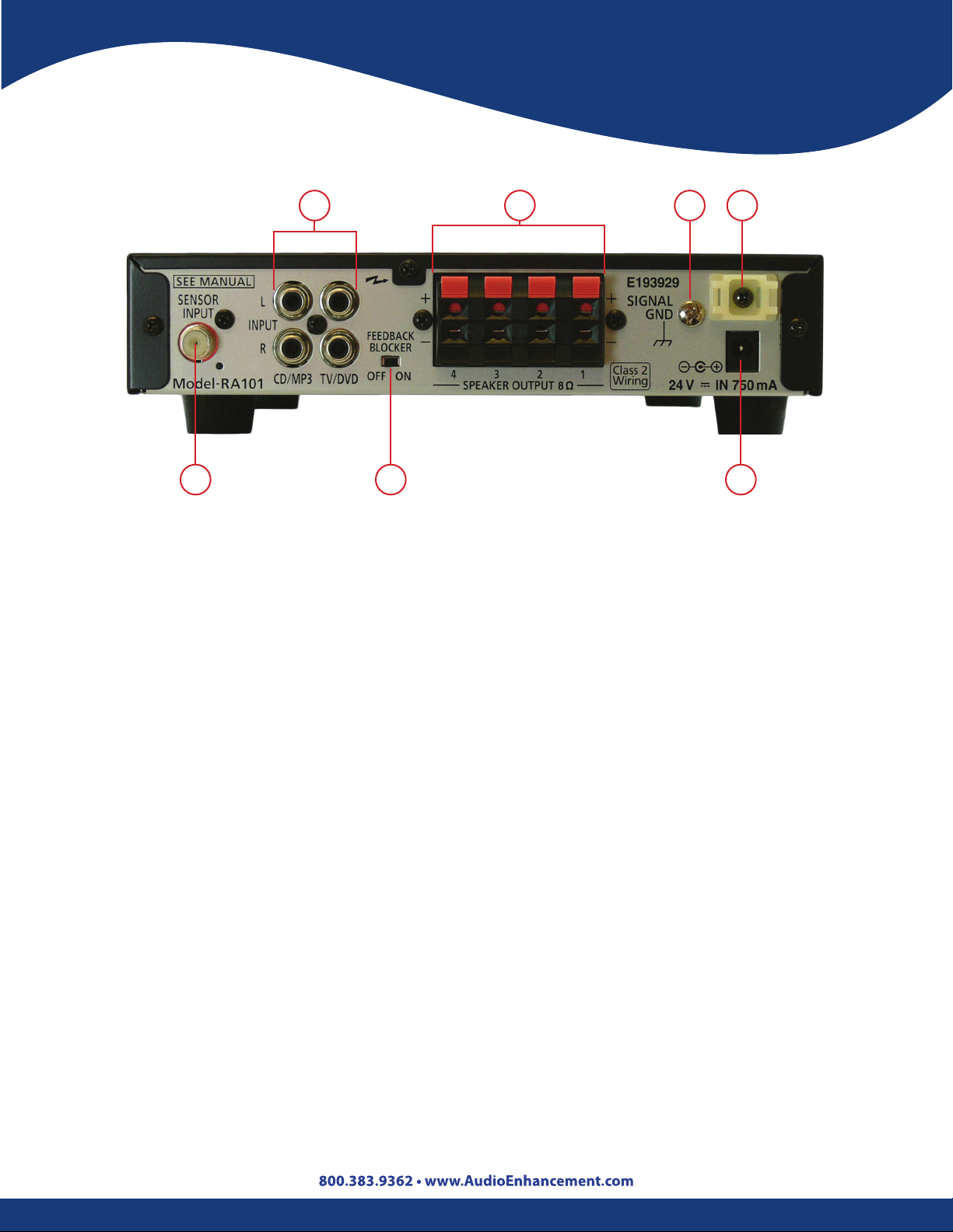
1. Feedback Blocker Switch [FEEDBACK BLOCKER OFF/ON]: Turn on this switch to enable
the feedback blocker. Default setting is OFF.
RA101
6543
2. Sensor Input Terminal [SENSOR INPUT 75 ]: Connect the infrared sensor via F-type
connector and coaxial cable. Also supplies power to the sensor (24 V).
3. Line Input Terminals [LINE INPUT 1, 2 -20 dBV 10k ]: Connect external audio devices
(such as a DVD player). Even if stereo playback device is connected, these terminals are
monaural.
4. Speaker Output Terminals [SPEAKER OUTPUT 1, 2, 3, 4, 8 ]: Connect speakers. Use
speakers with an impedance of 8 Ω.
5. Ground Screw [SIGNAL GND]: When the main unit is used with a combination of external
devices, connect the earth terminal of each device to reduce the dierences in potential
between devices.
6. Mount for Cable Clamp: Tie the cable with the cable tie.
7. DC Power Supply Terminal [24 V in, 750mA]: Connect the specied AC adapter for power.
Supplies 24 V DC power.
IDENTIFICATION
The vendor’s name, model number and the nature of supply are marked on the bottom of
the apparatus.
8
Operating Controls IR-2007
2
1
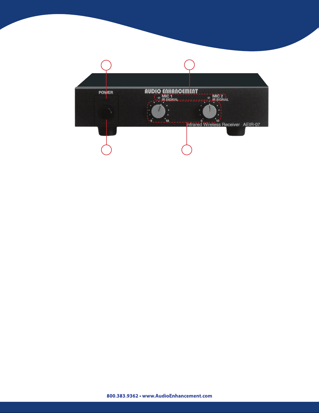
1. Power Switch: Turns the power ON/OFF.
2. Power Indicator: Lights green when the power is turned ON.
3. Infrared Microphone Volume Controls [Teacher 1 and 2]: Adjusts the volume level of
the infrared microphones.
4. Infrared Signal Indicators [MIC 1 IR SIGNAL, MIC 2 IR SIGNAL]: Lights green when the
infrared wireless receiver is receiving a signal.
4
3
AC Adapter: Use the “3A-621DA24” AC adapter provided to supply power to the IR-2007.
9
Operating Controls
IR-2007
1
3
2
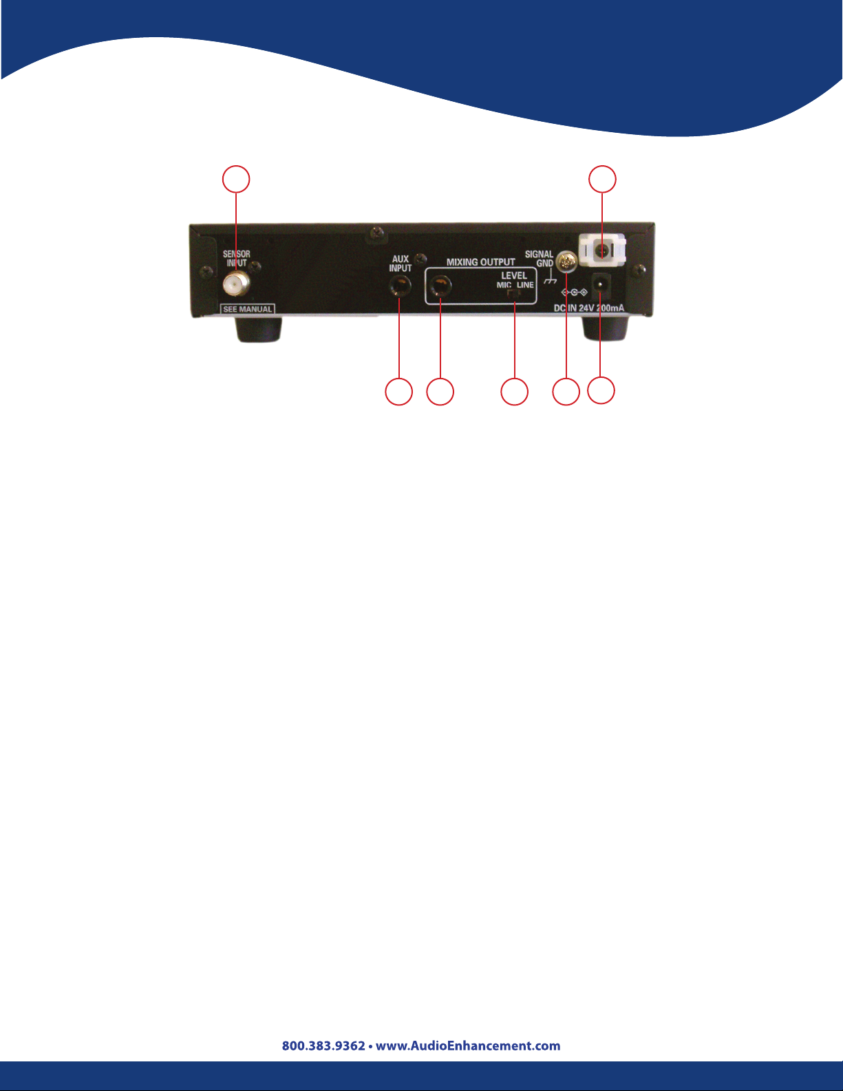
1. Sensor Input Terminal: Connection via F-connector and coaxial cable for the infrared
sensors. It also supplies power to the sensors (24 V).
2. Aux Input Terminal: Connections for TV/DVD, CD, COMPUTER, MP3, etc.
3. Mixing Output Terminal: Provides selectable line level or microphone level signal for input
into external amplier. Output provides mixed signal from both infrared microphone and
auxiliary input.
4
6
7
5
4. Output Level Selection: Allows selection of either line level or microphone level output.
5. Ground Screw [SIGNAL GND]: When the amplier is used with a combination of external
devices, connect the ground terminal of each device to reduce the dierence in potentials
between devices.
6. Mount for Cable Clamp: Used to bundle cables and speaker wires with tie wraps.
7. DC Power Terminal: The AC adapter provided supplies 24 V DC power.
IDENTIFICATION
The vendor’s name, model number and the nature of supply are marked on the bottom of the
apparatus.
10
Operating Controls
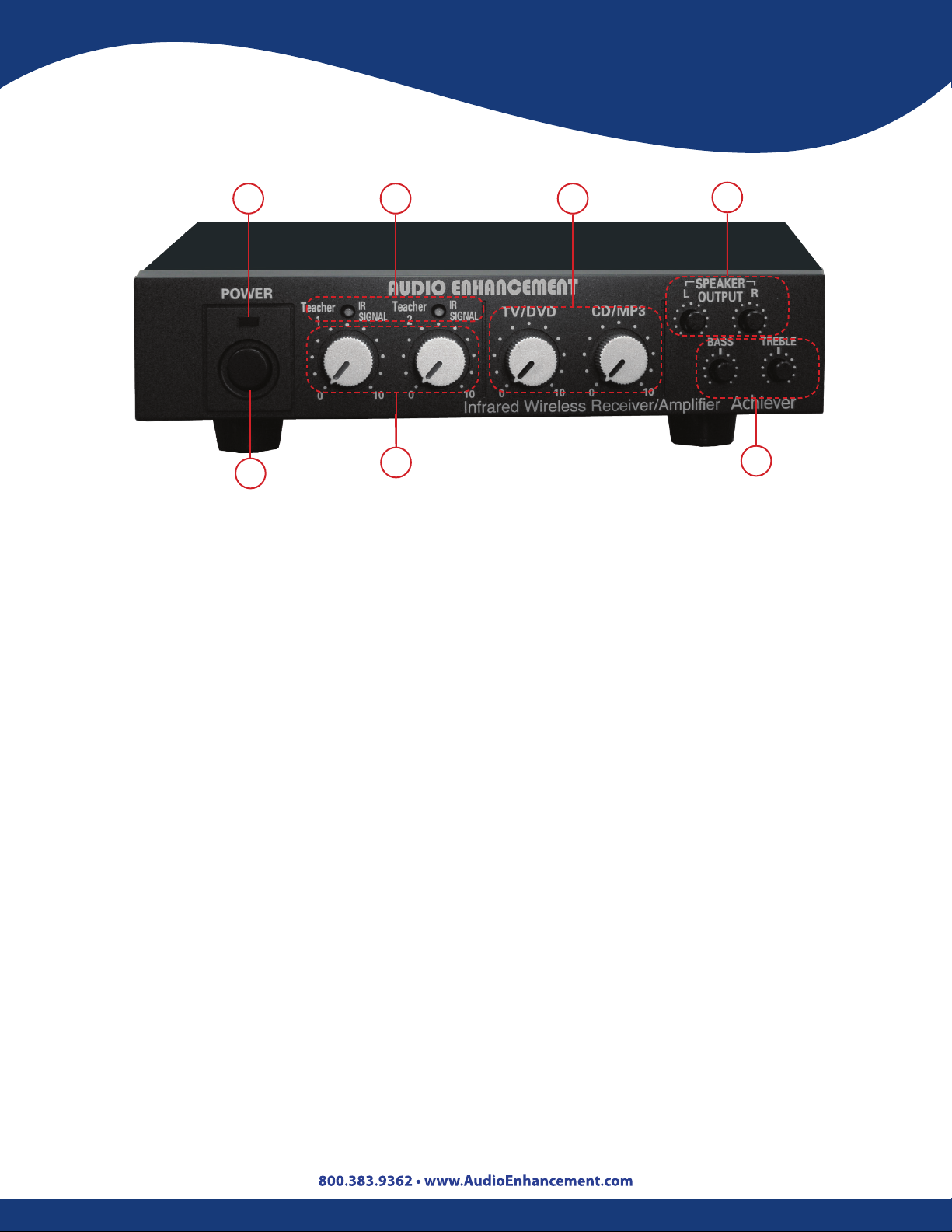
Achiever
2 4
1
1. Power Switch: Turns the power ON/OFF.
2. Power Indicator: Lights green when the power is turned ON.
3. Infrared Microphone Volume Controls [Teacher 1 and 2]: This control is used to adjust
the volume level of the infrared microphones.
3
5
7
6
4. Infrared Signal Indicators [Teacher 1 and 2]: Lights green when the infrared wireless
receiver is receiving a signal.
5. Auxiliary Input Volume Controls [TV/DVD and CD/MP3]: This control adjusts the volume
of the auxiliary inputs connected to the input terminals.
6. Equalizer Controls [BASS, TREBLE]: The BASS and TREBLE controls allow the teacher to
have control over the quality of his or her voice. This is achieved by adjusting the BASS lowrange or TREBLE high-range until the desired sound quality is achieved.
7. Speaker Output Volume Controls [SPEAKER L, R]: Output levels from each pair of speakers
are adjustable with this volume.
AC Adapter: Use the “3A-621DA24” AC adapter provided to supply power to the Achiever.
11

Operating Controls
Achiever
1
2
1. Sensor Input Terminal: Connection via F-connector and coaxial cable for the infrared
sensors. It also supplies power to the sensors (24 V).
2. Input Terminals [TV/DVD, CD/MP3]: Connections for TV/DVD and CD/MP3.
3
4
5 7
6
3. Line Output Terminal: Provides a line level output for connection of personal FM system,
recording devices, or video conferencing systems. All input signals, including microphones
and auxiliary inputs, are mixed and provided at the line output terminal.
4. Speaker Output Terminals: Connections for the speakers (8 ).
5. Ground Screw [SIGNAL GND]: When the amplier is used with a combination of external
devices, connect the ground terminal of each device to reduce the dierence in potentials
between devices.
6. Mount for Cable Clamp: Used to bundle cables and speaker wires with tie-wraps.
7. DC Power Terminal: Connect the specied AC adapter. Supplies 24 V DC.
IDENTIFICATION
The vendor’s name, model number and the nature of supply are marked on the bottom of the
apparatus.
12
Operating Controls
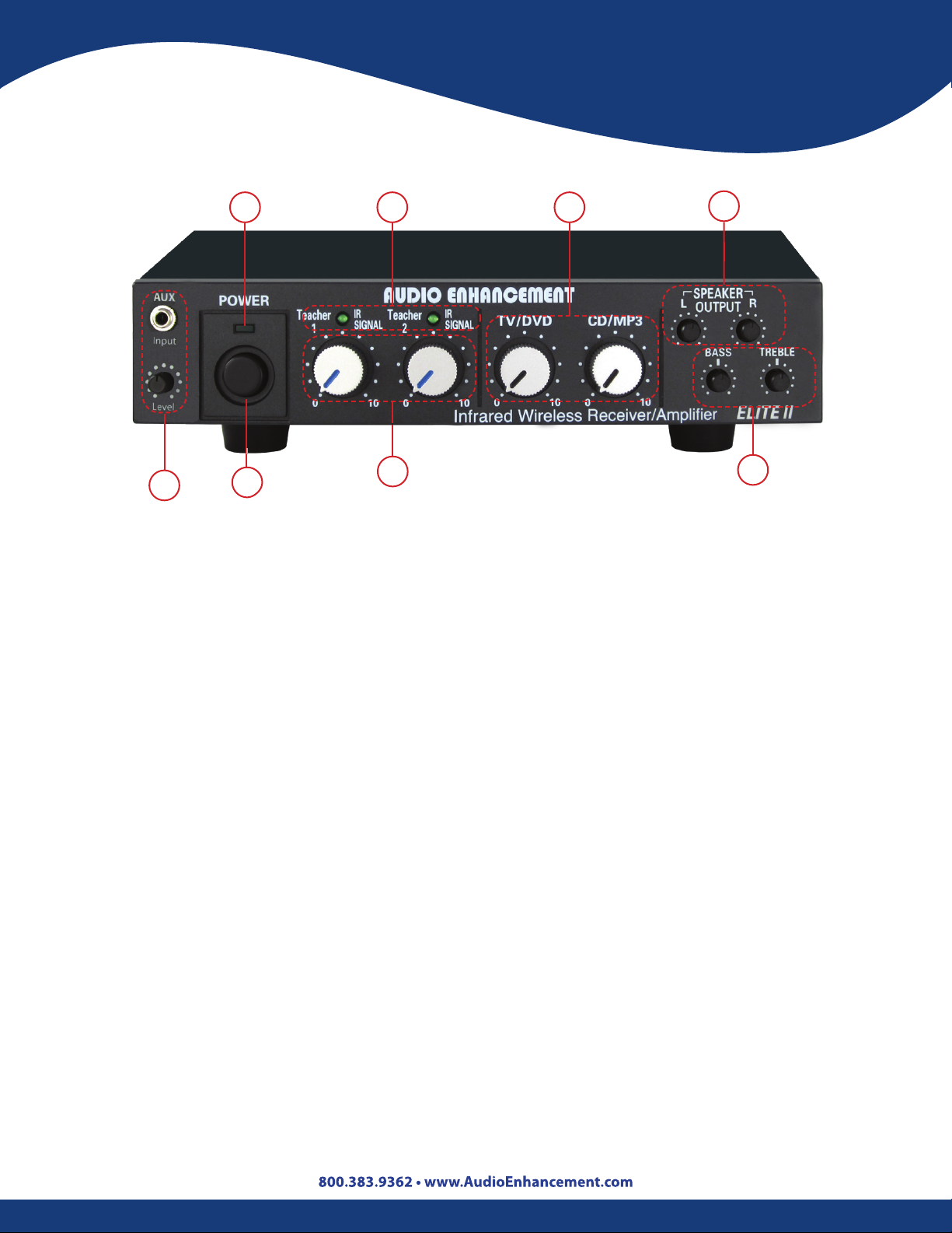
Elite II
2 4
8
1. Power Switch: Turns the power ON/OFF.
2. Power Indicator: Lights is green when the power is turned ON.
3. Infrared Microphone Volume Controls [Teacher 1 and 2]: These controls are used to
adjust the volume level of the infrared microphones.
1
3 6
5
7
4. Infrared Signal Indicators [Teacher 1 and 2]: Lights are green when the infrared wireless
receiver is receiving a signal.
5. Auxiliary Input Volume Controls [TV/DVD and CD/MP3]: These controls adjust the
volume of the auxiliary inputs connected to the input terminals.
6. Equalizer Controls [BASS, TREBLE]: The Bass and Treble knobs allow the teacher to have
control over the quality of his or her voice. This is achieved by adjusting the BASS low-range
or TREBLE high-range until the desired sound quality is achieved.
7. Speaker Output Volume Controls [SPEAKER L, R]: Output levels from each pair of
speakers are adjustable with the volume controls.
8. Front Auxiliary Input Volume Control: This control allows the teacher to adjust the level
of the input source connected to the input terminal on the front the amplier.
AC Adapter: Use the “3A-621DA24” AC adapter provided to supply power to the Elite II.
13
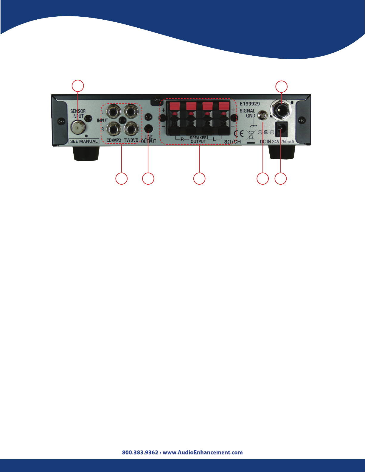
Operating Controls
Elite II
1
2
1. Sensor Input Terminal: Connection via F-connector and coaxial cable for the infrared
sensors. It also supplies power to the sensors (24 V).
2. Input Terminal [TV/DVD, CD/MP3]: Connections for TV/DVD and CD/MP3.
3. Line Output Terminal: Provides a line level output for connection of personal FM (Frequency
Modulator) system, recording devices, or video conferencing systems. All input signals,
including microphones and auxiliary inputs are mixed and provided at the line output
terminal.
3
4
5 7
6
4. Speaker Output Terminals: Connections for the speakers (8 ).
5. Ground Screw [SIGNAL GND]: When the amplier is used with a combination of external
devices, connect the ground terminal of each device to reduce the dierence in potentials
between devices.
6. PA Connector: Connects to Public Address (PA) system and mutes amplier during
announcements.
7. DC Power Terminal: Connect the specied AC adapter. Supplies 24 V DC.
IDENTIFICATION
The vendor’s name, model number and the nature of supply are marked on the bottom of the
amplier.
14
Operating Controls
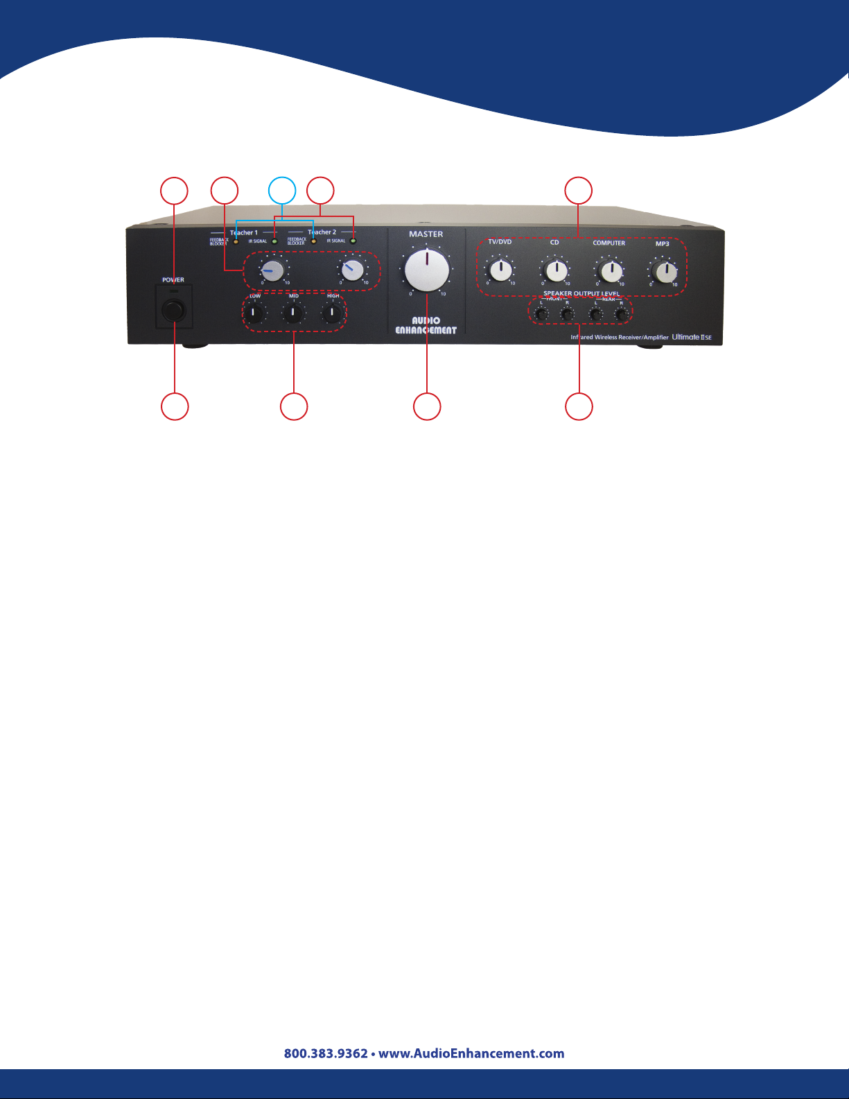
Ultimate IISE
2
1 78 9
1. Power Switch: Turns the power ON/OFF.
2. Power Indicator: Lights green when the power is turned ON.
3. Infrared Microphone Volume Controls [Teacher 1 and 2]: Adjust the level of the infrared
microphones.
4. Infrared Signal Indicators [Teacher 1 and 2]: Lights are green when the infrared wireless
receiver is receiving a signal.
3 5
4
6
5. Feedback Blocker Indicators (orange) [Teacher 1 and 2]: Lights turn orange when the
feedback blocker is activated.
6. Auxiliary Input Volume Controls [TV/DVD, CD, COMPUTER, and MP3]: Adjust the volume
of the auxiliary inputs connected to the input terminals.
7. Master Volume: Adjust all input volumes (3, 6) together.
8. Equalizer Controls [LOW, MID, HIGH]: The 3-Band Equalizer allows the teacher to have
control over the quality of his or her voice. This is achieved by adjusting LOW, MID, or HIGH
controls until the desired sound quality is achieved.
9. Speaker Output Volume Controls [FRONT L/R, REAR L/R]: The level from each speaker
can be independently adjusted with these controls.
AC Adapter: Use the PW-150A2-1Y-240E AC adapter provided to supply power to the Ultimate
IISE receiver/amplier.
15
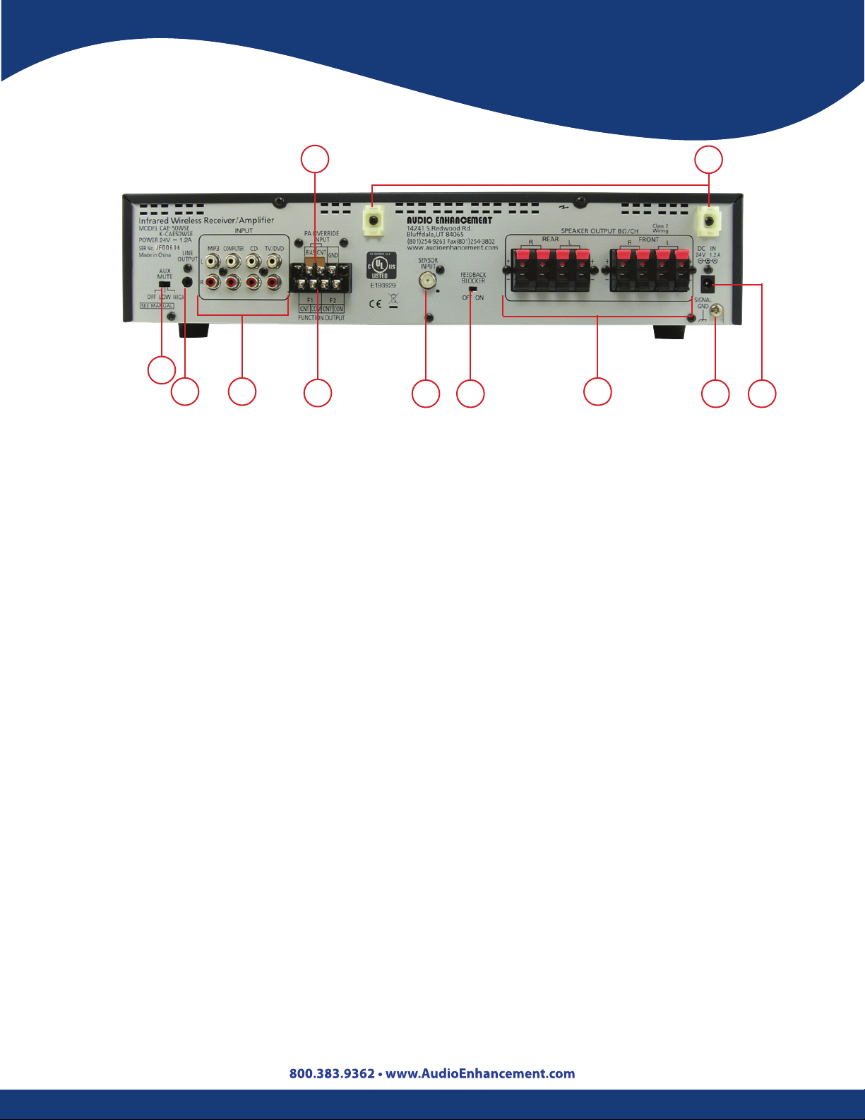
Operating Controls
Ultimate IISE
7
4
3 2 6 1
1. Sensor Input Terminal [SENSOR INPUT 75 Ω].
2. Input Terminals [TV/DVD, CD, COMPUTER, MP3]: Connections for TV/DVD, CD, COMPUTER, and
MP3.
3. Line Output Terminals [LINE OUTPUT 0 dBV 600 Ohm]: Connection for a recording or external
audio device. Output jack is 3.5 mm Tip/Sleeve (monaural).
5 8
10
9
11
4. Auto Mute Switch [AUTO MUTE OFF/LOW/HIGH]: Default setting is LOW. Sound from the
microphone will decrease the volume of external audio devices that are connected to the input
terminals. Detection sensitivity is controlled by the LOW and HIGH setting.
5. Feedback Blocker Switch [FEEDBACK BLOCKER OFF/ON]: Turn this switch ON to enable feedback
blocker. Default is OFF.
6. Function Terminals [PA OVERRIDE INPUT, BIAS/CNT/GND]: See Function Page #17.
7. Jumper Pin: Enable/Disable the PA override function. Default setting is Disable.
8. Speaker Output Terminals: Use speakers with impedance of 8 . Two speakers can be connected
to each of the four terminals.
9. Ground Screw [SIGNAL GND]: When the amplier is used with a combination of external devices,
connect the ground terminal of each device to reduce the dierence in potentials between devices.
10. Mount for Cable Clamp: Used to bundle cables and speaker wires with tie wraps.
11. DC Power Supply Terminal [24 V IN, 1.2 A]: Connect the specied AC adapter for power. Supplies
24 V DC.
16
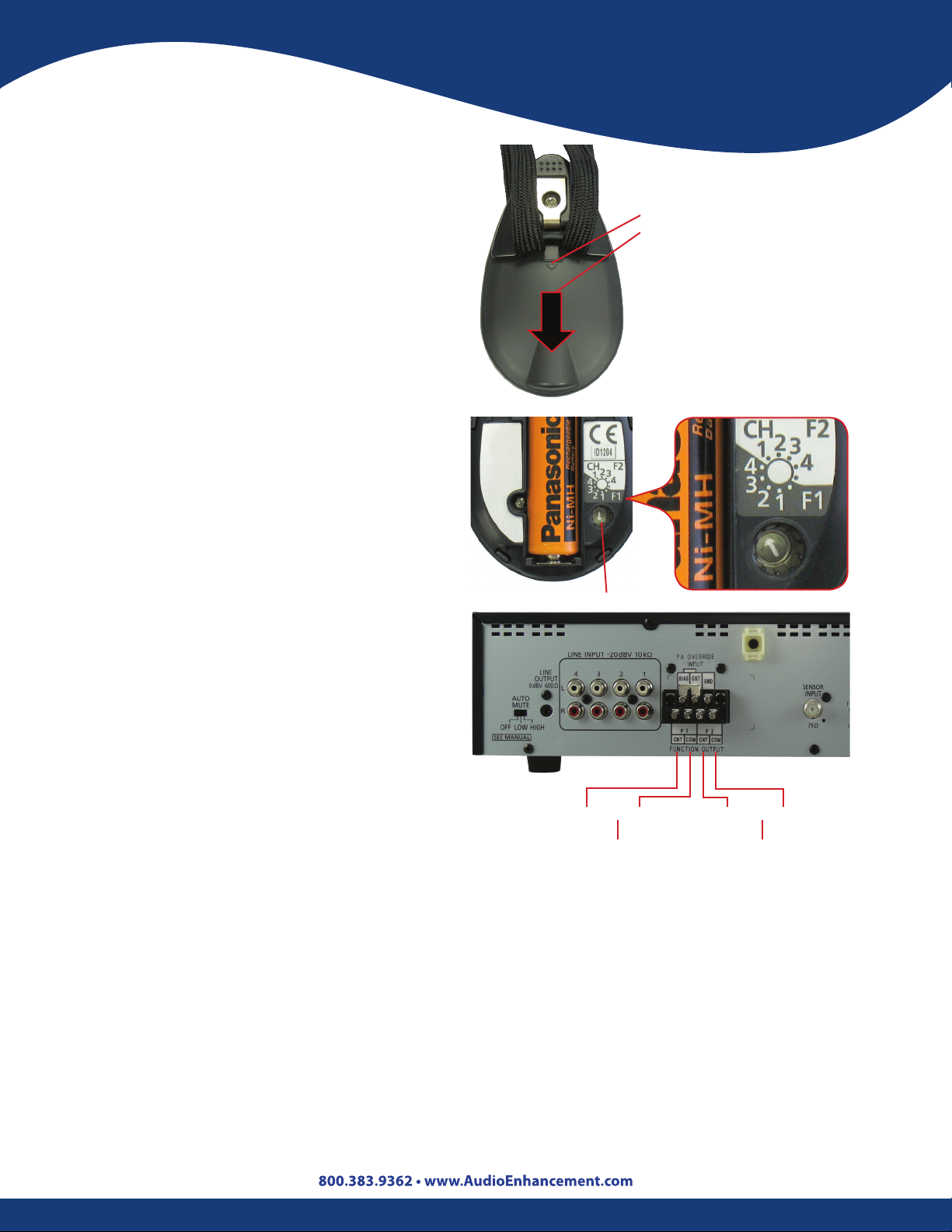
“F” Function
Setting the Function Channel on
the Teacher microphone
1. Remove the battery cover of the
microphone. Press down on the
battery cover with both thumbs and
pull down, in the direction of the arrow.
2. Set the transmitting channel and assign
function F1 or F2 with the channel
select control. To set the transmitting
channels and assign functions to the
function button, use the small channel
setting screwdriver (microphone’s
accessory) to turn the channel select
switch until it clicks into place.
3. Set the channel selector switch to the
desired channel. F2 is the Security Alert
function and F1 is the momentary
activation function. For normal use,
set the switch to CH1 in the F2 (white
background) area of the switch.
Back of Teardrop Microphone
Battery Cover
For Security Alert set to
CH1 in the F2 area
Channel Select Switch
Amplier Function Output
Connections
Function Outputs are opto-isolated and
are the equivalent of an Open Collector
NPN transistor that can handle a maximum
of 30 V DC at 20 mA. The CNT terminal is
the collector and the COM is the emitter.
Function Activation
F1 Function - The F1 Function activation provides for a momentary (300 ms) activation of the
F1 CNT and COM terminals every time the Function button is pressed. If the Function button is
pressed and held in F1 Function, it will provide a 300 ms activation every 600 ms. A 300 ms ON
followed by a 300 ms OFF, repeating until the Function button is released.
F2 Function - The F2 Function activation will cause the F2, CNT and COM terminals to activate
and remain activated until the receiver is powered OFF or the receiver does not receive an F2
signal from the microphone for three minutes.
The F2 transmission from a microphone can only be terminated by turning the microphone
power OFF.
F1-CNT F2-CNTCOM COM
Momentary Security Alert Constant
(To external devices)
17
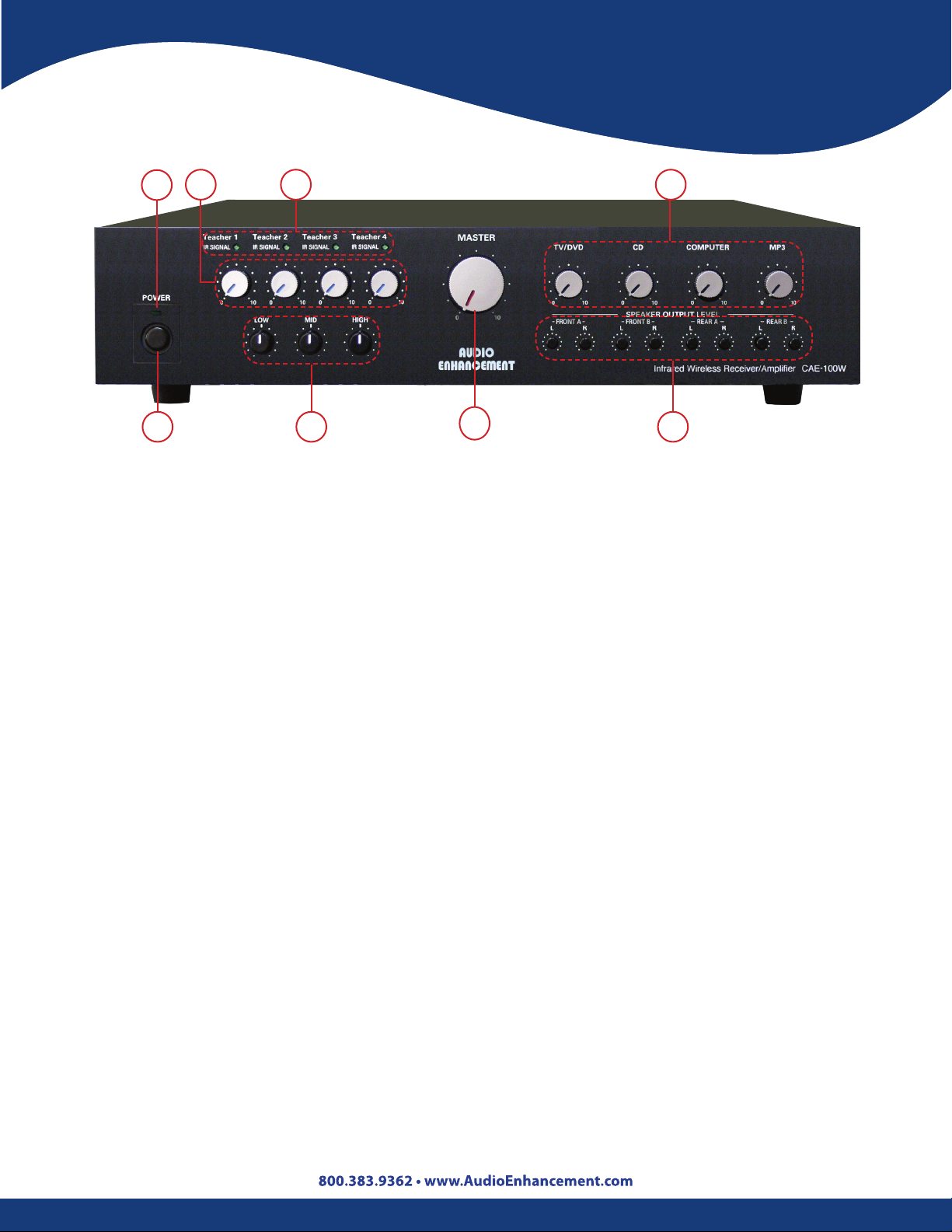
Operating Controls
Innovator
3
2
1 7 8
1. Power Switch: Turns the power ON/OFF.
2. Power Indicator: Light is green when the power is turned ON.
3. Infrared Microphone Volume Control [Teacher 1 to 4]: Adjust the volume levels of the
infrared microphones.
4. Infrared Signal Indicators [Teacher 1 to 4]: Lights are green when the infrared wireless
receiver is receiving a signal.
4
6
5
5. Auxiliary Input Volume Controls [TV/DVD, CD, COMPUTER, and MP3]: Adjust the volume
of the auxiliary inputs connected to the input terminals.
6. Master Volume: Adjusts overall level of the system.
7. Equalizer Controls [LOW, MID, HIGH]: The 3-Band Equalizer allows the teacher to have
control over the quality of his or her voice. This is achieved by adjusting LOW, MID, or HIGH
controls until the desired sound quality is achieved.
8. Speaker Output Volume [FRONT A L/R, FRONT B L/R, REAR A L/R, REAR B L/R]: The level
from each speaker can be independently adjusted with these controls.
AC Adapter: Use the “PW-150A2-1Y-240E” AC adapter provided to supply power to the Innovator
receiver/amplier.
18
 Loading...