

Page 1

Congratulations and thank you for your purchase of the Audio Note™ Kassai
mono power amplifiers. The Kassai is a Pure Class A Parallel Singled Ended valve
amplifier that uses the highly regarded 300B directly heated triode valve. The
Kassai produces a level of performance that is radically superior to current
designs and was specifically designed for sonic performance rather than technical
specifications. It also fulfills all Level 4 criteria.
- Pure Class A operation
- Zero negative feedback
- Single ended output stage
- Valve rectification
- Directly heated Triode
- Materials and component quality
This Level 4 amplifier has the following features: Audio Note™ silver wiring,
Audio Note™ copper foil signal capacitors, silver wound secondary on the output
transformer and 1 W Tantalum resistors.
UNPACKING AND INSTALLATION
These amplifiers are shipped without the valves installed. It is
necessary to install the valves first. It is
installed correctly or
warranty will result
serious damage that is not covered by the
. We recommend that your dealer does this for you.
essential
that the valves are
Installing the valves
Please take care when unpacking the amplifiers as they are fairly heavy and
place on a suitable clean space (table or floor) it is recommend that you store
the packaging materials in case the unit requires shipping at a later date.
Carefully unwrap all the valves. You will find 1x 6SN7WGTA, 2 x 300B and 1x
5U4G valves for each amplifier.
Looking from the front of the amplifier, the first valve to insert is the 6SN7WGTA
valve which goes into the first valve base at the front of the amplifier.
Inspect the locating pin on the bottom center of the valve and align with the
valve base (the locating pin can only go in one way round due to a locating
spigot) and with gentle but firm pressure insert the valve. Please see diagram 1.
MANUAL-ZX158
1
Page 2
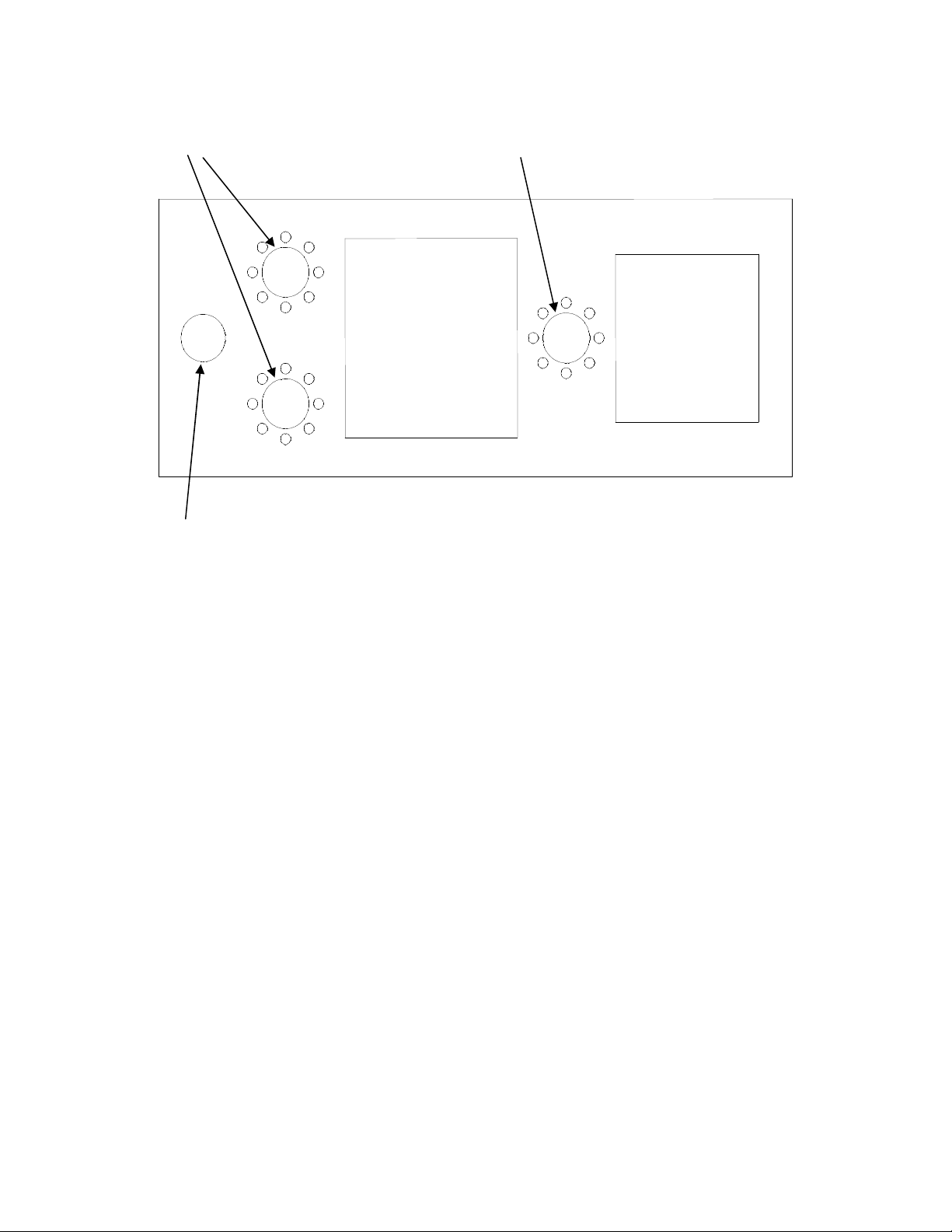
6SN7
300B 5U4G
Diagram 1: Kassai Tube Locations
Looking from the front of the amplifier, the next valve to plug in is the 5U4G
valve which goes into the last valve base at the back of the amplifier.
Inspect the locating pin on the bottom center of the valve and align with the
valve base (the locating pin can only go in one way round due to a locating
spigot) and with gentle but firm pressure insert the valve.
Looking from the front of the amplifier, the next valves to install are the 300B
valves which are inserted into the two 4 pin valve bases in the middle of the
amplifier.
It is absolutely vital that these valves are fitted correctly
(1) The larger pins must face the front of the amplifier when fitted to their valve
bases.
(2) The sticker on the valves base must also line up with the sticker on the
copper top plate, that is, A to A, B to B etc., or 1 to 1, 2 to 2 and so on.
Please make sure that both (1) and (2) are correct and with gentle but firm
pressure insert the valves into their sockets. Check again that all valves are fully
inserted in the correct way in their respective valve sockets. Follow the above
installation for both amplifiers.
MANUAL-ZX158
2
Page 3

Installation
Select a suitable location for the units ensuring that adequate ventilation
clearance is provided allowing at least 30cm. of space above the units. This is an
important consideration as the amplifier generates substantial heat during
normal operation. Be sure not to install the amplifier into a cabinet with
restricted air flow or onto a thick pile carpet.
In the interest of safe, reliable operation situate the amplifier away from
dampness or direct sunlight. Site the unit on a flat and firm surface capable of
sustaining the amplifier’s weight. Worthwhile sonic improvements may be
obtained by locating the amplifiers on a purposely designed audio support
system.
CONNECTION – Inputs
Each amplifier has a single RCA socket on the back panel for connection to your
preamplifier marked as Input. The sockets are colour coded Black for Left
channel and Red for Right channel.
CONNECTION – Speakers
Each amplifier is equipped with three colour coded standard binding posts for
connection to your speakers.
Connect the amplifiers black speaker output binding post marked as “ 0 ” to the
black terminal (also marked “ – “) on the speaker.
Connect the amplifiers red speaker output binding post marked “8 Ohm” to the
red terminal (also marked “ + “) on the speaker.
The other red speaker output binding post is marked “4 Ohm” and may be used
with 4 Ohm speakers. If you are uncertain whether your speaker system is of 4
MANUAL-ZX158
3
Page 4

or 8 Ohm type, try the following test once all other connections are made and
the amplifier is operational. Compare the sound quality using a familiar recording
with the speakers connected to the 8 ohm connections and then the 4 Ohm
connections respectively. The selection that produces the best frequency balance
and maximum dynamics should be used.
CONNECTION – Mains
Both amplifiers have an IEC mains inlet socket. Use the supplied mains cable to
connect the unit to the local mains supply. The mains fuse and a spare is located
in the inlet socket fuse drawer. The mains cable must be removed to access the
fuse or fuses.
Special Note – Make sure that all connection are tight and clean. For best results
use good quality audio interlinks. Although several companies make good quality
interlinks, those manufactured by Audio Note™ give the best performance with
Audio Note™ Amplifiers.
MANUAL-ZX158
4
Page 5

USING THE AMPLIFIERS
Once all the connections are completed and checked, turn on the amplifiers by
using the rocker switch located on the rear top right of the back panel just above
mains inlet socket. The amplifier requires approximately two minutes initializing
time before it is ready for operation. During this time ensure that the volume
control on your preamplifier is at the minimum setting.
A new amplifier requires about 200 hours of initial use (called “bedding in time”)
before the circuitry becomes stable and optimum performance is realized. As the
amplifier “beds in” the sound will become increasingly smoother, detailed and
open. Once the amplifier has “bed in” a warm up time of approximately 30 to 45
minutes is required each time the amplifiers are switched on before optimum
sonic performance is reached.
CAUTION – Valves can reach very high operating temperatures when in
use and can cause burns if touched.
MANUAL-ZX158
5
Page 6

AFTER CARE
No special maintenance is required for the amplifiers. A small feather or wool
duster is excellent for removing household dust from the valves and chassis.
Fingerprints and such may be cleaned with a soft cloth. Use a soft cloth
dampened in mild, warm and weak soapy solution to remove grease or oily
substances. Strong or alcohol based solvents may damage the finish on the
amplifiers. Dust or clean the amplifiers only when switched off and “cold”.
TUBE REPLACEMENTS
The valves used in the amplifiers should provide at least 6000 hours of
operation. These valves are specially selected and carefully matched by Audio
Note™ for use with the Kassai and should only be replaced with matched pairs.
Please consult your Audio Note™ dealer should the performance of the amplifiers
deteriorate so that arrangements for valve replacements can be made.
WARRANTY AND SERVICING
Audio Note™ warrants this product free from defects in materials and
workmanship for 1 year from original date of purchase from an appointed Audio
Note™ dealer. The valves are warranted for 3 months. In the event that your
Audio Note™ product requires servicing, please contact your Audio Note™
dealer. If the equipment needs to be shipped, please use the original packaging
and include a copy of the sales purchase receipt, with a note explaining in as
much detail as possible, the problems that you are experiencing with the unit.
Any modification not authorized by Audio Note™ will invalidate this
warranty.
If you require technical support, new valves or have any questions, please direct
them to your Audio Note™ dealer first or contact us directly.
Audio Note (UK) Limited,
25 Montefiore Road
Hove, East Sussex,
BN3 1RD,
United Kingdom
Tel: +44 (0)1273 220511
Fax: +44 (0)1273 731498
Email: info@audionote.co.uk
MANUAL-ZX158
6
Page 7

SPECIFICATIONS Per Mono Block
Weight 20 kg
Dimensions in mm 195(h) x 205(w) x 500(d) mm
Fuse Rating 2A anti-surge 110 to 120 VAC
1A2 anti-surge 220 to 240 VAC
Input Impedance 100kOhm
Maximum Output 18W RMS per channel
Into 4 or 8 Ohms
Input Sensitivity 250mV for full output
Channel Balance +/- 0.3db
Valve Compliment 1 x 6SN7WGTA, 1 x 5U4G, 2 x 300Bs
Power Consumption 135VA or 135 Watts
NB: Due to our desire to continually improve our products, specifications are
subject to change with out notice.
THIS PRODUCT COMPLIES WITH CE STANDARDS
MANUAL-ZX158
7
 Loading...