

Page 1
Dr. Device User’s Guide
Audio Damage, Inc.
Release 1.0
13 July 2007
Page 2

The information in this document is subject to change without notice and does not represent a commitment on
the part of Audio Damage, Inc. The software described by this document is subject to a License Agreement
and may not be copied to other media except as specifically allowed in the License Agreement. No part of this
publication may be copied, reproduced or otherwise transmitted or recorded, for any purpose, without prior
written permission by Audio Damage, Inc.
© 2007 Audio Damage, Inc. All rights reserved.
Credits
Software Design and Construction, Documentation
Chris Randall
Adam Schabtach
Field Testing
Wade Alin
Dean Dunakin
Steve Hamann
Dave Smith
Made Possible By
Tracie Bork
Lisa Randall
Fuzzy Logic
Alex
Chica
Fatty
Pablo
Widget
License Agreement
BY INSTALLING THE SOFTWARE, YOU ARE CONSENTING TO BE BOUND BY THIS AGREEMENT. IF YOU DO NOT
AGREE TO ALL OF THE TERMS OF THIS AGREEMENT, THEN RETURN THE PRODUCT TO THE PLACE OF
PURCHASE FOR A FULL REFUND.
Page 3

Single User License Grant: Audio Damage, Inc. ("Audio Damage") and its suppliers grant to Customer
("Customer") a nonexclusive and nontransferable license to use the Audio Damage software ("Software") in
object code form solely on a single central processing unit owned or leased by Customer.
Customer may make one (1) archival copy of the Software provided Customer affixes to such copy all
copyright, confidentiality, and proprietary notices that appear on the original.
EXCEPT AS EXPRESSLY AUTHORIZED ABOVE, CUSTOMER SHALL NOT: COPY, IN WHOLE OR IN PART,
SOFTWARE OR DOCUMENTATION; MODIFY THE SOFTWARE; REVERSE COMPILE OR REVERSE ASSEMBLE ALL
OR ANY PORTION OF THE SOFTWARE; OR RENT, LEASE, DISTRIBUTE, SELL, OR CREATE DERIVATIVE WORKS
OF THE SOFTWARE.
Customer agrees that aspects of the licensed materials, including the specific design and structure of
individual programs, constitute trade secrets and/or copyrighted material of Audio Damage. Customer agrees
not to disclose, provide, or otherwise make available such trade secrets or copyrighted material in any form to
any third party without the prior written consent of Audio Damage. Customer agrees to implement reasonable
security measures to protect such trade secrets and copyrighted material. Title to Software and
documentation shall remain solely with Audio Damage.
LIMITED WARRANTY. Audio Damage warrants that for a period of ninety (90) days from the date of shipment
from Audio Damage: (i) the media on which the Software is furnished will be free of defects in materials and
workmanship under normal use; and (ii) the Software substantially conforms to its published specifications.
Except for the foregoing, the Software is provided AS IS. This limited warranty extends only to Customer as
the original licensee. Customer's exclusive remedy and the entire liability of Audio Damage and its suppliers
under this limited warranty will be, at Audio Damage or its service center's option, repair, replacement, or
refund of the Software if reported (or, upon request, returned) to the party supplying the Software to
Customer. In no event does Audio Damage warrant that the Software is error free or that Customer will be
able to operate the Software without problems or interruptions.
This warranty does not apply if the software (a) has been altered, except by Audio Damage, (b) has not been
installed, operated, repaired, or maintained in accordance with instructions supplied by Audio Damage, (c) has
been subjected to abnormal physical or electrical stress, misuse, negligence, or accident, or (d) is used in
ultrahazardous activities.
DISCLAIMER. EXCEPT AS SPECIFIED IN THIS WARRANTY, ALL EXPRESS OR IMPLIED CONDITIONS,
REPRESENTATIONS, AND WARRANTIES INCLUDING, WITHOUT LIMITATION, ANY IMPLIED WARRANTY OF
MERCHANTABILITY, FITNESS FOR A PARTICULAR PURPOSE, NONINFRINGEMENT OR ARISING FROM A
Page 4

COURSE OF DEALING, USAGE, OR TRADE PRACTICE, ARE HEREBY EXCLUDED TO THE EXTENT ALLOWED BY
APPLICABLE LAW.
IN NO EVENT WILL AUDIO DAMAGE OR ITS SUPPLIERS BE LIABLE FOR ANY LOST REVENUE, PROFIT, OR
DATA, OR FOR SPECIAL, INDIRECT, CONSEQUENTIAL, INCIDENTAL, OR PUNITIVE DAMAGES HOWEVER
CAUSED AND REGARDLESS OF THE THEORY OF LIABILITY ARISING OUT OF THE USE OF OR INABILITY TO
USE THE SOFTWARE EVEN IF AUDIO DAMAGE OR ITS SUPPLIERS HAVE BEEN ADVISED OF THE POSSIBILITY
OF SUCH DAMAGES. In no event shall Audio Damage's or its suppliers' liability to Customer, whether in
contract, tort (including negligence), or otherwise, exceed the price paid by Customer. The foregoing
limitations shall apply even if the above-stated warranty fails of its essential purpose. SOME STATES DO NOT
ALLOW LIMITATION OR EXCLUSION OF LIABILITY FOR CONSEQUENTIAL OR INCIDENTAL DAMAGES.
The above warranty DOES NOT apply to any beta software, any software made available for testing or
demonstration purposes, any temporary software modules or any software for which Audio Damage does not
receive a license fee. All such software products are provided AS IS without any warranty whatsoever.
This License is effective until terminated. Customer may terminate this License at any time by destroying all
copies of Software including any documentation. This License will terminate immediately without notice from
Audio Damage if Customer fails to comply with any provision of this License. Upon termination, Customer
must destroy all copies of Software.
Software, including technical data, is subject to U.S. export control laws, including the U.S. Export
Administration Act and its associated regulations, and may be subject to export or import regulations in other
countries. Customer agrees to comply strictly with all such regulations and acknowledges that it has the
responsibility to obtain licenses to export, re-export, or import Software.
This License shall be governed by and construed in accordance with the laws of the State of Illinois, United
States of America, as if performed wholly within the state and without giving effect to the principles of conflict
of law. If any portion hereof is found to be void or unenforceable, the remaining provisions of this License
shall remain in full force and effect. This License constitutes the entire License between the parties with
respect to the use of the Software.
Page 5

Introduction
Thank you for purchasing Dr. Device, Audio Damage’s combination filter and delay plug-in. Dr. Device’s filter
features a warm, resonant four-pole low-pass filter with the overdrive and self-oscillation found in its analog
counterparts. The filter section provides several other filter modes as well as an analog-style soft-clipping
distortion stage and a very digital-sounding bitcrushing effect. Dr. Device’s delay provides a pair of Audio
Damage’s proprietary delay lines which recreate the unusual characteristics of older hardware delays. The
delays offer intuitive controls that produce complex rhythmic effects without the hassle usually associated with
setting up multi-tap delay effects.
Dr. Device also features an unusual modulation system for controlling the filter and delay effects. Instead of
the same old LFO, Dr. Device has a multi-dimensional, multi-node XYZ pad with a built-in motion recorder and
a novel kinetics system, giving the control nodes a life of their own. Dr. Device also offers full support for
VST/AU automation and MIDI controllers (VST version only).
System Requirements
To use Dr. Device, you'll need a Steinberg VST-compatible host application which conforms to the VST 2.0
specifications, and a computer capable of running it. For the AudioUnit version of Dr. Device, you’ll need an
application capable of hosting AudioUnit plug-ins, and a computer capable of running it. The following
specifications represent minimum requirements.
For use with Microsoft Windows: For use with Apple Macintosh:
Windows XP or Vista Mac OS X version 10.3.9 or newer
512 MB RAM 512 MB RAM
Pentium III 600 MHz CPU Motorola G4/G5 or Intel CPU
High Color S-VGA Display
Display capable of “thousands of colors”
Page 6

Installation
Double-click the Dr. Device Installer icon, and follow the instructions. During the installation process the
installer will ask you to enter your registration code. Your registration code uniquely identifies your purchase,
and you will need it if you need to reinstall your plug-in (for example, after upgrading to a new computer).
Keep a copy of the code in a safe location and please don’t share it with your friends. We’re delighted if you
like our products so much that you want to share them, but please ask your friends to buy their own copy so
that we can keep making new products.
To un-install from OS X, simply delete the plug-in from your VST folder, which is usually located at
/Library/Audio/Plug-Ins/VST/, and your AudioUnits folder, which is located at /Library/Audio/PlugIns/Components/. To un-install from Windows, use the included un-installer application.
Page 7

Operation
Dr. Device can be used in a mono, stereo, or mono-to-stereo context. In a stereo context, no summing of the
input channels happens; each channel passes through separate filters and delays. Dr. Device is useful as
either an insert effect or a send/return effect.
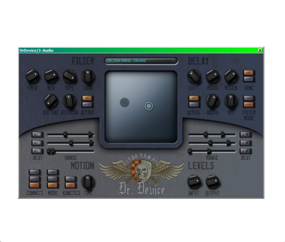
Here is a screenshot of Dr. Device, followed by detailed descriptions of its controls.
Page 8

1. Filter Controls
The FREQ controls the cutoff frequency of the filter. Rotate the knob clockwise to increase the cutoff
frequency.
The RES knob controls the resonance of the filter. As the resonance of a filter increases, the filter's output
emphasizes frequencies near its cutoff frequency. In plainer terms, if you turn up the resonance knob, the
filter sounds more “synthy”. (Try it—you'll hear what we mean.) If the filter type is set to 4PLP (see below)
and you turn the resonance knob fully clockwise, the filter will oscillate, producing a sustained tone even if the
plug-in has no input signal.
The TYPE knob switches the filter between several different filter models. As you rotate the knob, watch the
parameter display to see which filter type is active. The available types are:
Four-pole low pass (shown as “4PLP” in the parameter display) – the filter type most commonly found
in synthesizers. A low-pass filter attenuates or reduces signal frequencies greater than its cutoff
frequency and passes signal frequencies below its cutoff frequency without alteration. As you rotate
the frequency knob clockwise, the filter passes more of the signal's high-frequency content and the
output sounds brighter. If you turn the frequency knob fully counter-clockwise, you may not hear any
output at all because the entire signal has been filtered out.
Three-pole low pass (shown as “3PLP”): A low-pass filter with a frequency roll-off curve that is less
steep than that of the four-pole filter. Three-pole filters are fairly uncommon, but the three-pole lowpass filter found in a certain bass-line synthesizer sound defines entire genres of music.
Two-pole low pass (shown as “2PLP”): A low-pass filter with a frequency roll-off curve that is less
steep than either the three-pole or four-pole low-pass filter. Two-pole filters are usually used for
gentler frequency-shaping applications, such as in equalizers or tone controls, but are found on some
synthesizers.
Four-pole high pass (shown as “4PHP”): A high-pass filter works in a manner opposite to that of a low-
pass filter: it reduces signal frequencies less than its cutoff frequency and passes signal frequencies
above its cutoff frequency without alteration. As you rotate the frequency knob clockwise, the signal
loses its lower frequencies and the output sounds thinner. If you turn the frequency knob up far
enough, you might not hear anything at all because all of the signal has been filtered out.
Page 9

Two-pole high pass (shown as “2PHP”): If you've been paying attention you can probably figure this
one out for yourself, right? It's a high-pass filter that has a less steep attenuation curve than the fourpole high-pass filter. Use it when you want to create a thinner sound without the drastic low-frequency
reduction of the four-pole high-pass filter.
Four-pole band pass (shown as “4PBP”): A band-pass filter allows a range of frequencies centered on
the cutoff frequency to pass and attenuates higher and lower frequencies. The width of the band of
frequencies is controlled by the Resonance control. Wah-wah pedals used by guitarists are based on
band-pass filters.
The GAIN knob amplifies or attenuates the signal as it leaves the filter, changing its loudness. At its center 12
o'clock position it has unity gain, that is, it does not change the signal. Rotate the knob clockwise from this
position to make the signal louder, rotate it counter-clockwise to make the signal quieter.
The Soft Saturation (SOFTSAT) knob applies a variable amount of analog-like distortion to the signal before it
enters the filter. If the knob is rotated fully counter-clockwise it has no effect. As you rotate the knob
clockwise, the signal will become increasingly distorted.
The BITCRUSH knob applies a variable amount of digital distortion to the signal. If the knob is rotated fully
counter-clockwise it has no effect. The BITCRUSH effect works by resampling the signal with a lower sampling
rate, deliberately introducing digital artifacts and distortion. Rotate the knob clockwise to create an increasing
amount of digital destruction.
The ACTIVE buttons bypass or engage the filter, soft saturator, and bitcrusher. If the IN button is illuminated,
the filter and distortion effects are turned on. If the OUT button is illuminated, the filter and distortion effects
are bypassed altogether and have no effect on the signal passing through the plug-in. Click either button to
switch between IN and OUT.
2. Delay Controls
The knobs and buttons in the Delay section control Dr. Device's stereo delay effect. The delay receives its
input from the Filter section. If you're using Dr. Device in a mono context, the left and right channels of the
delay operate on the same input signal.
Page 10

The LEFT and RIGHT knobs control the amount of time that the signal is delayed in relation to the original
(post-filter) signal. The delay has a maximum time of two seconds. The exact delay times are displayed in the
parameter display at the top of the plug-in’s window.
The LEFT knob controls the delay time of the left channel. It operates in the manner you expect: turn it
clockwise to increase the delay time. The RIGHT knob is a little unusual. It controls the delay time of the right
channel, but operates as a multiplier of the time set by the LEFT knob. The RIGHT knob provides a selection
of simple multiplier values such as 1/2 which makes the right delay time one half of that of the left delay time.
The combination of the LEFT and RIGHT knobs enables you to create interesting rhythmic stereo delay
patterns without the complexity associated with setting up multi-tap delay effects.
If you turn on the SYNC switch Dr. Device uses the current tempo reported by your host to calculate its delay
time. When this switch is on, the time knob sets the delay length in metrical units, that is, fractions of a beat.
The range of values is 1/32nd to 1/1 (a whole measure), with dotted and triplet times available. Watch the
status display at the top of Dr. Device's window as you rotate the knob to choose a delay interval—or just do
it by ear. Triplet values are denoted with a “T” after the beat fraction, and dotted values are denoted with a
period. For example, “1/8 .” indicates a delay time with a dotted eighth note feel. Dr. Device will track tempo
changes, saving you from having to adjust its delay time by hand when you change the tempo of your song.
The REGEN knob, short for regeneration, feeds the delayed signal back into the delays. If the knob is set fully
counter-clockwise, none of the signal is fed back and you'll hear only a single delayed copy of the signal in
each channel. As you rotate the knob clockwise, more and more of the signal is fed back and you'll hear an
increasing number of repeats. If you rotate the knob fully clockwise the delayed signal will repeat indefinitely
and become increasingly loud with each repetition. Don’t say we didn’t warn you.
The WIDTH knob controls the stereo separation of the delayed signals. If the WIDTH knob is rotated fully
clockwise, the outputs of the delays are panned fully to the left and right. As you rotate the knob counterclockwise, the delayed signals move towards the center of the stereo field. If the knob is fully counterclockwise, the outputs of both delays are panned to the center.
The MIX knob varies the relative amounts of the original (dry) signal and the processed (wet) signal in the
plug-in’s output. The MIX knob is bidirectional. At its center position equal amounts of the wet and dry signal
are sent to the plug-in’s output. As you rotate the knob clockwise from the center position, the amount of wet
signal is increased and the amount of dry signal is decreased. Rotating the knob counter-clockwise from the
center has the opposite effect. If you rotate the knob fully clockwise or counter-clockwise, the plug-in’s output
will have only the wet or dry signal, respectively.
Page 11

The FILTER MODE switch chooses between two different tone-control options for the delays. In the BBD
position, the delays include a variable low-pass filter whose frequency depends upon the delay time. As the
delay time increases, the filter’s frequency decreases, recreating the limited-bandwidth characteristics of
analog delays that used “bucket-brigade” delay circuits. In the DIGI position, the low-pass filter has a fixed,
fairly high frequency, providing a gentle amount of high-frequency roll-off which helps the delayed signal mix
well with the original.
The ACTIVE switch connects and disconnects the delays from the signal path. If the ACTIVE button is set to
OUT the inputs to the delays are muted. Click either button to switch between IN and OUT.
3. The XYZ Pad
The square region in the center of Dr. Device's window is a two-dimensional control called the XYZ pad. The
XYZ pad has two circular handles that can be moved horizontally and vertically when you click and drag them
with the mouse. For brevity, and lack of a better term, we refer to the circular handles as nubbies. Borrowing
from geometry, the letters X and Y refer to the directions, or axes, that you can move the nubbies. X ref ers to
the horizontal direction or axis, Y refers to the vertical direction/axis. The nubbies also have a third axis called
Z, whose value is determined by whether or not the mouse button is clicked when the pointer is over the
nubby1. Usually you'll use your mouse or other main input device to move the nubbies, but you can also move
them with MIDI Continuous Controller messages.
The DEST buttons (short for Destination) and sliders next to the lower-left and -right corners of the pad let
you use the nubbies to control Dr. Device's parameters. The controls on the left are for the light -colored
nubby; those on the right are for the dark nubby. (Notice the small images of the nubbies on the Dest
buttons.) Each nubby can control up to three parameters at once. You can control only one parameter with
each nubby axis, and, conversely, any parameter can be controlled by only one axis.
The range sliders determine the range of values over which movements of the XYZ nubbies change their
destination parameters. Each range slider has two moveable handles. The left handle sets the lowest value
that the destination parameter will reach when controlled by the XYZ pad. The right handle sets the highest
value that the parameter will reach.
1 Yes, since there are actually three axes of motion, technically we could call Dr. Device's pad a three-dimensional
controller. That sounds a little presumptuous, though, doesn't it?
Page 12

For example, suppose that the X axis of a nubby is assigned to control the filter frequency, the left handle of
the X-axis range slider is positioned about ¼ of the way from the left end of the slider, and the right handle is
positioned about ¾ of the way from the left end, like this:
Now, when you move the nubby all the way from the left edge of the XYZ pad to the right edge, the filter
frequency knob will rotate through about half of its range, from about the 10 o'clock position to about the 2
o'clock position. If the Y axis of the nubby was assigned to the filter resonance, and the range slider handles
were positioned as shown above, the resonance knob would rotate from its center 12 o'clock position up to its
maximum value as you moved the slider vertically from the bottom to the top of the XYZ pad.
4. Motion Controls
The controls in this section determine the various ways the nubbies can move about, and their relationship
with each other. Using the motion controls with the nubbies, you can create fairly sophisticated modulation
sources which can then be used to drive the effect in rhythmic ways.
The CONNECT buttons hook the two nubbies together. If the nubbies are connected, they move as a unit.
Both nubbies still control any parameters assigned to their axes of motion, so you can control up to six
parameters at once by moving just one of the nubbies. The CONNECT button has three different settings
which affect how the nubbies are connected:
With the FREE setting, the nubbies are not connected and operate completely independently.
Page 13

With the LOCK setting, the nubbies are connected
together. Moving either nubby moves the other by the
same amount, and clicking either nubby also causes
the other nubby's Z-axis value to also change from
zero to one. A solid line appears between the nubbies
when the LOCK mode is engaged.
With the LINK setting, the nubbies are connected
together but the dark-colored nubby can be moved
independently of the light-colored nubby. Moving the
light nubby moves the dark one by the same amount,
but moving the dark nubby does not move the light
one. Clicking the dark nubby does not cause the light
nubby's Z-axis value to change. The LINK mode lets
you change the relative position of the nubbies
without disconnecting them. A dotted line appears
between the nubbies when the LINK mode is
engaged.
Page 14

The MODE buttons control Dr. Device's motion recorder. The motion recorder is a built -in automation
mechanism that records and plays back the movements of the nubbies. Dr. Device makes separate recordings
for each nubby, so you can first record a series of movements for one nubby and then record another series of
movements for the other nubby while the first one moves by itself. You can also have the motion recorder
control the movements of one nubby while you move the other with your mouse.
When the OFF button is illuminated the motion recorder is inactive and doesn't affect the nubbies.
When the REC button is illuminated the motion recorder is ready to record the movement of the nubbies.
When you click on a nubby the recorder will start recording as you move the nubby around. The recording
ends when you release the mouse button, and the motion recorder starts playing back the recorded motion.
The time it takes for the recorded motion to be played back is controlled by the TIME knob; see below.
When the PLAY button is illuminated the motion recorder plays the movements recorded for one or both
nubbies. The movements are played back in a looped fashion; as soon as the movement reaches the end of
the recording it starts over again at the beginning. The recordings for both nubbies always take the same
amount of time to play back, as determined by the TIME knob described below.
The TIME knob determines the amount of time it takes for the motion recorder to play back the recorded
motion of the nubbies. This time is always synchronized to the current tempo of your host sequencer. The
playback duration is displayed in the parameter display at the top of the window, and is expressed as a
fraction of a measure. For example, if the display shows 1 / 2 the nubbies will move through their recorded
motions twice in each measure. Rotate the TIME knob clockwise to increase the amount of time it takes to
play back the motion recordings, counter-clockwise to decrease the amount of time. The TIME settings range
from 1 / 32 of a measure to 2 measures. Note that the playback duration of the motion recorder is entirely
independent of how long you moved the nubby around while making the recording.
Note: Dr. Device’s motion recorder depends upon accurate synchronization information from your host. Not
all hosts provide this information (even though it is required by the VST 2.0 specification). If your host does
not provide sync info, Dr. Device’s motion recorder will not work.
Motion recordings are stored with Dr. Device's presets. Each preset has one recording for one or both nubbies.
To erase the motion recording for a nubby, hold down the CTRL key if you’re using Windows, or the CMD key
if you’re using OS X, while clicking on the nubby. To erase the recordings for both nubbies, hold down the
CTRL or CMD key while clicking the MODE switch.
Page 15

If the KINETICS button is turned on, the nubbies move by themselves after you move them with the mouse. If
you release the mouse button as you drag a nubby, it will continue to move with the same speed and direction
that you dragged it. In other words, you can push the nubbies with the mouse and they'll coast in the
direction that you push them. (Think of an Air Hockey table.) The nubbies bounce off the sides of the pad area
and will continue to move until you turn the KINETICS button off. If the nubbies are connected in either the
Link or Lock mode, they'll bounce around the pad together, staying a fixed distance apart. Try it—it makes
more sense to see it than to read a description of it.
The kinetics system operates as part of Dr. Device’s signal processing. Some hosts turn off plug-ins when
audio is not passing through the plug-in to conserve CPU cycles. If your host turns off Dr. Device, the nubbies
will cease to move.
If you hold down the CTRL key (for Windows) or the CMD key (for OS X) while clicking the KINETICS button,
the velocities of both nubbies will be set to zero and their motion will cease. This can be handy if you give one
of the nubbies a good shove and it bounces around so quickly that you can’t catch it with the mouse pointer.
The motion recorder has priority over the kinetics. If you've already recorded the motion of one or more
nubbies and set the MODE of the motion recorder to PLAY, the KINETICS button will have no effect on the
nubby or nubbies controlled by the motion recorder. However, you can use the motion recorder to control just
one of the nubbies, leaving the other to bounce around freely when KINETICS is turned on.
5. Level Controls
The Level knobs let you boost or reduce the level of the signals entering and leaving the plug-in. Both have an
operating range of -40dB (nearly silencing the signal) when rotated fully counter-clockwise to +3dB
(amplifying the signal by a small amount) when rotated clockwise. In most circumstances you'll probably not
need to adjust these controls. The Input knob can be used to reduce the input signal's level if you find that it
seems to be overloading the filter, and the Output knob can be used to adjust Dr. Device's overall output
loudness.
Page 16

MIDI Controllers
The VST version of Dr. Device responds to MIDI continuous controller messages. You can use hardware MIDI
controllers, such as MIDI slider boxes or the knobs found on some MIDI keyboards, to adjust Dr. Device’s
parameters.
The VST version of Dr. Device has a simple “MIDI Learn” mode for assigning its controls to MIDI controllers.
To assign a control to a MIDI controller:
First, hold down the shift and ctrl keys on your PC’s keyboard, or shift and cmd keys if you’re using a Mac, and
click once on the control. A white box will be drawn around the control to indicate that it is ready to learn
which MIDI controller it will be assigned to.
Next, move the MIDI controller to send a continuous controller message—turn the knob, press the button,
move the slider, whatever is appropriate.
The white square will disappear. Now the control will move when you manipulate the MIDI controller.
Dr. Device waits until it has received two consecutive continuous controller messages with the same controller
number before it makes an assignment. This filters out extraneous data sent by some MIDI controllers. If you
are assigning a button or switch on a MIDI controller, you may have to press or move the switch twice before
Reverence recognizes the controller and assigns it to the desired control.
To assign a different MIDI controller to a control, repeat the same procedure using a different controller.
To cancel MIDI Learn mode without assigning a controller, hold down the SHIFT and CTRL keys (SHIFT and
CMD keys on a Mac) and click in any empty area in Dr. Device’s window (i.e., don’t click on another control).
The white box will disappear.
To remove a MIDI controller assignment from a control, SHIFT and CTRL keys, (SHIFT and CMD keys on a
Mac) click on the control once so that the white box appears, then click again on the same control.
Dr. Device’s MIDI controller assignments apply to all presets and instances of Dr. Device, in all host
applications that you use. The MIDI assignments are stored in a special file on your hard drive. The contents
of this file are read when Dr. Device is loaded by your host. If you have two or more instances of Dr. Device in
Page 17

use at once, any MIDI assignments you make will not be propagated to the other instances until the next time
that your host loads the plug-ins.
Dr. Device automatically makes three MIDI assignments when instantiated. The X, Y, and Z axes of the lightcolored nubby are assigned to MIDI control numbers 12, 13, and 92 respectively. You may find these
assignments are useful if you happen to own a popular performance-oriented touchpad device and effects
unit.
The AudioUnit version does not provide the same MIDI assignment features as the VST version. Almost all
AudioUnit hosts provide their own mechanism for assigning MIDI controllers to parameters, so it would be
redundant for us to implement MIDI controller assignments in the plug-in itself. Consult the documentation for
your AudioUnit host to learn how to use its MIDI features.
Automation
Almost all of Dr. Device's parameters can be automated using your host's automation features. Consult your
host's documentation for information on how to use these features.
Dr. Device only transmits parameter-change messages for automation for controls that you move yourself.
When you move a nubby or turn a knob with the mouse, automation data for the nubby or knob is transmitted
to your host. Automation data is not transmitted when the nubbies move in response to either the Kinetics
feature or the motion recorder. Nor is any automation data transmitted for parameters controlled by the
nubbies. If you connect a nubby's axis to a parameter and move the nubby with the mouse, automation data
for only the nubby will be received by the host; no data will be received for the targeted parameter.
And Finally…
Thanks again for purchasing Dr. Device. We make every effort to ensure your satisfaction with our products,
and want you to be happy with your purchase. Please write support@audiodamage.com if you have any
questions or comments.
 Loading...