

Page 1

CONTENTS
SCENARIO 1
INTRODUCTION 3
UNPACKING 3
VISUAL INSPECTION 3
SPECIFIC POINTS 3
IMPORTANT SAFETY INSTRUCTIONS 5
POWER SUPPLY UNIT 6
TECHNICAL SPECIFICATION 8
EQUALISATION CURVES 12
CONNECTOR PANEL 13
CONNECTIONS 14
MODULE LAYOUT AND FUNCTIONS
MICROPHONE/LINE INPUT MODULE 16
STEREO LINE MODULE 20
OUTPUT MODULE 22
ADJUSTMENTS AND CALIBRATION 24
MASTER MODULE 26
MONITOR MODULE 29
M-S NOTES 34
COMMUNICATIONS MODULE 37
CUSTOMER NOTES AND FACTORY MODIFICATIONS 44
TECHNICAL LIBRARY 45
Page 2

SCENARIO
Time was when it became necessary to update the ubiquitous AD145 PICO mixer.
Our survey showed two main requirements: as well as Audio Developments' build and
audio qualities, narrower and shorter modules were required, and the simple but
effective equaliser from PICO had to be retained. By this time, 4-track recording
equipment had begun to trickle into the marketplace (Nagra D etc), so we decided to
give the new mixer four outputs. Because of the lower noise-floor of modern digital
recorders, the level of input signals may be reduced. We have taken advantage of this
fact and lowered the slope ratio of the limiters to 7:1. By so doing, not only is signal
distortion greatly reduced, but also the artefacts associated with limiters become
much less noticeable or objectionable. Also, sixty years after the event, sound
engineers have come to realise the potential of Blumlein's M-S techniques; to this
end, facilities have been incorporated to take advantage of these techniques. The
result is AD146 - a four-output mixer.
This was followed by AD148 - edit mixer. Based on AD146, two comprehensive left
and right monitor modules have been added for editing purposes. If a mic/line module
is included for commentary or voice-over purposes, its input-gain switch can be
changed to a potentiometer, and its gain structure changed to ensure consistent level
matching with a fixed, mechanical point of reference. Unfortunately, this way of
working does reduce headroom and also compromises a mixer's noise performance.
After AD146/AD148 it was back to the drawing board. Our customers were still
demanding a two-output mixer - as a true replacement for the PICO, and with the
PICO's simplicity. Despite past assurances to the contrary, T powering is still
required. And could we incorporate auxiliaries? And could we possibly bring it to
market at 'entry level'? We have, and we have and that's MERCURY (AD147).
AD149 completes the 140 series of mixers, and has a repertoire of party tricks not to
be found in any other mixer - not even for 'ready money'. The design team
took, as its starting point, our list of all the ideas and suggestions presented to us over
the past few years. Many of these requests came from film-sound recordists - a subset of recordists we have unintentionally neglected in the past.
Since the days of R & D for AD146, channel insert points suddenly became
de rigueur. It transpires that many sound engineers have experienced the power of
FLEX-EQ, our industrial-strength equaliser, and wish to be able to use it when making
original recordings.
Being latter-day converts, we have included circuitry to take full advantage of all
M-S techniques - even shuffling - in both production and post-production.
Comment [AH1]: Page: 1
1
Page 3

AD149 is Audio Developments' tribute to, and celebration of the genius of Alan Blumlein.
We appeal to all AD149 users to break with tradition and, just on this occasion, study
the manual to reveal all the mixer's secrets. THIS IS ESSENTIAL
Well - we HAD every intention that AD149 would complete the 140 series. We'd
reckoned, however, without the persistence - nay, insistence - of our customers for a
mains-operated version of the AD146 with four auxiliaries ... we've called it AD144.
2
Page 4

INTRODUCTION
Unpacking
If there are any signs of damage to the outside of the carton, please notify us or your
supplier immediately, regardless of the unit's apparent physical condition. This is in
case a claim has to be made at a later date because of previously undetected transit
damage. The packaging material should not be discarded until the mixer has been
acceptance tested and a suitable transit/storage case is available for secure, safe
storage.
Visual Inspection
Identification - please make a separate note of the serial number for your own capital
equipment records. Ensure that it agrees with the number on the invoice/packing
note. The serial number label is on the case exterior.
Configuration - check that the correct number and combination of input modules have
been installed. If, for any reason, you wish to change the positions of the modules, do
not do so until after completion of any acceptance tests. Any tests then made will be
to a known configuration and can be compared with our factory records.
Temperature - check the meter glasses for condensation. If the package has been in
transit during cold weather, leave the mixer for at least 12 hours to allow it to return to
normal room temperature. Any measurements or subjective tests then made, will be
to a known temperature reference.
Specific Points
Until the mixer has been acceptance tested we strongly recommend that modules are
not removed for adjustment. If adjustments are necessary, refer to the section on
adjustments and calibration. All customer functions are external, except the following.
Limiter threshold - is set at the factory at +8dBu (PPM 6), but an internal preset
potentiometer allows adjustment to any other level above 0dBu. The limiters are to be
found on the left-hand PCB of the output module. Presets are also available for
adjusting limiter attack and release times.
Line-up tone - at 1kHz and 10kHz is calibrated on the meters to PPM4, giving a line
output level of 0dBu with A, B, C, D faders set to maximum. NOTE - PPM4
refers to the mark on a BBC PPM Scale. Other meter scales have a different mark at
0dBu level. Alternative calibration levels are possible via the internal preset.
RH-output ident - as an alternative to continuous tone on all main outputs; B & D
outputs can be pulsed with tone for 3 seconds.
3
Page 5

Module fix screws - Hexagon head screws are used to fix the modules and back
cover. The size being 1.5mm HEX A/F with a 2.5M thread.
If it becomes necessary to remove modules or back cover it is strongly advised using
a good quality hexagonal head driver.
Use of a screwdriver, however desperate, is not recommended.
Microphone powering - the mixer will remain unconditionally stable if the powering on
unterminated input channels is switched off - this also improves the noise
performance and crosstalk. Powering - phantom (or 12v tonader) - may be selected
before or after the microphone is connected to the module.
Surfaces - every working surface is covered by a hard plastic membrane which is
printed on the reverse side. These surfaces may be cleaned by most solvents, and
without fear of the legends being erased.
Connectors - for convenience, the connector panel is labelled for reading from above.
All connectors are in line with their corresponding module.
Every input module is mechanically shielded against radio-frequency interference.
In order to facilitate the testing and calibration of all modules, a set of two extender
modules is available from the factory.
ABBREVIATIONS
PPM peak programme meter
VU volume unit
VR variable resistor
X-Y coincident stereo-microphone
A-B spaced-apart stereo-microphone
M-S middle-side; techniques and microphone described by A D Blumlein
PCB printed circuit board
HPF high-pass filter
Finally, may we draw your attention to our range of portable, battery-operated
audio-toys called PORT-A-FLEX (AD066) which will complement your new mixer.
No 1 - broadcast quality compressor/limiter. Nos 3, 7, 8, 10 - distribution amplifiers
for microphone- and line-level signals. No 13 - the aforementioned FLEX-EQ in its
portable guise.
We wish you many trouble-free hours of use from your mixer. As a company, we are
fully committed to BS EN ISO 9001. Should you have any problems or require any
further information on FLEX-EQ or the M-S microphone technique, please do not
hesitate to contact us on 01922 457007 or by fax on 01922 457008 or by e-mail
sales@audio.co.uk.
4
Page 6

WARNING
IMPORTANT SAFETY INSTRUCTIONS
The user of electrical products must be familiar with their potential dangers, and
fundamental precautions must always be taken. Please read the following text
carefully.
Power supply units manufactured or supplied by Audio Developments Ltd are not user
serviceable. There are no user-serviceable parts associated with any such power
supply unit.
THE OUTER COVERS MUST NOT BE REMOVED
Such a power supply unit is solely for use with audio mixers and sound processors -
hereafter called the equipment - manufactured by Audio Developments Ltd.
Always use a cord set accepted by a National Approved Body.
EARTHING/GROUNDING: When using an external power supply unit that is
connected to the mains supply to drive the mixer it must be CONNECTED TO
EARTH.
In certain types of malfunction or breakdown, earthing provides a path of least
resistance for electric current and considerably reduces the risk of electric shock.
DANGER: Incorrect connection of the equipment grounding/earthing conductor can
result in the risk of electric shock. Where possible obtain a pre-wired mains lead from
a reputable supplier with the correctly fitted mains connector for the type of mains
outlet in use; otherwise, one correctly wired and checked by a qualified electrical
engineer. If your mains lead is not suitable for the mains outlet, have the correct plug
fitted by qualified personnel.
The MAINS PLUG of this equipment is the primary disconnect device. Therefore, in
the final application, ensure it remains close to the equipment and easily accessible.
5
Page 7

MAINS POWER SUPPLY
Also refer to IMPORTANT SAFETY INSTRUCTIONS
XP plc Model No AEH45UM21
The mains POWER SUPPLY UNIT is suitable for driving an Audio Developments
AD144 Mixer. This power supply unit has two voltage rails: +12V DC and -12V DC,
capable of supplying a minimum of 1A per rail, power the audio electronics. (The
+48V DC rail, capable of supplying 300mA, is generated internally using a DC-DC
Converter and powers the phantom supply for condenser microphones).
NOTE: The AEH45UM21 power supply unit is designed to power mixers without an
internal battery facility - and therefore no DC-DC Converter exists to generate
the+12V & -12V supplies. If such facilities are available, a power supply unit which is
a single-rail device, must be used.
The AEH45UM21 may be powered from either a 110/120V AC source or a 220/240V
AC source. The power supply unit automatically recognises the different source
voltages. Operating the equipment at the wrong voltage could be hazardous.
For connecting the power supply unit to the mains, always use a suitable nationally
approved cord set. If such a set is unavailable, care must be taken to connect the
LIVE, NEUTRAL and EARTH pins of the power supply’s IEC mains connector to
the corresponding terminals associated with the AC source. This work must be
undertaken by a qualified engineer.
FOR SAFETY REASONS, AEH45UM21 POWER SUPPLY UNIT MUST BE
CONNECTED TO MAINS EARTH. Any maintenance to the power supply unit or its
mains cable assembly must be performed by a suitably qualified engineer.
FUSES: It is recommended that the mains power cord is fused.
250mA HRC TYPE T 240V AC
For continued safety the specified fuse link must be fitted in the mains fuse holder
when a replacement is required. Ensure it is of a type approved by a National
Approved Body.
Each DC supply rail is protected by its own fuse - fitted internally: refer to the
TECHNICAL LIBRARY. Only suitably qualified personnel must service the power
supply unit. If any fuse link fails it is strongly recommended the cause is traced.
Only genuine spare parts with identical specifications must be used.
It is DANGEROUS to change the specification or modify the product in any way.
6
Page 8

DC OUTPUT XLR CONNECTIONS
Pin 1 0V
Pin 2 +12V DC
Pin 3 -12V DC
Pin 4 NO CONNECTION
Pin 5 0V
NOTE: The power supply unit contains no user serviceable parts inside. Refer
servicing to qualified service personnel.
DO NOT REMOVE THE OUTER COVERS
7
Page 9

TECHNICAL SPECIFICATION - ELECTRICAL
REFERENCE 0dB = 775mV at 1kHz unless otherwise stated
MAX GAIN MIC 85 75 65 55 45 35 dB
LINE 50 40 30 20 10 0 dB
MAX INPUT LEVEL MIC -42 -32 -22 -12 -2 +8 dB
LINE -7 +3 +13 +23 +33 +43 dB
RETURNS +24 dB
INPUT MIC >1k5Ω
IMPEDANCE LINE >10kΩ
RETURNS >100kΩ
MIC POWERING +48V DC and +12V DC PHANTOM POWER
+12V TONADER (to order)
MAX OUTPUT +23.5dBm (600R LOAD) - A,B,C,D; MASTER, AUX 1,2,3,4:
TRANSFORMER BALANCED
CLEAN FEED/CHANNEL OUT; ELECTRONIC BALANCED
+18dBm (600R LOAD) - MON 1 L&R; MON 2 L&R; AUX 1,2,3,4:
TRANSFORMER BALANCED
MON 2: UNBALANCED STEREO JACK
OUTPUT <60R A,B,C,D; AUX1,2,3,4; MON 1; MON2; CLEAN FEED/CH
IMPEDANCE <20R MON 2 (HEADPHONES JACK)
FREQUENCY +0; -1.5dB 20Hz to 20kHz MAIN/AUXILIARY SIGNAL PATHS
RESPONSE +0; -1.8dB 20Hz to 20kHz MONITOR SIGNAL PATHS
EQUALISATION LF; SHELVING ±10dB @ 100Hz VARIABLE TURNOVER
MAX ±15dB @ 30 Hz
MF; PEAK/DIP ±15dB @ 2k8Hz Q = 1.2 RECIPROCAL
HF; SHELVING ±10dB @ 10kHz VARIABLE SLOPE
MAX ±15dB @ 30kHz
HIGH-PASS -3dB @ 90Hz and 150Hz, 12dB/OCTAVE SLOPE
FILTER
HARMONIC <0.03% @ 1kHz 0dBm OUTPUT
DISTORTION <0.15% @ 40Hz to 20kHz +15dBm OUTPUT
CROSSTALK >70dB 40Hz to 15kHZ INTERCHANNEL & INTERGROUP
>55dB 40Hz to 15kHz BETWEEN L&R ON STEREO CHANNEL
8
Page 10

NOISE MIC <126dB 20Hz to 20kHz 200R SOURCE
(WITH RESPECT TO THE INPUT)
LINE <70dB SIGNAL-TO-NOISE RATIO 20Hz to 20kHz
LIMITER THRESHOLD +8dB
RATIO 7 : 1
ATTACK 2ms (SET AT FACTORY)
(VARIABLE VIA INTERNAL PRESET)
RELEASE 250ms (SET AT FACTORY)
(VARIABLE VIA INTERNAL PRESET)
POWERING EXTERNAL POWER SUPPLY UNIT
±12V DC, 5-PIN XLR
7W (WITHOUT MICROPHONE POWERING)
9
Page 11

TECHNICAL SPECIFICATION - MECHANICAL
AD144 is supplied with 12, 14, 16 or 18 input modules. A separate meter bridge fitted
with 4 VU or PPM meters is supplied to read outputs A,B,C and D. The mixer's meters
can then be dedicated to auxiliary 1 & 2, auxiliary 3 & 4 and monitor 1/PFL outputs.
SIZE
WEIGHT
12 I/P 14
16 I/P 18 I/P
I/P
A 598 659 720 781
B 562 623 684 745
DIMENSIONS IN MILLIMETRES
12 I/P 14 I/P 16 I/P 18 I/P
16.0 18.5 21.0 23.5
WEIGHTS IN KILOGRAMS
10
Page 12

SIZE
A
DROP THROUGH VERSION OF MOUNTING
12 I/P 14 I/P 16 I/P 18 I/P
B 568 630 690 751
C 613 674 735 796
MEASUREMENTS IN MILLIMETRES
WEIGHT AS PREVIOUS
562 623 684 745
11
Page 13

EQUALISATION CURVES
12
Page 14
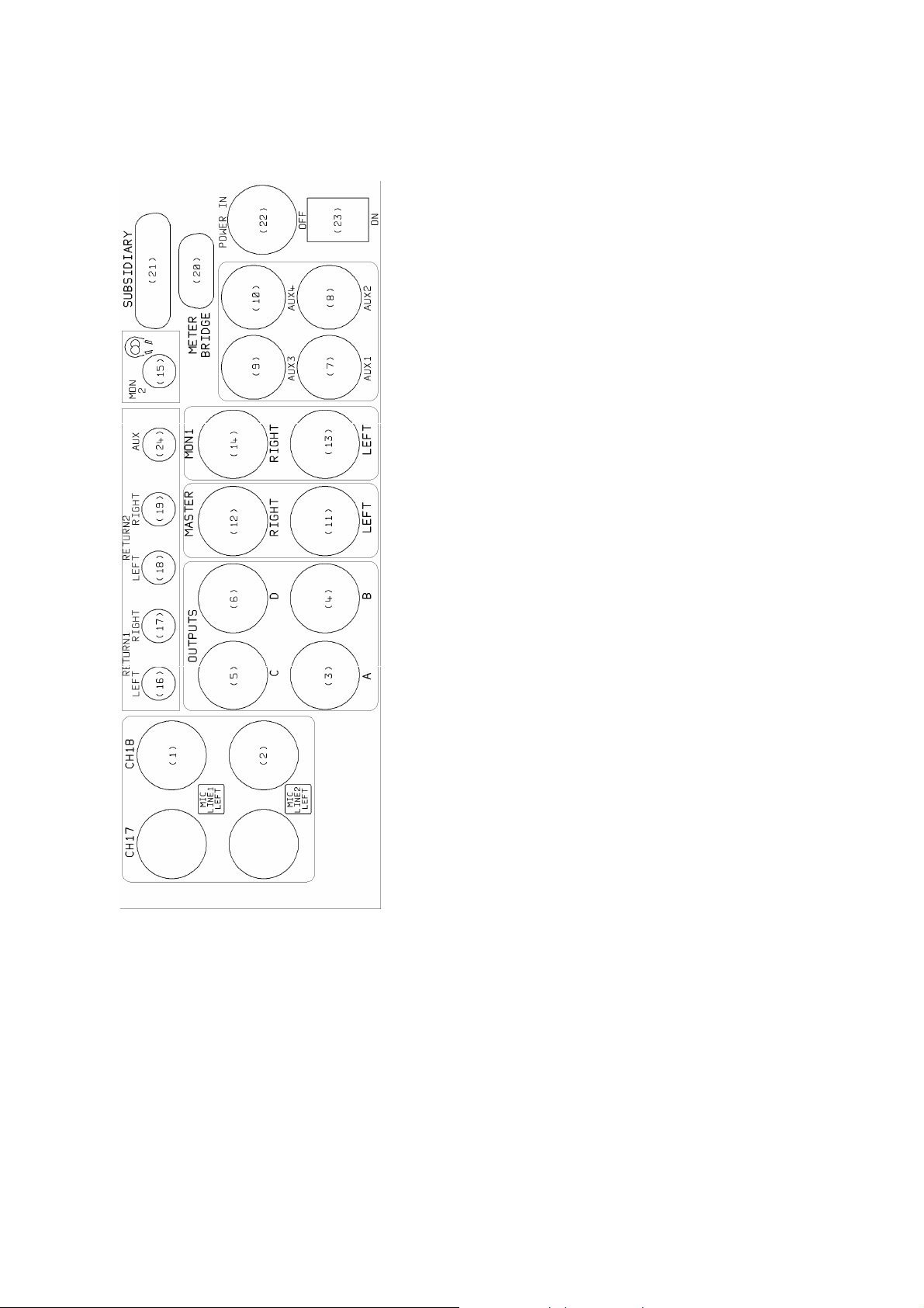
CONNECTOR PANEL
Mic/Line Module
(1) Microphone input
(2) Line-Level input
Stereo Line Module
(1) Line input left
(2) Line input right
Outputs
(3) Main A output
(4) Main B output XLR
(5) Main C output XLR
(6) Main D output XLR
(7) Auxiliary 1 output XLR
(8) Auxiliary 2 output XLR
(9) Auxiliary 3 output XLR
(10) Auxiliary 4 output XLR
(11) Master
Left output XLR
(12) Master Right output XLR
Monitor outputs / inputs
(13) Monitor 1 Left output XLR
(14) Monitor 1 Right output XLR
(15) Monitor 2 output jack socket
(16) Return 1 Left jack socket
(17) Return 1 Right Jack socket
(18) Return 2 Left jack socket
(19) Return 2 right jack socket
(24) Auxiliary Return jack socket
Meter bridge connector
(20) Remote start / Subsidiary
connector
(21) External DC power input
(23) Off/On switch
All input and output impedances and levels are to be found in the TECHNICAL
SPECIFICATION.
13
Page 15

All inputs to, and outputs from AD144 are to be found on the connector panel.
Balanced inputs and outputs are on XLRs.
XLR Pin 1 Shield
Pin 2 Signal +
Pin 3 Signal -
In the case of an unbalanced line-input, pins 1 & 3 should be connected.
Main (3) to (6), auxiliary (7) to (10) and master (11) & (12) outputs are
transformer-balanced, and are at line-level.
When driving unbalanced loads, the mixer outputs may be safely unbalanced by
connecting pins 1 & 3. This will not lead to a loss of output level.
The electronically-balanced stereo-returns enter the mixer on two pairs of standard,
'A' type stereo jacks (16/17) and (18/19). The Auxiliary Return (L & R) enter the mixer
on a ‘A’ type stereo unbalanced jack (24)
Monitor 1 output is transformer-balanced and appears on two XLRs (13) and (14), left
and right.
Monitor 2 output is on an ‘A’ type stereo jack (15) for driving headphones (with a
capability of +15dBm into 600 ohms) or other monitor loads. This is duplicated
(unbalanced) on an 'A' type stereo jack on the monitor module.
BALANCED JACK STEREO UNBALANCED JACK
Tip Signal + Tip Left Signal
Ring Signal - Ring Right Signal
Sleeve Shield Sleeve Shield
A two-position rocker switch (23) allows power to enter the mixer, which is confirmed
by the MIX ON LED (9) on the output module.
External powering of the mixer is via a 5-pin XLR (22).
XLR Pin 1 0V
Pin 2 +12V
Pin 3 -12V
Pin 4 NC
Pin 5 0V
14
Page 16

‘D’ connectors for METER BRIDGE and REMOTE START are as follows:
CONN (20) METER BRIDGE
IDC D PIN CONN. STD D PIN IDC D PIN CONN. STD D PIN
1 Chassis 1 8 Output D 12
2 0V 9 9 NC 5
3 0V 2 10 Output C 13
4 Output master left 10 11 NC 6
5 +V Lamp 3 12 Output B 14
6 Output master right 11 13 -V rail 7
7 Spare 4 14 Output A 15
15 +V rail 8
CONN (21) SUBSIDIARY
STD D PIN CONNECTION STD D PIN CONNECTION
1 Chassis 13 Comms return-Signal 2 Relay switch - Common 14 0V
3 Relay 5 - Switched 15 - V Power out
4 Relay 4 - Switched 16 +V Power out
5 Relay 3 - Switched 17 NC
6 Relay 2 - Switched 18 Spare
7 Relay 1 - Switched 19 Spare
8 Comms output 2 20 Spare
9 Comms output 3 21 Spare
10 Comms output 1-Left 22 Spare
11 Comms output 1- Right 23 Spare
12 Comms return-Signal + 24 Spare
25 Relay 5 control
15
Page 17

MICROPHONE/LINE MODULE
amplitude
control
control
A,B,C,D outputs
and indicator LED
(1) Phantom power toggle
(2) Phase- change toggle
(3) Input-gain selector
(4) High-frequency
(5) Mid-frequency amplitude
(6) Low-frequency amplitude
(7) Auxiliary 1 level
(8) Auxiliary 2 level
(9) Auxiliary 3 level
(10) Auxiliary 4 level control
(11) Panoramic
(12) Individual routeing to
(13) Pre-fade listen
(14) Overload LED
(16) Line-input toggle
(17) High-pass filter
(18) EQ selector
(19) Aux 1 source selector
(20) Aux 2 source selector
(21) Aux 3 source selector
(22) Aux 4 source selector
(23) Matrix selector
(24) Routeing to monitor
(15) Channel fader
16
Page 18

The discreet and discrete microphone amplifier is the one designed for AD146 and
has been tried, tested and proved in the field and in the studio. The transformerbalanced, ultra-low-noise amplifier does not require an input attenuator as the
available 50dB gain change is achieved with a 6-position rotary switch (3) acting on
the feedback alone - in 10dB steps. This has the advantage of not degrading signalto-noise performance as the gain is reduced. (On request, the rotary switch may be
replaced with a potentiometer for continuously-variable control.)
A DC voltage is available for phantom powering, either at 48v or 12v, condenser
microphones (1). If the T (tonader) powering option has been included in the mixer, it
will be selected by switch (1) to 12v.
The line input is isolated from the microphone power and no damage can be done to
external equipment if microphone power remains selected when the channel is
switched to accept a line input (16). Such is the isolation between signal paths, a
microphone input (Conn 1) and a line input (Conn 2) may simultaneously be
connected to a channel.
With line selected (16), input gain switch (3) at 35 and channel fader (15) at 0dB, the
mixer has unity gain, with 10dB gain in reserve. (All output faders must be set at 0dB.)
Phase change (2) follows the mic/line selector and is therefore active on both inputs.
φ1 is the normal position.
The high-pass filter (17) is also active on both inputs and precedes the input
transformer. In this position, the filter protects the transformer against saturation and
overload caused by excessive low-frequency content in the input signal. The highpass filter has a slope of 12dB/octave and is -3dB at 150Hz in position 2 and -3dB at
90Hz in position 3. The filter is independent of the equaliser.
The EQ selector switch (18) routes the signal through the equaliser section. The
high-frequency control (4) has an amplitude of ±10dB at 10kHz, with variable slope.
The mid-frequency control (5) has an amplitude of ±15dB at 2.8kHz, with a
proportional-Q of 1.2. The low-frequency control (6) has an amplitude of ±10dB at
100Hz, with variable turnover. The EQ switch (18) auditions the signal pre and post
equalisation without disturbing chosen settings.
There are four auxiliary sends from the module; each has its own source selector
combined with an on/off switch, and each has its own level control which acts purely
as an attenuator. The auxiliary sends are independent of the channel mute (routeing
switches) and, therefore, it is essential that the AUXILIARY OFF position is
immediately and positively identifiable. To this end, the order of functions on source
selectors (19) to (22) has been very carefully chosen. When the level controls (7) to
(10) are set at 0 and sources selected to post fader, auxiliary outputs will have the
same level as the module output(s), and will track with them.
The overload LED (14) illuminates 3dB before clipping at the input to the channel
fader (equaliser output).
17
Page 19

S-switch (23) creates a matrix amplifier across an adjacent pair of input modules.
Refer to M-S NOTES.
The panoramic potentiometer (11) routes the signal proportionately
between A and/or C outputs (L) and B and/or D outputs (R). Routeing switches (12)
are independent of each other and also act as channel mutes.
The monitor 1 path is the true output from the module (independent of any other
routeing) and is derived from the output of the panpot - and S-switch (23) if selected.
MON (24) routes the channel signal to the L&R monitor 1 modules and is auditioned
when CH (1) is selected on BOTH monitor modules. This monitor 1 output also
automatically appears on monitor 2 (headphones) output. MON can also be used as
an AFL (after-fader listen) function, ie to monitor the mono output of the module. In
this case, select MON (24), and CH (1) on EITHER monitor module.
Non-destructive SIP (solo-in-place) usage of MON is outlined in the MONITOR
MODULES section.
If the post-fader channel output (clean feed) option has been included, the signal will
appear on a stereo jack in the centre of (XLR) CONN 2. Alternatively, it may be
chosen to replace LINE input on Conn 2. Situated on the module’s main PCB
is (DIL) SW 16 to select the signal pre or post fader. (DIL) SW 17 allows the
module to drive unbalanced loads - without a reduction in signal level. Refer to
TECHNICAL LIBRARY.
PFL (13) routes the signal at the fader input to monitor 2, ie the headphones-output
jack and balanced L&R outputs on XLRs. PFL overrides any other signal appearing
on monitor 2.
The Penny & Giles fader (15) is calibrated 10dB down from its fully open position,
allowing the operator to work with 10dB of gain in reserve. Faders on adjacent
modules can be coupled for stereo operation by the use of standard ganging clips.
18
Page 20

This page is blank
19
Page 21

STEREO LINE MODULE
control
amplitude
control
routeing switch
and indicator LED
(1) Input-changeover toggle
(2) Phase-change toggle
(3) Input-balance control
(4) High-frequency amplitude
(5) Mid-frequency
(6) Low-frequency amplitude
(7) Auxiliary 1 level
(8) Auxiliary 2 level
(9) Auxiliary 3 level
(10) Auxiliary 4 level
(11) Width
(12) L, R, A/B, C/D
(13) Pre-fade listen
(14) Overload LED - left & right
(16) EQ selector
(17) Aux 1 source selector
(18) Aux 2 source selector
(19) Aux 3 source selector
(20) Aux 4 source selector
(21) Matrix selector
(22) Routeing to monitor
(15) Channel fader
20
Page 22

For optimum performance at line level, the stereo module employs RFI suppressed,
double-balanced, instrumentation-grade input amplifiers.
The input-changeover toggle (1) interchanges the inputs to connectors 1 & 2 without
having to replug. The phase-change toggle (2) changes the phase of the signal on
connector 2 and is unaffected by the position of toggle (1).
The module's input stages have fixed, unity gain; nevertheless it is possible to
rebalance the stereo input-signal with the OFFSET control (3). (±10dB variation).
Equalisers identical with those of the microphone/line module may be inserted in both
left and right signal paths via EQ selector (16). The high-, mid- and low-frequency
amplitude controls are ganged, operating simultaneously on both equalisers.
Auxiliary attenuators (7) to (10) and source switches (17) to (20) are identical with
those of the mic/line module. A mix of the left and right signal paths is used to drive
the auxiliary sends.
When an input is in the M-S domain, the width may be altered by the OFFSET
control (3) and the signal then decoded to the L-R domain by L/R - DEC (21).
For a stereo picture the MON/ST potentiometer (11) will be fully clockwise;
counter-clockwise rotation will gradually reduce the width of the picture to mono,
presenting the M-input signal (only) to the L&R outputs from the module by reducing
the ambient content.
When an input is in the L-R domain, the following paragraph describes how to perform
a mono reduction. BUT, compare such an operation with the M-signal after
converting to M-S by L/R - DEC (21)… Because of phase cancellations a
L+R=MONO has less ‘vitality’ than the equivalent M extraction.
Routeing buttons (12) A/B and C/D route the channel stereo signal to outputs A &
B and/or outputs C & D. L routes the LH input signal to both A and B outputs;
similarly R routes the RH input signal to both A and B outputs; L AND R routes a
mix of the stereo signal to both A and B outputs - for these mono capabilities, A/B
must also be selected, (C/D remains an independent routeing to C and D outputs).
Stereo PFL (13) overrides any other signal on monitor 2 output.
MON (22) is identical with MON on the mic/line module.
Should LEDs (14) - red=left, green=right - indicate overload, the channel should be
checked for excessive equalisation. If this is not the cause of overload, the signal to
the channel should be reduced in level. The LEDs illuminate at 3dB before clipping at
the input to the stereo fader.
The stereo Penny & Giles fader (15) is calibrated 10dB down from its fully open
position, allowing the operator to work with 10dB of gain in reserve.
21
Page 23

OUTPUT MODULE
(9)Mixer ON LED
(1) Meter 1
(2) Meter 2
(3) Auxiliary output level
(4) Line-up tone to A & B
(5) Matrix across A & B
(6) Limiter link of A & B
(7) Limiter in A & B
(8) Limiter indicator LEDs
(23) A output fader
(10) Meter illumination switch
(11) A & B to meters
(12) C & D to meters
(13) Aux 1 & 2 to meters
(14) Aux 3 & 4 to meters
(15) Monitor 1 to meters
(16) 1kHz or 10kHz tone
(17) Continuous or interrupted
Line-up tone
(18) Matrix across C & D
(19) Line-up tone to C & D
(20) Limiter in C & D
(21) Limiter link of A & B
(22) Limiter indicator LEDs
(26) D output fader
(24) B output fader
(25) C output fader
22
Page 24

The meters are to broadcast specification with switchable functions; PPM and VU
movements are available to choice.
The upper meter (1) reads A, C, AUX 1, AUX 3, MON 1 left outputs when selected
on switches (11) to (15). Similarly, the lower meter (2) reads B, D, AUX 2, AUX
4, MON 1 right outputs when selected on switches (11) to (15). Only one of the
switches (11) to (14) must be pressed at any one time - switch (15) will override the
other switches. When MON (15) is selected, the meters will read PFL L & R if a
channel PFL switch is pressed. When no switch is selected the upper meter reads
master left output and the lower meter reads master right output.
LED (9) illuminates when the mixer is switched ON. Should the internal DC voltage fall
below the safe operating level, this LED will flash.
Meter illumination is available via switch (10).
The output potentiometers for the four auxiliary sends (3) are calibrated when fully
clockwise. The transformer-balanced outputs appear on XLRs.
Line-up tone may be selected between 1kHz and 10kHz via switch (16). Tone will be
continuous on A, B, C, D unless interrupted tone is selected (17); in which case tone
will be continuous on A and/or C but will appear in 3 second bursts on B and/or D for
identification of the right-hand signal path. When tone is selected to A & B (4) and/or
C & D (19), it will replace any other signal on those outputs.
A matrix amplifier may be switched into the A/B pair of outputs (5) and the C/D pair of
outputs (18). See M-S NOTES for further information.
Limiters may be switched into A and B outputs (7) with their actions being monitored
by LEDs (8). LINK (6) links the pair of limiters for parallel tracking when A and B are
used as a stereo-output pair. Similar limiters are provided for C and D outputs. Limiter
threshold is set at the factory to PPM6 (+8dBm) as standard.
A, B, C, D output faders by Penny & Giles (23) to (26) are calibrated at the top of their
travel to PPM4 with a line-output level of 0dBm. (Fader ganging clips are available for
stereo use.)
(NOTE: Metering of main and auxiliary outputs is performed at the input of the output
transformers. Metering of monitor 1 is pre monitor-output faders.)
23
Page 25

ADJUSTMENTS AND CALIBRATIONS
Refer to component location diagrams in TECHNICAL LIBRARY.
Line-up-tone oscillator - the preset (VR1) that adjusts its level at the outputs of the
mixer is mounted on the right-hand PCB of the output module and can be adjusted
from the copper foil side of the board.
Meters - either a VU or a PPM may be selected. A choice of 3 scales is available for
the PPM: BBC, N10, SDR.
VU meter - there is one preset, on the VU meter PCB, for meter adjustment. Set an
input module for a line input and introduce a 1kHz tone from an audio-signal
generator. Adjust levels to achieve a reading of +4dBu, at a main output, on an AC
millivoltmeter - measured across pins 2 & 3 on the output XLR. Switch the appropriate
meter to the selected output and adjust the preset to give a reading of 0VU.
PPM - driver PCB has three calibration controls (presets). VR1 adjusts the reference
level, VR2 and VR3 adjust the 'law' of the meter. VR2 adjusts the upper sector of the
scale and VR3 adjusts the lower sector. To initiate calibration, set each preset to its
mid position.
BBC Scale - using the tone generator and millivoltmeter as described above, adjust
mixer levels for a reading of 0dBu, on the millivoltmeter, from a main output. Switch
the appropriate meter to the selected output and adjust VR1 for a reading of 4.
Increase the output signal to +8dBu and adjust VR2 for a reading of 6. Decrease the
output signal to -8dBu and adjust VR3 for a reading of 2.
Repeat this procedure until an accurate set of readings is obtained without further
adjustment to any of the presets being required. Now check all points 1 to 7 on the
scale to determine whether they are within specification.
N10 Scale - for a meter calibration of TEST = 0dBu. With a main-output signal
of -6dBu, adjust VR1 to give a meter reading at -6. Increase the signal to +6dBu and
adjust VR2 to obtain a meter reading at +6. Lower the output signal to -18dBu and
adjust VR3 to obtain a meter reading at -18. Repeat this procedure to obtain an
accurate reading at each of these three points. Now check the calibration of all meter
points.
SDR Scale - with a main-output signal level of -6dBu, adjust VR1 to obtain a reading
of -12. Increase the output signal to +6dBu and use VR2 to obtain a reading of 0 on
the meter. Lower the output signal to -18dBu and adjust VR3 to give a reading of -24.
Repeat the procedure to obtain an accurate reading at each of these three points.
Now check the calibration of all meter points.
24
Page 26

Output limiters - calibration involves four presets per output; however, only two are
involved with a particular parameter. Using 'A' output as the example…
Biasing and threshold are adjusted as follows: VR104 biases the limiter circuit to the
point of correct operation and VR103 sets the threshold. (Labelled SET 0 and TH
respectively on the left-hand PCB.)
With no signal present, VR104 should be adjusted to give a reading in the
range -1.5V to -2.5V at PIN 12 of IC7. VR103 should be adjusted to give a reading
in the range -2.0V to -3.5V at PIN 10 of IC7.
Apply a signal at 1kHz to the mixer to give a level of 0dBu at 'A' output. Select the
limiter function and adjust VR104 until the output signal starts to fall (typically 0.1dB).
The DC voltage at PIN 12 of IC7 should be approximately -2.0V.
After setting VR104, adjust the output signal to just greater than +8dBu with the limiter
deselected. Introduce the limiter and adjust VR103 until the output signal falls to
+8dBu. This is the THRESHOLD setting. (If a different threshold setting is required,
alter the signal levels accordingly.) The DC voltage at PIN 10 of IC7 should be
approximately 0.6V different from that at PIN 12.
The other outputs can be set using this procedure, but the preset and IC numbers
change to correspond with the output being calibrated.
The LINK function has no individual setting of its own. To ensure this works within
specification it is important that A & B and C & D outputs are set up in pairs. After
following the above procedure, the DC voltages at PINS 10 and PINS 12 of the ICs
are identical for each pair of outputs. (Tolerance ±0.05V with typical figures at PIN
10 of -2.6V and PIN 12 of -2.0V.)
The ATTACK time is varied by VR102. The lower the resistance across
VR102 (counter-clockwise), the faster the attack.
The RELEASE time is varied by VR101. The lower the resistance across
VR101 (counter-clockwise), the faster the release
(If appropriate timing or measuring equipment is unavailable, VR101s and VR102s
should be set in the same position, as accurately as possible, by eye.)
For correct operation, it is essential that the attack times for each pair of outputs and
the release times for each pair of outputs be the same, ie A & B and C & D.
(The two PAIRS may have different settings.)
25
Page 27

MASTER MODULE
(1) Line-up tone
(2) Auxiliary 1 level
(3) Auxiliary 2 level
(18) Channel to Master L & R
(19) Aux 1 source selector
(4) Auxiliary 3 level
(5) Auxiliary 4 level
(6) Group A level to L & R
(10) Pre-fade Listen A
(7) Group B level to L & R
(11) Pre-fade Listen B
(8) Group C level to L & R
(12) Pre-fade Listen C
(9) Group D level to L & R
(13) Pre-fade Listen D
(15) Individual routeing to L&R
of A,B,C & D outputs
(14) Pre-fade Listen L & R & indicator LED
(16) Limiter in L & R & indicator LED
(17) Master output fader
(20) Aux 2 source selector
(21) Aux 3 source selector
(22) Aux 4 source selector
(23) Panoramic
potentiometer A
(24) Panoramic
potentiometer B
(25) Panoramic
potentiometer C
(26) Panoramic
potentiometer D
26
Page 28

The master module has two transformer balanced outputs which appear on XLRs.
Signals from the main group outputs A, B, C & D and the input channels can be
routed to the master left & right outputs.
Auxiliary attenuators (2) to (5) and source switches (19) to (22) are identical with those
of the mic/line modules. A mix of left and right signal paths is used to drive the
auxiliary sends.
There are four sets of controls on the module that determine how the main group
signals A, B, C & D are routed to the master left and right outputs. Each group has its
own level control, which acts purely as an attenuator. When the level controls (6) to
(9) are set to mark 10 (fully clockwise), the sources routed to master left and right
outputs will track these sources.
The panoramic potentiometers (23) to (26) route the signal from each group
proportionately between master lelt and right outputs. Routeing switches (15) are
independent of each other and also act as mutes.
The push switch (18) routes the input signals from the channel busses to the left and
right master outputs. Signals from the input modules are routed to the channel busses
by selection of the MON switch mounted on each channel. The panoramic
potentiometer route the input signal proportionately between left and right channel
buss.
The PFL (pre-fade listen) (10) to (14) route the signal at the level control and fader
input to monitor 2, i.e. headphones output jack. PFL overrides any other signal
appearing on monitor 2. The indicator shows when any one or combination of any of
the five PFL switches are selected.
Limiters may be switched into left and right master outputs. The two limiters are linked
for parallel tracking when left and right master outputs are used as a stereo pair. If this
is not required the link can be broken by operation of an internal DIL switch. See
Technical Section.
The Penny & Giles fader (17) is calibrated in its fully open position and control the
level of the left and right output signal.
A 1kHz line-up tone can be injected into left and right master output by selecting
switch (1). This replaces all other signals present on the master output.
27
Page 29

MASTER OUTPUT BLOCK
28
Page 30

MONITOR MODULE
(1) Auxiliary Return to Master
(2) Channel to Monitor 1
(3) A Output to Monitor 1
(4) B Output to Monitor 1
(5) A.B Output to Monitor 1
(6) C Output to Monitor 1
(7) D Output to Monitor 1
(8) C.D Output to Monitor 1
(9) L & R Output to Monitor 1
(10) L & R Balance – Monitor 1
(11) Matrix Selector 1
(12) A Output to Monitor 2
(13) B Output to Monitor 2
(14) C Output to Monitor 2
(15) D Output to Monitor 2
(23) Auxiliary Return Level
(24) Auxiliary 1 to Monitor 1
(25) Auxiliary 2 to Monitor 1
(26) Auxiliary 3 to Monitor 1
(27) Auxiliary 4 to Monitor 1
(28) Return 1 Left to Monitor 1
(29) Return 1 Right to Monitor 1
(30) Return 2 Left to Monitor 1
(31) Return 2 Right to Monitor 1
(32) Monitor 1 Output-Level
Control
(33) Mono of Monitor 1 Outputs
(34) Monitor 1 Output - Dim
(16) L & R Output to Monitor 2
(17) Monitor 2 Direct Signal
(18) Direct/Return
(19) Matrix Selector 2
(20) Mono to Monitor 2
(21) Monitor 2 Output-Level
Control
(22) Monitor 2 Output Jack
(35) Monitor 2 Return
Signal Selector
(36) Return 1 Left to Monitor 1
29
Page 31

AD144 monitor facilities and functions are incorporated on a single module. It is split
into two sections. The first section selects (and mixes) signals to monitor 1 and the
second section selects (and mixes) signals to monitor 2. Monitor 1 output is
transformer-balanced and appears on a pair of XLRs ( L & R). Monitor 2 output is
intended to drive headphones via a standard ‘A’ type stereo jack – available on the
connector panel and the bottom of the monitor module.
The monitor output (MON) from an input channel is derived from the output of the
panoramic potentiometer and has, therefore, a left and right component. To audition
this signal on monitor 1 select CH (2). The signal being monitored will be a true AFL
(after-fade listen) signal from the selected channel. A mono mix of these signal can be
presented to both left and right monitor outputs by selecting MONO (33). Monitoring
this signal (CH) on monitor 2 can only be done by selecting MON 1 on the Monitor 2
direct signal selector (18) and doing so via Monitor 1.
“How does a microphone sit in the mix?” is a question frequently asked. The question
is answered by SIP (solo in place) use of the available facilities. Let us assume a
stereo mix on outputs A and B and a required assessment of channel 1 microphone –
by alternating the selections CH and A.B (5) the question is answered immediately.
MON on channel 1 will also be selected.
Main outputs (3) to (9) and auxiliary outputs (24) to (27) may be auditioned
accordingly, on left - and/or right - monitor 1. A.B (6), C.D (9) and L.R (10) appear in
stereo form. .
AD144 accepts two stereo returns – probably playback from recording devices - for
monitoring purposes only. Switches (28) to (31) select to monitor 1 the return signals.
All signals to monitor 1 associated with switches (2) to (9) and (24) to (31) may be
mixed – there are no interlocks.
DEC (11) introduces a matrix amplifier into the monitor 1 path. See M-S NOTES for
further information.
MONO (33) mixes a monitor 1 stereo output to mono and presents the mono signal to
left and right outputs of monitor 1 or a mono signal on left or right is presented to both
left and right outputs.
DIM (34) inserts a 20dB (approximately) attenuator in monitor 1 output for a temporary
reduction in output level, without having to disturb the output level control.
Monitor 1 output level control (32) is calibrated at the fully clockwise position of its
rotation.
When a stereo signal is present at monitor 1 output it is possible to rebalance the
stereo signal with the BAL (10) control; ±5dB variation is available.
30
Page 32

Monitor 2 output functions in a similar way to monitor 1 except when a channel PFL
(pre-fader listen) switch is selected. In this case logic changes monitor 2 to read the
appropriate channel – mono PFL from a mic/line module and stereo PFL from a
stereo-line module. When PFL is released, monitor 2 reverts to signals derived using
monitor 2 select functions. PFL has a separate level control (36) to balance the signal
against other signals presented to monitor 2 outputs.
Main outputs A to D and L.R may be auditioned on left and/or right monitor 2 output,
using function switches (12) to (16). Selection of A, B, C or D presents a mono signal
of the selected output to monitor 2 output. A stereo signal of A and B can be achieved
by selecting both A and B. A will be presented to left monitor 2 output and B to right. A
stereo image of C and D can be auditioned by selection of C and D. Selection of L.R
(16) presents the left and right master outputs to monitor 2 left and right outputs
accordingly.
Main auxiliary outputs may be auditioned on monitor 2 output by use of rotary switch
(17), marked DIRECT. Position one of this switch routes signals to monitor 2 output
determined by the selection (12) to (16). Position six of the DIRECT rotary switch
(MON 1) routes monitor 1 output signals to monitor 2.
Monitoring of return signals is achieved using rotary switch (35) in conjunction with the
direct-return, push switch D/R (18). Selection of D/R routes the appropriately selected
return signals to monitor 2 output as follows:
RIL - Return 1 left signal to monitor 2 left & right
RIR - Return 1 right signal to monitor 2 left & right
RIS - Return 1 left signal to monitor 2 left output
and return 1 right signal to monitor 2 right output
R2L - Return 2 left signal to monitor 2 left & right
R2R - Return 2 right signal to monitor 2 left & right
R2S - Return 2 left signal to monitor 2 left output
and return 2 right signal to monitor 2 right output
DEC (19) introduces a matrix amplifier into the monitor 2 path. See M-S NOTES for
further information.
MONO (20) mixes a monitor 2 stereo output to mono and presents the mono signal to
the left and right outputs of monitor 2.
Monitor 2 output level control (21) is calibrated at the fully clockwise position of its
rotation.
For any L-R signal appearing on the monitor module, DEC (11) and (19) will reveal
mono compatibility (M) on monitor left, and out-of-phase components (S) on monitor
right.
31
Page 33

Monitor 2 Output is on an ‘A’ type stereo jack (22) for driving headphones. This is
duplicated on the connector panel. It is recommended that the headphones used
have an impedance of 600 ohms or greater. This will ensure the overall operation of
the mixer remains within its optimum specification.
An auxiliary return function, associated with the master output, is also present on this
module. The return signal is of an unbalanced stereo form and appears on an ‘A’ type
stereo jack mounted on the connector panel. The return level to the master output is
controlled by preset potentiometer (23). The signal is routed to the master output
using push switch (1). Left auxiliary return signal is sent to masteroutput left and right
auxiliary return signal is sent to master output right. The return signals mix with any
other signals that are present at the master output.
32
Page 34

MONITOR BLOCK DIAGRAM
33
Page 35

M-S NOTES
L
R
IN
+
+
+
The M-S techniques proposed by Alan Blumlein in the early nineteen-thirties have
recently been (re)discovered. These techniques fall into two parts: those used during
original recordings, and those used in post-production. The way to change the width
of the image from an X-Y stereo microphone (without physically moving it), or from an
existing L-R recording, is to convert to the M-S domain in order that the M/S
relationship can be altered. Because the human brain is incapable of unscrambling
signals in the M-S domain, all M-S signals must be returned to the L-R domain. These
conversion procedures can be achieved electronically or by the use of a specially
designed transformer, and are called encoding - or is it decoding? In order to
overcome any possible ambiguity, we refer to the encoding and decoding
processes as matrixing - since they involve a matrix amplifier. This matrix
amplifier will accept an L-R input signal and convert it to an M-S output; or an M-S
input signal and convert it to an L-R output - hence the confusion.
The matrix is a sum and difference amplifier which adds, in phase, the two input
signals to produce a left signal [M+S=L]; it also adds the two input signals in
anti-phase to produce a right signal [M+(-S)=R]. Similarly [L+R=M] and [L-R=S].
M
MATRIX AMP
OUT
S
Increasing the S-signal widens the L-R stereo image; decreasing the S-signal makes
the stereo image narrower.
Changing the phase of S-signal swaps over the left and right outputs of the matrix.
Thus if an M-S microphone is set up with incorrect orientation of the S-microphone,
changing the phase of the S-microphone channel will rectify the situation - without
having to disturb the microphone.
Mixing in the M-S domain is a legitimate technique and simultaneous mixing in the MS and L-R domains is possible with AD144. (X-Y microphones will first have to be
matrixed to the M-S domain.) Any M-S microphone may be treated as being in the
M-S domain at the pre- and post-fader auxiliary points. M-signals may be mixed
on AUX 1/3 and S-signals on AUX 2/4. Separate matrix amplifiers may be switched
into the A/B output DEC (5) and C/D output DEC (18). The capabilities and flexibility
of the monitor modules are increased by an order of magnitude by the inclusion of a
34
Page 36

matrix amplifier. For any L-R stereo signal appearing on the monitor modules,
DEC (15) will reveal mono capability (M) on monitor 1 left module and out-of-phase
components (S) on monitor 1 right module. These signals may be isolated by
selective use of the monitor 1 output faders.
Blumlein's microphone techniques have advantages over all others (X-Y and A-B)
such that it is worthwhile using M-S microphones even when mixing is to be done in
the L-R domain. For example, the M-microphone will be placed in the optimum
position for a mono image, whereas mixing to mono the signals from an X-Y stereo
pair introduces phase anomalies.
When using M-S microphones we suggest, for convenience, that M-microphones
are inserted in odd-numbered channels, and the corresponding S-microphones are
inserted in the next channels above.
Many are the tricks one can perform in the M-S domain, but the only one considered
here is the possibility of changing the width of a L-R stereo signal. Should readers
wish to investigate further M-S techniques, they are invited to request a copy of the
M-S Handbook written for our PORT-A-FLEX units AD066-11, M-S stereo
microphone amplifier and AD066-12, M-S post-production matrix amplifier.
AD144 will accept any combination of M-S and X-Y microphones and mix them in
either the M-S domain or the L-R domain or both, simultaneously; similarly, the mixer
outputs may be in either or both M-S and L-R domains. The two domains can be
combined to produce eight possible mixing paths; of these, the following three are the
most commonly used:
(a) M-S microphones (with or without X-Y microphones) mixed in the M-S domain:
output M-S or L-R.
(b) M-S microphones (with or without X-Y microphones) mixed in the L-R domain:
output L-R.
(c) X-Y microphones mixed in the L-R domain: output L-R.
When mixing in the L-R domain and using one or more M-S microphones, the
panpots on M- and S-channels will be centred and the S-switch selected on the
S-channel to create a matrix across the M and S channels. MON on an
M-channel will audition the M-microphone on monitor 1 L & R (and headphones L &
R) outputs. When 'setting up' M-S microphones, an S-microphone may be auditioned
in a similar manner - BEFORE the S-switch (23) is selected. After selecting the Sswitch (for S-microphones only), the complete M-S microphone may be monitored automatically in L-R stereo - MON selected on both microphone channels and CH (1)
selected on BOTH monitor modules. The potential of such a microphone may be
checked by changing the M/S relationship, ie by varying the input gain of the
S-channel. To monitor an S-channel after the S switch has been selected, CH (1) on
BOTH monitor 1 modules must be selected although only the in-phase signal should
be auditioned - reduce to zero the fader of the right hand monitor module.
35
Page 37

Spot microphones will be panned to their correct position in the final L-R image, and
may be monitored as non-destructive solo-in-place or, if CH (1) is selected on only
one monitor module, as true AFL.
When mixing in the M-S domain (and) using M-S microphones, M-channels will be
panned left, S-channels will be panned right and spot microphones will be panned
left to mix with the M-channels only. With CH (1) selected on BOTH monitor
modules, MON on an M-channel will audition the microphone on monitor 1 left but
use of MONO (16) will place the signal on both outputs of monitor 1. Similarly, MON
on an S-channel will audition that microphone on monitor 1 right. If MON is selected
on BOTH channels of an M-S microphone, the resultant signal (M-S) on monitor 1 will
be incomprehensible and must be matrixed to the L-R domain by DEC (15).
An M-S main output A/B and/or C/D may be monitored in like manner by selecting
monitor 1 left to A or C and monitor 1 right to B or D and DEC (15).
An M-S main mix may be matrixed to the L-R domain for the final output from the
mixer by DEC (5) for A/B and DEC (18) for C/D, on the output module.
Signals for output monitoring are taken from the final outputs of the mixer,
ie after the faders and output-matrix amplifiers.
Monitor 1 left and right outputs may be mixed to mono by selecting MONO (16) - an
LED indicates when this function is in use. The mono signal is fed to both sides of
monitor 1 output.
When mixing in the L-R domain without M-S microphones, X-Y (A-B) microphones will
be panned hard left (X) and hard right (Y), and any spot microphone will be panned to
its correct position in the final L-R image.
CH (1) on BOTH monitor modules and MON selected on both channels of an X-Y
pair auditions each stereo microphone. MON on a spot microphone is solo-inplace usage of the monitor system.
36
Page 38

to comms outputs
COMMUNICATIONS MODULE
Level control
(1) Routes A & B to Comms 1
(2) Routes C & D to Comms 1
(3) Routes Aux 1 to Comms 1
(4) Routes Aux 2 to Comms 1
(5) Routes Aux 3 to Comms 1
(6) Routes Aux 4 to Comms 1
(7) Insert M-S Matrix into Comms 1
(9) Monitor Select to Comms 2
(10 Monitor Select to Comms 3
(Mono of Comms or Monitor)
(11) Comms return level
(12) Inserts 1kHz tone onto groups
(13)Remote tape start
(14) On Air switch
(15) Talk to A & B
(19) Talk or Return to Comms
(20) Comms 1 output-level control
(21) Talk or Return to Comms
(23) Comms 3 output-level control
(24) Talk or Return to Comms 3
(25) Switch Comms Return
(26) Internal microphone
(27) Internal microphone
(17) Talk to Aux 1 & 2
(18) Talk to Aux 3 & 4
(28) Talk to L/R
37
Page 39

BLOCK DIAGRAM
38
Page 40

This section should be read in conjunction with Pt 3 of the BLOCK DIAGRAM together
with the following diagrams.
The comprehensive communications module must be fitted in the last position of the
mixer frame. This module enables aural contact between the sound-operator and
three outstations together with the routeing of signals from the mixer for monitoring at
the outstations - boom-man, director, producer etc. The module also has facilities for
injecting marker tone onto the mix busses and for the remote start of a tape machine.
All connections to and from the communications module appear on a 25-way
‘D’ connector which is to be found on the connector panel.
Communications 1 output is the most flexible of the three outputs - the signal
appearing in unbalanced, stereo form on pins (10) L and (11) R of the ‘D’ connector
(see following table). SW (1) routes the stereo output from A & B busses to COMM 1
output and, similarly, SW (2) routes the stereo output from C & D busses. Switches
(3) to (6) route the mono outputs from auxiliaries 1 to 4 to COMM 1 left and right. Any
of these signals may be mixed by appropriate switch selection. Potentiometer (20)
controls the level of signal sent to outstation 1.
Should A/B and/or C/D outputs be in the M-S domain, they may be matrixed into
the L-R domain by DEC (7) - selection being indicated by an LED.
Overriding the above selection of signals to COMM1 is a mono mix of the signals from
input modules that have MON selected. This facility will allow the boom-operator to
audition the boom mic. The signal is routed via CH SEL (8).
An internal microphone (27) with a preset level control (26) allows the sound-operator
to speak to each or all outstations - COMM 1 (19), COMM 2 (21), COMM 3 (24).
An external balanced microphone - pins (13) and (12) on the ‘D’ connector - may be
routed to the three outstations by the same switches - (19), (21) and (24) - that route
the internal microphone. Selection between internal and external microphone is made
by RETURN to COMMS (25). The level of this talkback signal is adjusted by preset
RETURN LEVEL (11). In the centre of the module’s main printed circuit board is a
dual DIL switch that enables a balanced, line-level source to drive the talkback path.
[The signal from this path is routed - under logic control - to the PFL buss.] A PFL
control line will be taken from pin (17) of the ‘D’ connector to the external microphone
position: connecting this pin to chassis ground - pin (1) - will activate the logic and
enable talkback to the sound-operator.
On the module’s sub-board is a dual DIL switch that allows COMM 1 to receive split
monitoring, ie when either the internal or external microphone is in use, its signal will
appear only on COMM 1 left whilst the signal selected on switches (1) to (6) remains
on COMM 1 right. Please note that the module is set, at the factory, for split
monitoring.
39
Page 41

The mono signal to COMM 2 is selected by an 11-way rotary switch (9) - posn 1 is a
mono mix of the signal to COMM 1; posn 2 is a mono mix of the signal appearing on
the monitor modules; posn 3 is a mono mix of the signals selected by MON on the
channel modules; the remaining positions select the 4 output signals and the 4
auxiliary signals. Output level is controlled by potentiometer (22).
The mono signal to COMM 3 is selected by MON TO COMM 3 (10) - either a mono
mix of the signal on COMM 1 or a mono mix of the signals appearing on the monitor
modules. Output level is controlled by potentiometer (23).
1k MARK - non-latching (12) - mixes, simultaneously, a 1kHz tone onto the 4 main
and 4 auxiliary mix busses.
TAPE (with LED indicator) is a latching switch (13) for remote starting a tape recorder.
On release of SW (13) a brief 1kHz tone is mixed onto the 4 main and 4 auxiliary
busses. These marker tones may be disabled in pairs - A/B, C/D, Aux1/2, Aux 3/4 by transfer of the moveable shorting links located at the lower end of the module’s
main printed circuit board.
[The 1kHz marker tone and internal microphone may be mixed, simultaneously, to the
main and auxiliary mix busses.]
ON AIR (with LED indicator) is a latching safety switch (14) that prevents the use of
marker tone and the internal microphone during programme.
The internal microphone may be slated, under the control of SW (14), to A.B (15), C.D
(16), A1/A2 (17) and A3/A4 (18) & L/R (28).
AD144 permits the operator to remotely control five external devices - one of them via
TAPE - SW(13) - on the communications module, and the others by end-of-fader
switches on four modules. The position of these modules will have been specified at
the time of order and detailed in the CUSTOMER NOTES & FACTORY
MODIFICATIONS section of the manual. For safety reasons the five control lines are
isolated from the mixer by relays. A label on each printed circuit board indicates
which relay the particular module drives in order that, at a later date, the position of
these modules may be changed within the frame.
The use of these control lines is not restricted to switching tape recorders on/off.
They can, for instance, switch on tally lamps - of less than 50v DC - or switch off
monitor loudspeakers. If pins 3-7 on the ‘D’ connector are connected together,
operation of TAPE (13) or opening any of the faders fitted with switches will activate a
tape recorder. If pins 3-6 are connected together, it can be arranged that opening any
of the faders would switch off a pair of monitoring loudspeakers. These are but two of
the many ways in which the five control circuits can be arranged.
40
Page 42

To operate the majority of external devices, it will be necessary to ‘close’ a circuit, but,
for some, it will be necessary to ‘open’ the control circuit. The relays are situated at
the top of the module’s printed circuit board, and associated with each one is a DIL
switch that enables it to close a circuit (normally open - N/O) or open a circuit
(normally closed - N/C). The module leaves the factory with switches in the N/O
position. When any of the pins 3-7 relays must have the same settings, ie N/O or
N/C.
41
Page 43

42
Page 44

DIL Switch settings
Right-hand printed circuit
43
Page 45

CUSTOMER NOTES AND FACTORY MODIFICATION
44
Page 46

TECHNICAL LIBRARY
45
 Loading...