

Page 1
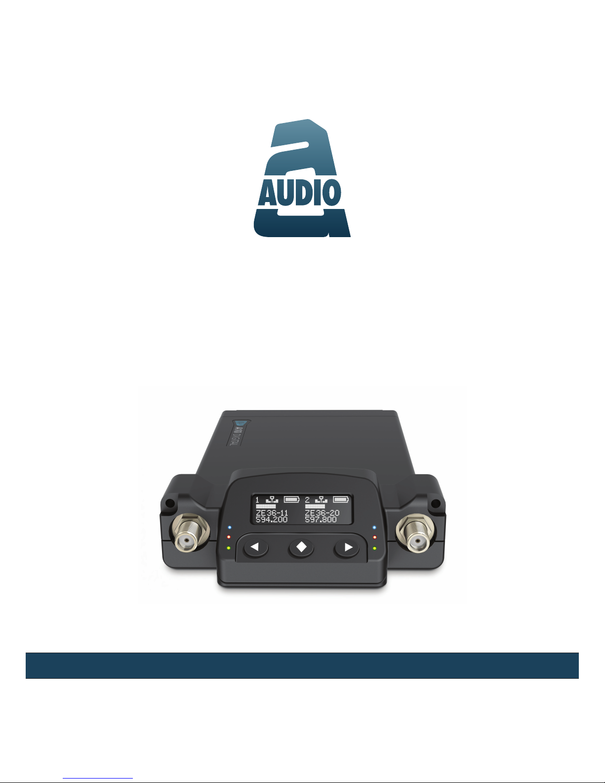
A10-RX
Digital Wireless Receiver
— User Guide —
Models: A10-RX-SL and A10-RX-XLR
Page 2

- 2 -
A10-RX User Guide
Copyright / Doc Rev History Info . . . . . 2
Overview . . . . . . . . . . . . . . . . . . 3
Key Features . . . . . . . . . . . . . . . 3
System Quickstart . . . . . . . . . . . . . 4
At the Receiver . . . . . . . . . . . . . . 4
At the Transmitter . . . . . . . . . . . . 4
At the Receiver . . . . . . . . . . . . . . 4
Connectors, Controls Description. . . . . 5
Powering . . . . . . . . . . . . . . . . . . 6
Channel Power LEDs . . . . . . . . . . 6
Main Display. . . . . . . . . . . . . . . . . 7
Two-Channel View . . . . . . . . . . . . 7
Single-Channel View . . . . . . . . . . 7
RF Signal Indicator LEDs . . . . . . . . 8
Display Orientation . . . . . . . . . . . 8
Selection Menu . . . . . . . . . . . . . . . 8
Main Menu . . . . . . . . . . . . . . . . 8
Outputs Sub-Menu . . . . . . . . . . . 9
Settings Sub-Menu . . . . . . . . . . . 9
System Sub-Menu . . . . . . . . . . . . 10
Basic Operation . . . . . . . . . . . . . . 10
Frequency Selection . . . . . . . . . . 10
Frequency Scanning . . . . . . . . . . 11
Partial Scanning, 25 MHz Increments . 11
Full Scan, 224 MHz . . . . . . . . . . . 11
Audio Output and Control . . . . . . . . 11
Analog Output . . . . . . . . . . . . . . 11
AES Digital Output . . . . . . . . . . . . 11
Antennae . . . . . . . . . . . . . . . . . 12
Firmware Updates . . . . . . . . . . . . . 12
A10-RX-XLR . . . . . . . . . . . . . . . 12
A10-RX-SL . . . . . . . . . . . . . . . . 12
Converting Between XLR & SL Mounts . . 12
Specifications . . . . . . . . . . . . . . . . 13
A10-RX-SL DB-25
Connector Pin Assignments . . . . . . 14
Certifications . . . . . . . . . . . . . . . . 14
Industry Canada Conformity . . . . . . 14
FCC Conformity . . . . . . . . . . . . . 15
Minimize RF Exposure . . . . . . . . . . 15
Frequency Tables . . . . . . . . . . . . . . 15
X Frequencies (6 MHz Per TV Channel) 15
Y Frequencies (7 MHz Per TV Channel) 17
Z Frequencies (8 MHz Per TV Channel) 18
Channel Assignments by Region . . . . 18
Table of Contents
Copyright / Doc Rev History Info
Part Number: 9279.000
Copyright © 2017 Audio Ltd. All rights reserved. | www.audioltd.com
7 Century Court, Tolpits Lane, Watford WD18 9RS, UK | info@audioltd.com
Revision Date Description
1A Dec 2017 Initial Publication
Page 3

- 3 -
A10-RX User Guide
Overview
The A10-RX two-channel Advanced Dual Diversity receiver is a portable, all-digital wireless re-
ceiver for the A10 system. It is designed to work with one or two A10-TX transmitters. It oers
224 MHz switching bandwidth and precision RF tracking lters in a lightweight, robust package.
Two models are available, the A10-RX-SL for slot-in connection and the A10-RX-XLR for
stand-alone operation with hardwired power and audio connections.
The A10 systems ultra-low 2 mS end-to-end delay and superb digital audio assures performance
that is indistinguishable from a hard-wired cable. The A10 system allows the user to operate up
to 20 channels in an 8 MHz TV channel, maximising spectrum eciency.
Key Features
Some key features of the A10-RX are:
• Two-channel, wideband receiver usable over the whole A10 system range
• Advanced Digital Diversity topology uses two complete RF receivers for each of the two
channels, four RF receivers total
• Easy and fast menu control
• Available in both slot (Uni-/SuperSlot) with the A10-RX-SL or stand-alone cabled version
with the A10-RX-XLR
• Analogue line-level or AES3 digital audio output
Page 4

- 4 -
A10-RX User Guide
System Quickstart
The A10 Digital Wireless System is easy to use. Follow the steps below for basic setup and operation.
At the Receiver
1. Fit the included straight and right-angled antennae to the A10-RX receiver.
2. Connect the receiver to a power source. It will immediately power on.
3. Using the scanning tool in the Selection menu nd an available open frequency. If multiple
wireless systems are in use, make certain to keep frequencies least 400 kHz apart.
4. Connect the audio output from channel 1, channel 2, or both to an audio input on a mixer,
recorder, camera, or PA system.
5. Ensure that the receiver audio output type and level are set based on the input type.
At the Transmitter
1. Attach the straight antenna to the A10-TX.
2. Attach an audio source to the 3-pin LEMO input connector.
3. Insert AA batteries into the A10-TX battery compartment and power on the unit with the red
On/O button.
4. Set the audio input type to set to match the connected input.
5. Set the transmitting frequency on the A10-TX match the frequency set on the A10-RX re-
ceiver channel.
6. Adjust the audio gain according to your environment and source, taking care not to overload
the signal. This is indicated by a red LED.
At the Receiver
1. Conrm that the Channel Power LED is solid blue.
2. Conrm that the RF Status LEDs and display indicate good RF strength.
3. Conrm that the audio level at the receiver corresponds to the audio connected to the
A10-TX input.
4. The system is now ready for use.
Page 5
- 5 -
A10-RX User Guide
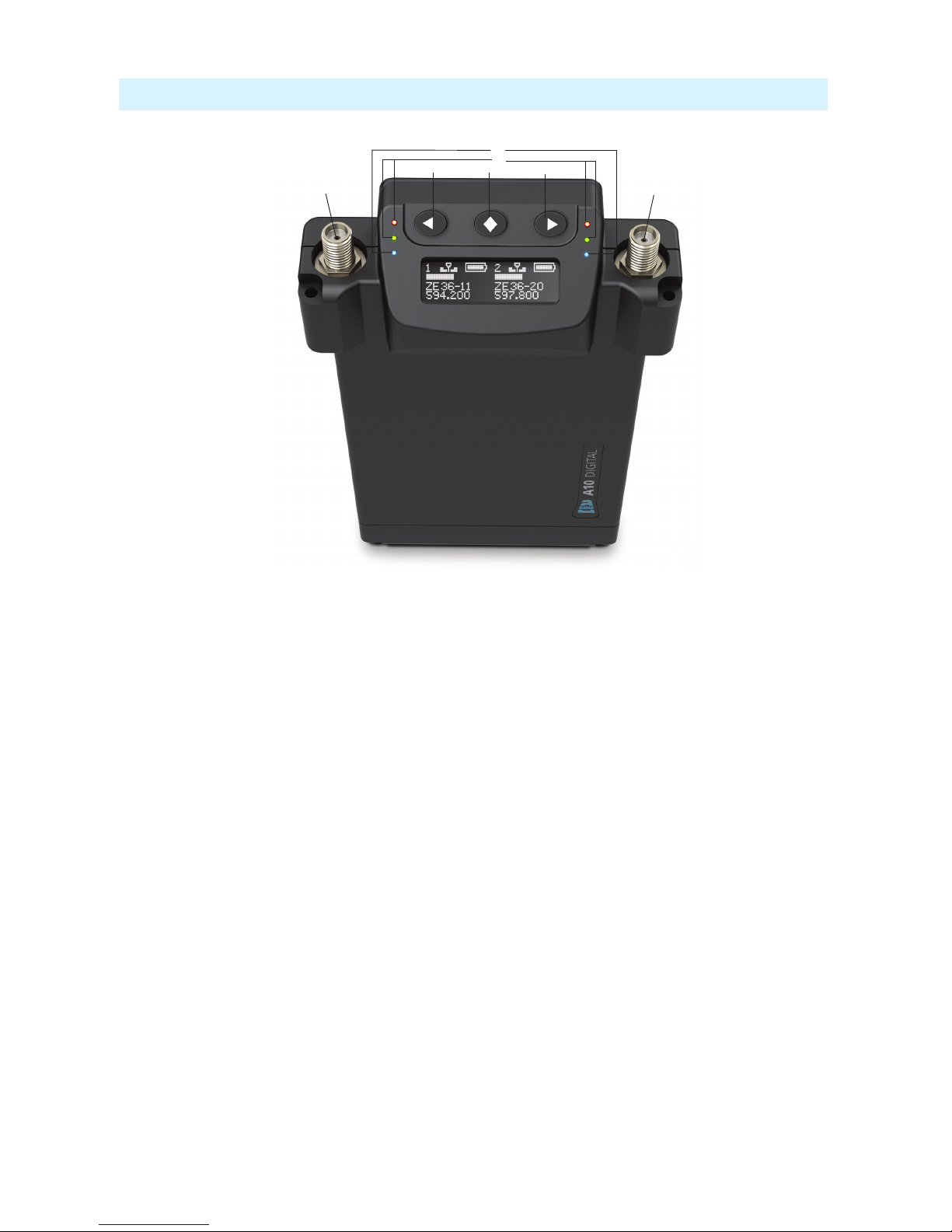
Connectors, Controls Description
2
1
4
3
7
6
5
Figure 1: A10-RX
1 -Antenna Socket
SMA connector, 50 ohm, connects to included 1/4-wave whip antenna.
2 -Channel Power LED
Illuminates blue when the channel’s receiver
circuitry is powered and operational.
Blue LED ashes when paired transmitter’s
battery is critically low or depleted.
3 -Green/Red RF Status LEDs
Indicates signal strength of received RF.
Green LED illuminates solid green with good
RF reception.
Red LED ashes red when RF signal strength
is poor. Illuminates red continuously when
RF level is no longer suitable or when RF
transmitter has been turned o.
4 -Left Button
Moves the selection in menu to the left, or
decrements values.
5 -Menu/Select Button
Enters the menu selection. Also used to select
options in the menu.
6 -Right Button
Moves the selection in the menu to the right,
or increments values.
7 -Antenna Socket
SMA connector, 50 ohm, connects to included 1/4-wave whip antenna.
8 -Display
OLED screen. The screen can be set to turn
o after a period of inactivity from the Selection menu (Main > Settings > Screensaver).
Page 6

- 6 -
A10-RX User Guide
Powering
The A10-RX-SL receives power over its D-sub connector. The A10-RX-XLR receives power
from its 4-pin Hirose female connector. The male Hirose connector is a power loop through.
When DC power is present, either at the D-sub connector or the Hirose 4-pin, the A10-RX is
powered. There are no additional power switches.
Channel Powering
Each of the two channels of the A10-RX can be powered on or o individually. When a channel
is powered down that portion of the A10-RX no longer draws power. If the A10-RX is going to
be used for a single wireless channel, best practice is to power down the unused channel. Channel powering is controlled in the Selection Menu (Main > System > Power).
Channel Power LEDs
The A10-RX has blue Channel Power LEDs for each of its two channels. When rst powering
the A10-RX without transmitters present, the LEDs illuminate indicating the receiver channel is
powered.
The receiver channel will connect, or pair, to an A10-TX transmitter that is powered on and set
to the receiver frequency. The Channel Power LED then shows the battery status of its associated
transmitter.
• Solid Blue - a solid blue LED indicates that the transmitter battery is in good condition.
• Flashing Blue - a ashing blue LED indicates when the transmitter battery level is low or
depleted.
When a paired transmitter is powered down, the blue LED continues to show the last condition
of the transmitter battery. If the transmitter is powered back on, or a new transmitter is activated
on the channel, that transmitter pairs with the receiver and its transmitter battery condition is
shown with the blue LED.
ª The LEDs change assignment based on the orientation of the display. Channel 1 is always
shown left of the display and channel 2 is always on the right.
Page 7

- 7 -
A10-RX User Guide
Main Display
When the receiver is rst powered on, the main display is in two-channel view.
Two-Channel View
The display shows channel 1 and channel 2 simultaneously. Parameters displayed include the RF
signal strength at each antenna, receiver frequency, audio level, and transmitter battery level.
1
2
3
4
5
6
1 -Channel 1 Settings
Bars indicates RF signal strength at each
antenna.
2 -Channel 2 Settings
Bars indicates RF signal strength at each
antenna.
3 -TX Battery Status
Battery icons indicate status of transmitters’
batteries.
4 -Audio Level
Each channel shows a horizontal meter for
audio levels.
5 -Frequency
Receiver frequency for each channel.
6 -Channel/Sub-channel Assignment
Displays region, channel, and sub-channel
frequency assignment for each transmitter.
ª X, Y, and Z regions are selected by the TV Channel Map
setting.
Single-Channel View
Pressing the Left or Right buttons when in two-channel view changes the display to a singlechannel view of channel 1 or 2, respectively.
In addition to the parameters shown in single channel view, the transmitter gain level is indicated in single channel view. Pressing the Right button again shows the A10-TX metadata for the
transmitter associated with the channel.
ª An asterisk next to the sub channel indicates that the set frequency is not directly on a
preassigned sub channel.
Page 8

- 8 -
A10-RX User Guide
RF Signal Indicator LEDs
The RF Signal LEDs oer an at-a-glance indication of RF performance. The LEDs to the left of
the display indicate channel 1 activity, whilst the LEDs to the right indicate channel 2 activity.
Each channel has one green LED and one red LED.
• Solid Green - indicates good RF reception.
• Flashing Red - warns that the RF level is low and that the receiving error rate is high, possi-
bly resulting in audio dropouts.
• Solid Red - when RF level no longer is suitable or when RF transmitter has been turned o.
ª The LEDs change assignment based on the orientation of the display. Channel 1 is always
shown left of the display and channel 2 is always on the right.
Display Orientation
The A10-RX Menu screen operates with its Menu buttons either below or above the display. This
is controlled in the Selection Menu (Main > Settings > Orientation).
Selection Menu
The A10-RX receiver is controlled through its main Selection menu. Enter the menu by rst selecting either the channel 1 receiver (Left button) or channel 2 receiver (Right button), then press
the centre Menu button. Once in the menu, the Left and Right buttons toggle among options, and
the Menu button makes the selection.
Main Menu
Selections Icon Description Channel
or Global
Options
Exit
Returns to the main display screen.
Frequency
Sets the transmitter’s frequency. Frequency
selection and channel increments change based on
the region of operation to which the unit is set.
Channel • TV Channel Increments
• Sub Channel Increments
• Tune: Frequency
Increments in 25 kHz steps
Outputs
Enters the Outputs sub menu. • Maximum Level
• Audio Polarity
• Mode
• Test Tone
Scan
Enters the scan function. Scanner indicates the RF
activity. Scans can either be in 25 MHz increments
or across the full range of the receiver.
Global • 1-10 - scans subsections of
the tuning range
• Full - scans entire tuning
range of system
Privacy
When active the transmitter sends its signal
encoded with a four-digit privacy key set at the
transmitter. The same four digit key needs to be set
on a receiver to receiver to receive the signal.
Channel • On - enter key
• O - encryption cleared, set
to 0000 to deactivate
Settings
Enters additional settings sub menu. • Screen Brightness
• Screensaver
• Orientation
• LEDs
• TV Channel Map
System
Enters additional settings sub menu • Power
• Restore
• Info
Page 9

- 9 -
A10-RX User Guide
Outputs Sub-Menu
Selections Icon Description Channel
or Global
Options
Exit
Returns to the main menu
Max Level
Selects the maximum analogue output level. Output
level based on a 0 dBFS signal sent from an A10-TX
transmitter.
Channel • +14 dBu
• +2 dBu
• -10 dBu
• -22 dBu
Audio Polarity
Selects the polarity of the balanced output signal. Channel • Normal
• Inverted
Mode
Chooses the audio output type of the A10-RX.
When the A10-RX is set to AES the channel 2 XLR
connection is not used.
Global • Analogue
• AES
Test Tone
Activates a 1 kHz tone oscillator sent directly to the
outputs.
ª This disrupts the output from a linked A10-TX
transmitter.
Global • -18 dB
• -12 dB
• -6 dB
• 0 dB
Settings Sub-Menu
ª All setting are Global.
Selections Icon Description Options
Exit
Returns to the main menu
Screen Brightness
Sets the brightness of the OLED screen. Five increments, 1–5, 5 is brightest
Screensaver
Sets the duration, in seconds, how long the screen
remains on after a button press. O keeps the screen
on continuously with no screensaver.
• O - display remains on when unit
is powered
• 5 sec
• 30 sec
• 120 sec
Orientation
Sets the operating orientation of the menu screen and
LEDs. The A10-RX can be used in an orientation with
the buttons below the screen (normal), or with the
buttons to the top (ipped).
• Normal
• Flipped
LEDs
When set to On the LEDs remain illuminated. O
deactivates the LEDs.
• On
• O
TV Ch Map
Selects the TV channel spacing in MHz to ensure
channel selection corresponds to a specic geographic
region. See frequency chart.
• X – 6 MHz
• Y – 7 MHz
• Z – 8 MHz
Page 10

- 10 -
A10-RX User Guide
System Sub-Menu
ª All settings are Global.
Selections Icon Description Options
Exit
Returns the main menu
Power
Turns power to the RF receiver for each of the two channels
on and o.
• 1 - channel 1 only
• 1 and 2 - both channel 1 and 2
• 2 - channel 2 only
• O - receiver circuits o
Restore
The restore function allows the user to reset the A10-RX to
the factory default settings.
ª Restore sets the TV Channel Map to region Z. Select the
current region in your locality before proceeding.
Info
Shows numerous attributes of the transmitter. • Serial Number
• Firmware Revision
• Frequency Band
Basic Operation
Frequency Selection
The A10 Digital Wireless System operates in the UHF frequency band from 470 to 694 MHz.
The A10-RX can tune across the entire range of the system.
Because the A10 digital RF transmission is inherently immune to intermodulation multiple A10
Digital Wireless systems can be used simultaneously on nearby adjacent frequencies without
worry of intermodulation interference. Systems can be used together when separated by at least
400 kHz.
Manually Setting Channel, Sub Channel, Frequency
To simplify frequency selection, frequencies are divided into channels and sub channels. The
specic frequencies corresponding to channels and sub channels depends on the setting of the
TV Channel Mapping (Main > Settings > TV Ch Map). Three options are available, 6, 7, and 8
MHz spacing, X, Y, and Z respectively. These three settings generally correspond to three main
geographic regions, the Americas, Australia/New Zealand, and Europe, respectively. For more
information, see Channel Assignments by Region.
• Channel - corresponds to broadcast television channels used in a geographic region. Depending on the selected channel mapping, channels cover 6, 7, or 8 MHz.
• Sub Channel - channels are divided in 400 kHz increments called sub channels to speed up
frequency selection. The number of sub channels depends on the channel mapping selected.
• Frequency - specic frequencies within the receivers tuning range can be selected in 25
kHz increments. When a selected frequency does not correspond with a channel/sub channel
mapping, an asterisk character (*) is shown in the display adjacent to channel/sub channel
assignment below the frequency shown.
To change TV channels:
1. Use the Left button to highlight the TV Channel.
2. Press the centre menu to select the TV channel.
3. Select the sub channel until the desired sub-channel is selected.
Page 11

- 11 -
A10-RX User Guide
ª Remember, for a given channel / sub channel, the actual frequency will change depending on
the TV Channel Mapping setting.
See the Frequency Tables in this guide for a complete list of frequencies corresponding to the
channel and sub channel selections.
Frequency Scanning
The frequency scanning tool uses the radios in the A10-RX to measure and display RF activity
within the system’s tuning range. This allows a user to nd frequencies with low RF activity
suitable for system operation. The scan tool operates over the full 224 MHz bandwidth of the
receiver. Enter the scanner from the Selection Menu Main > Scan.
ª Audio from channel 1 and channel 2 is muted when the scan tool is active.
To initiate a scan press the >> button. The scan will start, working from lower frequencies to
higher frequencies. The cursor can be seen to move along the screen denoting the current posi-
tion of the scan. The scan can be stopped by pressing the Left button.
Selecting the > button allows the user to manually step through in 400 kHz steps at a time.
Selecting the << button allows the user to automatically scan backwards, and similarly selecting
the < button allows the user to manually step lower in frequency in 400 kHz steps.
Partial Scanning, 25 MHz Increments
In partial scanning mode the receiver scans a 25 MHz range. This partial scan improves the
resolution of the scan over a full scan. The ten partial scans cover the following ranges:
1 - 470-495 MHz
2 - 492-517 MHz
3 - 515-540 MHz
4 - 537-562 MHz
5 - 559-584 MHz
6 - 581-606 MHz
7 - 603-628 MHz
8 - 626-651 MHz
9 - 648-673 MHz
10 - 669-694 MHz
Full Scan, 224 MHz
The full receiver bandwidth of 224 MHz can also be scanned.
Audio Output and Control
The A10-RX outputs either analogue line level or AES3 digital audio. This global setting applies
to both channel outputs.
Analogue Output
When set to analogue in the Selection Menu the A10-RX outputs low-impedance, balanced
line level audio. It is designed to connect to balanced or unbalanced line level inputs. To un-
balance the output, oat pin-3.
AES Digital Output
When set to AES output in the Selection Menu the A10-RX outputs two-channel AES3 at 24bit, 48 kHz. Channel 1 output appears at AES left, channel 2 appears at AES right.
With the A10-RX-XLR the channel 1 XLR connector is used for AES3 output. The channel 2
XLR connector is not active when set to AES output.
Page 12

- 12 -
A10-RX User Guide
Antennae
The SMA antenna connector is used to mount the included 1/4-wave whip antenna. For specialty
applications external, high-gain receiving antennae can be attached to the SMA connector.
ª Ensure that the antennae used are built for the correct frequency.
For best operation and reception power with the included 1/4-wave antenna, keep it in the free
eld, away from direct contact with the wearer’s body. When multiple wireless systems are in
use keep transmitters separated by at least 1/2-wave distance of the transmitted frequency.
Firmware Updates
From time to time Audio Ltd. issues new rmware for the A10-RX receiver. Make certain to register your Audio Ltd. product at the Audio Ltd. website to receive rmware update notications.
A10-RX-XLR
The Audio Ltd. software utility Mic2Wav, which is available as a free download from the Audio
Ltd. website, includes a receiver rmware update tool.
To update rmware:
1. Download new rmware update le from the Audio Ltd. website.
2. Launch the Mic2Wav application on a Windows-based computer.
3. Power on the A10-RX-XLR.
4. Connect the receiver (microUSB) to the computer’s USB port.
5. From within the application, select File > Update RX and then select the rmware update le
(.PRG) to install.
6. Follow the on-screen prompts.
A10-RX-SL
At present, updating the rmware on the A10-RX-SL requires converting from SL to XLR.
Converting Between XLR and SL Mounts
The A10-RX receiver is modular in design. With the correct accessories—either the A-SL or the
A-XLR adapters—the A10-RX-SL slot receiver and A10-RX-XLR cabled receiver can be converted between each type.
• The A-SL accessory is a 25-Pin D-Type Uni/Superslot adapter, and comes with the A-PLATE
spacer.
• The A-XLR accessory is an XLR and power cable adapter.
To convert from an A10-RX-SL to an A10-RX-XLR:
1. Remove the four perimeter screws. Do not remove the two screws on either side of the 25pin D-Type connector.
Page 13

- 13 -
A10-RX User Guide
2. Remove the A-SL accessory.
3. Position the A-XLR accordingly, and replace screws.
ª Complete the above procedure in reverse to convert from A10-RX-XLR to A10-RX-SL.
Page 14

- 14 -
A10-RX User Guide
Specifications
Frequency Range
World Models:
A10-RX-SL (470–694 MHz)
A10-RX-XLR (470–694 MHz)
Transmitters are tunable in 25 kHz steps.
U.S. Only Models:
A10-RX-SL-US (470–608 MHz)
A10-RX-XLR-US (470–608 MHz)
Modulation Mode
Audio Ltd. proprietary digital RF modulation
Digital Audio Codec
Audio Ltd. proprietary, high-performance digital encoding algorithm
Audio Frequency Response
20 Hz–20 kHz
Maximum Output Level
+14 dBu, +2 dBu, -10 dBu, or -22 dBu, menu-selectable, with a 0 dBFS signal at the transmitter
input, 130 ohms impedance
Digital Audio Output
AES3 balanced connection, 110 ohms, left=channel 1, right=channel 2
Menu and Controls
OLED menu display, 3 button navigation
Privacy
User settable 4-digit PIN, Audio Ltd. proprietary
Powering
6–16 VDC, approx. 3 W with one receiver active, approx. 4.4 W with two receivers active
Operating Temperature
Range
-10 °C to +55 °C
Weight and Dimensions
108 g, 83 x 64 x 18 mm
Page 15

- 15 -
A10-RX User Guide
A10-RX-SL DB-25 Connector Pin Assignments
The illustration below shows the pin assignments of the A10-RX-SL when viewing the bottom connector.
DB-25
Pin
Name Description
1
Ground Ground connection
2
Ch 1+ analogue / Ch 1,2
AES +
Ch 1 + analogue audio out, +2 dBu level (+/- 0.5 dB), balanced. Alternately, Ch1
and Ch 2 AES3+ (balanced, 110 ohm, transformerless).
3
Ch 1 - analogue / Ch 1,2
AES -
Ch 1 - analogue audio out, +2 dBu level (+/- 0.5 dB), balanced. Alternately, Ch 1
and Ch 2 AES3- (balanced, 110 ohm, transformerless).
4
Ground Ground for power
5
6-18 VDC Power supply, 6.0-18.0 V, 6 W max.
6
no connection
7
no connection
8
no connection
9
no connection
10
no connection
11
no connection
12
no connection
13
Ground Ground connection
14
Ground Ground connection
15
Ch 2+ analogue Ch 2 + analogue audio out, +2 dBu level (+/- 0.5 dB), balanced.
16
Ch 2- analogue Ch 2 - analogue audio out, +2 dBu level (+/- 0.5 dB), balanced.
17
no connection
18
no connection
19
no connection
20
no connection
21
no connection
22
UART transmit (0/3.3V) UART from A10-RX. 0/3.3V signaling.
23
UART receive (0/3.3V) UART to A10-RX. 0/3.3 V signaling.
24
no connection
25
Ground Ground connection
Page 16

- 16 -
A10-RX User Guide
Certifications
Industry Canada Conformity
EN: This device complies with Industry Canada RSS-210. Operation is subject to the following
two conditions: (1) this device may not cause interference, and (2) this device must accept any
interference, including interference that may cause undesired operation of the device.
FR :Le présent appareil est conforme aux CNR d’Industrie Canada applicables aux appareils
radio RSS-210. L’exploitation est autorisée aux deux conditions suivantes: (1) l’appareil ne doit
pas produire de brouillage, et (2) l’utilisateur de l’appareil doit accepter tout brouillage radioélec-
trique subi, même si le brouillage est susceptible d’en compromettre le fonctionnement.
FCC Conformity
The A10-TX transmitter complies with the following requirements:
FCC (Federal Communications Commission) Part 74
Operation is subject to the following two conditions:
(1) This device may not cause harmful interference, and
(2) This device must accept any interference received, including interference that may cause
undesired operations.
Changes or modication not expressly approved.
A10-TX frequency ranges supplied for use in USA
A10-TX transmitters available for sale in the U. S. can tune over a switching bandwidth of up to
100 MHz. e frequency ranges are listed below:
• 470.1–547.9 MHz
• 518.1–607.9 MHz
ª Frequency range 608–614 MHz is forbidden for use in US.
ª Warning! Any modications or changes made to this device, unless explicitly approved by
Audio Ltd. may invalidate the authorisation of this device. Operation of an unauthorised
device is prohibited under Section 302 of the Communications act of 1934, as amended,
and Subpart 1 of Part 2 of Chapter 47 of the Code of Federal Regulations.
Minimize RF Exposure
To avoid the possibility of exceeding the FCC RF exposure limits, it is recommended that the
transmitter or attached microphone is kept at a minimum distance of 13 mm (0.5 inch) away
from the head or body during normal operation.
Page 17

- 17 -
A10-RX User Guide
Frequency Tables
The A10-TX oers preselected frequencies based on channels and sub channels. Three sets of
frequencies are available based on either 6, 7, or 8 MHz channel bandwidth. Select the channel
bandwidth based on the geographic region where the unit is operating.
X Frequencies (6 MHz Per TV Channel)
The chart below shows all frequencies available for the A10 wireless system. Not all channels
are available on all transmitters.
Sub Channel
1 2 3 4 5 6 7 8 9 10 11 12 13 14 15
Channel
14
470.2 470.6 471 471.4 471.8 472.2 472.6 473 473.4 473.8 474.2 474.6 475 475.4 475.8
15
476.2 476.6 477 477.4 477.8 478.2 478.6 479 479.4 479.8 480.2 480.6 481 481.4 481.8
16
482.2 482.6 483 483.4 483.8 484.2 484.6 485 485.4 485.8 486.2 486.6 487 487.4 487.8
17
488.2 488.6 489 489.4 489.8 490.2 490.6 491 491.4 491.8 492.2 492.6 493 493.4 493.8
18
494.2 494.6 495 495.4 495.8 496.2 496.6 497 497.4 497.8 498.2 498.6 499 499.4 499.8
19
500.2 500.6 501 501.4 501.8 502.2 502.6 503 503.4 503.8 504.2 504.6 505 505.4 505.8
20
506.2 506.6 507 507.4 507.8 508.2 508.6 509 509.4 509.8 510.2 510.6 511 511.4 511.8
21
512.2 512.6 513 513.4 513.8 514.2 514.6 515 515.4 515.8 516.2 516.6 517 517.4 517.8
22
518.2 518.6 519 519.4 519.8 520.2 520.6 521 521.4 521.8 522.2 522.6 523 523.4 523.8
23
524.2 524.6 525 525.4 525.8 526.2 526.6 527 527.4 527.8 528.2 528.6 529 529.4 529.8
24
530.2 530.6 531 531.4 531.8 532.2 532.6 533 533.4 533.8 534.2 534.6 535 535.4 535.8
25
536.2 536.6 537 537.4 537.8 538.2 538.6 539 539.4 539.8 540.2 540.6 541 541.4 541.8
26
542.2 542.6 543 543.4 543.8 544.2 544.6 545 545.4 545.8 546.2 546.6 547 547.4 547.8
27
548.2 548.6 549 549.4 549.8 550.2 550.6 551 551.4 551.8 552.2 552.6 553 553.4 553.8
28
554.2 554.6 555 555.4 555.8 556.2 556.6 557 557.4 557.8 558.2 558.6 559 559.4 559.8
29
560.2 560.6 561 561.4 561.8 562.2 562.6 563 563.4 563.8 564.2 564.6 565 565.4 565.8
30
566.2 566.6 567 567.4 567.8 568.2 568.6 569 569.4 569.8 570.2 570.6 571 571.4 571.8
31
572.2 572.6 573 573.4 573.8 574.2 574.6 575 575.4 575.8 576.2 576.6 577 577.4 577.8
32
578.2 578.6 579 579.4 579.8 580.2 580.6 581 581.4 581.8 582.2 582.6 583 583.4 583.8
33
584.2 584.6 585 585.4 585.8 586.2 586.6 587 587.4 587.8 588.2 588.6 589 589.4 589.8
34
590.2 590.6 591 591.4 591.8 592.2 592.6 593 593.4 593.8 594.2 594.6 595 595.4 595.8
35
596.2 596.6 597 597.4 597.8 598.2 598.6 599 599.4 599.8 600.2 600.6 601 601.4 601.8
36
602.2 602.6 603 603.4 603.8 604.2 604.6 605 605.4 605.8 606.2 606.6 607 607.4 607.8
37
608.2 608.6 609 609.4 609.8 610.2 610.6 611 611.4 611.8 612.2 612.6 613 613.4 613.8
38
614.2 614.6 615 615.4 615.8 616.2 616.6 617 617.4 617.8 618.2 618.6 619 619.4 619.8
39
620.2 620.6 621 621.4 621.8 622.2 622.6 623 623.4 623.8 624.2 624.6 625 625.4 625.8
40
626.2 626.6 627 627.4 627.8 628.2 628.6 629 629.4 629.8 630.2 630.6 631 631.4 631.8
41
632.2 632.6 633 633.4 633.8 634.2 634.6 635 635.4 635.8 636.2 636.6 637 637.4 637.8
42
638.2 638.6 639 639.4 639.8 640.2 640.6 641 641.4 641.8 642.2 642.6 643 643.4 643.8
43
644.2 644.6 645 645.4 645.8 646.2 646.6 647 647.4 647.8 648.2 648.6 649 649.4 649.8
44
650.2 650.6 651 651.4 651.8 652.2 652.6 653 653.4 653.8 654.2 654.6 655 655.4 655.8
45
656.2 656.6 657 657.4 657.8 658.2 658.6 659 659.4 659.8 660.2 660.6 661 661.4 661.8
46
662.2 662.6 663 663.4 663.8 664.2 664.6 665 665.4 665.8 666.2 666.6 667 667.4 667.8
47
668.2 668.6 669 669.4 669.8 670.2 670.6 671 671.4 671.8 672.2 672.6 673 673.4 673.8
48
674.2 674.6 675 675.4 675.8 676.2 676.6 677 677.4 677.8 678.2 678.6 679 679.4 679.8
49
680.2 680.6 681 681.4 681.8 682.2 682.6 683 683.4 683.8 684.2 684.6 685 685.4 685.8
50
686.2 686.6 687 687.4 687.8 688.2 688.6 689 689.4 689.8 690.2 690.6 691 691.4 691.8
51
692.2 692.6 693 693.4 693.8 694.2 694.6 695 695.4 695.8 696.2 696.6 697 697.4 697.8
Page 18

- 18 -
A10-RX User Guide
Y Frequencies (7 MHz Per TV Channel)
Sub Channels
1 2 3 4 5 6 7 8 9 10 11 12 13 14 15 16 17
Channels
22
485.3 485.7 486.1 486.3 486.7 487.1 487.3 487.7 488.1 488.3 488.7 489.1 489.3 489.7 490.1 490.3 490.7
23
492.3 492.7 493.1 493.3 493.7 494.1 494.3 494.7 495.1 495.3 495.7 496.1 496.3 496.7 497.1 497.3 497.7
24
499.3 499.7 500.1 500.5 500.7 501.1 501.3 501.7 502.1 502.5 502.7 503.1 503.3 503.7 504.1 504.5 504.7
25
506.3 506.7 507.1 507.5 507.9 508.3 508.3 508.7 509.1 509.5 509.9 510.3 510.3 510.7 511.1 511.5 511.9
26
513.3 513.7 514.1 514.5 514.9 515.3 515.3 515.7 516.1 516.5 516.9 517.3 517.3 517.7 518.1 518.5 518.9
27
520.3 520.7 521.1 521.5 521.9 522.3 522.3 522.7 523.1 523.5 523.9 524.3 524.3 524.7 525.1 525.5 525.9
28
527.3 527.7 528.1 528.5 528.9 529.3 529.3 529.7 530.1 530.5 530.9 531.3 531.3 531.7 532.1 532.5 532.9
29
534.3 534.7 535.1 535.5 535.9 536.3 536.3 536.7 537.1 537.5 537.9 538.3 538.3 538.7 539.1 539.5 539.9
30
541.3 541.7 542.1 542.5 542.9 543.3 543.3 543.7 544.1 544.5 544.9 545.3 545.3 545.7 546.1 546.5 546.9
31
548.3 548.7 549.1 549.5 549.9 550.3 550.3 550.7 551.1 551.5 551.9 552.3 552.3 552.7 553.1 553.5 553.9
32
555.3 555.7 556.1 556.5 556.9 557.3 557.3 557.7 558.1 558.5 558.9 559.3 559.3 559.7 560.1 560.5 560.9
33
562.3 562.7 563.1 563.5 563.9 564.3 564.3 564.7 565.1 565.5 565.9 566.3 566.3 566.7 567.1 567.5 567.9
34
569.3 569.7 570.1 570.5 570.9 571.3 571.3 571.7 572.1 572.5 572.9 573.3 573.3 573.7 574.1 574.5 574.9
35
576.3 576.7 577.1 577.5 577.9 578.3 578.3 578.7 579.1 579.5 579.9 580.3 580.3 580.7 581.1 581.5 581.9
36
583.3 583.7 584.1 584.5 584.9 585.3 585.3 585.7 586.1 586.5 586.9 587.3 587.3 587.7 588.1 588.5 588.9
37
590.3 590.7 591.1 591.5 591.9 592.3 592.3 592.7 593.1 593.5 593.9 594.3 594.3 594.7 595.1 595.5 595.9
38
597.3 597.7 598.1 598.5 598.9 599.3 599.3 599.7 600.1 600.5 600.9 601.3 601.3 601.7 602.1 602.5 602.9
39
604.3 604.7 605.1 605.5 605.9 606.3 606.3 606.7 607.1 607.5 607.9 608.3 608.3 608.7 609.1 609.5 609.9
40
611.3 611.7 612.1 612.5 612.9 613.3 613.3 613.7 614.1 614.5 614.9 615.3 615.3 615.7 616.1 616.5 616.9
41
618.3 618.7 619.1 619.5 619.9 620.3 620.3 620.7 621.1 621.5 621.9 622.3 622.3 622.7 623.1 623.5 623.9
42
625.3 625.7 626.1 626.5 626.9 627.3 627.3 627.7 628.1 628.5 628.9 629.3 629.3 629.7 630.1 630.5 630.9
43
632.3 632.7 633.1 633.5 633.9 634.3 634.3 634.7 635.1 635.5 635.9 636.3 636.3 636.7 637.1 637.5 637.9
44
639.3 639.7 640.1 640.5 640.9 641.3 641.3 641.7 642.1 642.5 642.9 643.3 643.3 643.7 644.1 644.5 644.9
45
646.3 646.7 647.1 647.5 647.9 648.3 648.3 648.7 649.1 649.5 649.9 650.3 650.3 650.7 651.1 651.5 651.9
46
653.3 653.7 654.1 654.5 654.9 655.3 655.3 655.7 656.1 656.5 656.9 657.3 657.3 657.7 658.1 658.5 658.9
47
660.3 660.7 661.1 661.5 661.9 662.3 662.3 662.7 663.1 663.5 663.9 664.3 664.3 664.7 665.1 665.5 665.9
48
667.3 667.7 668.1 668.5 668.9 669.3 669.3 669.7 670.1 670.5 670.9 671.3 671.3 671.7 672.1 672.5 672.9
49
674.3 674.7 675.1 675.5 675.9 676.3 676.3 676.7 677.1 677.5 677.9 678.3 678.3 678.7 679.1 679.5 679.9
50
681.3 681.7 682.1 682.5 682.9 683.3 683.3 683.7 684.1 684.5 684.9 685.3 685.3 685.7 686.1 686.5 686.9
51
688.3 688.7 689.1 689.5 689.9 690.3 690.3 690.7 691.1 691.5 691.9 692.3 692.3 692.7 693.1 693.5 693.9
Page 19

- 19 -
A10-RX User Guide
Z Frequencies (8 MHz Per TV Channel)
Sub Channels
1 2 3 4 5 6 7 8 9 10 11 12 13 14 15 16 17 18 19 20
Channels
21
470.2 470.6 471.0 471.4 471.8 472.2 472.6 473.0 473.4 473.8 474.2 474.6 475.0 475.4 475.8 476.2 476.6 477.0 477.4 477.8
22
478.2 478.6 479.0 479.4 479.8 480.2 480.6 481.0 481.4 481.8 482.2 482.6 483.0 483.4 483.8 484.2 484.6 485.0 485.4 485.8
23
486.2 486.6 487.0 487.4 487.8 488.2 488.6 489.0 489.4 489.8 490.2 490.6 491.0 491.4 491.8 492.2 492.6 493.0 493.4 493.8
24
494.2 494.6 495.0 495.4 495.8 496.2 496.6 497.0 497.4 497.8 498.2 498.6 499.0 499.4 499.8 500.2 500.6 501.0 501.4 501.8
25
502.2 502.6 503.0 503.4 503.8 504.2 504.6 505.0 505.4 505.8 506.2 506.6 507.0 507.4 507.8 508.2 508.6 509.0 509.4 509.8
26
510.2 510.6 511.0 511.4 511.8 512.2 512.6 513.0 513.4 513.8 514.2 514.6 515.0 515.4 515.8 516.2 516.6 517.0 517.4 517.8
27
518.2 518.6 519.0 519.4 519.8 520.2 520.6 521.0 521.4 521.8 522.2 522.6 523.0 523.4 523.8 524.2 524.6 525.0 525.4 525.8
28
526.2 526.6 527.0 527.4 527.8 528.2 528.6 529.0 529.4 529.8 530.2 530.6 531.0 531.4 531.8 532.2 532.6 533.0 533.4 533.8
29
534.2 534.6 535.0 535.4 535.8 536.2 536.6 537.0 537.4 537.8 538.2 538.6 539.0 539.4 539.8 540.2 540.6 541.0 541.4 541.8
30
542.2 542.6 543.0 543.4 543.8 544.2 544.6 545.0 545.4 545.8 546.2 546.6 547.0 547.4 547.8 548.2 548.6 549.0 549.4 549.8
31
550.2 550.6 551.0 551.4 551.8 552.2 552.6 553.0 553.4 553.8 554.2 554.6 555.0 555.4 555.8 556.2 556.6 557.0 557.4 557.8
32
558.2 558.6 559.0 559.4 559.8 560.2 560.6 561.0 561.4 561.8 562.2 562.6 563.0 563.4 563.8 564.2 564.6 565.0 565.4 565.8
33
566.2 566.6 567.0 567.4 567.8 568.2 568.6 569.0 569.4 569.8 570.2 570.6 571.0 571.4 571.8 572.2 572.6 573.0 573.4 573.8
34
574.2 574.6 575.0 575.4 575.8 576.2 576.6 577.0 577.4 577.8 578.2 578.6 579.0 579.4 579.8 580.2 580.6 581.0 581.4 581.8
35
582.2 582.6 583.0 583.4 583.8 584.2 584.6 585.0 585.4 585.8 586.2 586.6 587.0 587.4 587.8 588.2 588.6 589.0 589.4 589.8
36
590.2 590.6 591.0 591.4 591.8 592.2 592.6 593.0 593.4 593.8 594.2 594.6 595.0 595.4 595.8 596.2 596.6 597.0 597.4 597.8
37
598.2 598.6 599.0 599.4 599.8 600.2 600.6 601.0 601.4 601.8 602.2 602.6 603.0 603.4 603.8 604.2 604.6 605.0 605.4 605.8
38
606.2 606.6 607.0 607.4 607.8 608.2 608.6 609.0 609.4 609.8 610.2 610.6 611.0 611.4 611.8 612.2 612.6 613.0 613.4 613.8
39
614.2 614.6 615.0 615.4 615.8 616.2 616.6 617.0 617.4 617.8 618.2 618.6 619.0 619.4 619.8 620.2 620.6 621.0 621.4 621.8
40
622.2 622.6 623.0 623.4 623.8 624.2 624.6 625.0 625.4 625.8 626.2 626.6 627.0 627.4 627.8 628.2 628.6 629.0 629.4 629.8
41
630.2 630.6 631.0 631.4 631.8 632.2 632.6 633.0 633.4 633.8 634.2 634.6 635.0 635.4 635.8 636.2 636.6 637.0 637.4 637.8
42
638.2 638.6 639.0 639.4 639.8 640.2 640.6 641.0 641.4 641.8 642.2 642.6 643.0 643.4 643.8 644.2 644.6 645.0 645.4 645.8
43
646.2 646.6 647.0 647.4 647.8 648.2 648.6 649.0 649.4 649.8 650.2 650.6 651.0 651.4 651.8 652.2 652.6 653.0 653.4 653.8
44
654.2 654.6 655.0 655.4 655.8 656.2 656.6 657.0 657.4 657.8 658.2 658.6 659.0 659.4 659.8 660.2 660.6 661.0 661.4 661.8
45
662.2 662.6 663.0 663.4 663.8 664.2 664.6 665.0 665.4 665.8 666.2 666.6 667.0 667.4 667.8 668.2 668.6 669.0 669.4 669.8
46
670.2 670.6 671.0 671.4 671.8 672.2 672.6 673.0 673.4 673.8 674.2 674.6 675.0 675.4 675.8 676.2 676.6 677.0 677.4 677.8
47
678.2 678.6 679.0 679.4 679.8 680.2 680.6 681.0 681.4 681.8 682.2 682.6 683.0 683.4 683.8 684.2 684.6 685.0 685.4 685.8
48
686.2 686.6 687.0 687.4 687.8 688.2 688.6 689.0 689.4 689.8 690.2 690.6 691.0 691.4 691.8 692.2 692.6 693.0 693.4 693.8
Channel Assignments by Region
Region AL Frequency Region
North America, South Korea, Taiwan, Philippines X
UK and Western Europe , Greenland, Asia, Africa Z
Australia and New Zealand Y
Japan X
Taiwan X
China X
For further information, contact Audio Ltd or your local distributor
Copyright © 2017 Audio Ltd. All rights reserved. | www.audioltd.com
7 Century Court, Tolpits Lane, Watford WD18 9RS, UK | info@audioltd.com
Page 20

- 20 -
A10-RX User Guide
 Loading...