

Page 1

Manual v2.0
Monitor Controller
Page 2
Contents
Welcome to your
new Audient Nero
Monitor Controller
To help get you started please visit
audient.com/nero
to download the supporting
documentation and brochures for our
product range.
The 12V DC power supply comes with
interchangeable UK, EU, US and Australian
Socket Adaptors and will work across a
broad range of Mains Voltages, making
Nero globally portable.
Inside the box:
• Nero
• 12V Switch Mode Power Supply with
Regional Adaptors
• Quick Start Guide
Features include:
• 4 x Stereo Analogue sources
- 2 x Line Level Inputs
- 1 x Dedicated Cue Mix Input
- 1 x Aux Input (RCA or Mini Jack)
• Optical & Coaxial S/PDIF Inputs
• 3 x Stereo Speaker Outputs
• 1 x Assignable Sub Output
• 4 x Headphone Outputs with flexible
routing
• Smart Touchpoints for user
customisation
• Talkback Input
• Internal Microphone
• External Talkback Input
• Dim, Cut, Mono & Polarity Monitor
Controls
Contents
Nero Overview
Safety Information
Declaration of Conformities
Setup Diagrams
Hardware Features:
Power Switch
Inputs
Outputs
Routing
Input Selection
Speaker Output Selection
Volume Control
Monitoring Functions
Talkback
Saving your Routing
Factory Reset
Smart Touchpoints
Speaker Level Matching
Smart Mono Mode
Assignable Sub
User Defined Dim
Talkback Routing
4
5
7
8
12
13
14
15
16
16
17
18
18
19
20
20
21
21
22
22
23
23
Signal Flow Diagrams
Technical Specifications
Warranty
Contact
Service
Glossary
24
26
27
28
29
30
3
Page 3
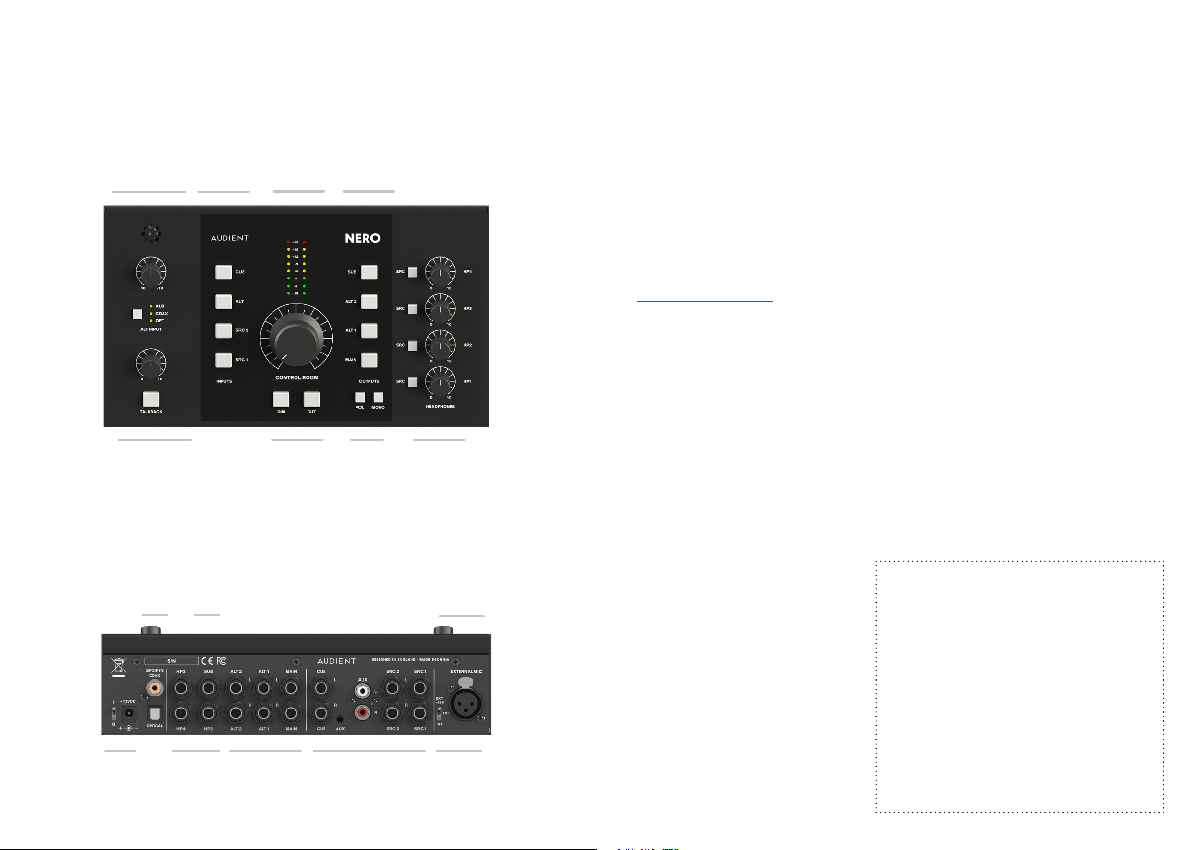
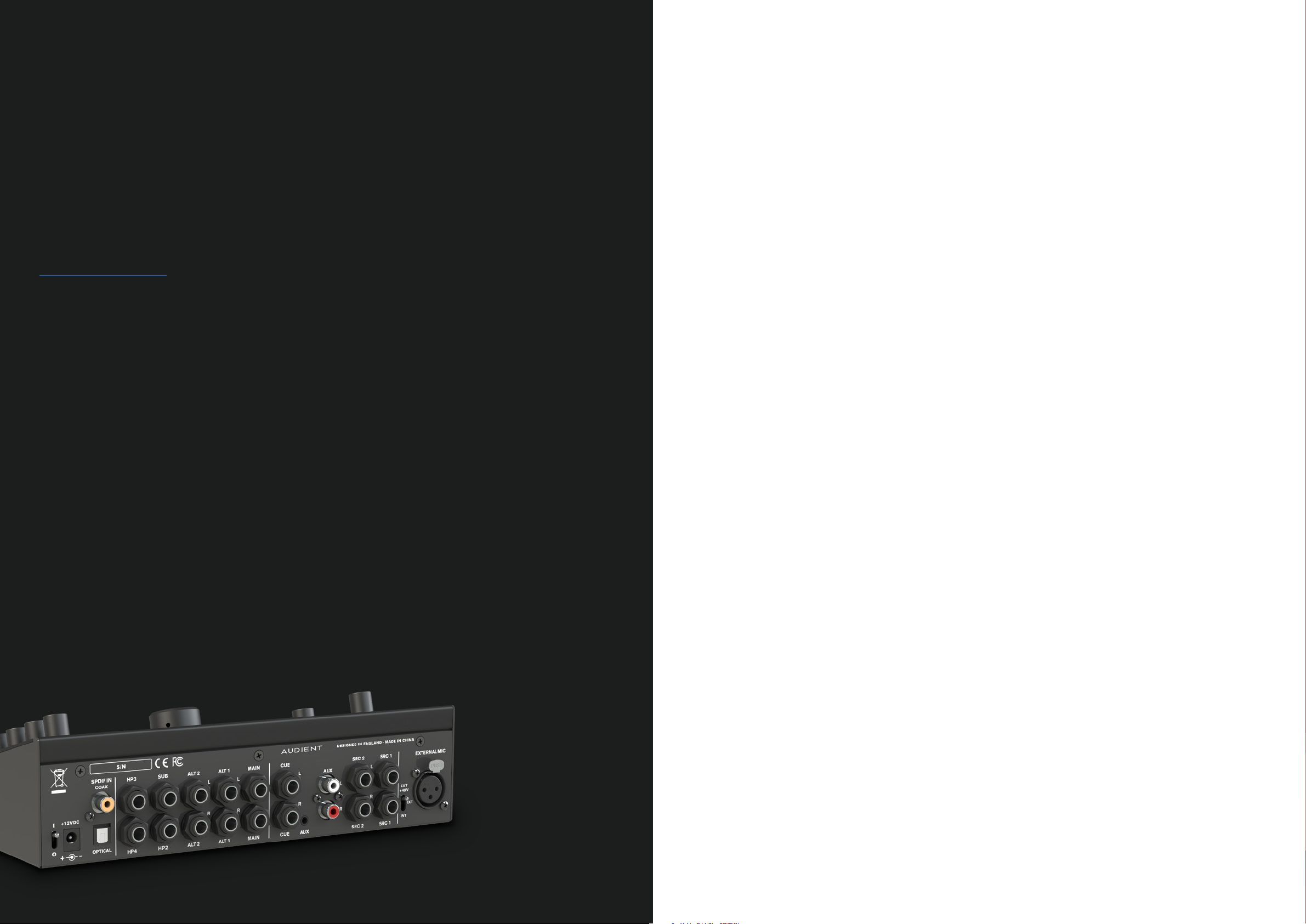
Nero Overview
Safety Information
Aux Input Trim
and Alt Input
Selection
Input
Source
Selection
Speaker
Volume &
Input Meters
Speaker
Output
Selection
Important Safety Instructions
Please read all of these instructions and save them for later reference before connecting
the DC power adapter to the mains and powering up Nero.
To prevent electrical shock and fire hazard follow all instructions on the 12VDC power supply. Nero
itself does not operate with any high voltage mains supply inside the unit but appropriate safety
measures should still be adhered to regarding the AC/DC supply.
audient.com/support
Please ensure you only use the included Nero power supply. We cannot recommend the usage of
third party power supplies. In the event of a power supply failure do not open the 12VDC supply. If
required, please contact Audient support so that a suitable replacement can be sourced.
Nero utilises an external switch-mode power supply that is very quiet and rated at 2A. This switchmode design will accept any A.C line voltage from 100v to 240v @ 50/60Hz. Therefore the unit will
work anywhere in the world but please ensure your A.C mains line voltage is within this specification.
Talkback Mic
Gain & On/O
Switch
S/PDIF
Inputs
Sub
Output
Speaker
Cut and Dim
Controls
Mono and
Polarity Flip
of Left
Channel
Headphone
Source Selection
Buttons & Volume
Controls
External
Talkback
nput
I
Consult a qualified technician if you suspect diculties. Do not attempt to tamper with the power
supply or mains voltages - HAZARDOUS TO HEALTH. Ensure that the appropriate international pin
adapter is fitted to the power supply before insertion into the mains socket.
WARNING!
To reduce risk of fire or electrical shock,
DO NOT expose this apparatus to rain
or moisture.
No user serviceable parts inside.
Please refer servicing to qualified
Power
Switch &
DC Input
Headphone
Outputs
2-4
Speaker
Outputs
Analogue
Input
Sources
Talkback
Mic
Selector
4 5
service personnel.
Page 4

Safety Information Declaration of Conformities
Important Safety Instructions
1. Read these instructions
2. Keep these instructions
3. Heed all warnings
4. Follow all instructions
5. Do not use this equipment near water
6. Clean only with dry cloth
7. Do not install near any heat sources such as radiators, heat registers, stoves, or other equipment
(including amplifiers) that produce heat
8. Do not defeat the safety purpose of the polarized or grounding-type plug. A polarized
plug has two blades with one wider than the other. A grounding type plug has two blades
and a third grounding prong. The wide blade or the third prong are provided for your safety.
If the provided plug does not fit into your outlet, consult an electrician for replacement of the
obsolete outlet
FCC Part 15B
This apparatus has been tested and found to comply with the limits of a class-A digital device,
pursuant to Part 15B of the FCC Rules. These limits are designed to provide reasonable protection
against harmful interference in a residential installation. This equipment generates, uses and can
radiate radio frequency energy and, if not installed and used in accordance with the instructions,
may cause harmful interference to radio communications. If this equipment does cause harmful
interference to radio or television reception, which can be determined by turning the equipment
o and on, the user is encouraged to try to correct the interference by one or more of the following
measures:
1. Re-orient or relocate the receiving antenna
2. Increase the separation between the equipment and receiver
3. Connect the equipment into an outlet on a dierent circuit from that
to which the receiver is connected
9. Protect power cords from being walked on or pinched particularly at plugs, convenience
receptacles, and the point where they exit from the equipment
10. Only use attachments/accessories specified by the manufacturer
11. Unplug this equipment during lightning storms or when unused for long periods of time
12. Refer all servicing to qualified service personnel. Servicing is required when the equipment
has been damaged in any way, such as power supply cord or plug is damaged, liquid has
been spilled or objects have fallen into the equipment, the equipment has been exposed to
rain or moisture, does not operate normally, or has been dropped
13. For products that are a mains powered device: The equipment shall not be exposed to dripping
or splashing and no objects filled with liquids (such as vases) shall be placed on the equipment
4. Consult the dealer or an experienced radio/TV technician for help
6 7
Page 5

We, Audient Ltd, Aspect House, Herriard, Hampshire, RG25 2PN, UK,
01256 381944, declare under our sole responsibility that the product Nero
complies with Part 15 of FCC Rules.
Operation is subject to the following two conditions:
1. This device may not cause harmful interference,
2. This device must accept any interference received,
including interference that may cause undesired operation
We, Audient Ltd, declare that the product, the Nero, to which this declaration
relates, is in material conformity with the appropriate CE standards and
directives for an audio product designed for consumer use.
Audient Ltd has conformed where applicable, to the European Union’s
Directive 2002/95/EC on Restrictions of Hazardous Substances (RoHS) as
well as the following sections of California law which refer to RoHS, namely
sections 25214.10, 25214.10.2, and 58012, Health and Safety Code; Section
42475.2, Public Resources
Setup Diagrams
Please note that Audient Nero is exempt from the EC 1275/2008 power
management requirement for the following reason:
Nero is designed with the analogue line inputs being the primary functional input
of the device. When an input device is connected, Nero must be active to wait for
a signal. During a recording or mixing session it can be a long time until audio
is actually played. If Nero were to go into a standby mode or similar, this would
cause a disruption to a recording session as the user would expect the unit to be
operational even if the input is not being actively used.
8
Page 6

Analogue Feed from
Interface & CD Player
Main
Sub
Mono
Speaker
Speakers
Audio
Interface
Digital Feed from Interface
CD
Player
Speakers 2
Alt
Speakers 1
Alt
External
Talkback Mic
Alt
Speakers
Main
Speakers
Phone
CD
Player
Audio
Interface
10 11
Phono
Preamp
Mixer
Page 7

Hardware Features
The Power Switch
The rear panel power switch can be used
to turn the unit on and o - this is pretty self
explanatory, but always remember that your
speakers or power amps should be turned o
when turning Nero (or any other device in the
signal chain) on or o.
13
Page 8

Inputs
Analogue Inputs
When using the S/PDIF inputs Nero will
automatically lock to a valid incoming signal.
Outputs
Nero features an array of input options
enabling you to connect to a range of
dierent devices. The input connections are
used to send audio to Nero where it can be
monitored.
SRC 1 & 2
SRC 1 & 2 are analogue TRS balanced
line inputs and can be connected to any
analogue line output device. Typically SRC 1
would be the main input used for monitoring
and fed from the stereo outputs on your
audio interface.
The Aux input features both RCA inputs and
a mini-jack input that allow you to connect
devices such as a CD player or a mobile
phone.
When both the RCA and mini-jack inputs are
connected, the RCA inputs will always be
overridden by the mini-jack input.
Use the trim knob to quickly set and match
the input level to other inputs, this is useful
when dealing with line level inputs coming in
hot.
If the source is selected but no valid input is
detected the corresponding LED will flash.
Ensure that you are correctly sending audio
from the right outputs on your device.
If the signal is locked the LED will stop flashing
and remain illuminated.
Nero features a vast choice of outputs
enabling you to centralise your setup and
take control of your monitoring needs.
Main Output
The main output is typically used to connect
to your main set of speakers. The connectors
Alt Input
There are three independent Alt inputs; two
digital inputs and an analogue Aux input.
To switch between the Alt inputs use the Alt
input button found on the front of Nero.
Digital Inputs
The two S/PDIF inputs are an Optical and an
Coax, supporting samples rates up to 192kHz.
This enables you to connect to devices such
as audio interfaces.
Cue Input
Like SRC 1 and 2 the Cue input accepts a
balanced line level signal using TRS jacks.
Typically it would be use to provide a foldback
mix for the artists.
are analogue TRS balanced line outputs.
Alt Outputs
There are two pairs of Alt outputs which can
be used to plug in two more pairs of speakers.
This is a great way to quickly reference your
mixes on dierent types of speakers. The
connectors are analogue TRS balanced line
outputs.
Sub Output
The sub output is used to connect your sub
woofer, enabling you to check the low-end
on your mixes.
14 15
Page 9

Headphone Outputs
Routing
Headphone Outputs
Talkback Routing
Nero features one monitor grade headphone
output on the front of the unit. This would
typically be used by the engineer to
reference their mixes on headphones or to
run recording sessions.
There are also three foldback grade
headphone outputs for your artists. This
enables you to send dierent inputs and
foldback mixes to your artists.
A key feature of monitor controllers is signal
routing. Nero provides great flexibility for
speaker and headphone routing.
Input Selection
Control Room
When assigning an input to a control room
output the active input button on the front
panel is illuminated orange to indicate that
input is active.
Input sources
In order to route an input to a specific
headphone output you will need to use the
SRC button located next to the headphone
volume pots. Press the SRC to put it into
headphone source mode. This is indicated by
the SRC and Input Select LEDs illuminating
green.
When in headphone source mode you can
also toggle the Talkback button to route or
unroute the talkback signal to that headphone
output.
Note: By default Talkback is routed to HP2-4.
You can now select the desired input by
pressing the corresponding input button.
Headphone 1 can be routed from any of
the sources but can also be fed from the
control room source as well by deselecting
all sources.
1. Press the currently active input button
2. All input LEDs are o when following the
Speaker Output Selection
To select which set of speakers you want to
listen through, use the selection buttons found
in the control room section of the front panel.
control room input
3. Talkback is not available when in this mode
Note: HP1 defaults to following the control
room source. HP2-4 default to the Cue Input.
16 17
Page 10

Volume control
The speaker output volume is controlled by
the main large volume knob. This controls a
stepped volume attenuator - ensuring the left
and right outputs remain perfectly matched
no-matter what position the knob is in.
Monitoring Functions
Cut
Turns all speakers o - perfect for when you
need to quickly talk to the artists or just listen
on headphones.
Mono
Mono sums the Left and Right channels
of your stereo signal together to check
compatibility with Mono speakers. This is as
important as ever with people listening on
bluetooth speakers or phones with a single
speaker.
Polarity
This flips the polarity (or phase) of the Left
input. Used together with Mono this allows
you to listen to the sides of your mix. This is
useful for checking your stereo reverbs and
delays.
This button can also be held down for
momentary operation
Talkback
Nero provides an internal talkback
microphone and the ability to connect to an
external talkback microphone.
The rear panel switch allows you to select
between:
- Internal microphone
- External microphone connected to the XLR
input - generally for dynamic microphones
- External microphone connected to the XLR
input with phantom power - generally for
condenser microphones
Nero uses our expertise in consoles to provide
console style monitoring to give you total
control.
Dim
When the Dim function is active it will reduce
the output volume to your speakers by a
preset amount. This defaults to -15dB but can
be adjusted to taste.
The button can also be held down for
momentary operation.
The talkback function allows you to
communicate with the artist in the live room or
vocal booth by feeding a microphone signal
from the control room into their headphone
mix.
Gain Knob
The talkback preamp provides a wide gain
range to allow for good levels from a range
of dierent microphones. Use the gain knob
to set your talkback level to a comfortable
listening level for your artists.
Talkback Button
This button activates talkback - feeding the
signal to the headphone outputs that it has
been assigned to.
It will also engage the Control Room DIM
function to prevent feedback and provide a
18 19
clearer talkback signal to your artist.
Page 11

Saving your Routing
You may want to save your routing set-up so
that your Nero automatically powers up in
Factory Reset
In order to reset your Nero to the factory
default settings use the following procedure:
Smart Touchpoints
Smart Touchpoints enable you to configure
dierent routing options for your monitoring
To calibrate the speakers we recommend
using a pink noise generator and some form
of SPL meter. To match the levels of your
speakers follow these steps:
that configuration next time you power it on.
To save the routing state press the active
speaker output button and any other speaker
output button simultaneously.
A successful save will be indicated by the
DIM (green) and Cut (red) LEDs flashing.
1. Power o the unit
2. Hold down both the DIM and CUT buttons
and continue holding them
3. Power the unit back on using the power
switch
quickly.
Easily route and configure Nero’s outputs
and monitor controls to create monitoring
combinations that suit your needs. Simply
hold down a Smart Touchpoint to put it into
setup mode, select your routing options and
press it again to save.
Speaker Level Matching
When switching between dierent speakers
it is common to experience a variation in
volume levels. This is caused by dierences in
power amp sensitivity, it is common to have
to calibrate your speakers or power amps.
1. Feed out pink noise to your main speakers
2. Take a note of the SPL level
3. Select the ALT Speaker output you’re
wanting to calibrate, hold that button down
until the button starts flashing to indicate
you’re in setup mode
4. Rotate the volume control up or down to
trim the level until it matches the reading you
noted down from your main speakers
5. Press the flashing Alt speaker button again
to save the calibration
4. After 3 seconds release the DIM and CUT
buttons
The unit should now be reset.
In order to counter this issue we have
integrated speaker trim functionality into
Nero’s ALT speaker outputs so they can be
matched to the level of your Main speakers.
Please note Nero provides a range of ±15dB
which in most cases is more than enough.
However if your speakers are massively out
please check if your power amp or speakers
provide trim controls, if not consider
purchasing in-line attenuators (pads).
20 21
Page 12

Smart Mono Mode
Assignable Sub Output
User Defined Dim
Talkback Routing
Nero enables you to configure a speaker
output as mono - this saves you from having
to toggle the Mono function each time you
switch to your mono speaker.
To set this up follow these steps:
1. Hold down the button for the speaker
output you would like to configure as mono
until it flashes, indicating it is in setup mode
2. Press the Mono button
3. Press the flashing speaker output button
again to save the setting
You can link the Sub output with any of
the speaker outputs so it is automatically
activated when you switch to that speaker
output
To set this up follow these steps:
1. Hold down the button for the speaker
output you would like to configure until it
flashes, indicating it is in setup mode
2. Press the Sub button
3. Press the flashing speaker output button
again to save the setting
The amount of attenuation provided on Nero
defaults to -15dB, but you can adjust this to
your taste.
To adjust this follow these steps:
1. Hold down the Dim button until it flashes,
indicating it is in setup mode
2. Rotate the volume knob to the desired
volume
3. Press the Dim button again to save the
setting.
Nero gives you ultimate flexibility with
talkback routing - you can assign it to each
of the headphone outs independently
To assign the talkback mic to a headphone
output follow these steps:
1. Press the headphone output source button
2. Press the talkback button - if it is illuminated
red talkback is assigned to that output
3. Bear in mind that this means you can’t
activate Talkback when in Headphone source
Once this is set up Mono will be activated
in the background each time you switch to
that speaker - but the Mono button will not
illuminate.
select mode.
The sub output will now activate automatically
when switching to that output.
Please note it is still possible to toggle the sub
Please note that when using other speaker
outputs it is still possible to toggle the Mono
button on and o.
output on and o by pressing the sub button
without losing your saved routing preset.
22 23
Page 13

Signal Flow Diagram
Signal Flow Diagrams
Inputs Processing
Sub
SRC 1
SRC 2
Cue
Mini
Jack/
RCA
Buer
Buer
Buer
Buer
SRC
Select
Switch
Alt 2
Mono
Volume
Control
SRC
Select
Switch
Left Polarity
+
Mono
SRC
Select
Switch
Monitor
Outputs
HP
Amp
Mono/
Stereo
Select
Alt 1
Main
Monitoring
HP1
RCA
S/PDIF
Input
Optical
Input
SRC
Select
Switch
DAC
Talkback
Input
Internal
Mic
Neutrik
+48v
Gain
SRC
Select
Switch
SRC
Select
Switch
SRC
Select
Switch
Preamp
Talkback
Routing
Switch
HP
Amp
HP
Amp
HP
Amp
Talkback
Outputs
HP 2
Headphone
Outputs
HP 3
HP 4
24 25
Page 14

Technical Specifications
PERFORMANCE
Warranty
The Audient warranty period for any product purchased is 12 months from the date of the
original purchase.
1. The warranty is not transferable to a second user.
2. Audient products are built using the latest manufacturing technology, tested to the highest
possible standards and by using premium components this should result in providing you
with reliable performance for many years.
3. The warranty is return to base, meaning the unit must be returned, carriage paid, to the
Dealer you purchased the unit from or the exclusive territory Distributor responsible for the
country in which you purchased the product.
Balanced Line Inputs:
NOMINAL INPUT LEVEL:
MAX INPUT LEVEL:
CMRR:
MIC EIN:
CMRR:
+4dBu
+18dBu
> 50dB
-128dBu
>80dB @ 1kHz
Unbalanced Aux Inputs:
NOMINAL INPUT LEVEL:
MAX INPUT LEVEL (minimum trim):
TRIM RANGE
-10dBV
+27dBu
±12dB
Digital Inputs:
INPUTS:
FORMAT:
SAMPLE RATES:
BIT DEPTH:
TOSLINK and Coaxial
S/PDIF
44.1kHz - 192kHz
Up to 24bit
Talkback Inputs:
MAXIMUM INPUT LEVEL:
GAIN:
PHANTOM POWER:
2dBu
4 - 44dB
+48V
Speaker Outputs:
MAXIMUM OUTPUT LEVEL: +12dBu
Speaker Outputs:
THD+N:
SNR:
CROSSTALK (SPEAKERS):
FREQUENCY RESPONSE:
ATTENUATION AT MIN VOLUME
(SPEAKER OUTPUTS)
DAC:
THD+N:
DYNAMIC RANGE:
FREQUENCY RESPONSE:
Headphone Outputs:
THD+N @ 0dBu (output level)
PEAK POWER OUTPUT:
CROSSTALK:
ATTENUATION AT MIN VOLUME:
Power Supply:
12DC Centre Positive DC Adapter - 2Amps
Weight:
2kg
0.0015% 0dBu 1k Input
100dBu
>100dB
20Hz - 22kHz ±0.5dB
>110dB
<0.0017%
113dB
20Hz - 22kHz ±0.5dB
0.009% - 30Ohm
0.009% - 60Ohm
0.008% - 600Ohm
90mW - 30Ohm
56mW - 60Ohm
7.35mW - 600Ohm
>62dB
>96dB
4. Some of the products returned under warranty are found not to exhibit any fault at all when
they are retested at our Service Centre’s so it’s always useful to contact our Support team first
to try to avoid inconvenience to you at support@audient.com
5. If you suspect that your unit is suering from a component or manufacturing defect during
the warranty period please contact either Audient support or the dealer that you purchased
the Audient product from.
6. In the event of a component or manufacturing defect becoming evident during the warranty
period, Audient will ensure that the product is repaired free of charge or replaced.
7. Whilst this warranty is provided by Audient, the warranty obligations are fulfilled by the
exclusive territory Distributor responsible for the country in which you purchased the product.
8. The Dealer will advise you of the appropriate procedure for resolving the warranty issue.
9. In every case it will be necessary to provide a copy of the original invoice or Dealer purchase
receipt to the Distributor.
10. In the event that you are unable to provide proof of purchase directly then you should contact
the Dealer from whom you purchased the product and attempt to obtain proof of purchase
from them. The Dealer | Distributor will then advise the procedure to follow.
11. This limited warranty is oered solely to products purchased from an Authorised Audient
Dealer (defined as a Dealer which has purchased the product directly from Audient in the UK,
or one of our Authorised Distributors outside the UK).
Headphone Outputs:
MINIMUM LOAD:
12.8Ohms
Dimensions:
255mm (w) x 75mm (h) x 155mm (d)
26 27
Page 15

Please note that if you purchased the product from outside of your country of residence you must
return the unit to the original point of purchase for repair.
Service
The Audient warranty term is additional to any statutory rights in the country of purchase or as
oered by the dealer at the time of purchase.
What is meant by a Manufacturing Defect ?
We define this as a defect in the performance or specification of the product as described and
published by Audient.
A Manufacturing Defect does not include damage caused by post-purchase shipping, storage or
careless handling, nor damage caused by misuse.
Service Information
Nero contains no user-serviceable components, please refer to qualified service personnel for
diagnosis and repair. Your warranty will be void if you tamper with the device at component level.
If you have any questions with regard to the repair, please contact Audient Ltd.
If your unit is in warranty, please contact your dealer directly for a repair or replacement (at the
discretion of the dealer).
For out of warranty repairs, please contact Audient Ltd, after which a Return Materials Authorization
(RMA) number will be assigned. This number will serve as a reference for you and helps facilitate
and expedite the return process. When the unit is returned please include this RMA number along
with a description of the fault inside the packaging box.
To request an RMA, access technical support & FAQs, ask for troubleshooting assistance or make
an enquiry, please visit:
audient.com/support
Audient Ltd
Aspect House
Herriard
Hampshire
RG25 2PN
United Kingdom
Tel: +44 (0) 1256 381944
audient.com
28 29
Page 16

Glossary
A Amperes
ADAT Alesis Digital Audio Tape
ADC Analogue to Digital Converter
DAW Digital Audio Workstation
ASP Analogue Signal Processing
CPU Central Processing Unit
CUE Artist Headphone Mix
DAC Digital to Analogue Converter
dB Decibel
dBu Decibel referenced to 0.775Vrms = 0 dBu
dBFS Decibel Full Scale
DC Direct Current
D.I Direct Injection (Instrument Input)
DoC Declaration of Conformity
DSP Digital Signal Processing
EQ Equaliser
FAQ Frequently Asked Questions
FCC Federal Communications Commission
GB Gigabyte
GUI Graphical User Interface
HPF High Pass Filter
HV High Voltage
i/o Input / Output
JFET Junction Field Eect Transistor
LED Light Emitting Diode
RoHS Restriction of Hazardous Substances
RAM Random Access Memory
S/PDIF Sony Philips Digital Interface Format
THD+N Total Harmonic Distortion + Noise
TRS Tip Ring Sleeve (1/4” Jack Balanced)
TS Tip Sleeve (1/4” Jack Unbalanced)
USB Universal Serial Bus
V Volts
XLR Extra Live Return, Extremely Low Resistance, Canon X Series, Latching,
Resilient Rubber Compound... or make up your own!
30
 Loading...