

Page 1

Se r v ic e .
For inter nal use only
Th e V 8 -5 V En g in e
Co n struc t io n Fe a t u re s a n d Fu n c t io n s
S e lf-S t u d y P r o g ra m m e 2 1 7
217
Page 2

AUDI h a s b e e n p rod uc in g a d va n ced 8-c ylin d e r
e n gin es s in ce 1988 . Their capacit y h as incr eased
from 3.6 l to 4 .2 l.
The V8 e n g in e in co m binat io n w ith Alum in iu m
Space Frame tech n o log y was the tech n ical b asis
fo r Audi's b reakth roug h into t h e lu xu ry cla s s .
Ste p s t o e n h a n ce th e value of the Audi A8 have
in cluded th e re d esign of t h e V8 e n g in e .
The new V8-5 V e n g in e s a re now a ls o available for
the Audi A6 m odel range.
2
SSP217_048
Page 3

3
En g ine - M o t ro n ic Sub sy ste m s
Va riab le inta ke m anifold ...................................................... 27
Seco n d a ry air s ys t e m ........................................................... 32
Co n t e n t
In t rod u c t io n
En g ine - M e c h a n ic s
Cra n kg e a r .............................................................................. 6
Engine m o u n ting .................................................................. 9
Engine lu b rica tion ................................................................ 10
Cooling cir cuit ....................................................................... 1 6
Cylin d e r he a d
Five -valve tech n o lo g y ............................................. 19
Roller rocke r ............................................................ 2 0
Cam s h aft adjuste r .................................................. 22
To o thed-b elt drive ; cylin d e r-h e a d s e a l ................. 2 4
Cylin d e r-h e a d cover s e a l ........................................ 25
Exhaust manifold .................................................... 26
Te chnica l dat a ....................................................................... 5
The self-study programme is not a repair manual!
The self-s tu dy prog ramm e pr ovide s you wit h in form a tio n
con cerning th e e ng ine 's co ns truc tio n fea tures and fu nction s.
New ! Caution!
Important !
Pa g e
Wh en ca rrying ou t m aint ena nc e and re p air work, it is e sse nt ial
to use th e la te st tec hnic a l literat u re .
En g ine M a n a g e m e n t
Syste m overview ................................................................... 36
Funct io n d ia g ra m ................................................................. 38
Qu ick-sta r t fu n ctio n s
Cam s h aft p osition sen sor ...................................... 40
Engine run -d o wn s e n s or ........................................ 4 1
Electron ic t h ro t tle fu n ctio n ................................................. 42
CAN b u s in t e rfac e s ............................................................... 44
Additio n a l s ignals / in t erfa c e s ............................................ 46
Se rv ice . . . . . . . . . . . . . . . . . . . . . . . . . . . . . . 4 9
Page 4

4
New features
– Five -va lve c ylin d e r head with roller roc ke r
– Ca m s h a ft a d ju s tm ent
– 3-sta g e va riable in take m a n ifo ld
– En g in e m ana gem ent syste m, Bosch ME 7.1
– Ele ctro-hydra u lic engine m o u n ting
Modifications
– to crankcas e and crankgear
– to oil circ uit
– to coo lin g circu it
V 8 -5 V En g ine s
In t ro d u c t io n
SSP213_073
Ma jo r modific a tion s we re m a d e to the
V8 e n g in es d u ring th e c o u rs e of fu rth e r
d e ve lopm e n t.
Em p h asis was place d o n th e fo llo w in g
d e ve lopm e n t object ive s :
– com p lia n ce with fut u re exhaus t-e m is s io n
re g u la tions
– reduc tion of fu e l co n s um p tion
– in cre a s e in t orq u e a n d p o w er
– im provem e n t of com fo rt a nd co n ve n ie n ce
– reduc tion of e n g in e w e ig ht
– in cre a s e d u s e o f s h a red co m pon en ts fo r
the AUDI e n g in e ser ie s .
The followin g new featu re s a n d m odific a tions
h ave b e e n in corp o ra t e d in t h e V8 4-valve
e n gin e.
Page 5

5
Te ch n ic a l d a t a
The specified p owe r d ata is only
p ossible if 98 RON fue l is u sed.
A reduc tion in p o wer o utput m ust b e
e xp e cte d if 95 RON fu el is u s e d .
3.7 l V8-5V engine
4.2 l V8-5V engine
0
50
100
150
200
250
300
350
400
450
500
0
25
50
75
100
125
150
175
200
225
250
0 1000 2000 3000 4000 5000 6000 7000
0
50
100
150
200
250
300
350
400
0 1000 2000 3000 4000 5000 6000 7000
0
25
50
75
100
125
150
175
200
SSP217_004
SSP217_005
To rqu e (Nm )
Spee d (rpm )
Powe r outp u t (kW)
To rqu e (Nm )
Spee d (rpm )
Powe r outp u t (kW)
3.7 l 4.2 l
Engine co d e AQG AQF (A8)
ARS (A6)
De sign V8 e ngine wit h 90
o
V angle
Capac ity 36 97 cm
3
41 72 cm
3
Powe r outp u t 19 1 kW
26 0 hp
a t
60 00 rp m
22 8/220 kW
31 0/300 h p
a t
60 00 rp m
Spec if. ou tput 51 .6 kW/l
70 .3 hp/l
54 .6 kW/l
74 .3 hp/l
To rqu e 35 0 Nm a t
32 00 rp m
41 0 Nm a t
30 00 rp m
Spec if.
torque
94 .7 Nm /l 98 .3 Nm /l
Bore 84.5 m m 84.5 m m
Stroke 82 .4 m m 9 3.0 m m
Compression
ra t io
11 :1 11 :1
We ight 19 8 kg 20 0 kg
Engine
m a n agem ent
Mo tro nic ME 7.1
Fuel 98 /95 RON
Firin g
s equ en ce
1 - 5 - 4 - 8 - 6 - 3 - 7 - 2
Exhaus t-e m is s ion sta n d ard
EU 3
Page 6

6
En g in e - M e c h a n ic s
Cra n k g e a r
The crankcas e h a s b e e n a d a p ted to th e
m o d ifica t io ns m a d e t o the oil s u p p ly s ys t e m
a nd cooling cir cuit.
Cra cked-ste el co nr ods h ave b e e n u s e d fo r th e
3.7 l engine since 1995 and are n ow a ls o
b e in g u s e d fo r th e 4 .2 l e n g in e .
The co n rod s are s h a re d co m p o n e n ts used in
b oth th e 2 .4 l a n d 2.8 l e n g in e .
SSP217_054
SSP217_006
Page 7

7
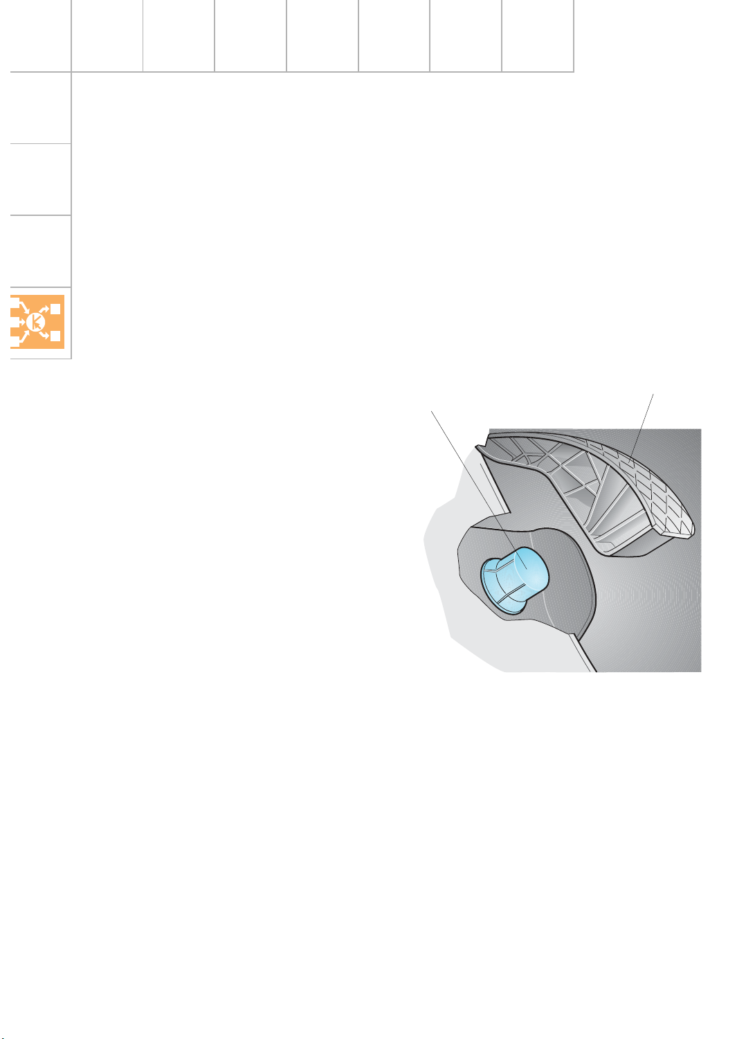
Owing to th e design of t h e va lve re cesses, the
p is ton s a re s p e cifically in te nded for u se in the
a p p ro p riate c ylin d e r bank o n ly.
SSP217_055
SSP217_002
Page 8
8
En g in e - M e c h a n ic s
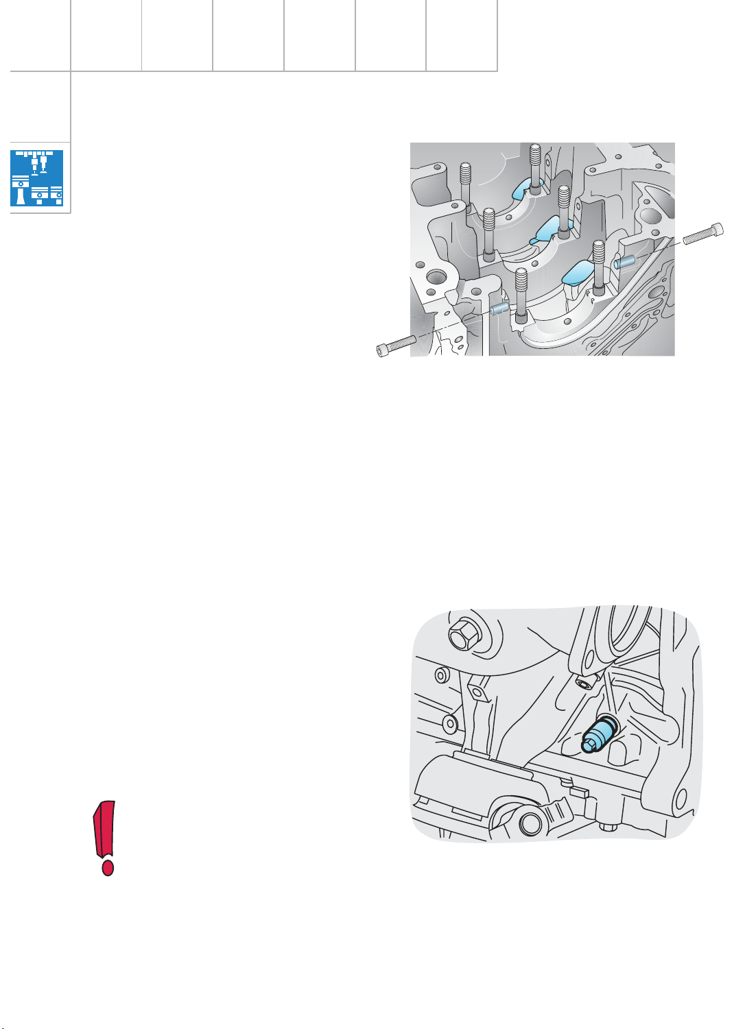
The lockin g m andre l (V.A.G 3242) u s e d fo r th e
V6 e n g in es is a ls o u s e d fo r lockin g th e
cra n ks h a ft. It is a p p lie d to the crank web of
the 4t h cylin d e r a n d is used for b a s ic engine
a d justment an d also as a cou n t erh o ld for
lo osening and tighte n in g t h e c entral b o lt of
the crankshaft.
SSP217_009
The 5th cylin d er m ust b e set t o
ig n ition TDC.
SSP217_007
Wid e , m illed ve n tilation re cess es above th e
thru s t b earin g s reduce pum ping losses.
Bolts are a ls o in s e rte d at t h e s id e o f th e t wo
fron t c ran ksha ft b ea ring caps to impro ve
ru n n in g smooth n e s s
(see SSP 198, page 6).
Page 9
9
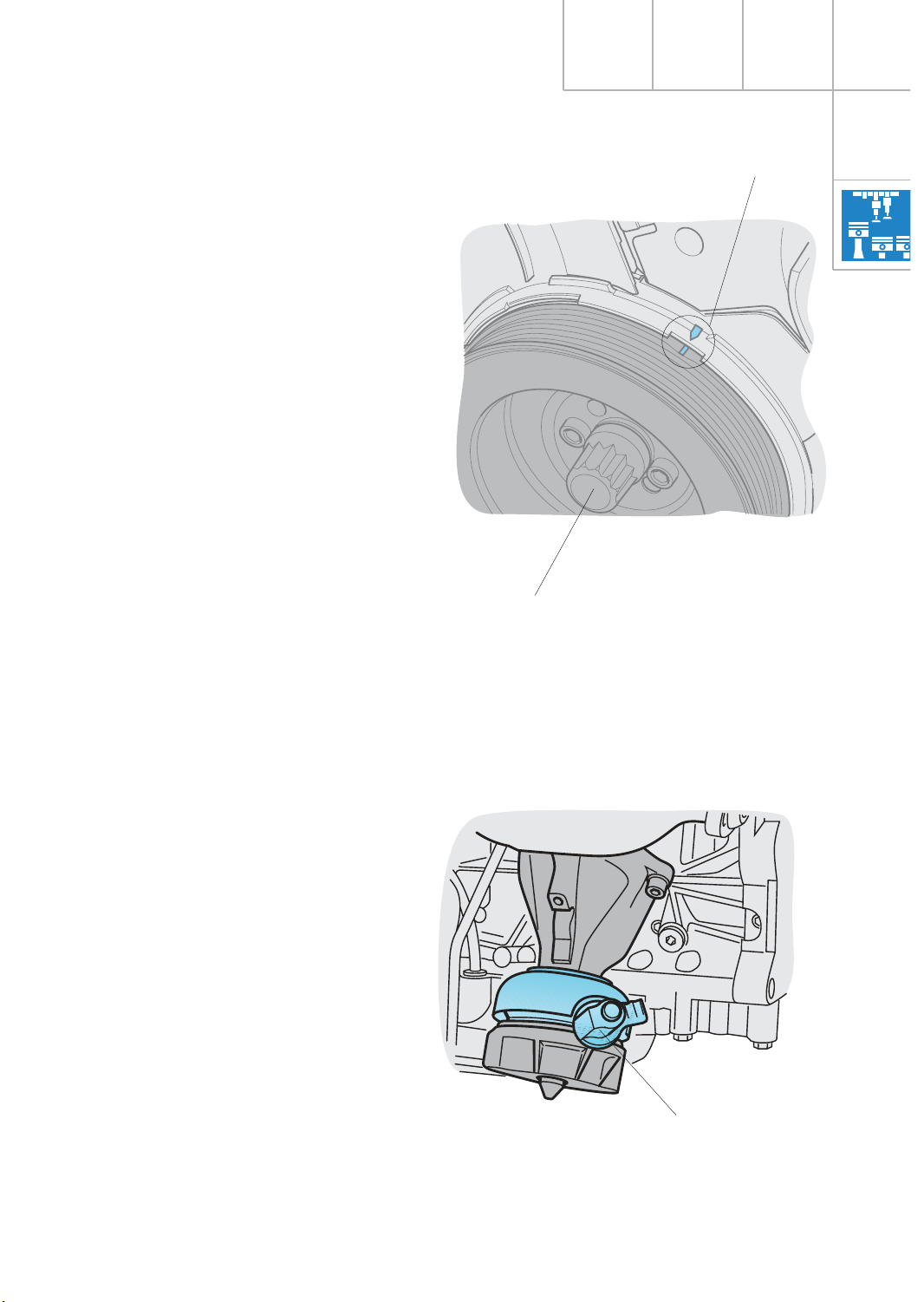
The ce n t ra l bolt d o e s n o t h a ve to be
u nscrewed for t he vib rat io n d a m pe r to be
re m oved.
The m arking indicate s t h e ig n ition TDC of the
5t h c ylin d e r.
SSP217_050
Cent ra l bolt
Ma rking
En g in e m o u n t in g
To e n h a n ce driving co m fort , h ydra ulic engine
m o u n ts with e le c tric a l a ctivatio n a re used for
the 8-cylin d e r en gine s.
They funct io n in t h e w ay as d e s crib e d in
SSP 18 3/16.
The m ounts are a ctiva t e d b y t h e e n g in e
con trol unit accord in g t o e n g in e s p e e d a n d
ve h icle speed.
Elect ric a l c onn ec tion
SSP217_039
Page 10
10
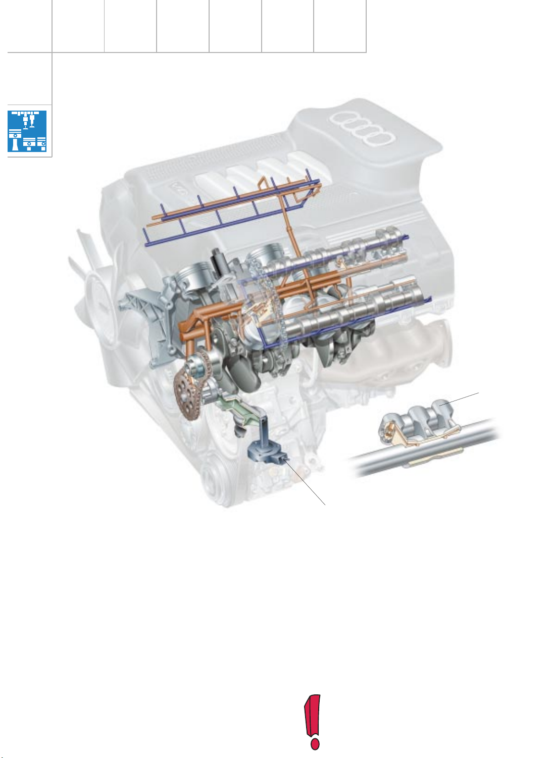
En g in e - M e c h a n ic s
SSP217_010
A d u o centric oil pum p d riven b y the cra n ks h aft via a chain re p la c es the pre vio u s ly u s e d
e xtern a l g e a r oil pum p .
The duoc e n tric o il p u m p exte n d s d ee p into
the oil s um p . The lo w suct io n h e ig h t m e a n s
that t h e o il p ressure c an b u ild u p q u ickly,
e s p ecially with c o ld -star ts.
The oil-pressure c ontr ol va lve is lo cate d in the
oil p u m p ho u s in g . Th e “divert e d “ o il is led o ff
to th e in ta ke s ide of the oil p um p . This h e lp s
optimise the level o f e ffi ciency.
In the inta ke spindle shafts , the re are 5 o il
b ore s p e r tr ip le roller ro cke r. Thre e o il b o res
e ach sup ply one hydra u lic tappet. Two oil
b ore s s up ply the oil-spray b o re s inte g rat e d in
the ro lle r rocker to lubricate th e rollers . Th e
oil-spra y b o res are o n ly o p e n e d w h e n the
ro lle r ro ckers a re act u a ted. This res ult s in a
re d u c tion of the am ount of oil req u ired in the
cylin der h e a d .
Oil-le ve l s e n sor
Trip le ro ller roc ke r
The ro lle r rocke rs a re de sc ribed on
p a ges 20 a n d 21.
En g in e lub ric a t io n
Page 11

11
BA
A
B
B
P
A
A
SSP217_011
Thr ott le
Cylinder bank 1
Oil rete n tion valves
Spray je t valve
Byp ass valves
Oil fi lter m odule
Oil s um p
Oil p ressure co n tro l
va lve
Cam shaft
Cylinder bank 2
Oil fl ow (pre s suris e d )
Oil fl ow (non -p ressuris e d )
Thr ott le
Duoce n tr ic oil pump
Filter element
Oil c ooler
Slight modific a tion s have been m a d e to the
oil circ u it in the cylinder h e a d s .
The oil circuit for cylinder b ank 2 show n in the
illu s tra tion is the oil circuit th a t h a s b e e n
u sed s in ce th e in trod uct ion of the new model.
Cylin d e r ban k 1 show s t h e m o d ified oil
circuit.
Page 12
12
En g in e - M e c h a n ic s
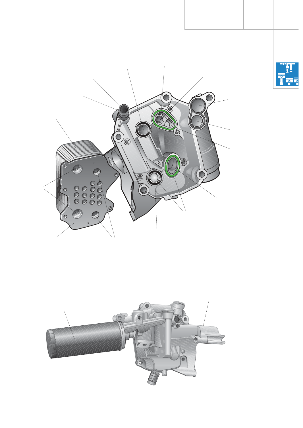
The oil filt e r module co n t ains the oil filte r
a nd o il c ooler. It is also used to ho ld th e
a ltern a tor.
SSP217_013
Oil c ooler byp ass valve
Alte rnat or m ou n t (par t
of o il m od ule )
Coola n t supply
Coola n t
re t urn
Oil s up ply
Oil retu rn
Oil filter module
(A8)
Oil p ressure swit ch
Dra in p lu g
Filter b yp ass
va lve
As was previo usly the cas e , th e o il co o le r is
d e sig n ed as a coolan t-to-oil h e a t e xch an g e r.
The “housing-le s s “ oil coo le r is b olted to t h e
oil filte r m odule using an O-ring seal to form a
s in g le u n it.
Page 13
13
SSP217_014
Oil c ooler
O-ring sea l
Sea ling su rfa ce
(Oil c oole r)
Coola n t supply
(fro m eng ine)
Oil d uc t
Coola n t
re t urn
Oil c ooler byp ass valve
Oil retu rn
(to e n g in e)
Oil s up ply
(fro m eng ine)
Oil c ooler
re t urn
Oil c ooler
s upply
Pla s tic c o nn ect ion
SSP217_003
Oil fi lter car trid g e
Alte rnat or
h older
For s p a ce re asons, the A6 o il filter m o d u le is
fitt ed with an oil filte r ca r trid g e .
Oil filter module
(A8)
Oil filter module
(A6)
Engine oil
Coola n t
Coola n t supply
Page 14

14
En g in e - M e c h a n ic s
The pitc h o f t h e in tern a l g ea r and the
e xtern a l runner h as n o fu n ction al
s ig n ifica n ce a nd is d e t erm ined by
p ro d u ction enginee rin g fa cto rs.
To e n s u re th a t the assembly
fu n ctio n s co rrect ly, the n arrow g e a rs
m u s t n ot ru n t ogeth e r on the same
p la n e.
SSP217_012
External ru n n er
Inte rn al gea r
Oil p ressure co n tro l va lve
Duocentric oil pump
Oil level sensor
The oil level s e n s or fun ctions as an in fo rm ation sender which a llo w s t he flexible servic e
in terva l to b e calcu late d and the oil le ve l to b e
d is p la ye d in th e d a s h p a n e l in s e r t.
Furt h e r in for m a tion can be found in SSP 207
(fro m page 84 o n ward s ) a n d SSP 213 (fro m
p a ge 55 o n ward s ).
SSP217_063
Oil le vel sen so r
Page 15

15
N o t e s
Page 16

16
En g in e - M e c h a n ic s
The flo w d ire c tion of the coo la n t h as b e en
cha n g e d in th e new V8 5-valve engines.
As with t h e V6 e n g in e s , t h e coolan t le a vin g
the cylinder h e ads m e rges in the re a r co o lant
p ip e from where it is t h e n le d o ff to th e
coo le r.
SSP217_015
Co o lin g c irc u it
(Exam p le : A8)
Retu rn fro m oil
coo le r
Heat e xch a nger / va lve
u nit
Coola n t tem per atu re
s ender G2 a nd G62
Radiato r fa n t herm o
s witch F18/F54
Coola n t pipe
(re tur n fo r h e a ter, oil
coo le r a nd expan sion
tan k)
Bre a the r pipe
Ne w coo la n t pipe to
cylinder head
(sm all coo lin g circ uit)
Page 17

17
Oil c ooler re turn
The new c o olant pipe alter s the coo la n t flow
in t he „s m a ll“ co o lin g c ircu it .
SSP217_016
Coola n t pipe
(re tur n fo r h e a ter, oil co o ler
a nd expans ion ta n k)
Ne w coo la n t pipe to
cylinder head
(sm all coo lin g circ uit)
To e xpa ns ion t a nk (A8)
Coola n t re turn
Heat e xch a nger (A6)
Bre a the r pipe
(to e xpa ns ion ta n k)
Coola n t supply
fo r h e a t exch anger
to veh icle radia to r
Coola n t re turn
Heat e xch a nger (A8)
to expa n s io n tan k (A6)
Coola n t tem per atu re
s ender G2 a nd G62
Coola n t pipe (re ar)
Page 18

18
Previous design:
The co o la n t ther m o s tat is co n n e cted to t h e
“sm a ll c oolant circu it “ via tw o h o le s in t h e
cylin der c ra n kc a se (see Fig. 217_017).
The holes are d irect ly connect ed to th e
cylin der-h ead wate r jacke t (1st c ylin d e r) and
the wa ter ja cket o f the cylinder c ra nkcas e. The
h eate d co o la n t flo w s from the 1s t c ylin d e r to
the co o la n t therm o s tat.
SSP217_018
En g in e - M e c h a n ic s
New design - m odified components:
– Cylin d e r head in b a n k 1 m o d ified
– Additio n a l c o olant pipe
– Re a r c o olant pipe m o d ified
The co n n e ctio n in th e cylin der head to th e
wate r jacke t (cylin d er c ra n kc a s e) has been
s p lit (see Fig. 217_019).
The co o la n t from the re a r c o olant pipe is
fo rked by the new co o la n t pipe (m ixture fr om
a ll cylin d e rs) and the n pas s e s t h ro u g h t h e
cylin der h e a d t o the tw o h o le s w h ich lead off
to th e c o olant th e rm ostat .
This ensure s u n ifo rm tempera ture c ontr ol.
The funct io n o f t h e c ylin d e r hea d is to
con nec t the co o la n t p ip e to the tw o h o le s
le adin g o ff to t he coola n t t herm os ta t.
SSP217_019
SSP217_017
Ne w coo la n t pipe
Ne w d esign
Fro m radiat or
To c oola nt p u m p
Coola n t the rm ost a t
Coola n t pipe
(re tur n fo r h e a ter, oil co o ler
a nd expans ion ta n k)
Page 19

19
The ro ckers a re m ade of d ie -c ast alum inium
in o rder to keep in ertia fo rce s as low a s
p ossible. As a re s u lt , t h e va lve g e a r is able to
fu n ctio n re lia b ly a t e n g in e s p e e d s o f u p to
72 00 rpm .
The use of ro lle r ro ckers h a s n o t only m ea nt a
con sider able re d u c tion in frict io n al lo s s e s in
the valve gear, b u t has also halved the oil
d e live ry ra te in t he cylin der h e a d s . This a ls o
h as a p ositive effe ct on th e d e g ree of
e fficie n cy.
Five -valve tech n o lo g y is now a ls o b e in g u s e d
in t he V8 engines.
Roller rocke rs a re being used for t h e firs t tim e
in t he e n hance d five -va lve c ylin d e r head.
This co n s id e rably re d u ces frict ional lo s ses in
the valve gear w hich , in turn , significantly
im p roves effic ie n cy.
SSP217_020
Cy lind e r he a d
Five-valve technology
Page 20

20
SSP217_023
En g in e - M e c h a n ic s
Roller rocker
Exhaust valve
Eve ry valve h as a h yd rau lic va lve lifter which
is in t egra ted in t h e ro cke r. The ro ckers a re
s upport e d b y a spindle shaft wh ic h is a ls o
u sed to supply oil to th e bea rings a n d the
h yd rau lic va lve lifters .
The tw o e xhau st valves are a ct uate d by a t win
ro lle r ro cker.
The single cam a ctu a tes the ro cker b y m ean s
of a roller lo cate d betw een the ro cker a rms.
SSP217_022
Spind le sha ft,
a lso use d to
s upply oil
Exhaus t va lve
20 .2˚
Roller lo cat e d b etw e en
ro cker a rm s
Twin
ro lle r rocke r
Single ca m
Oil s pr ay hole
The individual h yd ra ulic va lve lifters
can be re p la c ed witho u t the ro ckers
n e eding to be re m oved .
Page 21

21
Inlet valve
Tolerance compensation for inlet
triple RR (roller rocker)
To e n s u re uniform co m p ression
b e twe e n t h e two ca m s and ro lle rs
of t h e ro lle r ro ckers , th e s p in dle
s h aft of the in le t ro lle r ro cker is
con vex in s h a p e in o rder to
com pensate a lig nm ent and
com ponent t o le ra n c es. This
p re ve n t s t h e ro lle r ro ckers fro m
“tilting“.
SSP217_024
Double ca m
Hyd ra u lic va lve lift er
with s lide pad (hydraulic
va lve tapp et )
Oil d uc t
Spind le sha ft
Inlet va lve 2
14 .9˚
Inlet va lve 1 a n d 3
21 .6
o
SSP217_021
Cylin d er h e ad
The th ree inlet valves a re ac tuate d via a trip le
ro lle r ro cker.
A d o u b le cam a ctua t e s the ro cker b y means
of t wo ro lle rs betw e e n t he ro cker a rm s .
SSP217_025
Trip le ro lle r roc ke r
Cam s
Rollers
Spind le sha ft
a xis (ta rge t)
Spind le sha ft
a xis (act ual)
Ca m s haft axis
For the sake of c larit y, the
tolerance of the spin d le s h a ft
re la t ive t o the ca mshaft has
b e en g re a t ly e xa g g e ra t e d in
the illustr ation .
Page 22

22
En g in e - M e c h a n ic s
Camshaft adjust er
(cylinder b a n k 1 )
In the ca s e o f th e n e w V8 engines, a n
in terlo ck fu n ctio n a nd an oil re s e rvoir w e re
a d ded to th e p roven s ys t em d u ring the
cou r se of fur ther d e ve lo p m e n t.
Thes e new fea t u re s preve n t vib ra t ions in t h e
cha in drive w h ich has a p ositive effect o n
a cou s t ic b ehaviour d u ring th e s ta rt phas e .
The ca m shaft a d ju s t m e n t s ys t em , a featu re
in corp ora t ed in Audi's curre n t range of
e n gin es, is also used in the n ew genera tion o f
V8-5V en gines .
Wh e n the engine is s w itch e d o ff, n o oil
p re ssure is a pplied to the ch ain tension er a n d
camshaft adjuste r.
Owing to th e Fe rra ria effect in t h e chain d rive
when th e en gine is s tarted, vib ratio n s w h ich
g e nera te n oise occ u r un til s ufficient oil
p re s s u re has built up.
SSP217_026
Chain te n s ioner s lid e pad
Lockin g pins for
s tar ting phas e
Slide pad adju st e r
Cam shaft a d ju s tm ent
va lve N2 05
Hyd ra u lic cylinder with
s witching pisto n
The prin ciple o f c a m s h a ft
a d justment is describ ed in S SP 182.
Oil reser voir
Te n s ioning pisto n
Adjus te r pis to n
Page 23

23
BBA
A
BBA
A
B
A
BA
SSP217_027
Engine off:
If there is no oil p re s sure ,
a s p ring-loa d e d loc kin g
p in is p us he d into t h e
d e tent s lo t o f th e
a d justing pisto n . Th e
a d justing pisto n is th e n
lo cked.
Oil retu rn
Oil s up ply
Oil reser voir
Lockin g pin
Adjus tin g p is ton
SSP217_029
SSP217_028
The ca m s h aft adjuste r is locke d in th e
“Re tard p o s ition“.
Engine running:
On ce a d efi ne d o il p re ssure h as b een re ach ed,
it acts o n t h e s u rface o f th e loc kin g p in , i.e .
a gainst th e r esistan ce o f th e s p ring.
The lockin g p in re le ases the adjustin g pisto n
s o that t h e e n g in e c ontrol u n it can adjust th e
tim in g in t h e “Ad va n ce“ d ire c tion.
Cont ro l d uc ts
Lubricatio n a n d
b re a the r h ole
Engine start:
The adjust in g p is to n is lo cke d u n til s u fficie n t
oil p ress ure h as b uilt up. This pre ve n ts
vib rat io n s in th e chain d rive and, there fo re ,
n oise g e n era tion.
Oil reservoir
The oil re s e rvoir e n s ure s t h a t the pre s s ure
cha m ber o f t h e tensioner p is ton is filled
d urin g th e n on -p ressur is e d p h ase of t he
s tart in g cycle.
This also has a positive effect o n a c oustic
b e haviour w hen the engine is s tart e d .
A h o le in t h e top of t he oil rese rvo ir allow s a ir
to esca p e a n d s up plies th e c h a in with oil.
Retard set ting
(Bas ic a n d p o w er s e t ting)
Advance setting
(To rq u e s e t ting)
Page 24

24
En g in e - M e c h a n ic s
Toothed-belt drive
The to o thed-b e lt drive is id entica l to that of
the V6-5V e n g in e . The V8-5V e n g in e is a ls o
fitt ed with a stab ilising ro lle r.
The co mponent s are la rgely id e n tical to th ose
of t h e V6-5V e n g in e .
Cylinder-head seal
The new V8-5 V e n g in e s h a ve a multi-la ye r
m e tallic cylinder-head seal alre a d y u s e d in
the 4 an d 6-cylin d er e n g in e s . Th is s e a l
re p la c e s the soft seal used in p reviou s
m o d e ls .
SSP217_038
Sta b ilis in g ro lle r
It co n s is ts of 3 in d ivid u a l m et a llic la ye rs.
The tw o o u term o s t la ye rs are t re a t ed with a
s p e cial co a t in g .
Advantages:
– Ve ry good settlin g b e h a vio ur
– Im p rove d durability
SSP217_056
Coat in g
Ecc e n tr ic ro lle r
Page 25

25
The above-m entio n e d m eas u res m e ans that
the cylinder h e ad cover is not dire ctly co up led
with the cylinder h e a d . It is , t h e re for e, “in sulated“ against vibra tions g enera ted b y the
e n gin e.
SSP217_040
Cylin d e r h e a d
c ov er
De co u p lin g e lem ent
(shor t)
SSP217_043
The secu ring bolts m u s t b e tighte ned
u niform ly in t he s p e cifie d o rder to
p re ve n t d is t ort io n o f t h e c ylin d e r
h ead cover a n d to ensure that th e
s e al is c om p le tely air-tight.
Alwa ys re fe r to t he in fo rm atio n g iven
in t he re p a ir m a n ual.
Cylinder-head cover seal
The th in -w all cylin d e r h ea d co ve rs are m ad e
of a die-ca st magnesium a lloy. A seal con ce pt,
which deco uples the cylinder h ead cover from
the cylinder h e ad, im pro ve s the acou s t ics of
the engine.
The bolte d c o nnect io n s o f th e c ylin d e r hea d
cover h ave d e coup ling elem e n ts.
A s e a l, w h ich is s im ilar to a ra d ia l s h a ft o il
s e al, is us e d for the spark-p lu g s h a ft .
735
119
1012
648
1
2
Spac er s le e ve
Sea l cylinder head co ve r
De cou p lin g
e lem ent (lo n g )
Sea l
Pro filed ru b ber g ro m met
Spac er s le e ve
Page 26
26
En g in e - M e c h a n ic s
This pro tect s the in d ivid u a l c ylin d e rs
e ffe ctively against a n n o ying exhaust
vib rat io n s w h ich , in turn , has a positive
e ffe ct on engine-to rq u e c hara cte ristics .
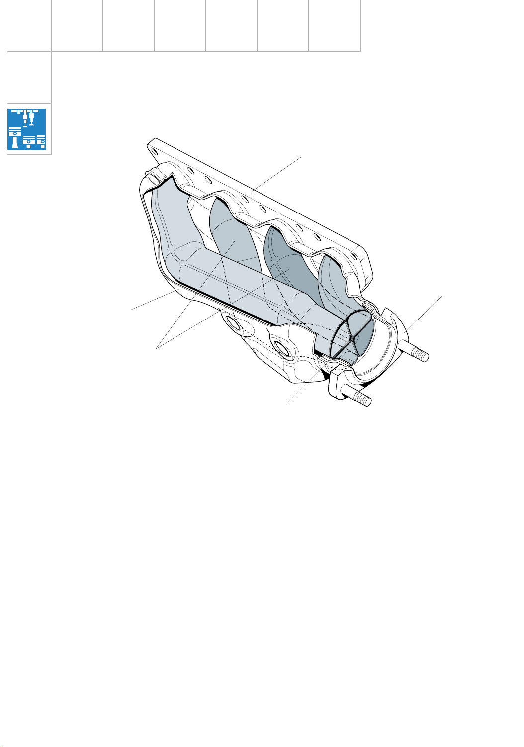
The pipe sect io n s a n d a s s e m b ly o f th e airg ap-insulate d exhau s t m an ifold have been
m o d ified.
The exhaus t p ipes of the individ u al cylin d e rs
a re a s s e m b le d in a cloverle a f c onfig u ratio n
fo r e a ch cylinder b a n k (4 in 1 a rrangem ent).
Exhaust manifold
SSP217_036
Ma n ifo ld flan ge
(left-h an d c yl. b an k)
Conn ec tion for fron t
e xh aus t p ipe
Cloverle a f
a rran ge m en t
Individua l p ipes
res ha p e d fo r
in ter nal high
p re s s ure
Ou ter shell
Page 27

27
Increas ing to rque b y m ean s of va riable intake
m a n ifo ld s is a tradition at Audi. A thre e -s tage
va riab le inta ke m anifold m a d e o f a die-ca s t
m a g n e s iu m a llo y, a furt h e r d e ve lo p m ent o f
p re vio u s c o n cepts , is to be used for t he firs t
tim e .
The varia b le in t a ke m an ifold co n s is t s o f fou r
p rincip a l h o u s in g c om p o n ents wh ic h a re
b onded and b o lted to g e ther.
The co nce pt u ses two intake m a n ifo ld flaps to
p ro d u ce thre e d iffe rent inta ke m anifold
le n g ths (“re s o nance tu b e le n g t h s “). To u t ilis e
the pulsatio n s t o o p tim um e ffe c t, the in take
m a n ifo ld fl aps close th e resonance t u b e
openings b y m ea n s of a circum fe re n t ia l,
m o u ld e d -on s ealing lip .
SSP217_030
Holders fo r
in je cto rs
The varia ble in take m an ifo ld m us t not
b e d is m a n t le d . If n ec e s s a ry, t h e
e n tire a s s em b ly m ust b e co m plet e ly
re p la c e d.
Va ria b le int a k e m a n if o ld
Intake module
SSP217_031
Inta ke m an ifold fla p , s ta g e 3
F
r
o
m E
-th
r
o
t
t
l
e
v
a
l
v
e
s
y
s
t
e m
Inta ke a ir (inle t)
Inta ke m an ifold fla p ,
s tag e 2 (ope n)
Reson an ce tube, cyl. 5
(inlet s ide)
Va cuu m unit
Inta ke m an ifold fla p ,
s tag e 2
Va cuu m unit
Inta ke m an ifold fla p , s ta g e 3
En g in e - M o t ro n ic Su b sy st e m s
Page 28
28
En g in e - M o t ro n ic Su b sy st e m s
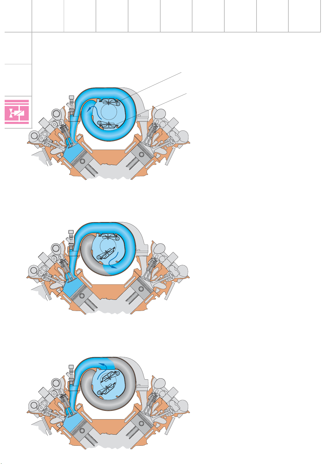
Stage 1
Lower speed range
Stage 2
Middle speed range
Stage 3
Upper speed range
In the upper s p eed ra n g e , th e s t a g e 3
in take m a n ifo ld flap is a ls o o p e n e d . The
in take air t a ke s t he s h ort e s t p ath to t h e
com bustio n c h am b e r.
Wh e n the engine is s w itch e d o ff, b oth
flap s are o p e n .
If the engine is id lin g , th e t w o va cuum
u nits are e va c uate d by th e appropria t e
in take m a n ifo ld changeover s olenoid
va lve s . The in take m a n ifo ld fl aps a re ,
there fore , clo s e d b e t ween th e idling
s p e ed a n d the s witching s p e e d.
SSP217_033
SSP217_034
SSP217_032
Inta ke m an ifold fla p
Sta g e 3
Inta ke m an ifold fla p
Sta g e 2
In the mid d le s p e e d ran ge, the inta ke
m a n ifo ld c hangeover s o lenoid va lve
N1 56 a llo ws atmospher ic p re s s u re into
the vacu u m unit of the sta g e 3 in take
m a n ifo ld fl ap.
The sta g e 2 in take m a n ifo ld fl ap is
opened and the intake path is s h ort e n e d .
Page 29
29
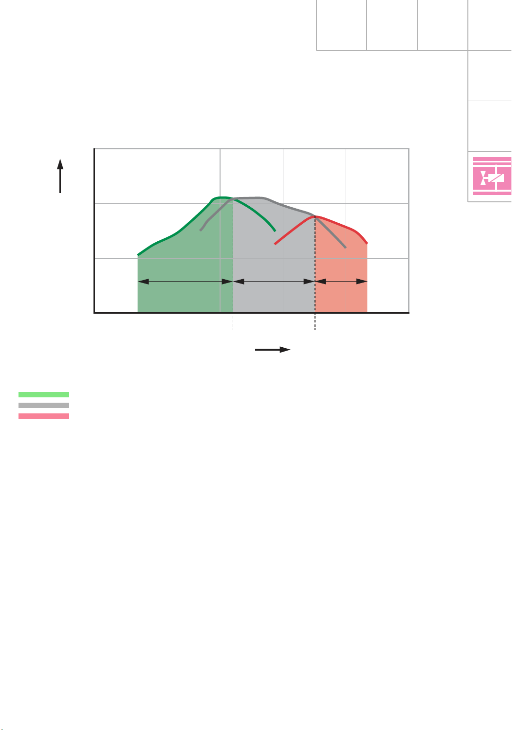
Effect of variable intake manifold on torque
The illustratio n explains th e co rrelatio n
b e twe e n t h e le n g th/cro ss s e ctio n o f th e
in take m a n ifo ld a n d e ngine speed and shows
the ch a racteris t ic torque cu rve p rod u c ed b y
the 3 st a g e s .
SSP217_035
Lowe r fu ll t hro tt le (s tag e 1)
Mid d le fu ll th ro ttle (st a ge 2)
Up p e r fu ll th rott le (sta g e 3)
Since t h e m aximum torq ue a cross the speed
ra n g e d ep en d s prim a rily o n the le n g th and
cro s s s e ctio n o f th e inta ke m anifold, the new
thre e -sta g e varia b le in t ake m a n ifo ld co m e s
closes t t o p rod u c in g the optimum characte ris tic to rqu e c u rve across th e spee d ra n g e.
De p ending o n the engine s p eed, a p p rop r iate
“res onance tu be le n gths“ are available for t h e
lo wer, m id d le a n d u p p e r speed ra n g e .
200
500
400
300
0 1500 3000
3360 5200
4500 6000 7500
Spee d
To rqu e
Page 30
30
En g in e - M o t ro n ic Su b sy st e m s
SSP217_051
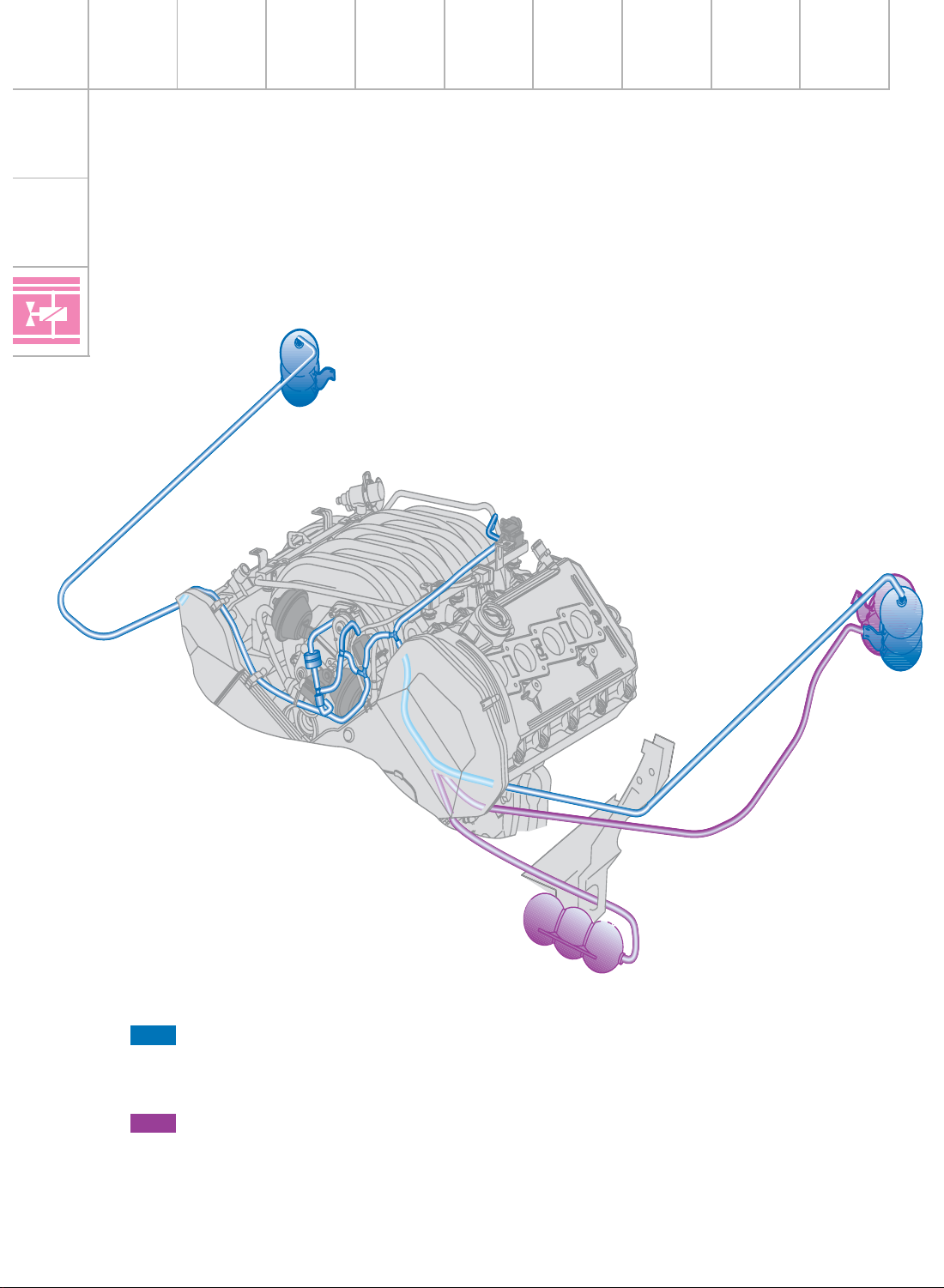
The vacu u m re quire d t o control th e varia b le
in take m a n ifo ld a n d t h e s e condary a ir system
is p rovided by two vacu u m reservo irs. If a
va cuum e xis ts in t he in take m a n ifo ld , th e
re s e rvoirs a re evacua t e d via a non -re t u rn
va lve .
Fittin g lo cat io n of va cuum re s e rvo ir,
Aud i A8
Fittin g lo cat io n of va cuum re s e rvo ir,
Aud i A6
Page 31
31
SSP217_052
Inta ke m an ifold ch a n geover
s oleno id va lve N261, sta g e 2
No n -re turn va lve
Va cuu m unit,
s tag e 2
Inta ke m an ifold ch a n geover
s oleno id va lve N156, sta g e 2
Fro m vac uum re s e rvo ir
Fro m vac uum
re s e rvoir
Va cuu m unit,
s tag e 3
Sec o ndar y a ir in let
va lve N1 12
Page 32

32
En g in e - M o t ro n ic Su b sy st e m s
Se c o n d a ry a ir sy ste m
Owing to th e high m ixture e n rich m ent d ur in g
the co ld -s t art a n d w a rm-up phase, an
in cre ased p ro p o rtio n o f unburn t h yd ro c a rb ons e xis ts in t he e xh a ust gas durin g t h is
tim e .
The ca t a lytic co n ve r ter cannot p roce s s t h is
h ig h p rop o r tion of h yd roc a rbon s beca u s e :
1. the re q u ired oper ating te m pera ture o f t h e
cata lyt ic convert er h a s n o t ye t b e en
re a ched and
2. a la m bda 1 m ixtu re m u s t e xis t to allow
com plete co n ve rsion.
Air in je ction down s t re a m of the outle t va lve s
causes oxygen enrichm e n t of the e xh a ust
g ases. As a re s u lt, t he h yd roc a rbon s an d th e
carb o n m on o xid e u n d e rgo post-o xid a tion
(after b urn in g ). Th e therm al energ y releas e d
d urin g this p ro ce ss also heats up the cat alytic
con vert er s o t h a t it re a ches its oper ating
tempera ture m ore quickly.
The seco n d a ry air s ys t em c onsists of
– t he s econ d a ry a ir p um p V101
– t wo co m binatio n va lve s A + B
– t he s econ d a ry a ir inlet va lve N112
J220
N112
G108
J299
V101
G39
G70
G62
SSP217_042
Energ is ed
No t energised
A
B
Page 33

33
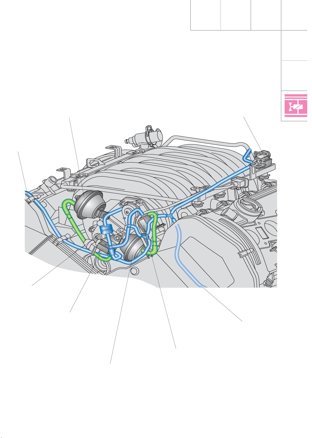
SSP217_001
Sec o ndar y a ir in let va lve N112
Combina tio n va lve
Cylin d er b a n k 1
Conn ec tion for fres h air from
s eco n d ary a ir pum p V101
Combina tio n va lve
Cylin d er b a n k 2
Va cuu m fro m eng ine
Cont ro l line (vac u um o r a tm osph er ic
p re ssu re from seco n dary a ir in let valve
N1 12)
Fre sh air from s eco nd ary a ir p ump
V1 01
Page 34

34
En g in e - M o t ro n ic Su b sy st e m s
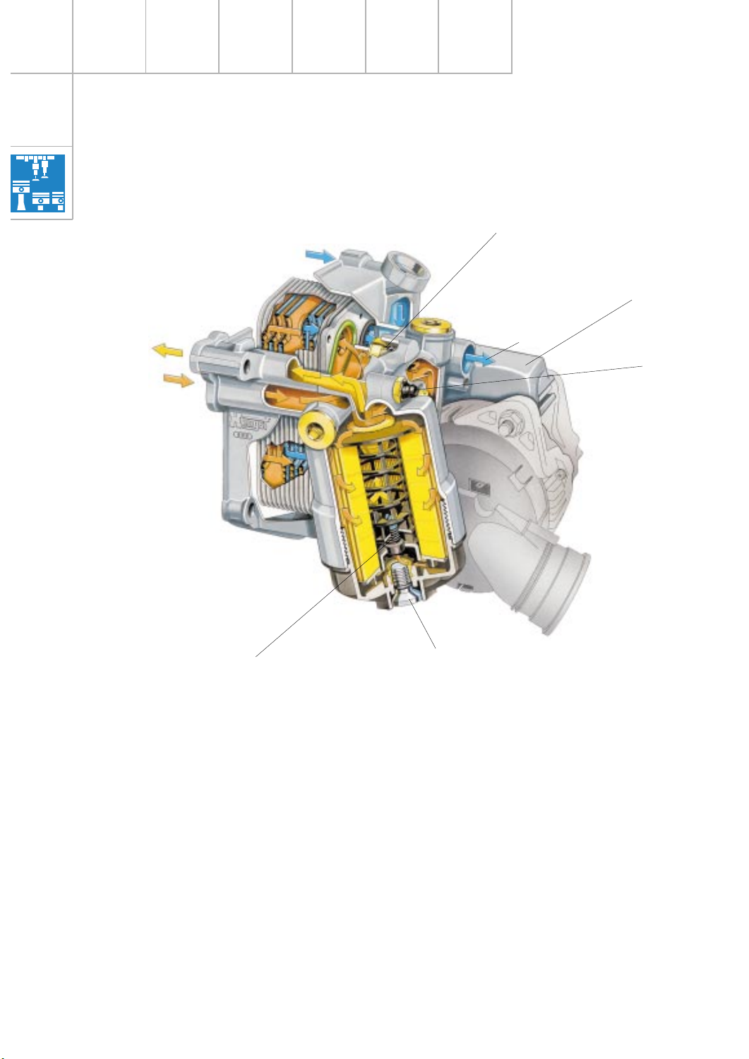
Combinat ion valve
The co m b in at io n va lve is bolte d to t he
s e con d a ry a ir d uc t of t h e cylin d er h e a d .
The vacu u m fro m th e s e c ondary a ir inlet
va lve c a uses the air channel betw e e n the
s e con d a ry a ir p um p and the seco n d a ry duct
of t h e cylin d e r h e a d t o o p en.
At th e s a m e tim e, the va lve p revents ho t
e xh a ust gas es fro m en te ring and then
d a m a g in g t h e s e con da r y a ir pum p.
Secondary air inlet valve N112
The seco n d a ry air in le t va lve is an elect ro p n e um a tic valve. It is act iva t ed b y t h e Mo t ro n ic con trol unit and co n t ro ls t h e com b in a tion
va lve .
It releases th e vacu u m s to re d in th e re s e rvoir
to open th e co m b in a t ion va lve .
Atm ospheric p re ssure is releas ed to clo s e t h e
com binatio n valve.
SSP207_016
Valve open
Fre s h a ir from
s e con d a ry air
p um p
To s e con da ry
a ir d u ct
Valve closed
Atm os phe ric
p re s s ure in c ontrol
lin e from s eco n d ary
a ir in let va lve
Exhaus t g a s
SSP207_019
SSP207_018
Va cuu m in
con tro l line fro m
s eco n d ary a ir inlet
va lve
Filter cap
Atm os phe re
To va c uum re se rvo ir
Energ is ed
No t energised
To c ombinat io n
va lve s
Page 35

35
The seco n d a ry air s ys t em is
d e scrib e d in S SP 2 07 .
SSP217_049
Air filte r box
Sec o ndar y a ir p um p,
Aud i A8
To c ombinat io n va lve
Secondary air pum p V101
The seco n d a ry air p u m p relay J 299 act iva ted
b y t he Mo tro n ic control unit co n n e cts th e
p ower s upply fo r th e s e c ondary a ir pum p
m o tor V101. The fre s h a ir m ixe d with th e
e xh a ust gas is d ra w n from the air fi lter
h ousing b y the s eco n d a ry air p u m p and
re le a s e d b y t h e com b in a tion valve.
The seco n d a ry air p u m p in the Au d i A8 has its
own air filte r.
The pump is in t e g ra t ed in t h e a ir filter
h ousing wher e it d ra w s in u n fi ltere d a ir.
The seco n d a ry air s ys t em is ac tive a t coo la n t
tempera ture s b e tween 0 a n d 55 ˚C.
The seco n d a ry air p u m p relay J 299 and the
s e con d a ry a ir inlet va lve N112 are a c tivate d
s im u lt aneous ly.
The syste m is s witch e d o ff afte r a d efin e d air
m a s s h as b e e n d raw n in by the m oto r
(inform atio n from t h e a ir m ass m e ter).
At idling speed, this occu rs after
a p p ro x. 60 - 90 s e conds.
The seco n d a ry air p u m p in th e Audi A6 d o e s
n ot have its own air filte r. It is m ounte d to t h e
lo ngitudinal m e m b e r an d dra ws the filt e re d
a ir fro m t h e a ir filt er b o x.
SSP217_057
Air filte r box
Sec o ndar y a ir p um p
Aud i A6
To c ombinat io n
va lve
Clean air in take
Page 36

36
Sy st e m o v e rv ie w
Motronic M E 7.1
Sensors
En g in e M a n a g e m e n t
Altit u de send er F96
(inte g ra te d in c ontrol un it)
Hot-film a ir m ass m ete r G70
Engine spe ed sen de r G28
Hall s e nder G40 (bank 2) a n d
Hall s e nder 2 G163 (b ank 1)
La m b da pro be G39 (bank 1) a n d
la m b d a pro b e G10 8 (b a n k 2)
Coola n t tem per atu re se nd er G2 an d G62
Kn ock s e nsor 1 G6 1 (b ank 1) a nd
kn ock se ns or 2 G6 6 (b ank 2)
Bra ke lig h t swit ch F and
b ra ke p e d al s witch F47
Clutc h p edal swit ch F3
(wit h m an ua l g ea rbox on ly)
Additio n al s ignals
– Air c onditio n e r req uirement s ig n a l
– Air c onditio n e r c ompre ssor,
b id ire ctio n a l
– Cra s h s ig n al
– CCS swit ch
Thr ott le va lve con trol un it J 338 with
thr ott le va lve d rive G186 (e le ct ric
thr ott le operatio n )
Angle se nd er -1- fo r th rot tle valve drive G1 87
Angle se nd er -2- fo r th rot tle valve drive G1 88
Pe dal send er /a cce le ra tor peda l m odule wit h
a cc e lera tor ped al pos itio n s e nder (1) G79
a nd
a cc e lera tor ped al pos itio n s e nder (2) G185
Mo tro nic
con tro l unit J 220
Cont ro l u nit fo r
ABS w ith EDL J 104
Aut om atic g e arb o x
con tro l unit J 217
* Com binatio n p ro cess or
in d ash pan el inse rt
J 218
* Air c onditio n er/Clim atron ic
operatin g an d displa y unit
E87
Ste e rin g an gle
s e n der G85
* No CAN b u s inte rfa ce
with Au di A6
Page 37

37
Active components
Fuel pum p re la y J 17 a n d
fu e l p u m p G6
Injec tor s N30, N31 , N32, N33
(bank 1)
Injec tor s N83, N84 , N85, N86
(bank 2)
Ignit io n coil N (1st c yl.), N 128 (2nd cyl.),
N1 58 (3rd cyl.), N1 63 (4t h cyl.)
Ignit io n coil N164 (5t h cyl.), N189 (6th c yl.),
N1 90 (7t h cyl.), N1 91 (8t h cyl.)
Act iva ted ch a rc oal filt er s ys tem s oleno id va lve N80
Sec o ndar y a ir p um p re la y J 29 9 an d
s eco n d ary a ir pum p m o to r V101
Sec o ndar y a ir in let va lve N112
Cam shaft a d ju s tm ent valve
N2 05 (bank 1) a n d N2 08 (bank 2)
Inta ke m an ifold ch a n geover
va lve N1 56
Inta ke m an ifold ch a n geover
va lve 2 N261
La m b da pro be heat in g Z19 (b ank 1) a nd
la m b d a pro b e heat in g Z28 (b a nk 2)
Thr ott le va lve con trol un it J 338
with t h ro ttle va lve drive G186
SSP217_046
Additio n al s ignals
– Air c onditio n e r c ompre ssor (ou t)
Diagnos is
Engine moun t 1 a nd 2
Page 38

38
En g in e M a n a g e m e n t
Fu n c t io n d ia g ra m
4.2/ 3.7 l in A8 GP
Colour coding
= Po s itive
= Ea rth
= In put s ign al
= Ou t put s ign al
Component s
A Batt ery
E45 Cru is e con trol syste m
s witch
D Ignit io n /s tar ter swit ch
F Brake lig ht sw itch
F36 * Clutc h p edal swit ch
(wit h m an ua l g ea rbox on ly)
F47 Brake ped al sw itch fo r cruise co n trol
s ys tem
G2 Coola n t tem per atu re se nd er
G3 Coola n t tem per atu re ga ug e
G6 Fuel pum p
G28 Engine spe ed sen de r
G39 La m b da pro be
G40 Hall s e nder
G61 Kn ock s e nsor 1
G62 Coola n t tem per atu re se nd er
G66 Kn ock s e nsor 2
G70 Air m as s m et e r
G79 Acc elera to r pos it ion send er
G10 8 La m b da pro be 2
G16 3 Hall s e nder 2
G18 5 Acc elera to r pos it ion send er 2
G18 6 Thr ott le va lve d rive
(electric thrott le o peratio n )
G18 7 Angle se nd er 1 for th rott le va lve d rive
G18 8 Angle se nd er 2 for th rott le va lve d rive
J 17 Fuel pum p re la y
J 220 Mo t ro n ic co n trol u nit
J 299 Seco n dary a ir pum p re la y
M9 Bra ke lig h t bulb (le ft)
M10 Bra ke lig h t bulb (rig h t)
N Ignit io n coil (cylin de r 1)
N3 0 Injec tor (cylin der 1)
N3 1 Injec tor (cylin der 2)
N3 2 Injec tor (cylin der 3)
N3 3 Injec tor (cylin der 4)
N8 0 Act iva ted ch a rc oal filt er s ys tem s oleno id
va lve
N8 3 Injec tor (cylin der 5)
N8 4 Injec tor (cylin der 6)
N8 5 Injec tor (cylin der 7)
N8 6 Injec tor (cylin der 8)
N1 12 Sec o ndar y a ir in let va lve
N1 28 Ignit io n coil 2
= Bid ire ctiona l
Additional signals and connect ions
K dia gn os is co n nect ion
1 Cra sh signal (in ) from airb a g con trol un it
2 Air con ditio n er req u ire men t s ign al (in)
3 Air con ditio n er compressor signal (in -out )
CAN-BUS L } Co nnection to d a ta bu s
CAN-BUS H }
X}
Y } Conne ctions in fu n ct io n
Z } d iagra m
N1 44 Sole no id va lve (left) fo r ele ctro /h yd ra u lic
e ngine moun t ing
N1 45 Sole no id va lve (rig ht) for elec tro /h yd ra u lic
e ngine moun t ing
N1 56 Inta ke m an ifold ch a n geover valve
N1 58 Ignit io n coil 3
N1 63 Ignit io n coil 4
N1 64 Ignit io n coil 5
N1 89 Ignit io n coil 6
N1 90 Ignit io n coil 7
N1 91 Ignit io n coil 8
N2 05 Cam shaft a d ju s tm ent valve 1
N2 08 Cam shaft a d ju s tm ent valve 2
N2 61 Inta ke m an ifold ch a n geover valve 2
P Sp a rk plug co n n ect or
Q Spark p lu gs
S Fus e
ST Fu s e h older
V1 01 Sec ondar y a ir p um p m oto r
Z19 La m bd a probe hea t ing
Z28 La m bd a probe hea t ing 2
S204 Fittin g loc a tion in Audi A6: plen um cha mber
n e xt to b a tte ry
Fittin g lo cat io n in Aud i A8 : top rig h t
in lu ggag e co m p a rt m e n t
Page 39
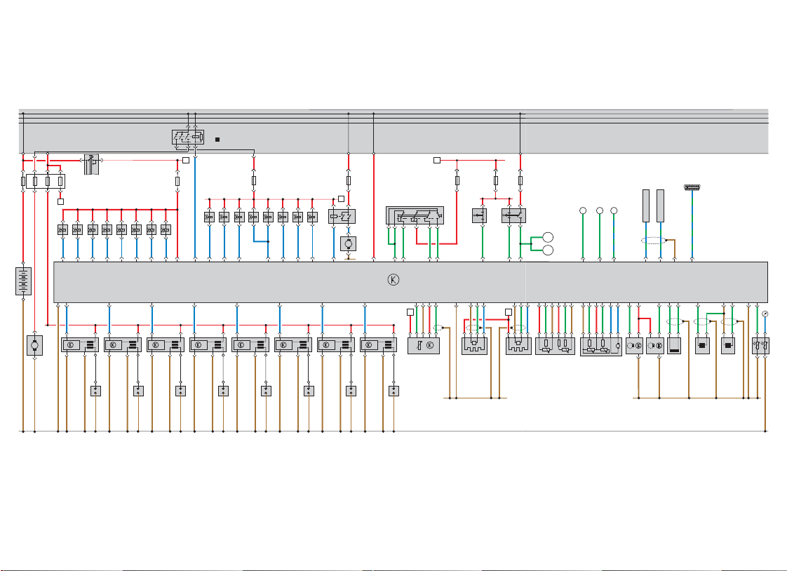
30
15
X
4
J17
X
ST3
ST4
S
S6
E45
*
F36 FF47
ST2
S10
S9
J220
+
--+--+-+-
Y
m
l
G70
Z
λ λ
G39 G108 G79 G185
Z19 Z28
1 32
CAN - BUS H
CAN - BUS L
M9
M10
+ +
G188 G187MG186
G163 G40
G28 G66 G61 G2 G62
N86
X
S116
N261
N156 N208
N112
S117
N205 N80
S130
Y
N145
N144
J299
M
V101
31
30 15
S2 S3
S1
S204
D
ST4
Z
N32
N31
N33N30 N83
N85
N84
+
A
-
M
N N128 N158 N163 N164 N189 N190 N191
G6
30
15
X
G3
P
Q
31
P
Q
P
P
Q
Q
P
Q
P
Q
P
Q
P
Q
31
SSP217_044
Page 40
40
En g in e M a n a g e m e n t
Q u ick-st a r t f u n c t ion s
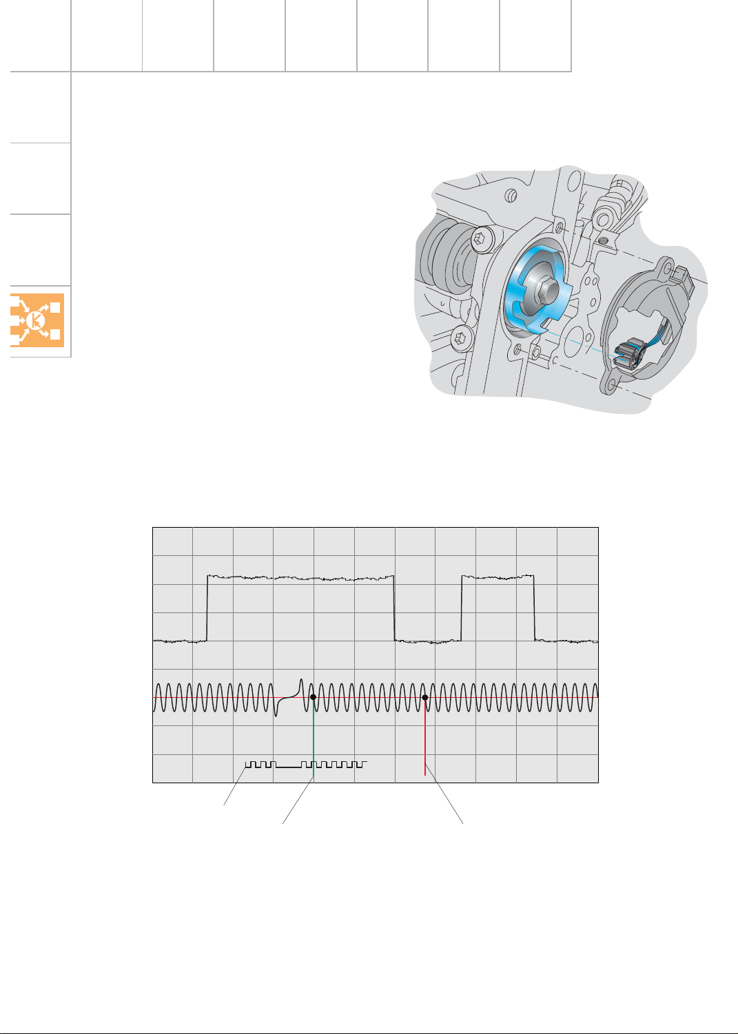
Camshaft position sensor G40 and G163
As with t h e V6-5V en gines , the new
V8-5V en gines also have two s e n s o rs for
d e term in in g th e p o s ition of t h e cam s haft
(G40 a n d G163).
The sender s ys tem with “qu ick-s tar t ro t or
ring“ alre a d y u s e d in th e 4- cylin d er 5-valve
e n gin es is im plemente d .
The quic k-s tart rot o r r in g h as two wid e a n d
two narro w s top s (tw o s m a ll a n d tw o la rge
windows ).
If a s top is in t h e Ha ll s e n s o r, t h e le ve l at t h e
s ig n al o u tput s e n s o r is high.
By u s in g d iffe rent sto p w id ths, it is p o s s ib le
to use th e s ignal fro m G40 tog et h e r w it h the
e n gin e s p e e d s e n d e r G2 8 to d e t erm ine the
camshaft positio n relative to t h e cra n ks h a ft
m o re quic kly.
SSP217_053
Wh e n the engine is s t art e d , t h e e n g in e c ontrol
u nit can thus dete rm ine the ignitio n TDC o f t h e
n e xt cylinder m ore quickly so tha t t h e e n g in e
s tart s m o re quickly (syn chronisatio n wit h the
1s t c ylin d e r is n o lo n g er n e c essary). Th is is
re fe rre d to as quick-s t art s ynch ro n is a t ion or
the quick-s tart fun ction.
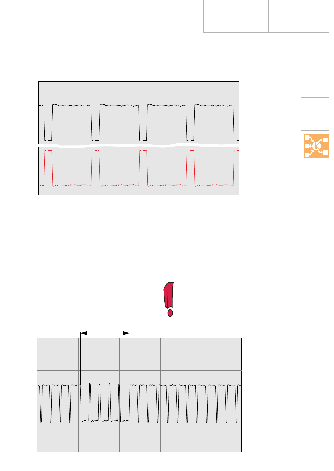
5 V/Div. 10 ms/Div
SSP217_062
Signal trace for engine speed sender G28 and Hall sender
G40 using oscilloscope function of VAS 5051
G40
G28
Sen de r whe el
Software re ference m ark
66o b e fo re TDC of 1st c ylin d e r
TDC of 1st c ylin d er
Automatic mode
*
Page 41

41
The ca m shaft pos itio n s en sor G16 3 is used to
m o n itor cam s haft adjustm ent a nd to
g e nera te a s u b s titu t e s ig n a l if th e G40 fails .
10 V/Div. 20 ms/Div
5 V/Div. 20 ms/Div
T
1
5 4 8 6 3 7 2
SSP217_061
The ca m shaft p os it io n s e n s o r G4 0 is
m o u n ted to c ylin d e r bank 2.
The ca mshaft pos itio n sensor G16 3 is
m o u n ted to c ylin d e r bank 1.
Engine run-down sensor
The ME 7.1 en gine m anagem ent system h as
a n e n g in e run-do w n s e n s o r. This d evice
s upport s t h e q uick-s tart fu n ction so th at fue l
in je ctio n c a n o ccu r before q u ick-sta r t
s yn chronisation .
The engine co n t ro l u n it rem ains a ctive for a
d e fin ed tim e after the ignition has been
s witc h ed off a n d , with t h e a id o f th e G2 8,
“m o n itors “ th e e n g in e a s it s lo w s to a s tan ds till.
The softw a re refere n ce m a rk is t he p oin t
from w h ich th e co ntrol unit co mm e n ces its
calcu la t ions to dete rm in e the ig n ition
p oint. It is about o n e t ooth afte r th e
h ard w a re refere n ce m a rk, w hich is
a p p ro xim ate ly 6 6˚ - 6 7˚ cr./shaft before
ig n ition TDC o f t h e 1st cylinde r.
Signal trace of engine speed sender G28, and
Hall sender G40 and G163
G16 3
G40
G28
Automatic mode
The positio n o f th e e n g in e m ech a n ics
(positio n o f th e next cylin d e r at ignitio n TDC)
is s tore d a n d is available th e next t im e th e
e n gin e is s ta rt e d . The ME 7.1 ca n im mediate ly
b e g in in je ction and has a fu e l m ixtu re re a d y,
which h a s a p os it ive e ffe ct o n s tart in g
b e haviour.
*
Page 42
42
En g in e M a n a g e m e n t
SSP217_041
Acc elera to r ped al
Kic kd own s wit ch
Ele c t ro n ic t h ro t t le f u n c t io n
Apart the following featu res, the elect ro n ic
thro ttle funct ions a re iden tic al to tho s e
d e scrib e d in S SP 1 98 .
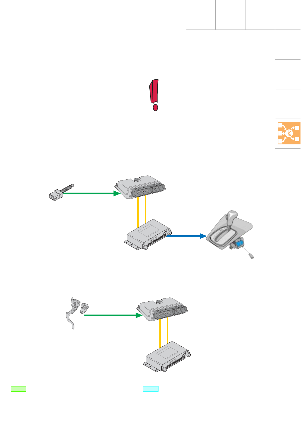
The pedal sender is u s e d in th e Audi A8 a n d
the acc e le ra tor p e d a l m od ule in the Au d i A6
to dete rm in e the re q u ire ments of the drive r.
Pedal sender (Au di A8)
A s eparate s wit ch is used to pro vide kickdown
in fo rm a tio n.
It is loca te d in the fo otw ell and d oubles as the
a cce le rat o r p e d a l st o p .
The full-th rottle a nd kickdow n p os itio n s m ust
b e calibra t ed a cco rdingly.
The ME 7.1 en gine m anagem ent system h as
to a larg e e xt e n t b een d escrib e d in S SP 1 98 .
The new funct ions a n d fe a ture s o f t h e s yste m
u sed in t h e V8-5V e n g in e a re d e alt with b elow.
Page 43

43
If the acc e le ra to r ped al m od ule or the
e n gin e control unit is ch a n g e d , th e
s witc h in g p o in t of the kickdown
s witc h m u s t b e repro g ra m med using
the diagnostic teste r – see th e r epair
m a n u a l.
SSP217_060
100 %
0
G79
G185
5,0
20 % 40 %
60 % 80 %
Accelerator pedal module (Au di A6)
No s ep arate swit ch is used to pro vid e kic kd own inform at io n . In t h e case of a uto m at icg e arb o x veh icle s , th e a c celer ato r pedal sto p
is replace d b y a pre s s u re e lem ent. Th e
p re s s u re elem ent genera tes a “m e chanica l
p re s s u re point“ wh ic h g ive s t h e d river t he
“kickd own feeling“.
If the drive r activa t e s the kickdown , th e fullthro ttle volta g e o f th e a ccelerato r pedal
p osition senders is e xce e d e d . If a volta g e
d e fin ed in the engine co n t ro l un it is re a che d ,
this is in terp rete d a s a kickd o w n a n d t h e
in fo rm atio n is sent to t he a uto m atic g e a rb ox
via t h e CAN b u s . Th e kickd own swit ching
p oint can on ly be teste d u s in g d iagn os t ic
teste rs.
Kic kd own r ange
Acc elera to r ped al
fin al sto p
Full-th rot tle sto p
(m ech a n ical)
Driver to rqu e ran ge
Signa l volta g e (V)
Acc elera to r ped al travel
Page 44

44
CA N b u s int e rfa c e s
En g in e M a n a g e m e n t
ESP control unit
ASR r equest
ASR inte rventio n t o rq u e
(TARGET)
Bra ke p ed al sta t us
ESP in t erve n t io n
Road speed
MS R req u e s t
MS R in terve n t ion torque
CAN-high
CAN-low
Dash panel insert
Self-diagnosis info
Road speed
Mile a g e
Coola n t t e m p e rat u re
Oil t e m p e ratu re
Imm o b ilis e r
Steering angle sensor
Ste e ring wheel angle
(used for p reco n tro l o f th e
id lin g s p e e d c ontrol d e vice
a nd fo r ca lculatin g engine
tor que based on th e pow e r
re q u irem ents of the powe r
s teerin g s ys t e m )
Gearbox cont rol unit
Adapta tion re le a s e
Idle ch a rge co m pens at io n
Swit ch off com p re s s o r
Idling speed, targ e t s p e ed
Engine tor que (TARGET)
Em e rg en cy running p ro g ramm e s (in fo via self-diagnosis)
Ge ar change act ive / in a ctive
Selector le ve r positio n
To rqu e c o n ve rte r/g e arb o x
g uard
To rqu e c o n ve rte r clu t ch
s tatu s
Curre n t g e a r an d
targ e t gear
Engine control unit
Inta ke air tempera ture
Bra ke light s w itch
Bra ke p ed al swit ch
Thrott le va lve angle
Electron ic t h ro t tle warn in g
la m p in fo
Driver tor que ra n g e
Em e rg en cy running p ro g ramm e s (in fo via self-diagnosis)
Acc e le ra tor p e d a l p o s ition
CCS swit ch positio n s
CCS ta rget s pee d
Altit u d e in fo rm ation
Kickd own inform at io n
Swit ch off com p re s s o r
Compre s s o r ON/OFF
(ch e ck-back signal fro m
b id ire ctional in terfa ce)
Fuel con s u m ptio n
Coola n t t e m p e rat u re
Clutch p e d a l s w itch
Idle dete c tion
Engine s p e ed
Engine tor que (ACTUAL)
Imm o b ilis e r
Page 45
45
In the Au d i A8, dat a b e t ween th e en gine
con trol unit and th e ot h e r c o n trol u n its is ,
with th e e xce p tion of a fe w in t erfa ce s ,
e xchan ge d via the CAN s ys tem .
The syste m overvie w s h o ws the inform at io n
which is pro vid e d b y t h e e n g in e c ontrol u n it
via t h e CAN b u s , an d re ceived and u s ed b y
the co n n e cted co n t ro l u n it s .
The followin g tw o e xa m p le s simplify t h e
com ple xity of the CAN b u s n e twor k.
Selector lever lock:
De tailed inform at io n c once rning the
CAN d a t a b u s c an b e fo u n d in
SSP 18 6.
Kickdow n (for example, Audi A6):
Inform a t ion which is sent by
the engine co n t ro l un it.
Inform atio n which is re ce ived
a nd e va lu a ted by the engine
con trol unit.
Acc elera to r ped al mod ule
G79 /G185
Engine co n trol unit
J 220
Ge arb o x con trol un it
J 217
Bra ke lig h t swit ch
F/F47
Engine co n trol
u nit J2 20
Ge arb o x con trol un it
J 217
Sele ctor le ver lo ck
s oleno id N110
Page 46

46
En g in e M a n a g e m e n t
In the A6 , t h e re will be n o CAN d a ta e xch ange
with th e d a s h p a n e l in s e r t when pro d u ctio n
of t h e m o d e l b e g in s . For t h is rea s o n , t h e A6
h as the followin g inte rface s in additio n t o
thos e of the A8:
Pin 43 Im m obilis e r/self-diagnosis
Pin 19 Coolant te m p e ratu re signal
Pin 81 Fue l co n s u m p t ion s ig n a l
Pin 54 Roa d spee d signal
Pin 37 Engine speed signal
Pin 48 Warn in g la m p for e le ctronic
thro ttle
A d d itio n a l sig n a ls/
in t e rfa c e s
In the Au d i A8, th e fo llo w in g in t erfa c e s a ls o
e xis t fo r d a t a e xchange via CAN b u s :
Pin 67 Crash signal
Pin 43 K-lin e /d ia g n ostic c o n n ectio n
Pin 41 Com p re s s o r ON/OFF
Pin 40 Air c o n d itioner re q u irem ent signal
Mo s t of t h e in terfa c es a n d a d d itional signals
of t h e ME 7 .1 are d e s c rib ed in SSP 19 8. On ly
the new inte rface s an d additio n a l s ignals are
d e alt with b e lo w.
Page 47
47
SSP217_059
5 V/Div. 0,5 s/Div.
Recorder mode
Cra s h signal
w ith tr igger ing
Trig g e rin g ra nge
Crash signal
SSP217_058
T
5 V/Div. 0,1 s/Div.
In the event o f a crash where the belt
tension er s /a irbags are t rig g e red, the engine
con trol unit deac tivates act u ation of the fuel
p u m p re lay. Th is p reve n ts exces sive q ua ntitie s
of fu el escap ing if t h e fu el sys tem is d am aged.
The cras h s ignal is a s qu are -wa ve signal with a
s p e cific s ig n a l ratio (h ig h le ve l to lo w le ve l).
The signal is tra n s m it ted con t in u ously b y t he
a irb ag co n tro l u n it .
In the event o f a crash, the signal ra t io is
in ve rte d for a d e fined perio d o f tim e. Durin g
this perio d, the signal ra tio is in vert ed rela tive
to th e s ta n d a rd signal s o that t h e s u p p ly o f
fu e l is shu t o ff until th e e n g in e is re s tart e d .
In addition , th e “c ras h s h u t -off“ fault is
s tored.
The fault e nt ry can only be d e le ted
u sin g the diagnostic t ester.
Automatic mode
Sta n d ard s ig n al
Cra s h triggerin g
Signal traces for crash signal using oscilloscope
function of VAS 5051
Page 48

48
En g in e M a n a g e m e n t
Self-diagnosis
The cras h signal is checke d w ith re s p e ct to
the plausibility of the crash signal and
vo ltage.
Effect of fault
If the “cras h shu t -off“ fault is sto red in the
e n gin e control unit and is n ot erased, the fu e l
p u m p is not p rim e d w ith fu e l w hen the
ig n ition is s witc h e d o n (n o p re co m pre s s ion is
g e nera ted in t he fu e l s yste m ). This m ay re s u lt
in d e la ye d s t a rtin g of the engine.
Furt h e r in for m a tion con c e rn ing th e
fu e l s h u t-off s ys t e m c a n b e fo u n d
u nder Ve h icle Safet y in SS P 207 a n d
SSP 21 3.
The fuel s h ut-off s yste m will not b e
in corp ora t ed in t h e Au d i A6 a n d A8
u ntil m o d e l ye a r 2000.
Self-diagnosis
The air conditio n e r re quire m e n t in t erfa c e is
n ot m onito red b y the self-d ia g n osis s ys tem .
Effect of fault
The idling s p eed is n o t in cre ased which
re s u lt s in a re duct io n in t h e o u tput of co o l a ir
when th e en gine is id lin g .
The air condit ioner requirement interface
In the ca s e o f a high air conditio n e r outp u t
re qu ire m ent, th e idling s p e ed o f t h e e n g in e is
in cre ased to increas e t h e o u tput of co o l a ir
from the air conditio n e r co m pre ssor.
In som e cases , air c ondition ing re q uire m en ts
m a y b e suc h that th e “air c o nditione r re q u irem e n t“ in t erfa c e is a ls o s wit ch ed to “h ig h “ at
the air conditio n e r operating and dis p lay u n it
where upon the engine co n t ro l u n it is inform e d o f th e in creas e d o u tput re q uire m en t.
This ca n be te s t e d u s in g t h e “Re a d m ea s u re d
va lu e b lo ck“ fu n ction of the diagnosis te s t e r
(see re p a ir m anual).
It is im p o rta n t to note t h a t the funct io n fo r
in cre asing the idlin g s pee d is not a vailable fo r
a ll e n g in e va riants , eve n if th e s ig n a l is sent
to th e e n g in e co n tro l u n it.
Page 49

49
Se rv ic e
A n um b e r o f n e w s p ecial to ols are re qu ire d b y
the Se rvice depart m e n t fo r repairin g th e
V8-5V en gine.
Tensioning roller spanner
Order No .T400 09
Camshaft retainer
Order No .T400 05
SSP213_007
SSP213_008
SSP213_009
Thrust pad
fo r c ra n ksha ft o il seal
Order No .T400 07
Page 50

50
N o t e s
Page 51

De ar Re a d e r,
This self-stu dy p ro gr am m e has allowed yo u to fam ilia rise yours e lf wit h the n ew te ch nica l fe atu res
of t h e V8-5V e n g in e .
Ou r aim is to m a ke t h e conte n t o f t h e s e lf-s t u d y p rog ram m e m ate rial as in teresting as possible.
This is why we wa n t to g ive yo u t h e o p p ortu n ity to te ll us your o p in io n s a n d s u g g estion s for
fu ture s e lf-s t u d y p rog ram m e s .
The followin g qu e s tionnaire is inte n d e d to assist you in d oing this.
Send your com m e n ts a n d s u ggestio n s t o the fa x n u m b e r 0049/84 1 89 36 36 7 .
We thank yo u fo r your s u p p ort .
The Technical Training Service Team
51
Page 52

 Loading...