

Page 1
Service.
For internal use only
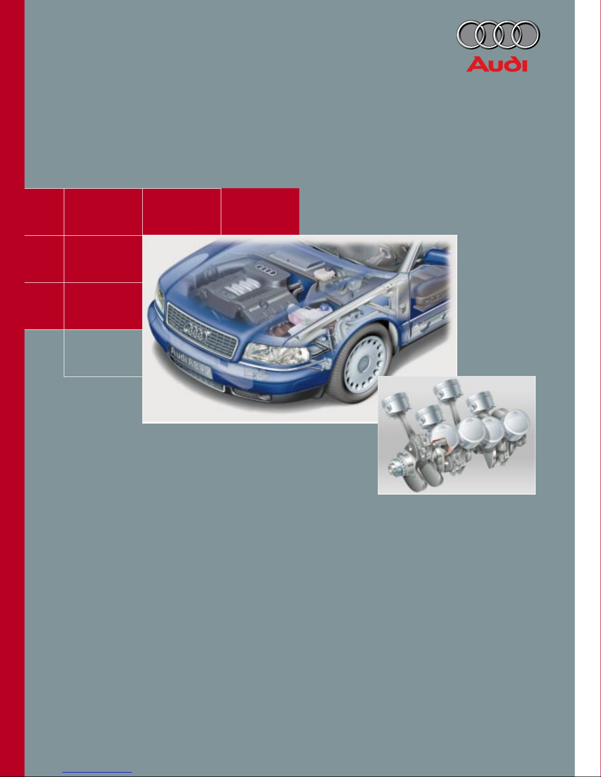
The V8-5V Engine
Construction Features and Functions
Self-Study Programme 217
217
Page 2
2
SSP217_048
AUDI has been producing advanced 8-cylinder
engines since 1988. Their capacity has incr eased
from 3.6 l to 4.2 l.
The V8 engine in combination with Aluminium
Space Frame technology was the tec hnical basis
for Audi's breakthrough into the luxury class.
Steps to enhance the value of the Audi A8 have
included the redesign of the V8 engine.
The new V8-5V engines are now also available for
the Audi A6 model range.
Page 3

3
Engine - Motronic Subsystems
Variable intake manifold ...................................................... 27
Secondary air system ........................................................... 32
Content
Introduction
Engine - Mechanics
Crankgear .............................................................................. 6
Engine mounting .................................................................. 9
Engine lubrication ................................................................ 10
Cooling circuit ....................................................................... 16
Cylinder head
Five-valve technology ............................................. 19
Roller rocker ............................................................ 20
Camshaft adjuster .................................................. 22
Toothed-belt drive; cylinder-head seal ................. 24
Cylinder-head cover seal ........................................ 25
Exhaust manifold .................................................... 26
Technical data ....................................................................... 5
The self-study programme is not a repair manual!
The self-study programme provides you with information
concerning the engine's construction features and functions.
New! Caution!
Important!
Page
When carrying out maintenance and repair work, it is essential
to use the latest technical literature.
Engine Management
System overview ................................................................... 36
Function diagram ................................................................. 38
Quick-start functions
Camshaft position sensor ...................................... 40
Engine run-down sensor ........................................ 41
Electronic throttle function ................................................. 42
CAN bus interfaces ............................................................... 44
Additional signals / interfaces ............................................ 46
Service . . . . . . . . . . . . . . . . . . . . . . . . . . . . . . 49
Page 4

4
New features
– Five-valve cylinder head with roller rocker
– Camshaft adjustment
– 3-stage variable intake manifold
– Engine management system, Bosch ME 7.1
– Electro-hydraulic engine mounting
Modifications
– to crankcase and crankgear
– to oil circuit
– to cooling circuit
V8-5V Engines
Introduction
SSP213_073
Major modifications were made to the
V8 engines during the course of further
development.
Emphasis was placed on the following
development objectives:
– compliance with future exhaust-emission
regulations
– reduction of fuel consumption
– increase in torque and power
– improvement of comfort and convenience
– reduction of engine weight
– increased use of shared components for
the AUDI engine series.
The following new f eatures and modifications
have been incorporated in the V8 4-valve
engine.
Page 5
5
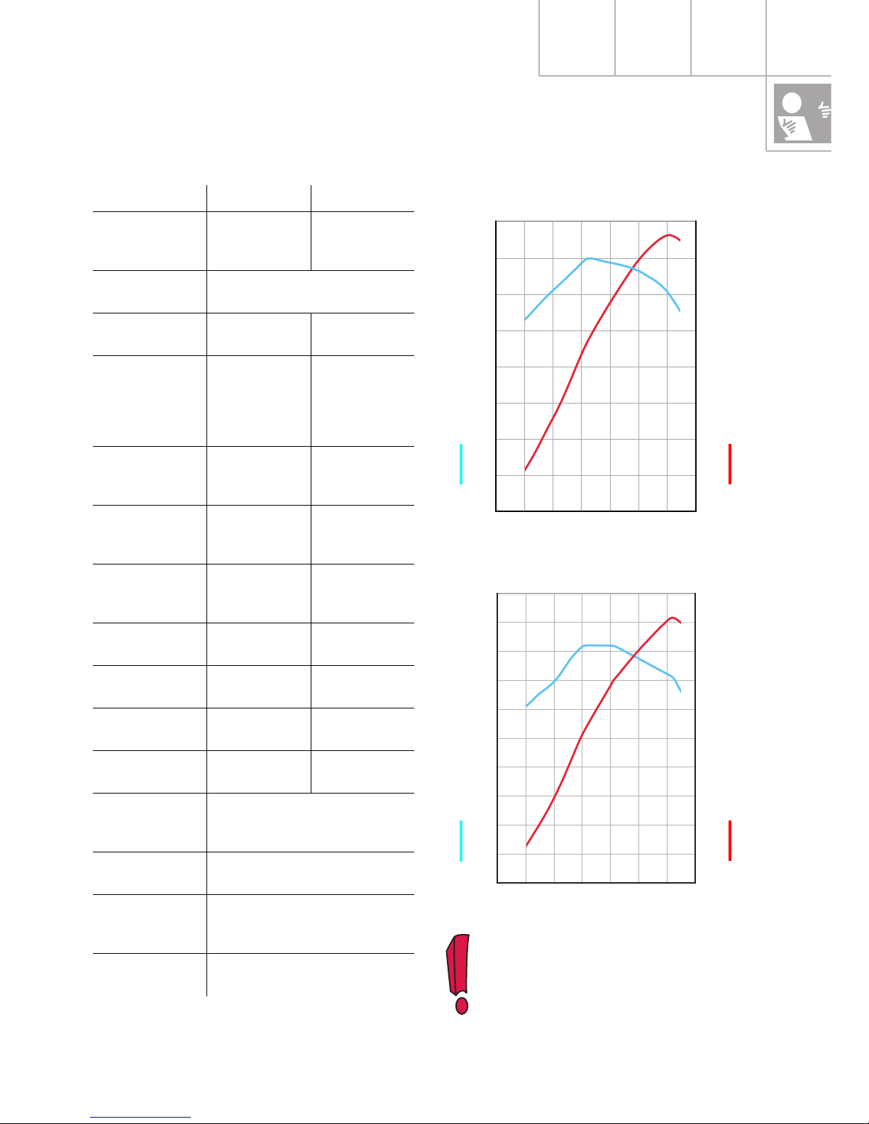
Technical data
The specified power data is only
possible if 98 RON fuel is used.
A reduction in power output must be
expected if 95 RON fuel is used.
3.7 l V8-5V engine
4.2 l V8-5V engine
0
50
100
150
200
250
300
350
400
450
500
0
25
50
75
100
125
150
175
200
225
250
0 1000 2000 3000 4000 5000 6000 7000
0
50
100
150
200
250
300
350
400
0 1000 2000 3000 4000 5000 6000 7000
0
25
50
75
100
125
150
175
200
SSP217_004
SSP217_005
Torque (Nm)
Speed (rpm)
Power output (kW)
Torque (Nm)
Speed (rpm)
Power output (kW)
3.7 l 4.2 l
Engine code AQG AQF (A8)
ARS (A6)
Design V8 engine with 90o V angle
Capacity 3697 cm
3
4172 cm
3
Power output 191 kW
260 hp
at
6000 rpm
228/220 kW
310/300 hp
at
6000 rpm
Specif. output 51.6 kW/l
70.3 hp/l
54.6 kW/l
74.3 hp/l
Torque 350 Nm at
3200 rpm
410 Nm at
3000 rpm
Specif.
torque
94.7 Nm/l 98.3 Nm/l
Bore 84.5 mm 84.5 mm
Stroke 82.4 mm 93.0 mm
Compression
ratio
11:1 11:1
Weight 198 kg 200 kg
Engine
management
Motronic ME 7.1
Fuel 98/95 RON
Firing
sequence
1 - 5 - 4 - 8 - 6 - 3 - 7 - 2
Exhaust-emission standard
EU 3
Page 6
6
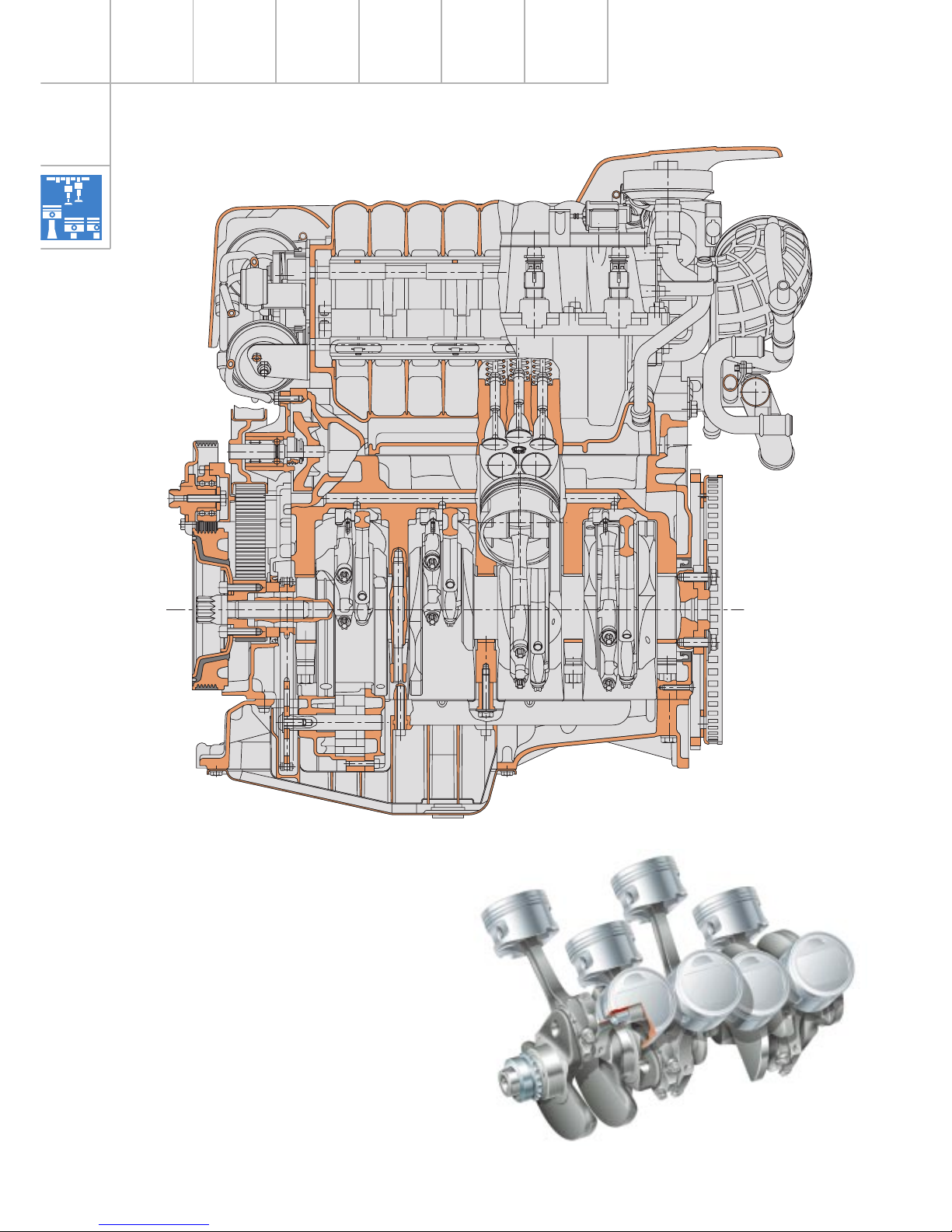
Engine - Mechanics
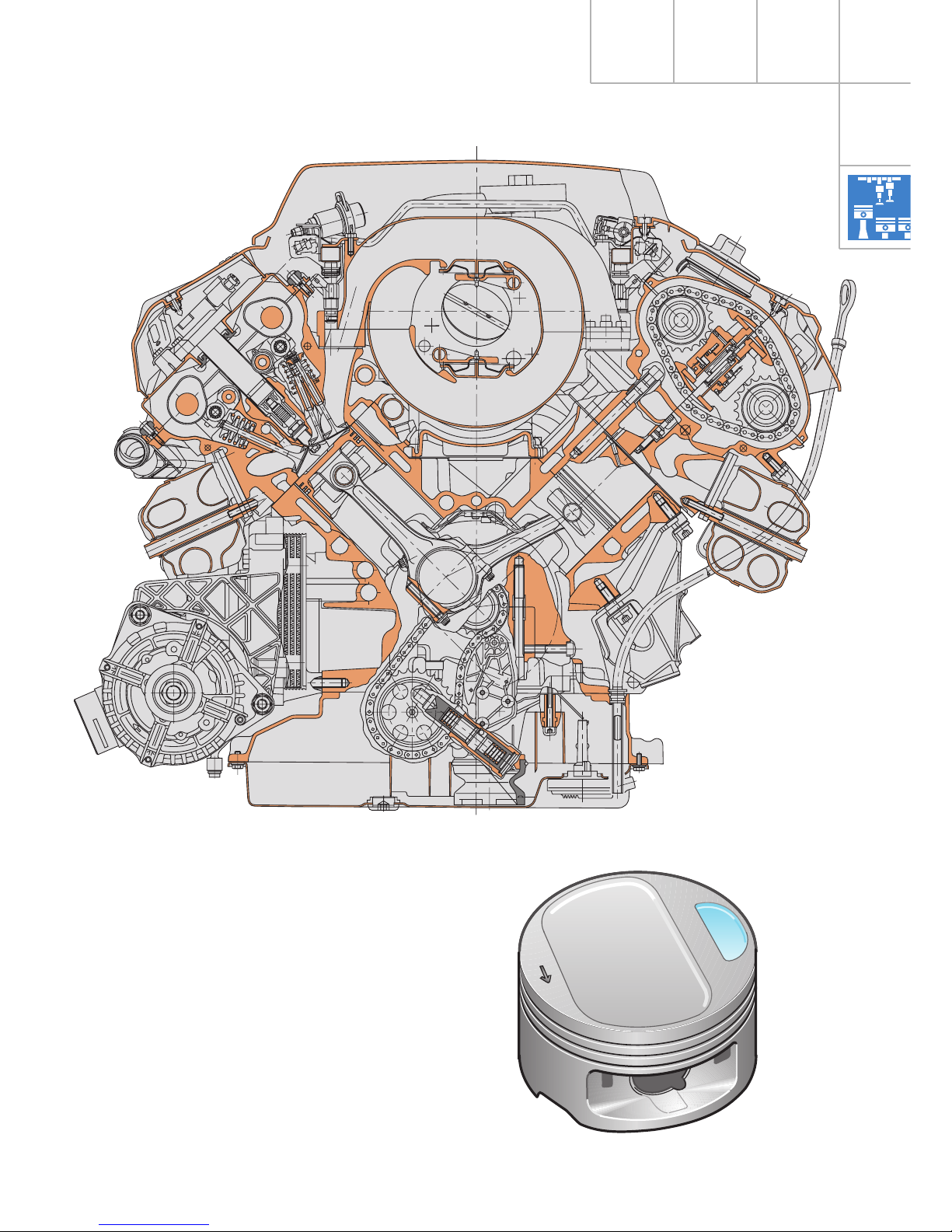
Crankgear
The crankcase has been adapted to the
modifications made to the oil supply system
and cooling circuit.
Cracked-steel conrods have been used for the
3.7 l engine since 1995 and are now also
being used for the 4.2 l engine.
The conrods are shared components used in
both the 2.4 l and 2.8 l engine.
SSP217_054
SSP217_006
Page 7
7
Owing to the design of the valve recesses, the
pistons are specifically intended for use in the
appropriate cylinder bank only.
SSP217_055
SSP217_002
Page 8
8
Engine - Mechanics
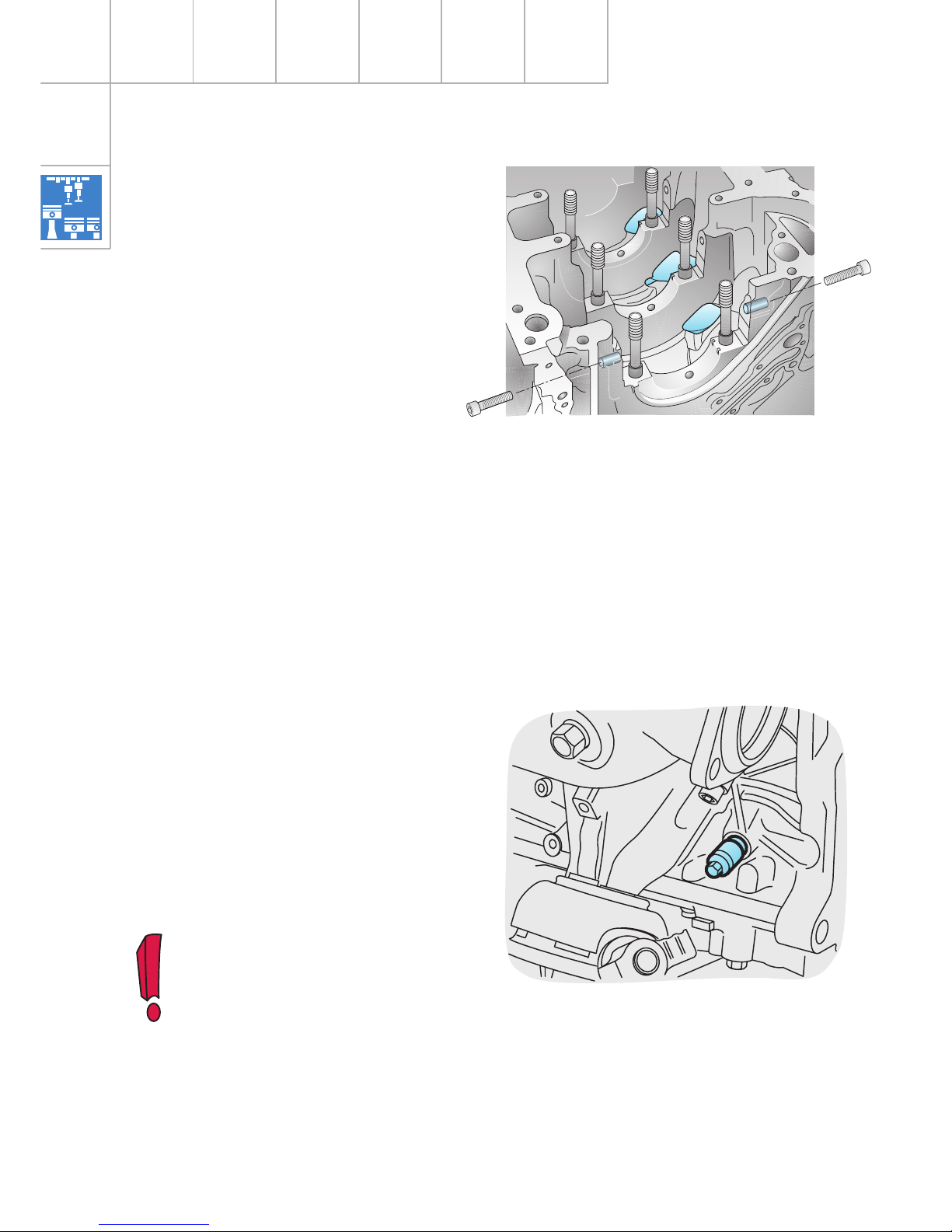
The locking mandr el (V.A.G 3242) used for the
V6 engines is also used for locking the
crankshaft. It is applied to the crank web of
the 4th cylinder and is used for basic engine
adjustment and also as a counterhold for
loosening and tightening the central bolt of
the crankshaft.
SSP217_009
The 5th cylinder must be set to
ignition TDC.
SSP217_007
Wide, milled ventilation recesses above the
thrust bearings reduce pumping losses.
Bolts are also inserted at the side of the two
front crankshaft bearing caps to improve
running smoothness
(see SSP 198, page 6).
Page 9
9
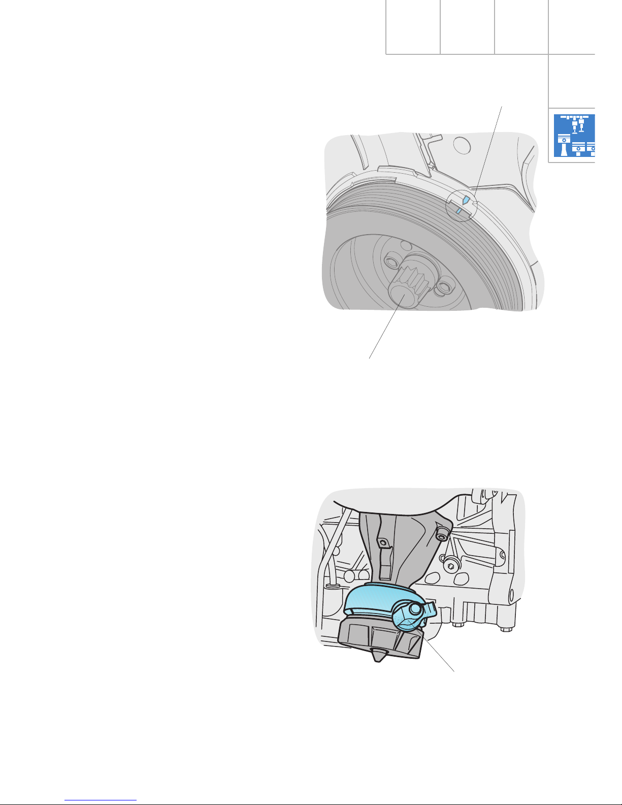
The central bolt does not have to be
unscrewed for the vibration damper to be
removed.
The marking indicates the ignition TDC of the
5th cylinder.
SSP217_050
Central bolt
Marking
Engine mounting
To enhance driving comfort, hydraulic engine
mounts with electrical activation are used for
the 8-cylinder engines.
They function in the way as described in
SSP 183/16.
The mounts are activated by the engine
control unit according to engine speed and
vehicle speed.
Electrical connection
SSP217_039
Page 10
10
Engine - Mechanics
SSP217_010
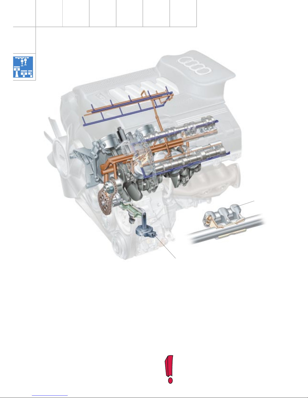
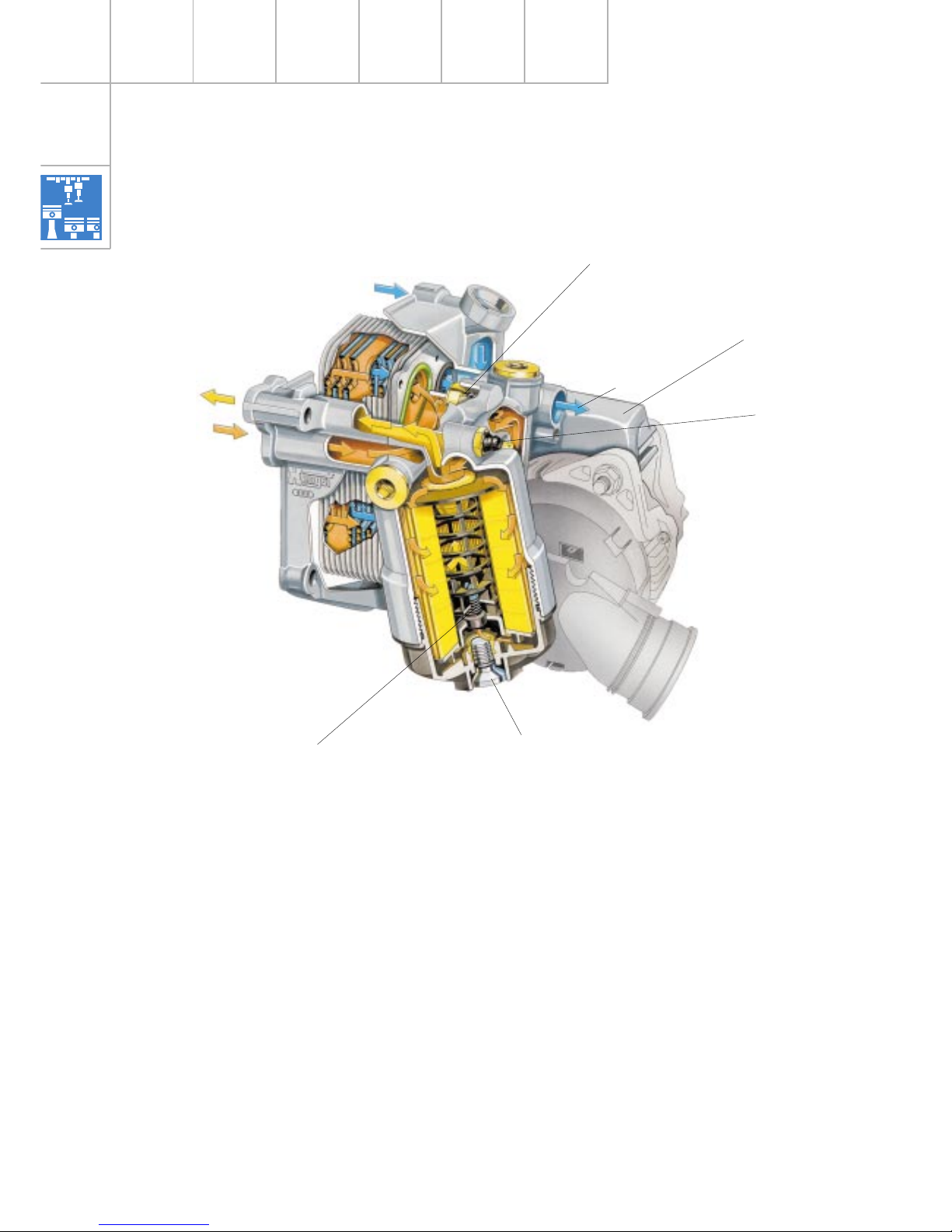
A duocentric oil pump driven by the crankshaft via a chain replaces the previously used
external gear oil pump.
The duocentric oil pump extends deep into
the oil sump. The low suction height means
that the oil pressure can build up quickly,
especially with cold-starts.
The oil-pressure contr ol valve is located in the
oil pump housing. The “diverted“ oil is led off
to the intake side of the oil pump. This helps
optimise the level of efficiency.
In the intake spindle shafts, there are 5 oil
bores per triple roller rocker. Three oil bores
each supply one hydraulic tappet. Two oil
bores supply the oil-spray bor es integr ated in
the roller rocker to lubricate the rollers. The
oil-spray bores are only opened when the
roller rockers are actuated. This results in a
reduction of the amount of oil required in the
cylinder head.
Oil-level sensor
Triple roller rocker
The roller rockers are described on
pages 20 and 21.
Engine lubrication
Page 11

11
BA
A
B
B
P
A
A
SSP217_011
Throttle
Cylinder bank 1
Oil retention valves
Spray jet valve
Bypass valves
Oil filter module
Oil sump
Oil pressure control
valve
Camshaft
Cylinder bank 2
Oil flow (pressurised)
Oil flow (non-pressurised)
Throttle
Duocentric oil pump
Filter element
Oil cooler
Slight modifications have been made to the
oil circuit in the cylinder heads.
The oil circuit for cylinder bank 2 shown in the
illustration is the oil circuit that has been
used since the introduction of the new model.
Cylinder bank 1 shows the modified oil
circuit.
Page 12
12
Engine - Mechanics
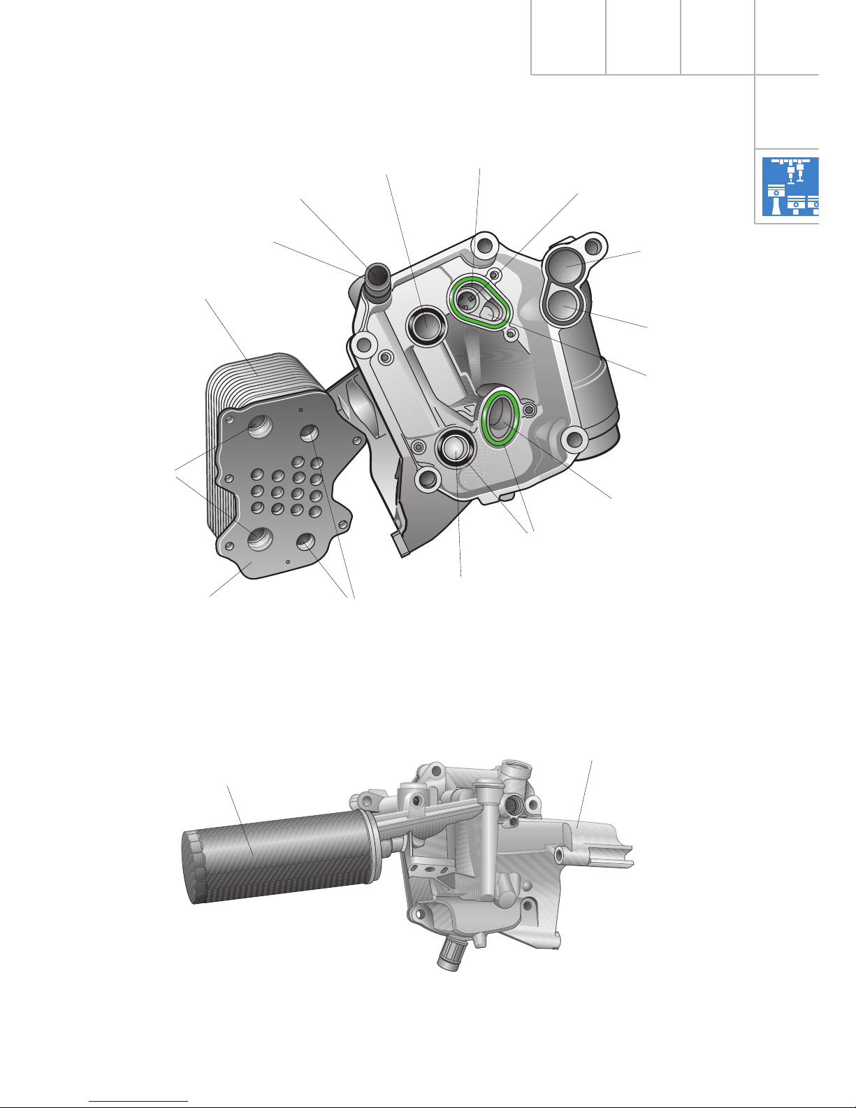
The oil filter module contains the oil filter
and oil cooler. It is also used to hold the
alternator.
SSP217_013
Oil cooler bypass valve
Alternator mount (part
of oil module)
Coolant supply
Coolant
return
Oil supply
Oil return
Oil filter module
(A8)
Oil pressure switch
Drain plug
Filter bypass
valve
As was previously the case, the oil cooler is
designed as a coolant-to-oil heat exchanger.
The “housing-less“ oil cooler is bolted to the
oil filter module using an O-ring seal to form a
single unit.
Page 13
13
SSP217_014
Oil cooler
O-ring seal
Sealing surface
(Oil cooler)
Coolant supply
(from engine)
Oil duct
Coolant
return
Oil cooler bypass valve
Oil return
(to engine)
Oil supply
(from engine)
Oil cooler
return
Oil cooler
supply
Plastic connection
SSP217_003
Oil filter cartridge
Alternator
holder
For space reasons, the A6 oil filter module is
fitted with an oil filter cartridge.
Oil filter module
(A8)
Oil filter module
(A6)
Engine oil
Coolant
Coolant supply
Page 14
14
Engine - Mechanics
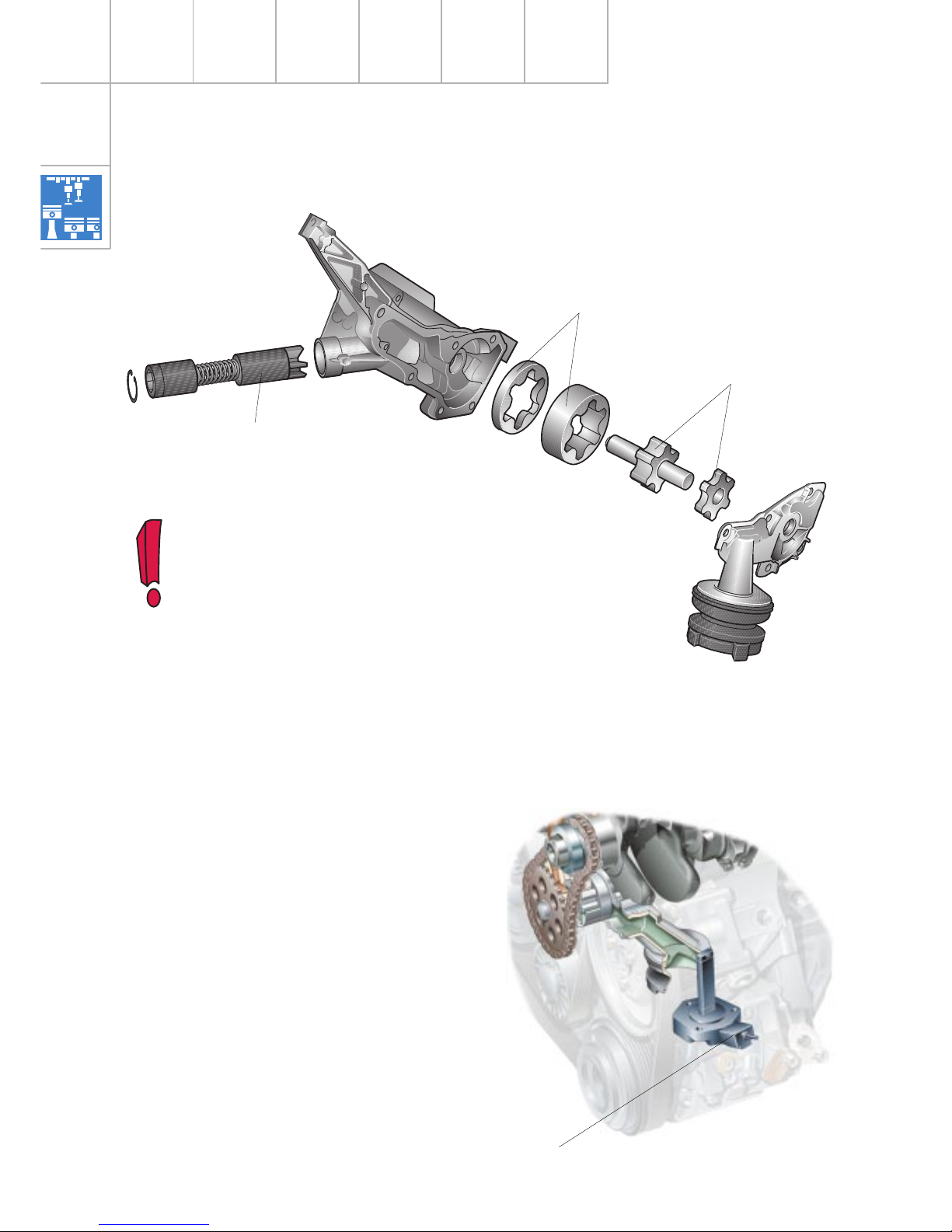
The pitch of the internal gear and the
external runner has no functional
significance and is determined by
production engineering factors.
To ensure that the assembly
functions correctly, the narrow gears
must not run together on the same
plane.
SSP217_012
External runner
Internal gear
Oil pressure control valve
Duocentric oil pump
Oil level sensor
The oil level sensor functions as an information sender which allows the flexible service
interval to be calculated and the oil level to be
displayed in the dash panel insert.
Further information can be found in SSP 207
(from page 84 onwards) and SSP 213 (from
page 55 onwards).
SSP217_063
Oil level sensor
Page 15

15
Notes
Page 16
16
Engine - Mechanics
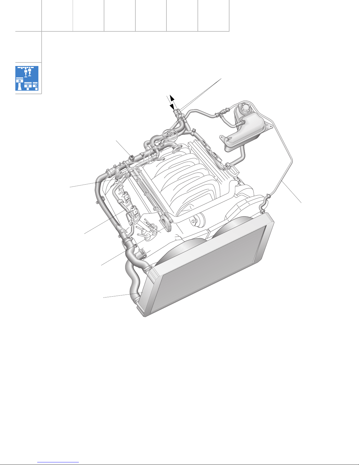
The flow direction of the coolant has been
changed in the new V8 5-valve engines.
As with the V6 engines, the coolant leaving
the cylinder heads merges in the rear coolant
pipe from where it is then led off to the
cooler.
SSP217_015
Cooling circuit
(Example: A8)
Return from oil
cooler
Heat exchanger / valve
unit
Coolant temperature
sender G2 and G62
Radiator fan thermo
switch F18/F54
Coolant pipe
(return for heater, oil
cooler and expansion
tank)
Breather pipe
New coolant pipe to
cylinder head
(small cooling circuit)
Page 17

17
Oil cooler return
The new coolant pipe alters the coolant flow
in the „small“ cooling circuit.
SSP217_016
Coolant pipe
(return for heater, oil cooler
and expansion tank)
New coolant pipe to
cylinder head
(small cooling circuit)
To expansion tank (A8)
Coolant return
Heat exchanger (A6)
Breather pipe
(to expansion tank)
Coolant supply
for heat exchanger
to vehicle radiator
Coolant return
Heat exchanger (A8)
to expansion tank (A6)
Coolant temperature
sender G2 and G62
Coolant pipe (rear)
Page 18

18
Previous design:
The coolant thermostat is connected to the
“small coolant circuit“ via two holes in the
cylinder crankcase (see Fig. 217_017).
The holes are directly connected to the
cylinder-head water jacket (1st cylinder) and
the water jacket of the cylinder crankcase. The
heated coolant flows from the 1st cylinder to
the coolant thermostat.
SSP217_018
Engine - Mechanics
New design - modified components:
– Cylinder head in bank 1 modified
– Additional coolant pipe
– Rear coolant pipe modified
The connection in the cylinder head to the
water jacket (cylinder crankcase) has been
split (see Fig. 217_019).
The coolant from the rear coolant pipe is
forked by the new coolant pipe (mixture from
all cylinders) and then passes through the
cylinder head to the two holes which lead off
to the coolant thermostat.
This ensures uniform temperature control.
The function of the cylinder head is to
connect the coolant pipe to the two holes
leading off to the coolant thermostat.
SSP217_019
SSP217_017
New coolant pipe
New design
From radiator
To coolant pump
Coolant thermostat
Coolant pipe
(return for heater, oil cooler
and expansion tank)
Page 19

19
The rockers are made of die-cast aluminium
in order to keep inertia forces as low as
possible. As a result, the valvegear is able to
function reliably at engine speeds of up to
7200 rpm.
The use of roller rockers has not only meant a
considerable reduction in frictional losses in
the valvegear, but has also halved the oil
delivery rate in the cylinder heads. This also
has a positive effect on the degree of
efficiency.
Five-valve technology is now also being used
in the V8 engines.
Roller rockers ar e being used for the first time
in the enhanced five-valve cylinder head.
This considerably reduces frictional losses in
the valvegear which, in turn, significantly
improves efficiency.
SSP217_020
Cylinder head
Five-valve technology
Page 20

20
SSP217_023
Engine - Mechanics
Roller rocker
Exhaust valve
Every valve has a hydraulic valve lifter which
is integrated in the rocker. The rockers are
supported by a spindle shaft which is also
used to supply oil to the bearings and the
hydraulic valve lifters.
The two exhaust valves are actuated by a twin
roller rocker.
The single cam actuates the rocker by means
of a roller located between the rocker arms.
SSP217_022
Spindle shaft,
also used to
supply oil
Exhaust valve
20.2˚
Roller located between
rocker arms
Twin
roller rocker
Single cam
Oil spray hole
The individual hydraulic valve lifters
can be replaced without the rockers
needing to be removed.
Page 21

21
Inlet valve
Tolerance compensation for inlet
triple RR (roller rocker)
To ensure uniform compression
between the two cams and rollers
of the roller rockers, the spindle
shaft of the inlet roller rocker is
convex in shape in order to
compensate alignment and
component tolerances. This
prevents the roller rockers from
“tilting“.
SSP217_024
Double cam
Hydraulic valve lifter
with slide pad (hydraulic
valve tappet)
Oil duct
Spindle shaft
Inlet valve 2
14.9˚
Inlet valve 1 and 3
21.6
o
SSP217_021
Cylinder head
The three inlet valves are actuated via a triple
roller rocker.
A double cam actuates the rocker by means
of two rollers between the rocker arms.
SSP217_025
Triple roller rocker
Cams
Rollers
Spindle shaft
axis (target)
Spindle shaft
axis (actual)
Camshaft axis
For the sake of clarity, the
tolerance of the spindle shaft
relative to the camshaft has
been greatly exaggerated in
the illustration.
Page 22

22
Engine - Mechanics
Camshaft adjuster
(cylinder bank 1)
In the case of the new V8 engines, an
interlock function and an oil reservoir were
added to the proven system during the
course of further development.
These new features prevent vibrations in the
chain drive which has a positive effect on
acoustic behaviour during the start phase.
The camshaft adjustment system, a feature
incorporated in Audi's current range of
engines, is also used in the new generation of
V8-5V engines.
When the engine is switched off, no oil
pressure is applied to the chain tensioner and
camshaft adjuster.
Owing to the Ferraria effect in the chain drive
when the engine is started, vibrations which
generate noise occur until sufficient oil
pressure has built up.
SSP217_026
Chain tensioner slide pad
Locking pins for
starting phase
Slide pad adjuster
Camshaft adjustment
valve N205
Hydraulic cylinder with
switching piston
The principle of camshaft
adjustment is described in SSP 182.
Oil reservoir
Tensioning piston
Adjuster piston
Page 23

23
BBA
A
BBA
A
B
A
BA
SSP217_027
Engine off:
If there is no oil pressure,
a spring-loaded locking
pin is pushed into the
detent slot of the
adjusting piston. The
adjusting piston is then
locked.
Oil return
Oil supply
Oil reservoir
Locking pin
Adjusting piston
SSP217_029
SSP217_028
The camshaft adjuster is locked in the
“Retard position“.
Engine running:
Once a defined oil pressure has been reac hed,
it acts on the surface of the locking pin, i.e.
against the resistance of the spring.
The locking pin releases the adjusting piston
so that the engine control unit can adjust the
timing in the “Advance“ direction.
Control ducts
Lubrication and
breather hole
Engine start:
The adjusting piston is locked until sufficient
oil pressure has built up. This prevents
vibrations in the chain drive and, therefore,
noise generation.
Oil reservoir
The oil reservoir ensures that the pressure
chamber of the tensioner piston is filled
during the non-pressurised phase of the
starting cycle.
This also has a positive effect on acoustic
behaviour when the engine is started.
A hole in the top of the oil reservoir allows air
to escape and supplies the chain with oil.
Retard setting
(Basic and power setting)
Advance setting
(Torque setting)
Page 24

24
Engine - Mechanics
Toothed-belt drive
The toothed-belt drive is identical to that of
the V6-5V engine. The V8-5V engine is also
fitted with a stabilising roller.
The components are largely identical to those
of the V6-5V engine.
Cylinder-head seal
The new V8-5V engines have a multi-layer
metallic cylinder-head seal already used in
the 4 and 6-cylinder engines. This seal
replaces the soft seal used in previous
models.
SSP217_038
Stabilising roller
It consists of 3 individual metallic layers.
The two outermost layers are treated with a
special coating.
Advantages:
– Very good settling behaviour
– Improved durability
SSP217_056
Coating
Eccentric roller
Page 25

25
The above-mentioned measures means that
the cylinder head cover is not dir ectly coupled
with the cylinder head. It is, therefor e, “insulated“ against vibrations generated by the
engine.
SSP217_040
Cylinder head
cover
Decoupling element
(short)
SSP217_043
The securing bolts must be tightened
uniformly in the specified order to
prevent distortion of the cylinder
head cover and to ensure that the
seal is completely air-tight.
Always refer to the information given
in the repair manual.
Cylinder-head cover seal
The thin-wall cylinder head covers are made
of a die-cast magnesium alloy . A seal concept,
which decouples the cylinder head cover from
the cylinder head, improves the acoustics of
the engine.
The bolted connections of the cylinder head
cover have decoupling elements.
A seal, which is similar to a radial shaft oil
seal, is used for the spark-plug shaft.
735
119
1012
648
1
2
Spacer sleeve
Seal cylinder head cover
Decoupling
element (long)
Seal
Profiled rubber grommet
Spacer sleeve
Page 26

26
Engine - Mechanics
This protects the individual cylinders
effectively against annoying exhaust
vibrations which, in turn, has a positive
effect on engine-torque characteristics.
The pipe sections and assembly of the airgap-insulated exhaust manifold have been
modified.
The exhaust pipes of the individual cylinders
are assembled in a cloverleaf configuration
for each cylinder bank (4 in 1 arrangement).
Exhaust manifold
SSP217_036
Manifold flange
(left-hand cyl. bank)
Connection for front
exhaust pipe
Cloverleaf
arrangement
Individual pipes
reshaped for
internal high
pressure
Outer shell
Page 27

27
Increasing torque by means of variable intake
manifolds is a tradition at Audi. A three-stage
variable intake manifold made of a die-cast
magnesium alloy, a further development of
previous concepts, is to be used for the first
time.
The variable intake manifold consists of four
principal housing components which are
bonded and bolted together.
The concept uses two intake manifold flaps to
produce three different intake manifold
lengths (“resonance tube lengths“). To utilise
the pulsations to optimum effect, the intake
manifold flaps close the resonance tube
openings by means of a circumferential,
moulded-on sealing lip.
SSP217_030
Holders for
injectors
The variable intake manifold must not
be dismantled. If necessary, the
entire assembly must be completely
replaced.
Variable intake manifold
Intake module
SSP217_031
Intake manifold flap, stage 3
From E-throttle
valve system
Intake air (inlet)
Intake manifold flap,
stage 2 (open)
Resonance tube, cyl. 5
(inlet side)
Vacuum unit
Intake manifold flap,
stage 2
Vacuum unit
Intake manifold flap, stage 3
Engine - Motronic Subsystems
Page 28

28
Engine - Motronic Subsystems
Stage 1
Lower speed range
Stage 2
Middle speed range
Stage 3
Upper speed range
In the upper speed range, the stage 3
intake manifold flap is also opened. The
intake air takes the shortest path to the
combustion chamber.
When the engine is switched off, both
flaps are open.
If the engine is idling, the two vacuum
units are evacuated by the appropriate
intake manifold changeover solenoid
valves. The intake manifold flaps are,
therefore, closed between the idling
speed and the switching speed.
SSP217_033
SSP217_034
SSP217_032
Intake manifold flap
Stage 3
Intake manifold flap
Stage 2
In the middle speed range, the intake
manifold changeover solenoid valve
N156 allows atmospheric pressure into
the vacuum unit of the stage 3 intake
manifold flap.
The stage 2 intake manifold flap is
opened and the intake path is shortened.
Page 29

29
Effect of variable intake manifold on torque
The illustration explains the correlation
between the length/cross section of the
intake manifold and engine speed and shows
the characteristic torque curve produced by
the 3 stages.
SSP217_035
Lower full throttle (stage 1)
Middle full throttle (stage 2)
Upper full throttle (stage 3)
Since the maximum torque across the speed
range depends primarily on the length and
cross section of the intake manifold, the new
three-stage variable intake manifold comes
closest to producing the optimum characteristic torque curve across the speed range.
Depending on the engine speed, appropriate
“resonance tube lengths“ are available for the
lower, middle and upper speed range.
200
500
400
300
0 1500 3000
3360 5200
4500 6000 7500
Speed
Torque
Page 30

30
Engine - Motronic Subsystems
SSP217_051
The vacuum required to control the variable
intake manifold and the secondary air system
is provided by two vacuum reservoirs. If a
vacuum exists in the intake manifold, the
reservoirs are evacuated via a non-return
valve.
Fitting location of vacuum reservoir,
Audi A8
Fitting location of vacuum reservoir,
Audi A6
Page 31

31
SSP217_052
Intake manifold changeover
solenoid valve N261, stage 2
Non-return valve
Vacuum unit,
stage 2
Intake manifold changeover
solenoid valve N156, stage 2
From vacuum reservoir
From vacuum
reservoir
Vacuum unit,
stage 3
Secondary air inlet
valve N112
Page 32

32
Engine - Motronic Subsystems
Secondary air system
Owing to the high mixture enrichment during
the cold-start and warm-up phase, an
increased proportion of unburnt hydrocarbons exists in the exhaust gas during this
time.
The catalytic converter cannot process this
high proportion of hydrocarbons because:
1. the required operating temperature of the
catalytic converter has not yet been
reached and
2. a lambda 1 mixture must exist to allow
complete conversion.
Air injection downstream of the outlet valves
causes oxygen enrichment of the exhaust
gases. As a result, the hydrocarbons and the
carbon monoxide undergo post-oxidation
(afterburning). The thermal energy released
during this process also heats up the catalytic
converter so that it reaches its operating
temperature more quickly.
The secondary air system consists of
– the secondary air pump V101
– two combination valves A + B
– the secondary air inlet valve N112
J220
N112
G108
J299
V101
G39
G70
G62
SSP217_042
Energised
Not energised
A
B
Page 33

33
SSP217_001
Secondary air inlet valve N112
Combination valve
Cylinder bank 1
Connection for fresh air from
secondary air pump V101
Combination valve
Cylinder bank 2
Vacuum from engine
Control line (vacuum or atmospheric
pressure from secondary air inlet valve
N112)
Fresh air from secondary air pump
V101
Page 34

34
Engine - Motronic Subsystems
Combination valve
The combination valve is bolted to the
secondary air duct of the cylinder head.
The vacuum from the secondary air inlet
valve causes the air channel between the
secondary air pump and the secondary duct
of the cylinder head to open.
At the same time, the valve prevents hot
exhaust gases from entering and then
damaging the secondary air pump.
Secondary air inlet valve N112
The secondary air inlet valve is an electropneumatic valve. It is activated by the Motronic control unit and controls the combination
valve.
It releases the vacuum stored in the reservoir
to open the combination valve.
Atmospheric pressure is released to close the
combination valve.
SSP207_016
Valve open
Fresh air from
secondary air
pump
To secondary
air duct
Valve closed
Atmospheric
pressure in control
line from secondary
air inlet valve
Exhaust gas
SSP207_019
SSP207_018
Vacuum in
control line from
secondary air inlet
valve
Filter cap
Atmosphere
To vacuum reservoir
Energised
Not energised
To combination
valves
Page 35

35
The secondary air system is
described in SSP 207.
SSP217_049
Air filter box
Secondary air pump,
Audi A8
To combination valve
Secondary air pump V101
The secondary air pump relay J299 activated
by the Motronic control unit connects the
power supply for the secondary air pump
motor V101. The fresh air mixed with the
exhaust gas is drawn from the air filter
housing by the secondary air pump and
released by the combination valve.
The secondary air pump in the Audi A8 has its
own air filter.
The pump is integrated in the air filter
housing where it draws in unfiltered air.
The secondary air system is active at coolant
temperatures between 0 and 55 ˚C.
The secondary air pump relay J299 and the
secondary air inlet valve N112 are activated
simultaneously.
The system is switched off after a defined air
mass has been drawn in by the motor
(information from the air mass meter).
At idling speed, this occurs after
approx. 60 - 90 seconds.
The secondary air pump in the Audi A6 does
not have its own air filter. It is mounted to the
longitudinal member and draws the filtered
air from the air filter box.
SSP217_057
Air filter box
Secondary air pump
Audi A6
To combination
valve
Clean air intake
Page 36

36
System overview
Motronic ME 7.1
Sensors
Engine Management
Altitude sender F96
(integrated in control unit)
Hot-film air mass meter G70
Engine speed sender G28
Hall sender G40 (bank 2) and
Hall sender 2 G163 (bank 1)
Lambda probe G39 (bank 1) and
lambda probe G108 (bank 2)
Coolant temperature sender G2 and G62
Knock sensor 1 G61 (bank 1) and
knock sensor 2 G66 (bank 2)
Brake light switch F and
brake pedal switch F47
Clutch pedal switch F3
(with manual gearbox only)
Additional signals
– Air conditioner requirement signal
– Air conditioner compressor,
bidirectional
– Crash signal
– CCS switch
Throttle valve control unit J338 with
throttle valve drive G186 (electric
throttle operation)
Angle sender -1- for throttle valve drive G187
Angle sender -2- for throttle valve drive G188
Pedal sender/accelerator pedal module with
accelerator pedal position sender (1) G79
and
accelerator pedal position sender (2) G185
Motronic
control unit J220
Control unit for
ABS with EDL J104
Automatic gearbox
control unit J217
* Combination processor
in dash panel insert
J218
* Air conditioner/Climatronic
operating and display unit
E87
Steering angle
sender G85
* No CAN businterface
with Audi A6
Page 37

37
Active components
Fuel pump relay J17 and
fuel pump G6
Injectors N30, N31, N32, N33
(bank 1)
Injectors N83, N84, N85, N86
(bank 2)
Ignition coil N (1st cyl.), N128 (2nd cyl.),
N158 (3rd cyl.), N163 (4th cyl.)
Ignition coil N164 (5th cyl.), N189 (6th cyl.),
N190 (7th cyl.), N191 (8th cyl.)
Activated charcoal filter system solenoid valve N80
Secondary air pump relay J299 and
secondary air pump motor V101
Secondary air inlet valve N112
Camshaft adjustment valve
N205 (bank 1) and N208 (bank 2)
Intake manifold changeover
valve N156
Intake manifold changeover
valve 2 N261
Lambda probe heating Z19 (bank 1) and
lambda probe heating Z28 (bank 2)
Throttle valve control unit J338
with throttle valve drive G186
SSP217_046
Additional signals
– Air conditioner compressor (out)
Diagnosis
Engine mount 1 and 2
Page 38

38
Engine Management
Function diagram
4.2/3.7 l in A8 GP
Colour coding
= Positive
= Earth
= Input signal
= Output signal
Components
A Battery
E45 Cruise control system
switch
D Ignition/starter switch
F Brake light switch
F36* Clutch pedal switch
(with manual gearbox only)
F47 Brake pedal switch for cruise control
system
G2 Coolant temperature sender
G3 Coolant temperature gauge
G6 Fuel pump
G28 Engine speed sender
G39 Lambda probe
G40 Hall sender
G61 Knock sensor 1
G62 Coolant temperature sender
G66 Knock sensor 2
G70 Air mass meter
G79 Accelerator position sender
G108 Lambda probe 2
G163 Hall sender 2
G185 Accelerator position sender 2
G186 Throttle valve drive
(electric throttle operation)
G187 Angle sender 1 for throttle valve drive
G188 Angle sender 2 for throttle valve drive
J17 Fuel pump relay
J220 Motronic control unit
J299 Secondary air pump relay
M9 Brake light bulb (left)
M10 Brake light bulb (right)
N Ignition coil (cylinder 1)
N30 Injector (cylinder 1)
N31 Injector (cylinder 2)
N32 Injector (cylinder 3)
N33 Injector (cylinder 4)
N80 Activated charcoal filter system solenoid
valve
N83 Injector (cylinder 5)
N84 Injector (cylinder 6)
N85 Injector (cylinder 7)
N86 Injector (cylinder 8)
N112 Secondary air inlet valve
N128 Ignition coil 2
= Bidirectional
Additional signals and connections
K diagnosis connection
1 Crash signal (in) from airbag control unit
2 Air conditioner requirement signal (in)
3 Air conditioner compressor signal (in-out)
CAN-BUS L } Connection to data bus
CAN-BUS H }
X}
Y } Connections in function
Z } diagram
N144 Solenoid valve (left) for electro/hydraulic
engine mounting
N145 Solenoid valve (right) for electro/hydraulic
engine mounting
N156 Intake manifold changeover valve
N158 Ignition coil 3
N163 Ignition coil 4
N164 Ignition coil 5
N189 Ignition coil 6
N190 Ignition coil 7
N191 Ignition coil 8
N205 Camshaft adjustment valve 1
N208 Camshaft adjustment valve 2
N261 Intake manifold changeover valve 2
P Spark plug connector
Q Spark plugs
S Fuse
ST Fuse holder
V101 Secondary air pump motor
Z19 Lambda probe heating
Z28 Lambda probe heating 2
S204 Fitting location in Audi A6: plenum chamber
next to battery
Fitting location in Audi A8: top right
in luggage compartment
Page 39

31
31
S1 S2 S3
S116
30
15
X
ST4
S117
S130
ST3
S6
ST4
S10
ST2
S9
S204
X
15
30
N31
N32
N33N30 N83
N261
N112
N205 N80
N145
N144
J220
Z
N84
N85
N86
E45
M
M
S
X
F36 FF47
M10
Q
P
Q
P
Q
P
Q
P
Q
P
Q
P
Q
P
Q
P
G70
Y
Y
λ λ
Z
G39 G108 G79 G185
G188 G187MG186
G163 G40
G28 G66 G61 G2 G62
J17
N156 N208
J299
V101
31
N N128 N158 N163 N164 N189 N190 N191
Z19 Z28
G3
G6
4
+
--+--+-+-
m
l
X
CAN - BUS H
CAN - BUS L
1 32
*
30 15
D
M9
+ +
+
-
A
SSP217_044
Page 40

40
Engine Management
Quick-start functions
Camshaft position sensor G40 and G163
As with the V6-5V engines, the new
V8-5V engines also have two sensors for
determining the position of the camshaft
(G40 and G163).
The sender system with “quick-start rotor
ring“ already used in the 4- cylinder 5-valve
engines is implemented.
The quick-start rotor ring has two wide and
two narrow stops (two small and two large
windows).
If a stop is in the Hall sensor, the level at the
signal output sensor is high.
By using different stop widths, it is possible
to use the signal from G40 together with the
engine speed sender G28 to determine the
camshaft position relative to the crankshaft
more quickly.
SSP217_053
When the engine is started, the engine control
unit can thus determine the ignition TDC of the
next cylinder more quickly so that the engine
starts more quickly (synchronisation with the
1st cylinder is no longer necessary). This is
referred to as quick-start synchronisation or
the quick-start function.
5 V/Div. 10 ms/Div
SSP217_062
Signal trace for engine speed sender G28 and Hall sender
G40 using oscilloscope function of VAS 5051
G40
G28
Sender wheel
Software reference mark
66o before TDC of 1st cylinder
TDC of 1st cylinder
Automatic mode
*
Page 41

41
The camshaft position sensor G163 is used t o
monitor camshaft adjustment and to
generate a substitute signal if the G40 fails.
10 V/Div. 20 ms/Div
5 V/Div. 20 ms/Div
T
1
5 4 8 6 3 7 2
SSP217_061
The camshaft position sensor G40 is
mounted to cylinder bank 2.
The camshaft position sensor G163 is
mounted to cylinder bank 1.
Engine run-down sensor
The ME 7.1 engine management system has
an engine run-down sensor. This device
supports the quick-start function so that fuel
injection can occur before quick-start
synchronisation.
The engine control unit remains active for a
defined time after the ignition has been
switched off and, with the aid of the G28,
“monitors“ the engine as it slows to a standstill.
The software reference mark is the point
from which the control unit commences its
calculations to determine the ignition
point. It is about one tooth after the
hardware reference mark, which is
approximately 66˚ - 67˚ cr./shaft before
ignition TDC of the 1st cylinder.
Signal trace of engine speed sender G28, and
Hall sender G40 and G163
G163
G40
G28
Automatic mode
The position of the engine mechanics
(position of the next cylinder at ignition TDC)
is stored and is available the next time the
engine is started. The ME 7.1 can immediately
begin injection and has a fuel mixture ready,
which has a positive effect on starting
behaviour.
*
Page 42

42
Engine Management
SSP217_041
Accelerator pedal
Kickdown switch
Electronic throttle function
Apart the following features, the electronic
throttle functions are identical to those
described in SSP 198.
The pedal sender is used in the Audi A8 and
the accelerator pedal module in the Audi A6
to determine the requirements of the driver.
Pedal sender (Audi A8)
A separate switch is used t o provide kickdown
information.
It is located in the footwell and doubles as the
accelerator pedal stop.
The full-throttle and kic kdown positions must
be calibrated accordingly.
The ME 7.1 engine management system has
to a large extent been described in SSP 198.
The new functions and featur es of the system
used in the V8-5V engine ar e dealt with below.
Page 43

43
If the accelerator pedal module or the
engine control unit is changed, the
switching point of the kickdown
switch must be reprogrammed using
the diagnostic tester – see the repair
manual.
SSP217_060
100 %
0
G79
G185
5,0
20 % 40 %
60 % 80 %
Accelerator pedal module (Audi A6)
No separate switch is used to provide kick-
down information. In the case of automaticgearbox vehicles, the accelerator pedal stop
is replaced by a pressure element. The
pressure element generates a “mechanical
pressure point“ which gives the driver the
“kickdown feeling“.
If the driver activates the kickdown, the fullthrottle voltage of the accelerator pedal
position senders is exceeded. If a voltage
defined in the engine control unit is reached,
this is interpreted as a kickdown and the
information is sent to the automatic gearbox
via the CAN bus. The kickdown switching
point can only be tested using diagnostic
testers.
Kickdown range
Accelerator pedal
final stop
Full-throttle stop
(mechanical)
Driver torque range
Signal voltage (V)
Accelerator pedal travel
Page 44

44
CAN bus interfaces
Engine Management
ESP control unit
ASR request
ASR intervention torque
(TARGET)
Brake pedal status
ESP intervention
Road speed
MSR request
MSR intervention torque
CAN-high
CAN-low
Dash panel insert
Self-diagnosis info
Road speed
Mileage
Coolant temperature
Oil temperature
Immobiliser
Steering angle sensor
Steering wheel angle
(used for precontrol of the
idling speed control device
and for calculating engine
torque based on the power
requirements of the power
steering system)
Gearbox control unit
Adaptation release
Idle charge compensation
Switch off compressor
Idling speed, target speed
Engine torque (TARGET)
Emergency running programmes (info via self-diagnosis)
Gear change active / inactive
Selector lever position
Torque converter/gearbox
guard
Torque converter clutch
status
Current gear and
target gear
Engine control unit
Intake air temperature
Brake light switch
Brake pedal switch
Throttle valve angle
Electronic throttle warning
lamp info
Driver torque range
Emergency running programmes (info via self-diagnosis)
Accelerator pedal position
CCS switch positions
CCS target speed
Altitude information
Kickdown information
Switch off compressor
Compressor ON/OFF
(check-back signal from
bidirectional interface)
Fuel consumption
Coolant temperature
Clutch pedal switch
Idle detection
Engine speed
Engine torque (ACTUAL)
Immobiliser
Page 45

45
In the Audi A8, data between the engine
control unit and the other control units is,
with the exception of a few interfaces,
exchanged via the CAN system.
The system overview shows the information
which is provided by the engine control unit
via the CAN bus, and received and used by
the connected control units.
The following two examples simplify the
complexity of the CAN bus network.
Selector lever lock:
Detailed information concerning the
CAN data bus can be found in
SSP 186.
Kickdown (for example, Audi A6):
Information which is sent by
the engine control unit.
Information which is received
and evaluated by the engine
control unit.
Accelerator pedal module
G79/G185
Engine control unit
J220
Gearbox control unit
J217
Brake light switch
F/F47
Engine control
unit J220
Gearbox control unit
J217
Selector lever lock
solenoid N110
Page 46

46
Engine Management
In the A6, there will be no CAN data exchange
with the dash panel insert when production
of the model begins. For this reason, the A6
has the following interfaces in addition to
those of the A8:
Pin 43 Immobiliser/self-diagnosis
Pin 19 Coolant temperature signal
Pin 81 Fuel consumption signal
Pin 54 Road speed signal
Pin 37 Engine speed signal
Pin 48 Warning lamp for electronic
throttle
Additional signals/
interfaces
In the Audi A8, the following interfaces also
exist for data exchange via CAN bus:
Pin 67 Crash signal
Pin 43 K-line/diagnostic connection
Pin 41 Compressor ON/OFF
Pin 40 Air conditioner requirement signal
Most of the interfaces and additional signals
of the ME 7.1 are described in SSP 198. Only
the new interfaces and additional signals are
dealt with below.
Page 47

47
SSP217_059
5 V/Div. 0,5 s/Div.
Recorder mode
Crash signal
with triggering
Triggering range
Crash signal
SSP217_058
T
5 V/Div. 0,1 s/Div.
In the event of a crash where the belt
tensioners/airbags are triggered, the engine
control unit deactivates actuation of the fuel
pump relay . T his prevents excessive quantities
of fuel escaping if the fuel system is damaged.
The cra sh signal is a square-wave signal with a
specific signal ratio (high level to low level).
The signal is transmitted continuously by the
airbag control unit.
In the event of a crash, the signal ratio is
inverted for a defined period of time. During
this period, the signal ratio is inverted relative
to the standard signal so that the supply of
fuel is shut off until the engine is restarted.
In addition, the “crash shut-off“ fault is
stored.
The fault entry can only be deleted
using the diagnostic tester.
Automatic mode
Standard signal
Crash triggering
Signal traces for crash signal using oscilloscope
function of VAS 5051
Page 48

48
Engine Management
Self-diagnosis
The crash signal is checked with respect to
the plausibility of the crash signal and
voltage.
Effect of fault
If the “crash shut-off“ fault is stored in the
engine control unit and is not erased, the fuel
pump is not primed with fuel when the
ignition is switched on (no precompression is
generated in the fuel system). T his may r esult
in delayed starting of the engine.
Further information concerning the
fuel shut-off system can be found
under Vehicle Safety in SSP 207 and
SSP 213.
The fuel shut-off system will not be
incorporated in the Audi A6 and A8
until model year 2000.
Self-diagnosis
The air conditioner requirement interface is
not monitored by the self-diagnosis system.
Effect of fault
The idling speed is not increased which
results in a reduction in the output of cool air
when the engine is idling.
The air conditioner requirement interface
In the case of a high air conditioner output
requirement, the idling speed of the engine is
increased to increase the output of cool air
from the air conditioner compressor.
In some cases, air conditioning requirements
may be such that the “air conditioner requirement“ interface is also switched to “high“ at
the air conditioner operating and display unit
whereupon the engine control unit is informed of the increased output requirement.
This can be tested using the “Read measured
value block“ function of the diagnosis tester
(see repair manual).
It is important to note that the function for
increasing the idling speed is not available for
all engine variants, even if the signal is sent
to the engine control unit.
Page 49

49
Service
A number of new special t ools are req uired by
the Service department for repairing the
V8-5V engine.
Tensioning roller spanner
Order No.T40009
Camshaft retainer
Order No.T40005
SSP213_007
SSP213_008
SSP213_009
Thrust pad
for crankshaft oil seal
Order No.T40007
Page 50

50
Notes
Page 51

51
Dear Reader,
This self-study pr ogramme ha s allowed you to f amiliarise yourself with the new technical f eatures
of the V8-5V engine.
Our aim is to make the content of the self-study programme material as interesting as possible.
This is why we want to give you the opportunity to tell us your opinions and suggestions for
future self-study programmes.
The following questionnaire is intended to assist you in doing this.
Send your comments and suggestions to the fax number 0049/841 89 36 36 7.
We thank you for your support.
The Technical Tr aining Service Team
Page 52

 Loading...