

Page 1

Self-Study Program 990713
Audi TT RS with the 2.5L TFSI Engine
Page 2

Audi of America, LLC
Service Training
Printed in U.S.A.
Printed 6/2011
Course Number 990713
©2011 Audi of America, LLC
All rights reserved. Information contained in this manual is
based on the latest information available at the time of printing
and is subject to the copyright and other intellectual property
rights of Audi of America, LLC., its affi liated companies and its
licensors. All rights are reserved to make changes at any time
without notice. No part of this document may be reproduced,
stored in a retrieval system, or transmitted in any form or by
any means, electronic, mechanical, photocopying, recording or
otherwise, nor may these materials be modifi ed or reposted to
other sites without the prior expressed written permission of
the publisher.
All requests for permission to copy and redistribute
information should be referred to Audi of America, LLC.
Always check Technical Bulletins and the latest electronic
service repair literature for information that may supersede any
information included in this booklet.
Page 3

Table of Contents
Introduction . . . . . . . . . . . . . . . . . . . . . . . . . . . . . . . . . . . . . . . 1
Body . . . . . . . . . . . . . . . . . . . . . . . . . . . . . . . . . . . . . . . . . . . . . . 6
Dimensions . . . . . . . . . . . . . . . . . . . . . . . . . . . . . . . . . . . . . . . . . . . . . . . . . . . . . . . . . 6
Audi Space Frame . . . . . . . . . . . . . . . . . . . . . . . . . . . . . . . . . . . . . . . . . . . . . . . . . . 10
2.5L TFSI Engine . . . . . . . . . . . . . . . . . . . . . . . . . . . . . . . . . . .12
Cylinder Block . . . . . . . . . . . . . . . . . . . . . . . . . . . . . . . . . . . . . . . . . . . . . . . . . . . . . . 14
Material Selection . . . . . . . . . . . . . . . . . . . . . . . . . . . . . . . . . . . . . . . . . . . . . . . . . . 15
Crankshaft Drive . . . . . . . . . . . . . . . . . . . . . . . . . . . . . . . . . . . . . . . . . . . . . . . . . . . 16
Cylinder Head . . . . . . . . . . . . . . . . . . . . . . . . . . . . . . . . . . . . . . . . . . . . . . . . . . . . . . 18
Chain Drive . . . . . . . . . . . . . . . . . . . . . . . . . . . . . . . . . . . . . . . . . . . . . . . . . . . . . . . . 19
Oil Supply . . . . . . . . . . . . . . . . . . . . . . . . . . . . . . . . . . . . . . . . . . . . . . . . . . . . . . . . . 20
Crankshaft Ventilation . . . . . . . . . . . . . . . . . . . . . . . . . . . . . . . . . . . . . . . . . . . . . . 21
Cooling System . . . . . . . . . . . . . . . . . . . . . . . . . . . . . . . . . . . . . . . . . . . . . . . . . . . . 24
Air Supply . . . . . . . . . . . . . . . . . . . . . . . . . . . . . . . . . . . . . . . . . . . . . . . . . . . . . . . . . 25
Intake Manifold with Flaps . . . . . . . . . . . . . . . . . . . . . . . . . . . . . . . . . . . . . . . . . . 26
Exhaust System Overview . . . . . . . . . . . . . . . . . . . . . . . . . . . . . . . . . . . . . . . . . . 27
Turbocharger . . . . . . . . . . . . . . . . . . . . . . . . . . . . . . . . . . . . . . . . . . . . . . . . . . . . . . 28
Exhaust System Components . . . . . . . . . . . . . . . . . . . . . . . . . . . . . . . . . . . . . . . . 29
Belt Drive . . . . . . . . . . . . . . . . . . . . . . . . . . . . . . . . . . . . . . . . . . . . . . . . . . . . . . . . . . 30
Fuel System . . . . . . . . . . . . . . . . . . . . . . . . . . . . . . . . . . . . . . . . . . . . . . . . . . . . . . . 31
System Overview . . . . . . . . . . . . . . . . . . . . . . . . . . . . . . . . . . . . . . . . . . . . . . . . . . 32
Engine Management . . . . . . . . . . . . . . . . . . . . . . . . . . . . . . . . . . . . . . . . . . . . . . . . 34
Engine Load Sensing . . . . . . . . . . . . . . . . . . . . . . . . . . . . . . . . . . . . . . . . . . . . . . . . 35
Sport Mode . . . . . . . . . . . . . . . . . . . . . . . . . . . . . . . . . . . . . . . . . . . . . . . . . . . . . . . . 36
Manual Transmission 0A6 . . . . . . . . . . . . . . . . . . . . . . . . . .37
Running Gear . . . . . . . . . . . . . . . . . . . . . . . . . . . . . . . . . . . . .39
Drive Concept . . . . . . . . . . . . . . . . . . . . . . . . . . . . . . . . . . . . . . . . . . . . . . . . . . . . . . 39
Audi Magnetic Ride . . . . . . . . . . . . . . . . . . . . . . . . . . . . . . . . . . . . . . . . . . . . . . . . . 42
Brake System . . . . . . . . . . . . . . . . . . . . . . . . . . . . . . . . . . . . . . . . . . . . . . . . . . . . . . 43
Electronic Stabilization Program (ESP) . . . . . . . . . . . . . . . . . . . . . . . . . . . . . . . . 43
Service . . . . . . . . . . . . . . . . . . . . . . . . . . . . . . . . . . . . . . . . . . .44
New Special Tools for the TT RS . . . . . . . . . . . . . . . . . . . . . . . . . . . . . . . . . . . . . 44
Self-Study Programs for the Audi TT . . . . . . . . . . . . . . . . .46
Knowledge Assessment . . . . . . . . . . . . . . . . . . . . . . . . . . .47
i
Page 4

The Self-Study Program provides introductory information regarding the design
and function of new models, automotive components, or technologies.
The Self-Study Program is not a Repair Manual!
All values given are intended as a guideline only.
For maintenance and repair work, always refer to current technical literature.
iiii
Reference Note
!
Page 5
Introduction
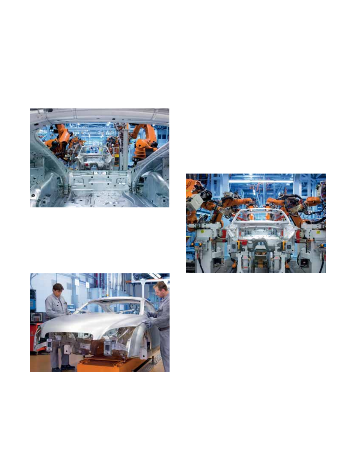
The original Audi TT, named after the legendary
“Tourist Trophy” race in the United Kingdom,
was a milestone in automotive design. The
design followed pure geometry, with the central
theme being a circle refl ected in the wheel
arches, roofl ine arches, and both the front and
rear fascias of the vehicle.
TT_BodyShop_1
The Audi TT RS, developed by quattro GmbH,
breathes new life into old traditions. Thanks to
a turbocharged 2.5-liter fi ve cylinder engine,
permanent all-wheel drive, and a sporty yet
comfortable suspension and design, both the
RS Coupe and RS Roadster are uncompromising
sports cars.
The production of the Audi TT RS involves the
use of two factories. The Audi Space Frame (ASF)
body is constructed in Ingolstadt, Germany,
while fi nal assembly is completed in Györ,
Hungary.
TT_BodyShop_3
TT_BodyShop_2
1
Page 6
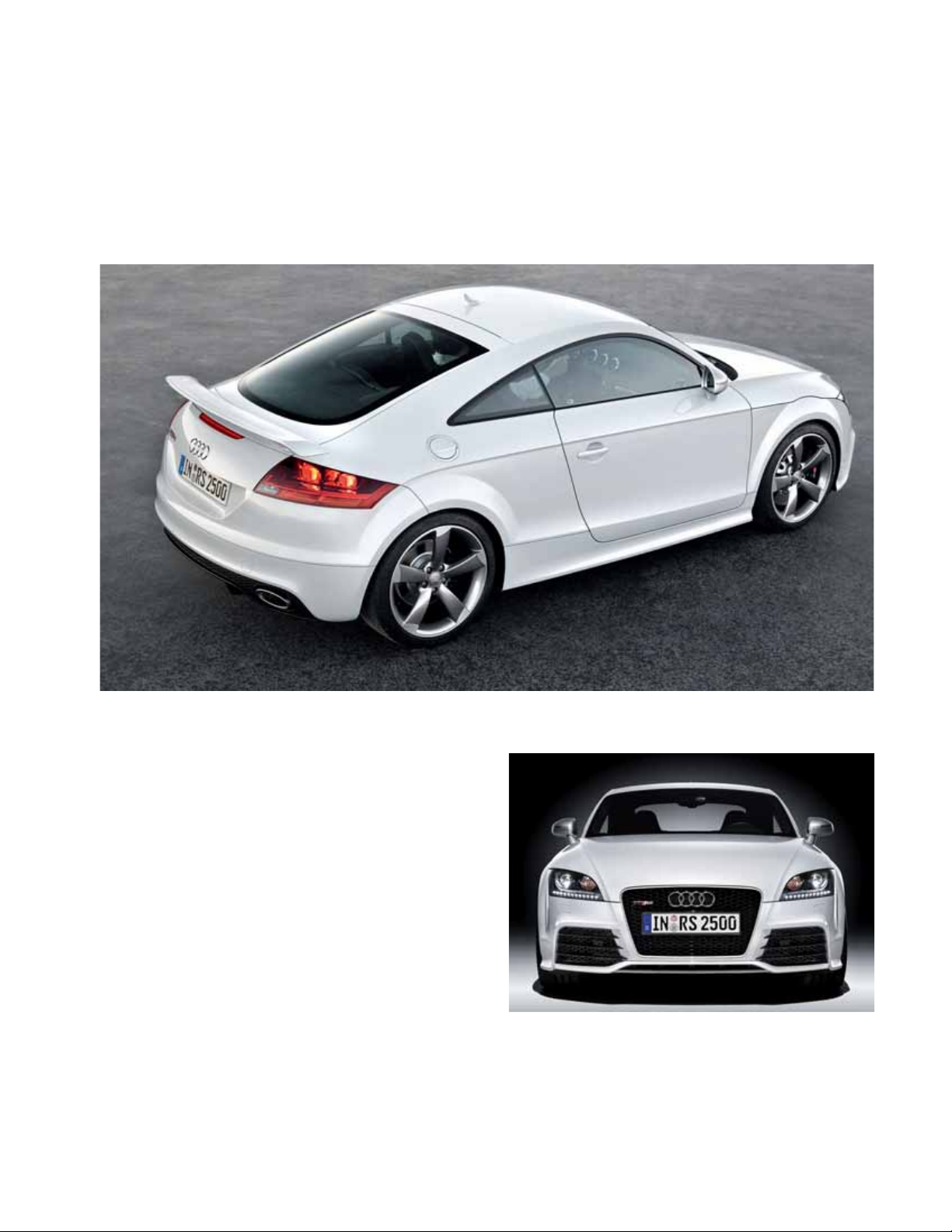
The TT RS is clearly the fl agship of the TT
model series. The muscular sheet metal body,
tautly curved surfaces, and sharp lines give an
impression of sculpture in motion.
From the side, the 18-inch wheels, large brakes,
and fl ared wheel openings of the TT RS instantly
catch the eye. Matte aluminum door mirror
covers are standard.
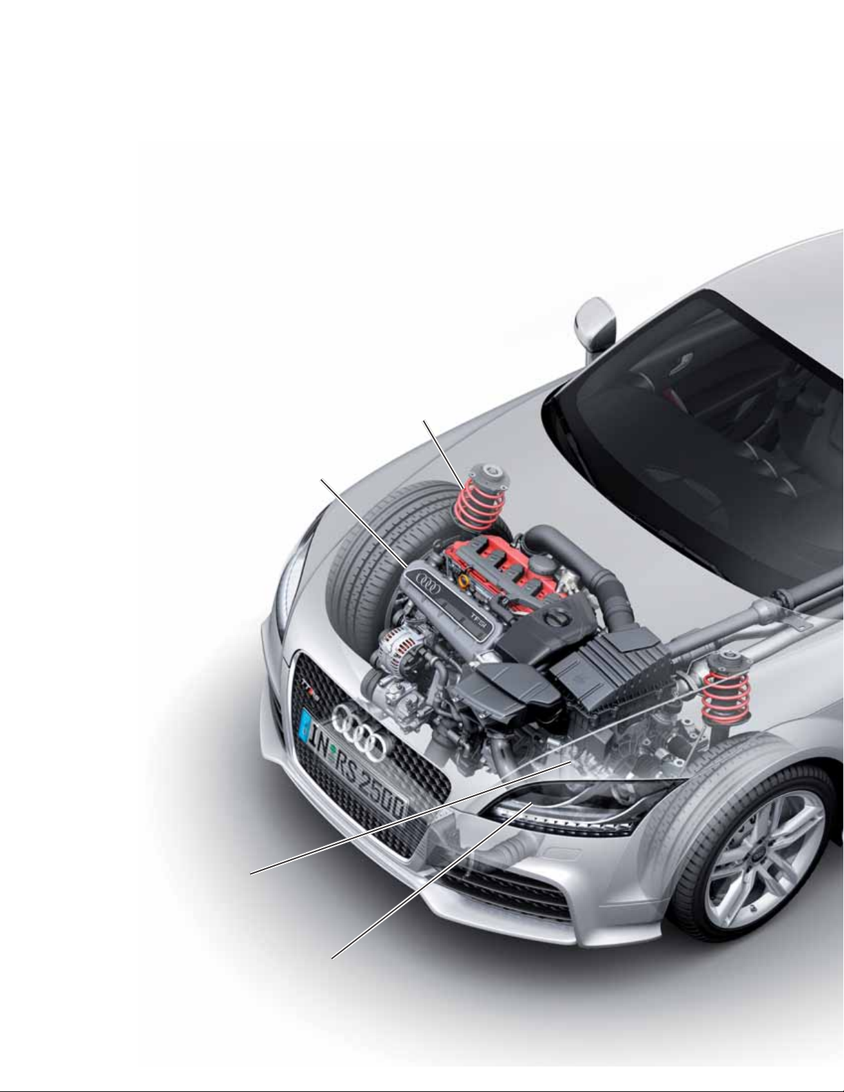
The front of the TT RS features the Audi marque
single frame grille. The insert is shiny black
bounded with a matte aluminum fi nish. Large
side air intakes with fl ared edges draw air into
the engine compartment.
The left intake routes air to the transmission,
while the right intake routes air to an auxiliary
radiator. The turbocharger draws in air through
the upper section of the grille while the
intercooler sits behind the lower segment of the
grille.
The front valance has been designed as a
splitter, and when coupled with the rear spoiler,
provides perfect aerodynamic balance.
451_011a
451_012
2
Page 7

The headlight design is a distinguishing Audi
characteristic. Xenon plus headlights, standard
on the TT RS, are accentuated by daytime
running lights comprised of 12 LEDs arranged in
a straight line.
451_013
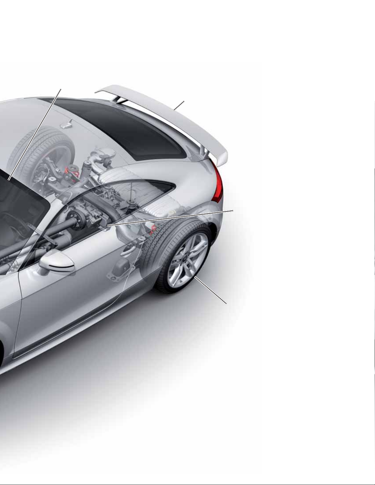
Rear View
The rear bumper includes an integrated diffuser
insert that surrounds two large, oval tailpipes.
A wide, stationary spoiler increases downforce
on the rear axle, improving stability at high
speeds. The automatic spoiler featured on the
standard production TT is available on the TT RS
as an option.
451_014a
451_015
3
Page 8
(10 mm lower than standard Audi TT)
2.5L TFSI engine with 335 hp
(250 kW) peak output
Sport suspension
ESP Sport Mode
Six-speed manual transmission
(0A6) with all-wheel drive
4
Xenon plus headlights
with LED DRLs
Page 9
Heated sports seats trimmed
with leather / Alcantara
Optional rigid spoiler (adjustable
rear spoiler as found on the
standard TT is also available)
generation all-wheel drive clutch
Rear wheel drive via the 4th
451_008
18 inch alloy wheels
with 245/40 tires
5
Page 10
Body
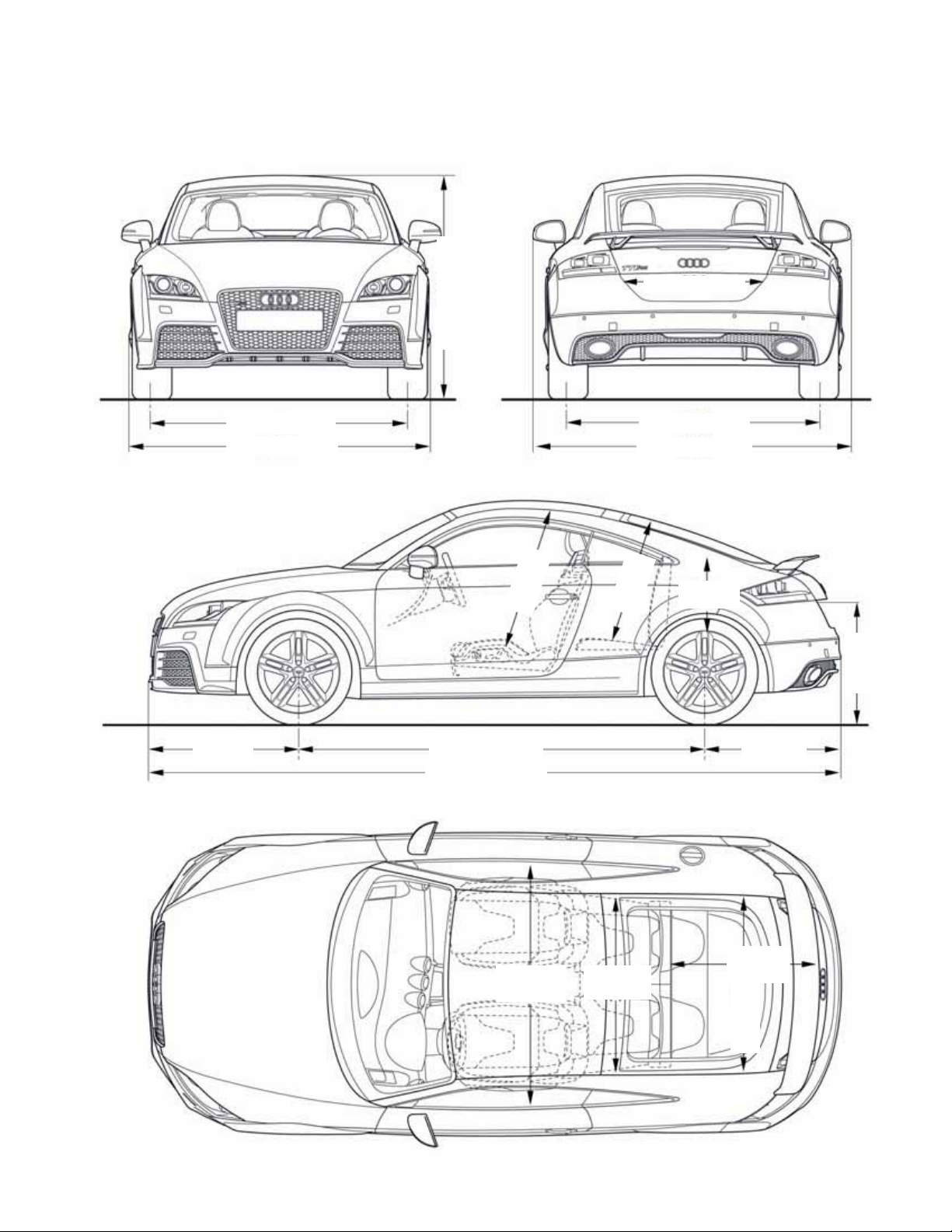
Dimensions
Audi TT RS Coupe
35.4 in (900 mm)
52.8 in (1342 mm)
61.2 in (1555 mm)
72.5 in (1842 mm)
35.8 in
(911 mm)
38.9 in
97.1 in (2468 mm)
165.2 in (4198 mm)
(990 mm)
60.8 in (1546 mm)
76.8 in (1952 mm)
32.6 in
(829 mm)
15.3 in
(390 mm)
32.4 in
(819 mm)
30.5 in
(777 mm)
32.1 in
60.3 in
(1532 mm)
6
47.4 in
(1532 mm)
(816 mm)
39.3 in
(1000 mm)
451_009
Page 11
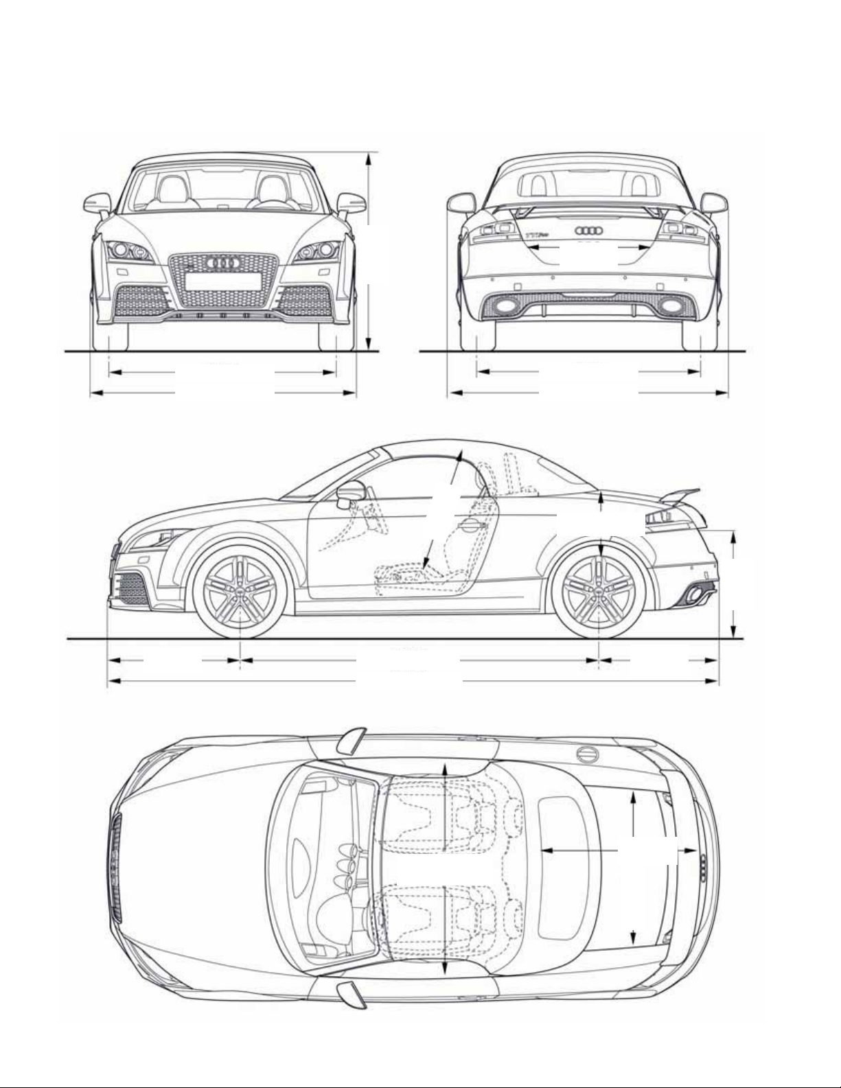
Audi TT RS Roadster
53.0 in
(1348 mm)
33.7 in
(856 mm)
61.2 in (1555 mm)
72.5 in (1842 mm)
35.8 in
(911 mm)
38.9 in
(990 mm)
97.1 in (2468 mm)
165.2 in (4198 mm)
60.8 in (1546 mm)
76.8 in (1952 mm)
9.6 in (245 mm)
32.2 in
(819 mm)
30.6 in
(778 mm)
53.2 in (1352 mm)
39.4 in
(1001 mm)
39.3 in
(1000 mm)
451_010
7
Page 12

Coupe Roadster
Curb weight
Maximum gross weight
Luggage capacity (seats folded down)
Fuel tank capacity
Drag coeffi cient
3196.6 lb (1450 kg)
4034.4 lb (1830 kg)
10.2 cu ft / 24.7 cu ft
(290 liter / 700 liter)
15.8 gal (60 liter)
0.32
3328.9 lb (1510 kg)
4034.4 lb (1830 kg)
8.8 cu ft (250 liter)
15.8 gal (60 liter)
0.34
8
Page 13

Notes
9
Page 14
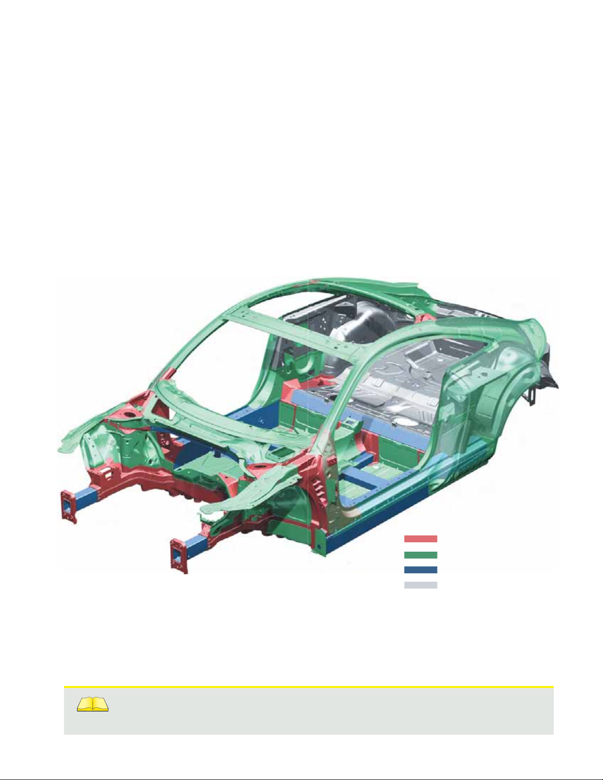
Audi Space Frame
Technical Design
The hybrid Audi Space Frame (ASF) fi rst used in
the 2008 TT is also used in the TT RS Coupe and
TT RS Roadster.
Sheet steel and aluminum sheet metal
components, aluminum castings, and aluminum
extruded sections form the TT RS body structure.
Vehicle weight distribution is optimized by
using sheet steel components in the rear facia,
improving driving dynamics and acceleration.
TT RS Coupe
Reference
For more information about the Audi Space Frame used in the Audi TT Coupe,
refer to Self-Study Program 994703, The 2008 Audi TT Body.
383_003
Aluminum castings
Sheet aluminum components
Aluminum extruded sections
Sheet steel components
10
Page 15
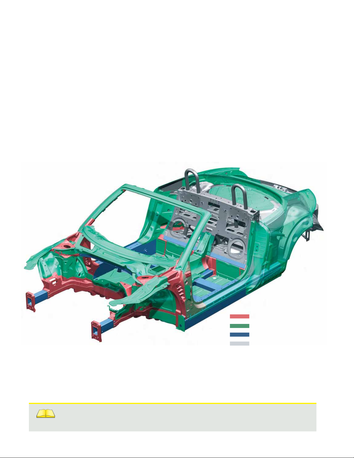
This ASF hybrid design guarantees maximum
rigidity and a balanced distribution of axle loads.
The body shell of the Coupe weighs 454.1 lb
(206 kg), while the body of the Roadster weighs
in at 553.3 lb (251 kg). Roadster weight is slightly
higher due to extra reinforcement.
TT RS Roadster
Reference
For more information about the Audi Space Frame used in the Audi TT Roadster,
refer to Self-Study Program 995703, The 2008 Audi TT Roadster.
391_039
Aluminum castings
Sheet aluminum components
Aluminum extruded sections
Sheet steel components
11
Page 16

2.5L TFSI Engine
Introduction
Audi’s fi ve-cylinder engines of the 1980s were
powerful, sporty engines that reinforced the
brand’s “Vorsprung durch Technik” commitment.
These fi ve-cylinder engines combined the
effi ciency of a four-cylinder with the power of
a six-cylinder, resulting in lighter and more
compact engine packages. A turbocharged
version was a sensation.
451_020
12
Page 17

Specifi cations
402.3 hp (300 kW)
362.0 hp (270 kW)
321.8 hp (240 kW)
Power in hp (kW)
Torque in lb ft (Nm)
281.6 hp (210 kW)
241.3 hp (180 kW)
201.1 hp (150 kW)
160.9 hp (120 kW)
80.4 hp (60 kW)
40.2 hp (30 kW)
Engine Code CEPA
Engine type
Five-cylinder inline engine
hp (kW)
442.5 lb ft (600 Nm)
398.2 lb ft (540 Nm)
354.0 lb ft (480 Nm)
309.7 lb ft (420 Nm)
265.5 lb ft (360 Nm)
221.2 lb ft (300 Nm)
177.0 lb ft (240 Nm)
lb ft (Nm)
88.5 lb ft (120 Nm)
44.2 lb ft (60 Nm)
0
2000 4000 5000 70001000 3000 6000
451_005
Displacement
Maximum power
Maximum torque
Valves per cylinder
Bore
Stroke
Compression ratio
Firing order
Fuel system
Fuel grade
Engine weight
Engine management
Exhaust emission standard
151.3 cu in (2480 cc)
335.2 hp (250 kW) @ 5400–6500 rpm
331.9 lb ft (450 Nm) @ 1600–5300 rpm
4
3.24 in (82.5 mm)
3.65 in (92.8 mm)
10 : 1
1-2-4-5-3
FSI (homogeneous) direct injection with demand-based high and low
fuel pressure regulation
Engine management without an air mass meter
91 AKI
403.4 lb (183 kg)
Bosch MED 9.1.2
LEV II
Emissions control
Sensors upstream and downstream of the catalytic converter
13
Page 18

Cylinder Block
Because of its very short overall length, this
engine lends itself very well to transverse
mounting.
451_025
19.4 in (494 mm)
20.07 in (510 mm)
22.04 in (560 mm)
23.1 in (589 mm)
23.2 in (591 mm)
451_026
14
Page 19

Material Selection
The cylinder block is made from high tensile
strength cast iron. The strength of this material
is needed because the connecting rod bearings
and main bearings have relatively small widths.
Cylinder block
Front sealing fl ange
Piston cooling jets are mounted in the cylinder
block.
Lower timing
case cover
Oil Level Thermal Sensor G266
Oil drain plug
Sheet steel
lower oil pan
Oil Pan
The oil pan is constructed from two parts. The
cast upper part acts as a baffl e plate and is
bolted to the crankcase. This upper part supports
the oil pump, which is bolted to the cylinder
block.
Cast upper oil pan
Check valve in the oil return line of the
positive crankcase ventilation system
451_037
The lower part of the oil pan is made from sheet
steel. It houses Oil Level Thermal Sensor G266
and the drain plug.
Both the front sealing fl ange and lower timing
case cover are sealed against the cylinder block
by a liquid sealant.
!
Note
The liquid sealants using during engine assembly and repair are specifi cally designated for various
components. Always check the latest technical literature and ETKA for correct application and
part numbers.
15
Page 20

Crankshaft Drive
The forged steel crankshaft is supported by six
main bearings.
Circlip
Connecting
rod bushing
Connecting rod
Piston
Wrist pin
A torsional vibration damper reduces radial
vibration by the pistons and crankshaft. The
damper, referred to as a viscodamper in repair
literature, uses a high viscosity silicone.
Crankshaft
Connecting rod
bearing shell
Connecting rod
bearing cap
Specifi cations
Center-to-center distance between cylinders
Block height
Connecting rod length
Crankshaft main bearings
Main bearing diameter
Connecting rod bearing diameter
451_027
3.46 in (88 mm)
8.66 in (220 mm)
5.66 in (144 mm)
6
2.28 in (58 mm)
188 in (47.8 mm)
16
Page 21

Pistons and Connecting Rods
To better respond to high loads, the pistons are
a “boxed” design. They have an asymmetrical
skirt with beveled box walls on the thrust and
counter-thrust sides. They are manufactured
from a high heat resistant alloy and have castin ring lands for the upper piston ring. Lower
weight and low oil consumption characteristics
were designed into these pistons.
N3, DSF** ring with
451_029
Mini headland rings
N1, asymmetrical, spherical,
N2, taper-face piston ring
tapered lands
steel nitride + PVD*
*PVD = Physical Vapor Deposition is a coating process in which
the coating material is physically vapor-deposited (by kinetic
or impact energy) on a material in a vacuum environment.
* *Top-beveled oil control ring with coil expander
451_027a
Optimized design with
large cross section
Reinforced
threads
M9 bolt
451_028
17
Page 22

Cylinder Head
The cylinder head is from the 2.5L 5-cylinder VW
engine, but to withstand the higher stresses of a
turbocharged engine, it was necessary to make
the following modifi cations:
– Different aluminum casting alloy
– Lower-set water jacket around the spark plug
– Tempered exhaust valve seats
– Attachment of a high-pressure pump to the
ladder frame
High-pressure
fuel pump
– Optimized exhaust cam contour
– Addition of an exhaust cam adjuster
– Sodium-fi lled exhaust valves for cooling
– Turbo-specifi c intake port (to produce the
required tumble air fl ow in the combustion
chamber)
Cam cover
Upper timing
case cover
Specifi cations
Intake valve diameter
Exhaust valve diameter
Intake valve lift
Exhaust valve lift
Intake camshaft adjustment range crank angle
Exhaust camshaft adjustment range crank angle
Cylinder head
Cylinder head gasket
451_006
1.33 in (33.85 mm)
1.10 in (28 mm)
0.42 in (10.7 mm)
0.39 in (10 mm)
42°
42°
18
Page 23

Chain Drive
The camshaft gears are located on the
transmission side of the engine. The drive
system is a two-stage arrangement using two
different chain types.
In the fi rst stage of the chain drive, the oil
pump and primary drive gear are driven by the
crankshaft. Attached to the primary drive gear
is the idler gear, which serves two purposes. It
drives both camshafts via the second chain, and
also provides a drive lug for operation of the
external vacuum pump.
A 3/8” gear chain is used in the primary drive
train to drive the oil pump and idler gear. It is
similar in design to the chain in the 2.0L R4 TFSI
engine and offers acoustic advantages over a
roller chain. A 3/8” roller chain is used in the
secondary drive.
The entire chain drive is lubricated by the oil
returning from both camshaft adjusters and by
a bore in the high pressure chamber of the chain
tensioner in the secondary drive. There is no
replacement interval for the chain drive.
Chain tensioner
Exhaust camshaft
adjuster
Intake camshaft
adjuster
Idler gear with lug for
driving vacuum pump
Primary
drive chain
Oil pump
sprocket
451_030
Tensioning rail
Secondary
drive chain
Tensioning rail
!
Note
Always replace timing case cover seals after performing work on the chain drive.
Refer to current technical literature for specifi cations.
19
Page 24

Oil Supply
High longitudinal and transverse acceleration
forces are to be expected when driving a
sport vehicle of this type. Because of this, the
engine lubrication system has been designed
to function reliably even in extreme driving
conditions.
The initial oil fi ll capacity of approximately 7.3 qt
(7.0 liter) is relatively high. In addition, the oil
pump intake is designed and installed to protect
against air induction under high longitudinal and
transverse acceleration forces.
Exhaust Camshaft
Adjustment Valve 1 N318
Oil Circulation System
A self-regulating oil pump circulates unfi ltered
oil from the oil pan through the oil fi lter module
and then through the oil cooler. The fi ltered oil
fl ows through passages to the lubrication points.
The oil cooler and fi lter are housed in a single
module mounted to the cylinder block. Oil check
valves for the cylinder block and cylinder head,
as well as an oil cooler bypass valve, are also
integrated into the module.
Camshaft Adjustment
Valve 1 N205
Filtered oil
Unfi ltered oil
Oil cooler
Turbocharger
Main oil
passage
Oil spray
jets
Bypass
Oil pump
451_032
Oil fi lter
module
Reference
For more details about the self-regulating engine pump, refer to Self-Study Program 922903,
The 2.0L 4V TFSI Engine with AVS.
20
Page 25

Crankcase Ventilation
The crankcase ventilation system of the 2.5L
TFSI engine is referred to as a “head ventilation”
system.
Single stage pressure
regulating valve
Fine oil
separator
Blow-by gases from the crankcase are directed
through riser channels integrated into the
cylinder block. The riser channels are protectively
located in the bearing saddle of main bearings
two, three, and four. The blow-by gases are
drawn into the camshaft cover through the
cylinder head, and are pre-cleaned as they pass
through the riser channels.
Oil return
Non-return
(check) valve
!
Blow-by gas
riser channels
Note
This sectional view does not show the positive crankcase ventilation (PCV) valve or the second
non-return (check) valve.
451_031
21
Page 26

The gas and oil spray mixture (blow-by) entering
the camshaft cover, fi rst fl ows into a relatively
large hollow chamber where oil droplets deposit
on the walls. The gas then fl ows to the fi ne oil
separator.
The fi ne oil separator consists of four
permanently open cyclone chambers and six
packets of up to nine cyclone chambers each
that can be activated or deactivated depending
on the blow-by gas fl ow rate.
Flow rate is dependent on engine speed, with
the cyclone chambers activated and deactivated
by locking springs with different spring
characteristics.
The separated oil from the camshaft cover and
fi ne oil separator is continuously recirculated to
the oil pan via return passages in the cylinder
head and cylinder block. Returned oil enters the
oil pan below the engine oil level.
In the extreme event of icing or malfunction,
the positive crankcase ventilation (PCV) valve in
the camshaft cover prevents high pressure from
damaging the engine. To avoid drawing oil from
the oil pan into the air intake system, a second
non-return (check) valve installed in the upper
part of the oil pan closes.
Cleaned blow-by gases are directed through a
single stage pressure regulating valve.
Depending on pressure in the intake manifold,
the gases fl ow through a non-return (check)
valve into the intake manifold downstream of the
throttle valve or upstream of the turbocharger
turbine.
A single stage pressure regulating valve is
integrated into the camshaft cover. The nonreturn (check) valves to the intake manifold or
turbocharger side are optimized for pressure
differential. Together with the pressure
regulating valve, they produce the partial
vacuum in the crankcase.
Locking springs with
different spring rates
Fine Oil Separator
Cleaned
blow-by gas
Separated oil
Cyclone
chamber
451_035
Blow-by
gas inlet
Cyclone chamber packets
(9 chambers per pack)
22
Permanently open
swirl chambers
Page 27

The positive crankcase ventilation (PCV) system
is used to purge the crankcase with fresh air at
part throttle. The system helps to separate fuel
and water that collects in the engine oil during
the combustion process.
If fuel and water are allowed to remain in
the oil pan, they can ice up at low ambient
temperatures, damaging the crankcase
ventilation system and engine. By admitting
air gathered downstream of the air fi lter, the
fuel and water are channeled out through the
camshaft cover.
Dry fresh air fl ows through the chain shaft and
into the crankcase, absorbing moisture and fuel
along the way. This helps prolong the useful life
of the lubricating oil.
The fresh air for crankcase ventilation is
extracted from the positive crankcase ventilation
line running to the exhaust turbocharger.
The PCV valve, which is integrated in the
camshaft cover, has the following tasks:
If a slight partial vacuum is present in the
crankcase during normal operation, it opens to
vent the crankcase. Fresh air fl ows from the line
downstream of the air fi lter and into the engine.
If a pressure of over 1.45 psi (100 mbar) develops
in the engine, excess pressure is relieved into
the line. This protects the crankcase seals.
A fault in the system or improper installation
of components are diagnosed by the ECM.
This is indicated to the driver via the MIL in the
instrument cluster.
Legend
A Throttle valve
B Camshaft
C Fine oil separator
D Pressure regulating valve
E Ladder frame
F PCV valve
G Diagnosis channel (closed)
H Turbocharger
I Intake manifold
J Cylinder head
K Cylinder block
L Extraction point in cylinder block
M Windage tray in upper oil pan
N Oil return line below oil level
O Oil pan
P Non-return (check) valves
!
451_040
Note
All components required for cleaning and ventilation are integrated in the cam cover. If one of these
components fails, the complete cam cover must be replaced.
23
Page 28

Cooling System
The cooling design is based on longitudinal
fl ow through cylinders 1 to 5. The coolant pump
is driven by a poly-vee belt and is designed to
control high thermal load, on the turbo engine.
To prevent the turbocharger from overheating
when the engine stops, the cooling system
is equipped with After-Run Coolant Pump
V51. When required, it is activated by ECM via
Auxiliary Engine Coolant Pump Relay J496.
451_007
Legend
A Breather pipe
B Expansion tank
C Heater heat exchanger
D Bleeder
E Exhaust turbocharger
F Coolant pump
G Coolant thermostat
24
H Engine oil cooler
I Engine Coolant Temperature Sensor G62
J Non-return (check) valve
K After-Run Coolant Pump V51
L Cooling Circuit Solenoid Valve N492
M Auxiliary cooler
N Cooler
Page 29

Air Supply
Fresh Air Intake
When designing the intake path, the primary
focus was on creating high effi ciency and
capacity.
air bypass line
Turbocharger intake line
with wastegate line
Turbocharger
Recirculating
The cross sections were optimally adapted to
available space, with air fl ow confi gured to be as
direct as possible.
Manifold Absolute Pressure Sensor G71
Intake Air Temperature Sensor G42
Air fi lter with
pulsation dampener
Cold air intake including
water separator
Intake manifold with
tumble fl ap system
Charge Air Pressure Sensor G31
Intake Air Temperature Sensor 2 G299
Throttle Valve Control
Module J338
Pressure tube upstream
of intercooler
Intercooler
The greatest pressure losses in a turbocharger
system occur at the intercooler.
The position of the intercooler at the lower front
of the vehicle allows maximum exposure to the
cooling air mass fl ow. This allows the fi ns of the
intercooler to be confi gured so that pressure
loss is reduced.
The total pressure loss along the air fl ow path
from the turbocharger outlet is only 1.9 psi
(135 mbar) at maximum fl ow.
451_034
Intercooler with
plastic shroud
451_069
25
Page 30

Intake Manifold with Flaps
The intake manifold is a two-part sand casting
comprised of the intake plenum and intake arm
gallery. A pneumatically actuated system of fl aps
is integrated in the intake gallery. Together with
the tumble intake port, this system produces
the turbulence necessary for optimum mixture
formation.
Intake manifold fl aps
Positive crankcase
ventilation system intake
Manifold Absolute Pressure Sensor G71
Intake Air Temperature Sensor G42
Air recirculation
channel
The fl ap position requested by the ECM is
measured by Intake Manifold Runner Position
Sensor G336. The ECM monitors this position.
When Intake Manifold Runner Control Valve N316
is not activated, the intake manifold fl aps are
completely closed.
Intake manifold,
upper part
Intake manifold,
lower part
Vacuum motor
Intake Manifold Runner
Position Sensor G336
Turbocharger
Recirculation Valve N249
Fuel rail
Injector
(six-hole)
Intake
manifold fl ap
451_038
Actuation of the intake
manifold fl ap shaft
26
Page 31

Exhaust System Overview
The exhaust system has the following
components:
– Turbocharger module
– Close-coupled pre-catalytic converter
– Twin-fl ow down pipes with isolating elements
– Two catalytic converters
– Two center muffl ers
– One rear muffl er with twin tailpipes
The exhaust turbocharger module is a derivative
of the four-cylinder TFSI engine. The illustration
below shows the separate connection between
the exhaust turbocharger and cylinder no. 3.
Compressor
intake manifold
!
Exhaust Gas Temperature
Sensor 1 G235
Separate cylinder connection
from exhaust turbocharger
Note
For the latest turbocharger mounting system, please refer to current technical literature.
451_036
27
Page 32

Turbocharger
The exhaust turbocharger, a type K16
turbocharger by Borg Warner Turbo Systems,
is notable for its high effi ciency over a wide
operating range.
It is large, with a compressor wheel that is
2.51 in (64 mm) in diameter at the outlet end.
At full throttle it can compress 10.24 cu ft
(7.0 liters) of air per second, producing relative
charge pressures of up to 17.4 psi (1.2 bar).
Heated Oxygen
Sensor G39
The exhaust turbocharger housing has a
separate oil supply, and is integrated with
the engine cooling circuit. When the engine
is switched OFF, After-Run Coolant Pump V51
dissipates the accumulated heat.
A sensor assisted exhaust gas temperature
regulation system ensures that a maximum
permissible exhaust gas temperature of 1796°F
(980°C) is not exceeded during operation.
To accomplish this, Exhaust Gas Temperature
Sensor G235 measures exhaust gas temperature
just before the turbine wheel.
Wastegate actuator
vacuum motor
Turbocharger Recirculation Valve N249
N249 is not located directly at the turbocharger
outlet. It is attached to the throttle valve body
upstream of the throttle valve.
The advantage of this design is that airfl ow is
not disturbed along the relatively long path to
the intake manifold via the intercooler. Turbine
speed losses are therefore minimized, which
results in the turbocharger therefore responding
very quickly after N249 is closed.
28
Wastegate Bypass
Regulator Valve N75
451_064
When N249 is opened, air is admitted into the
intake side of the turbocharger downstream
from the air fi lter via the air bypass.
Page 33

Exhaust System Components
To ensure compliance with LEV II exhaust
emission standards, it was necessary to position
the pre-catalytic converter as close as possible
to the turbocharger outlet, which is made of
ceramic material.
An oxygen sensor is integrated directly into
the turbocharger module at the outlet. Another
oxygen sensor is located directly downstream of
the pre-catalytic converter, and is non-linear.
Pre-catalyst
Isolating elements
Catalytic converters
Two additional catalytic converters are mounted
further downstream of the exhaust system.
A developmental goal for the dual fl ow
exhaust system was to minimize exhaust gas
backpressure, which resulted in large diameter
pipes being used.
Rear muffl er
Exhaust Flap
The left tailpipe has an exhaust fl ap. When this
fl ap is opened, the engine note becomes more
sporty. The fl ap is opened and closed by Exhaust
Door Valve 1 N321, which is characteristic mapcontrolled by the ECM.
If N321 fails, or there is a leak in the vacuum line
to the valve, the exhaust fl ap will stay open.
Center muffl er
451_071
451_052
Tailpipe
trims
29
Page 34

Belt Drive
Due to space limitations, the drive system for the
A/C compressor, alternator, and engine coolant
pump is a two-stage design.
A belt from the torsional vibration damper on the
crankshaft drives the A/C compressor, which has
twin belt pulleys.
Coolant pump
(track 2)
Crankshaft pulley
(track 1)
A second belt, driven by the A/C compressor,
drives the alternator, tensioner, and the engine
coolant pump.
Both belt tensioners are friction-damped. The
complete belt drive is designed for lifetime
operation.
Alternator
(track 2)
451_033
AC compressor
(tracks 1 and 2)
Alternator
(track 2)
Track 2
Track 1
AC compressor
(tracks 1 and 2)
451_065
30
Page 35

Fuel System
The TT RS fuel system is demand-controlled
on the high and low pressure sides. On the low
pressure side, the ECM regulates Fuel Pump
Control Module J538 and the delivery rate of the
fuel pump in the tank.
On the high pressure side, the ECM regulates
Fuel Metering Valve 290 directly at the highpressure pump. To monitor pressure levels in
the system, two fuel pressure sensors send their
respective signals to the ECM.
High-pressure
fuel pump
Low Fuel Pressure
Sensor G410
Fuel Metering
Valve N290
The central element of the fuel system is a
demand-controlled single-piston high-pressure
pump. This Generation III fuel pump by Hitachi
is driven by a three-lobe cam seated on the
exhaust camshaft.
The system operates at a maximum pressure of
1740.4 psi (120 bar). A pressure limiting valve in
the pump opens at a pressure of approximately
2103.0 psi (145 bar).
Fuel Pressure
Sensor G247
Fuel fi lter
To ECM
Fuel injectors 1–5
(N30–33 and N83)
Battery
positive
Fuel Pump Control
Module J538
Fuel Pump G6
451_003
!
Warning
Be very careful when working on the fuel system. It operates a extremely high pressures. To open the high
pressure side, always follow the instructions given in current technical literature.
31
Page 36

System Overview
Sensors
Charge Air Pressure Sensor G31
Intake Air Temperature Sensor 2 G299
Manifold Absolute Pressure Sensor G71
Intake Air Temperature Sensor G42
Engine Speed Sensor G28
Throttle Valve Control Module J338
EPC Throttle Drive Angle Sensor 1 G187
EPC Throttle Drive Angle Sensor 2 G188
Camshaft Position Sensor G40 (Intake)
Camshaft Position Sensor 3 (Exhaust)
Accelerator Pedal Position Sensor G79
Accelerator Pedal Position Sensor 2 G185
Clutch Position Sensor G476
Powertrain CAN data bus
Brake Light Switch F
Brake Pedal Switch F47
Sport Program Button E541
Fuel Pressure Sensor G247
Low Fuel Pressure Sensor G410
Knock Sensor 1 G61
Knock Sensor 2 G66
Oil Pressure Switch F22
Engine Coolant Temperature Sensor G62
Intake Manifold Runner Position
Sensor G336
Engine Control
Module J623
Data Link
Connector
Heated Oxygen Sensor G39
Oxygen Sensor After Three Way
Catalytic Converter G130
Exhaust Gas Temperature Sensor 1 G235
Auxiliary signals:
– J393 Door Contact Signal
32
– E45 Cruise Control System (ON/OFF)
Page 37

Actuators
Fuel Pump Control Module J538
Transfer Fuel Pump G6
Injectors for Cylinders 1–5
(N30–33 and N83)
Ignition Coils for Cylinders 1–5
(N70, N127, N291, N292, N323)
Throttle Valve Control Module J338
EPC Throttle Drive G186
Intake Manifold Runner Control
Valve N316
Engine Component Power Supply
Relay J757
Motronic Engine Control Module
Power Supply Relay J271
Wastegate Bypass Regulator Valve N75
EVAP Canister Purge Regulator Valve 1
Turbocharger Recirculation Valve N249
Fuel Metering Valve N290
Exhaust Door Valve 1 N321
Camshaft Adjustment Valve 1 N205
Exhaust Camshaft Adjustment Valve
1 N318
Coolant Circuit Solenoid Valve N492
Coolant Fan Control Module J293
Coolant Fan V7
Coolant Fan 2 V177
451_004
Oxygen Sensor Heaters Z19, Z29
Auxiliary Engine Coolant Pump
Relay J496
After-Run Coolant Pump Relay V51
33
Page 38

Engine Management
The Bosch MED 9.1.2 engine management
system calculates engine load from the
values of Manifold Absolute Pressure Sensor
G71 and Engine Speed Sensor G28. To meet
LEV II emission standards, the following
subassemblies, in combination with special
injection and catalytic converter heating
strategies, are used:
– Intake manifold with intake manifold fl aps
– Multi-port fuel injection and fl at pistons
– Close-coupled pre-catalytic converter
A secondary air injection system was not
needed.
Combustion Process
By optimizing spray parameters in combination
with a fl at piston crown shape, it was possible
to improve mixture formation compared to
the 2.0L TFSI engine, despite the approximate
25% increase in fl ow rate of the high-pressure
injectors.
Operating Modes
The following operating modes are possible:
– High pressure stratifi ed charging starting at
an ambient temperature of –14.8°F (–14.8°C)
– Catalytic converter heating and quicker engine
warm-up through double injection
– Camshaft timing and exhaust camshaft
duration adaptation to create high cylinder
scavenging rates, minimizing the amount of
residual gas in the cylinders when the engine
is warm and running at low rpm
– Matching of intake and exhaust pressures in
the upper rpm band to optimize fl ow rates and
minimize pressure losses
Flat-crown piston
451_053
Optimized tumble
intake port
Spray-optimized, six-hole,
high pressure injection
34
Page 39

Engine Load Sensing
Engine load is calculated from engine speed and
air mass values. Because no mass airfl ow sensor
is used, two identical combined temperature/
pressure sensors are used:
– Charge Air Pressure Sensor G31, Intake Air
Temperature Sensor 2 G299
– Manifold Absolute Pressure Sensor G71, Intake
Air Temperature Sensor G42
Two sensors are used because very different
pressures can exist simultaneously on either
side of the throttle valve assembly.
Also, the cast aluminum intake accumulates heat
and could potentially falsify the temperature
signal by temperature sensors G71/G42. The
temperature signal generated by G31/G299
upstream of the throttle valve is the most
reliable measurement.
Intake manifold
Throttle Valve Control
Module J338
Second Sensor
451_078
Charge Pressure Sensor G31,
Intake Air Temperature
Sensor 2 G299
First Sensor
Designation: Charge Pressure Sensor G31/Intake
Air Temperature Sensor G299
Task: Measurement of pressure and temperature
upstream of the throttle valve
This sensor is the boost pressure sensor and is
used to control boost pressure. Its signal is not
actually required at full open throttle because
boost pressure will be the same as pressure in
the intake manifold. However, in order to achieve
a better response, boost control (measured by
this sensor) becomes active even before the
throttle valve fully opens.
If the sensor fails, the charge pressure control
system will go into limp-home mode. This means
the engine will run as a normally aspirated
engine, with the MIL lighting up, and a DTC
stored in the ECM.
Intake Air Temperature
Sensor G42
Designation: Manifold Absolute Pressure Sensor
G71, Intake Air Temperature Sensor G42
Task: Measurement of pressure and temperature
in the intake manifold
This is referred to as the main charge sensor and
replaces the hot-fi lm air mass sensor. The air
mass fl owing through the engine is calculated at
all operating points of the engine from signals
generated by this sensor. The requisite amount
of fuel is then injected.
If this sensor fails, the engine will go into limphome mode, with engine power output reduced.
Air mass is then calculated in “alpha n mode,”
which is based on the throttle valve angle and
engine speed only. The MIL will light up and a
DTC will be stored in the ECM.
451_077
35
Page 40

Sport Mode
The following functions can be activated with
the Sport button:
– Direct accelerator response. A different
characteristic curve is selected by the engine
control module
– Modifi cation of exhaust system
characteristics. Vacuum motor for the exhaust
fl ap door is actuated by Exhaust Door Valve 1
– Sport driving mode of Audi magnetic ride is
activated
– Sport program indicator lamp K91 illuminates
Automatic Transmission Sport
Mode Indicator Lamp K91
451_045
Legend
E461 Front Center Console Control Head
E541 Sport Program Button
G76 Left Rear Level Control System Sensor
G77 Right Rear Level Control System Sensor
G78 Left Front Level Control System Sensor
G79 Accelerator Pedal Position Sensor
G185 Accelerator Pedal Position Sensor 2
G289 Right Front Level Control System Sensor
J250 Electronic Damping Control Module
36
J623 Electronic Control Module
K91 Automatic transmission Sport Mode Indicator Lamp
L156 Switch Illumination Bulb
N321 Exhaust Door Valve 1
N336 Left Front Damping Adjustment Valve
N337 Right Front Damping Adjustment Valve
N338 Left Rear Damping Adjustment Valve
N339 Right Rear Damping Adjustment Valve
S Fuses
Page 41

Manual Transmission 0A6
Manual Transmission 0A6 with all-wheel drive
Ratio including front axle drive i
Ratio spread
Front axle drive ratio
Weight with oil fi ll
Six-speed manual transmission 06A can handle up to 368.7 lb ft (500 Nm) of torque.
total
1st gear
2nd gear
3rd gear
4th gear
5th gear
6th gear
Reverse gear
1st – 6th gear
Output shaft – 1st/2nd gear
Output shaft – 3rd – 6th gear
Output shaft – reverse gear
13.45
8.12
5.51
4.16
3.36
2.83
14.41
4.75
64 : 17 = 3.765
64 : 22 = 2.09
64 : 20 = 3.200
187.3 lb (85 kg)
37
Page 42

Notes
38
Page 43

Drive Concept
The TT RS has the quattro permanent all-wheel
drive system as standard equipment. No frontwheel drive version is offered.
Running Gear
06A six-speed
transmission
Front axle
differential
Engine
Bevel gear
Prop shaft
Rear axle
differential
Generation IV all-
wheel drive clutch
Rear axle drive
451_001
39
Page 44

Generation IV All-Wheel Drive Clutch
The TT RS powertrain uses the Generation IV allwheel drive clutch. Power is transmitted via the
clutch plate set in the same way as the previous
Haldex generations. The major difference is that
clutch hydraulic pressure build-up is performed
by an electric pump on the Generation IV system.
All Wheel Drive Control Module J492 determines
torque to be transferred by controlling Haldex
Clutch Control Valve N373. Speed differences
between the front and rear axle are no longer
required to activate the all-wheel drive coupling.
Rear axle differential
drive pinion
Thanks to a high performance pressure
reservoir, all of this happens within a matter of
milliseconds.
To optimize TT RS axle load distribution, the
Generation IV clutch is mounted in front of the
rear axle differential.
Crown gear
All-wheel drive clutch
plate assembly
Drive shaft
All Wheel Drive
Control Module J492
All-wheel drive
clutch oil reservoir
451_063
Rear axle
differential
40
Page 45

451_048
Front Axle
The front suspension system, with a track width
of 61.06 in (1551 mm) is a MacPherson-type
design with triangular lower wishbones. The
pivot bearings, subframe, and wishbones are
made from aluminum. To increase rigidity, the
subframe is bolted to the body at six points.
Steering
The electromechanical power rack-and-pinion
steering system comes with variable servo
assistance. Its characteristics have been adapted
to the dynamic qualities of the TT RS.
Rear Axle
The four-link rear axle, with a track width of
60.8 in (1546 mm), is capable of absorbing
longitudinal and lateral forces separately thanks
to its sophisticated design.
The longitudinal links absorb the driveline and
braking forces, while the relatively soft mounts
permit excellent ride comfort.
The three links per wheel — the spring link, the
upper wishbone, and tie rod — are attached
rigidly to the subframe to enhance handling
dynamics.
The elastokinematic behavior of the high
strength steel control arms has been modifi ed
compared to non-RS TT models. Separate coil
springs and newly developed dampers provide
vertical support.
The body of the TT RS has also been lowered
0.39 in (10 mm) compared to non-RS TT models.
41
Page 46

Audi Magnetic Ride
Audi magnetic ride is offered as standard
equipment on the 2012 TT RS.
Function
Circulating inside its damper pistons is a
synthetic hydrocarbon fl uid containing minute
magnetic particles between three and 10
micrometers in size. When voltage is applied to
a coil, a magnetic fi eld is created in which the
orientation of particles changes.
Magneto-rheological fl uid
in a non-magnetized state
Magnetic particles
Piston orifi ces
These magnetic particles cluster transversely
to the direction of fl ow of fl uid, thus inhibiting
fl ow through the piston channels. This alters
the damping characteristic within a matter of
milliseconds.
Magneto-rheological fl uid
in a magnetized state
Magnetic fi eld
451_050
Magnetic coil not activated Magnetic coil activated
Operation
The system’s control module constantly
monitors the driver’s style and condition of the
road, adjusting its response accordingly. The
driver can change between Normal and Sport
modes at the touch of a button. In Normal mode,
when the fl uid has high viscosity, the suspension
of the Audi TT RS offers a well-balanced,
comfortable ride.
Reference
For further information about the Audi Magnetic Ride system, refer to Self-Study Program 993703,
The 2008 Audi TT Running Gear.
42
451_049
In Sport mode, when fl ow is inhibited, the
suspension is uncompromisingly fi rm, so the
car hugs the road with minimal body roll. The
specifi c stabilization of each wheel offers more
neutral self-steering behavior, resulting in a
more precise steering response.
Page 47

Brake System
All four wheels feature ventilated disc brakes.
The front brake discs are 14.5 in (370 mm) while
the rear discs are 12.2 in (310 mm). The front disc
friction surfaces are cross-drilled to promote
maximum heat dissipation.
Aluminum hub
Ventilated and
drilled brake discs
Electronic Stabilization Program
(ESP)
All four calipers are manufactured from
aluminum to reduce unsprung weight. The front
calipers are painted black and sport the RS logo.
Front Brake
Four-piston
brake caliper
451_047
The Electronic Stabilization Program is optimized
for dynamic driving but can be deactivated in
two stages using ASR/ESP Button E256 in the
center console.
First Stage (Sport Mode)
In the fi rst stage (Sport mode), traction control
is disabled and the brakes intervene somewhat
later than in normal operation. To select, push
the ESP OFF button briefl y. The ESP warning
light in the instrument cluster comes ON and
ESP Sport is displayed in the Driver Information
System. Driving stability is limited in Sport
mode.
Second Stage (complete shut down)
In the second stage, ESP is completely
deactivated. To select, push the ESP OFF button
for longer than three seconds. The ESP warning
lamp comes ON and ESP OFF is displayed in
the Driver Information System. When ESP is
deactivated, traction control is also deactivated.
451_046
TCS/ESP button
!
Note
ESP Sport mode should only be activated for agile handling and sporty driving if road,
weather, visibility, and traffi c conditions permit.
43
Page 48

Service
New Special Tools for the TT RS
T03000 Engine support
451_054
For removing and installing the engine in combination with
the engine and transmission support V.A.G. 1383 A
T03001 Engine support
451_055
For mounting the engine on the engine and transmission
support VAS 6095 or support clamp VW313
T03003 Wrench
T03004 Assembly sleeve
451_057
For setting the crankshaft to TDC
44
451_056
For replacing the crankshaft sealing fl ange on the belt pulley
side
Page 49

T03005 A Oil pump clamp
T03006 Locking pin
451_059
451_058
Oil pump clamp
T40057 Oil drain adapter
For draining engine oil out of the oil fi lter module
Chain tensioner clamp
T40226 Gauge
451_060
451_061
For transmission mounting
45
Page 50

Self-Study Programs for the Audi TT
SSP 991703 The 2008 Audi TT
Introduction
– Body
– Occupant Protection
– Engine
– Suspension System
– Electrical System
– Climate Control
– Infotainment
SSP 992703 The 2008 Audi TT
Electrical and Infotainment Systems
– Control Module Locations
– Topology and Networking
– Electrical and Comfort System Electronics
SSP 993703 The 2008 Audi TT
Running Gear
Service Training
The 2008 Audi TT
Vehicle Introduction
Self-Study Program 991703
Service Training
The 2008 Audi TT
Electrical and Infotainment Systems
Self-Study Program 992703
Service Training
– Axles
– Brake System
– Steering System
– Audi Magnetic Ride
– Other Features
SSP 994703 The 2008 Audi TT
Body
– Audi Space Frame (ASF)
– Joining Techniques and Production Processes
– Vehicle Safety Concept
– Dimensions
The 2008 Audi TT
Running Gear
Self-Study Program 993703
Service Training
The 2008 Audi TT Body
Self-Study Program 994703
46
Page 51

Knowledge Assessment
An on-line Knowledge Assessment (exam) is available for this Self-Study Program.
The Knowledge Assessment is required for Certifi cation.
You can fi nd this Knowledge Assessment at:
www.accessaudi.com
From the accessaudi.com Homepage:
– Click on the “ACADEMY” tab
– Click on the “Academy Site” link
– Click on the “CRC/Certifi cation” link
– Click on Course Catalog and select “990713 — Audi TT RS with the 2.5l TFSI Engine”
For assistance please call:
Audi Academy
Certifi cation Resource Center (CRC)
1-877-283-4562
(8:00 a.m. to 8:00 p.m. EST)
Or you may send an email to:
audicrchelpdesk@touchstone-group.com
Thank you for reading this Self-Study Program and taking the assessment.
47
Page 52

990713
All rights reserved.
Technical specifi cations subject
to change without notice.
Audi of America, LLC
2200 Ferdinand Porsche Drive
Herndon, VA 20171
 Loading...