

Audi TT Coupé 207, TT Coupe Service
Service.
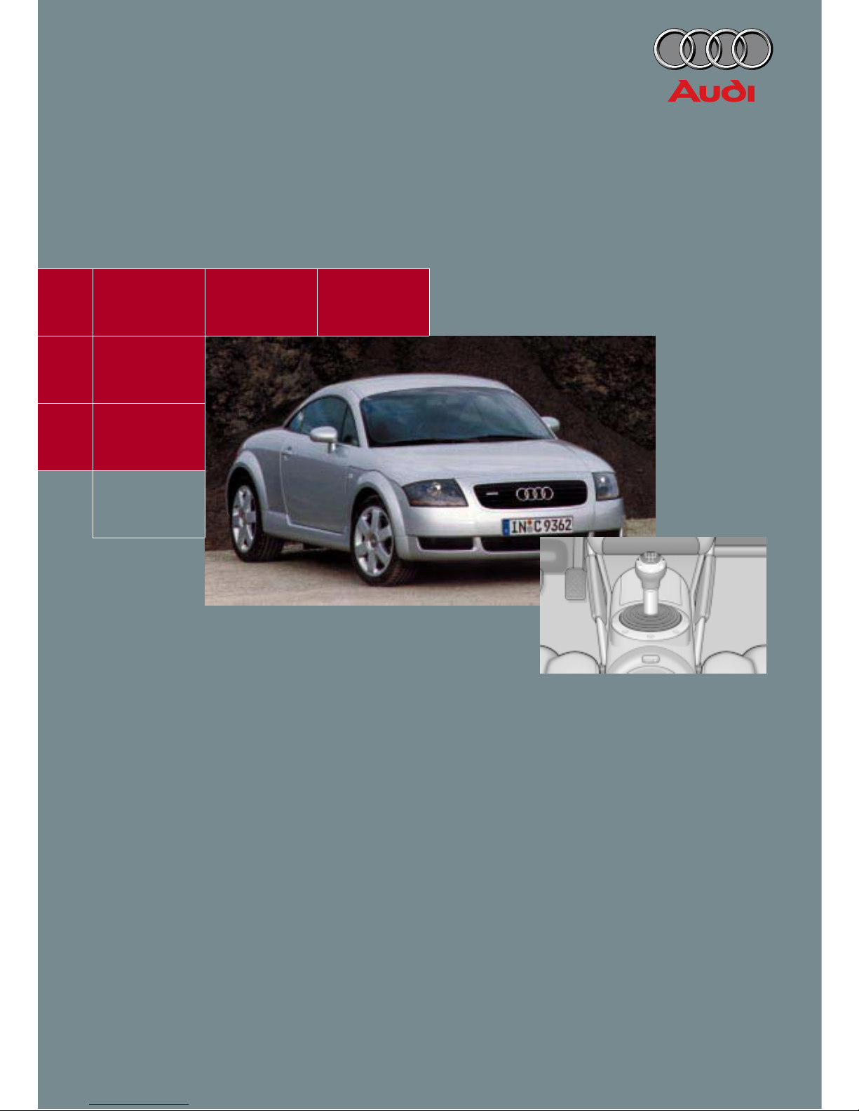
The Audi TT Coupé
Design and Function
Self-Study Programme 207
For internal use only.
2
Quality that is measurable
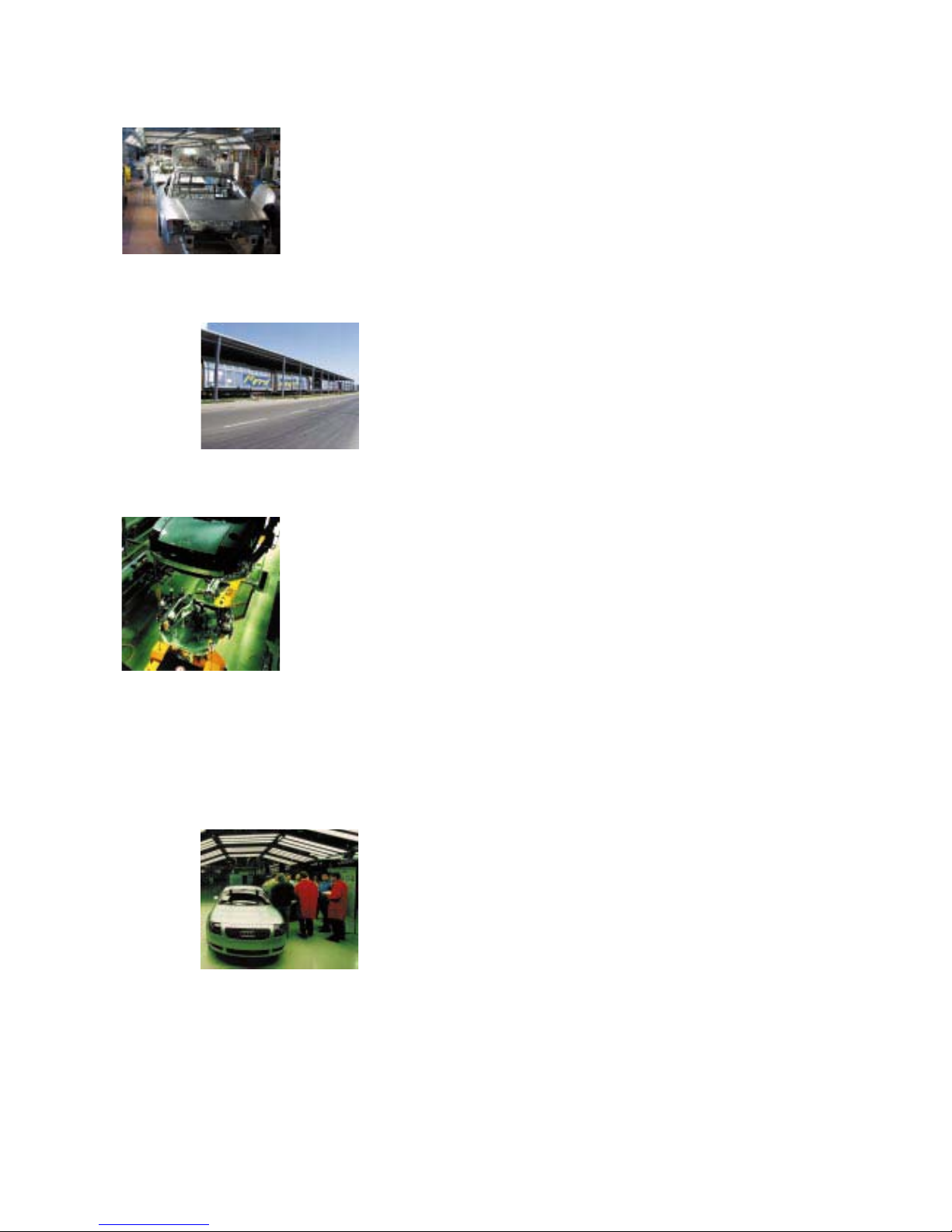
The plant – the plants
Ingolstadt plant
The model series Audi A4 and Audi A3 are produced in Ingolstadt.
A separate production line has been set up for the body in white of
the Audi TT Coupé.
The head office of Technical Development is also located in Ingolstadt.
Special trucks were developed for transferring the bodyshells to Györ for final assembly.
High-tech from Györ
Qualified specialists and a good infrastructure are key factors for the
Audi production shop in Györ.
Audi has been manufacturing four-cylinder 5V, V6 and V8 engines
here since 1997. Final assembly of the TT has also been taking place
here since 1998.
Axle and steering geometry measurement
Watertightness test
Electrical function test
Roller dynamometer
Exhaust emission test and optimal setup
Acoustic test bench
100% reliability is ensured through a series of systematic checks integrated in the production process.
Functional tests are an integral part of the production
process
Mounted parts are tested for accuracy of fit, build quality
and functionality after each stage of assembly.
After final assembly, extensive tests and adjustments
are carried out on every single Audi.

3
Power transmission . . . . . . . . . . . . . . . . . . . . . . . . . . 48
5-speed manual gearbox
6-speed manual gearbox
Haldex viscous coupling
Contents
A brief introduction to the TT . . . . . . . . . . . . . . . . . . . . 4
Body . . . . . . . . . . . . . . . . . . . . . . . . . . . . . . . . . . . . . . . . 9
Special features
Running gear . . . . . . . . . . . . . . . . . . . . . . . . . . . . . . . . 56
Steering
Front axle
Rear axle
Brake system
Design needs no explanation
Vehicle dimensions
Vehicle identification
Environmentally-friendly production
The Self-Study Programme is not a Workshop Manual.
The Self-Study Programme provides you with information
regarding design and function.
New. Important.
Note.
Vehicle safety . . . . . . . . . . . . . . . . . . . . . . . . . . . . . . . . 14
Occupant protection
Fuel cut-off
Drive units . . . . . . . . . . . . . . . . . . . . . . . . . . . . . . . . . . 18
Engine and gearbox combinations
1.8-ltr. 132 kW 5V turbocharged engine AJQ
1.8-ltr. 165 kW 5V turbocharged engine APX
Fuel system . . . . . . . . . . . . . . . . . . . . . . . . . . . . . . . . . 42
Electrics . . . . . . . . . . . . . . . . . . . . . . . . . . . . . . . . . . . . 64
Vehicle electrical system
Interior monitoring
Immobiliser
Sound system
Service . . . . . . . . . . . . . . . . . . . . . . . . . . . . . . . . . . . . . 84
Flexible service interval indicator
Oil level sensor
Specifications
Special tools
Heating/air conditioning system . . . . . . . . . . . . . . . . 76
Page
Please refer to the Service Literature for all the relevant
maintenance and repair instructions.
Overview
Expansion valve
Subsystems of the Motronic . . . . . . . . . . . . . . . . . . . 37
Lambda control in the EUIII
Torque-oriented engine management
Accelerator position sender
Electrically-activated throttle valve
4
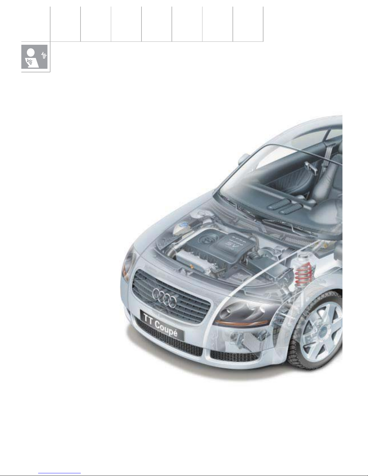
A brief introduction to the TT
Design needs no explanation
The name alone suggests that this is an Audi
with a difference. The Audi TT was named
after the legendary Tourist Trophy race on the
Isle of Man - the only one of its kind in the
world.
The Audi TT is equally as unique as its legendary namesake.
Engines
As befits a sports car, the Audi TT is
powered by a four-cylinder 5-valve
turbocharged engine developing
180 bhp with a sports gearbox in
the front-wheel drive and quattro
versions. A four-cylinder 5-valve
turbocharged engine
developing 225 bhp is
available for the
quattro version.
Running gear
The running gear also underscores Audi’s
total commitment to the sports car concept.
The front axle kinematics were revised with
regard to steering quality and response.
This, in combination with the Audi TT’s sporty,
stiff suspension tuning, ensures excellent
handling and a high standard of driving safety.
The interior styling matches the exterior perfectly - a fact reflected in the features of the
dash panel, the styling of the instruments, the
air nozzles and controls.
The styling of some parts has also been influenced by the use of aluminium.
The basic version is equipped with 16-inch
wheels shod with size 205/55 R 16 tyres.
A 17-inch suspension is standard with the
quattro and available as optional equipment
for all other engine variants.
5
There is no doubt that the real highlight of the
Audi TT is its emotive design, both on the
exterior and in the interior. The engineers at
Audi had an ambitious development goal: to
meet all functional and quality standards as
well as the latest statutory requirements and
Audi’s high standards of safety without compromising the design concept and while retaining the car’s full viability for everyday use.
Design
We at Audi firmly believe that the most
important thing about designing is that
actions speak louder than words. Suffice to
say, a good design speaks for itself.
The TT has a “wheel-hugging” design, that is
to say the entire body is styled around the
wheels. That also goes for the front and rear
bulges as well as the roof and window lines
and the low-slung passenger cabin.
Quattro power train
The TT will feature a new generation of Audi
technology and the new Haldex viscous coupling, further emphasising the vehicle’s sporty
character.
Safety
Safety is paramount:
That’s why the TT is equipped with front airbags for the driver and front passenger.
The TT already complies with the new European safety laws which will come into effect in
the year 2003 as well as the tougher requirements according to the US Head Impact Protection Act.
SSP207/1
6
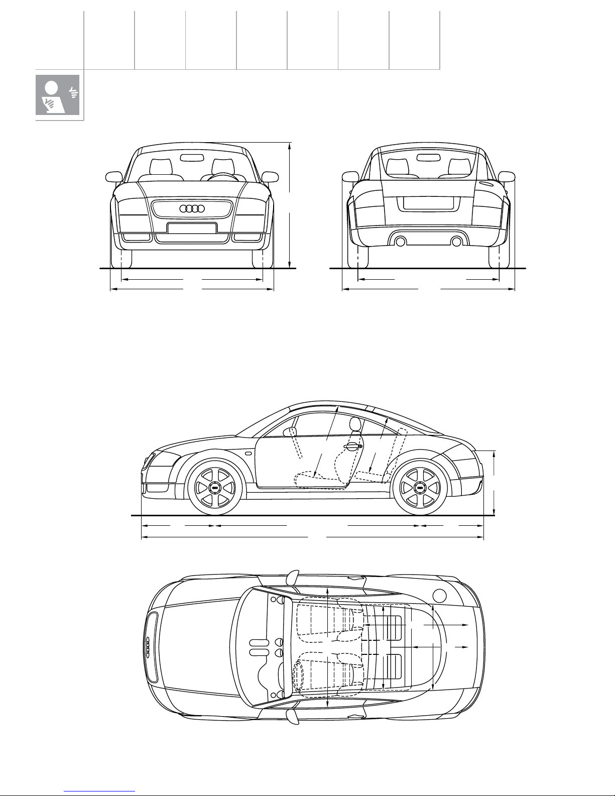
The “+ and –“ dimensions are reference values compared to the Audi A3
Length: –111 mm
Width: +45 mm
Height: –69 mm
Vehicle dimensions
A brief introduction to the TT
4041
7462419 (quattro 2427)
(quattro 738)
876
762
9
5
9
8
2
8
1525
1764
1354
1507 (quattro 1503)
1856
1412
1209
900
1221
950
Track width
Front: +12 mm
Rear: +12 mm
+ 8 mm quattro
Wheelbase: –93 mm
–85 mm quattro
7
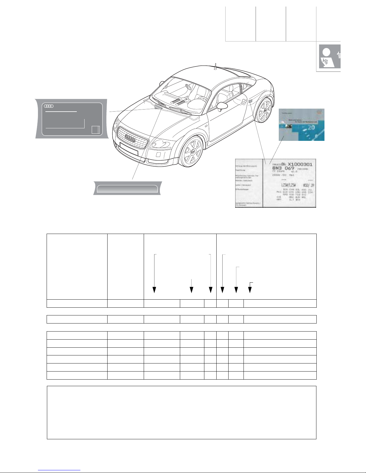
Vehicle identification
Key of manufacturing
plants within the Group
in digit position 11:
World manu-
facturing code
Part describing vehicle Part identifying vehicle
A Ingolstadt
N Neckarsulm
1 Györ
X Poznan
K Karmann/Rheine
Filler
constant = Z
Model year, alphanumeric as prescri-
bed by law
Digits 1 + 2 vehicle
class. acc. to structure table
Manufacturing plant within
the Group (as at 04/94)
Serial No. beginning
with:
1234567891011121314151617
Audi Hungaria Motor Kft:
TT/TTS *TRUZZZ8NZX 1 000001
Audi AG:
A3 *WAUZZZ8LZXA 000001
A4 *WAUZZZ8DZX A 000001
A6 (incl. SKD Poland) * W A U Z Z Z 4 B Z X N/X 000001
A8 *WAUZZZ4DZX N 000001
Cabrio *WAUZZZ8GZX K 000001
Audi 100 (C3, CKD) * W A U Z Z Z 4 4 Z X A 000001
* Vehicles to US specification
(USA, Canada, Saudi Arabia, tourists)
On the VIN (behind the windscreen), the certification label and on official documents, the fillers (Z) are replaced by a vehicle code (digits 4-8) or by a test mark (digit 9). This (18-digit) number is the official vehicle identification No. (VIN) in the countries listed above.
*
TRUZZZ8NZX1000301
*
AUDI HUNGARIA MOTOR KFT
TRUZZZ8NZX1000301
1765 kg
kg
1 - 1015 kg
2 - 850 kg
1
1000
2111008
Typ 8N

8
Environmentally-friendly
production
Environmental protection is firmly rooted in
Audi’s corporate strategy. During the vehicle
development process, all environmental criteria are incorporated into the product and production concept from the outset. Economic
goals and ecological needs are balanced so
that no conflicts of aims arise.
Waste avoidance and reduction
From 1998 onwards, Audi will use only watersoluble paints in a effort to make its production process more environmentally-friendly.
This step will see a dramatic reduction in solvent emissions. Today’s fillers and base coats,
for example, contain up to 45% solvent. By
comparison, the solvent content in water-soluble systems is only about 6%.
A brief introduction to the TT
Produce locally - think global:
Audi lays great store by waste avoidance,
reduction and recycling.
– Almost all production resources and
supplied parts are delivered in re-usable
packaging.
– Most sheet-metal blanks are designed so
as to minimise cutting waste after
pressing.
Recycling
The recycling rate at Audi is now about 94%
by weight. Metal cuttings from the press plant
are used to manufacture small parts as far as
possible. The resulting scrap is returned to the
steelworks, where steel and zinc are separated
from one another.
Other waste materials such as paper, cardboard, timber, polystyrene, etc. are collected
separately and fully recycled .
9
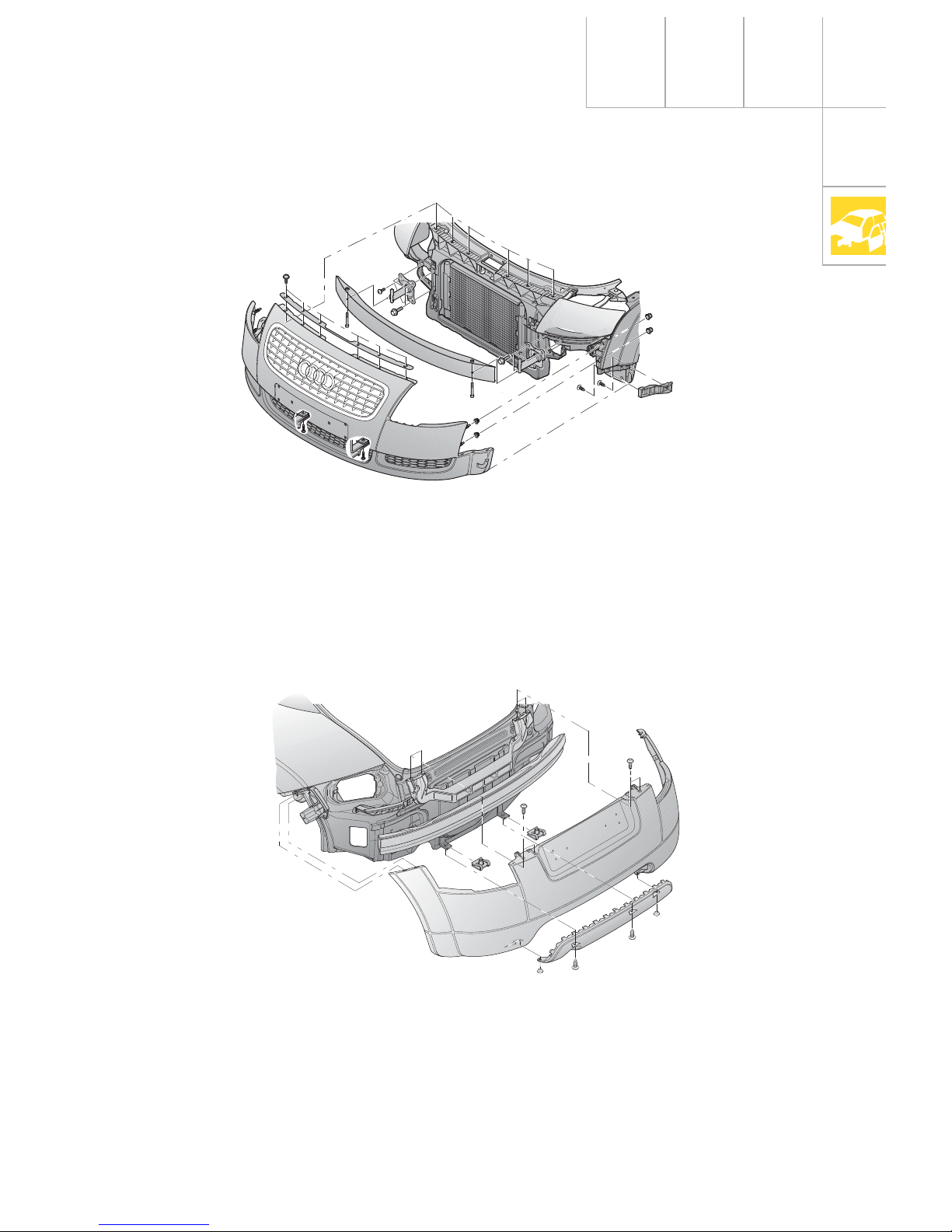
The rear bumper comprises a total of 4 parts:
the bumper panel, the rear cover, the aluminium cross-member and the central locating
element.
The guide profiles attached to the left and
right wings ensure an even gap all round.
A zero joint is created by attaching the bumper to the wing by means of threaded bolts as
well as nut and washer combinations.
The rear cover is available in two versions
depending on engine variant (TT has one
tailpipe, the TTS two). A seamless transition to
the body side section (zero joint) is produced
by means of 2 bolts on each body side section.
Body
The front bumper comprises two parts: the
cover panel and a decorative grille. The bumper carrier is made of aluminium and bolted to
the side members by impact absorbing elements.
SSP207/74
SSP207/75
Special features
Front bumper
Rear bumper
10
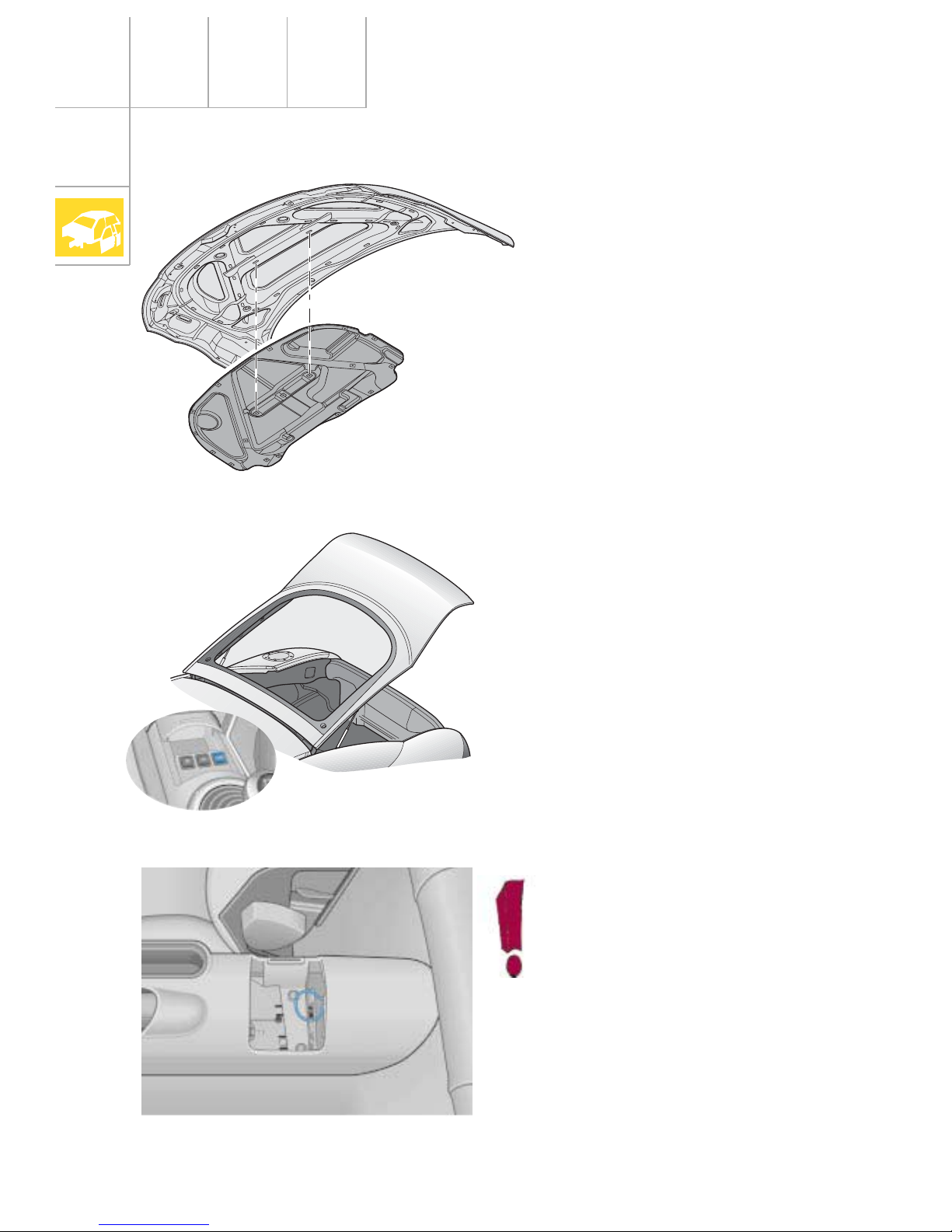
Bonnet
Tailgate
The bonnet is made of aluminium to save
weight.
The tailgate can only be opened from the
interior by means of the switch in the central
console or by radio-wave remote control. The
tailgate does not have a lock cylinder or a
handle.
The tailgate has a single-joint hinge.
Body
SSP207/78
SSP207/76
If the electrical system fails, the tailgate can be released in an emergency
by means of the cable pull located
below the rear central console cover.
SSP207/77
11
Taillights
To replace the filament lamps, the complete
taillight unit is removed without needing any
tools. Flaps are attached to the luggage compartment linings on the left and right. The
light cluster is secured on the inside by means
of 2 captive knurled bolts. On the outside, the
taillight is engaged in a ball head.
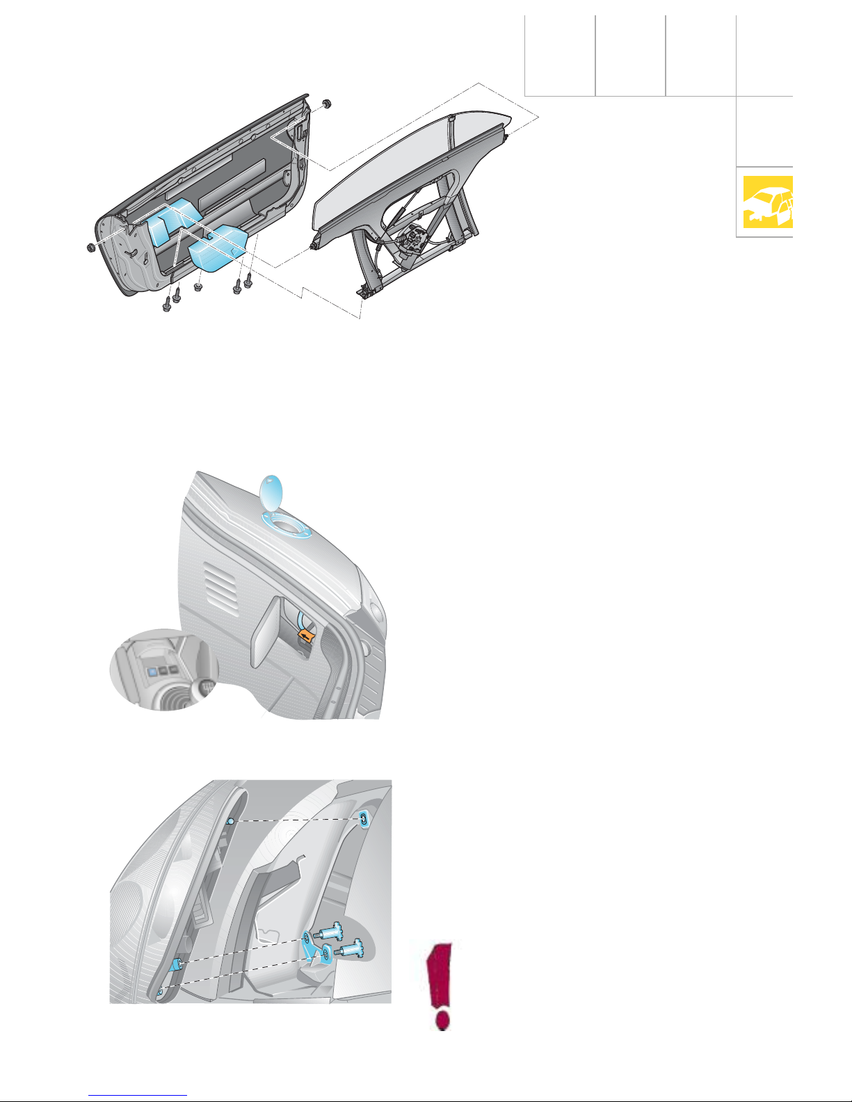
Doors
Fuel filler flap
The door component carrier is made of aluminium and can be adjusted for length, height
and inclination.
Additional side protection pads protect the
pelvis area.
The fuel filler flap is made of aluminium. It can
only be opened electrically via a switch in the
central console.
The fuel filler flap is attached from the exterior
with three anti-theft-protected bolts plus four
decorative bolts.
If the electrical system fails, the fuel filler flap
can be opened via an emergency release
mechanism in the luggage compartment. For
this purpose, it is necessary to open the flap in
the side trim panel on the right-hand side of
the luggage compartment and pull the cable
in the direction indicated on sticker.
SSP207/56
The light cluster can be adjusted along
the vehicle’s longitudinal axis by
means of the threaded sleeves.
SSP207/47
The doors of the Audi TT Coupé are frameless
and of two-piece construction.
The door panel is made of steel with a bolted
high-strength side reinforcement integrated in
the door.
SSP207/72
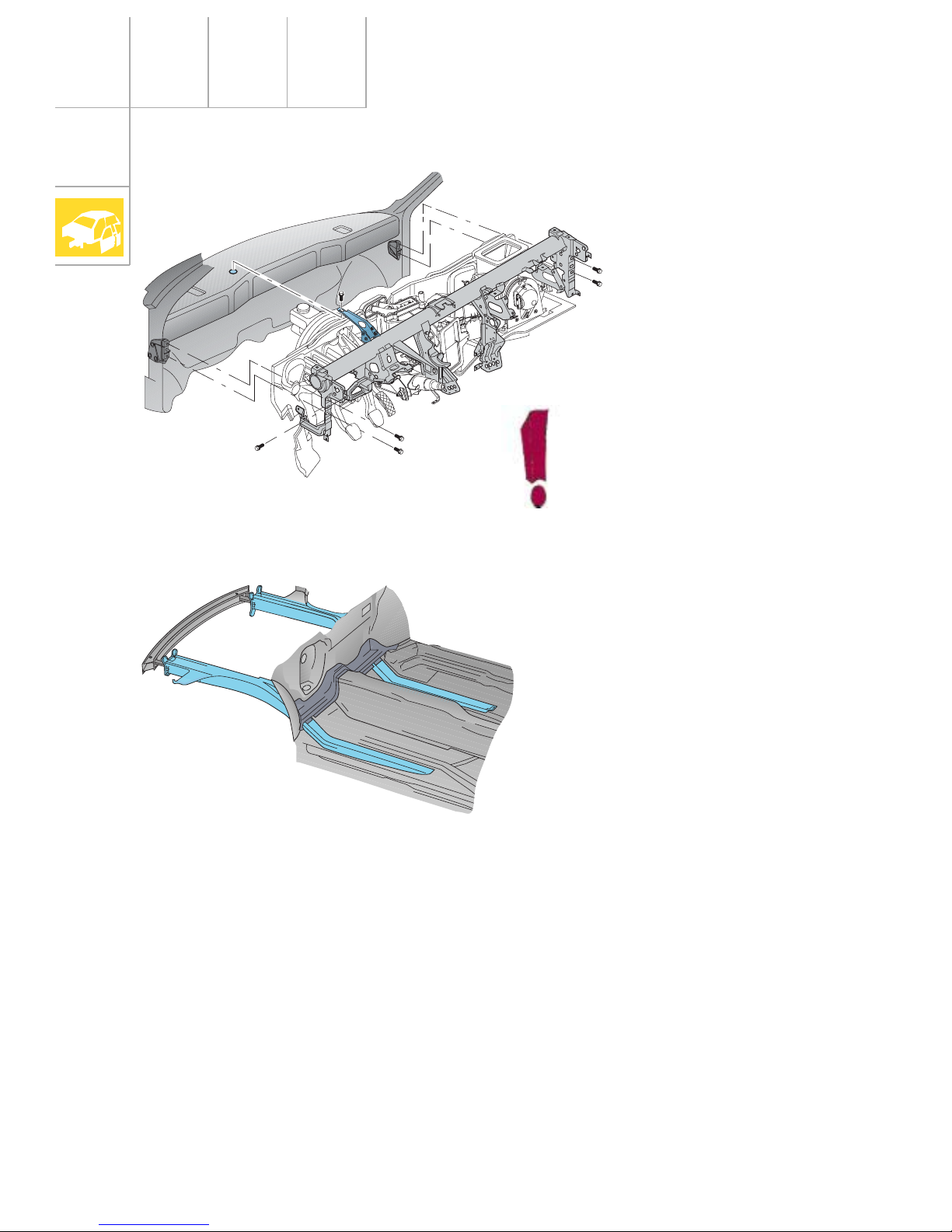
12
Dash panel
When removing the cross-tube,
please note that one of the fastening bolts is located on the outside
in the plenum chamber. To remove
this bolt, it is necessary to remove
the wiper linkage.
The vehicle front-end area deforms in a predefined manner, absorbing the impact energy
without impairing the stability of the occupant
cell. The side members are manufactured
from 2-, 3- and 1.5-mm-thick mash-welded
metal plates. In the case of a side impact, the
strong cross members will also deform on the
side of the body facing away from the impact
to absorb some of the impact energy.
The body structure of the vehicle rear-end
area is designed in such a way that, firstly, the
integrity of the fuel system remains largely
intact and, secondly, the load on the
occupants is kept to a minimum even in
serious accidents.
The Audi TT Coupé therefore complies with
the statutory crash requirements as well as
the laws relating to frontal and side impacts
due to enter into effect in the EU and USA.
Structure
SSP207/15
Body
SSP207/79
13
To absorb the load resulting from a side
impact, the body structure is extremely rigid
even though the B-pillar is not continuous. An
additional transverse support extending from
base of the B-pillar to the rear seat crossmember minimises cell deformation and the
rate of intrusion into the side structure. This
leads to low occupant loads.
Since the deformation path for energy absorption is very limited during a side impact,
various design measures are necessary to perform this task effectively.
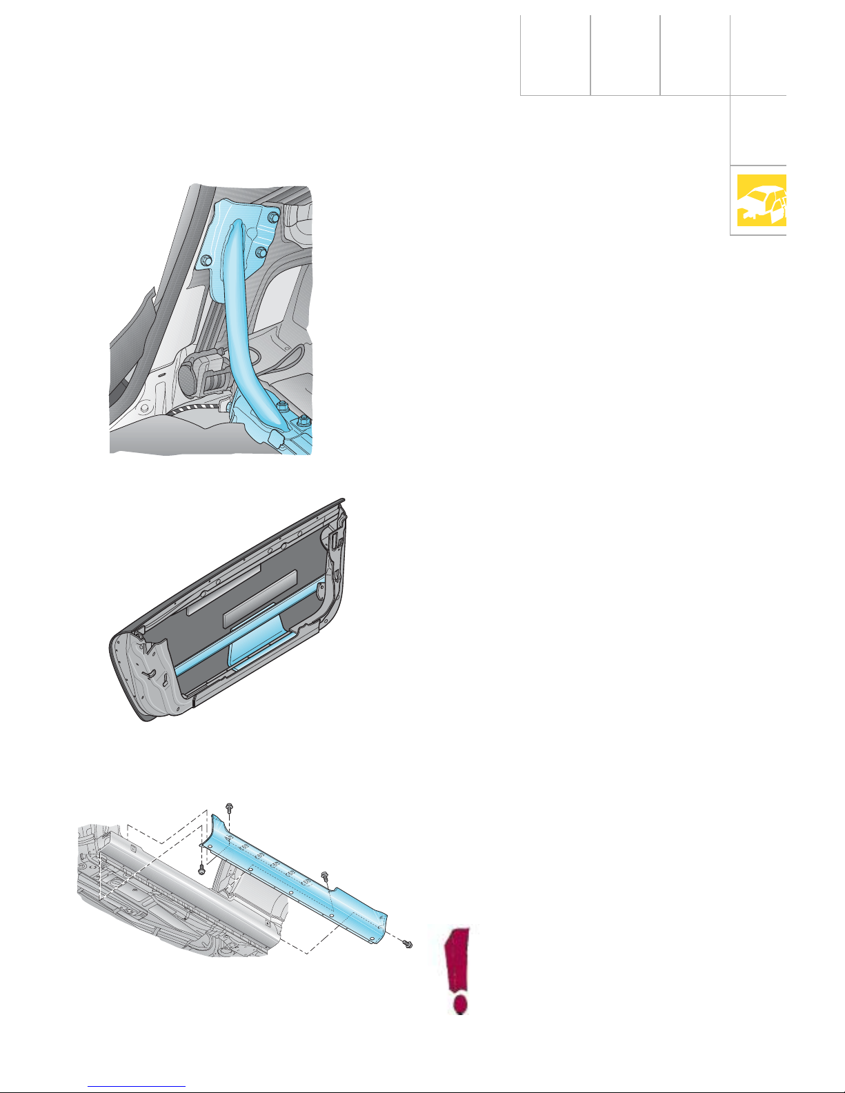
These include the side reinforcements made
of high-strength extruded aluminium sections
in the doors. The double-rectangular section
can absorb large mounts of energy .
During a side impact, the forces acting on the
vehicle are distributed via the side reinforcements in the doors to the sill and the A- and Bpillars.
The strong sill also absorbs energy and simultaneously transmits this energy to the stable
floorpan assembly.
The sill trim is made of steel and is secured to
the sill with 17 bolt + washer combinations.
Be careful when placing the car on
a lift support, otherwise the door
sill may become dented.
SSP207/5
SSP207/9
SSP207/45
B-pillar
Side reinforcements in the doors
Door sill
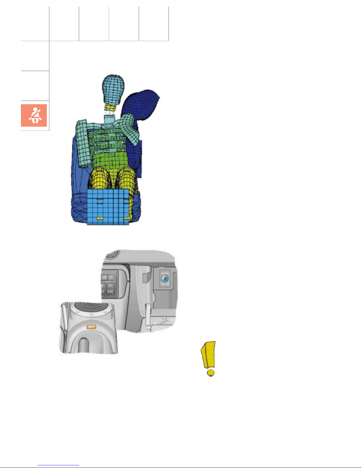
14
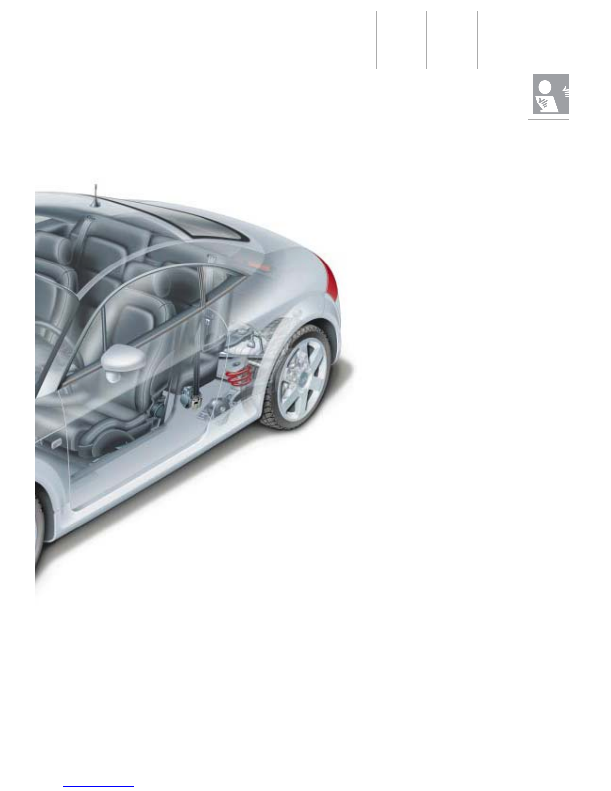
Vehicle safety
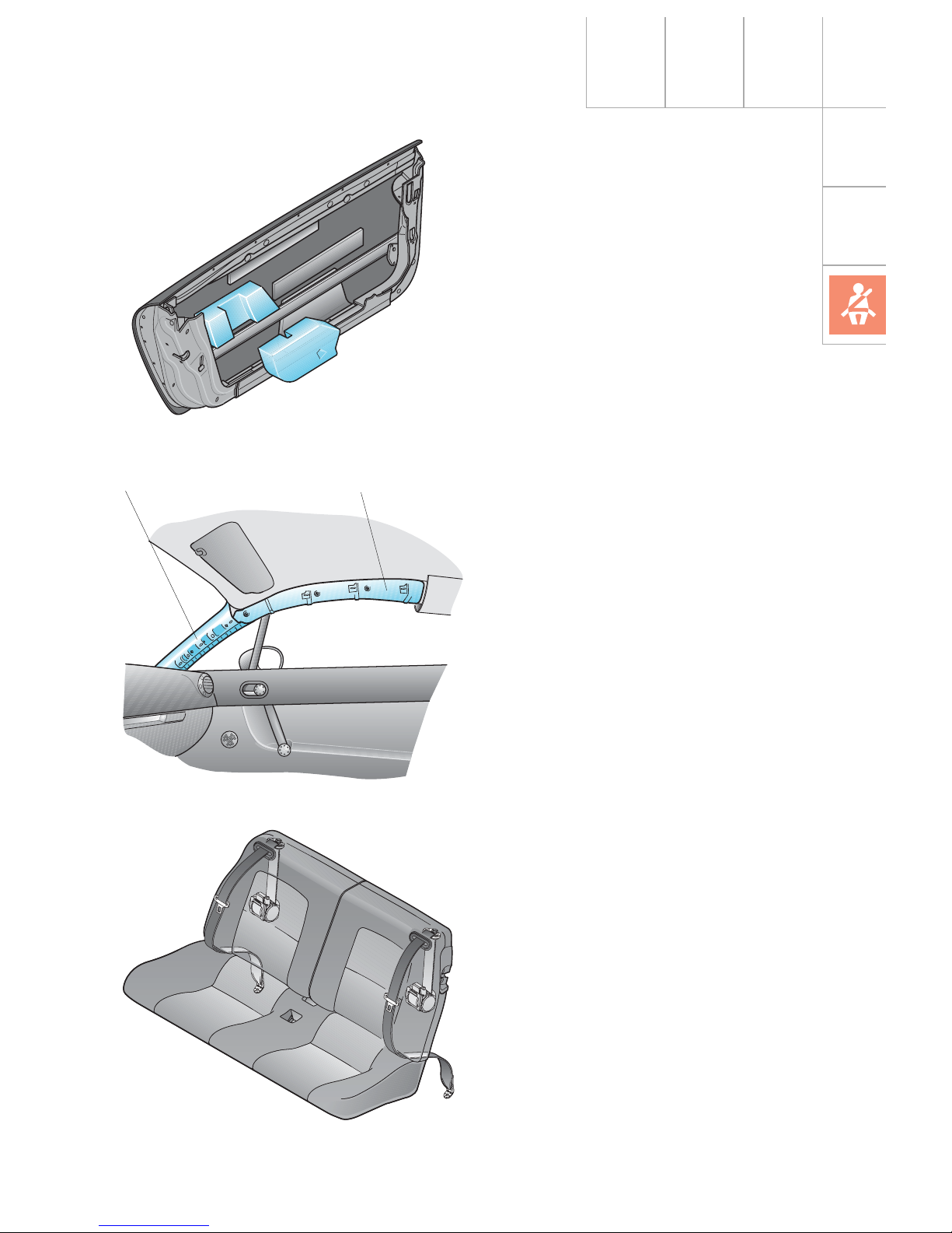
The Audi TT Coupé has head-thorax side airbags for the driver and front passenger.
These side airbags are integrated in the seat
backrests and extend from the rib cage area
up to the head when inflated.
When the side airbag is tripped, the head and
neck areas are thus provided with better protection.
In the Audi TT Coupé, the belt tensioners can
be fired independently of the airbags depending on how the trigger criteria are defined.
The Audi TT Coupé has a disable function for
deactivating the front passenger airbag.
When using Reboard child seats on the front
passenger seat, the driver must disable the
front passenger airbag with the vehicle key via
the key switch located inside the glove box
(see Operating Manual Audi TT Coupé).
A yellow indicator light in the
central console indicates when
the airbag is deactivated.
SSP207/80
SSP207/81
Occupant protection
15
During a side impact, the vehicle occupant is
inevitably subjected to a relative movement
towards the force application point and away
from the deformation path.
Therefore, it is very important to ensure that
the contact surface between the occupant and
the vehicle is large and energy-absorbing.
The side protection paddings made of plastic
foam protect the vehicle occupants in the pelvis and rib cage areas.
For protection of the head, a padding is also
integrated in the roof area.
An additional deformation element has been
welded onto the A-pillar.
These measures have enabled Audi to comply
with the new US head impact laws for the first
time.
SSP207/6
SSP207/7
Deformation element Roof padding
The rear seat has been approved as a Group 3
child seat (approx. 6 - 12 years) and is compliant with ECE-R44. Children of heights ranging
from 1.30 m to 1.50 m without raised seat
swab.
SSP207/73
16
Vehicle safety
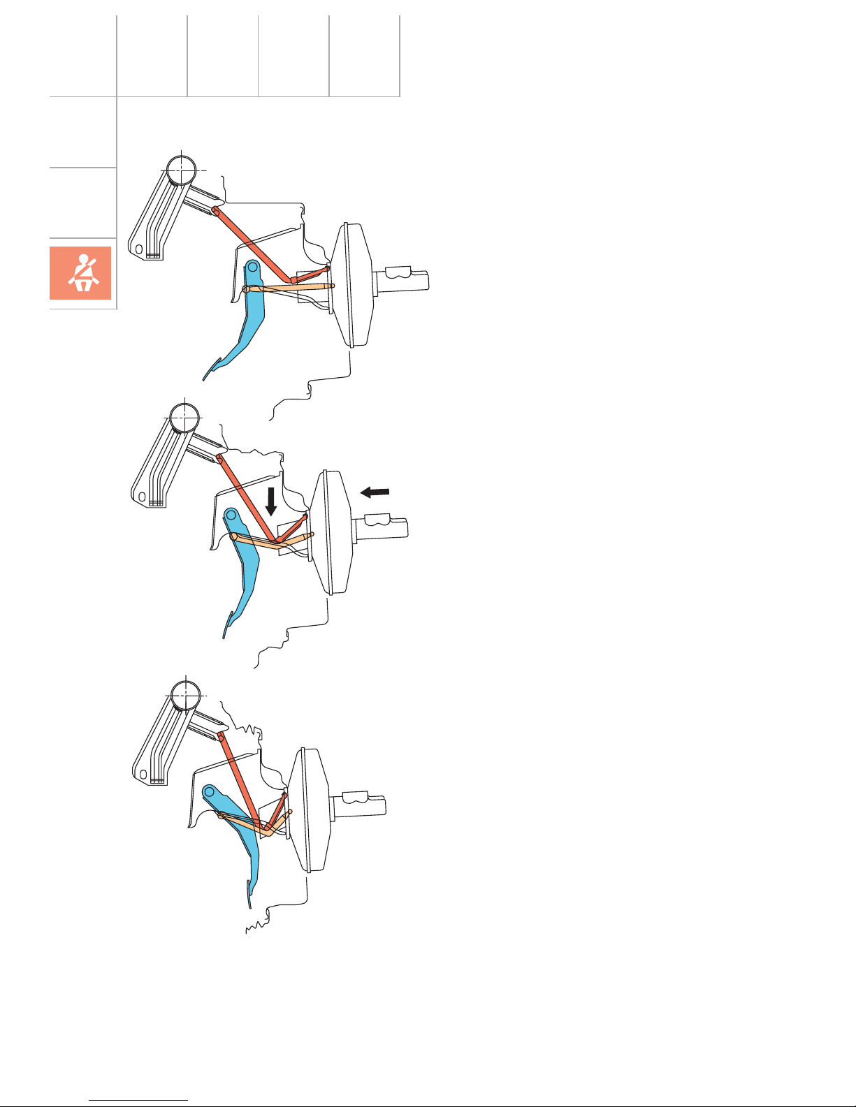
To minimise the risk of foot injuries in serious
head-on collisions, the brake pedal is swung
away from the foot area by means of a collapsing support if severe deformation of the
vehicle occurs.
This function is determined by deformation of
the engine bulkhead and is not dependent on
operation of the brake pedal.
In the event of a frontal crash, the foot controls are displaced towards the central tube.
This causes the collapsing support to deflect
and the piston rod to buckle.
The pedal footplate is swung up to 170 mm
away from the foot area.
The buckling of the piston rod and the deformation work resulting from this dampens the
angular movement of the braking foot. This
reduces the acceleration forces (braking foot)
which normally arise considerably.
SSP207/126
17
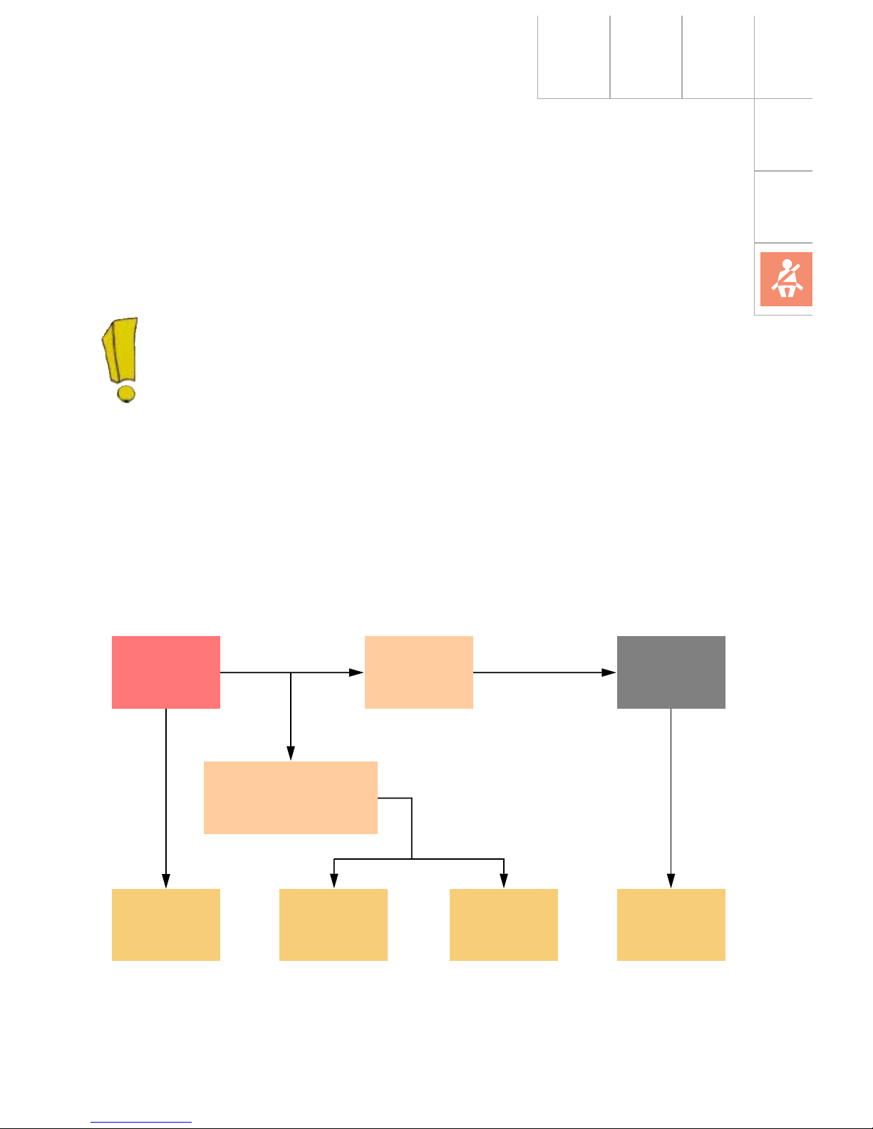
The central locking control unit receives this
signal simultaneously and unlocks the vehicle
doors. The hazard warning lights are activated
automatically and the interior lighting is switched on.
A restart function enables the engine to be
restarted after an accident and it can be
moved from the danger zone under its own
power.
The fuel tank is made of plastic and is housed
in a protected position in front of the rear axle.
Airbag
control unit
Motronic
control unit
Fuel relay
Door locking
unit
Hazard
warning
switch
Interior
lighting
Central locking control
unit and anti-theft
warning system
Fuel pump
Fuel cut-off
J234 J220 J17
J379
F220...223E3 G6
The Audi TT Coupé is the first Audi to
be equipped with a fuel cut-off.
In connection with an airbag trigger
mechanism (crash signal output), the
Motronic control unit switches the fuel
pump off.
18
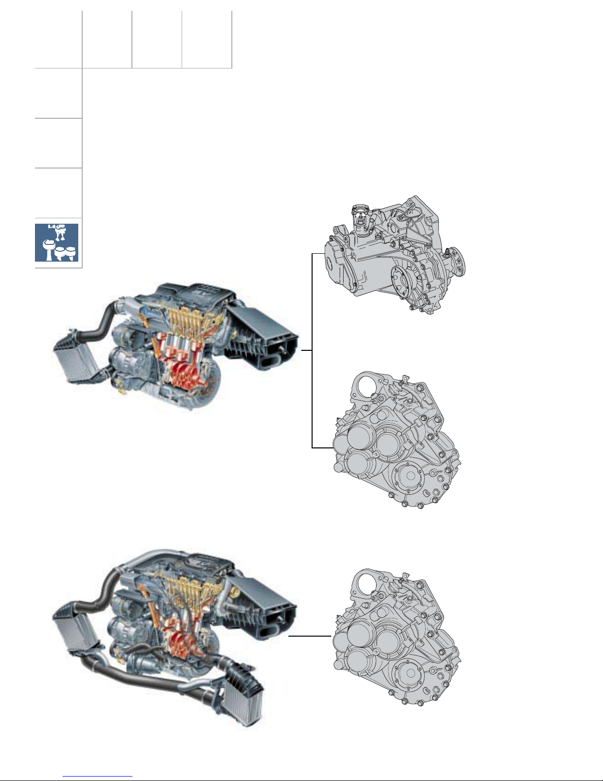
Engine and gearbox combinations
MQ 350 5-speed quattro 02M.3
Gearbox Code
MQ 250 5-speed front 02J.N
MQ 350 6-speed quattro 02M.1
1.8-ltr. 5V turbocharged
AJQ
132 kW/180 bhp
1.8-ltr. 5V turbocharged
APX
165 kW/225 bhp
SSP207/33
SSP207/53
SSP207/14
SSP207/33
Drive units
SSP207/13
Engine
DZF
DXW
DQB
19
200
180
160
140
120
100
80
60
40
20
0
1000
400
360
320
280
240
200
160
120
80
40
0
2000 3000 4000 5000 6000 7000
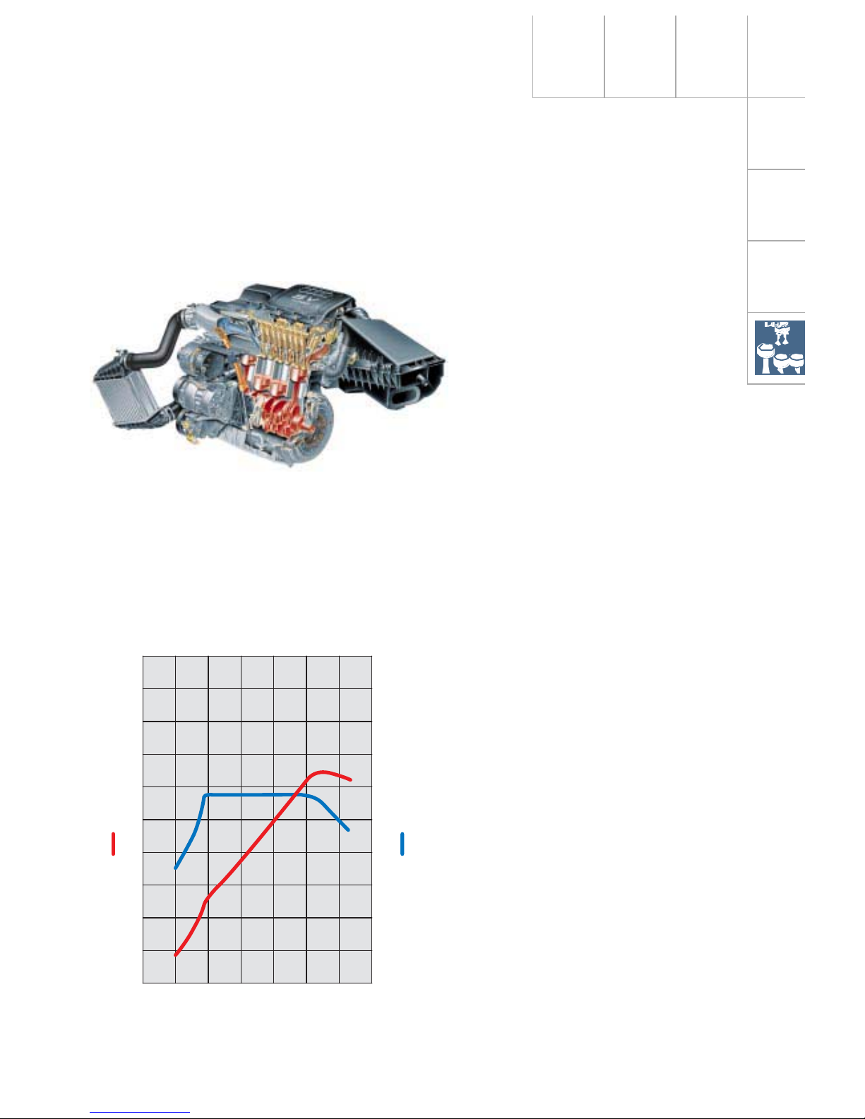
Specifications
Engine code: AJQ
Type: 4-cylinder 5-valve
four-stroke petrol engine
with exhaust gas
turbocharger
Valve timing: Double overhead
camshaft (DOHC)
Displacement: 1781 cm
3
Bore: 81 mm
Stroke: 86.4 mm
Compression
ratio: 9.5 : 1
Torque: 235 Nm
at 1950 - 4700 rpm
Rated output: 132 kW/180 bhp
at 5500 rpm
Engine management: ME 7.5
Fuel: Premium unleaded 98 RON
(RON 95 can be used, but
reduces power output)
1.8-ltr. 5V turbocharged engine
132 kW AJQ
Technical modifications:
Basic 110 kW (150 bhp)
– EU II + D3
– electronic throttle control
– “Tumble“ duct
(For details of the tumble duct in the intake
system, refer to SSP 198)
– Engine control unit (characteristic curves
adapted)
– CAN-BUS with TCS/EDL/ESP
– electr. activated air divert control valve
SSP207/13
SSP207/62
Engine speed [rpm]
Torque [Nm]
Output [kW]
20
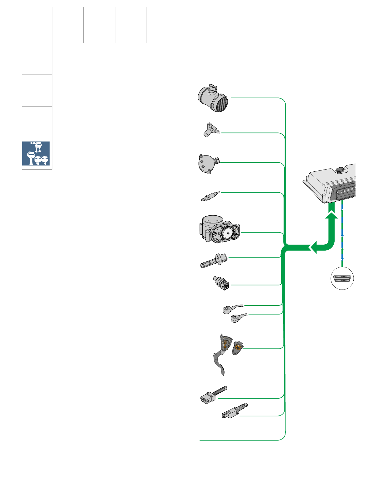
System overview – 1.8-ltr. 132 kW 5V turbocharged
Drive units
Hot-film air mass meter G70
Sensors
Auxiliary signals:
Pressure switch for power steering F88
Cruise control
Intake manifold pressure sender G71
Engine speed sender G28
Hall sender G40
Lambda probe G39
Throttle valve control unit J338
with angle sender G187 for
throttle valve gear G186
Intake air temperature sender G42
Coolant temperature sender
G2 and G62
Knock sensor 1 (cyl. 1 - 2) G61
Knock sensor 2 (cyl. 3 - 4) G66
Accelerator pedal module with accelerator position sender G79 and G185
Brake light switch F and brake
pedal switch F47
Clutch pedal switch F36
21
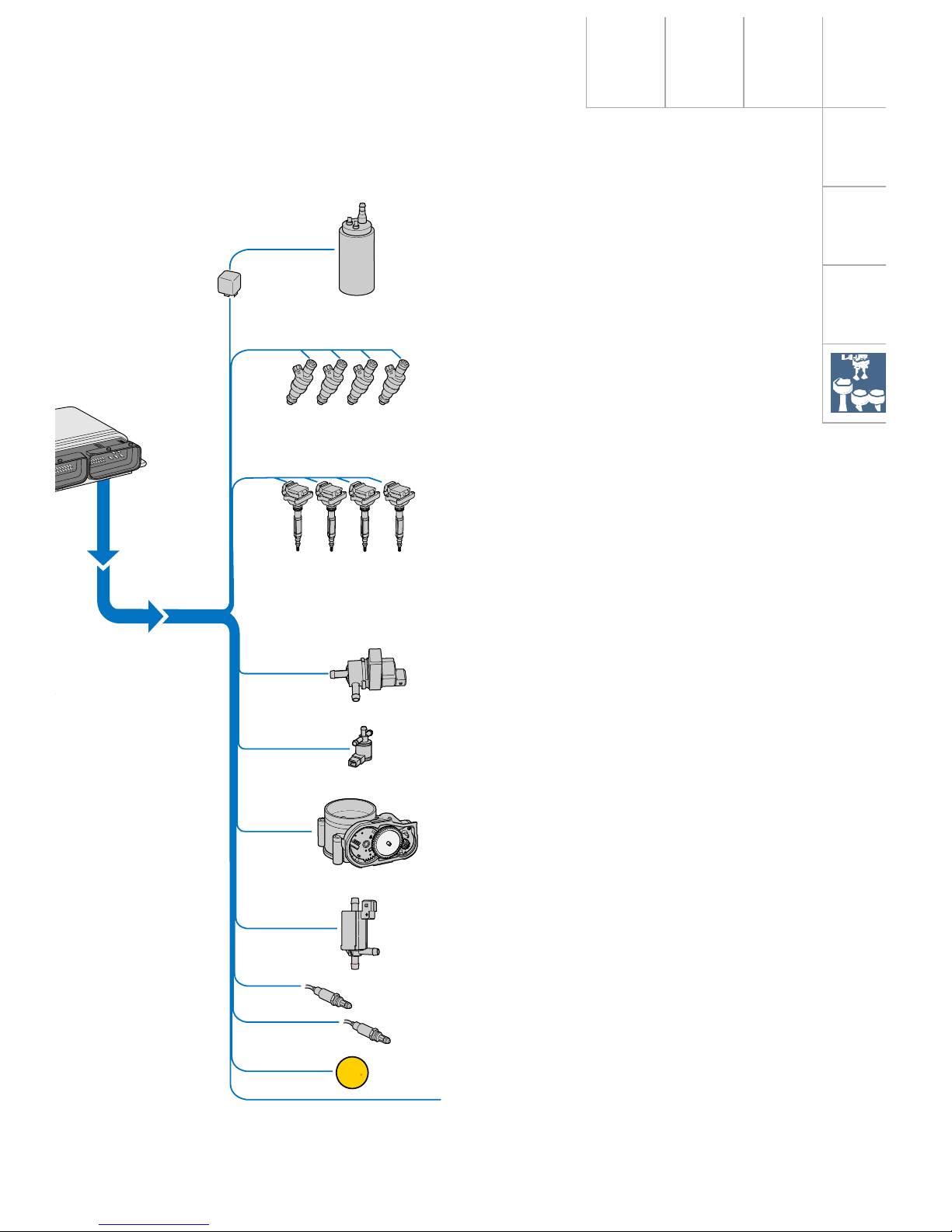
EPC
SSP207/46
Fuel pump relay J17 and
fuel pump G6
Actuators
Injection valves N30, N31, N32,
N33
Power output stage N122 and
ignition coils N (1st cyl.),
N128 (2nd cyl.),
N158 (3rd cyl.)
and N163 (4th cyl.)
with integrated power output
stage
Solenoid valve for activated
charcoal canister N80
Solenoid valve for charge pressure limitation N75
Throttle valve control unit J338
with throttle valve gear G186
Air recirculation valve for turbocharger N249
Heater for lambda probe Z19
Auxiliary signals
Fault lamp for electronic throttle
control K132

22
Turbocharged 1.8-ltr. 132 kW 5V engine
Motronic ME 7.5
Components
A Battery
E45 Switch for cruise control system
E227 Button for cruise control system
F Brake light switch
F36 Clutch pedal switch
F88 Power steering (pressure switch)
G6 Fuel pump
G28 Engine speed sender
G39 Lambda probe
G40 Hall sender with quick-start sender
wheel
G42 Intake air temperature sender
G61 Knock sensor 1
G62 Coolant temperature sender
G66 Knock sensor 2
G70 Air mass meter
G71 Intake manifold pressure sender
G79 Accelerator position sender
G186 Throttle valve gear
(electronic throttle control)
G187 Throttle valve drive angle sender 1
G888 Throttle valve drive angle sender 1
J17 Fuel pump relay
J220 Motronic control unit
K132 Fault lamp for electronic throttle
control
M9/10 Stop lights
N Ignition coil
N30...33 Injection valves
N75 Solenoid valve for charge pressure
limitation
N80 Solenoid valve for activated charcoal
canister
N128 Ignition coil 2
N158 Ignition coil 3
N163 Ignition coil 4
N249 Air recirculation valve for
turbocharger
P Spark plug socket
S Fuse
Q Spark plugs
Z19 Heater for lambda probe
Auxiliary signals
CAN-BUS H =
CAN-BUS L =
A Engine speed signal (out)
B Fuel consumption signal (out)
C Road speed signal (in)
D Air-conditioner compressor signal (in-out)
E Air conditioning ready (in)
F Crash signal (in) from airbag control
unit
G Alternator terminal DF/DFM (in)
W- line (in-out)
}
Databus drive
Input signal
Output signal
Positive
Earth
Bidirectional
For the applicable Fuse No. and
amperage, please refer to the current
flow diagram.
Function chart
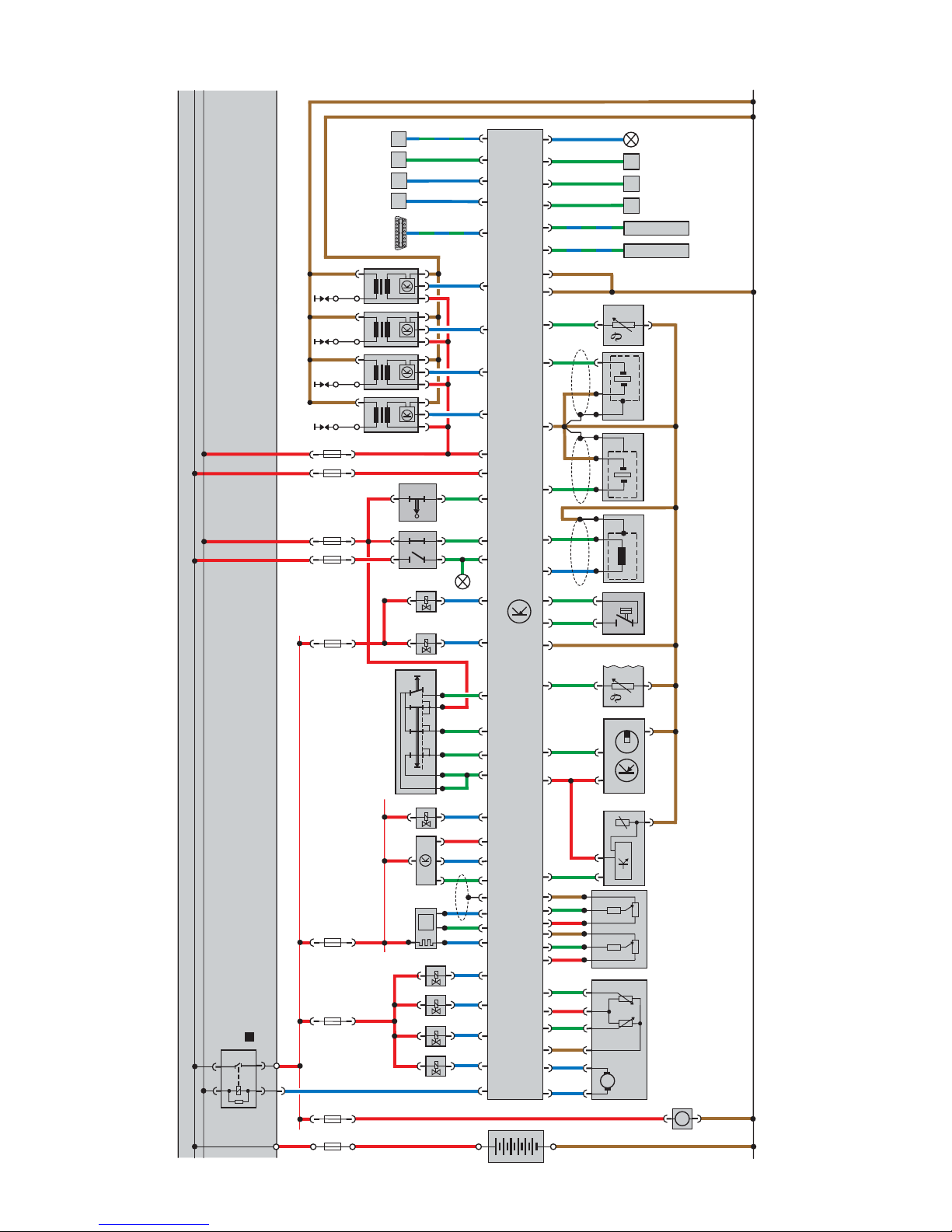
30
15
15 55 49 14 9
31
N33
F
S
+
-
A
J220
G79
N249
CAN - BUS H
30
15
B
J17
M
λ
3086
8785
DA
4
E F
N158 N163
CAN - BUS L
M
Q
P
Q
P
Q
P
Q
P
+
-
G
C
SSSS
G188G187G186
G6
G71
+
-
N75
F36
E227E45
N80
G70G39
Z19
G40 G62 F88 G28 G61 G66 G42
K132
M9/10
+
--
++
SS SS
N128N
N32N31N30
A
31
J220
P
23
SSP207/25
Dieses Dokument wurde erstellt mit FrameMaker 4.0.4.
24
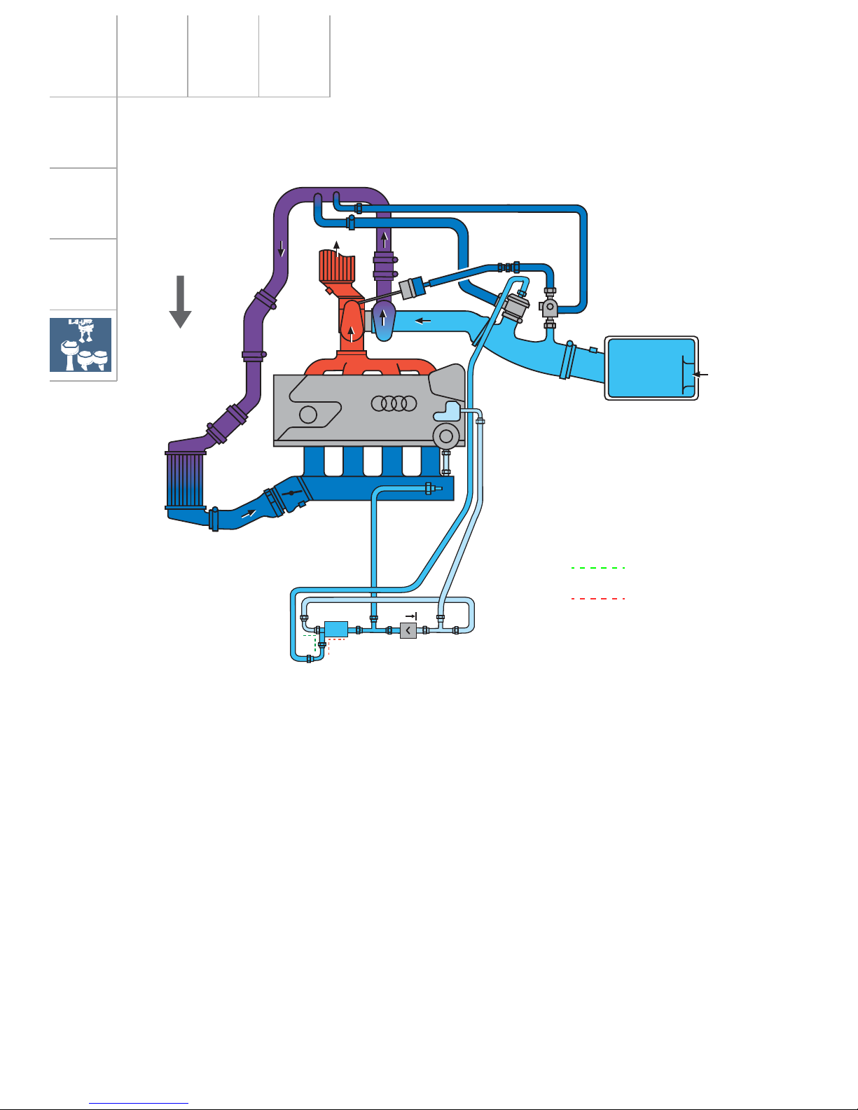
5V Turbo
N249
The turbocharging system comprises the following components:
– Exhaust emission turbocharger
– Charge air cooler
– Charge pressure control
– Air divert control in overrun
The flow energy of the exhaust emissions is
transferred to the fresh air entering the exhaust
gas turbocharger. In the process, the air required
for combustion is compressed and the volume
of air entering the cylinders per working cycle is
thus increased.
The air temperature, increased by compression,
is again reduced in the charge air cooler. Since
the density of the cooled air is higher, the
amount of fuel-air mixture entering the engine is
greater, too.
The result is an increase in power output for the
same displacement and engine speed.
In the case of the 1.8-ltr. 5V turbocharged
engine, turbocharging is also used to provide
high torque from the bottom end to the top end
of the rev band.
Charge pressure increases in proportion to the
turbocharger speed. The charge pressure is
limited to prolong the life of the engine. The
charge pressure control performs this task.
The air divert control prevents the turbocharger
slowing down unnecessarily if the throttle valve
closes suddenly.
Charging
SSP207/20
Drive units
energised
de-energised
Direction of travel

25
5V Turbo
N249
J220
N75
G70 G28 G69
Charge pressure control
If the control fails, the maximum charge pressure is limited to a basic charge pressure
(mechanical charge pressure).
If the bypass is closed, the charge pressure rises.
In the lower engine speed range, the turbocharger supplies the charge pressure required to
develop high torque or the required volume of
air.
As soon as the charge pressure has reached the
calculated charge pressure, the bypass opens
and a certain quantity of exhaust gas is ducted
past the turbine. The turbocharger motor speed
decreases, and so too does the charge pressure.
For more detailed information regarding charge
pressure control, please refer to SSP 198.
The engine control unit calculates the charge
pressure setpoint from the engine torque
request.
The engine control unit regulates the charge
pressure as a function of the opening time of the
solenoid valves for charge pressure limitation
N75. For this purpose, a control pressure is
generated from the charge pressure in the compressor housing and the atmospheric pressure.
This control pressure counteracts the spring
pressure in the charge pressure control valve
(vacuum box) and opens or closes the waste
gate valve in the turbocharger.
In the de-energised state, the solenoid valve N75
is closed and the charge pressure acts directly
on the vacuum box. The charge pressure control
valve opens at low charge pressure.
SSP207/22
energised
de-energised
Waste gate valve
26
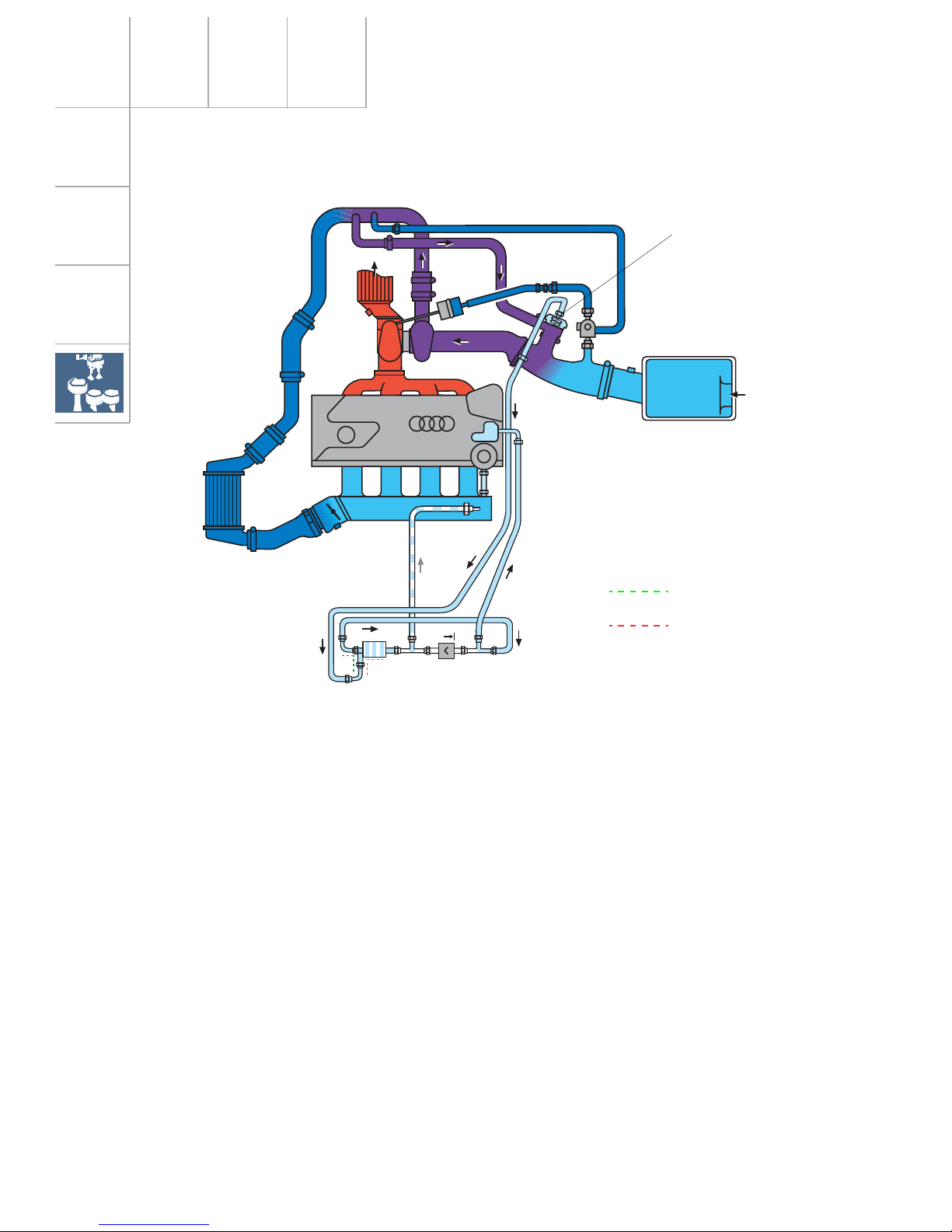
5V Turbo
N249
When the throttle valve is closed, it produces
a backpressure in the compressor circuit due
to the charge pressure still present. This causes the compressor wheel to decelerate
rapidly. When the throttle valve is opened, the
speed of the turbocharger must again be
increased. The air divert control in overrun
prevents turbo lag, which would otherwise
occur.
The air recirculation valve is a mechanically
activated and pneumatically controlled spring
diaphragm valve. It is also activated via an
electrically activated air recirculation valve for
turbocharger N249. This, in connection with
the vacuum reservoir, enables the air recirculation valve N249 to operate independently of
the intake manifold pressure. If the air recirculation valve fails, control takes place as a
result of the engine vacuum downstream of
the throttle valve.
As soon as the throttle valve is closed, the air
recirculation valve briefly closes the compressor circuit.
The vacuum counteracts the spring in the
valve. The valve opens, and the compressor
and intake sides of the compressor circuit
close for a short period of time. There is no
deceleration of the compressor wheel.
When the throttle valve re-opens, the intake
manifold vacuum drops. The air recirculation
valve is closed by the spring force. The compressor circuit no longer closes briefly. Full
charger speed is available immediately.
For more detailed information regarding the
air divert control in overrun, please refer to
SSP 198.
Air divert control in overrun
SSP207/23
Drive units
energised
de-energised
Air recirculation valve
(pneumatic)
27
200
180
160
140
120
100
80
60
40
20
0
1000
400
360
320
280
240
200
160
120
80
40
0
2000 3000 4000 5000 6000 7000
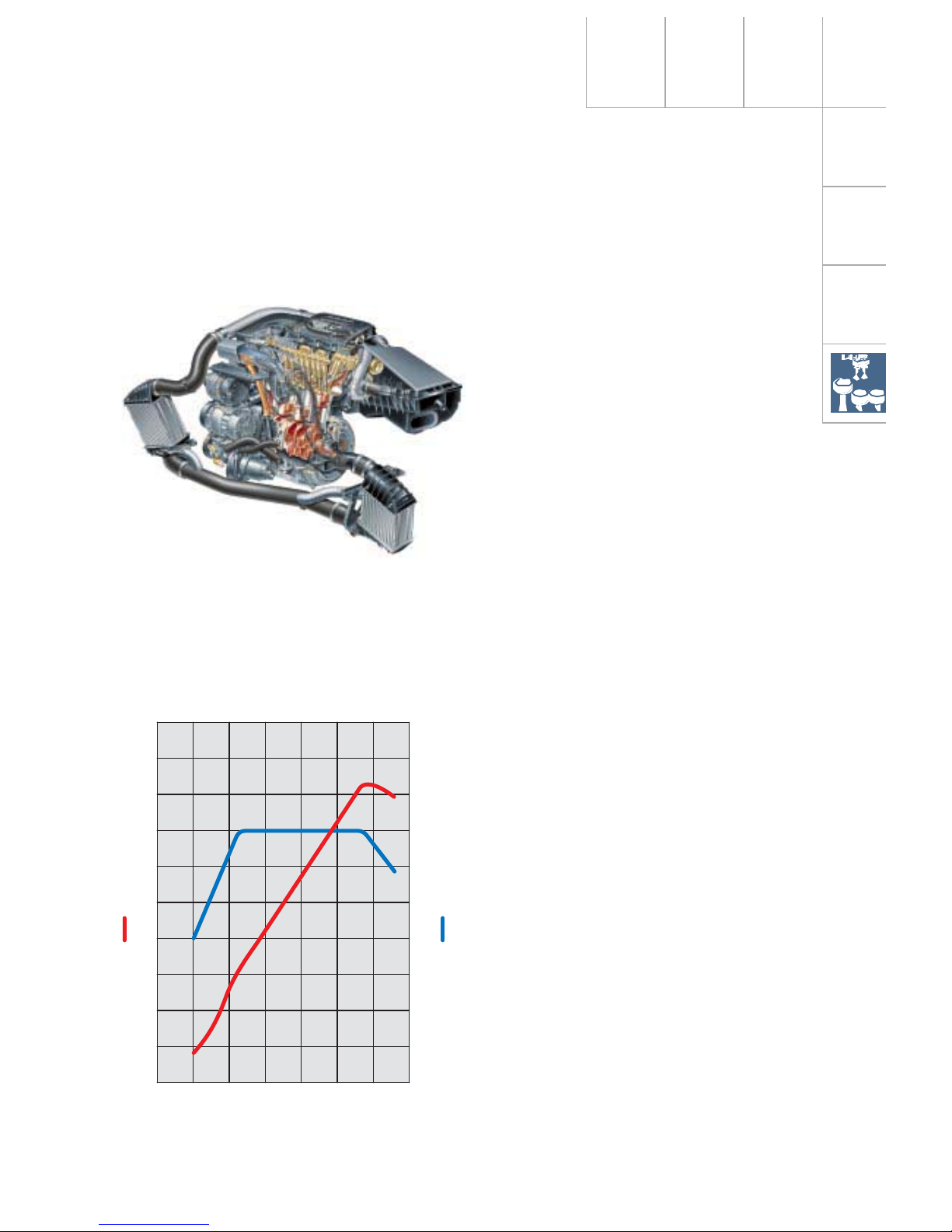
Technical modifications:
Basic 132 kW (180 bhp)
– Cooling water afterrun pump (approx. 10 min)
– Secondary air system
– Piston (modified), thus changing the
compression ratio to 9.0 : 1 from 9.5 : 1
– Manifold (new exhaust and flange)
– When EU III takes effect, there will be a 2nd
lambda probe downstream of catalytic
converter for catalyst monitoring
– 2 in-line charge air coolers
– Injection valves (higher flow)
– Quick-start sender wheel
– Piston cooling by oil injectors
(volumetric flow adaptation)
– Hot-film air mass meter with reverse flow
detector HFM5 integrated in the intake air
filter upper section
– Single-flow throttle valve unit integrated in
the electronic throttle control positioner
1.8-ltr. 5V 165 kW APX
turbocharged engine
SSP207/14
SSP207/63
Specifications
Engine code: APX
Type: 4-cylinder 5-valve
four-stroke-petrol engine
with exhaust gas
turbocharger
Valve timing: Double overhead
camshaft (DOHC)
Displacement: 1781 cm
3
Bore: 81 mm
Stroke: 86.4 mm
Compression ratio: 9 : 1
Rated output: 165 kW at 5900 rpm
max. torque: 280 Nm at 2200 to
5500 rpm
Engine management: ME 7.5
Fuel: Premium unleaded 98 RON
Exhaust gas
treatment: Twin-flow catalytic
converter, one heated
lambda probe upstream
and downstream of the
catalytic converter
Engine speed [rpm]
Torque [Nm]
Output [kW]
28
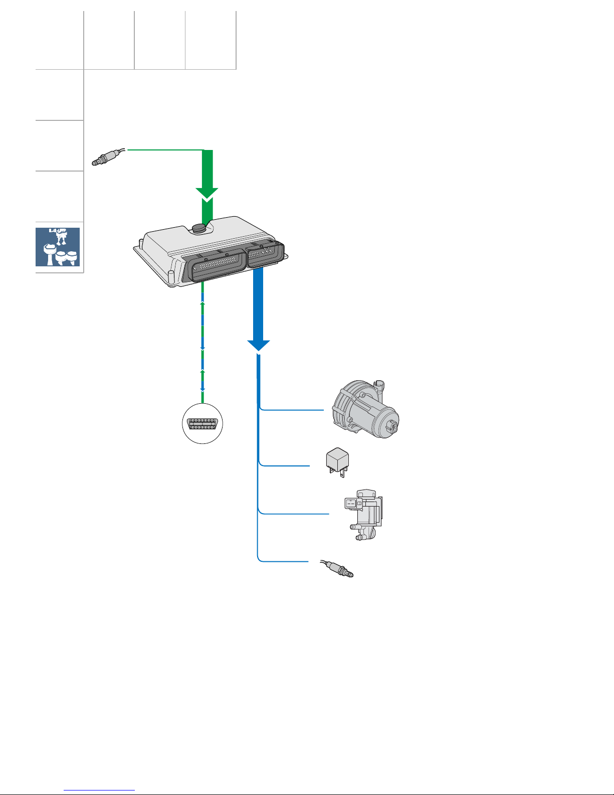
Extended system overview - 1.8-ltr. 165 kW 5V engine
Drive units
The secondary air system in the 1.8-ltr. 5V
engine developing 165 kW ensures that the
exhaust emissions comply with the EU III+D3
standard.
A probe will be installed downstream of the
catalytic converter to meet the requirements
stipulated in EU III.
SSP207/103
Lambda probe downstream of catalytic converter G130 when EU III
takes effect
Motronic control unit J220
Secondary air pump motor V101
Secondary air pump relay J299
Secondary air injection valve N112
Heater for lambda probe
down-stream of catalytic
converter Z29
when EU III takes effect
 Loading...