

Page 1
Protected by copyright. Copying for private or commercial purposes, in part or in whole, is not
permitted unless authorised by AUDI AG. AUDI AG does not guarantee or accept any liability
with respect to the correctness of information in this document. Copyright by AUDI AG.
Service
Workshop Manual
Audi TT 1999 ➤
Running gear, self-diagnosis
Edition 07.2004
Service Department. Technical Information
Page 2

Protected by copyright. Copying for private or commercial purposes, in part or in whole, is not
permitted unless authorised by AUDI AG. AUDI AG does not guarantee or accept any liability
with respect to the correctness of information in this document. Copyright by AUDI AG.
Service
List of Workshop Manual Repair GroupsList of Workshop Manual
Repair GroupsList of Workshop Manual Repair Groups
Re pa ir G ro up
01 - Self-diagnosis, electrical checks
Technical information should always be available to the foremen and mechanics, because their
careful and constant adherence to the instructions is essential to ensure vehicle road-worthiness and
safety. In addition, the normal basic safety precautions for working on motor vehicles must, as a
matter of course, be observed.
All rights reserved.
No reproduction without prior agreement from publisher.
Copyright © 2010 Audi AG, Ingolstadt A0057006120
Page 3

Protected by copyright. Copying for private or commercial purposes, in part or in whole, is not
permitted unless authorised by AUDI AG. AUDI AG does not guarantee or accept any liability
with respect to the correctness of information in this document. Copyright by AUDI AG.
Audi TT 1999 ➤
Running gear, self-diagnosis - Edition 07.2004
Contents
01 - Self-diagnosis, electrical checks . . . . . . . . . . . . . . . . . . . . . . . . . . . . . . . . . . . . . . 1
1 Self-diagnosis . . . . . . . . . . . . . . . . . . . . . . . . . . . . . . . . . . . . . . . . . . . . . . . . . . . . . . . . . . . . 1
1.1 Basic notes on self-diagnosis . . . . . . . . . . . . . . . . . . . . . . . . . . . . . . . . . . . . . . . . . . . . . . . . 1
1.2 Function of the individual systems . . . . . . . . . . . . . . . . . . . . . . . . . . . . . . . . . . . . . . . . . . . . 2
1.3 Safety precautions . . . . . . . . . . . . . . . . . . . . . . . . . . . . . . . . . . . . . . . . . . . . . . . . . . . . . . . . 4
1.4 Requirements for test . . . . . . . . . . . . . . . . . . . . . . . . . . . . . . . . . . . . . . . . . . . . . . . . . . . . . . 4
1.5 Fault finding procedure . . . . . . . . . . . . . . . . . . . . . . . . . . . . . . . . . . . . . . . . . . . . . . . . . . . . 5
1.6 Road test . . . . . . . . . . . . . . . . . . . . . . . . . . . . . . . . . . . . . . . . . . . . . . . . . . . . . . . . . . . . . . 6
1.7 Connecting vehicle diagnostic, testing and information system VAS 5051 A . . . . . . . . . . 7
2 CAN bus . . . . . . . . . . . . . . . . . . . . . . . . . . . . . . . . . . . . . . . . . . . . . . . . . . . . . . . . . . . . . . . . 9
2.1 Testing a “two-wire data bus system” . . . . . . . . . . . . . . . . . . . . . . . . . . . . . . . . . . . . . . . . 9
3 ABS/EDL and ABS/EDL/TCS, ITT Mark 20 without ESP . . . . . . . . . . . . . . . . . . . . . . . . . . 13
3.1 Electrical/electronic components and fitting locations . . . . . . . . . . . . . . . . . . . . . . . . . . . . 13
3.2 Faults displayed by warning lamps in instrument cluster . . . . . . . . . . . . . . . . . . . . . . . . . . 14
3.3 Performing self-diagnosis on the ABS/EDL and ABS/EDL/TCS, ITT Mark 20 without ESP
. . . . . . . . . . . . . . . . . . . . . . . . . . . . . . . . . . . . . . . . . . . . . . . . . . . . . . . . . . . . . . . . . . . . . . . . 17
3.4 Interrogating fault memory . . . . . . . . . . . . . . . . . . . . . . . . . . . . . . . . . . . . . . . . . . . . . . . . . . 17
3.5 Fault tables . . . . . . . . . . . . . . . . . . . . . . . . . . . . . . . . . . . . . . . . . . . . . . . . . . . . . . . . . . . . . . 18
3.6 Final control diagnosis . . . . . . . . . . . . . . . . . . . . . . . . . . . . . . . . . . . . . . . . . . . . . . . . . . . . 25
3.7 Basic setting . . . . . . . . . . . . . . . . . . . . . . . . . . . . . . . . . . . . . . . . . . . . . . . . . . . . . . . . . . . . 32
3.8 Erasing fault memory . . . . . . . . . . . . . . . . . . . . . . . . . . . . . . . . . . . . . . . . . . . . . . . . . . . . . . 38
3.9 End output . . . . . . . . . . . . . . . . . . . . . . . . . . . . . . . . . . . . . . . . . . . . . . . . . . . . . . . . . . . . . . 39
3.10 Renewing and coding control unit . . . . . . . . . . . . . . . . . . . . . . . . . . . . . . . . . . . . . . . . . . . . 39
3.11 Measured value block . . . . . . . . . . . . . . . . . . . . . . . . . . . . . . . . . . . . . . . . . . . . . . . . . . . . 42
3.12 Login procedure or coding II . . . . . . . . . . . . . . . . . . . . . . . . . . . . . . . . . . . . . . . . . . . . . . . . 46
3.13 Electrical check of ABS/EDL and ABS/EDL/TCS ITT Mark 20 without ESP . . . . . . . . . . . . 47
3.14 Connecting adapter V.A.G 1598/21 (test box) to ABS with EDL control unit J104 . . . . . . 48
3.15 Test table . . . . . . . . . . . . . . . . . . . . . . . . . . . . . . . . . . . . . . . . . . . . . . . . . . . . . . . . . . . . . . 50
4 ABS/EDL/TCS/ESP ITT Mark 20 . . . . . . . . . . . . . . . . . . . . . . . . . . . . . . . . . . . . . . . . . . . . 59
4.1 Retrofit installation of ESP . . . . . . . . . . . . . . . . . . . . . . . . . . . . . . . . . . . . . . . . . . . . . . . . . . 59
4.2 Electrical/electronic components and fitting locations . . . . . . . . . . . . . . . . . . . . . . . . . . . . 59
4.3 Faults displayed by warning lamps in instrument cluster . . . . . . . . . . . . . . . . . . . . . . . . . . 62
4.4 Performing self-diagnosis of ABS/EDL/TCS/ESP ITT Mark 20 system . . . . . . . . . . . . . . . . 65
4.5 Interrogating fault memory . . . . . . . . . . . . . . . . . . . . . . . . . . . . . . . . . . . . . . . . . . . . . . . . . . 65
4.6 Fault tables . . . . . . . . . . . . . . . . . . . . . . . . . . . . . . . . . . . . . . . . . . . . . . . . . . . . . . . . . . . . . . 66
4.7 Final control diagnosis . . . . . . . . . . . . . . . . . . . . . . . . . . . . . . . . . . . . . . . . . . . . . . . . . . . . 77
4.8 Basic setting . . . . . . . . . . . . . . . . . . . . . . . . . . . . . . . . . . . . . . . . . . . . . . . . . . . . . . . . . . . . 84
4.9 Performing zero compensation of steering angle sender G85 . . . . . . . . . . . . . . . . . . . . . . 99
4.10 Erasing fault memory . . . . . . . . . . . . . . . . . . . . . . . . . . . . . . . . . . . . . . . . . . . . . . . . . . . . . . 102
4.11 End output . . . . . . . . . . . . . . . . . . . . . . . . . . . . . . . . . . . . . . . . . . . . . . . . . . . . . . . . . . . . . . 103
4.12 Renewing and coding control unit . . . . . . . . . . . . . . . . . . . . . . . . . . . . . . . . . . . . . . . . . . . . 103
4.13 Measured value block . . . . . . . . . . . . . . . . . . . . . . . . . . . . . . . . . . . . . . . . . . . . . . . . . . . . 110
4.14 Login procedure or coding II . . . . . . . . . . . . . . . . . . . . . . . . . . . . . . . . . . . . . . . . . . . . . . . . 116
4.15 Electrical check of ABS/EDL/TCS/ESP ITT MARK 20 . . . . . . . . . . . . . . . . . . . . . . . . . . . . 118
4.16 Connecting test box V.A.G 1598 A with adapter cable (47-pin) V.A.G 1598/33 to ABS with
EDL control unit J104 . . . . . . . . . . . . . . . . . . . . . . . . . . . . . . . . . . . . . . . . . . . . . . . . . . . . 119
4.17 Test table . . . . . . . . . . . . . . . . . . . . . . . . . . . . . . . . . . . . . . . . . . . . . . . . . . . . . . . . . . . . . . 121
5 ABS/ESP, MK 60 Continental Teves Mark 60; Electronic Stabilisation Program, Continental
Teves Mark 60 . . . . . . . . . . . . . . . . . . . . . . . . . . . . . . . . . . . . . . . . . . . . . . . . . . . . . . . . . . 133
5.1 This self-diagnosis system is described exclusively in the “Guided fault finding” . . . . . . . . 133
Contents i
Page 4

Protected by copyright. Copying for private or commercial purposes, in part or in whole, is not
permitted unless authorised by AUDI AG. AUDI AG does not guarantee or accept any liability
with respect to the correctness of information in this document. Copyright by AUDI AG.
Audi TT 1999 ➤
Running gear, self-diagnosis - Edition 07.2004
ii Contents
Page 5
Protected by copyright. Copying for private or commercial purposes, in part or in whole, is not
permitted unless authorised by AUDI AG. AUDI AG does not guarantee or accept any liability
with respect to the correctness of information in this document. Copyright by AUDI AG.
Running gear, self-diagnosis - Edition 07.2004
01 – Self-diagnosis, electrical checks
1 Self-diagnosis
1.1 Basic notes on self-diagnosis
♦ The control unit of a system with self-diagnosis function de‐
tects any faults or malfunctions during vehicle operation and
stores them in a fault memory. This information will remain
available even if the system voltage fails.
♦ The self-diagnosis function enables faults to be traced quickly
and efficiently. The self-diagnosis functions available can be
implemented via vehicle diagnostic, testing and information
system -VAS 5051 A- or vehicle diagnosis and service infor‐
mation system -VAS 5052- .
Note
Audi TT 1999 ➤
This Workshop Manual describes how to perform self-diagnosis
using vehicle diagnostic, testing and information system VAS 5051 A- .
♦ The respective control unit and the vehicle diagnostic, testing
and information system -VAS 5051 A- must be able to ex‐
change data in order to communicate with each other. The
diagnostic connector is the interface for communication be‐
tween the control unit and vehicle diagnostic, testing and
information system -VAS 5051 A- .
Fault detection by ABS with EDL control unit -J104-
♦ The control unit detects any faults which may occur during ve‐
hicle operation and stores them in a fault memory.
♦ To commence fault finding, initiate self-diagnosis and inter‐
rogate the stored faults. It is necessary to interrogate the fault
memories of all vehicle systems with self-diagnosis capability
since the ABS with EDL control unit -J104- exchanges data
with the engine control unit as well as the steering angle send‐
er -G85- and the four-wheel drive control unit -J492- (if fitted).
Select function “00 - Interrogating fault memory - Complete
system” ⇒ page 7 .If faults are stored in any other systems,
check whether the stored faults affect the ABS/EDL/TCS/ESP
system by referring to the respective fault tables.
♦ After evaluating all received data, the ABS with EDL control
unit -J104- distinguishes between sporadic faults (occurring
intermittently) and static faults (permanently present for a de‐
fined period), and stores these faults in an internal memory.
♦ If a fault occurs, it is initially stored as being static. If the fault
does not reoccur over a certain period of time or while the ve‐
hicle is driven a certain distance, it is then stored as sporadic
fault.
♦ When interrogating the fault memory, sporadic faults are
marked as “sporadic” on the display.
♦ A fault is also stored as sporadic if the ignition is switched off
and on again while the fault memory is being interrogated, or
if the fault memory is not erased after performing repairs.
♦ Sporadic faults are erased automatically if they do not occur
again within the next 50 vehicle starts and driving off sequen‐
ces (road speed greater than 20 km/h).
1. Self-diagnosis 1
Page 6
Protected by copyright. Copying for private or commercial purposes, in part or in whole, is not
permitted unless authorised by AUDI AG. AUDI AG does not guarantee or accept any liability
with respect to the correctness of information in this document. Copyright by AUDI AG.
Audi TT 1999 ➤
Running gear, self-diagnosis - Edition 07.2004
♦ The ABS with EDL control unit -J104- is able to detect whether
any of the required signals are not being transmitted via the
CAN bus.However, defective CAN bus wires (e.g. open circuit)
cannot be detected directly. The defective CAN bus wires can
only be traced after interrogating the fault memories of all con‐
trol units ⇒ page 9 .
♦ Sporadic faults affecting the CAN bus are erased automati‐
cally if they do not occur again within the next 15 vehicle starts
and driving off sequences (vehicle speed greater than 20 km/
h).
1.2 Function of the individual systems
1.2.1 Anti-lock brake system
The anti-lock brake system (ABS) prevents the wheels from lock‐
ing when the brakes are applied by the driver. Directional stability
and steerability are maintained in spite of high braking effect.
1.2.2 EDL - Electronic differential lock
The EDL system assists pulling away; it acts only on the front
wheels, even if the vehicle is equipped with four-wheel drive.An
electronically controlled brake application on the spinning driven
wheel provides a torque reaction point for the differential. This
enables the wheel with better traction to make use of the engine
power. The EDL is effective in both forwards and reverse direc‐
tions. The EDL control process is available up to a road speed of
80 km/h.
1.2.3 EBPD - Electronic brake pressure distri‐
bution
The Audi TT is not fitted with a mechanical brake pressure regu‐
lator. Specially developed software in the ABS with EDL control
unit -J104- provides electronic brake force distribution (EBPD)
and limits the brake pressure applied to the rear wheels.
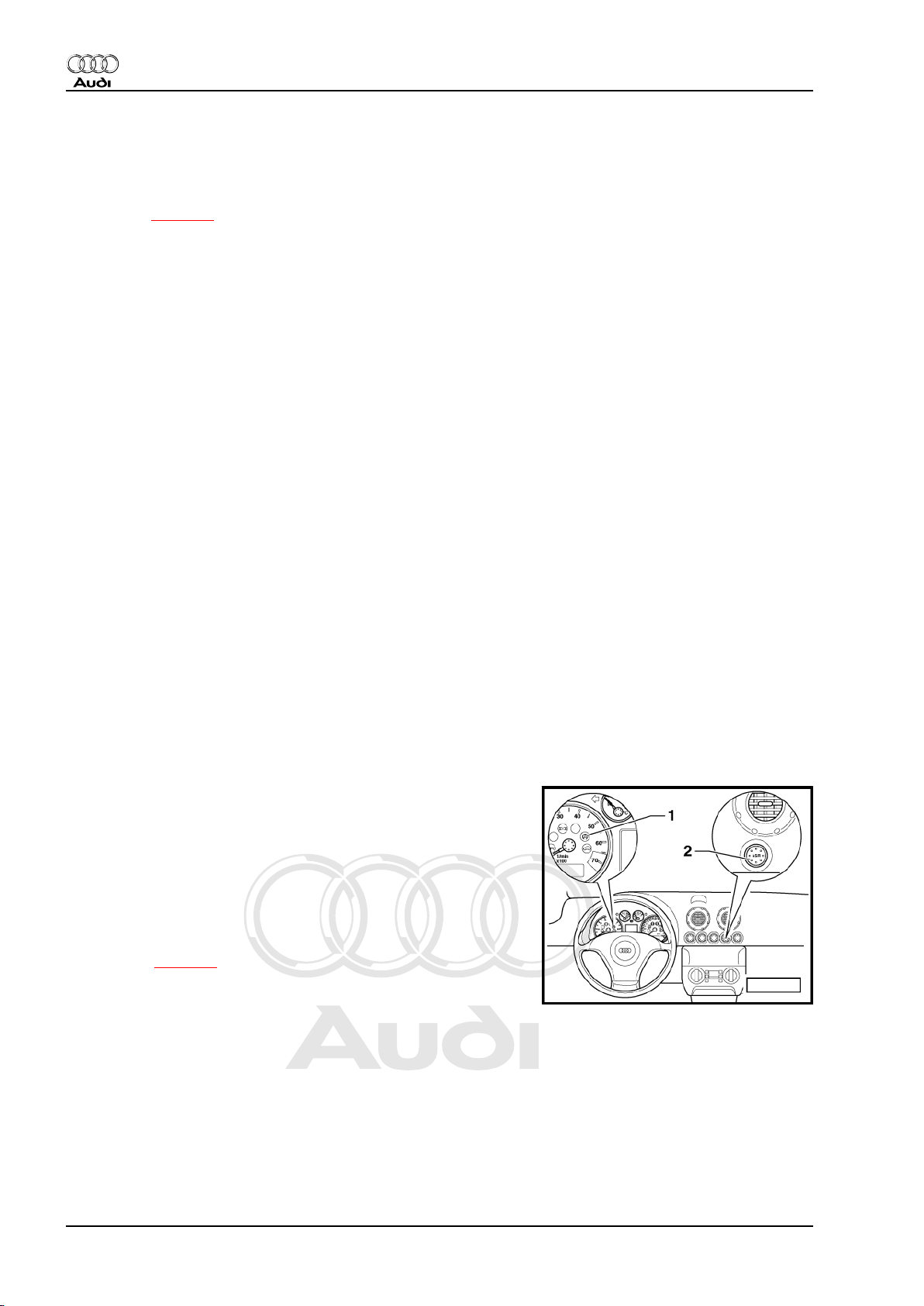
1.2.4 TCS - Traction control system
♦ TCS (traction control system) is fitted only on vehicles with
front-wheel drive. The TCS limits the engine power to prevent
the driven wheels from spinning under acceleration. The sys‐
tem operates by reducing engine torque and is active at all
speeds. The EDL and TCS functions act together to assist ac‐
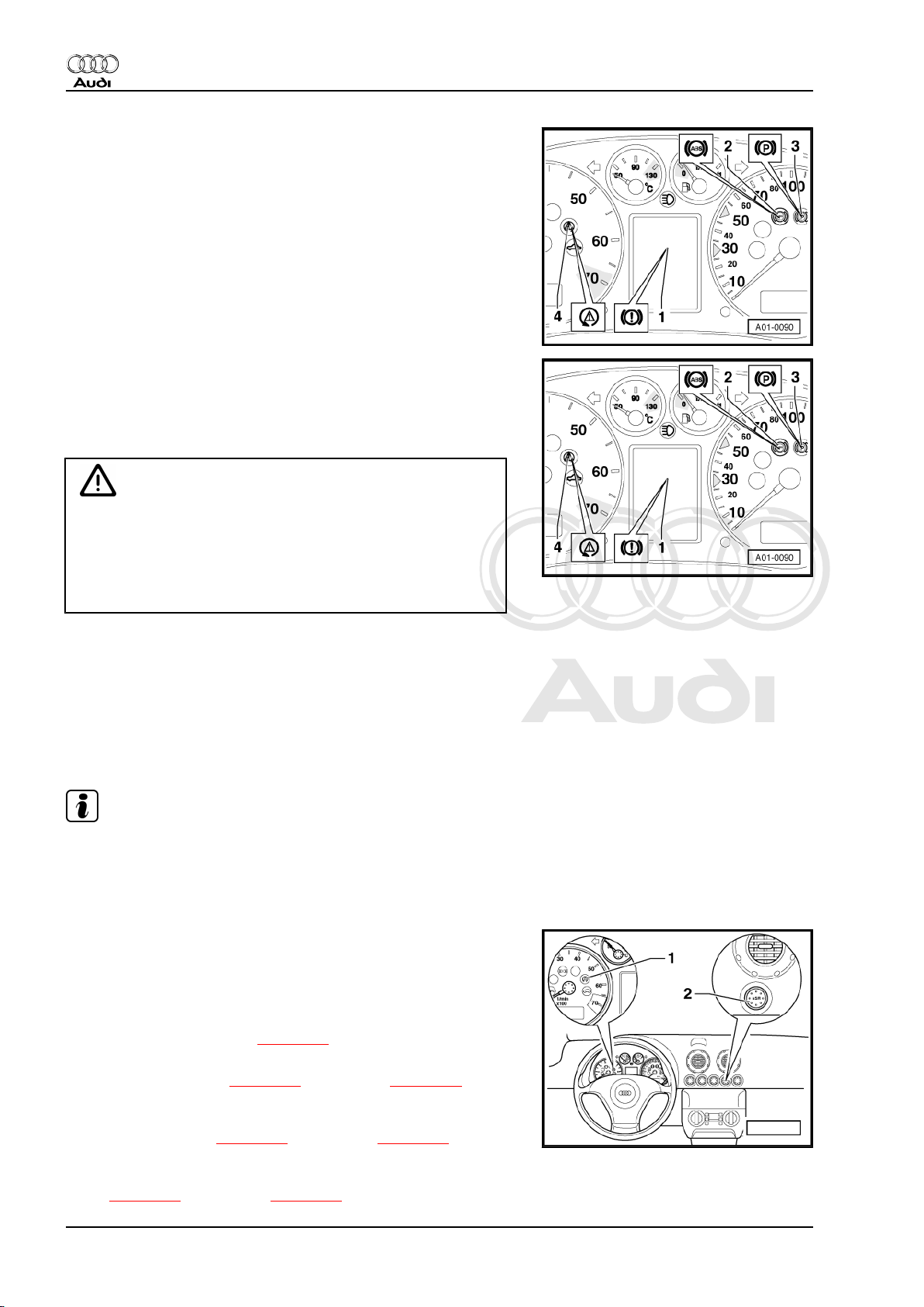
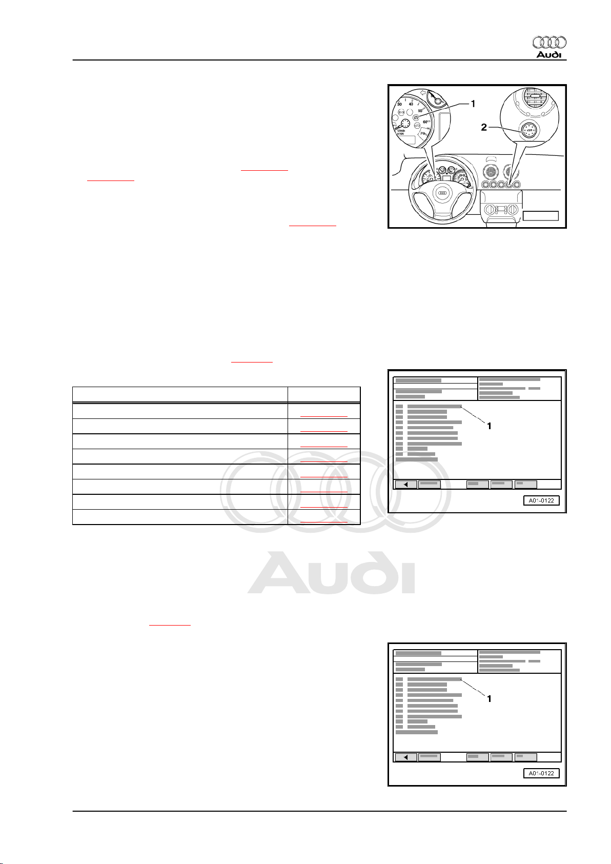
celeration. The warning lamp -1- flashes at a rate of three
times per second when the control function is working.
♦ The TCS requires an exchange of data between ABS with EDL
control unit -J104- and the engine control unit. The control
units communicate with each other. The data is transmitted via
CAN bus ⇒ page 9 .
♦ Depending on the engine version, the TCS also incorporates
an engine braking control (EBC). EBC prevents the driven
wheels from locking up due to excessive engine braking tor‐
que, for instance when the driver changes down from 3rd to
2nd gear. The engine braking effect is reduced via the elec‐
tronic idling stabilisation control.
♦ If required, the TCS function can be switched off (and on
again) by means of the button -2- (marked ASR) in the centre
of the dash panel. The TCS button has no influence on EBC.
The warning lamp lights up when the TCS is switched off. The
TCS is re-activated when the ignition is switched on again.
2 Rep. Gr.01 - Self-diagnosis, electrical checks
Page 7
Protected by copyright. Copying for private or commercial purposes, in part or in whole, is not
permitted unless authorised by AUDI AG. AUDI AG does not guarantee or accept any liability
with respect to the correctness of information in this document. Copyright by AUDI AG.
Running gear, self-diagnosis - Edition 07.2004
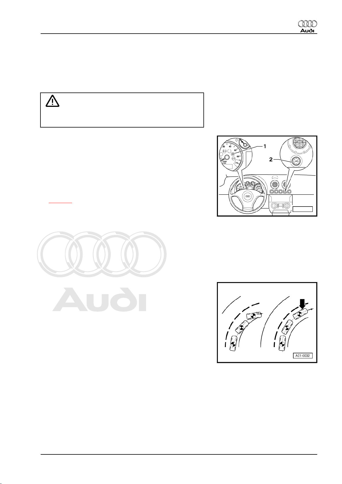
1.2.5 ESP - Electronic Stabilisation Program
The ESP is based on the existing on-board safety systems ABS/
EDL and ABS/EDL/TCS, with a number of additional capabilities.
ESP enhances the degree of control in critical dynamic condi‐
tions. In addition to the existing safety systems, ESP further
reduces the risk of skidding and improves steerability.
Caution
However, ESP is not able to overcome the physical limits of
the available road adhesion.
♦ The ESP is designed to stabilise the dynamic handling re‐
sponse of the vehicle by counteracting any tendency towards
oversteer or understeer. The functions of EBPD, ABS, EDL
and TCS are incorporated in the control system. However, the
characteristic function of the ESP is controlled brake applica‐
tion at individual wheels.
♦ The ESP function relies on an exchange of signals between
ABS with EDL control unit -J104- and the engine control unit,
the steering angle sender -G85- and the four-wheel drive con‐
trol unit -J492- (if fitted). The data is transmitted via CAN bus
⇒ page 9 .
♦ If required, the TCS function and the ESP function can be
switched off (and on again) by means of the button -2- (marked
ASR) in the dash panel. The control unit ignores the position
of the ESP switch when the driver presses the brake pedal.
ESP will remain active at all times during braking. Both func‐
tions, TCS and ESP, will be activated again automatically the
next time the ignition is switched on.
♦ When the TCS and ESP function are deactivated, the ESP and
TCS warning lamp -K155- -item 1- in the instrument cluster
lights up. The warning lamp flashes at a rate of three times per
second when the control function is actually working.
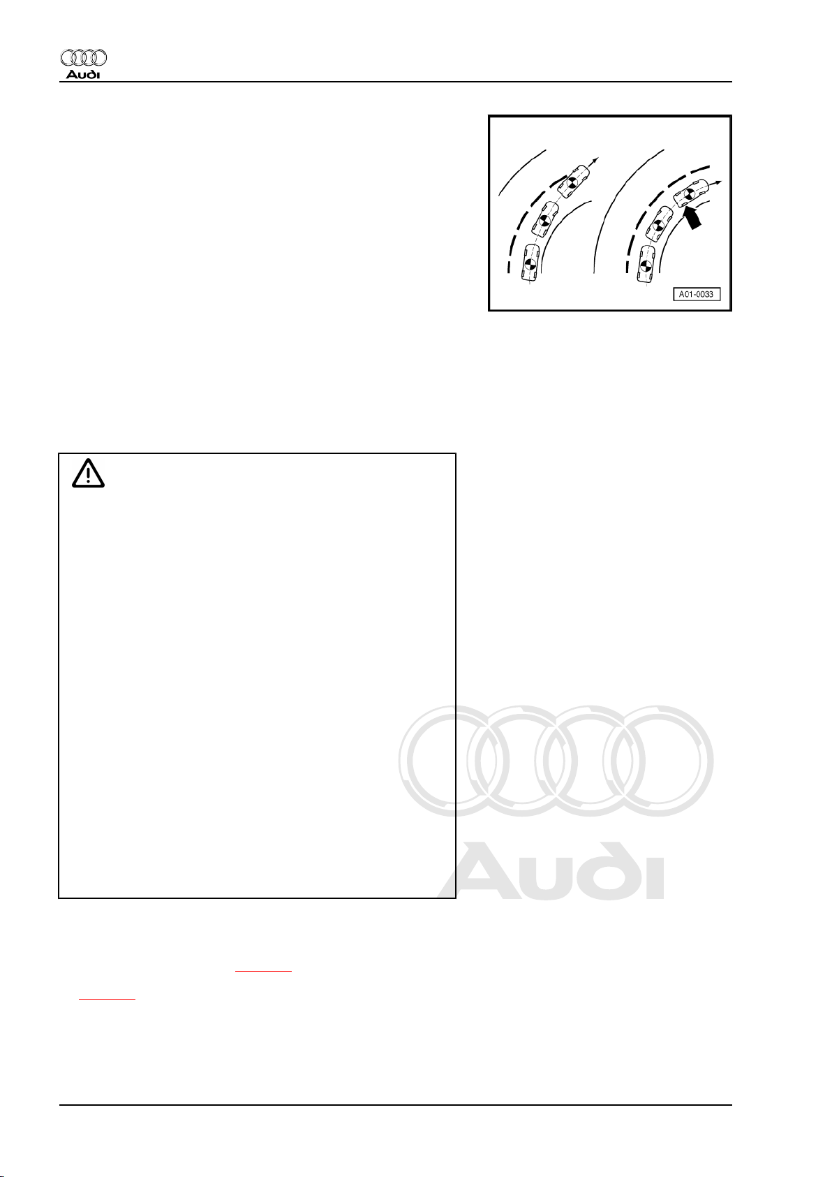
Audi TT 1999 ➤
Examples:
In an oversteer condition, the rear of the vehicle tends to break
away. The vehicle rotates further about its vertical axis than is
required to maintain course through the corner. The system coun‐
teracts this moment of vehicle oversteer by applying a controlled
braking force at the outside front wheel -arrow-.
1. Self-diagnosis 3
Page 8
Protected by copyright. Copying for private or commercial purposes, in part or in whole, is not
permitted unless authorised by AUDI AG. AUDI AG does not guarantee or accept any liability
with respect to the correctness of information in this document. Copyright by AUDI AG.
Audi TT 1999 ➤
Running gear, self-diagnosis - Edition 07.2004
In an understeer condition the front end of the vehicle does not
follow the required corner radius. The vehicle breaks away to‐
wards the outside of the bend. The vehicle does not rotate far
enough about its vertical axis to maintain course through the cor‐
ner. The system increases the amount of rotation by applying a
controlled braking force at the inside rear wheel -arrow-.
1.3 Safety precautions
♦ The ABS/EDL/TCS and ESP are safety systems; knowledge
of the systems is essential for performing repair work
♦ Always switch off the ignition before carrying out installation
or repair work.
♦ Ensure that no brake fluid enters electrical connectors.
WARNING
♦ To avoid any risk of accident, observe the following pre‐
cautions when using test instruments while road testing
the vehicle:
Audi TT Coupé:
♦ Use only vehicle diagnostic, testing and information sys‐
tem -VAS 5051 A- or vehicle diagnosis and service infor‐
mation system -VAS 5052- to read measured value
blocks. The tester must always be secured on the rear
seat and operated from there by a second person.
♦ Due to the limited space, slide the front passenger's seat
forwards as far as it will go and (without pulling the release
lever) incline the backrest as far forwards as possible by
turning the adjuster knob. Do not operate the release lever
to tilt the backrest forward.
Audi TT Roadster:
♦ In the Audi TT Roadster, use only vehicle diagnosis and
service information system -VAS 5052- with the front pas‐
senger's airbag de-activated.
♦ Switch off the front passenger's airbag by means of the
key-operated switch in the glove box or via self-diagnosis
⇒ Body, self-diagnosis; Rep. Gr. 01 .
♦ Reactivate front passenger's airbag after testing is com‐
pleted.
♦ Do not drive the vehicle with the connector unplugged from the
control unit.
♦ During the final road test ⇒ page 6 , ensure that an ABS-
controlled brake application is performed at least once
⇒ page 4 .
1.4 Requirements for test
• When starting the self-diagnosis procedure, the vehicle must
be stationary and the ignition switched on (or engine running).
It is not possible to start self-diagnosis if the wheel speed is
4 Rep. Gr.01 - Self-diagnosis, electrical checks
Page 9
Protected by copyright. Copying for private or commercial purposes, in part or in whole, is not
permitted unless authorised by AUDI AG. AUDI AG does not guarantee or accept any liability
with respect to the correctness of information in this document. Copyright by AUDI AG.
Running gear, self-diagnosis - Edition 07.2004
above 2.75 km/h. Self-diagnosis will be terminated if road
speed exceeds 20 km/h.
• Power supply OK (min. 10.0 V).
• Fuses OK ⇒ Current flow diagrams, Electrical fault finding and
Fitting locations.
• Connector on ABS with EDL control unit -J104- correctly plug‐
ged-in (retainer is engaged).
• The tyres fitted to all wheels must be of the same (approved)
size; tyres inflated to prescribed pressure.
• Wheel speed sensors must be installed correctly ⇒ Brake
system; Rep. Gr. 45 .
• Mechanical/ hydraulic brake system components (including
brake light switch and brake lights) OK. Hydraulic connections
and pipes not leaking (visual check of hydraulic unit, brake
calipers, wheel cylinders, master brake cylinder).
• Wheel bearings and wheel bearing play OK.
• When testing the ABS/EDL/TCS and ESP systems, ensure
that the vehicle's electrics are not subjected to electromag‐
netic interference: keep the vehicle away from equipment with
a high current draw, such as electric welding units.
Audi TT 1999 ➤
1.5 Fault finding procedure
If a problem exists on the vehicle, perform the fault-finding pro‐
cedure in the following sequence:
– First switch on the ignition and observe the warning lamps.
This will give an initial indication of what to look for (vehicles
without ESP ⇒ page 14 , vehicles with ESP ⇒ page 62 ).
– Observe the test requirements detailed on ⇒ page 4 .
– Connect vehicle diagnostic, testing and information system -
VAS 5051 A- and select vehicle system “03 - Brake electron‐
ics” ⇒ page 7 .
– Check the control unit version ⇒ page 8 .
– Interrogate the fault memory (vehicles without ESP
⇒ page 17 , vehicles with ESP ⇒ page 65 ). If a fault is
present in the memory: print out the content of the fault mem‐
ory and then erase the fault memory.
– Conclude the transfer of data with the function “06 - End out‐
put”.
– Eliminate the fault using the fault tables.
– If a component is indicated as being defective, only renew it if
you are sure that the electrical wiring for that component is in
proper condition. The wiring must be able to transmit the nec‐
essary signals without interference or resistance. Check the
wiring for:
♦ Corrosion and loose contacts in the connectors and earth con‐
nections. If any of the plug contacts are bent, broken or cor‐
roded, use the wiring repair kit -VAS 1978- to fit new contacts.
♦ Open circuit in wiring or short circuit to positive/earth ⇒ Current
flow diagrams, Electrical fault finding and Fitting locations.
– Check that the connectors are plugged in correctly (with re‐
tainers engaged).
– After completing the repair, select vehicle system “03 - Brake
system” for a second time. Interrogate and erase fault mem‐
ory.
1. Self-diagnosis 5
Page 10
Protected by copyright. Copying for private or commercial purposes, in part or in whole, is not
permitted unless authorised by AUDI AG. AUDI AG does not guarantee or accept any liability
with respect to the correctness of information in this document. Copyright by AUDI AG.
Audi TT 1999 ➤
Running gear, self-diagnosis - Edition 07.2004
– Conclude the transfer of data with the function “06 - End out‐
put”.
– Switch off ignition and detach diagnostic connector.
– Perform a road test ⇒ page 6 to check the function of the
system. If any of the warning lamps light up during the road
test, repeat the fault finding procedure.
WARNING
If the connector is not plugged into the ABS with EDL control
unit -J104- when the vehicle is moving, this may result in a
spurious (non-existent) fault being registered in the fault mem‐
ory of another control unit. The function of the brake system
will be impaired. The brake pressure at the rear wheels is no
longer controlled by the electronic brake force distribution func‐
tion. This can result in excessive braking at the rear, and the
tail of the vehicle may break out unexpectedly.
Note
For information on repairing common faults, refer to ⇒ Technical
Service Handbook.
1.6 Road test
Certain faults will only be detected by the self-diagnosis when the
vehicle is moving. Perform a road test to check the function of the
system.
WARNING
♦ To avoid any risk of accident, observe the safety precau‐
tions when using test instruments while road testing the
vehicle ⇒ “1.3 Safety precautions”, page 4 .
♦ If you drive the vehicle after a fault has been detected by
the self-diagnosis bear in mind that there is a risk of acci‐
dent. The function of the brake system will be impaired.
The brake pressure at the rear wheels is no longer con‐
trolled by the electronic brake force distribution function.
This can result in excessive braking at the rear, and the
tail of the vehicle may break out unexpectedly.
♦ The ABS/ESP function is deactivated when using vehicle
diagnostic, testing and information system -VAS 5051 Ain the mode “vehicle self-diagnosis” while road testing the
vehicle. However, this is not indicated by illumination of
the warning lamps. Self-diagnosis of ABS with EDL control
unit -J104- is terminated if a road speed of 20 km/h is ex‐
ceeded.
– Maintain a speed above 60 km/h for a period of 30 seconds.
After ensuring that it is safe to do so, apply the brakes hard
enough to activate ABS-controlled braking. This can be felt
from the pulsation at the brake pedal.
1.6.1 Special feature for four-wheel drive ve‐
hicles with Haldex coupling
♦ The longitudinal acceleration sender -G251- must be deacti‐
vated when testing the brake system on test rollers (vehicles
without ESP ⇒ page 35 , vehicles with ESP ⇒ page 90 ).
6 Rep. Gr.01 - Self-diagnosis, electrical checks
Page 11
Protected by copyright. Copying for private or commercial purposes, in part or in whole, is not
permitted unless authorised by AUDI AG. AUDI AG does not guarantee or accept any liability
with respect to the correctness of information in this document. Copyright by AUDI AG.
Running gear, self-diagnosis - Edition 07.2004
♦ After completion of the check, the longitudinal acceleration
sender -G251- must be reactivated by switching the ignition
off and back on again.
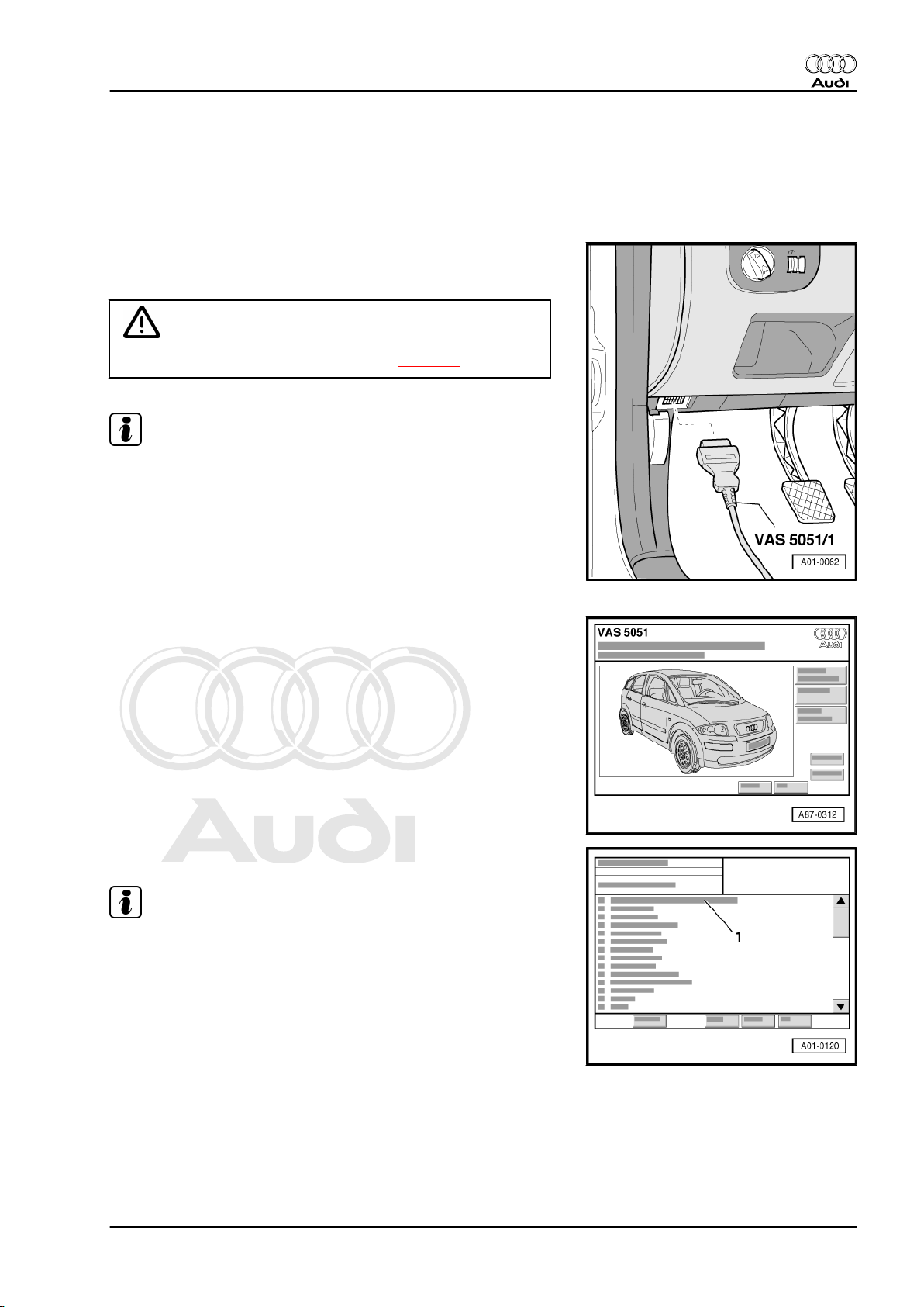
1.7 Connecting vehicle diagnostic, testing and information system -VAS 5051 A-
– With ignition switched off, connect vehicle diagnostic, testing
and information system -VAS 5051 A- with diagnosis lead VAS 5051 A/1- to diagnostic connection.
WARNING
Observe the relevant safety precautions ⇒ page 4 .
Note
Refer to ⇒ Operating instructions for vehicle diagnostic, testing
and information system -VAS 5051 A- if a fault is indicated on the
display.
Audi TT 1999 ➤
– Switch on ignition.
or
– Start engine.
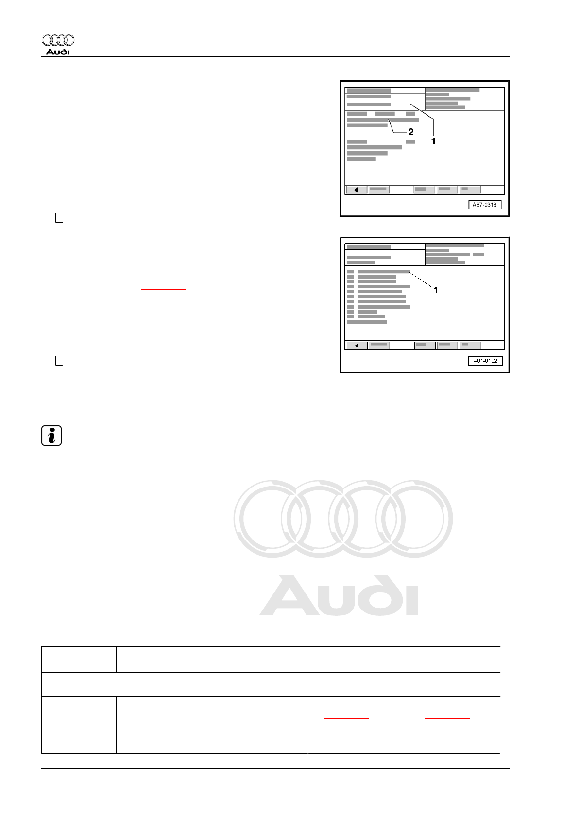
Indicated on -VAS 5051 A- :
– Touch “Vehicle self-diagnosis” key.
Indicated on -VAS 5051 A- :
Note
Touching function “00 - Interrogate fault memory - complete sys‐
tem” in list -1- implements the automatic test sequence, i.e. fault
memory interrogation takes place for all vehicle systems with selfdiagnosis capability.
– From menu -1- select vehicle system “03 - Brake electronics”.
– Wait until next readout appears.
1. Self-diagnosis 7
Page 12
Protected by copyright. Copying for private or commercial purposes, in part or in whole, is not
permitted unless authorised by AUDI AG. AUDI AG does not guarantee or accept any liability
with respect to the correctness of information in this document. Copyright by AUDI AG.
Audi TT 1999 ➤
Running gear, self-diagnosis - Edition 07.2004
Indicated on -VAS 5051 A- :
2 - Control unit identification of ABS with EDL control unit -J104- .
Control unit identification
: ABS with EDL control unit -J104- (example)
03 - Brake
Vehicle system
electronics
8N0907379.. Part No.; Allocation ⇒ Parts catalogue
ESP System designation
CAN Data bus (CAN)
Code number
241
Control unit code (checking: vehicles without
ESP ⇒ page 39 , vehicles with ESP
⇒ page 103 ).
Dealership
number 12345
Dealership identifier of -VAS 5051 A- with
which coding was last performed
If the display “vehicle system not available” appears in display
zone -1-:
– Check:
♦ Voltage supply to diagnosis connector ⇒ Current flow dia‐
grams, Electrical fault finding and Fitting locations.
♦ Wiring connection between diagnosis connector and ABS with
EDL control unit -J104- ⇒ Current flow diagrams, Electrical
fault finding and Fitting locations.
8 Rep. Gr.01 - Self-diagnosis, electrical checks
Page 13
Protected by copyright. Copying for private or commercial purposes, in part or in whole, is not
permitted unless authorised by AUDI AG. AUDI AG does not guarantee or accept any liability
with respect to the correctness of information in this document. Copyright by AUDI AG.
Running gear, self-diagnosis - Edition 07.2004
2 CAN bus
Data bus:
A data bus is a system for the transmission and distribution of
data signals.
CAN:
A Controller Area Network is a bus system working with two wires.
They are referred to as bus wires. The bus wires transmit data
signals in serial form (one after the other) to the control units con‐
nected to the system.
These control units communicate with each other (i.e. exchange
data) via the CAN bus.
2.1 Testing a “two-wire data bus system”
Special tools and workshop equipment required
♦ Vehicle diagnostic, testing and information system -VAS 5051
A-
Test sequence:
– Refer to the appropriate current flow diagram to check how
many control units are connected to the CAN bus.
– Connect vehicle diagnostic, testing and information system -
VAS 5051 A- ⇒ page 7 and select function “00 - Automatic test
sequence”. When doing this the ignition must be switched on.
– Before testing the data bus wires make sure that there are no
faults in any of the control units which are connected to the
data bus. If a fault exists, the communication with other the
control units is affected.
Note
Audi TT 1999 ➤
A fault existing in or related to one of the control units does not
affect the data bus system directly, but results from a malfunction
of some kind in one of the systems. This may be a defective sen‐
sor, for example. The result is that the sensor signal can no longer
be processed for transmission via the data bus. A malfunction of
this kind has an indirect effect on the data bus system, and will
upset the communication with other control units which require
the signal from the affected sensor.
Procedure if a fault exists:
– Rectify the fault first.
– Print out the list of faults and erase the fault memories of all
control units (refer to “Interrogating fault memory” and “Eras‐
ing fault memory” for the relevant control unit.
– Conclude the transfer of data with the function “06 - End out‐
put”.
– Rectify the faults as described in the fault tables in the relevant
Workshop Manual.
When all faults have been rectified:
– If communication between the control units is still not working
properly, test the data bus wires.
– Distinguish between two possible configurations when tracing
faults in the bus wires.
2. CAN bus 9
Page 14
Protected by copyright. Copying for private or commercial purposes, in part or in whole, is not
permitted unless authorised by AUDI AG. AUDI AG does not guarantee or accept any liability
with respect to the correctness of information in this document. Copyright by AUDI AG.
Audi TT 1999 ➤
Running gear, self-diagnosis - Edition 07.2004
♦ Two control units communicating via a “Two-line bus system”
⇒ page 10 .
♦ Three or more control units communicating via a “Two-line bus
system” ⇒ page 11 .
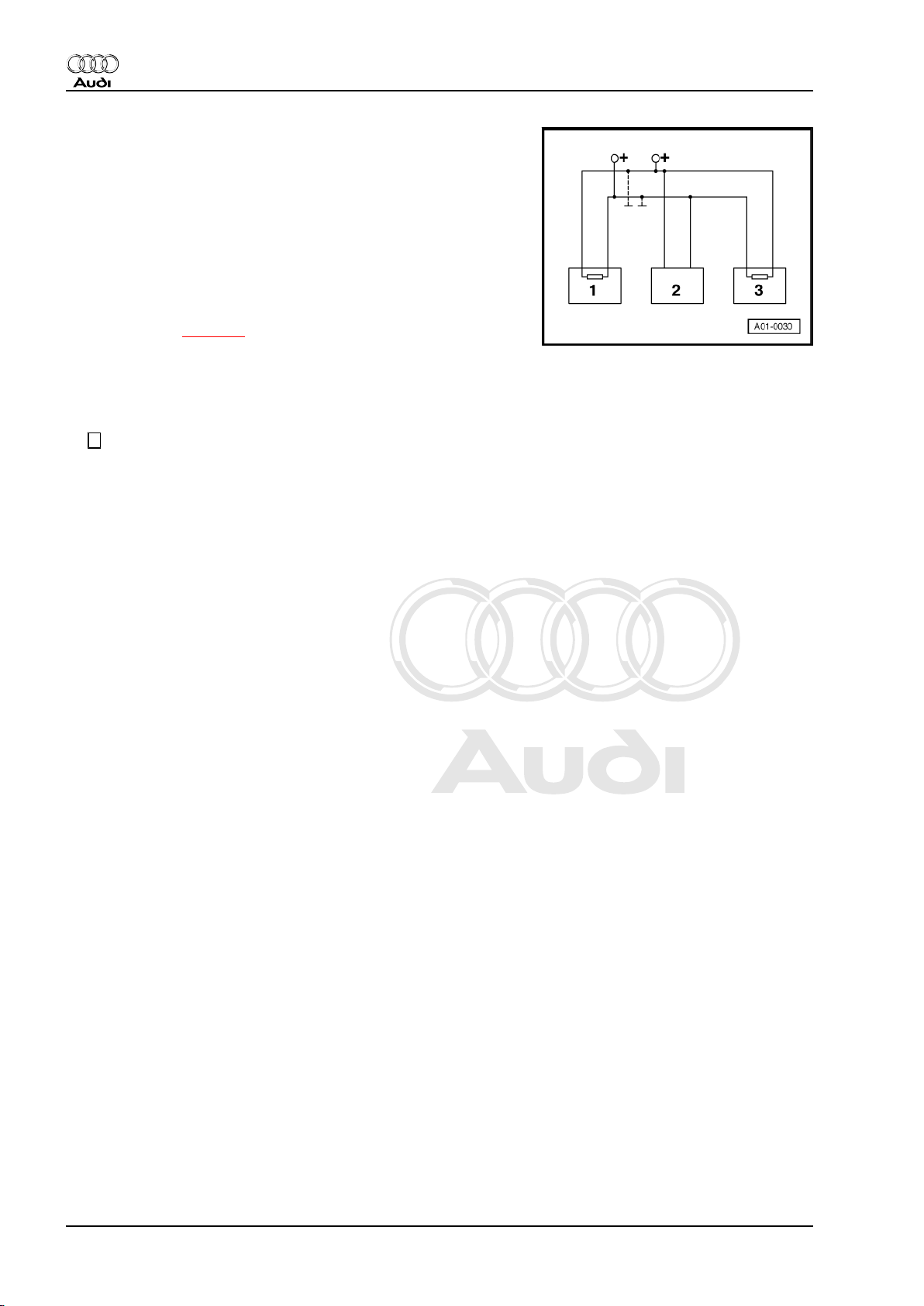
2.1.1 Two control units communicating via a
“Two-line bus system”.
– Switch off ignition.
– Unplug multi-pin connectors at both control units.
– Check for an open circuit in the bus wires ⇒ Current flow dia‐
grams, Electrical fault finding and Fitting locations.
– Check for short circuit between the bus wires ⇒ Current flow
diagrams, Electrical fault finding and Fitting locations.
– Check for short to positive and short to earth in the bus wires.
If the cause of the fault cannot be found in the data bus wires:
– As a trial measure, renew the control unit which can be ex‐
changed with the least effort in terms of time and cost.
If the control unit communication via data bus is still not OK:
– Renew the second control unit.
10 Rep. Gr.01 - Self-diagnosis, electrical checks
Page 15
Protected by copyright. Copying for private or commercial purposes, in part or in whole, is not
permitted unless authorised by AUDI AG. AUDI AG does not guarantee or accept any liability
with respect to the correctness of information in this document. Copyright by AUDI AG.
Running gear, self-diagnosis - Edition 07.2004
2.1.2 Three or more control units communi‐
cating via a “Two-line bus system”.
Example 1:
The faults stored in the fault memories indicate that the control
unit -1- has no connection to control units -2- and -3-.
Control unit Faults stored in fault memory
-1- ♦ No message from control unit -2-
♦ No message from control unit -3-
-2- ♦ No message from control unit -1-
-3- ♦ No message from control unit -1-
– Switch off ignition.
– Unplug electrical connectors on control units linked by data
bus wires and check bus wires for open circuit ⇒ Current flow
diagrams, Electrical fault finding and Fitting locations.
Audi TT 1999 ➤
Example 2:
The faults stored in the fault memories indicate that the control
unit -2- does not communicate with control units -1- and -3-.
Control unit Faults stored in fault memory
-1- ♦ No message from control unit -2-
-2- ♦ No message from control unit -1-
♦ No message from control unit -3-
-3- ♦ No message from control unit -2-
– Switch off ignition.
– Unplug electrical connectors on control units linked by data
bus wires and check bus wires for open circuit ⇒ Current flow
diagrams, Electrical fault finding and Fitting locations.
Example 3:
The faults stored in the fault memories indicate that none of the
control units can transmit or receive.
Control unit Faults stored in fault memory
-1- ♦ Control unit defective
-2- ♦ Control unit defective
-3- ♦ Control unit defective
– Switch off ignition.
– Unplug electrical connectors on control units linked by data
bus wires and check bus wires for short circuit ⇒ Current flow
diagrams, Electrical fault finding and Fitting locations.
2. CAN bus 11
Page 16
Protected by copyright. Copying for private or commercial purposes, in part or in whole, is not
permitted unless authorised by AUDI AG. AUDI AG does not guarantee or accept any liability
with respect to the correctness of information in this document. Copyright by AUDI AG.
Audi TT 1999 ➤
Running gear, self-diagnosis - Edition 07.2004
– Check the bus wires for short to positive and short to earth.
– If the cause of the fault “Control unit defective” cannot be found
in the data bus wires, check whether one of the control units
is responsible for causing the fault.
• Electrical connectors on all control unit that communicate via
the CAN data bus are unplugged.
• Ignition switched off
– Connect one of the control units.
– Connect vehicle diagnostic, testing and information system -
VAS 5051 A- ⇒ page 7 .
– Switch on ignition and select the relevant vehicle system.
– Interrogate and erase the fault memory of the control unit
which has been just connected.
– Terminate function “05 - Erasing fault memory” by touching
← key.
– Conclude the transfer of data with the function “06 - End out‐
put”.
– Switch the ignition off and then on again.
– Leave the ignition switched on for 10 seconds. Then interrog‐
ate the fault memory of the control unit that has just been
connected.
If the fault “control unit defective” is indicated:
– Renew the control unit which has just been connected.
If the fault “control unit defective” is not indicated:
– Connect the next control unit and repeat the procedure.
12 Rep. Gr.01 - Self-diagnosis, electrical checks
Page 17
Protected by copyright. Copying for private or commercial purposes, in part or in whole, is not
permitted unless authorised by AUDI AG. AUDI AG does not guarantee or accept any liability
with respect to the correctness of information in this document. Copyright by AUDI AG.
Running gear, self-diagnosis - Edition 07.2004
3 ABS/EDL and ABS/EDL/TCS, ITT
Mark 20 without ESP
♦ The Audi TT without ESP is equipped with the ABS/EDL ITT
Mark 20 system or the ABS/EDL/TCS ITT Mark 20 system.
♦ The data signals are transmitted via CAN bus.
Note
ESP may have been retrofitted by AUDI AG on vehicles not orig‐
inally equipped with this system ⇒ page 59 .
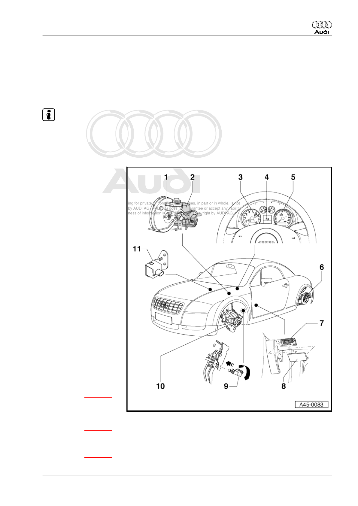
3.1 Electrical/electronic components and fitting locations
1 - Brake master cylinder and
brake servo
2 - Hydraulic control unit
❑ The hydraulic control
unit comprises the ABS
hydraulic pump -V64- ,
the ABS hydraulic unit N55- and the ABS with
EDL control unit -J104- .
❑ Fitting location: in en‐
gine compartment (leftside)
❑ Tested by self-diagno‐
❑ Only unplug 25-pin con‐
❑ Assignment of 25-pin
❑ Removing and installing
❑ Perform coding of ABS
3 - Traction control system
warning lamp -K86-
❑ Only on vehicles with
❑ Fitting location: in instru‐
❑ Function ⇒ page 14
4 - “Brake warning” symbol
❑ Appears in the display of
❑ Function ⇒ page 14
5 - ABS warning lamp -K47-
❑ Fitting location: in instrument cluster
❑ Function ⇒ page 14
sis
nector when the ignition
is switched off
connector ⇒ page 50
⇒ Brake system; Rep.
Gr. 45
with EDL control unit J104- after renewal
⇒ page 39
TCS
ment cluster
the driver information system
Audi TT 1999 ➤
3. ABS/EDL and ABS/EDL/TCS, ITT Mark 20 without ESP 13
Page 18
Protected by copyright. Copying for private or commercial purposes, in part or in whole, is not
permitted unless authorised by AUDI AG. AUDI AG does not guarantee or accept any liability
with respect to the correctness of information in this document. Copyright by AUDI AG.
Audi TT 1999 ➤
Running gear, self-diagnosis - Edition 07.2004
6 - Rear left and rear right speed sensor and speed sensor rotor
❑ Rear left speed sensor -G46- and rear right speed sensor -G44❑ Removing and installing speed sensor, fitting speed sensor wires ⇒ Brake system; Rep. Gr. 45
❑ Checking speed sensor rotor ⇒ Brake system; Rep. Gr. 45
❑ Speed sensor rotor is welded to wheel hub; removing and installing wheel hub ⇒ Running gear, front-
wheel drive and four-wheel drive; Rep. Gr. 42
7 - Diagnosis connector
❑ Fitting location: in footwell (front left), next to release lever for bonnet.
8 - Diagnostics connection cover
9 - Brake light switch -F-
❑ Can be checked via reading measured value block ⇒ page 45
❑ Removing and installing ⇒ Brake system; Rep. Gr. 45
10 - Front left and front right speed sensor and speed sensor rotor
❑ Front left speed sensor -G47- and front right speed sensor -G45❑ Removing and installing speed sensor, fitting speed sensor wires ⇒ Brake system; Rep. Gr. 45
❑ Checking speed sensor rotor ⇒ Brake system; Rep. Gr. 45
❑ Speed sensor rotor is welded to wheel hub; removing and installing wheel hub ⇒ Running gear, front-
wheel drive and four-wheel drive; Rep. Gr. 40
11 - Longitudinal acceleration sender -G251-
❑ Four-wheel drive vehicles only
❑ Fitting location: on A-pillar (passenger side)
❑ Can be checked via reading measured value block ⇒ page 46
❑ Refer to ⇒ Brake system; Rep. Gr. 45 for removing and installing, then perform zero compensation in
basic setting ⇒ page 36
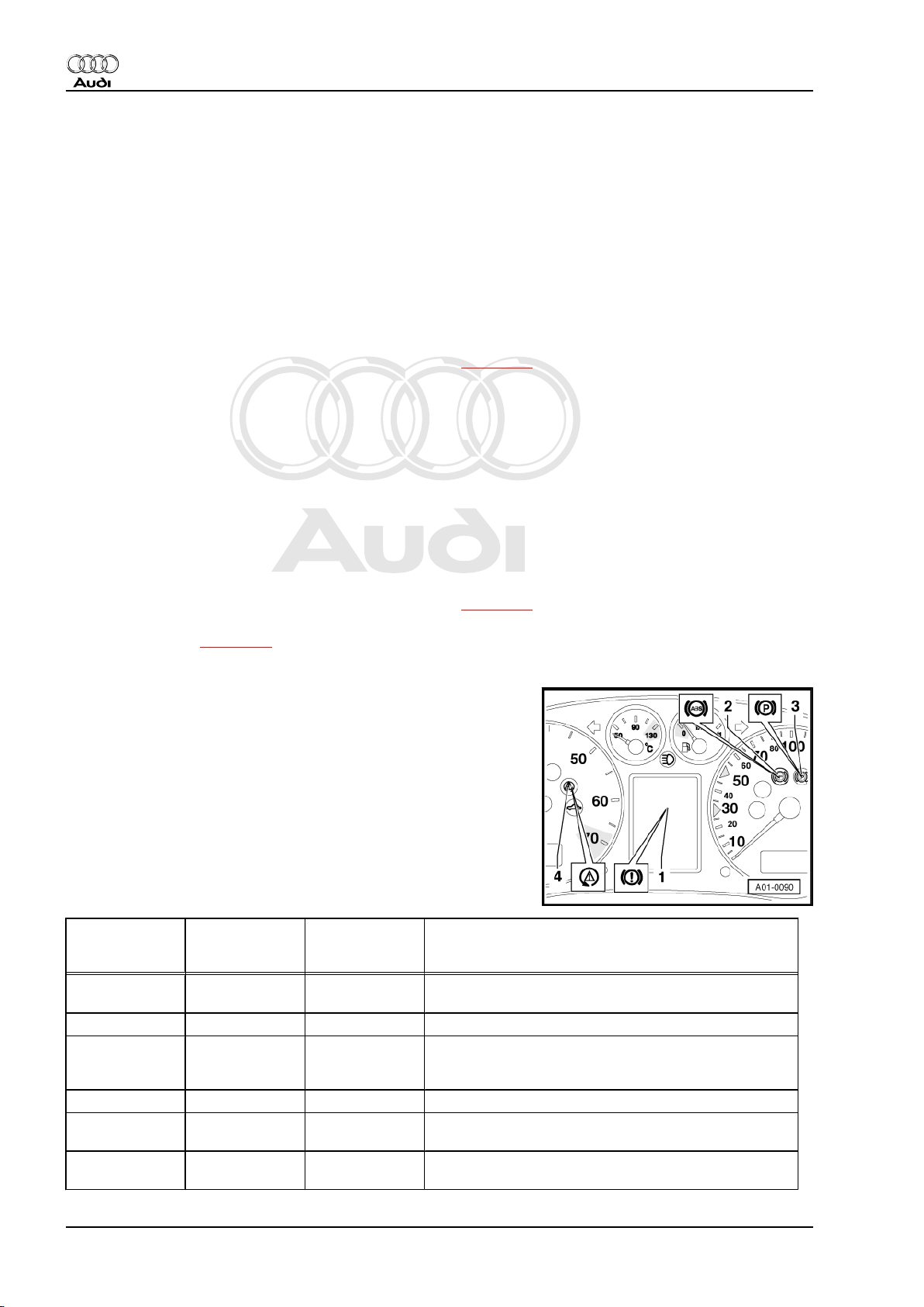
3.2 Faults displayed by warning lamps in in‐
strument cluster
1 - “Brake warning” symbol
2 - ABS warning lamp -K47-
3 - Handbrake warning lamp -K14-
4 - Traction control system warning lamp -K86- (only on vehi‐
cles with TCS)
“Brake warning”
symbol
On On On Test sequence after switching on ignition (first two sec‐
Off Off Off System OK (2 seconds after switching on ignition)
Off Off On TCS system failure or TCS system has been switched
Off Off flashes TCS control function is operating
Off On On ABS/EDL/TCS system failure (e.g. wheel speed sen‐
On On On ABS/EDL/TCS/EBPD system failure (e.g. several
ABS warning
lamp -K47-
Traction control
system warning
lamp -K86-
1)
Explanation
onds).
off via button; ABS, EDL and EBPD systems remain
functional.
sor defective), the EBPD remains fully functional.
wheel speed sensors defective)
14 Rep. Gr.01 - Self-diagnosis, electrical checks
Page 19
Protected by copyright. Copying for private or commercial purposes, in part or in whole, is not
permitted unless authorised by AUDI AG. AUDI AG does not guarantee or accept any liability
with respect to the correctness of information in this document. Copyright by AUDI AG.
Audi TT 1999 ➤
Running gear, self-diagnosis - Edition 07.2004
“Brake warning”
symbol
ABS warning
lamp -K47-
Traction control
system warning
lamp -K86-
1)
Explanation
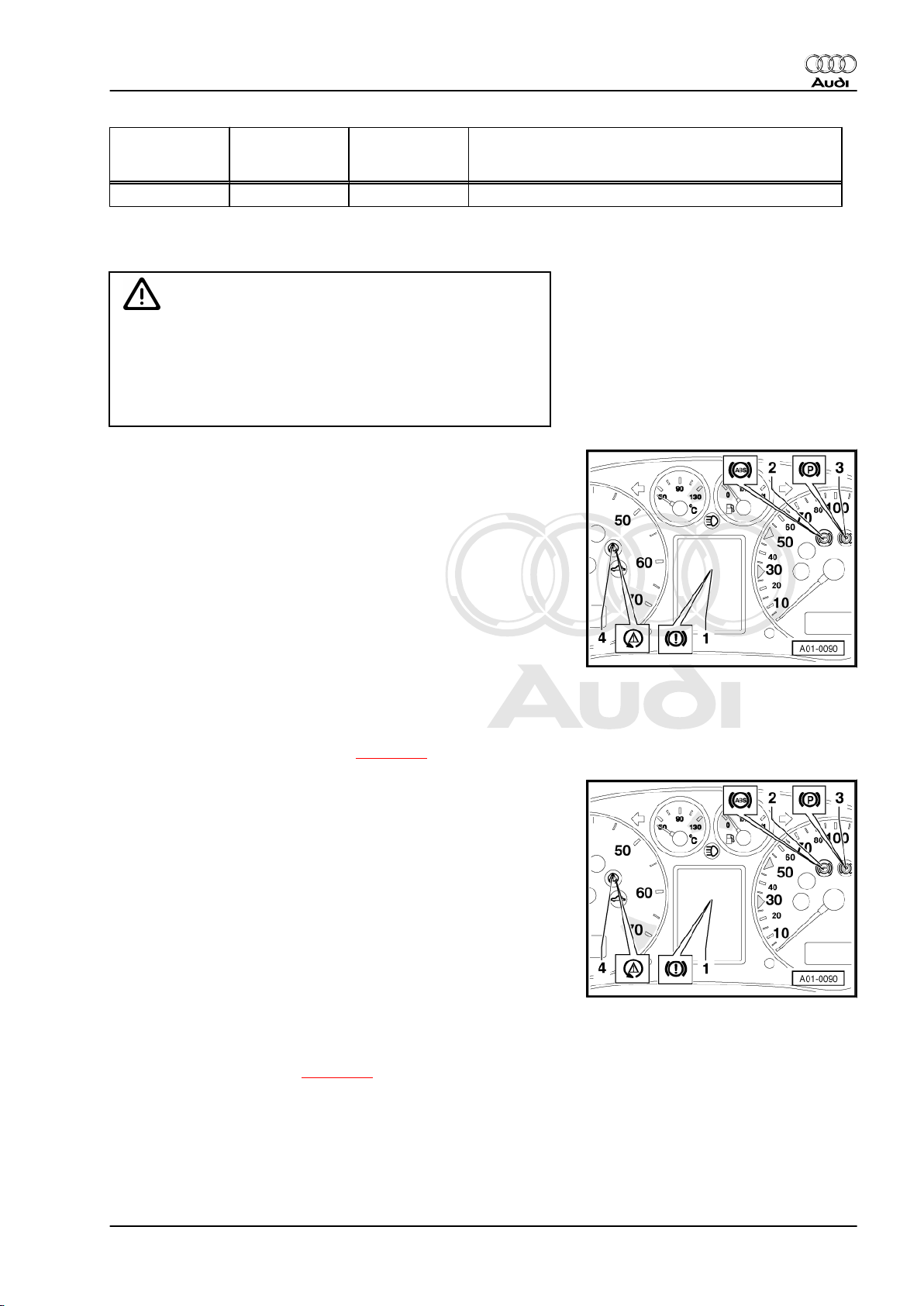
On Off Off Brake fluid level too low; all systems remain functional
1) Only on vehicles with TCS system
WARNING
There is a risk of accident if the ABS warning lamp -K47- and
the “brake warning symbol” both light up. The function of the
brake system will be impaired. As the brake pressure is no
longer controlled by the electronic brake force distribution the
rear wheels tend to brake excessively. Due to this the rear of
the vehicle may break away unexpectedly.
The ABS warning lamp -K47- -item 2- lights up during the test
sequence (self-test)
The system runs through an automatic test sequence when the
ignition is switched on: the ABS warning lamp -K47- is activated
by the ABS with EDL control unit -J104- and lights up for 2 sec‐
onds. During this period the control unit tests the following func‐
tions via self-test.
♦ The voltage supply is checked (min. 10.0 Volt).
♦ The control unit including the valve windings is checked.
♦ A speed sensor check (electrical test) is carried out; this is only
completed at 20 km/h.
♦ Control unit code is checked.
If the system does not perform the test sequence:
– Check voltage supply of ABS with EDL control unit -J104-
(perform electrical check, step 3 ⇒ page 51 ).
The ABS warning lamp -K47- -item 2- stays on after the test se‐
quence is completed
If a fault affecting only the anti-lock brake system is detected by
self-diagnosis, the ABS is switched off. The conventional brake
system remains fully functional.
The causes of the fault may be as follows:
♦ Voltage supply is below 10 Volts.
♦ A fault exists which affects only the ABS.
♦ A sensor fault has occurred after the last start (sporadic fault).
In this case the ABS warning lamp goes out automatically after
the vehicle is started again and the road speed exceeds 20 km/
h.
♦ Connection between ABS with EDL control unit -J104- and in‐
strument cluster is faulty or instrument cluster faulty (perform
electrical check, step 14 ⇒ page 55 ).
3. ABS/EDL and ABS/EDL/TCS, ITT Mark 20 without ESP 15
Page 20
Protected by copyright. Copying for private or commercial purposes, in part or in whole, is not
permitted unless authorised by AUDI AG. AUDI AG does not guarantee or accept any liability
with respect to the correctness of information in this document. Copyright by AUDI AG.
Audi TT 1999 ➤
Running gear, self-diagnosis - Edition 07.2004
The ABS warning lamp -K47- -item 2- goes out after the test se‐
quence is completed,, but “brake warning symbol” -1- remains on
All systems remain functional.
The causes of the fault may be as follows:
♦ Brake fluid level too low.
♦ Fault in instrument cluster ⇒ Electrical system, self-diagnosis;
Rep. Gr. 01 or ⇒ Current flow diagrams, Electrical fault finding
and Fitting locations.
The ABS warning lamp -K47- -item 2- stays on after the test se‐
quence is completed and “brake warning symbol” -1- lights up
when vehicle speed first exceeds 10 km/h or engine speed first
exceeds 2000 rpm
The ABS system is defective and the EBPD system deactivated.
WARNING
There is a risk of accident if the ABS warning lamp -K47- and
the “brake warning symbol” both light up.The function of the
brake system will be impaired. As the brake pressure is no
longer controlled by the electronic brake force distribution the
rear wheels tend to brake excessively.Due to this the rear of
the vehicle may break away unexpectedly.
The causes of the fault may be as follows:
♦ The control unit is not coded (Code 00000), or is incorrectly
coded. In this case the ABS warning lamp -K47- will flash at a
rate of once per second. The “brake warning” symbol will also
flash when vehicle speed first exceeds 10 km/h or engine
speed first exceeds 2000 rpm after the ignition is switched on.
♦ A fault exists which affects the ABS and EBPD.
Note
If the ABS warning lamp -K47- and the “brake warning” symbol
do not light up but the brake system is not fully functional, the fault
must be traced in the conventional brake system ⇒ Brake system;
Rep. Gr. 46 and ⇒ Brake system; Rep. Gr. 47 .
Traction control system warning lamp -K86- -item 1- does not light
up after TCS is deactivated by pressing the traction control sys‐
tem switch -E132- -item 2-.
The causes of the fault may be as follows:
♦ Traction control system warning lamp -K86- defective (perform
electrical check, step 17 ⇒ page 57 ).
♦ Traction control system switch -E132- defective (perform elec‐
trical check, step 17 ⇒ page 57 and step 18 ⇒ page 57 ).
♦ Open circuit in vehicle power supply and wiring from ABS with
EDL control unit -J104- to instrument cluster (perform electri‐
cal check, step 17 ⇒ page 57 and step 18 ⇒ page 57 .
♦ Short circuit to positive in wiring from ABS with EDL control
unit -J104- to instrument cluster (perform electrical check, step
17 ⇒ page 57 and step 18 ⇒ page 57 ).
16 Rep. Gr.01 - Self-diagnosis, electrical checks
Page 21
Protected by copyright. Copying for private or commercial purposes, in part or in whole, is not
permitted unless authorised by AUDI AG. AUDI AG does not guarantee or accept any liability
with respect to the correctness of information in this document. Copyright by AUDI AG.
Running gear, self-diagnosis - Edition 07.2004
Traction control system warning lamp -K86- lights continuously
after ignition is switched on, and none of the malfunctions above
occur
The cause of the fault may be as follows:
♦ Short circuit to earth in wiring from ABS with EDL control unit
-J104- to instrument cluster (activation of TCS warning lamp)
(perform electrical check, step 17 ⇒ page 57 and step 18
⇒ page 57 ).
Vehicle with ABS/EDL has no EDL function
A possible cause of this fault is that the brake light switch is not
functioning. Check “measured value block 003” ⇒ page 45 .
Renewing brake light switch ⇒ Brake system; Rep. Gr. 45 .
3.3 Performing self-diagnosis on the ABS/ EDL and ABS/EDL/TCS, ITT Mark 20 without ESP
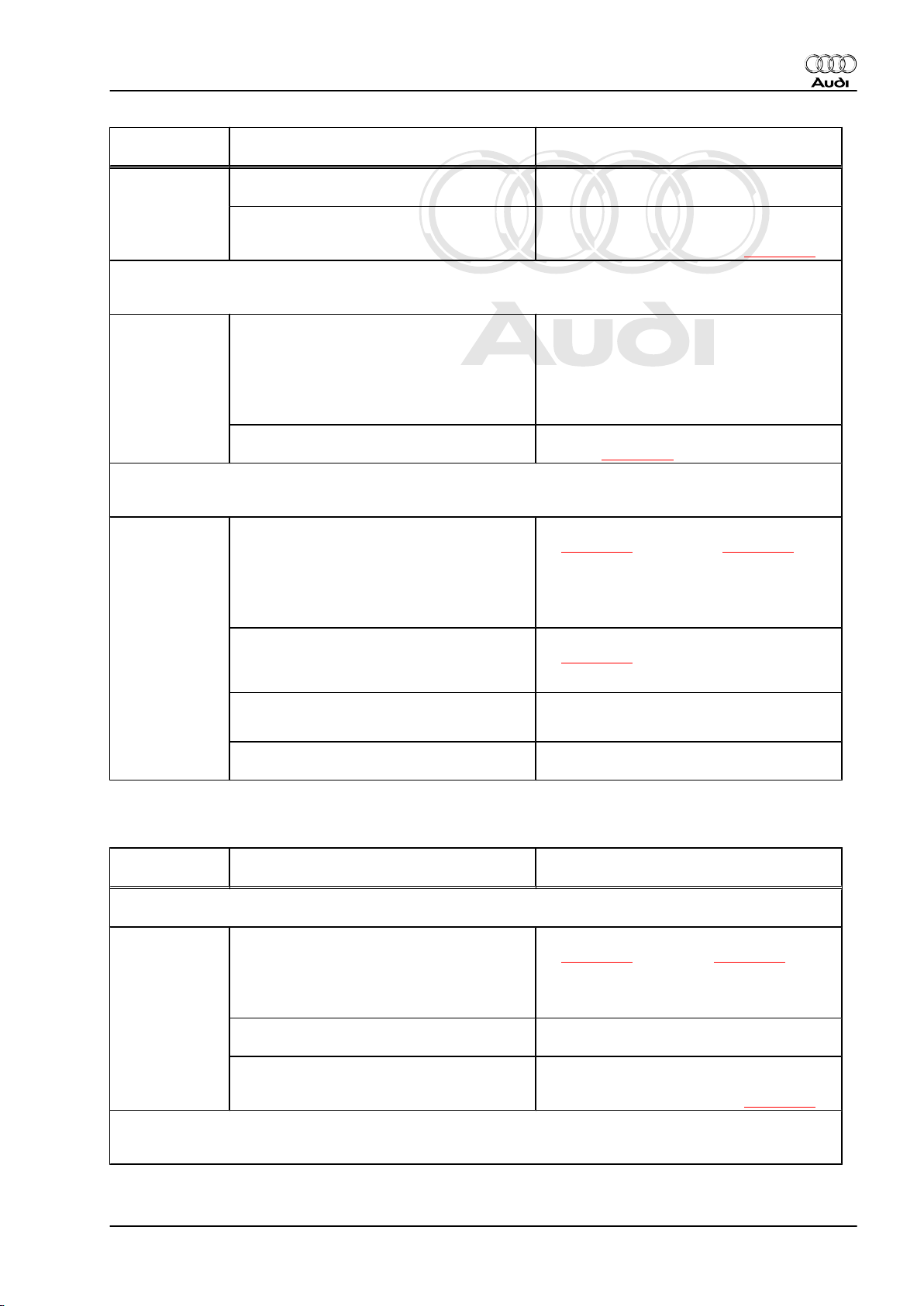
List of available functions
– With ignition switched off, connect vehicle diagnostic, testing
and information system -VAS 5051 A- with diagnosis lead VAS 5051 A/1- to diagnosis connector and select vehicle
system “03 - Brake electronics” ⇒ page 7 .
The following functions are available from the list -1-:
Audi TT 1999 ➤
Functions Page
02 Interrogate fault memory ⇒ page 17
03 Final control diagnosis ⇒ page 25
04 Basic setting ⇒ page 32
05 Erase fault memory ⇒ page 38
06 End output ⇒ page 39
07 Code control unit ⇒ page 39
08 Read measured value block ⇒ page 42
11
Login procedure/encoding II
2) The login procedure/encoding II is only required on four-wheel drive vehicles.
2)
⇒ page 46
The other functions displayed are currently not available, or can
be disregarded.
3.4 Interrogating fault memory
– Connect vehicle diagnostic, testing and information system -
VAS 5051 A- ⇒ page 7 and select vehicle system “03 - Brake
electronics”. When doing this the ignition must be switched on.
Indicated on -VAS 5051 A- :
– From list -1- select function “02 - Interrogate fault memory”.
3. ABS/EDL and ABS/EDL/TCS, ITT Mark 20 without ESP 17
Page 22
Protected by copyright. Copying for private or commercial purposes, in part or in whole, is not
permitted unless authorised by AUDI AG. AUDI AG does not guarantee or accept any liability
with respect to the correctness of information in this document. Copyright by AUDI AG.
Audi TT 1999 ➤
Running gear, self-diagnosis - Edition 07.2004
Indicated on -VAS 5051 A- :
-1- Content of fault memory No faults detected
or
X faults detected
-2- Fault Fault code
Fault location
Type of fault
A - If a fault was detected:
– Print out information on screen or self-diagnosis log.
– Terminate function “02 - Interrogate fault memory” by touching
← key.
Indicated on -VAS 5051 A- :
– Rectify fault(s) according to fault tables ⇒ page 18 .
– From list -1- select function “02 - Interrogate fault memory” and
erase fault memory ⇒ page 38 .
– From list -1- select function “06 - End output” ⇒ page 39 .
– Perform road test and interrogate fault memory again.
B - If no fault was detected:
– Terminate function “02 - Interrogate fault memory” by touching
← key.
– Select function “06 - End output” from list ⇒ page 39 .
3.5 Fault tables
Note
♦
The following table includes all faults which can be detected
by the ABS with EDL control unit -J104- and displayed by VAS 5051 A- when interrogating the fault memory.
♦
The contents of the fault memory remains stored until the
memory is erased; Erasing fault memory ⇒ page 38 .
♦
Faults are listed according to a 5-digit fault code, which ap‐
pears in the left-hand column of the fault table.
♦
Sporadic (intermittent) faults are identified as such by the word
“sporadic” appearing on the display.
♦
Check wiring and connectors going to the relevant compo‐
nents according to current flow diagram before renewing com‐
ponents indicated as faulty by -VAS 5051 A- . Also check earth
connections according to current flow diagram. This is partic‐
ularly important if faults are indicated as being “sporadic”.
Fault 00283
Display on -
VAS 5051 A-
00283
Front left speed sensor -G47-
♦ Open circuit, loose contact or short to
Possible cause of fault Fault remedy
positive or earth in speed sensor wire or
speed sensor
– Perform electrical check, step 6
⇒ page 52 and step 10 ⇒ page 54
♦ Speed sensor winding defective
18 Rep. Gr.01 - Self-diagnosis, electrical checks
Page 23
Protected by copyright. Copying for private or commercial purposes, in part or in whole, is not
permitted unless authorised by AUDI AG. AUDI AG does not guarantee or accept any liability
with respect to the correctness of information in this document. Copyright by AUDI AG.
Audi TT 1999 ➤
Running gear, self-diagnosis - Edition 07.2004
Display on -
VAS 5051 A-
♦ Speed sensor or rotor damaged – Check speed sensor and rotor ⇒ Brake
♦ ABS with EDL control unit -J104- defec‐
tive
00283
Front left speed sensor -G47Mechanical fault
• This fault is
only detec‐
♦ Excessive air gap between speed sensor
and rotor.
ted above 20
km/h (carry
out test
drive).
♦ Outlet valves in hydraulic unit defective – Check hydraulic unit in final control diag‐
00283
Front left speed sensor -G47Signal outside tolerance
• This fault is
only detec‐
ted above 20
km/h (carry
out test
♦ Open circuit, loose contact or short to
positive or earth in speed sensor wire or
speed sensor
♦ Speed sensor winding defective
drive).
♦ Electrical interference from external in‐
terference sources (high frequency radi‐
ation, e.g. non-insulated ignition cable)
Possible cause of fault Fault remedy
system; Rep. Gr. 45
– Remove hydraulic control unit, renew
control unit ⇒ Brake system; Rep. Gr.
45 , then code control unit ⇒ page 39
– Check installation of speed sensor and
rotor ⇒ Brake system; Rep. Gr. 45
nosis ⇒ page 25
– Perform electrical check, step 6
⇒ page 52 and step 10 ⇒ page 54
– Read measured value block 001
⇒ page 44
♦ Excessive air gap between speed sensor
and rotor.
♦ Speed sensor or rotor damaged – Check speed sensor and rotor ⇒ Brake
Fault 00285
Display on -
Possible cause of fault Fault remedy
VAS 5051 A-
00285
Front right speed sensor -G45-
♦ Open circuit, loose contact or short to
positive or earth in speed sensor wire or
speed sensor
♦ Speed sensor winding defective
♦ Speed sensor or rotor damaged – Check speed sensor and rotor ⇒ Brake
♦ ABS with EDL control unit -J104- defec‐
tive
00285
Front right speed sensor -G45Mechanical fault
– Check installation of speed sensor and
rotor ⇒ Brake system; Rep. Gr. 45
system; Rep. Gr. 45
– Perform electrical check, step 5
⇒ page 52 and step 9 ⇒ page 54
system; Rep. Gr. 45
– Remove hydraulic control unit, renew
control unit ⇒ Brake system; Rep. Gr.
45 , then code control unit ⇒ page 39
3. ABS/EDL and ABS/EDL/TCS, ITT Mark 20 without ESP 19
Page 24
Protected by copyright. Copying for private or commercial purposes, in part or in whole, is not
permitted unless authorised by AUDI AG. AUDI AG does not guarantee or accept any liability
with respect to the correctness of information in this document. Copyright by AUDI AG.
Audi TT 1999 ➤
Running gear, self-diagnosis - Edition 07.2004
Display on -
Possible cause of fault Fault remedy
VAS 5051 A-
• This fault is
only detec‐
♦ Excessive air gap between speed sensor
and rotor.
ted above 20
km/h (carry
out test
drive).
♦ Outlet valves in hydraulic unit defective – Check hydraulic unit in final control diag‐
00285
Front right speed sensor -G45Signal outside tolerance
• This fault is
only detec‐
ted above 20
km/h (carry
out test
♦ Open circuit, loose contact or short to
positive or earth in speed sensor wire or
speed sensor
♦ Speed sensor winding defective
drive).
♦ Electrical interference from external in‐
terference sources (high frequency radi‐
ation, e.g. non-insulated ignition cable)
♦ Excessive air gap between speed sensor
and rotor.
– Check installation of speed sensor and
rotor ⇒ Brake system; Rep. Gr. 45
nosis ⇒ page 25
– Perform electrical check, step 5
⇒ page 52 and step 9 ⇒ page 54
– Read measured value block 001
⇒ page 44
– Check installation of speed sensor and
rotor ⇒ Brake system; Rep. Gr. 45
♦ Speed sensor or rotor damaged – Check speed sensor and rotor ⇒ Brake
Fault 00287
Display on -
VAS 5051 A-
00287
Rear right speed sensor -G44-
♦ Open circuit, loose contact or short to
positive or earth in speed sensor wire or
speed sensor
♦ Speed sensor winding defective
♦ Speed sensor or rotor damaged – Check speed sensor and rotor ⇒ Brake
♦ ABS with EDL control unit -J104- defec‐
tive
00287
Rear right speed sensor -G44Mechanical fault
• This fault is
only detec‐
♦ Excessive air gap between speed sensor
and rotor.
ted above 20
km/h (carry
out test
drive).
system; Rep. Gr. 45
Possible cause of fault Fault remedy
– Perform electrical check, step 7
⇒ page 53 and step 11 ⇒ page 54
system; Rep. Gr. 45
– Remove hydraulic control unit, renew
control unit ⇒ Brake system; Rep. Gr.
45 , then code control unit ⇒ page 39
– Check installation of speed sensor and
rotor ⇒ Brake system; Rep. Gr. 45
♦ Outlet valves in hydraulic unit defective – Check hydraulic unit in final control diag‐
00287
Rear right speed sensor -G44Signal outside tolerance
20 Rep. Gr.01 - Self-diagnosis, electrical checks
nosis ⇒ page 25
Page 25
Protected by copyright. Copying for private or commercial purposes, in part or in whole, is not
permitted unless authorised by AUDI AG. AUDI AG does not guarantee or accept any liability
with respect to the correctness of information in this document. Copyright by AUDI AG.
Audi TT 1999 ➤
Running gear, self-diagnosis - Edition 07.2004
Display on -
VAS 5051 A-
• This fault is
only detec‐
ted above 20
km/h (carry
out test
♦ Open circuit, loose contact or short to
positive or earth in speed sensor wire or
speed sensor
♦ Speed sensor winding defective
drive).
♦ Electrical interference from external in‐
terference sources (high frequency radi‐
ation, e.g. non-insulated ignition cable)
♦ Excessive air gap between speed sensor
and rotor.
♦ Speed sensor or rotor damaged – Check speed sensor and rotor ⇒ Brake
Fault 00290
Display on -
VAS 5051 A-
00290
Rear left speed sensor -G46-
♦ Open circuit, loose contact or short to
positive or earth in speed sensor wire or
speed sensor
♦ Speed sensor winding defective
♦ Speed sensor or rotor damaged – Check speed sensor and rotor ⇒ Brake
♦ ABS with EDL control unit -J104- defec‐
tive
00290
Rear left speed sensor -G46Mechanical fault
• This fault is
only detec‐
♦ Excessive air gap between speed sensor
and rotor.
ted above 20
km/h (carry
out test
drive).
Possible cause of fault Fault remedy
– Perform electrical check, step 7
⇒ page 53 and step 11 ⇒ page 54
– Read measured value block 001
⇒ page 44
– Check installation of speed sensor and
rotor ⇒ Brake system; Rep. Gr. 45
system; Rep. Gr. 45
Possible cause of fault Fault remedy
– Perform electrical check, step 8
⇒ page 53 and step 12 ⇒ page 55
system; Rep. Gr. 45
– Remove hydraulic control unit, renew
control unit ⇒ Brake system; Rep. Gr.
45 , then code control unit ⇒ page 39
– Check installation of speed sensor and
rotor ⇒ Brake system; Rep. Gr. 45
♦ Outlet valves in hydraulic unit defective – Check hydraulic unit in final control diag‐
♦ Excessive air gap between speed sensor
and rotor.
00290
Rear left speed sensor -G46Signal outside tolerance
• This fault is
only detec‐
ted above 20
km/h (carry
out test
♦ Open circuit, loose contact or short to
positive or earth in speed sensor wire or
speed sensor
♦ Speed sensor winding defective
drive).
nosis ⇒ page 25
– Check installation of speed sensor and
rotor ⇒ Brake system; Rep. Gr. 45
– Perform electrical check, step 8
⇒ page 53 and step 12 ⇒ page 55
3. ABS/EDL and ABS/EDL/TCS, ITT Mark 20 without ESP 21
Page 26
Protected by copyright. Copying for private or commercial purposes, in part or in whole, is not
permitted unless authorised by AUDI AG. AUDI AG does not guarantee or accept any liability
with respect to the correctness of information in this document. Copyright by AUDI AG.
Audi TT 1999 ➤
Running gear, self-diagnosis - Edition 07.2004
Display on -
VAS 5051 A-
♦ Electrical interference from external in‐
terference sources (high frequency radi‐
ation, e.g. non-insulated ignition cable)
♦ Excessive air gap between speed sensor
and rotor.
♦ Speed sensor or rotor damaged – Check speed sensor and rotor ⇒ Brake
Fault 00668
Display on -
VAS 5051 A-
00668
Vehicle voltage, terminal 30
Signal outside tolerance
♦ Fuse defective
♦ Open circuit or short circuit to earth or
positive in voltage supply wiring
Possible cause of fault Fault remedy
– Read measured value block 001
⇒ page 44
– Check installation of speed sensor and
rotor ⇒ Brake system; Rep. Gr. 45
system; Rep. Gr. 45
Possible cause of fault Fault remedy
– Perform electrical check, step 1
⇒ page 51 and step 2 ⇒ page 51
Fault 01044
Display on -
VAS 5051 A-
01044
Control unit incorrectly coded
♦ An incorrect code number has been en‐
tered
♦ Coding bridge in wiring harness dam‐
aged
Fault 01130
Display on -
VAS 5051 A-
01130
ABS operation
Signal outside tolerance
• This fault is
only detec‐
ted above 20
km/h (carry
out test
drive).
♦ Electrical interference from external in‐
terference sources (high frequency radi‐
ation, e.g. non-insulated ignition cable)
♦ Open circuit, loose contact or short to
positive or earth in wiring
Possible cause of fault Fault remedy
– Check code ⇒ page 39
– Check wires in wiring harness; perform
electrical check, test step 13
⇒ page 55
Possible cause of fault Fault remedy
– Check all wiring and connections for
short to positive or earth.
– Erase fault memory
– Perform test drive at more than 20 km/h
22 Rep. Gr.01 - Self-diagnosis, electrical checks
– Interrogate fault memory again
If the fault is not rectified:
– Remove hydraulic control unit, renew
control unit ⇒ Brake system; Rep. Gr.
45 , then code control unit ⇒ page 39
Page 27
Protected by copyright. Copying for private or commercial purposes, in part or in whole, is not
permitted unless authorised by AUDI AG. AUDI AG does not guarantee or accept any liability
with respect to the correctness of information in this document. Copyright by AUDI AG.
Fault 01276
Audi TT 1999 ➤
Running gear, self-diagnosis - Edition 07.2004
Display on -
Possible cause of fault Fault remedy
VAS 5051 A-
01276
ABS hydraulic pump -V64Signal outside tolerance
• This fault is
only detec‐
ted above 20
km/h (carry
♦ Open circuit or short circuit to earth or
positive in internal wiring: ABS with EDL
control unit -J104- / ABS hydraulic pump
-V64out test
drive).
♦ ABS with EDL control unit -J104- defec‐
tive
♦ Pump motor defective – Renew hydraulic control unit ⇒ Brake
Fault 01279
Display on -
VAS 5051 A-
01279
Longitudinal acceleration sender -G251-
Possible cause of fault Fault remedy
3)
Electrical fault in circuit
♦ Open circuit, loose contact or short to
positive or earth in wiring
– Check ABS hydraulic pump -V64- via fi‐
nal control diagnosis ⇒ page 25
If ABS hydraulic pump -V64- starts running
during final control diagnosis:
– Perform electrical check, test step 1
⇒ page 51
– Check all wiring and connections for
short to positive or earth according to cur‐
rent flow diagram.
– Remove hydraulic control unit, renew
control unit ⇒ Brake system; Rep. Gr.
45 , then code control unit ⇒ page 39
system; Rep. Gr. 45
– Perform electrical check, test step 19
⇒ page 58
♦ Installation position of longitudinal accel‐
eration sender -G251- not OK
♦ Longitudinal acceleration sender -G251-
defective
3) Four-wheel drive vehicles only.
Fault 01312
Display on -
VAS 5051 A-
01312
Drive train data bus
defective
4)
♦ ABS with EDL control unit -J104- incor‐
rectly coded
♦ Engine control unit incorrectly coded – Check coding of engine control unit ⇒
– Check installation position ⇒ Brake sys‐
tem; Rep. Gr. 45
– Read measured value block 006
⇒ page 46
– Renew sender ⇒ Brake system; Rep. Gr.
45 , then perform zero compensation in
basic setting ⇒ page 36
Possible cause of fault Fault remedy
– Check code ⇒ page 39
Motronic injection and ignition system;
Rep. Gr. 01
3. ABS/EDL and ABS/EDL/TCS, ITT Mark 20 without ESP 23
Page 28
Protected by copyright. Copying for private or commercial purposes, in part or in whole, is not
permitted unless authorised by AUDI AG. AUDI AG does not guarantee or accept any liability
with respect to the correctness of information in this document. Copyright by AUDI AG.
Audi TT 1999 ➤
Running gear, self-diagnosis - Edition 07.2004
Display on -
Possible cause of fault Fault remedy
VAS 5051 A-
4) If fault is displayed as sporadic fault: can occur when vehicle is started. This is
not a fault in the system; ignore and erase fault memory.
♦ Faults in CAN bus wiring – Check CAN bus wiring between engine
Fault 01314
Display on -
Possible cause of fault Fault remedy
VAS 5051 A-
01314
Engine control unit
No communication
• Signals are
transmitted
between
5)
When displayed as static fault:
♦ ABS with EDL control unit -J104- or en‐
gine control unit not CAN compatible
ABS with
EDL control
unit -J104and engine
♦ Fault in engine control unit – Interrogate fault memory of engine con‐
control unit
via CAN data
bus
When displayed as static and sporadic fault:
♦ Faults in CAN bus wiring
♦ High and Low CAN bus wiring inter‐
changed
♦ The output of one of the control units
communicating via the CAN bus is de‐
fective.
control unit and ABS with EDL control unit
-J104- ⇒ page 9
– Refer to control unit identification of ABS
with EDL control unit -J104- ⇒ page 8 and
engine control unit to check that correct
control units are installed. Allocation ⇒
Parts catalogue
trol unit ⇒ Motronic injection and ignition
system; Rep. Gr. 01 , rectify fault if nec‐
essary and erase fault memory
– Check CAN bus wiring between engine
control unit and ABS with EDL control unit
-J104- ⇒ page 9
– Check CAN Bus wiring for interchanged
connections according to current flow di‐
agram
– Check CAN bus wiring ⇒ page 9
5) Only on vehicles with TCS system
Fault 01324
Display on -
Possible cause of fault Fault remedy
VAS 5051 A-
01324
Four-wheel drive control unit -J492No communication
6) Four-wheel drive vehicles only.
6)
♦ Faults in CAN bus wiring – Check CAN bus wiring ⇒ page 9
Fault 65535
Display on -
Possible cause of fault Fault remedy
VAS 5051 A-
65535
Control unit defective
24 Rep. Gr.01 - Self-diagnosis, electrical checks
Page 29
Protected by copyright. Copying for private or commercial purposes, in part or in whole, is not
permitted unless authorised by AUDI AG. AUDI AG does not guarantee or accept any liability
with respect to the correctness of information in this document. Copyright by AUDI AG.
Audi TT 1999 ➤
Running gear, self-diagnosis - Edition 07.2004
Display on -
Possible cause of fault Fault remedy
VAS 5051 A-
♦ ABS with EDL control unit -J104- defec‐
tive
3.6 Final control diagnosis
The final control diagnosis can be used to check the ABS hy‐
draulic pump -V64- and the correct functioning of the hydraulic
circuits (allocation of brake pipes to wheel brakes and function of
valves). This function will also detect interchanged connections
and leaks.
Note
♦
The vehicle must be raised until all wheels are free to turn.
♦
To avoid overloading the control elements they are only acti‐
vated for a period of 60 or 90 seconds. The final control test
will be terminated if the → key is not pressed within this period.
– Remove hydraulic control unit, renew
control unit ⇒ Brake system; Rep. Gr.
45 , then code control unit ⇒ page 39
Do not erase the fault memory of the defec‐
tive control unit. The data in the fault memory
will help to identify the malfunction
♦
The ABS warning lamp -K47- and the red “brake warning”
symbol flash during the final control diagnosis.
♦
After depressing the brake pedal several times the vacuum in
the brake servo will be exhausted. Therefore more pressure
must be applied to the brake pedal in order to attain the same
fluid pressure in the brake system as that attained with vac‐
uum.
♦
When vacuum in brake servo is exhausted it can happen that
the wheels do not lock: start engine and build up vacuum in
brake servo.
Meaning of abbreviations indicated on display
IFL = Inlet valve
OFL = Outlet valve
VBAT = Battery voltage; voltage at valve
0V = 0 Volt; No voltage at valve
Hydr-P = ABS hydraulic pump -V64-
3. ABS/EDL and ABS/EDL/TCS, ITT Mark 20 without ESP 25
Page 30
Protected by copyright. Copying for private or commercial purposes, in part or in whole, is not
permitted unless authorised by AUDI AG. AUDI AG does not guarantee or accept any liability
with respect to the correctness of information in this document. Copyright by AUDI AG.
Audi TT 1999 ➤
Running gear, self-diagnosis - Edition 07.2004
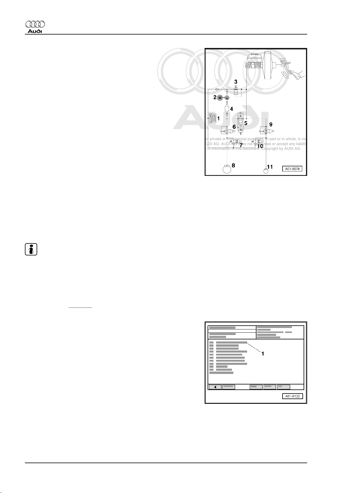
Components of the ABS/EDL system
The hydraulic circuit is a schematic diagram of the ABS/EDL sys‐
tem. The diagram shows only one brake circuit.
1 - Low pressure accumulator
2 - ABS hydraulic pump -V64-
3 - EDL inlet valve (hydraulic)
4 - Noise damping chamber
5 - EDL change-over/separating valve (electrical) with integra‐
ted pressure limiting valve
6 - Front inlet valve
7 - Front outlet valve
8 - Front wheel
9 - Rear inlet valve
10 - Rear outlet valve
11 - Rear wheel
Test condition
• The wheels are locked individually during final control diagno‐
sis. For this test the mechanical and hydraulic components of
the brake system must be working properly. This means that
the master cylinder is able to build up pressure in all four wheel
brake cylinders and there are no leaks in the hydraulic pipes,
hoses and connections.
Note
If one of the wheels does not lock, perform a visual inspection of
the brake fluid reservoir, the master cylinder, the hydraulic unit
and the wheel cylinders.
Procedure
– Connect vehicle diagnostic, testing and information system -
VAS 5051 A- ⇒ page 7 and select vehicle system “03 - Brake
electronics”. When doing this the ignition must be switched on.
Indicated on -VAS 5051 A- :
– Release handbrake.
– Raise vehicle on lifting platform.
– From list -1- select function “03 - Final control diagnosis”.
26 Rep. Gr.01 - Self-diagnosis, electrical checks
Page 31

Protected by copyright. Copying for private or commercial purposes, in part or in whole, is not
permitted unless authorised by AUDI AG. AUDI AG does not guarantee or accept any liability
with respect to the correctness of information in this document. Copyright by AUDI AG.
Running gear, self-diagnosis - Edition 07.2004
Indicated on -VAS 5051 A- :
A - Final control test waiting, move on to next control element
1 - ABS hydraulic pump V64
– Touch → key.
Indicated on -VAS 5051 A- :
A - Final control diagnosis running, moving on permitted
1 - ABS hydraulic pump V64
• The ABS hydraulic pump -V64- - item 2- should start up audi‐
bly.
Note
♦
When you put your foot on the brake pedal you can feel it vi‐
brating. This is because the hydraulic pump -V64- is producing
pressure pulses in the brake pipes. The pressure pulses in‐
duce the vibrations that can be felt at the brake pedal.
♦
The pressure pulses in the brake pipes are not sufficient to
lock the wheels.
Audi TT 1999 ➤
– Touch → key.
Indicated on -VAS 5051 A- :
A - Final control diagnosis running, moving on permitted
2 - Operate brakes
– Depress brake pedal and and touch → within 10 seconds.
Indicated on -VAS 5051 A- :
A - Final control diagnosis running, moving on permitted
3 - IFL: 0V OFL: 0V Wheel FL locked
3. ABS/EDL and ABS/EDL/TCS, ITT Mark 20 without ESP 27
Page 32

Protected by copyright. Copying for private or commercial purposes, in part or in whole, is not
permitted unless authorised by AUDI AG. AUDI AG does not guarantee or accept any liability
with respect to the correctness of information in this document. Copyright by AUDI AG.
Audi TT 1999 ➤
Running gear, self-diagnosis - Edition 07.2004
• Brake pedal must not give.
• When you press the brake pedal, brake fluid pressure will be
built up in all four wheel brake cylinders.
• The hydraulic EDL valve -3- closes, the front wheels -8- and
rear wheels -11- are locked.
Note
This test step in the final control diagnosis corresponds to
the“pressure build-up” phase during ABS-controlled braking.
– Touch → key.
Indicated on -VAS 5051 A- :
A - Final control diagnosis running, moving on permitted
4 - IFL: VBAT OFL: 0V Wheel FL locked
– Keep pressing the brake pedal.
• The hydraulic EDL valve -3- remains closed.
• The front inlet valve -6- is activated, which interrupts the supply
to the wheel brake cylinder; however, the fluid pressure is still
maintained in the wheel cylinder.
• The front left wheel -8- remains locked.
Note
This test step in the final control diagnosis corresponds to
the“maintain pressure” phase during ABS-controlled braking.
– Touch → key.
28 Rep. Gr.01 - Self-diagnosis, electrical checks
Page 33

Protected by copyright. Copying for private or commercial purposes, in part or in whole, is not
permitted unless authorised by AUDI AG. AUDI AG does not guarantee or accept any liability
with respect to the correctness of information in this document. Copyright by AUDI AG.
Running gear, self-diagnosis - Edition 07.2004
Indicated on -VAS 5051 A- :
A - Final control diagnosis running, moving on permitted
5 - IFL: VBAT OFL: VBAT Wheel FL free to turn
– Keep pressing the brake pedal.
• The inlet valve -6- and the outlet valve -7- for the front left
wheel -8- are activated.
• The ABS hydraulic pump -V64- -item 2- starts running and re‐
duces the brake fluid pressure in the wheel brake cylinder via
the open outlet valve.
• The brake pedal must not give, and should press back harder
against your foot.
• The front left wheel -8- is free to turn.
Audi TT 1999 ➤
Note
♦
This test step in the final control diagnosis corresponds to
the“pressure reduction” phase during ABS-controlled braking.
♦
If you cannot turn the front left wheel, check whether the brake
line for the front left wheel is correctly connected.
♦
If this is the case, this indicates that there is a mechanical fault
in one of the valves, providing that there is no electrical fault
in the system. Renew the hydraulic control unit ⇒ Brake sys‐
tem; Rep. Gr. 45 .
♦
If the brake pedal gives under your foot, this means that the
inlet valve or the non-return valve connected in parallel with
the inlet valve is leaking. Renew the hydraulic control unit ⇒
Brake system; Rep. Gr. 45 .
– Touch → key within the next 10 seconds.
Indicated on -VAS 5051 A- :
A - Final control diagnosis running, moving on permitted
6 - IFL: VBAT OFL: 0V Wheel FL free
3. ABS/EDL and ABS/EDL/TCS, ITT Mark 20 without ESP 29
Page 34

Protected by copyright. Copying for private or commercial purposes, in part or in whole, is not
permitted unless authorised by AUDI AG. AUDI AG does not guarantee or accept any liability
with respect to the correctness of information in this document. Copyright by AUDI AG.
Audi TT 1999 ➤
Running gear, self-diagnosis - Edition 07.2004
– Keep pressing the brake pedal.
• The hydraulic EDL valve -3- remains closed.
• The ABS hydraulic pump -V64- - item 2- should stop running.
• Only the inlet valve -6- is now activated, and this interrupts the
supply to the wheel brake cylinder.
• The front left wheel -8- is free to turn.
Note
If the wheel is not free to turn, this means that the inlet valve or
the non-return valve connected in parallel with the inlet valve is
leaking. Renew the hydraulic control unit ⇒ Brake system; Rep.
Gr. 45 .
– Touch → key.
Indicated on -VAS 5051 A- :
A - Final control diagnosis running, moving on permitted
7 - IFL: 0V OFL: 0V Wheel FL locked
– Keep pressing the brake pedal.
• The inlet valve -6- is no longer activated and does not interrupt
the supply to the wheel brake cylinder.
• Brake pedal will give perceptibly under your foot.
• Brake fluid pressure is built up again in the front left wheel
cylinder -8- - the wheel is locked.
– Touch → key.
30 Rep. Gr.01 - Self-diagnosis, electrical checks
Page 35

Protected by copyright. Copying for private or commercial purposes, in part or in whole, is not
permitted unless authorised by AUDI AG. AUDI AG does not guarantee or accept any liability
with respect to the correctness of information in this document. Copyright by AUDI AG.
Running gear, self-diagnosis - Edition 07.2004
Indicated on -VAS 5051 A- :
A - Final control diagnosis running, moving on permitted
8 - Release brakes
– Release brake pedal.
– Touch → key.
Indicated on -VAS 5051 A- :
A - Final control diagnosis running, moving on permitted
9 - Operate brakes
Note
♦
Continue the final control diagnosis to check the front right,
rear left and rear right wheels in turn.
♦
The test steps are the same as for the front left wheel, so they
are not described in detail.
Audi TT 1999 ➤
After testing on rear right wheel is completed:
– Touch → key.
Indicated on -VAS 5051 A- :
A - Final control diagnosis running, moving on permitted
30 - EDL valves/Hyd-P: VBAT FL/FR wheel locked
3. ABS/EDL and ABS/EDL/TCS, ITT Mark 20 without ESP 31
Page 36

Protected by copyright. Copying for private or commercial purposes, in part or in whole, is not
permitted unless authorised by AUDI AG. AUDI AG does not guarantee or accept any liability
with respect to the correctness of information in this document. Copyright by AUDI AG.
Audi TT 1999 ➤
Running gear, self-diagnosis - Edition 07.2004
• The EDL change-over valve -5- and the EDL inlet valve -3- are
activated.
• The ABS hydraulic pump -V64- - item 2- should start running
for one second. The pump draws brake fluid out of fluid res‐
ervoir via EDL inlet valve.
• The hydraulic pump builds up brake fluid pressure in the EDL
controlled wheel brake cylinders. The front left and front right
wheels -8- are locked.
Note
If the front wheels are not locked, this indicates that there is a
mechanical fault in one of the valves, providing that there is no
electrical fault in the system. Renew the hydraulic control unit ⇒
Brake system; Rep. Gr. 45 .
– Touch → key.
Indicated on -VAS 5051 A- :
A - Final control diagnosis competed
– Terminate function “03 - Final control diagnosis” by pressing
the ← key.
• Final control diagnosis is completed. The ABS warning lamp
-K47- and the red “brake warning” symbol should go out.
Note
♦
There is a fault in the system if the ABS warning lamp -K47does not go out.
♦
Adhere exactly to the test sequence: First interrogate fault
memory, then erase.
3.7 Basic setting
The function “04 - Basic setting” can be used to perform the fol‐
lowing procedures:
♦ Bleeding brake system via display group 001 ⇒ page 32 if
brake fluid reservoir has been completely emptied. Basic set‐
ting is only necessary if one or more of the chambers in the
brake fluid reservoir has been completely emptied (e.g. leaks
in brake system).
♦ Only four-wheel drive vehicles: switching off longitudinal ac‐
celeration sender -G251- via display group 040 ⇒ page 35
(e.g. to check the brake system on test rollers).
♦ Only four-wheel drive vehicles: performing zero compensation
of longitudinal acceleration sender -G251- in display group
069 ⇒ page 36 (e.g. after renewing the following compo‐
nents: ABS with EDL control unit -J104- or longitudinal accel‐
eration sender -G251- ).
3.7.1 Bleeding brake system if brake fluid res‐
ervoir has run dry
Basic setting is only necessary if one or more of the chambers in
the brake fluid reservoir has been completely emptied (e.g. leaks
in brake system).
32 Rep. Gr.01 - Self-diagnosis, electrical checks
Page 37

Protected by copyright. Copying for private or commercial purposes, in part or in whole, is not
permitted unless authorised by AUDI AG. AUDI AG does not guarantee or accept any liability
with respect to the correctness of information in this document. Copyright by AUDI AG.
Running gear, self-diagnosis - Edition 07.2004
Special tools and workshop equipment required
♦ Brake charge and bleed equipment -VAS 5234- or upgrade kit
and extraction unit -V.A.G 1869 A-
Caution
♦ When using brake charge and bleed equipment -VAS
5234- to replenish the brake fluid, make sure that filling
pressure does not exceed 1 bar.
♦ If the filling pressure exceeds 1 bar, a hydraulically con‐
trolled change-over valve for the EDL function prevents
unrestricted flushing of the EDL-related parts of the hy‐
draulic unit. Proper bleeding is then no longer ensured.
♦ For this reason the brake fluid pressure must be reduced
to 1 bar on the brake charge and bleed equipment ⇒ Op‐
erating Manual -VAS 5234- or -V.A.G 1869 A-
♦ The charge and bleeder unit -V.A.G 1238/B- is not suitable
for bleeding the brake system by using the function “04 Basic setting”.
Audi TT 1999 ➤
Note
If only charge and bleeder unit -V.A.G 1238/B- is available, switch
the unit on and off as necessary to ensure that sufficient brake
fluid is always present in the reservoir.
Procedure
– Connect vehicle diagnostic, testing and information system -
VAS 5051 A- ⇒ page 7 and select vehicle system “03 - Brake
electronics”. When doing this the ignition must be switched on.
– Connect the brake charge and bleed equipment -VAS 5234-
or -V.A.G 1869 A- .
– Open bleed screws in prescribed sequence and pre-bleed
brake calipers.
1 - Simultaneously bleed both front left and front right brake cali‐
per
2 - Simultaneously bleed both rear left and rear right brake caliper
– With bleeder bottle hoses attached, leave bleed screws open
until the brake fluid emerges free from bubbles.
3. ABS/EDL and ABS/EDL/TCS, ITT Mark 20 without ESP 33
Page 38

Protected by copyright. Copying for private or commercial purposes, in part or in whole, is not
permitted unless authorised by AUDI AG. AUDI AG does not guarantee or accept any liability
with respect to the correctness of information in this document. Copyright by AUDI AG.
Audi TT 1999 ➤
Running gear, self-diagnosis - Edition 07.2004
Bleeding
Indicated on -VAS 5051 A- :
– From list -1-, select function “04 - Basic setting”.
Indicated on -VAS 5051 A- :
1 - Enter display group
– Use keypad -2- to enter “001” for “Display group number 001”
and confirm by pressing the Q key.
• The ABS warning lamp -K47- flashes.
Indicated on -VAS 5051 A- :
1 - Basic setting
2 - Display group 1
3 - Press and hold pedal ...
– Press pedal with substantial foot pressure and hold.
• Pedal moves down, hydraulic pump starts up briefly, pedal
comes back
Indicated on -VAS 5051 A- :
1 - Release pedal; FR/FL bleeder screws OPEN <>
– Release pedal, open front bleed screws.
– Press ↑ key to switch to display group 002.
Indicated on -VAS 5051 A- :
1 - Basic setting
2 - Display group 2
3 - Please wait ... (10 secs.)
– Wait 10 seconds.
• Hydraulic pump starts up briefly
Indicated on -VAS 5051 A- :
1 - Press pedal 10X; bleed screws CLOSED <>
– Press pedal 10 times, close front bleed screws.
– Press ↑ key to switch to display group 003.
34 Rep. Gr.01 - Self-diagnosis, electrical checks
Page 39

Protected by copyright. Copying for private or commercial purposes, in part or in whole, is not
permitted unless authorised by AUDI AG. AUDI AG does not guarantee or accept any liability
with respect to the correctness of information in this document. Copyright by AUDI AG.
Running gear, self-diagnosis - Edition 07.2004
Indicated on -VAS 5051 A- :
1 - Basic setting
2 - Display group 3
3 - Press and hold pedal ...
– Repeat bleeding procedure as described above.
– Press the ↑ key in each case to switch to next highest display
group until display group 017 is reached.
Indicated on -VAS 5051 A- :
1 - Basic setting
2 - Display group 17
3 - Part bleeding ended ...
– Terminate function “04 - Basic setting” by pressing the ← key.
– The brake system must now be bled ⇒ Brake system; Rep.
Gr. 47 .
Audi TT 1999 ➤
3.7.2 Switching off longitudinal acceleration
sender -G251- (only vehicles with fourwheel drive)
♦ The longitudinal acceleration sender -G251- must be switched
off in display group 040 when checking the brake system of a
four-wheel drive vehicle on test rollers.
♦ After completion of the check, the longitudinal acceleration
sender -G251- must be reactivated by switching the ignition
off and back on again.
Procedure
– Connect vehicle diagnostic, testing and information system -
VAS 5051 A- ⇒ page 7 and select vehicle system “03 - Brake
electronics”. When doing this the ignition must be switched on.
Indicated on -VAS 5051 A- :
– From list -1-, select function “04 - Basic setting”.
3. ABS/EDL and ABS/EDL/TCS, ITT Mark 20 without ESP 35
Page 40

Protected by copyright. Copying for private or commercial purposes, in part or in whole, is not
permitted unless authorised by AUDI AG. AUDI AG does not guarantee or accept any liability
with respect to the correctness of information in this document. Copyright by AUDI AG.
Audi TT 1999 ➤
Running gear, self-diagnosis - Edition 07.2004
Indicated on -VAS 5051 A- :
1 - Enter display group
– Use keypad -2- to enter “040” for “display group number 040”
and confirm by pressing the Q key.
Indicated on -VAS 5051 A- :
A - Basic setting
B - Display group 40
• The ABS warning lamp -K47- flashes.
The longitudinal acceleration sender -G251- is now deactivated.
– Terminate function “04 - Basic setting” by pressing the ← key.
– Select function “06 - End output” from list.
– After completion of the check, the longitudinal acceleration
sender -G251- must be reactivated by switching the ignition
off and back on again.
3.7.3 Performing zero compensation of longi‐
tudinal acceleration sender -G251- (only
vehicles with four-wheel drive)
Zero compensation must be performed if the ABS with EDL con‐
trol unit -J104- or the longitudinal acceleration sender -G251were renewed, or if required by the fault table.
• Vehicle is standing horizontal on a flat base.
– Connect vehicle diagnostic, testing and information system -
VAS 5051 A- ⇒ page 7 and select vehicle system “03 - Brake
electronics”. When doing this the ignition must be switched on.
Indicated on -VAS 5051 A- :
– From list -1- select diagnostic function “11 - Login procedure”
or “11 - Coding II”.
36 Rep. Gr.01 - Self-diagnosis, electrical checks
Page 41

Protected by copyright. Copying for private or commercial purposes, in part or in whole, is not
permitted unless authorised by AUDI AG. AUDI AG does not guarantee or accept any liability
with respect to the correctness of information in this document. Copyright by AUDI AG.
Running gear, self-diagnosis - Edition 07.2004
Indicated on -VAS 5051 A- :
1 - Enter code word
– Use keypad -2- to enter code “40168” and confirm entry by
touching Q key.
Note
If display on -VAS 5051 A- reads “function unknown or function
can not be performed at present” the login procedure or coding II
were not successful. Repeat login procedure or coding II.
– Terminate function “11 - Login procedure” or “11 - Coding II”
by touching ← key.
Indicated on -VAS 5051 A- :
– From list -1-, select function “04 - Basic setting”.
Audi TT 1999 ➤
Indicated on -VAS 5051 A- :
1 - Enter display group
– Use keypad -2- to enter “069” for “display group number 069”
and confirm by pressing the Q key.
• The ABS warning lamp -K47- flashes.
Indicated on -VAS 5051 A- :
A - Basic setting
B - Display group 69
1 - Zero compensation OK
4 - 0.3 m/s
2
Zero compensation of longitudinal acceleration sender -G251- is
now completed.
Note
The display does not return to 0.00 m/s2 after performing zero
compensation successfully.
– Terminate function “04 - Basic setting” by pressing the ← key.
3. ABS/EDL and ABS/EDL/TCS, ITT Mark 20 without ESP 37
Page 42

Protected by copyright. Copying for private or commercial purposes, in part or in whole, is not
permitted unless authorised by AUDI AG. AUDI AG does not guarantee or accept any liability
with respect to the correctness of information in this document. Copyright by AUDI AG.
Audi TT 1999 ➤
Running gear, self-diagnosis - Edition 07.2004
Possible fault messages:
Indicated on -VAS 5051 A- :
1 - Zero compensation is not possible
4 - 5.0 m/s
2
The determined value is outside the tolerance range for zero
compensation.
– Proceed as follows to rectify the fault:
1. Check zero position of longitudinal acceleration sender -
G251- in measured value block 006 ⇒ page 46 .
2. Interrogate fault memory ⇒ page 17 .
3. Erase fault memory ⇒ page 38 .
4. Conclude the transfer of data with the function “06 - End
output”.
5. Switch off ignition.
6. Switch ignition on again.
7. Perform zero compensation again.
3.8 Erasing fault memory
Note
If fault memory cannot be erased, interrogate fault memory again
and rectify fault.
Requirements
• Fault memory interrogated ⇒ page 38 .
• All faults rectified.
After fault memory has been interrogated:
Indicated on -VAS 5051 A- :
– From list -1- select function “05 - Erase fault memory”.
38 Rep. Gr.01 - Self-diagnosis, electrical checks
Page 43

Protected by copyright. Copying for private or commercial purposes, in part or in whole, is not
permitted unless authorised by AUDI AG. AUDI AG does not guarantee or accept any liability
with respect to the correctness of information in this document. Copyright by AUDI AG.
Running gear, self-diagnosis - Edition 07.2004
Indicated on -VAS 5051 A- :
1 - No display (prior to erasing) or
- Fault memory erased
Note
If the message “Fault memory not yet interrogated” appears in
display zone -1-, this means that the test sequence has not been
precisely observed. Fault memory cannot be erased until it has
been interrogated.
2 - Note: Do you want to execute the function? Note: Data will be
erased!
– Touch OK key in display -2-.
– Terminate function “05 - Erasing fault memory” by touching
← key.
3.9 End output
Audi TT 1999 ➤
Indicated on -VAS 5051 A- :
– From list -1- select function “06 - End output”.
Indicated on -VAS 5051 A- :
– When this display appears switch off ignition and unplug di‐
agnostic connector.
– Switch on ignition.
• The ABS warning lamp -K47- should go out after approx. 2
seconds.
3.10 Renewing and coding control unit
A new ABS with EDL control unit -J104- supplied as a replace‐
ment part is not encoded. The control unit must be encoded
according to the type of drive train after fitting.
– Removing and installing control unit and hydraulic unit ⇒
Brake system; Rep. Gr. 45 .
3. ABS/EDL and ABS/EDL/TCS, ITT Mark 20 without ESP 39
Page 44

Protected by copyright. Copying for private or commercial purposes, in part or in whole, is not
permitted unless authorised by AUDI AG. AUDI AG does not guarantee or accept any liability
with respect to the correctness of information in this document. Copyright by AUDI AG.
Audi TT 1999 ➤
Running gear, self-diagnosis - Edition 07.2004
Note
If the ABS with EDL control unit -J104- is not coded (Code 00000),
the ABS warning lamp -K47- -item 2- will flash once per second.
The red “brake warning” symbol will start flashing when road
speed first exceeds 10 km/h or engine speed first exceeds 2000
rpm after the ignition is switched on.
– Connect vehicle diagnostic, testing and information system -
VAS 5051 A- ⇒ page 7 and select vehicle system “03 - Brake
electronics”. When doing this the ignition must be switched on.
Indicated on -VAS 5051 A- :
– From list -1- select diagnostic function “07 - Code control unit”.
Indicated on -VAS 5051 A- :
1 - Enter code word
Front-wheel drive vehicles Code number 13204
Four-wheel drive vehicles Code number 13504
Coding table
– Use keypad -2- to enter 5-digit code number according to cod‐
ing table and confirm entry by touching Q key.
Indicated on -VAS 5051 A- :
1 - Coding in progress
– Wait until next readout appears.
1 - Vehicle system coding completed
2 - Control unit identification with new code number (previous
code number in brackets)
40 Rep. Gr.01 - Self-diagnosis, electrical checks
Page 45

Protected by copyright. Copying for private or commercial purposes, in part or in whole, is not
permitted unless authorised by AUDI AG. AUDI AG does not guarantee or accept any liability
with respect to the correctness of information in this document. Copyright by AUDI AG.
Running gear, self-diagnosis - Edition 07.2004
Note
If the control unit is incorrectly coded, the ABS warning lamp -K47-
-item 2- will light up continuously. The “brake warning” symbol
-1- will light up when road speed first exceeds 10 km/h or engine
speed first exceeds 2000 rpm after the ignition is switched on.
– Terminate function “07 - Code control unit” by touching ← key.
Front-wheel drive vehicles:
The work sequence “Renewing and coding control unit” is com‐
pleted with this last step.
Four-wheel drive vehicles:
Indicated on -VAS 5051 A- :
– From list -1- select diagnostic function “11 - Login procedure”
or “11 - Coding II”.
Audi TT 1999 ➤
Indicated on -VAS 5051 A- :
1 - Enter code word
– Use keypad -2- to enter code “40168” and confirm entry by
touching Q key.
Note
If display on -VAS 5051 A- reads “function unknown or function
can not be performed at present” the login procedure or coding II
were not successful. Repeat login procedure or coding II.
– Terminate function “11 - Login procedure” or “11 - Coding II”
by touching ← key.
Indicated on -VAS 5051 A- :
– From list -1-, select function “04 - Basic setting”.
3. ABS/EDL and ABS/EDL/TCS, ITT Mark 20 without ESP 41
Page 46

Protected by copyright. Copying for private or commercial purposes, in part or in whole, is not
permitted unless authorised by AUDI AG. AUDI AG does not guarantee or accept any liability
with respect to the correctness of information in this document. Copyright by AUDI AG.
Audi TT 1999 ➤
Running gear, self-diagnosis - Edition 07.2004
Indicated on -VAS 5051 A- :
1 - Enter display group
– Use keypad -2- to enter “069” for “display group number 069”
and confirm by pressing the Q key.
• The ABS warning lamp -K47- flashes.
Indicated on -VAS 5051 A- :
A - Basic setting
B - Display group 69
1 - Zero compensation OK
4 - 0.3 m/s
2
Note
The display does not return to 0.00 m/s2 after performing zero
compensation successfully.
– Terminate function “04 - Basic setting” by pressing the ← key.
The work sequence “Renewing and coding control unit” is com‐
pleted with this last step.
Note
If a fault is detected during zero compensation ⇒ page 38 .
3.11 Measured value block
The control unit can transfer a considerable amount of test data.
This test data provides information about the operational condi‐
tion of the system and/or sensors connected. In many cases the
transferred test data can be used to assist fault finding and fault
rectification. Since all the information cannot be evaluated simul‐
taneously, the test data is categorised in display groups which
can be selected individually via the display group numbers.
WARNING
♦ To avoid any risk of accident, observe the safety precau‐
tions when using test instruments while road testing the
vehicle ⇒ “1.3 Safety precautions”, page 4 and
⇒ “1.6 Road test”, page 6 .
♦ The ABS/EDL function is deactivated when using vehicle
diagnostic, testing and information system -VAS 5051 Ain the mode “vehicle self-diagnosis” while road testing the
vehicle. However, this is not indicated by illumination of
the warning lamps.
42 Rep. Gr.01 - Self-diagnosis, electrical checks
Page 47

Protected by copyright. Copying for private or commercial purposes, in part or in whole, is not
permitted unless authorised by AUDI AG. AUDI AG does not guarantee or accept any liability
with respect to the correctness of information in this document. Copyright by AUDI AG.
Running gear, self-diagnosis - Edition 07.2004
Note
Self-diagnosis of ABS with EDL control unit -J104- is terminated
if a road speed of 20 km/h is exceeded.
If a fault occurs while function “08 - Reading measured value
block” is being performed, it will be detected. This is indicated by
the ABS warning lamp -K47- lighting up, and helps to trace
“sporadic faults”.
3.11.1 Reading measured value block
– Connect vehicle diagnostic, testing and information system -
VAS 5051 A- ⇒ page 7 and select vehicle system “03 - Brake
electronics”. Ignition must be on or engine must be idling.
Indicated on -VAS 5051 A- :
– From list -1- select diagnostic function “08 - Read measured
value block”.
Audi TT 1999 ➤
Indicated on -VAS 5051 A- :
1 - Enter display group
– Use keypad -2- to select the relevant “Display group number”
⇒ page 44 and confirm by pressing the Q key.
Indicated on -VAS 5051 A- :
1 - Display zones 1 ... 4. If a display zone is vacant the respec‐
tive line remains blank
2 - Indicates the selected display group
3 - Another display group can be selected by pressing one of
the keys.
4 - Another function can be selected by pressing one of the
keys (e.g. selecting function “Basic setting” instead of “Read
measured value block” and vice versa)
3. ABS/EDL and ABS/EDL/TCS, ITT Mark 20 without ESP 43
Page 48

Protected by copyright. Copying for private or commercial purposes, in part or in whole, is not
permitted unless authorised by AUDI AG. AUDI AG does not guarantee or accept any liability
with respect to the correctness of information in this document. Copyright by AUDI AG.
Audi TT 1999 ➤
Running gear, self-diagnosis - Edition 07.2004
List of available display groups
Display group Display zone Signifies Refer to
001 1 Wheel speed, front left ⇒ page 44
2 Wheel speed, front right
3 Wheel speed, rear left
4 Wheel speed, rear right
002 1 Starting speed, front left ⇒ page 44
2 Starting speed, front right
3 Starting speed, rear left
4 Starting speed, rear right
003 1 Brake light switch -F- ⇒ page 45
2 … 4 Vacant
004 1 Communication with engine control unit ⇒ page 45
2 … 4 Vacant
005
006 1
Ignore
Longitudinal acceleration sender -G251-
7)
⇒ page 46
2 … 4 Vacant
7) Four-wheel drive vehicles only.
3.11.2 Test table
Display group 001
This display group is used for checking allocation of speed sen‐
sors to wheels.
– Raise vehicle on lifting platform.
Display zones Explanation
1 ... km/h Wheel speed, front left (turn wheel by hand)
2 ... km/h Wheel speed, front right (turn wheel by hand)
3 ... km/h Wheel speed, rear left (turn wheel by hand)
4 ... km/h Wheel speed, rear right (turn wheel by hand)
Display group 002
This display group is used for the checking wheel speed sensors.
The ABS with EDL control unit -J104- stores the first usable volt‐
age signals from the speed sensor when driving away and dis‐
plays these as set values.
Note
♦
A second mechanic is needed for reading the display when
the vehicle is moving ⇒ “1.3 Safety precautions”, page 4 .
♦
The ABS/EDL function is deactivated when using vehicle di‐
agnosis, testing and information system -VAS 5051 A- in the
function “Read measured value block” while road testing the
vehicle. However, this is not indicated by illumination of the
warning lamps.
♦
Self-diagnosis of ABS with EDL control unit -J104- is termina‐
ted if a road speed of 20 km/h is exceeded.
44 Rep. Gr.01 - Self-diagnosis, electrical checks
Page 49

Protected by copyright. Copying for private or commercial purposes, in part or in whole, is not
permitted unless authorised by AUDI AG. AUDI AG does not guarantee or accept any liability
with respect to the correctness of information in this document. Copyright by AUDI AG.
Display zones Explanation
1
2
... km/h
... km/h
8)
8)
– Drive away slowly until values are displayed on -VAS 5051 A- .
• The displayed values in display zones 1 and 2 must on no account be above
6 km/h when driving away slowly.
If the values are higher than these figures:
– Check wheel speed sensors and rotors on front wheels for damage, proper
installation position and secure seating ⇒ Brake system; Rep. Gr. 45 .
3
4
... km/h
... km/h
8)
8)
– Drive away slowly until values are displayed on -VAS 5051 A- .
• The displayed values in display zones 3 and 4 must not be above 2 km/h when
driving away slowly.
If the values are higher than these figures:
– Check wheel speed sensors and rotors on rear wheels for damage, proper
installation position and secure seating ⇒ Brake system; Rep. Gr. 45 .
8) When the vehicle is stationary the display will read 255 km/h.
Display group 003
Display zones Explanation
1 … Brake light switch -F- :
• 0 = Brake pedal not depressed, Brake light switch “OFF”
• 1 = Brake pedal depressed, Brake light switch “ON”
If readout is not as described:
– Perform electrical check, test step 4 ⇒ page 52
2
3
4
Vacant
Vacant
Vacant
Audi TT 1999 ➤
Running gear, self-diagnosis - Edition 07.2004
Display group 004
Display zones Explanation
1 … Communication with engine control unit:
• 0 = No communication with engine control unit via CAN bus
• 1 = Communication with engine control unit via CAN bus is OK
If display reads “0”:
– Check CAN bus wiring ⇒ page 9
2
3
4
Vacant
Vacant
Vacant
3. ABS/EDL and ABS/EDL/TCS, ITT Mark 20 without ESP 45
Page 50

Protected by copyright. Copying for private or commercial purposes, in part or in whole, is not
permitted unless authorised by AUDI AG. AUDI AG does not guarantee or accept any liability
with respect to the correctness of information in this document. Copyright by AUDI AG.
Audi TT 1999 ➤
Running gear, self-diagnosis - Edition 07.2004
Display group 006
Note
♦
A second mechanic is needed for reading the display when
the vehicle is moving ⇒ “1.3 Safety precautions”, page 4 .
♦
The ABS/ESP function is deactivated when using vehicle di‐
agnosis, testing and information system -VAS 5051 A- in the
function “read measured value block” while road testing the
vehicle. However, this is not indicated by illumination of the
warning lamps.
♦
Self-diagnosis of ABS with EDL control unit -J104- is termina‐
ted if a road speed of 20 km/h is exceeded.
Display zones Explanation
1
m/s
2
Specified values for longitudinal acceleration sensor -G251- .
•
Vehicle stationary: ± 0.5 m/s
• Forward acceleration: value increases continuously
• Reverse acceleration: negative (-) value increases continuously
If readout is not as described:
– Perform electrical check, test step 19 ⇒ page 58
2
3
4
Vacant
Vacant
Vacant
2
3.12 Login procedure or coding II
The login procedure or coding II is required for zero compensation
of several components.
Procedure
– Connect vehicle diagnostic, testing and information system -
VAS 5051 A- ⇒ page 7 and select vehicle system “03 - Brake
electronics”. When doing this the ignition must be switched on.
Indicated on -VAS 5051 A- :
– From list -1- select diagnostic function “11 - Login procedure”
or “11 - Coding II”.
46 Rep. Gr.01 - Self-diagnosis, electrical checks
Page 51

Protected by copyright. Copying for private or commercial purposes, in part or in whole, is not
permitted unless authorised by AUDI AG. AUDI AG does not guarantee or accept any liability
with respect to the correctness of information in this document. Copyright by AUDI AG.
Audi TT 1999 ➤
Running gear, self-diagnosis - Edition 07.2004
Indicated on -VAS 5051 A- :
1 - Enter code word
– Use keypad -2- to enter code “40168” and confirm entry by
touching Q key.
Note
If display on -VAS 5051 A- reads “function unknown or function
can not be performed at present” the login procedure or coding II
were not successful. Repeat login procedure or coding II.
– Terminate function “11 - Login procedure” or “11 - Coding II”
by touching ← key.
– Continue in function “04 - Basic setting” ⇒ page 37 .
3.13 Electrical check of ABS/EDL and ABS/EDL/TCS ITT Mark 20 without ESP
Special tools and workshop
equipment required
♦ Hand-held multimeter -
V.A.G 1526 B- or vehicle
diagnostic, testing and in‐
formation system VAS 5051 A- with test leads
-VAS 5051 A/7-
♦ Adapter set -V.A.G 1594 C-
♦ Test box -V.A.G 1598/21-
3. ABS/EDL and ABS/EDL/TCS, ITT Mark 20 without ESP 47
Page 52

Protected by copyright. Copying for private or commercial purposes, in part or in whole, is not
permitted unless authorised by AUDI AG. AUDI AG does not guarantee or accept any liability
with respect to the correctness of information in this document. Copyright by AUDI AG.
Audi TT 1999 ➤
Running gear, self-diagnosis - Edition 07.2004
The test steps can be used:
♦ For vehicles on which the self diagnosis does not give any
indication of the source of the fault. Work through the complete
electrical check.
♦ For vehicles on which the self diagnosis provides a direct in‐
dication of the source of the fault. Only carry out the test steps
recommended in the fault table (to trace a specific fault).
Requirements
• Voltage supply of vehicle OK.
• Fuses OK ⇒ Current flow diagrams, Electrical fault finding and
Fitting locations.
• Earth connections checked for corrosion and loose contact
⇒ Current flow diagrams, Electrical fault finding and Fitting lo‐
cations.
• All electrical consumers switched off.
3.14 Connecting adapter -V.A.G 1598/21-
(test box) to ABS with EDL control unit J104-
– Switch off ignition.
– Remove cover at front left in engine compartment -arrows-.
– If fitted, disconnect air intake hose for secondary air pump
-1- from air cleaner housing.
– Detach air intake hose -2- at air mass meter.
– Unplug electrical connector at air mass meter -3-.
– Unscrew bolts -4- and -5-.
– Take out air cleaner housing.
48 Rep. Gr.01 - Self-diagnosis, electrical checks
Page 53

Protected by copyright. Copying for private or commercial purposes, in part or in whole, is not
permitted unless authorised by AUDI AG. AUDI AG does not guarantee or accept any liability
with respect to the correctness of information in this document. Copyright by AUDI AG.
Running gear, self-diagnosis - Edition 07.2004
– Release 25-pin connector at ABS with EDL control unit -J104-
-arrow 1- and detach connector -arrow 2-.
– Connect adapter -V.A.G 1598/21- (test box) -item 1- to un‐
plugged 25-pin connector -2- of ABS with EDL control unit J104- .
Caution
To prevent damage to the electronic components, select the
respective measuring range and note the test requirements
prior to connecting test leads.
Audi TT 1999 ➤
– Perform all steps listed for “fault rectification if reading does
not match specification”.
– Only carry out the test steps recommended in the fault table
(to trace a specific fault).
– After performing electrical check, plug 25-pin connector onto
pins of ABS with EDL control unit -J104- and secure connec‐
tor.
Note
♦
Use hand-held multimeter -V.A.G 1526 B- with test leads from
-V.A.G 1594 C- or vehicle diagnostic, testing and information
system -VAS 5051 A- with test leads -VAS 5051 A/7- for the
electrical check.
♦
The socket designations of the adapter -V.A.G 1598/21- (test
box) are identical to the contact designations of the ABS with
EDL control unit -J104- in the current flow diagram.
♦
Incorrect test procedures can cause system damage. Do not
make bridging connections between any contacts other than
those listed in the test table.
♦
The specified values are valid for an ambient temperature be‐
tween 0 ... 40 °C.
♦
If measured values differ from specifications, locate fault ac‐
cording to current flow diagram.
♦
If the measured values only differ slightly from the specifica‐
tions, clean the sockets and plugs of the testers and test leads
(with contact spray -G 000 700 04- ) and repeat the check.
♦
Before renewing components, check wiring and connections.
Repeat resistance check on the component, particularly where
specifications call for a resistance of less than 10Ω.
3. ABS/EDL and ABS/EDL/TCS, ITT Mark 20 without ESP 49
Page 54

Protected by copyright. Copying for private or commercial purposes, in part or in whole, is not
permitted unless authorised by AUDI AG. AUDI AG does not guarantee or accept any liability
with respect to the correctness of information in this document. Copyright by AUDI AG.
Audi TT 1999 ➤
Running gear, self-diagnosis - Edition 07.2004
25-pin connector of ABS with EDL control unit -J104- / sockets on
adapter -V.A.G 1598/21- (test box)
1 - Speed sensor, front left -G47- “+” 15 - ♦ Vehicles with TCS: Traction control system
switch -E132- and traction control system
warning lamp -K86-
2 - Speed sensor, front left -G47- “–”
♦ Vehicles with four-wheel drive: Longitudinal
acceleration sender -G251-
3 - Coding bridge to contact 14 16 - ABS warning lamp -K474 - Power supply, terminal 15 in dash panel wiring
17 -
Longitudinal acceleration sender -G251-
harness (via fuse)
5 - Speed sensor, rear left -G46- “+” 18 - Brake light switch -F6 - Speed sensor, rear left -G46- “–” 19 - Speed sensor, front right -G45- “+”
7 - Diagnosis K-wire 20 - Speed sensor, front right -G45- “–”
8 - Earth point in wiring harness of engine com‐
partment
9 - Battery “+” via fuse 22 - Speed sensor, rear right -G44- “–”
21 - Vacant
10 - CAN bus Low 23 - Speed sensor, rear right -G44- “+”
11 - CAN bus High 24 - Earth terminal 31
12 - Vacant 25 - Battery “+” ( ABS hydraulic pump -V64- via
fuse)
13 -
Longitudinal acceleration sender -G251-
14 - Coding bridge to contact 3
9) Four-wheel drive vehicles only.
9)
3.15 Test table
9)
Overview of test steps
Item tested Test step
Power supply (terminal 30) for ABS hydraulic pump -
– Perform test step 1 ⇒ page 51
V64Power supply (terminal 30) for ABS hydraulic unit -
– Perform test step 2 ⇒ page 51
N55Power supply (terminal 15) for ABS with EDL control
– Perform test step 3 ⇒ page 51
unit -J104Brake light switch -F- – Perform test step 4 ⇒ page 52
Resistance of speed sensor, front right -G45- – Perform test step 5 ⇒ page 52
Resistance of speed sensor, front left -G47- – Perform test step 6 ⇒ page 52
Resistance of speed sensor, rear right -G44- – Perform test step 7 ⇒ page 53
Resistance of speed sensor, rear left -G46- – Perform test step 8 ⇒ page 53
Voltage signal of speed sensor, front right -G45- – Perform test step 9 ⇒ page 54
Voltage signal of speed sensor, front left -G47- – Perform test step 10 ⇒ page 54
50 Rep. Gr.01 - Self-diagnosis, electrical checks
Page 55

Protected by copyright. Copying for private or commercial purposes, in part or in whole, is not
permitted unless authorised by AUDI AG. AUDI AG does not guarantee or accept any liability
with respect to the correctness of information in this document. Copyright by AUDI AG.
Audi TT 1999 ➤
Running gear, self-diagnosis - Edition 07.2004
Item tested Test step
Voltage signal of speed sensor, rear right -G44- – Perform test step 11 ⇒ page 54
Voltage signal of speed sensor, rear left -G46- – Perform test step 12 ⇒ page 55
Coding bridge – Perform test step 13 ⇒ page 55
ABS warning lamp -K47- – Perform test step 14 ⇒ page 55
“Brake warning” symbol in display of driver information
– Perform test step 15 ⇒ page 56
system.
ABS hydraulic pump -V64- – Perform test step 16 ⇒ page 56
Traction control system warning lamp -K86- – Perform test step 17 ⇒ page 57
Traction control system switch -E132- – Perform test step 18 ⇒ page 57
Wiring for longitudinal acceleration sender -G251- – Perform test step 19 ⇒ page 58
Test step No. 1
-V.A.G
Item tested Test conditions and addi‐
1598/21-
Sockets
24 + 25 Power supply
(terminal 30) for
ABS hydraulic
pump -V64-
Test step No. 2
-V.A.G
Item tested Test conditions and addi‐
1598/21-
Sockets
8 + 9 Power supply
(terminal 30) for
ABS hydraulic
unit -N55-
tional operations
• Ignition off
– Select measuring
range: voltage meas‐
urement
tional operations
• Ignition off
– Select measuring
range: voltage meas‐
urement
Specifica‐
tion
Approx.
battery volt‐
age
Specifica‐
tion
Approx.
battery volt‐
age
Fault rectification if reading does
not match specification
– Check wiring according to cur‐
rent flow diagram:
♦ Between contact 24 and earth
♦ Between contact 25 and termi‐
nal 30
Fault rectification if reading does
not match specification
– Check wiring according to cur‐
rent flow diagram:
♦ Between contact 8 and earth
♦ Between contact 9 and terminal
30
Test step No. 3
-V.A.G
Item tested Test conditions and addi‐
1598/21-
Sockets
8 + 4 Power supply
(terminal 15) for
ABS with EDL
control unit J104-
tional operations
• Ignition on
Specifica‐
tion
Fault rectification if reading does
not match specification
3. ABS/EDL and ABS/EDL/TCS, ITT Mark 20 without ESP 51
Page 56

Protected by copyright. Copying for private or commercial purposes, in part or in whole, is not
permitted unless authorised by AUDI AG. AUDI AG does not guarantee or accept any liability
with respect to the correctness of information in this document. Copyright by AUDI AG.
Audi TT 1999 ➤
Running gear, self-diagnosis - Edition 07.2004
-V.A.G
Item tested Test conditions and addi‐
1598/21-
Sockets
Test step No. 4
-V.A.G
Item tested Test conditions and addi‐
1598/21-
Sockets
8 + 18 Brake light switch
-F-
Specifica‐
tional operations
– Select measuring
range: voltage meas‐
urement
tion
Approx.
battery volt‐
age
Specifica‐
tional operations
• Ignition off
tion
– Select measuring
range: voltage meas‐
urement
– Brake pedal not oper‐
0 V – Check wiring according to cur‐
ated
– Brake pedal operated Approx.
battery volt‐
age
Fault rectification if reading does
not match specification
– Check wiring according to cur‐
rent flow diagram:
♦ Between contact 8 and earth
♦ Between contact 4 and terminal
15
Fault rectification if reading does
not match specification
rent flow diagram:
♦ Between contact 8 and earth
♦ Between contact 18 and termi‐
nal 30
Test step No. 5
-V.A.G
Item tested Test conditions and addi‐
1598/21-
Sockets
19 + 20 Resistance of
speed sensor,
front right -G45-
Test step No. 6
-V.A.G
Item tested Test conditions and addi‐
1598/21-
Sockets
1 + 2 Resistance of
speed sensor,
front left -G47-
tional operations
• Ignition off
– Select measuring
range: resistance
Specifica‐
tion
1.0...1.3 kΩ – Check connector of speed sen‐
Fault rectification if reading does
not match specification
sor
measurement
– Move wiring to speed sensor
when checking (loose contact)
Specifica‐
tional operations
• Ignition off
tion
– Renew speed sensor if wiring is
OK.
Fault rectification if reading does
not match specification
52 Rep. Gr.01 - Self-diagnosis, electrical checks
Page 57

Protected by copyright. Copying for private or commercial purposes, in part or in whole, is not
permitted unless authorised by AUDI AG. AUDI AG does not guarantee or accept any liability
with respect to the correctness of information in this document. Copyright by AUDI AG.
Audi TT 1999 ➤
Running gear, self-diagnosis - Edition 07.2004
-V.A.G
Item tested Test conditions and addi‐
1598/21-
Sockets
Test step No. 7
-V.A.G
Item tested Test conditions and addi‐
1598/21-
Sockets
22 + 23 Resistance of
speed sensor,
rear right -G44-
tional operations
– Select measuring
range: resistance
measurement
tional operations
• Ignition off
– Select measuring
range: resistance
measurement
Specifica‐
tion
Fault rectification if reading does
not match specification
1.0...1.3 kΩ – Check connector of speed sen‐
sor
– Move wiring to speed sensor
when checking (loose contact)
– Renew speed sensor if wiring is
OK.
Specifica‐
tion
Fault rectification if reading does
not match specification
1.0...1.3 kΩ – Check connector of speed sen‐
sor
– Move wiring to speed sensor
when checking (loose contact)
Test step No. 8
-V.A.G
Item tested Test conditions and addi‐
1598/21-
Sockets
5 + 6 Resistance of
speed sensor,
rear left -G46-
– Renew speed sensor if wiring is
OK.
tional operations
• Ignition off
– Select measuring
range: resistance
Specifica‐
tion
1.0...1.3 kΩ – Check connector of speed sen‐
Fault rectification if reading does
not match specification
sor
measurement
– Move wiring to speed sensor
when checking (loose contact)
– Renew speed sensor if wiring is
OK.
3. ABS/EDL and ABS/EDL/TCS, ITT Mark 20 without ESP 53
Page 58

Protected by copyright. Copying for private or commercial purposes, in part or in whole, is not
permitted unless authorised by AUDI AG. AUDI AG does not guarantee or accept any liability
with respect to the correctness of information in this document. Copyright by AUDI AG.
Audi TT 1999 ➤
Running gear, self-diagnosis - Edition 07.2004
Test step No. 9
-V.A.G
Item tested Test conditions and addi‐
1598/21-
Sockets
19 + 20 Voltage signal of
speed sensor,
front right -G45-
Test step No. 10
-V.A.G
Item tested Test conditions and addi‐
1598/21-
Sockets
1 + 2 Voltage signal of
speed sensor,
front left -G47-
tional operations
• Vehicle raised
• Ignition off
– Select measuring
range: voltage meas‐
urement (alternating
voltage)
– Rotate front right
wheel at approx. 1
revolution per second.
tional operations
• Vehicle raised
• Ignition off
– Select measuring
range: voltage meas‐
urement (alternating
voltage)
– Rotate front left wheel
at approx. 1 revolution
per second
Specifica‐
tion
Min. 65 mV
alternating
voltage
Specifica‐
tion
Min. 65 mV
alternating
voltage
Fault rectification if reading does
not match specification
– Check speed sensor for inter‐
changed wiring (read measured
value block 001 ⇒ page 44 )
– Check installation of speed sen‐
sor and rotor ⇒ Brake system;
Rep. Gr. 45
Fault rectification if reading does
not match specification
– Check speed sensor for inter‐
changed wiring (read measured
value block 001 ⇒ page 44 )
Test step No. 11
-V.A.G
Item tested Test conditions and addi‐
1598/21-
Sockets
22 + 23 Voltage signal of
speed sensor,
rear right -G44-
– Check installation of speed sen‐
sor and rotor ⇒ Brake system;
Rep. Gr. 45
tional operations
• Vehicle raised
Specifica‐
tion
Fault rectification if reading does
not match specification
• Ignition off
– Select measuring
range: voltage meas‐
urement (alternating
voltage)
– Rotate rear right
wheel at approx. 1
revolution per second
190...
1140 mV al‐
ternating
– Check speed sensor for inter‐
changed wiring (read measured
value block 001 ⇒ page 44 )
voltage
– Check installation of speed sen‐
sor and rotor ⇒ Brake system;
Rep. Gr. 45
54 Rep. Gr.01 - Self-diagnosis, electrical checks
Page 59

Protected by copyright. Copying for private or commercial purposes, in part or in whole, is not
permitted unless authorised by AUDI AG. AUDI AG does not guarantee or accept any liability
with respect to the correctness of information in this document. Copyright by AUDI AG.
Test step No. 12
Audi TT 1999 ➤
Running gear, self-diagnosis - Edition 07.2004
-V.A.G
1598/21-
Item tested Test conditions and addi‐
tional operations
Sockets
5 + 6 Voltage signal of
speed sensor,
rear left -G46-
• Vehicle raised
• Ignition off
– Select measuring
range: voltage meas‐
urement (alternating
voltage)
– Rotate rear left wheel
at approx. 1 revolution
per second
Test step No. 13
-V.A.G
1598/21-
Item tested Test conditions and addi‐
tional operations
Sockets
3 + 14 Coding bridge • Ignition off
– Select measuring
range: resistance
measurement
Specifica‐
tion
Fault rectification if reading does
not match specification
190...
1140 mV al‐
ternating
– Check speed sensor for inter‐
changed wiring (read measured
value block 001 ⇒ page 44 )
voltage
– Check installation of speed sen‐
sor and rotor ⇒ Brake system;
Rep. Gr. 45
Specifica‐
tion
Fault rectification if reading does
not match specification
0…1 Ω – Check wiring and contacts in
plug
– Renew coding bridge if test re‐
sult does not match specifica‐
tion
Test step No. 14
-V.A.G
1598/21-
Item tested Test conditions and addi‐
tional operations
Sockets
– ABS warning
lamp -K47-
• Ignition off
• 25-pin connector con‐
nected to ABS with
EDL control unit J104-
– Switch on ignition ABS warn‐
Specifica‐
tion
ing lamp K47- should
light up for 2
seconds
and then go
out
Fault rectification if reading does
not match specification
– Switch off ignition
– Connect test box -
V.A.G 1598/21-
– Check wiring according to cur‐
rent flow diagram:
♦ Perform test step 3
♦ Check wiring between contact
16 of -V.A.G 1598/21- and in‐
strument cluster.
– Interrogate fault memory of in‐
strument cluster (dash panel in‐
sert) ⇒ Electrical system, selfdiagnosis; Rep. Gr. 01
3. ABS/EDL and ABS/EDL/TCS, ITT Mark 20 without ESP 55
Page 60

Protected by copyright. Copying for private or commercial purposes, in part or in whole, is not
permitted unless authorised by AUDI AG. AUDI AG does not guarantee or accept any liability
with respect to the correctness of information in this document. Copyright by AUDI AG.
Audi TT 1999 ➤
Running gear, self-diagnosis - Edition 07.2004
Test step No. 15
-V.A.G
Item tested Test conditions and addi‐
1598/21-
Sockets
– “Brake warning”
symbol in display
of driver informa‐
tion system.
Test step No. 16
tional operations
• Ignition off
• 25-pin connector con‐
nected to ABS with
EDL control unit J104-
• Electrical connector
unplugged from one
of the front speed sen‐
sors.
– Switch on ignition,
start engine and in‐
crease engine speed
to above 2000 rpm.
– Plug in electrical con‐
nector after testing is
completed and inter‐
rogate and erase fault
memory
Specifica‐
tion
“Brake
warning”
symbol
lights up
Fault rectification if reading does
not match specification
– Switch off ignition
– Connect test box -
V.A.G 1598/21-
– Check wiring according to cur‐
rent flow diagram:
♦ Perform test step 3
♦ Check wiring between contact
16 of -V.A.G 1598/21- and in‐
strument cluster.
– Interrogate fault memory of in‐
strument cluster (dash panel in‐
sert) ⇒ Electrical system, selfdiagnosis; Rep. Gr. 01
-V.A.G
Item tested Test conditions and addi‐
1598/21-
Sockets
– ABS hydraulic
pump -V64-
tional operations
• 25-pin connector con‐
nected to ABS with
EDL control unit J104-
• Ignition on
• Vehicle diagnostic,
testing and informa‐
tion system -VAS
5051 A- connected
– Initiate final control di‐
agnosis ⇒ page 25
and activate ABS hy‐
draulic pump -V64-
Specifica‐
tion
Pump mo‐
tor starts up
Fault rectification if reading does
not match specification
– Switch off ignition
– Check wiring according to cur‐
rent flow diagram:
♦ Perform test step 1
♦ Wiring from contact 1 of 2-pin
connector at ABS hydraulic
pump -V64- to control unit
♦ Wiring from contact 2 of 2-pin
connector at ABS hydraulic
pump -V64- to control unit
– If no fault is found in wiring, re‐
move hydraulic control unit and
renew hydraulic pump with
valve block ⇒ Brake system;
Rep. Gr. 45
56 Rep. Gr.01 - Self-diagnosis, electrical checks
Page 61

Protected by copyright. Copying for private or commercial purposes, in part or in whole, is not
permitted unless authorised by AUDI AG. AUDI AG does not guarantee or accept any liability
with respect to the correctness of information in this document. Copyright by AUDI AG.
Test step No. 17
Audi TT 1999 ➤
Running gear, self-diagnosis - Edition 07.2004
-V.A.G
Item tested Test conditions and addi‐
1598/21-
Sockets
– Traction control
system warning
lamp -K86-
Specifica‐
tional operations
• No faults stored in
tion
fault memory
• Ignition off
• 25-pin connector con‐
nected to ABS with
EDL control unit J104-
– Switch on ignition Traction
control sys‐
tem warn‐
ing lamp K86- should
light up for 2
seconds
and then go
out
Fault rectification if reading does
not match specification
– Switch off ignition
– Connect test box -
V.A.G 1598/21-
– Check wiring according to cur‐
rent flow diagram:
♦ Perform test step 3
♦ Check wiring between contact
15 of -V.A.G 1598/21- and in‐
strument cluster.
– Interrogate fault memory of in‐
strument cluster (dash panel in‐
sert) ⇒ Electrical system, selfdiagnosis; Rep. Gr. 01
Test step No. 18
-V.A.G
Item tested Test conditions and addi‐
1598/21-
Sockets
– Traction control
system switch E132-
tional operations
• Ignition off
Specifica‐
tion
Fault rectification if reading does
not match specification
• 25-pin connector con‐
nected to ABS with
EDL control unit J104-
• Test step 17 per‐
formed
– Switch on ignition
Traction
control sys‐
– Operate traction con‐
trol system switch E132-
tem warn‐
ing lamp -
K86- lights
up
– Operate traction con‐
trol system switch E132- again
Traction
control sys‐
tem warn‐
ing lamp -
– Switch off ignition
– Connect test box -
V.A.G 1598/21-
K86- goes
out
3. ABS/EDL and ABS/EDL/TCS, ITT Mark 20 without ESP 57
Page 62

Protected by copyright. Copying for private or commercial purposes, in part or in whole, is not
permitted unless authorised by AUDI AG. AUDI AG does not guarantee or accept any liability
with respect to the correctness of information in this document. Copyright by AUDI AG.
Audi TT 1999 ➤
Running gear, self-diagnosis - Edition 07.2004
-V.A.G
Item tested Test conditions and addi‐
1598/21-
Sockets
8 + 15
Test step No. 19
-V.A.G
Item tested Test conditions and addi‐
1598/21-
Sockets
10)
13 + 1
Wiring for longitu‐
dinal acceleration
sender -G251-
tional operations
– Select measuring
range: voltage meas‐
urement
– Switch on ignition
– Do not operate Trac‐
tion control system
switch -E132-
– Operate traction con‐
trol system switch E132-
tional operations
• Ignition off
• Electrical connector at
longitudinal accelera‐
tion sender -G251unplugged
Specifica‐
tion
Fault rectification if reading does
not match specification
Approx. 0 V – Check fuses and wiring accord‐
ing to current flow diagram:
♦ Between contact 15 of -V.A.G
1598/21- and contact 5 of switch
♦ Between contact 6 of switch and
terminal 15
♦ Between contact 2 of switch and
earth
Approx.
– Renew switch if wiring is OK.
battery volt‐
age
Specifica‐
tion
Fault rectification if reading does
not match specification
– Select measuring
range: resistance
17 + 2
15 + 3
10)
10)
measurement
– Check wiring for short
to positive or earth.
10) Contact at connector of longitudinal acceleration sender -G251- .
max. 1.5Ω – Service wiring according to cur‐
rent flow diagram
max. 1.5Ω
max. 1.5Ω
∞ Ω
58 Rep. Gr.01 - Self-diagnosis, electrical checks
Page 63

Protected by copyright. Copying for private or commercial purposes, in part or in whole, is not
permitted unless authorised by AUDI AG. AUDI AG does not guarantee or accept any liability
with respect to the correctness of information in this document. Copyright by AUDI AG.
Running gear, self-diagnosis - Edition 07.2004
4 ABS/EDL/TCS/ESP ITT Mark 20
♦ The Audi TT with ESP is equipped with the ABS/EDL/ESP ITT
Mark 20 system or the ABS/EDL/TCS/ESP ITT Mark 20 sys‐
tem.
♦ The data signals are transmitted via CAN bus.
4.1 Retrofit installation of ESP
♦ ESP may have been retrofitted by AUDI AG on vehicles not
originally equipped with this system. These vehicles are iden‐
tified by the PR number “1AZ” on the data sticker.
♦ Another identifying feature is the adapter connector -1- on the
air cleaner housing.
♦ This connector must not be unplugged by the workshop. Self-
diagnosis and electrical check are as for the ESP fitted as
standard.
4.2 Electrical/electronic components and fitting locations
Audi TT 1999 ➤
1 - Rotor for speed sensor (rear
right)
❑ Checking speed sensor
rotor ⇒ Brake system;
Rep. Gr. 45
❑ Speed sensor rotor is
welded to wheel hub; re‐
moving and installing
wheel hub ⇒ Running
gear, front-wheel drive
and four-wheel drive;
Rep. Gr. 42
2 - Rear right speed sensor G44-
❑ Removing and instal‐
ling, fitting speed sensor
wiring ⇒ Brake system;
Rep. Gr. 45
3 - Rear left speed sensor G46-
❑ Removing and instal‐
ling, fitting speed sensor
wiring ⇒ Brake system;
Rep. Gr. 45
4 - Rotor for speed sensor (rear
left)
❑ Checking speed sensor
rotor ⇒ Brake system;
Rep. Gr. 45
❑ Speed sensor rotor is
welded to wheel hub; re‐
moving and installing
wheel hub ⇒ Running
gear, front-wheel drive
and four-wheel drive;
Rep. Gr. 42
4. ABS/EDL/TCS/ESP ITT Mark 20 59
Page 64

Protected by copyright. Copying for private or commercial purposes, in part or in whole, is not
permitted unless authorised by AUDI AG. AUDI AG does not guarantee or accept any liability
with respect to the correctness of information in this document. Copyright by AUDI AG.
Audi TT 1999 ➤
Running gear, self-diagnosis - Edition 07.2004
5 - Handbrake warning lamp -K14-
❑ Fitting location: in instrument cluster
❑ Function ⇒ page 14
6 - ABS warning lamp -K47-
❑ Fitting location: in instrument cluster
❑ Function ⇒ page 14
7 - “Brake warning” symbol
❑ Appears in the display of the driver information system
❑ Function ⇒ page 14
8 - Stabilisation program warning lamp -K155-
❑ Fitting location: in instrument cluster
❑ Function ⇒ page 14
9 - Brake light suppression relay (ESP) -J508-
❑ Fitting location: in 13-position relay carrier behind driver's storage compartment
10 - Brake light switch -F-
❑ Can be checked via reading measured value block ⇒ page 113
❑ Removing and installing ⇒ Brake system; Rep. Gr. 45
11 - Rotor for speed sensor, front left
❑ Checking speed sensor rotor ⇒ Brake system; Rep. Gr. 45
❑ Speed sensor rotor is welded to wheel hub; removing and installing wheel hub ⇒ Running gear, front-
wheel drive and four-wheel drive; Rep. Gr. 40
12 - Front left speed sensor -G47-
❑ Removing and installing, fitting speed sensor wiring ⇒ Brake system; Rep. Gr. 45
13 - Hydraulic control unit
❑ The hydraulic control unit comprises the ABS hydraulic pump -V64- , the ABS hydraulic unit -N55- and
the ABS with EDL control unit -J104- .
❑ Fitting location on left-hand drive vehicles ⇒ page 61
❑ Fitting location on right-hand drive vehicles ⇒ page 62
❑ Tested by self-diagnosis
❑ Only unplug 47-pin connector when the ignition is switched off
❑ Assignment of 47-pin connector ⇒ page 120
❑ Removing and installing ⇒ Brake system; Rep. Gr. 45
❑ Perform coding of ABS with EDL control unit -J104- after renewal ⇒ page 103
14 - Rotor for speed sensor, front right
❑ Checking speed sensor rotor ⇒ Brake system; Rep. Gr. 45
❑ Speed sensor rotor is welded to wheel hub; removing and installing wheel hub ⇒ Running gear, front-
wheel drive and four-wheel drive; Rep. Gr. 40
15 - Front right speed sensor -G45-
❑ Removing and installing, fitting speed sensor wiring ⇒ Brake system; Rep. Gr. 45
16 - Longitudinal acceleration sender -G251-
❑ Only four-wheel drive vehicles
❑ Fitting location: at A-pillar on passenger's side
❑ Can be checked via reading measured value block ⇒ page 115
❑ Refer to ⇒ Brake system; Rep. Gr. 45 for removing and installing, then perform zero compensation in
basic setting ⇒ page 97
17 - Brake pressure sender 2 -G214-
❑ Can be checked via reading measured value block ⇒ page 114
❑ Refer to ⇒ Brake system; Rep. Gr. 45 for removing and installing, then perform zero compensation in
basic setting ⇒ page 95
60 Rep. Gr.01 - Self-diagnosis, electrical checks
Page 65

Protected by copyright. Copying for private or commercial purposes, in part or in whole, is not
permitted unless authorised by AUDI AG. AUDI AG does not guarantee or accept any liability
with respect to the correctness of information in this document. Copyright by AUDI AG.
Audi TT 1999 ➤
Running gear, self-diagnosis - Edition 07.2004
18 - Brake pressure sender 1 -G201-
❑ Can be checked via reading measured value block ⇒ page 114
❑ Refer to ⇒ Brake system; Rep. Gr. 45 for removing and installing, then perform zero compensation in
basic setting ⇒ page 95
19 - Brake pressure solenoid trip switch -F84-
❑ Can be checked in basic setting ⇒ page 87 and in measured value block ⇒ page 113
❑ Brake servo must be renewed completely if brake pressure solenoid trip switch is defective
20 - Brake pressure solenoid -N247-
❑ Can be checked in basic setting ⇒ page 87
❑ Brake servo must be renewed completely if brake pressure solenoid is defective
21 - Brake fluid level warning contact -F34-
22 - Lateral acceleration sender -G200-
❑ Fitting location: next to steering column
❑ Can be checked via reading measured value block ⇒ page 114
❑ Refer to ⇒ Brake system; Rep. Gr. 45 for removing and installing, then perform zero compensation in
basic setting ⇒ page 93
23 - Yaw rate sender -G202-
❑ Fitting location: next to steering column
❑ Can be checked via reading measured value block ⇒ page 114
❑ Removing and installing ⇒ Brake system; Rep. Gr. 45
24 - Button for TCS and ESP -E256-
❑ Fitting location: on the centre console
25 - Steering angle sender -G85-
❑ Fitting location: on steering column between steering wheel and steering column switch
❑ Can be checked via reading measured value block ⇒ page 114
❑ Refer to ⇒ Brake system; Rep. Gr. 45 for removing and installing, then perform zero compensation in
basic setting ⇒ page 91
26 - Handbrake warning switch -F9-
❑ Fitting location: on handbrake lever
Hydraulic control unit on vehicles with left-hand drive
1 - Brake servo (10”)
2 - Hydraulic unit
3 - ABS with EDL control unit -J104- , 47-pin (bolted to hydraulic
unit)
4. ABS/EDL/TCS/ESP ITT Mark 20 61
Page 66

Protected by copyright. Copying for private or commercial purposes, in part or in whole, is not
permitted unless authorised by AUDI AG. AUDI AG does not guarantee or accept any liability
with respect to the correctness of information in this document. Copyright by AUDI AG.
Audi TT 1999 ➤
Running gear, self-diagnosis - Edition 07.2004
Hydraulic control unit on vehicles with right-hand drive
1 - Brake servo (7”/8”)
2 - Hydraulic unit
3 - ABS with EDL control unit -J104- , 47-pin (bolted to hydraulic
unit)
4.3 Faults displayed by warning lamps in in‐
strument cluster
1 - “Brake warning” symbol
2 - ABS warning lamp -K47-
3 - Handbrake warning lamp -K14-
4 - Stabilisation program warning lamp -K155-
“Brake warning”
symbol
ABS warning
lamp -K47-
Stabilisation
program warn‐
ing lamp -K155-
11)
Explanation
On On On Test sequence after switching on ignition (first two sec‐
onds).
Off Off Off System OK (2 seconds after switching on ignition)
Off Off On TCS/ESP failure or TCS/ESP deactivated by switch;
ABS, EDL and EBPD are active
Off Off flashes TCS/ESP control function is operating
Off On On ABS/EDL/TCS system failure (e.g. wheel speed sen‐
sor defective), the EBPD remains fully functional.
On On On ABS/EDL/TCS/EBPD system failure (e.g. several
wheel speed sensors defective)
On Off Off Brake fluid level too low; all systems remain functional
11) Used to be designated as traction control system warning lamp -K86- in cur‐
rent flow diagrams of an earlier date.
WARNING
There is a risk of accident if the ABS warning lamp -K47- and
the “brake warning symbol” both light up.The function of the
brake system will be impaired. As the brake pressure is no
longer controlled by the electronic brake force distribution the
rear wheels tend to brake excessively.Due to this the rear of
the vehicle may break away unexpectedly.
62 Rep. Gr.01 - Self-diagnosis, electrical checks
Page 67

Protected by copyright. Copying for private or commercial purposes, in part or in whole, is not
permitted unless authorised by AUDI AG. AUDI AG does not guarantee or accept any liability
with respect to the correctness of information in this document. Copyright by AUDI AG.
Running gear, self-diagnosis - Edition 07.2004
The ABS warning lamp -K47- -item 2- lights up during the test
sequence (self-test)
The system runs through an automatic test sequence when the
ignition is switched on: the ABS warning lamp -K47- is activated
by the ABS with EDL control unit -J104- and lights up for 2 sec‐
onds. During this period the control unit tests the following func‐
tions via self-test.
♦ The voltage supply is checked, at least 10.0 V.
♦ The control unit including the valve windings is checked.
♦ A speed sensor check (electrical test) is carried out; this is only
completed at 20 km/h.
♦ Control unit code is checked.
If the system does not perform the test sequence:
– Check voltage supply of ABS with EDL control unit -J104-
(perform electrical check, step 3 ⇒ page 123 ).
The ABS warning lamp -K47- -item 2- stays on after the test se‐
quence is completed
If a fault affecting only the anti-lock brake system is detected by
self-diagnosis, the ABS is switched off. The conventional brake
system remains fully functional.
The causes of the fault may be as follows:
♦ Voltage supply is below 10 Volts.
♦ A fault exists which affects only the ABS.
♦ A sensor fault has occurred after the last start (sporadic fault).
In this case the ABS warning lamp goes out automatically after
the vehicle is started again and the road speed exceeds 20 km/
h.
♦ Connection between ABS with EDL control unit -J104- and in‐
strument cluster is faulty or instrument cluster faulty (perform
electrical check, step 14 ⇒ page 127 ).
Audi TT 1999 ➤
The ABS warning lamp -K47- -item 2- goes out after the test se‐
quence is completed, but “brake warning symbol” -1- remains on
and the gong sounds three times
All systems remain functional.
The causes of the fault may be as follows:
♦ Brake fluid level too low.
♦ Fault in instrument cluster ⇒ Electrical system, self-diagnosis;
Rep. Gr. 01 or ⇒ Current flow diagrams, Electrical fault finding
and Fitting locations.
4. ABS/EDL/TCS/ESP ITT Mark 20 63
Page 68

Protected by copyright. Copying for private or commercial purposes, in part or in whole, is not
permitted unless authorised by AUDI AG. AUDI AG does not guarantee or accept any liability
with respect to the correctness of information in this document. Copyright by AUDI AG.
Audi TT 1999 ➤
Running gear, self-diagnosis - Edition 07.2004
A - Vehicles without navigation system: the ABS warning lamp K47- -item 2- does not go out after the test sequence is comple‐
ted, and “brake warning” symbol -1- is on
B - Vehicles with navigation system: the ABS warning lamp -K47-
-item 2- does not go out after test sequence is completed and
handbrake warning lamp -K14- -3- lights up when vehicle speed
first exceeds 10 km/h or engine speed first exceeds 2000 rpm,
and the gong sounds three times
The ABS system is defective and the EBPD system deactivated.
WARNING
There is a risk of accident if the ABS warning lamp -K47- and
the “brake warning symbol” both light up.The function of the
brake system will be impaired. As the brake pressure is no
longer controlled by the electronic brake force distribution the
rear wheels tend to brake excessively.Due to this the rear of
the vehicle may break away unexpectedly.
The stabilising program warning lamp -K155- -item 4- remains on
after the test sequence is completed
The causes of the fault may be as follows:
♦ A fault in the system affecting only the TCS/ESP. ABS/EDL
and EBPD remain fully functional.
♦ The TCS/ESP system was switched off by the TCS and ESP
button -E256- .
♦ Short circuit to positive in TCS and ESP button -E256-
♦ Short circuit to earth for activation of stabilisation program
warning lamp -K155- .
♦ Open circuit in wiring for activation of stabilisation program
warning lamp -K155- .
The stabilisation program warning lamp -K155- -item 4- lights up
for 100 milliseconds after switching ignition on
♦ A coding without TCS/ESP control has been entered.
64 Rep. Gr.01 - Self-diagnosis, electrical checks
Page 69

Protected by copyright. Copying for private or commercial purposes, in part or in whole, is not
permitted unless authorised by AUDI AG. AUDI AG does not guarantee or accept any liability
with respect to the correctness of information in this document. Copyright by AUDI AG.
Running gear, self-diagnosis - Edition 07.2004
The ABS warning lamp -K47- -item 2- and the “brake warning”
symbol -1- flash and the stabilisation program warning lamp K155- remains on after the test sequence is completed
The causes of the fault may be as follows:
♦ The control unit is not coded (Code 00000).
Note
If the ABS warning lamp -K47- and the “brake warning” symbol
do not light up but the brake system is not fully functional, the fault
must be traced in the conventional brake system ⇒ Brake system;
Rep. Gr. 46 and ⇒ Brake system; Rep. Gr. 47 .
4.4 Performing self-diagnosis of ABS/EDL/ TCS/ESP ITT Mark 20 system
List of available functions
– With ignition switched off, connect vehicle diagnostic, testing
and information system -VAS 5051 A- with diagnosis lead VAS 5051 A/1- to diagnosis connector and select vehicle
system “03 - Brake electronics” ⇒ page 7 .
The following functions are available from the list -1-:
Audi TT 1999 ➤
Functions Page
02 Interrogate fault memory ⇒ page 65
03 Final control diagnosis ⇒ page 77
04 Basic setting ⇒ page 84
05 Erase fault memory ⇒ page 102
06 End output ⇒ page 103
07 Code control unit ⇒ page 103
08 Read measured value block ⇒ page 110
11 Login procedure or coding II ⇒ page 116
The other functions displayed are currently not available, or can
be disregarded.
4.5 Interrogating fault memory
– Connect vehicle diagnostic, testing and information system -
VAS 5051 A- ⇒ page 7 and select vehicle system “03 - Brake
electronics”. When doing this the ignition must be switched on.
Indicated on -VAS 5051 A- :
– From list -1- select function “02 - Interrogate fault memory”.
4. ABS/EDL/TCS/ESP ITT Mark 20 65
Page 70

Protected by copyright. Copying for private or commercial purposes, in part or in whole, is not
permitted unless authorised by AUDI AG. AUDI AG does not guarantee or accept any liability
with respect to the correctness of information in this document. Copyright by AUDI AG.
Audi TT 1999 ➤
Running gear, self-diagnosis - Edition 07.2004
Indicated on -VAS 5051 A- :
-1- Content of fault memory No faults detected
or
X faults detected
-2- Fault Fault code
Fault location
Type of fault
A - If a fault was detected:
– Print out information on screen or self-diagnosis log.
– Terminate function “02 - Interrogate fault memory” by touching
← key.
Indicated on -VAS 5051 A- :
– Rectify fault(s) according to fault tables ⇒ page 66 .
– From list -1- select function “02 - Interrogate fault memory” and
erase fault memory ⇒ page 102 .
– From list -1- select function “06 - End output” ⇒ page 103 .
– Perform road test and interrogate fault memory again.
B - If no fault was detected:
– Terminate function “02 - Interrogate fault memory” by touching
← key.
– Select function “06 - End output” from list ⇒ page 103 .
4.6 Fault tables
Note
♦
The following table includes all faults which can be detected
by the ABS with EDL control unit -J104- and displayed by VAS 5051 A- when interrogating the fault memory.
♦
The contents of the fault memory remains stored until the
memory is erased; Erasing fault memory ⇒ page 102 .
♦
Faults are listed according to a 5-digit fault code, which ap‐
pears in the left-hand column of the fault table.
♦
Sporadic (intermittent) faults are identified as such by the word
“sporadic” appearing on the display.
♦
Check wiring and connectors going to the relevant compo‐
nents according to current flow diagram before renewing com‐
ponents indicated as faulty by -VAS 5051 A- .Also check earth
connections according to current flow diagram. This is partic‐
ularly important if faults are indicated as being “sporadic”.
Fault 00283
Display on -
VAS 5051 A-
00283
Front left speed sensor -G47-
♦ Open circuit, loose contact or short to
positive or earth in speed sensor wire or
speed sensor
Possible cause of fault Fault remedy
– Perform electrical check, step 6
⇒ page 123 and step 10 ⇒ page 125
♦ Speed sensor winding defective
66 Rep. Gr.01 - Self-diagnosis, electrical checks
Page 71

Protected by copyright. Copying for private or commercial purposes, in part or in whole, is not
permitted unless authorised by AUDI AG. AUDI AG does not guarantee or accept any liability
with respect to the correctness of information in this document. Copyright by AUDI AG.
Audi TT 1999 ➤
Running gear, self-diagnosis - Edition 07.2004
Display on -
VAS 5051 A-
♦ Speed sensor or rotor damaged – Check speed sensor and rotor ⇒ Brake
♦ ABS with EDL control unit -J104- defec‐
tive
00283
Front left speed sensor -G47Mechanical fault
• This fault is
only detec‐
♦ Excessive air gap between speed sensor
and rotor.
ted above 20
km/h (carry
out test
drive).
♦ Outlet valves in hydraulic unit defective – Check hydraulic unit in final control diag‐
00283
Front left speed sensor -G47Signal outside tolerance
• This fault is
only detec‐
ted above 20
km/h (carry
out test
♦ Open circuit, loose contact or short to
positive or earth in speed sensor wire or
speed sensor
♦ Speed sensor winding defective
drive).
Possible cause of fault Fault remedy
system; Rep. Gr. 45
– Remove hydraulic control unit, renew
control unit ⇒ Brake system; Rep. Gr.
45 , then code control unit ⇒ page 103
– Check installation of speed sensor and
rotor ⇒ Brake system; Rep. Gr. 45
nosis ⇒ page 77
– Perform electrical check, step 6
⇒ page 123 and step 10 ⇒ page 125
♦ Electrical interference from external in‐
terference sources (high frequency radi‐
ation, e.g. non-insulated ignition cable)
♦ Excessive air gap between speed sensor
and rotor.
♦ Speed sensor or rotor damaged – Check speed sensor and rotor ⇒ Brake
Fault 00285
Display on -
VAS 5051 A-
00285
Possible cause of fault Fault remedy
Front right speed sensor -G45-
♦ Open circuit, loose contact or short to
positive or earth in speed sensor wire or
speed sensor
♦ Speed sensor winding defective
♦ Speed sensor or rotor damaged – Check speed sensor and rotor ⇒ Brake
♦ ABS with EDL control unit -J104- defec‐
tive
00285
Front right speed sensor -G45Mechanical fault
– Read measured value block 001
⇒ page 112
– Check installation of speed sensor and
rotor ⇒ Brake system; Rep. Gr. 45
system; Rep. Gr. 45
– Perform electrical check, step 5
⇒ page 123 and step 9 ⇒ page 125
system; Rep. Gr. 45
– Remove hydraulic control unit, renew
control unit ⇒ Brake system; Rep. Gr.
45 , then code control unit ⇒ page 103
4. ABS/EDL/TCS/ESP ITT Mark 20 67
Page 72

Protected by copyright. Copying for private or commercial purposes, in part or in whole, is not
permitted unless authorised by AUDI AG. AUDI AG does not guarantee or accept any liability
with respect to the correctness of information in this document. Copyright by AUDI AG.
Audi TT 1999 ➤
Running gear, self-diagnosis - Edition 07.2004
Display on -
Possible cause of fault Fault remedy
VAS 5051 A-
• This fault is
only detec‐
♦ Excessive air gap between speed sensor
and rotor.
ted above 20
km/h (carry
out test
drive).
♦ Outlet valves in hydraulic unit defective – Check hydraulic unit in final control diag‐
00285
Front right speed sensor -G45Signal outside tolerance
• This fault is
only detec‐
ted above 20
km/h (carry
out test
♦ Open circuit, loose contact or short to
positive or earth in speed sensor wire or
speed sensor
♦ Speed sensor winding defective
drive).
♦ Electrical interference from external in‐
terference sources (high frequency radi‐
ation, e.g. non-insulated ignition cable)
♦ Excessive air gap between speed sensor
and rotor.
– Check installation of speed sensor and
rotor ⇒ Brake system; Rep. Gr. 45
nosis ⇒ page 77
– Perform electrical check, step 5
⇒ page 123 and step 9 ⇒ page 125
– Read measured value block 001
⇒ page 112
– Check installation of speed sensor and
rotor ⇒ Brake system; Rep. Gr. 45
♦ Speed sensor or rotor damaged – Check speed sensor and rotor ⇒ Brake
Fault 00287
Display on -
VAS 5051 A-
00287
Rear right speed sensor -G44-
♦ Open circuit, loose contact or short to
positive or earth in speed sensor wire or
speed sensor
♦ Speed sensor winding defective
♦ Speed sensor or rotor damaged – Check speed sensor and rotor ⇒ Brake
♦ ABS with EDL control unit -J104- defec‐
tive
00287
Rear right speed sensor -G44Mechanical fault
• This fault is
only detec‐
ted above 20
♦ Excessive air gap between speed sensor
and rotor.
km/h (carry
out test
drive).
system; Rep. Gr. 45
Possible cause of fault Fault remedy
– Perform electrical check, step 7
⇒ page 124 and step 11 ⇒ page 125
system; Rep. Gr. 45
– Remove hydraulic control unit, renew
control unit ⇒ Brake system; Rep. Gr.
45 , then code control unit ⇒ page 103
– Check installation of speed sensor and
rotor ⇒ Brake system; Rep. Gr. 45
♦ Outlet valves in hydraulic unit defective – Check hydraulic unit in final control diag‐
00287
Rear right speed sensor -G44Signal outside tolerance
68 Rep. Gr.01 - Self-diagnosis, electrical checks
nosis ⇒ page 77
Page 73

Protected by copyright. Copying for private or commercial purposes, in part or in whole, is not
permitted unless authorised by AUDI AG. AUDI AG does not guarantee or accept any liability
with respect to the correctness of information in this document. Copyright by AUDI AG.
Audi TT 1999 ➤
Running gear, self-diagnosis - Edition 07.2004
Display on -
VAS 5051 A-
• This fault is
only detec‐
ted above 20
km/h (carry
out test
♦ Open circuit, loose contact or short to
positive or earth in speed sensor wire or
speed sensor
♦ Speed sensor winding defective
drive).
♦ Electrical interference from external in‐
terference sources (high frequency radi‐
ation, e.g. non-insulated ignition cable)
♦ Excessive air gap between speed sensor
and rotor.
♦ Speed sensor or rotor damaged – Check speed sensor and rotor ⇒ Brake
Fault 00290
Display on -
VAS 5051 A-
00290
Rear left speed sensor -G46-
♦ Open circuit, loose contact or short to
positive or earth in speed sensor wire or
speed sensor
♦ Speed sensor winding defective
Possible cause of fault Fault remedy
– Perform electrical check, step 7
⇒ page 124 and step 11 ⇒ page 125
– Read measured value block 001
⇒ page 112
– Check installation of speed sensor and
rotor ⇒ Brake system; Rep. Gr. 45
system; Rep. Gr. 45
Possible cause of fault Fault remedy
– Perform electrical check, step 8
⇒ page 124 and step 12 ⇒ page 126
♦ Speed sensor or rotor damaged – Check speed sensor and rotor ⇒ Brake
♦ ABS with EDL control unit -J104- defec‐
tive
00290
Rear left speed sensor -G46Mechanical fault
• This fault is
only detec‐
♦ Excessive air gap between speed sensor
and rotor.
ted above 20
km/h (carry
out test
drive).
♦ Outlet valves in hydraulic unit defective – Check hydraulic unit in final control diag‐
♦ Excessive air gap between speed sensor
and rotor.
00290
Rear left speed sensor -G46Signal outside tolerance
• This fault is
only detec‐
ted above 20
km/h (carry
out test
♦ Open circuit, loose contact or short to
positive or earth in speed sensor wire or
speed sensor
♦ Speed sensor winding defective
drive).
system; Rep. Gr. 45
– Remove hydraulic control unit, renew
control unit ⇒ Brake system; Rep. Gr.
45 , then code control unit ⇒ page 103
– Check installation of speed sensor and
rotor ⇒ Brake system; Rep. Gr. 45
nosis ⇒ page 77
– Check installation of speed sensor and
rotor ⇒ Brake system; Rep. Gr. 45
– Perform electrical check, step 8
⇒ page 124 and step 12 ⇒ page 126
4. ABS/EDL/TCS/ESP ITT Mark 20 69
Page 74

Protected by copyright. Copying for private or commercial purposes, in part or in whole, is not
permitted unless authorised by AUDI AG. AUDI AG does not guarantee or accept any liability
with respect to the correctness of information in this document. Copyright by AUDI AG.
Audi TT 1999 ➤
Running gear, self-diagnosis - Edition 07.2004
Display on -
VAS 5051 A-
Fault 00538
Display on -
VAS 5051 A-
00538
Reference voltage
Possible cause of fault Fault remedy
♦ Electrical interference from external in‐
terference sources (high frequency radi‐
– Read measured value block 001
⇒ page 112
ation, e.g. non-insulated ignition cable)
♦ Excessive air gap between speed sensor
and rotor.
– Check installation of speed sensor and
rotor ⇒ Brake system; Rep. Gr. 45
♦ Speed sensor or rotor damaged – Check speed sensor and rotor ⇒ Brake
system; Rep. Gr. 45
Possible cause of fault Fault remedy
♦ Open circuit, loose contact or short circuit
to positive or earth in voltage supply wir‐
ing for lateral acceleration sender G200- , brake pressure sender 1 -G201- ,
– Perform electrical check, test step 19
⇒ page 130 , test step 20 ⇒ page 130 ,
test step 21 ⇒ page 131 , test step 22
⇒ page 131
yaw rate sender -G202- or brake pres‐
sure sender 2 -G214-
Fault 00668
Display on -
VAS 5051 A-
00668
Vehicle voltage, terminal 30
Signal outside tolerance
♦ Fuse defective
♦ Open circuit, loose circuit or short circuit
to positive or earth in voltage supply wir‐
ing
Fault 00778
Display on -
VAS 5051 A-
00778
Steering angle sender -G85No communication
♦ Faults in CAN bus wiring – Check CAN bus wiring between ABS with
♦ High and Low CAN bus wiring inter‐
changed
♦ The output of one of the control units
communicating via the CAN bus is de‐
fective.
Possible cause of fault Fault remedy
– Perform electrical check, step 1
⇒ page 122 and step 2 ⇒ page 122
Possible cause of fault Fault remedy
EDL control unit -J104- and steering an‐
gle sender -G85- ⇒ page 9
– Check CAN Bus wiring for interchanged
connections according to current flow di‐
agram
– Check CAN bus wiring ⇒ page 9
70 Rep. Gr.01 - Self-diagnosis, electrical checks
Page 75

Protected by copyright. Copying for private or commercial purposes, in part or in whole, is not
permitted unless authorised by AUDI AG. AUDI AG does not guarantee or accept any liability
with respect to the correctness of information in this document. Copyright by AUDI AG.
Audi TT 1999 ➤
Running gear, self-diagnosis - Edition 07.2004
Display on -
VAS 5051 A-
♦ Steering angle sender -G85- defective – Read measured value block 004
00778
Steering angle sender -G85No setting or wrong setting
♦ Steering angle sender -G85- sends no
values or incorrect values
00778
Steering angle sender -G85Mechanical fault
♦ Installation position of steering angle
sender -G85- not OK
♦ Running gear geometry not OK – Perform wheel alignment ⇒ Running
♦ No zero compensation performed after
removing and installing steering wheel
Possible cause of fault Fault remedy
⇒ page 114
– Renew sender ⇒ Brake system; Rep. Gr.
45 , then perform zero compensation in
basic setting ⇒ page 91
– Perform zero compensation
⇒ page 91
– Check installation position of sender ⇒
Brake system; Rep. Gr. 45
gear, front-wheel drive and four-wheel
drive; Rep. Gr. 44
– Perform zero compensation
⇒ page 91
00778
Steering angle sender -G85Implausible signal
♦ Installation position of steering angle
sender -G85- not OK
♦ Running gear geometry not OK – Perform wheel alignment ⇒ Running
♦ Vibrations in steering due to wear – Renew defective components, then per‐
00778
Steering angle sender -G85defective
♦ Steering angle sender -G85- sends no
values or incorrect values
Fault 00810
Display on -
Possible cause of fault Fault remedy
VAS 5051 A-
00810
Sender 1/2 for brake pressure
Implausible signal
♦ Open circuit in earth connection to brake
pressure sender 1 -G201- or brake pres‐
sure sender 2 -G214-
♦ Short circuit in signal wiring to brake pres‐
sure sender 1 -G201- or brake pressure
sender 2 -G214-
– Check installation position of sender ⇒
Brake system; Rep. Gr. 45
gear, front-wheel drive and four-wheel
drive; Rep. Gr. 44
form zero compensation in basic setting
⇒ page 91
– Renew sender ⇒ Brake system; Rep. Gr.
45 , then perform zero compensation in
basic setting ⇒ page 91
– Perform electrical check, step 21
⇒ page 131 and step 22 ⇒ page 131
4. ABS/EDL/TCS/ESP ITT Mark 20 71
Page 76

Protected by copyright. Copying for private or commercial purposes, in part or in whole, is not
permitted unless authorised by AUDI AG. AUDI AG does not guarantee or accept any liability
with respect to the correctness of information in this document. Copyright by AUDI AG.
Audi TT 1999 ➤
Running gear, self-diagnosis - Edition 07.2004
Display on -
Possible cause of fault Fault remedy
VAS 5051 A-
♦ Brake pressure sender 1 -G201- or brake
pressure sender 2 -G214- defective
♦ One hydraulic brake circuit has failed – Check brake system ⇒ Brake system;
Fault 00812
Display on -
Possible cause of fault Fault remedy
VAS 5051 A-
00812
Brake pressure solenoid trip switch -F84-
♦ Open circuit, loose circuit or short circuit
to positive or earth in wiring connection
going to brake pressure solenoid trip
switch -F84-
♦ Brake pressure solenoid trip switch -F84-
defective
♦ Brake servo defective – Renew brake servo ⇒ Brake system;
– Renew sender ⇒ Brake system; Rep. Gr.
45 , then perform zero compensation in
basic setting ⇒ page 99
Rep. Gr. 47
– Perform electrical check, test step 23
⇒ page 131
– Perform function test in basic setting
⇒ page 87
Rep. Gr. 47 , then perform function test
in basic setting ⇒ page 87
Fault 00813
Display on -
Possible cause of fault Fault remedy
VAS 5051 A-
00813
Brake pressure sender 2 -G214Electrical fault in circuit
♦ Open circuit, loose circuit or short circuit
to positive or earth in wiring connection
going to brake pressure sender 2 -G214-
♦ Brake pressure sender 2 -G214- defec‐
tive
Fault 00814
Display on -
Possible cause of fault Fault remedy
VAS 5051 A-
00814
Brake pressure solenoid -N247-
♦ Open circuit, loose circuit or short circuit
to positive or earth in wiring connection
going to brake pressure solenoid -N247-
– Perform electrical check, test step 22
⇒ page 131
– Renew sender ⇒ Brake system; Rep. Gr.
45 , then perform zero compensation in
basic setting ⇒ page 95
– Perform electrical check, test step 24
⇒ page 132
♦ Brake pressure solenoid -N247- defec‐
tive
♦ Brake servo defective – Renew brake servo ⇒ Brake system;
72 Rep. Gr.01 - Self-diagnosis, electrical checks
– Perform function test in basic setting
⇒ page 87
Rep. Gr. 47 , then perform function test
in basic setting ⇒ page 87
Page 77

Protected by copyright. Copying for private or commercial purposes, in part or in whole, is not
permitted unless authorised by AUDI AG. AUDI AG does not guarantee or accept any liability
with respect to the correctness of information in this document. Copyright by AUDI AG.
Audi TT 1999 ➤
Running gear, self-diagnosis - Edition 07.2004
Display on -
VAS 5051 A-
♦ Output stage in ABS with EDL control unit
-J104- defective
Fault 01044
Display on -
VAS 5051 A-
01044
Control unit incorrectly coded
♦ An incorrect code number has been en‐
tered
♦ Only vehicles with front-wheel drive: con‐
tact 2 not connected
♦ Only vehicles with four-wheel drive: con‐
tact 2 connected to earth
♦ Coding bridges in wiring harness dam‐
aged
Possible cause of fault Fault remedy
– Remove hydraulic control unit, renew
control unit ⇒ Brake system; Rep. Gr.
45 , then code control unit ⇒ page 103
Possible cause of fault Fault remedy
– Check code ⇒ page 103
– Connect contact 2 to earth
– Remove earth connection at contact 2
– Check wires in wiring harness; perform
electrical check, test step 13
⇒ page 126
Fault 01130
Display on -
VAS 5051 A-
01130
ABS operation
Signal outside tolerance
• This fault is
only detec‐
ted above 20
km/h (carry
out test
drive).
♦ Electrical interference from external in‐
terference sources (high frequency radi‐
ation, e.g. non-insulated ignition cable)
♦ Open circuit, loose contact or short to
positive or earth in wiring
Fault 01276
Display on -
VAS 5051 A-
01276
ABS hydraulic pump -V64Signal outside tolerance
Possible cause of fault Fault remedy
– Check all electrical wiring and connectors
– Erase fault memory
– Perform test drive at more than 20 km/h
– Interrogate fault memory again
If the fault is not rectified:
– Remove hydraulic control unit, renew
control unit ⇒ Brake system; Rep. Gr.
45 , then code control unit ⇒ page 103
Possible cause of fault Fault remedy
4. ABS/EDL/TCS/ESP ITT Mark 20 73
Page 78

Protected by copyright. Copying for private or commercial purposes, in part or in whole, is not
permitted unless authorised by AUDI AG. AUDI AG does not guarantee or accept any liability
with respect to the correctness of information in this document. Copyright by AUDI AG.
Audi TT 1999 ➤
Running gear, self-diagnosis - Edition 07.2004
Display on -
Possible cause of fault Fault remedy
VAS 5051 A-
• This fault is
only detec‐
ted above 20
km/h (carry
♦ Open circuit or short circuit to earth or
positive in internal wiring: ABS with EDL
control unit -J104- / ABS hydraulic pump
-V64out test
drive).
♦ ABS with EDL control unit -J104- defec‐
tive
♦ Pump motor defective – Renew hydraulic control unit ⇒ Brake
Fault 01279
Display on -
Possible cause of fault Fault remedy
VAS 5051 A-
01279
Longitudinal acceleration sender -G251Electrical fault in circuit
12)
♦ Open circuit, loose circuit or short circuit
to positive or earth in wiring connection
going to longitudinal acceleration sender
-G251-
– Check ABS hydraulic pump -V64- via fi‐
nal control diagnosis ⇒ page 77
If ABS hydraulic pump -V64- starts running
during final control diagnosis:
– Perform electrical check, test step 1
⇒ page 122
– Check all wiring and connections for
short to positive or earth according to cur‐
rent flow diagram.
– Remove hydraulic control unit, renew
control unit ⇒ Brake system; Rep. Gr.
45 , then code control unit ⇒ page 103
system; Rep. Gr. 45
– Perform electrical check, test step 25
⇒ page 132
♦ Installation position of longitudinal accel‐
eration sender -G251- not OK
♦ Longitudinal acceleration sender -G251-
defective
12) Four-wheel drive vehicles only.
Fault 01312
Display on -
VAS 5051 A-
01312
Drive train data bus
defective
13)
♦ ABS with EDL control unit -J104- incor‐
rectly coded
♦ Engine control unit incorrectly coded – Check coding of engine control unit ⇒
♦ Faults in CAN bus wiring – Check CAN bus wiring between engine
– Check installation position ⇒ Brake sys‐
tem; Rep. Gr. 45
– Read measured value block 006
⇒ page 115
– Renew sender ⇒ Brake system; Rep. Gr.
45 , then perform zero compensation in
basic setting ⇒ page 97
Possible cause of fault Fault remedy
– Check code ⇒ page 103
Motronic injection and ignition system;
Rep. Gr. 01
control unit and ABS with EDL control unit
-J104- ⇒ page 9
13) Is displayed together with fault “00778 - Steering angle sender: -G85 No communication”.
74 Rep. Gr.01 - Self-diagnosis, electrical checks
Page 79

Protected by copyright. Copying for private or commercial purposes, in part or in whole, is not
permitted unless authorised by AUDI AG. AUDI AG does not guarantee or accept any liability
with respect to the correctness of information in this document. Copyright by AUDI AG.
Fault 01314
Audi TT 1999 ➤
Running gear, self-diagnosis - Edition 07.2004
Display on -
Possible cause of fault Fault remedy
VAS 5051 A-
01314
Engine control unit
No communication
• Signals are
transmitted
between
When displayed as static fault:
♦ ABS with EDL control unit -J104- or en‐
gine control unit not CAN compatible
ABS with
EDL control
unit -J104and engine
♦ Fault in engine control unit – Interrogate fault memory of engine con‐
control unit
via CAN data
bus
When displayed as static and sporadic fault:
♦ Faults in CAN bus wiring
♦ High and Low CAN bus wiring inter‐
changed
♦ The output of one of the control units
communicating via the CAN bus is de‐
fective.
Fault 01324
– Refer to control unit identification of ABS
with EDL control unit -J104- ⇒ page 8 and
engine control unit to check that correct
control units are installed.Allocation ⇒
Parts catalogue
trol unit ⇒ Motronic injection and ignition
system; Rep. Gr. 01 , rectify fault if nec‐
essary and erase fault memory
– Check CAN bus wiring between engine
control unit and ABS with EDL control unit
-J104- ⇒ page 9
– Check CAN Bus wiring for interchanged
connections according to current flow di‐
agram
– Check CAN bus wiring ⇒ page 9
Display on -
Possible cause of fault Fault remedy
VAS 5051 A-
01324
Four-wheel drive control unit -J492No communication
14) Four-wheel drive vehicles only.
14)
♦ Faults in CAN bus wiring – Read measured value block 125
Fault 01423
Display on -
Possible cause of fault Fault remedy
VAS 5051 A-
01423
Lateral acceleration sender -G200Electrical fault in circuit
♦ Open circuit, loose circuit or short circuit
to positive or earth in wiring connection
going to lateral acceleration sender -
G200-
♦ Installation position of lateral accelera‐
tion sender -G200- not OK
⇒ page 115
– Check CAN bus wiring ⇒ page 9
– Perform electrical check, test step 19
⇒ page 130
– Check installation position ⇒ Brake sys‐
tem; Rep. Gr. 45
4. ABS/EDL/TCS/ESP ITT Mark 20 75
Page 80

Protected by copyright. Copying for private or commercial purposes, in part or in whole, is not
permitted unless authorised by AUDI AG. AUDI AG does not guarantee or accept any liability
with respect to the correctness of information in this document. Copyright by AUDI AG.
Audi TT 1999 ➤
Running gear, self-diagnosis - Edition 07.2004
Display on -
Possible cause of fault Fault remedy
VAS 5051 A-
♦ Lateral acceleration sender -G200- de‐
fective
01423
Lateral acceleration sender -G200Implausible signal
♦ Installation position of lateral accelera‐
tion sender -G200- not OK
♦ Lateral acceleration sender -G200- de‐
fective
Fault 01435
Display on -
Possible cause of fault Fault remedy
VAS 5051 A-
01435
Brake pressure sender 1 -G201Electrical fault in circuit
♦ Open circuit, loose circuit or short circuit
to positive or earth in wiring connection
going to brake pressure sender 1 -G201-
– Read measured value block 004
⇒ page 114
– Renew sender ⇒ Brake system; Rep. Gr.
45 , then perform zero compensation in
basic setting ⇒ page 93
– Check installation position ⇒ Brake sys‐
tem; Rep. Gr. 45
– Read measured value block 004
⇒ page 114
– Renew sender ⇒ Brake system; Rep. Gr.
45 , then perform zero compensation in
basic setting ⇒ page 93
– Perform electrical check, test step 21
⇒ page 131
♦ Brake pressure sender 1 -G201- defec‐
tive
Fault 01542
Display on -
VAS 5051 A-
01542
Yaw rate sender -G202Electrical fault in circuit
♦ Open circuit in earth connection to yaw
rate sender -G202-
♦ Installation position of yaw rate sender -
G202- not OK
♦ Yaw rate sender -G202- defective – Read measured value block 004
– Read measured value block, display
group 005 ⇒ page 114
– Renew sender ⇒ Brake system; Rep. Gr.
45 , then perform zero compensation in
basic setting ⇒ page 95
Possible cause of fault Fault remedy
– Perform electrical check, test step 20
⇒ page 130
– Check installation position ⇒ Brake sys‐
tem; Rep. Gr. 45
⇒ page 114
– Renew sender ⇒ Brake system; Rep. Gr.
45 .
76 Rep. Gr.01 - Self-diagnosis, electrical checks
Page 81

Protected by copyright. Copying for private or commercial purposes, in part or in whole, is not
permitted unless authorised by AUDI AG. AUDI AG does not guarantee or accept any liability
with respect to the correctness of information in this document. Copyright by AUDI AG.
Fault 65535
Audi TT 1999 ➤
Running gear, self-diagnosis - Edition 07.2004
Display on -
Possible cause of fault Fault remedy
VAS 5051 A-
65535
Control unit defective
♦ Control unit defective – Remove hydraulic control unit, renew
4.7 Final control diagnosis
The final control diagnosis can be used to check the ABS hy‐
draulic pump -V64- and the correct functioning of the hydraulic
circuits (allocation of brake pipes to wheel brakes and function of
valves). This function will also detect interchanged connections
and leaks.
Note
♦
The vehicle must be raised until all wheels are free to turn.
♦
To avoid overloading the control elements they are only acti‐
vated for a period of 60 or 90 seconds. The final control test
will be terminated if the → key is not pressed within this period.
control unit ⇒ Brake system; Rep. Gr.
45 , then code control unit ⇒ page 103
Do not erase fault memory of old control unit.
The data in the fault memory will help to
identify the malfunction
♦
The ABS warning lamp -K47- and the red “brake warning”
symbol flash during the final control diagnosis.
♦
After depressing the brake pedal several times the vacuum in
the brake servo will be exhausted. Therefore more pressure
must be applied to the brake pedal in order to attain the same
fluid pressure in the brake system as that attained with vac‐
uum.
♦
When vacuum in brake servo is exhausted it can happen that
the wheels do not lock: start engine and build up vacuum in
brake servo.
Meaning of abbreviations indicated on display
IFL = Inlet valve
OFL = Outlet valve
VBAT = Battery voltage; voltage at valve
0V = 0 Volt; No voltage at valve
Hydr-P = ABS hydraulic pump -V64-
4. ABS/EDL/TCS/ESP ITT Mark 20 77
Page 82

Protected by copyright. Copying for private or commercial purposes, in part or in whole, is not
permitted unless authorised by AUDI AG. AUDI AG does not guarantee or accept any liability
with respect to the correctness of information in this document. Copyright by AUDI AG.
Audi TT 1999 ➤
Running gear, self-diagnosis - Edition 07.2004
Components of the ABS/EDL system
The hydraulic circuit is a schematic diagram of the ABS/EDL sys‐
tem. The diagram shows only one brake circuit.
1 - Low pressure accumulator
2 - ABS hydraulic pump -V64-
3 - EDL inlet valve (hydraulic)
4 - Noise damping chamber
5 - EDL change-over/separating valve (electrical) with integra‐
ted pressure limiting valve
6 - Front inlet valve
7 - Front outlet valve
8 - Front wheel
9 - Rear inlet valve
10 - Rear outlet valve
11 - Rear wheel
Test condition
• The wheels are locked individually during final control diagno‐
sis. For this test the mechanical and hydraulic components of
the brake system must be working properly. This means that
the master cylinder is able to build up pressure in all four wheel
brake cylinders and there are no leaks in the hydraulic pipes,
hoses and connections.
Note
If one of the wheels does not lock, perform a visual inspection of
the brake fluid reservoir, the master cylinder, the hydraulic unit
and the wheel cylinders.
Procedure
– Connect vehicle diagnostic, testing and information system -
VAS 5051 A- ⇒ page 7 and select vehicle system “03 - Brake
electronics”. When doing this the ignition must be switched on.
Indicated on -VAS 5051 A- :
– Release handbrake.
– Raise vehicle on lifting platform.
– From list -1- select function “03 - Final control diagnosis”.
78 Rep. Gr.01 - Self-diagnosis, electrical checks
Page 83

Protected by copyright. Copying for private or commercial purposes, in part or in whole, is not
permitted unless authorised by AUDI AG. AUDI AG does not guarantee or accept any liability
with respect to the correctness of information in this document. Copyright by AUDI AG.
Running gear, self-diagnosis - Edition 07.2004
Indicated on -VAS 5051 A- :
A - Final control test waiting, move on to next control element
1 - ABS hydraulic pump V64
– Touch → key.
Indicated on -VAS 5051 A- :
A - Final control diagnosis running, moving on permitted
1 - ABS hydraulic pump V64
• The ABS hydraulic pump -V64- - item 2- should start up audi‐
bly.
Note
♦
When you put your foot on the brake pedal you can feel it vi‐
brating. This is because the hydraulic pump -V64- is producing
pressure pulses in the brake pipes. The pressure pulses in‐
duce the vibrations that can be felt at the brake pedal.
♦
The pressure pulses in the brake pipes are not sufficient to
lock the wheels.
Audi TT 1999 ➤
– Touch → key.
Indicated on -VAS 5051 A- :
A - Final control diagnosis running, moving on permitted
2 - Operate brakes
– Depress brake pedal and and touch → within 10 seconds.
Indicated on -VAS 5051 A- :
A - Final control diagnosis running, moving on permitted
3 - IFL: 0V OFL: 0V Wheel FL locked
4. ABS/EDL/TCS/ESP ITT Mark 20 79
Page 84

Protected by copyright. Copying for private or commercial purposes, in part or in whole, is not
permitted unless authorised by AUDI AG. AUDI AG does not guarantee or accept any liability
with respect to the correctness of information in this document. Copyright by AUDI AG.
Audi TT 1999 ➤
Running gear, self-diagnosis - Edition 07.2004
• Brake pedal must not give.
• When you press the brake pedal, brake fluid pressure will be
built up in all four wheel brake cylinders.
• The hydraulic EDL valve -3- closes, the front wheels -8- and
rear wheels -11- are locked.
Note
This test step in the final control diagnosis corresponds to
the“pressure build-up” phase during ABS-controlled braking.
– Touch → key.
Indicated on -VAS 5051 A- :
A - Final control diagnosis running, moving on permitted
4 - IFL: VBAT OFL: 0V Wheel FL locked
– Keep pressing the brake pedal.
• The hydraulic EDL valve -3- remains closed.
• The front inlet valve -6- is activated, which interrupts the supply
to the wheel brake cylinder; however, the fluid pressure is still
maintained in the wheel cylinder.
• The front left wheel -8- remains locked.
Note
This test step in the final control diagnosis corresponds to
the“maintain pressure” phase during ABS-controlled braking.
– Touch → key.
80 Rep. Gr.01 - Self-diagnosis, electrical checks
Page 85

Protected by copyright. Copying for private or commercial purposes, in part or in whole, is not
permitted unless authorised by AUDI AG. AUDI AG does not guarantee or accept any liability
with respect to the correctness of information in this document. Copyright by AUDI AG.
Running gear, self-diagnosis - Edition 07.2004
Indicated on -VAS 5051 A- :
A - Final control diagnosis running, moving on permitted
5 - IFL: VBAT OFL: VBAT Wheel FL free to turn
– Keep pressing the brake pedal.
• The inlet valve -6- and the outlet valve -7- for the front left
wheel -8- are activated.
• The ABS hydraulic pump -V64- -item 2- starts running and re‐
duces the brake fluid pressure in the wheel brake cylinder via
the open outlet valve.
• The brake pedal must not give, and should press back harder
against your foot.
• The front left wheel -8- is free to turn.
Audi TT 1999 ➤
Note
♦
This test step in the final control diagnosis corresponds to
the“pressure reduction” phase during ABS-controlled braking.
♦
If you cannot turn the front left wheel, check whether the brake
line for the front left wheel is correctly connected.
♦
If this is the case, this indicates that there is a mechanical fault
in one of the valves, providing that there is no electrical fault
in the system. Renew the hydraulic control unit ⇒ Brake sys‐
tem; Rep. Gr. 45 .
♦
If the brake pedal gives under your foot, this means that the
inlet valve or the non-return valve connected in parallel with
the inlet valve is leaking. Renew the hydraulic control unit ⇒
Brake system; Rep. Gr. 45 .
– Touch → key within the next 10 seconds.
Indicated on -VAS 5051 A- :
A - Final control diagnosis running, moving on permitted
6 - IFL: VBAT OFL: 0V Wheel FL free
4. ABS/EDL/TCS/ESP ITT Mark 20 81
Page 86

Protected by copyright. Copying for private or commercial purposes, in part or in whole, is not
permitted unless authorised by AUDI AG. AUDI AG does not guarantee or accept any liability
with respect to the correctness of information in this document. Copyright by AUDI AG.
Audi TT 1999 ➤
Running gear, self-diagnosis - Edition 07.2004
– Keep pressing the brake pedal.
• The hydraulic EDL valve -3- remains closed.
• The ABS hydraulic pump -V64- - item 2- should stop running.
• Only the inlet valve -6- is now activated, and this interrupts the
supply to the wheel brake cylinder.
• The front left wheel -8- is free to turn.
Note
If the wheel is not free to turn, this means that the inlet valve or
the non-return valve connected in parallel with the inlet valve is
leaking. Renew the hydraulic control unit ⇒ Brake system; Rep.
Gr. 45 .
– Touch → key.
Indicated on -VAS 5051 A- :
A - Final control diagnosis running, moving on permitted
7 - IFL: 0V OFL: 0V Wheel FL locked
– Keep pressing the brake pedal.
• The inlet valve -6- is no longer activated and does not interrupt
the supply to the wheel brake cylinder.
• Brake pedal will give perceptibly under your foot.
• Brake fluid pressure is built up again in the front left wheel
cylinder -8- - the wheel is locked.
– Touch → key.
82 Rep. Gr.01 - Self-diagnosis, electrical checks
Page 87

Protected by copyright. Copying for private or commercial purposes, in part or in whole, is not
permitted unless authorised by AUDI AG. AUDI AG does not guarantee or accept any liability
with respect to the correctness of information in this document. Copyright by AUDI AG.
Running gear, self-diagnosis - Edition 07.2004
Indicated on -VAS 5051 A- :
A - Final control diagnosis running, moving on permitted
8 - Release brakes
– Release brake pedal.
– Touch → key.
Indicated on -VAS 5051 A- :
A - Final control diagnosis running, moving on permitted
9 - Operate brakes
Note
♦
Continue the final control diagnosis to check the front right,
rear left and rear right wheels in turn.
♦
The test steps are the same as for the front left wheel, so they
are not described in detail.
Audi TT 1999 ➤
After testing on rear right wheel is completed:
– Touch → key.
Indicated on -VAS 5051 A- :
A - Final control diagnosis running, moving on permitted
30 - EDL valves/Hyd-P: VBAT FL/FR wheel locked
4. ABS/EDL/TCS/ESP ITT Mark 20 83
Page 88

Protected by copyright. Copying for private or commercial purposes, in part or in whole, is not
permitted unless authorised by AUDI AG. AUDI AG does not guarantee or accept any liability
with respect to the correctness of information in this document. Copyright by AUDI AG.
Audi TT 1999 ➤
Running gear, self-diagnosis - Edition 07.2004
• The EDL change-over valve -5- and the EDL inlet valve -3- are
activated.
• The ABS hydraulic pump -V64- - item 2- should start running
for one second. The pump draws brake fluid out of fluid res‐
ervoir via EDL inlet valve.
• The hydraulic pump builds up brake fluid pressure in the EDL
controlled wheel brake cylinders. The front left and front right
wheels -8- are locked.
Note
If the front wheels are not locked, this indicates that there is a
mechanical fault in one of the valves, providing that there is no
electrical fault in the system. Renew the hydraulic control unit ⇒
Brake system; Rep. Gr. 45 .
– Touch → key.
Indicated on -VAS 5051 A- :
A - Final control diagnosis competed
– Terminate function “03 - Final control diagnosis” by pressing
the ← key.
• Final control diagnosis is completed. The ABS warning lamp
-K47- and the red “brake warning” symbol should go out.
Note
♦
There is a fault in the system if the ABS warning lamp -K47does not go out.
♦
Adhere exactly to the test sequence: First interrogate fault
memory, then erase.
4.8 Basic setting
The function “04 - Basic setting” can be used to perform the fol‐
lowing procedures:
♦ Bleeding brake system if brake fluid reservoir has run dry
⇒ page 85 . Basic setting is only necessary if one or more of
the chambers in the brake fluid reservoir has been completely
emptied (e.g. leaks in brake system).
♦ Function test of brake pressure solenoid -N247- and brake
pressure solenoid trip switch -F84- in display group 031
⇒ page 87
♦ Only four-wheel drive vehicles: switching off longitudinal ac‐
celeration sender -G251- via display group 040 ⇒ page 90
(e.g. to check the brake system on test rollers).
♦ Performing zero compensation of steering angle sender -G85-
in display group 060 ⇒ page 91 , e.g. after removing steering
wheel, after performing adjustment on the running gear during
wheel alignment and after renewing the following components:
ABS with EDL control unit -J104- , steering angle sender G85- , steering column, or if zero compensation is required
according to fault tables.
♦ Performing zero compensation of lateral acceleration sender
-G200- in display group 063 ⇒ page 93 , e.g. after renewing
the following components: ABS with EDL control unit -J104-
84 Rep. Gr.01 - Self-diagnosis, electrical checks
Page 89

Protected by copyright. Copying for private or commercial purposes, in part or in whole, is not
permitted unless authorised by AUDI AG. AUDI AG does not guarantee or accept any liability
with respect to the correctness of information in this document. Copyright by AUDI AG.
Running gear, self-diagnosis - Edition 07.2004
and lateral acceleration sender -G200- , or if zero compensa‐
tion is required according to fault tables.
♦ Performing zero compensation of brake pressure sender 1 -
G201- and brake pressure sender 2 -G214- in display group
066 ⇒ page 95 , e.g. after renewing the following compo‐
nents: ABS with EDL control unit -J104- , brake pressure
sender 1 -G201- , brake pressure sender 2 -G214- , or if zero
compensation is required in fault tables.
♦ Only four-wheel drive vehicles: performing zero compensation
of longitudinal acceleration sender -G251- in display group
069 ⇒ page 97 (e.g. after renewing the following compo‐
nents: ABS with EDL control unit -J104- or longitudinal accel‐
eration sender -G251- ).
4.8.1 Bleeding brake system when brake fluid reservoir has been completely emptied
Basic setting is only necessary if one or more of the chambers in
the brake fluid reservoir has been completely emptied (e.g. leaks
in brake system).
Special tools and workshop equipment required
♦ Brake charge and bleed equipment -VAS 5234- or upgrade kit
and extraction unit -V.A.G 1869 A-
Audi TT 1999 ➤
Caution
♦ When using brake charge and bleed equipment -VAS
5234- to replenish the brake fluid, make sure that filling
pressure does not exceed 1 bar.
♦ If the filling pressure exceeds 1 bar, a hydraulically con‐
trolled change-over valve for the EDL function prevents
unrestricted flushing of the EDL-related parts of the hy‐
draulic unit. Proper bleeding is then no longer ensured.
♦ For this reason the brake fluid pressure must be reduced
to 1 bar on the brake charge and bleed equipment ⇒ Op‐
erating Manual -VAS 5234- or -V.A.G 1869 A-
♦ The charge and bleeder unit -V.A.G 1238/B- is not suitable
for bleeding the brake system by using the function “04 Basic setting”.
Note
If only charge and bleeder unit -V.A.G 1238/B- is available, switch
the unit on and off as necessary to ensure that sufficient brake
fluid is always present in the reservoir.
4. ABS/EDL/TCS/ESP ITT Mark 20 85
Page 90

Protected by copyright. Copying for private or commercial purposes, in part or in whole, is not
permitted unless authorised by AUDI AG. AUDI AG does not guarantee or accept any liability
with respect to the correctness of information in this document. Copyright by AUDI AG.
Audi TT 1999 ➤
Running gear, self-diagnosis - Edition 07.2004
Procedure
– Connect vehicle diagnostic, testing and information system -
VAS 5051 A- ⇒ page 7 and select vehicle system “03 - Brake
electronics”. When doing this the ignition must be switched on.
– Connect brake charge and bleed equipment -VAS 5234- or -
V.A.G 1869 A- .
– Open bleed screws in prescribed sequence and pre-bleed
brake calipers.
1 - Simultaneously bleed both front left and front right brake cali‐
per
2 - Simultaneously bleed both rear left and rear right brake caliper
– With bleeder bottle hoses attached, leave bleed screws open
until the brake fluid emerges free from bubbles.
Bleeding
Indicated on -VAS 5051 A- :
– From list -1-, select function “04 - Basic setting”.
Indicated on -VAS 5051 A- :
1 - Enter display group
– Use keypad -2- to enter “001” for “Display group number 001”
and confirm by pressing the Q key.
• The ABS warning lamp -K47- flashes.
Indicated on -VAS 5051 A- :
1 - Basic setting
2 - Display group 1
3 - Press and hold pedal ...
– Press pedal with substantial foot pressure and hold.
• Pedal moves down, hydraulic pump starts up briefly, pedal
comes back
Indicated on -VAS 5051 A- :
1 - Release pedal; FR/FL bleeder screws OPEN <>
– Release pedal, open front bleed screws.
– Press ↑ key to switch to display group 002.
86 Rep. Gr.01 - Self-diagnosis, electrical checks
Page 91

Protected by copyright. Copying for private or commercial purposes, in part or in whole, is not
permitted unless authorised by AUDI AG. AUDI AG does not guarantee or accept any liability
with respect to the correctness of information in this document. Copyright by AUDI AG.
Running gear, self-diagnosis - Edition 07.2004
Indicated on -VAS 5051 A- :
1 - Basic setting
2 - Display group 2
3 - Please wait ... (10 secs.)
– Wait 10 seconds.
• Hydraulic pump starts up briefly
Indicated on -VAS 5051 A- :
1 - Press pedal 10X; bleed screws CLOSED <>
– Press pedal 10 times, close front bleed screws.
– Press ↑ key to switch to display group 003.
Indicated on -VAS 5051 A- :
1 - Basic setting
2 - Display group 3
3 - Press and hold pedal ...
– Repeat bleeding procedure as described above.
– Press the ↑ key in each case to switch to next highest display
group until display group 017 is reached.
Audi TT 1999 ➤
Indicated on -VAS 5051 A- :
1 - Basic setting
2 - Display group 17
3 - Part bleeding ended ...
– Terminate function “04 - Basic setting” by pressing the ← key.
– The brake system must now be bled ⇒ Brake system; Rep.
Gr. 47 .
4.8.2 Function test of brake pressure solenoid
-N247- and brake pressure solenoid trip
switch -F84-
The function test is required if the brake servo is renewed, or if
the test is required in the fault tables.
Procedure
– Connect vehicle diagnostic, testing and information system -
VAS 5051 A- ⇒ page 7 and select vehicle system “03 - Brake
electronics”. When doing this the ignition must be switched on.
4. ABS/EDL/TCS/ESP ITT Mark 20 87
Page 92

Protected by copyright. Copying for private or commercial purposes, in part or in whole, is not
permitted unless authorised by AUDI AG. AUDI AG does not guarantee or accept any liability
with respect to the correctness of information in this document. Copyright by AUDI AG.
Audi TT 1999 ➤
Running gear, self-diagnosis - Edition 07.2004
Indicated on -VAS 5051 A- :
– From list -1-, select function “04 - Basic setting”.
Indicated on -VAS 5051 A- :
1 - Enter display group
– Use keypad -2- to enter “031” for “display group number 031”
and confirm by pressing the Q key.
• The ABS warning lamp -K47- flashes.
Indicated on -VAS 5051 A- :
A - Basic setting
B - Display group 31
1 - Solenoid active
– Press ↑ key to switch to display group 032.
Indicated on -VAS 5051 A- :
A - Basic setting
B - Display group 32
1 - 9.13 bar
2 - 7.43 bar
3 - Not operated
– Do not press brake pedal.
– Press ↑ key to switch to display group 033.
88 Rep. Gr.01 - Self-diagnosis, electrical checks
Page 93

Protected by copyright. Copying for private or commercial purposes, in part or in whole, is not
permitted unless authorised by AUDI AG. AUDI AG does not guarantee or accept any liability
with respect to the correctness of information in this document. Copyright by AUDI AG.
Indicated on -VAS 5051 A- :
A - Basic setting
B - Display group 33
1 - Press and hold pedal ...
– Press pedal with substantial foot pressure and hold.
• The brake lights must be on.
– Press ↑ key to switch to display group 034.
Indicated on -VAS 5051 A- :
A - Basic setting
B - Display group 34
1 - 86.27 bar
2 - 7.43 bar
3 - Operated
– Press ↑ key to switch to display group 035.
Audi TT 1999 ➤
Running gear, self-diagnosis - Edition 07.2004
Indicated on -VAS 5051 A- :
A - Basic setting
B - Display group 35
1 - Release pedal
– Release brake pedal.
– Press ↑ key to switch to display group 036.
Indicated on -VAS 5051 A- :
A - Basic setting
B - Display group 36
1 - -0.85 bar
2 - -1.91 bar
3 - Not operated
– Press ↑ key to switch to display group 037.
4. ABS/EDL/TCS/ESP ITT Mark 20 89
Page 94

Protected by copyright. Copying for private or commercial purposes, in part or in whole, is not
permitted unless authorised by AUDI AG. AUDI AG does not guarantee or accept any liability
with respect to the correctness of information in this document. Copyright by AUDI AG.
Audi TT 1999 ➤
Running gear, self-diagnosis - Edition 07.2004
Indicated on -VAS 5051 A- :
A - Basic setting
B - Display group 37
1 - Solenoid test completed
– Terminate function “04 - Basic setting” by pressing the ← key.
4.8.3 Switching off longitudinal acceleration
sender -G251- (only vehicles with fourwheel drive)
♦ The longitudinal acceleration sender -G251- must be switched
off in display group 040 when checking the brake system of a
four-wheel drive vehicle on test rollers.
♦ After completion of the check, the longitudinal acceleration
sender -G251- must be reactivated by switching the ignition
off and back on again.
Procedure
– Connect vehicle diagnostic, testing and information system -
VAS 5051 A- ⇒ page 7 and select vehicle system “03 - Brake
electronics”. When doing this the ignition must be switched on.
Indicated on -VAS 5051 A- :
– From list -1-, select function “04 - Basic setting”.
Indicated on -VAS 5051 A- :
1 - Enter display group
– Use keypad -2- to enter “040” for “display group number 040”
and confirm by pressing the Q key.
90 Rep. Gr.01 - Self-diagnosis, electrical checks
Page 95

Protected by copyright. Copying for private or commercial purposes, in part or in whole, is not
permitted unless authorised by AUDI AG. AUDI AG does not guarantee or accept any liability
with respect to the correctness of information in this document. Copyright by AUDI AG.
Running gear, self-diagnosis - Edition 07.2004
Indicated on -VAS 5051 A- :
A - Basic setting
B - Display group 40
• The ABS warning lamp -K47- flashes.
The longitudinal acceleration sender -G251- is now deactivated.
– Terminate function “04 - Basic setting” by pressing the ← key.
– Select function “06 - End output” from list.
– After completion of the check, the longitudinal acceleration
sender -G251- must be reactivated by switching the ignition
off and back on again.
4.8.4 Performing zero compensation of steer‐
ing angle sender -G85-
Perform zero compensation of steering angle sender after re‐
moving steering wheel, after performing adjustment on the run‐
ning gear during wheel alignment and after renewing the ABS with
EDL control unit -J104- , the steering angle sender -G85- or the
steering column, or if zero compensation is required in fault ta‐
bles.
Procedure
• Requirement: ABS with EDL control unit -J104- properly co‐
ded ⇒ page 103 .
– Start the engine.
– Turn the steering wheel approx. 60° to left or right and back
again until the front wheels are in straight-ahead position and
the steering wheel is positioned horizontally (tolerance ± 4.5°).
– Perform short road test on a level surface. Drive in a straight
line and not faster than 20 km/h and observe the following
points.
If the steering wheel is not horizontal:
– Make the necessary adjustments by checking wheel align‐
ment and fit steering wheel in correct position ⇒ Running gear,
front-wheel drive and four-wheel drive; Rep. Gr. 44 , then
perform zero compensation.
If the steering wheel is horizontal during the road test:
– Bring the vehicle to a standstill - still keeping it in a straight line.
• Do not change position of steering wheel!
• Do not switch off ignition!
– Connect vehicle diagnostic, testing and information system -
VAS 5051 A- ⇒ page 7 and select vehicle system “03 - Brake
electronics”. When doing this the ignition must be switched on.
Audi TT 1999 ➤
4. ABS/EDL/TCS/ESP ITT Mark 20 91
Page 96

Protected by copyright. Copying for private or commercial purposes, in part or in whole, is not
permitted unless authorised by AUDI AG. AUDI AG does not guarantee or accept any liability
with respect to the correctness of information in this document. Copyright by AUDI AG.
Audi TT 1999 ➤
Running gear, self-diagnosis - Edition 07.2004
Indicated on -VAS 5051 A- :
– From list -1- select diagnostic function “11 - Login procedure”
or “11 - Coding II”.
Indicated on -VAS 5051 A- :
1 - Enter code word
– Use keypad -2- to enter code “40168” and confirm entry by
touching Q key.
Note
If display on -VAS 5051 A- reads “function unknown or function
can not be performed at present” the login procedure or coding II
were not successful. Repeat login procedure or coding II.
– Terminate function “11 - Login procedure” or “11 - Coding II”
by touching ← key.
Indicated on -VAS 5051 A- :
– From list -1-, select function “04 - Basic setting”.
Indicated on -VAS 5051 A- :
1 - Enter display group
– Use keypad -2- to enter “060” for “Display group number 060”
and confirm by pressing the Q key.
92 Rep. Gr.01 - Self-diagnosis, electrical checks
Page 97

Protected by copyright. Copying for private or commercial purposes, in part or in whole, is not
permitted unless authorised by AUDI AG. AUDI AG does not guarantee or accept any liability
with respect to the correctness of information in this document. Copyright by AUDI AG.
Running gear, self-diagnosis - Edition 07.2004
• The ABS warning lamp -K47- flashes.
Indicated on -VAS 5051 A- :
A - Basic setting
B - Display group 60
1 - Zero compensation OK
4 - 0.0°
Zero compensation of steering angle sender -G85- is now com‐
pleted.
– Terminate function “04 - Basic setting” by pressing the ← key.
Note
After pressing function “06 - End output” the ABS warning lamp K47- and the stabilisation program warning lamp -K155- light up
for approx. two seconds.
Possible fault messages:
Indicated on -VAS 5051 A- :
1 - Zero compensation is not possible
4 - 12.3°
The determined value is outside the tolerance range for zero
compensation.
– Proceed as follows to rectify the fault:
1. Check zero position of steering angle sender -G85- in meas‐
ured value block 004 ⇒ page 114 .
2. Interrogate fault memory ⇒ page 65 .
3. Erase fault memory ⇒ page 102 .
4. Conclude the transfer of data with the function “06 - End
output”.
5. Switch off ignition.
6. Switch ignition on again.
7. Perform zero compensation again.
Audi TT 1999 ➤
4.8.5 Performing zero compensation of lateral acceleration sender -G200-
Zero compensation must be performed if the ABS with EDL con‐
trol unit -J104- or the lateral acceleration sender -G200- were
renewed, or if required by the fault table.
Procedure
• Vehicle is standing horizontal on a flat base.
– Connect vehicle diagnostic, testing and information system -
VAS 5051 A- ⇒ page 7 and select vehicle system “03 - Brake
electronics”. When doing this the ignition must be switched on.
4. ABS/EDL/TCS/ESP ITT Mark 20 93
Page 98

Protected by copyright. Copying for private or commercial purposes, in part or in whole, is not
permitted unless authorised by AUDI AG. AUDI AG does not guarantee or accept any liability
with respect to the correctness of information in this document. Copyright by AUDI AG.
Audi TT 1999 ➤
Running gear, self-diagnosis - Edition 07.2004
Indicated on -VAS 5051 A- :
– From list -1- select diagnostic function “11 - Login procedure”
or “11 - Coding II”.
Indicated on -VAS 5051 A- :
1 - Enter code word
– Use keypad -2- to enter code “40168” and confirm entry by
touching Q key.
Note
If display on -VAS 5051 A- reads “function unknown or function
can not be performed at present” the login procedure or coding II
were not successful. Repeat login procedure or coding II.
– Terminate function “11 - Login procedure” or “11 - Coding II”
by touching ← key.
Indicated on -VAS 5051 A- :
– From list -1-, select function “04 - Basic setting”.
Indicated on -VAS 5051 A- :
1 - Enter display group
– Use keypad -2- to enter “063” for “display group number 063”
and confirm by pressing the Q key.
94 Rep. Gr.01 - Self-diagnosis, electrical checks
Page 99

Protected by copyright. Copying for private or commercial purposes, in part or in whole, is not
permitted unless authorised by AUDI AG. AUDI AG does not guarantee or accept any liability
with respect to the correctness of information in this document. Copyright by AUDI AG.
Running gear, self-diagnosis - Edition 07.2004
• The ABS warning lamp -K47- flashes.
Indicated on -VAS 5051 A- :
A - Basic setting
B - Display group 63
1 - Zero compensation OK
4 - 0.6 m/s
2
Zero compensation of lateral acceleration sender -G200- is now
completed.
Note
The display does not return to 0.00 m/s2 after performing zero
compensation successfully.
– Terminate function “04 - Basic setting” by pressing the ← key.
Note
Audi TT 1999 ➤
After pressing function “06 - End output” the ABS warning lamp K47- and the stabilisation program warning lamp -K155- light up
for approx. two seconds.
Possible fault messages:
Indicated on -VAS 5051 A- :
1 - Zero compensation is not possible
4 - 5.0 m/s
2
The determined value is outside the tolerance range for zero
compensation.
– Proceed as follows to rectify the fault:
1. Check zero position of lateral acceleration sender -G200- in
measured value block 004 ⇒ page 114 .
2. Interrogate fault memory ⇒ page 65 .
3. Erase fault memory ⇒ page 102 .
4. Conclude the transfer of data with the function “06 - End
output”.
5. Switch off ignition.
6. Switch ignition on again.
7. Perform zero compensation again.
4.8.6 Performing zero compensation of brake pressure sender 1 -G201- and brake pressure sender 2 -G214-
Zero compensation must be performed if the ABS with EDL con‐
trol unit -J104- , brake pressure sender 1 -G201- or brake pres‐
sure sender 2 -G214- were renewed, or if required by the fault
tables.
Procedure
• Brake pedal not depressed.
4. ABS/EDL/TCS/ESP ITT Mark 20 95
Page 100

Protected by copyright. Copying for private or commercial purposes, in part or in whole, is not
permitted unless authorised by AUDI AG. AUDI AG does not guarantee or accept any liability
with respect to the correctness of information in this document. Copyright by AUDI AG.
Audi TT 1999 ➤
Running gear, self-diagnosis - Edition 07.2004
– Connect vehicle diagnostic, testing and information system -
VAS 5051 A- ⇒ page 7 and select vehicle system “03 - Brake
electronics”. When doing this the ignition must be switched on.
Indicated on -VAS 5051 A- :
– From list -1- select diagnostic function “11 - Login procedure”
or “11 - Coding II”.
Indicated on -VAS 5051 A- :
1 - Enter code word
– Use keypad -2- to enter code “40168” and confirm entry by
touching Q key.
Note
If display on -VAS 5051 A- reads “function unknown or function
can not be performed at present” the login procedure or coding II
were not successful. Repeat login procedure or coding II.
– Terminate function “11 - Login procedure” or “11 - Coding II”
by touching ← key.
Indicated on -VAS 5051 A- :
– From list -1-, select function “04 - Basic setting”.
Indicated on -VAS 5051 A- :
1 - Enter display group
– Use keypad -2- to enter “066” for “display group number 066”
and confirm by pressing the Q key.
96 Rep. Gr.01 - Self-diagnosis, electrical checks
 Loading...