

Page 1
Protected by copyright. Copying for private or commercial purposes, in part or in whole, is not
permitted unless authorised by AUDI AG. AUDI AG does not guarantee or accept any liability
with respect to the correctness of information in this document. Copyright by AUDI AG.
Service
Workshop Manual
Audi TT 2007 ➤
Heating and Air Conditioning
Edition 04.2009
Service Department. Technical Information
Page 2

Protected by copyright. Copying for private or commercial purposes, in part or in whole, is not
permitted unless authorised by AUDI AG. AUDI AG does not guarantee or accept any liability
with respect to the correctness of information in this document. Copyright by AUDI AG.
Service
List of Workshop Manual Repair GroupsList of Workshop Manual
Repair GroupsList of Workshop Manual Repair Groups
Re pa ir G ro up
80 - Heating
87 - Air conditioning system
Technical information should always be available to the foremen and mechanics, because their
careful and constant adherence to the instructions is essential to ensure vehicle road-worthiness and
safety. In addition, the normal basic safety precautions for working on motor vehicles must, as a
matter of course, be observed.
All rights reserved.
No reproduction without prior agreement from publisher.
Copyright © 2010 Audi AG, Ingolstadt A005TT00620
Page 3

Protected by copyright. Copying for private or commercial purposes, in part or in whole, is not
permitted unless authorised by AUDI AG. AUDI AG does not guarantee or accept any liability
with respect to the correctness of information in this document. Copyright by AUDI AG.
Audi TT 2007 ➤
Heating and Air Conditioning - Edition 04.2009
Contents
80 - Heating . . . . . . . . . . . . . . . . . . . . . . . . . . . . . . . . . . . . . . . . . . . . . . . . . . . . . . . . . . 1
1 Notes on heater repair work . . . . . . . . . . . . . . . . . . . . . . . . . . . . . . . . . . . . . . . . . . . . . . . . 1
1.1 Contact corrosion . . . . . . . . . . . . . . . . . . . . . . . . . . . . . . . . . . . . . . . . . . . . . . . . . . . . . . . . 1
1.2 Notes on heater guided fault-finding . . . . . . . . . . . . . . . . . . . . . . . . . . . . . . . . . . . . . . . . . . 1
1.3 Checking electrical components of heater . . . . . . . . . . . . . . . . . . . . . . . . . . . . . . . . . . . . 2
1.4 Checking of electrical components actuated by the heater . . . . . . . . . . . . . . . . . . . . . . . . 2
2 Components for control and regulation of heater . . . . . . . . . . . . . . . . . . . . . . . . . . . . . . . . 3
2.1 Components not located in passenger compartment . . . . . . . . . . . . . . . . . . . . . . . . . . . . . . 4
2.2 Components located in passenger compartment . . . . . . . . . . . . . . . . . . . . . . . . . . . . . . . . 5
3 Heater components . . . . . . . . . . . . . . . . . . . . . . . . . . . . . . . . . . . . . . . . . . . . . . . . . . . . . . 10
4 Checking actuation of temperature flaps and heat output . . . . . . . . . . . . . . . . . . . . . . . . . . 12
4.1 Checking heat output and actuation of temperature flaps . . . . . . . . . . . . . . . . . . . . . . . . . . 12
5 Dismantling and assembling heater . . . . . . . . . . . . . . . . . . . . . . . . . . . . . . . . . . . . . . . . . . 16
5.1 Detaching electrical add-on components from heater/re-attaching . . . . . . . . . . . . . . . . . . 16
5.2 Dismantling and assembling heater . . . . . . . . . . . . . . . . . . . . . . . . . . . . . . . . . . . . . . . . . . 18
5.3 Dismantling and assembling air duct . . . . . . . . . . . . . . . . . . . . . . . . . . . . . . . . . . . . . . . . . . 20
87 - Air conditioning system . . . . . . . . . . . . . . . . . . . . . . . . . . . . . . . . . . . . . . . . . . . . 21
1 Safety measures when working on vehicles with air conditioner and for handling
refrigerant . . . . . . . . . . . . . . . . . . . . . . . . . . . . . . . . . . . . . . . . . . . . . . . . . . . . . . . . . . . . . . 21
1.1 Safety precautions . . . . . . . . . . . . . . . . . . . . . . . . . . . . . . . . . . . . . . . . . . . . . . . . . . . . . . . . 21
1.2 Draining refrigerant circuit . . . . . . . . . . . . . . . . . . . . . . . . . . . . . . . . . . . . . . . . . . . . . . . . . . 22
1.3 Working on refrigerant circuit . . . . . . . . . . . . . . . . . . . . . . . . . . . . . . . . . . . . . . . . . . . . . . . . 22
1.4 Painting work on vehicles with air conditioner . . . . . . . . . . . . . . . . . . . . . . . . . . . . . . . . . . 23
1.5 Further information on air conditioner . . . . . . . . . . . . . . . . . . . . . . . . . . . . . . . . . . . . . . . . 23
2 Notes on air conditioner repair work . . . . . . . . . . . . . . . . . . . . . . . . . . . . . . . . . . . . . . . . . . 24
2.1 Contact corrosion . . . . . . . . . . . . . . . . . . . . . . . . . . . . . . . . . . . . . . . . . . . . . . . . . . . . . . . . 24
2.2 Notes on air conditioner guided fault-finding . . . . . . . . . . . . . . . . . . . . . . . . . . . . . . . . . . . . 25
2.3 Checking electrical components of air conditioner . . . . . . . . . . . . . . . . . . . . . . . . . . . . . . 25
2.4 Checking of electrical components actuated by the air conditioner . . . . . . . . . . . . . . . . . . 26
3 Servicing work on refrigerant circuit . . . . . . . . . . . . . . . . . . . . . . . . . . . . . . . . . . . . . . . . . . 31
3.1 Exploded view of refrigerant circuit components . . . . . . . . . . . . . . . . . . . . . . . . . . . . . . . . 31
3.2 Removing and installing high-pressure sender G65 . . . . . . . . . . . . . . . . . . . . . . . . . . . . . . 33
3.3 Checking pressure signal from high-pressure sender G65 . . . . . . . . . . . . . . . . . . . . . . . . 35
3.4 O-ring seals for refrigerant circuit . . . . . . . . . . . . . . . . . . . . . . . . . . . . . . . . . . . . . . . . . . . . 39
3.5 Detaching air conditioner compressor from holder/attaching (vehicles with 4 or 6-cyl. engine)
. . . . . . . . . . . . . . . . . . . . . . . . . . . . . . . . . . . . . . . . . . . . . . . . . . . . . . . . . . . . . . . . . . . . . . 40
3.6 Detaching air conditioner compressor from holder/attaching (vehicles with 5-cyl. engine)
. . . . . . . . . . . . . . . . . . . . . . . . . . . . . . . . . . . . . . . . . . . . . . . . . . . . . . . . . . . . . . . . . . . . . . . . 43
3.7 Checking cut-in signal for air conditioner compressor regulating valve N280 . . . . . . . . . . 45
4 Replacing air conditioner compressor pulley . . . . . . . . . . . . . . . . . . . . . . . . . . . . . . . . . . . . 48
4.1 Preparation . . . . . . . . . . . . . . . . . . . . . . . . . . . . . . . . . . . . . . . . . . . . . . . . . . . . . . . . . . . . . . 48
4.2 Replacing pulley (“Denso” air conditioner compressor, version “1”) . . . . . . . . . . . . . . . . . . 49
4.3 Detaching pulley (version “1”) from “Denso” air conditioner compressor/re-attaching . . . . 50
4.4 Replacing pulley (“Denso” air conditioner compressor, version “2”) . . . . . . . . . . . . . . . . . . 52
4.5 Detaching pulley from “Denso” air conditioner compressor/re-attaching (version “2”) . . . . 54
4.6 Replacing pulley (“Sanden” air conditioner compressor) . . . . . . . . . . . . . . . . . . . . . . . . . . 56
5 Components for control and regulation of air conditioner not located in passenger
compartment . . . . . . . . . . . . . . . . . . . . . . . . . . . . . . . . . . . . . . . . . . . . . . . . . . . . . . . . . . . . 60
5.1 Components not located in passenger compartment . . . . . . . . . . . . . . . . . . . . . . . . . . . . . . 61
5.2 Checking, removing and installing passenger compartment forced air extractor . . . . . . . . 65
5.3 Removing/installing, checking and cleaning plenum chamber water drain . . . . . . . . . . . . 67
Contents i
Page 4

Protected by copyright. Copying for private or commercial purposes, in part or in whole, is not
permitted unless authorised by AUDI AG. AUDI AG does not guarantee or accept any liability
with respect to the correctness of information in this document. Copyright by AUDI AG.
Audi TT 2007 ➤
Heating and Air Conditioning - Edition 04.2009
5.4 Checking, removing and installing cover and grille of fresh-air intake . . . . . . . . . . . . . . . . 68
6 Components for control and regulation of air conditioner located in passenger
compartment . . . . . . . . . . . . . . . . . . . . . . . . . . . . . . . . . . . . . . . . . . . . . . . . . . . . . . . . . . . . 70
6.1 Components located in passenger compartment . . . . . . . . . . . . . . . . . . . . . . . . . . . . . . . . 70
6.2 Removing and installing dash panel vent . . . . . . . . . . . . . . . . . . . . . . . . . . . . . . . . . . . . . . 74
6.3 Cleaning evaporator of air conditioner with ultrasonic air conditioner cleaning unit VAS 6189
. . . . . . . . . . . . . . . . . . . . . . . . . . . . . . . . . . . . . . . . . . . . . . . . . . . . . . . . . . . . . . . . . . . . . . 74
6.4 Removing and installing sunlight penetration photosensor G107 . . . . . . . . . . . . . . . . . . . . 77
6.5 Removing and installing air conditioner operating unit, Climatronic control unit J255 . . . . 78
6.6 Removing and installing dash panel temperature sensor blower V42 . . . . . . . . . . . . . . . . 82
6.7 Removing/installing and checking condensate drain hose . . . . . . . . . . . . . . . . . . . . . . . . . . 84
6.8 Removing and installing front left (or right) chest vent temperature sensor . . . . . . . . . . . . 85
7 Air conditioner unit components . . . . . . . . . . . . . . . . . . . . . . . . . . . . . . . . . . . . . . . . . . . . . . 87
7.1 Removing and installing air recirculation flap control motor V113 . . . . . . . . . . . . . . . . . . . . 89
7.2 Preparing adapter lead for control motor actuation . . . . . . . . . . . . . . . . . . . . . . . . . . . . . . 91
7.3 Removing and installing Central flap control motor V70 . . . . . . . . . . . . . . . . . . . . . . . . . . 91
7.4 Removing and installing right temperature flap control motor V159 . . . . . . . . . . . . . . . . . . 93
7.5 Removing and installing evaporator outflow temperature sender G263 . . . . . . . . . . . . . . 94
7.6 Removing and installing left footwell vent temperature sender G261 . . . . . . . . . . . . . . . . 95
7.7 Removing and installing right footwell vent temperature sender G262 . . . . . . . . . . . . . . . . 95
7.8 Removing and installing dust and pollen filter . . . . . . . . . . . . . . . . . . . . . . . . . . . . . . . . . . 96
7.9 Notes on dust and pollen filter with activated charcoal element . . . . . . . . . . . . . . . . . . . . . . 97
7.10 Removing and installing fresh air blower control unit J126 and fresh air blower V2 . . . . . . 98
7.11 Removing/installing and operation of air flow flap control motor V71 . . . . . . . . . . . . . . . . 101
7.12 Removing and installing defroster flap control motor V107 . . . . . . . . . . . . . . . . . . . . . . . . 107
7.13 Removing and installing left temperature flap control motor V158 . . . . . . . . . . . . . . . . . . 109
7.14 Removing and installing supplementary heater element Z35 . . . . . . . . . . . . . . . . . . . . . . 111
8 Removing and installing heat exchanger of air conditioner unit (heater) . . . . . . . . . . . . . . 114
8.1 Preparation for heat exchanger removal . . . . . . . . . . . . . . . . . . . . . . . . . . . . . . . . . . . . . . 114
8.2 Removing and installing heat exchanger . . . . . . . . . . . . . . . . . . . . . . . . . . . . . . . . . . . . . . 117
9 Block diagram of air distribution system . . . . . . . . . . . . . . . . . . . . . . . . . . . . . . . . . . . . . . . . 122
9.1 Air routing and air distribution in passenger compartment . . . . . . . . . . . . . . . . . . . . . . . . . . 122
9.2 Air intake, air outlet and air routing in air conditioner unit (heater) . . . . . . . . . . . . . . . . . . 124
10 Checking cooling output of air conditioner . . . . . . . . . . . . . . . . . . . . . . . . . . . . . . . . . . . . . . 130
10.1 Checking cooling output . . . . . . . . . . . . . . . . . . . . . . . . . . . . . . . . . . . . . . . . . . . . . . . . . . . . 130
11 Checking heat output of air conditioner . . . . . . . . . . . . . . . . . . . . . . . . . . . . . . . . . . . . . . . . 140
11.1 Checking heat output . . . . . . . . . . . . . . . . . . . . . . . . . . . . . . . . . . . . . . . . . . . . . . . . . . . . . . 140
12 Servicing refrigerant circuit . . . . . . . . . . . . . . . . . . . . . . . . . . . . . . . . . . . . . . . . . . . . . . . . . . 143
12.1 Servicing refrigerant circuit . . . . . . . . . . . . . . . . . . . . . . . . . . . . . . . . . . . . . . . . . . . . . . . . . . 143
12.2 Detaching refrigerant pipes at air conditioner compressor/attaching . . . . . . . . . . . . . . . . 146
12.3 Removing and installing air conditioner compressor . . . . . . . . . . . . . . . . . . . . . . . . . . . . . . 149
12.4 Detaching and re-attaching refrigerant pipes from condenser . . . . . . . . . . . . . . . . . . . . . . 151
12.5 Removing and installing condenser . . . . . . . . . . . . . . . . . . . . . . . . . . . . . . . . . . . . . . . . . . 153
12.6 Removing and installing receiver . . . . . . . . . . . . . . . . . . . . . . . . . . . . . . . . . . . . . . . . . . . . 159
12.7 Removing and installing dryer cartridge . . . . . . . . . . . . . . . . . . . . . . . . . . . . . . . . . . . . . . 162
12.8 Detaching and re-attaching refrigerant pipes from expansion valve . . . . . . . . . . . . . . . . . . 166
12.9 Removing and installing expansion valve . . . . . . . . . . . . . . . . . . . . . . . . . . . . . . . . . . . . . . 169
12.10 Removing and installing air conditioner unit (heater) . . . . . . . . . . . . . . . . . . . . . . . . . . . . 170
12.11 Removing and installing intake housing with recirculated-air and air-flow/fresh-air flap . . 176
13 Dismantling and assembling air conditioner unit . . . . . . . . . . . . . . . . . . . . . . . . . . . . . . . . 178
13.1 Detaching and re-attaching electrical add-on components from air conditioner unit . . . . . . 178
13.2 Dismantling and assembling air conditioner unit . . . . . . . . . . . . . . . . . . . . . . . . . . . . . . . . 181
13.3 Flap at outlet to defroster vents of air distribution housing of air conditioner . . . . . . . . . . . . 183
13.4 Dismantling and assembling evaporator housing . . . . . . . . . . . . . . . . . . . . . . . . . . . . . . . . 183
13.5 Removing and installing evaporator . . . . . . . . . . . . . . . . . . . . . . . . . . . . . . . . . . . . . . . . . . 184
ii Contents
Page 5

Protected by copyright. Copying for private or commercial purposes, in part or in whole, is not
permitted unless authorised by AUDI AG. AUDI AG does not guarantee or accept any liability
with respect to the correctness of information in this document. Copyright by AUDI AG.
Audi TT 2007 ➤
Heating and Air Conditioning - Edition 04.2009
13.6 Starting up air conditioner after charging refrigerant circuit . . . . . . . . . . . . . . . . . . . . . . . . 186
14 Capacities . . . . . . . . . . . . . . . . . . . . . . . . . . . . . . . . . . . . . . . . . . . . . . . . . . . . . . . . . . . . . . 188
Contents iii
Page 6

Protected by copyright. Copying for private or commercial purposes, in part or in whole, is not
permitted unless authorised by AUDI AG. AUDI AG does not guarantee or accept any liability
with respect to the correctness of information in this document. Copyright by AUDI AG.
Audi TT 2007 ➤
Heating and Air Conditioning - Edition 04.2009
iv Contents
Page 7
Protected by copyright. Copying for private or commercial purposes, in part or in whole, is not
permitted unless authorised by AUDI AG. AUDI AG does not guarantee or accept any liability
with respect to the correctness of information in this document. Copyright by AUDI AG.
Heating and Air Conditioning - Edition 04.2009
80 – Heating
1 Notes on heater repair work
WARNING
Remove the appropriate fuse(s) before working on wiring.
Note
Disconnect the battery -A- before starting electric welding work
on the vehicle ⇒ Electrical system; Rep. Gr. 27
♦ Contact corrosion ⇒ page 1
♦ Notes on heater guided fault-finding ⇒ page 1
♦ Checking electrical components of heater ⇒ page 2
♦ Checking of electrical components actuated by the heater
⇒ page 2
Audi TT 2007 ➤
1.1 Contact corrosion
Contact corrosion can occur if use is made of unsuitable con‐
necting elements, bolts, nuts, washers, rivets, plugs, grommets,
adhesives, etc.
For this reason, only connecting elements with a special surface
coating are fitted at the factory. In addition, rubber components,
plastic components and adhesives are made of non-conductive
materials. These tested, aluminium-compatible components are
also available as replacement parts ⇒ Electronic parts catalogue .
Important:
♦ Always fit new parts in cases of doubt about reusability.
♦ We recommend the use of genuine replacement parts only, as
these have been checked and are compatible with aluminium
⇒ Electronic parts catalogue .
♦ We advise using Audi accessories ⇒ Electronic parts cata‐
logue .
♦ Damage caused by contact corrosion is not covered by war‐
ranty.
1.2 Notes on heater guided fault-finding
♦ There are different versions of the heater operating unit, Cli‐
matronic control unit -J255- . When renewing, observe precise
allocation. ⇒ Electronic parts catalogue
♦ Heater self-diagnosis is to be performed by way of the “Guided
fault-finding” function using the vehicle diagnostic, testing and
information system ⇒ "Guided fault-finding" function of vehicle
diagnostic, testing and information system VAS 5051.
♦ At present heater operating units, Climatronic control unit -
J255- can be exchanged in the familiar manner, as component
protection is currently not active ⇒ "Guided fault-finding" func‐
tion of vehicle diagnostic, testing and information system VAS
5051 .
♦ If a heater operating unit, Climatronic control unit -J255- is to
be replaced, interrogate the encoding and adaption (of the
1. Notes on heater repair work 1
Page 8
Protected by copyright. Copying for private or commercial purposes, in part or in whole, is not
permitted unless authorised by AUDI AG. AUDI AG does not guarantee or accept any liability
with respect to the correctness of information in this document. Copyright by AUDI AG.
Audi TT 2007 ➤
Heating and Air Conditioning - Edition 04.2009
heater operating unit, Climatronic control unit -J255- ) prior to
removal by way of the “Control unit replacement” function ⇒
"Guided fault-finding" function of vehicle diagnostic, testing
and information system VAS 5051 .
1.3 Checking electrical components of heat‐
er
The heater electrical components are identical to the air condi‐
tioner components. The electrical checks for the various heater
components are therefore performed in the same manner as for
the components of the air conditioner ⇒ page 25 and ⇒ "Guided
fault-finding" function of vehicle diagnostic, testing and informa‐
tion system VAS 5051.
Vehicles with no air conditioner (heater only) are not fitted with
various components which are required for control purposes on
vehicles with an air conditioner ( air conditioner compressor reg‐
ulating valve -N280- , right temperature flap control motor -V159- ,
temperature sensor blower -V42- etc.) ⇒ "Guided fault-finding"
function of vehicle diagnostic, testing and information system
VAS 5051 and ⇒ Current flow diagrams, Electrical fault finding
and Fitting locations.
Note
The “Electrical checks” function is not described in this Workshop
Manual. When implementing electrical checks by way of the “Gui‐
ded fault-finding” function, information is given on the functions to
be checked ⇒ "Guided fault-finding" function of vehicle diagnos‐
tic, testing and information system VAS 5051 .
1.4 Checking of electrical components ac‐
tuated by the heater
By the heater operating unit, Climatronic control unit -J255-
The vehicle electrical components actuated by the heater are
identical to those on vehicles with an air conditioner. The electrical
checks for the various components are therefore performed in the
same manner as for the components on vehicles with an air con‐
ditioner ⇒ "Guided fault-finding" function of vehicle diagnostic,
testing and information system VAS 5051 .
Operation and actuation of these components are identical on
vehicles with no air conditioner (heater only) and with an air con‐
ditioner ⇒ page 26 and ⇒ "Guided fault-finding" function of
vehicle diagnostic, testing and information system VAS 5051.
Note
Various electrical components in the vehicle (e.g. the heated rear
window -Z1- and the heated seats), which do not form part of the
heater, are actuated by the heater operating unit, Climatronic
control unit -J255- . Electrical checking of these components is to
be performed as described in the guided fault-finding routine (it is
identical for vehicles with and without an air conditioner)
⇒ page 26 and ⇒ "Guided fault-finding" function of vehicle di‐
agnostic, testing and information system VAS 5051.
2 Rep. Gr.80 - Heating
Page 9
Protected by copyright. Copying for private or commercial purposes, in part or in whole, is not
permitted unless authorised by AUDI AG. AUDI AG does not guarantee or accept any liability
with respect to the correctness of information in this document. Copyright by AUDI AG.
Heating and Air Conditioning - Edition 04.2009
2 Components for control and regula‐
tion of heater
Note
♦
In the event of a fault in the system, start by reading out the
fault memory of the heater operating unit, Climatronic control
unit -J255- ⇒ "Guided fault-finding" function of vehicle diag‐
nostic, testing and information system VAS 5051.
♦
If no fault is displayed, read out the measured value block of
the heater operating unit, Climatronic control unit -J255- and
actuate any problematic component by way of the “Final con‐
trol diagnosis” function ⇒ "Guided fault-finding" function of
vehicle diagnostic, testing and information system VAS 5051 .
♦
Electrical checking of the various components (control motors,
potentiometers and senders) is described in the guided faultfinding ⇒ "Guided fault-finding" function of vehicle diagnostic,
testing and information system VAS 5051.
♦ Perform the following operations on completion of repair work:
– Interrogate the fault memory of the heater operating unit, Cli‐
matronic control unit -J255- and erase any faults displayed ⇒
"Guided fault-finding" function of vehicle diagnostic, testing
and information system VAS 5051.
– Check the encoding of the heater operating unit, Climatronic
control unit -J255- ⇒ "Guided fault-finding" function of vehicle
diagnostic, testing and information system VAS 5051.
– If applicable, check the adaption of the heater operating unit,
Climatronic control unit -J255- ⇒ "Guided fault-finding" func‐
tion of vehicle diagnostic, testing and information system
VAS 5051.
– Perform basic setting of the heater operating unit, Climatronic
control unit -J255- ⇒ "Guided fault-finding" function of vehicle
diagnostic, testing and information system VAS 5051.
Audi TT 2007 ➤
♦ Components not located in passenger compartment
⇒ page 4
♦ Components located in passenger compartment
⇒ page 5
2. Components for control and regulation of heater 3
Page 10
Protected by copyright. Copying for private or commercial purposes, in part or in whole, is not
permitted unless authorised by AUDI AG. AUDI AG does not guarantee or accept any liability
with respect to the correctness of information in this document. Copyright by AUDI AG.
Audi TT 2007 ➤
Heating and Air Conditioning - Edition 04.2009
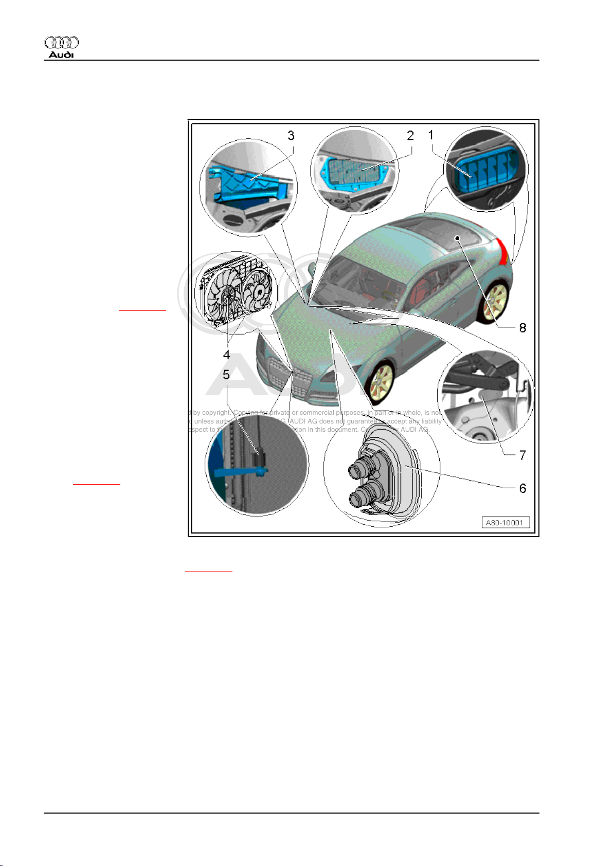
2.1 Components not located in passenger compartment
1 - Forced air extractor
❑ One forced air extractor
each is fitted on the left
and right beneath the
rear bumper.
❑ The sealing lips of the
vent frame must move
freely and close auto‐
matically.
❑ To ensure proper func‐
tioning of the passenger
compartment ventila‐
tion, the air ducts must
not be blocked by the
luggage compartment
lining.
❑ Checking ⇒ page 65
2 - Fresh-air intake grille
❑ Ensure correct position‐
ing, stops ingress of for‐
eign matter (e.g. leaves)
into the intake housing
of the heater.
❑ Check the bonded seal
for damage and proper
attachment. This seal
stops water running be‐
neath the intake grille in‐
to the intake housing of
the heater.
❑ Removing and installing
⇒ page 68
3 - Cover for fresh-air intake
❑ Check the bonded seal
for damage and proper
attachment. This seal
stops water running be‐
tween the lower frame of the windscreen and the cover into the intake housing of the heater.
❑ Removing and installing ⇒ page 68 and ⇒ General body repairs, exterior; Rep. Gr. 50
4 - Radiator fan -V7- and radiator fan 2 -V177-
❑ Different versions of the radiator fan -V7- and radiator fan 2 -V177- are fitted depending on the vehicle
equipment ⇒ Electronic parts catalogue
❑ In normal vehicle operation, the radiator fans are not actuated by the heater operating unit, Climatronic
control unit -J255- . The measured value block of the heater operating unit shows that the fans are not
being actuated; for checking refer to ⇒ "Guided fault-finding" function of vehicle diagnostic, testing and
information system VAS 5051 .
❑ The request for activation of the radiator fan(s) -V7- is only transmitted by the heater operating unit,
Climatronic control unit -J255- by way of the data bus to the engine control unit in the “Final control
diagnosis” function. With the engine running, the engine control unit then actuates the fan(s) ( radiator
fan -V7- and radiator fan 2 -V177- ) directly or by way of the radiator fan control unit -J293- ⇒ "Guided
fault-finding" function of vehicle diagnostic, testing and information system VAS 5051 and ⇒ Engine,
mechanics; Rep. Gr. 19 .
❑ With the engine running, the corresponding engine control unit switches e.g. the radiator fan -V7- and
the radiator fan 2 -V177- (directly or via the radiator fan control unit -J293- ) infinitely to the desired output
(depending on the engine type) ⇒ "Guided fault-finding" function of vehicle diagnostic, testing and in‐
formation system VAS 5051 and ⇒ Current flow diagrams, Electrical fault finding and Fitting locations.
4 Rep. Gr.80 - Heating
Page 11

Protected by copyright. Copying for private or commercial purposes, in part or in whole, is not
permitted unless authorised by AUDI AG. AUDI AG does not guarantee or accept any liability
with respect to the correctness of information in this document. Copyright by AUDI AG.
Audi TT 2007 ➤
Heating and Air Conditioning - Edition 04.2009
5 - Ambient temperature sensor -G17-
❑ The measured value of the ambient temperature sensor -G17- is not used by the heater operating unit,
Climatronic control unit -J255- for heater regulation. Its measured value is however used to calculate the
permissible ON time for the heated rear window -Z1- .
❑ The measured value of the ambient temperature sensor -G17- is evaluated by the control unit with display
in dash panel insert -J285- and transmitted by way of the convenience data bus system to the heater
operating unit, Climatronic control unit -J255- ⇒ "Guided fault-finding" function of vehicle diagnostic,
testing and information system VAS 5051 .
Removing and installing:
– Remove the bumper cover ⇒ General body repairs, exterior; Rep. Gr. 50 .
– Unplug the connector at the temperature sensor and unclip the temperature sensor from the mount in
the air duct.
6 - Connections for coolant hoses to heating system heat exchanger
❑ Detaching coolant hoses from connections to heating system heat exchanger/attaching ⇒ page 114
(removing and installing air conditioner heat exchanger)
❑ For incorporation of heating system heat exchanger into engine coolant circuit, refer to ⇒ Engine, me‐
chanics; Rep. Gr. 19 .
7 - Plenum chamber water drains
❑ One water drain each is fitted on the left and right in the plenum chamber.
❑ Removing/installing grommet, checking and cleaning ⇒ page 67 .
8 - Heated rear window -Z1-
❑ The rear window heating request is transmitted by the heater operating unit, Climatronic control unit -
J255- via the convenience data bus. The heated rear window -Z1- is actuated by way of the onboard
supply control unit -J519- ⇒ "Guided fault-finding" function of vehicle diagnostic, testing and information
system VAS 5051 and ⇒ Current flow diagrams, Electrical fault finding and Fitting locations.
❑ Notes on operation of heated rear window ⇒ page 27
❑ Removing and installing rear window ⇒ General body repairs, exterior; Rep. Gr. 64 .
2.2 Components located in passenger com‐
partment
♦ Component group “1” (components on left side) ⇒ page 6
♦ Component group “2” (components on right side)
⇒ page 8
2. Components for control and regulation of heater 5
Page 12
Protected by copyright. Copying for private or commercial purposes, in part or in whole, is not
permitted unless authorised by AUDI AG. AUDI AG does not guarantee or accept any liability
with respect to the correctness of information in this document. Copyright by AUDI AG.
Audi TT 2007 ➤
Heating and Air Conditioning - Edition 04.2009
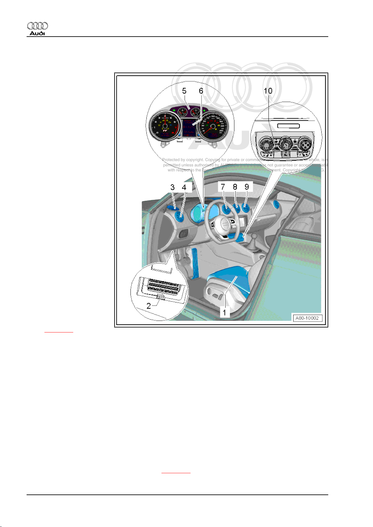
2.2.1 Component group “1” (components on left side)
1 - Front left seat temperature
sender -G344- and front left
seat heating -Z45-
❑ Not all vehicles feature
seat heating (optional
extra).
❑ Actuation of the seat
heating is indicated in
the measured value
block of the heater op‐
erating unit, Climatronic
control unit -J255- ; for
checking refer to ⇒
"Guided fault-finding"
function of vehicle diag‐
nostic, testing and infor‐
mation system
VAS 5051.
❑ Servicing seat heating
⇒ General body repairs,
interior; Rep. Gr. 74 .
2 - Diagnosis connection
❑ Heater self-diagnosis
procedure ⇒ "Guided
fault-finding" function of
vehicle diagnostic, test‐
ing and information sys‐
tem VAS 5051 .
3 - Defroster vent / left side
window
❑ Removing and installing
⇒ General body repairs,
interior; Rep. Gr. 70 .
4 - Left dash panel vent
❑ Removing and installing
dash panel vents
⇒ page 74 and ⇒ Gen‐
eral body repairs, interior; Rep. Gr. 70
5 - Control unit with display in dash panel insert -J285-
❑ With ambient temperature indicator -G106❑ The control unit with display in dash panel insert -J285- evaluates the measured value of the ambient
temperature sensor -G17- and then transmits this via the convenience data bus to the heater operating
unit, Climatronic control unit -J255- ⇒ "Guided fault-finding" function of vehicle diagnostic, testing and
information system VAS 5051 .
6 - Ambient temperature indicator -G106-
❑ The ambient temperature indicator -G106- is part of the control unit with display in dash panel insert -
J285- .
❑ The measured value of the ambient temperature sensor -G17- is evaluated by the control unit with display
in dash panel insert -J285- and transmitted by way of the convenience data bus to the heater operating
unit, Climatronic control unit -J255- ⇒ "Guided fault-finding" function of vehicle diagnostic, testing and
information system VAS 5051 .
❑ If the temperature reading is incorrect, check the measured value of the temperature sensor ⇒ "Guided
fault-finding" function of vehicle diagnostic, testing and information system VAS 5051.
7 - Centre left dash panel vent
❑ Removing and installing dash panel vents ⇒ page 74 and ⇒ General body repairs, interior; Rep. Gr.
70
6 Rep. Gr.80 - Heating
Page 13

Protected by copyright. Copying for private or commercial purposes, in part or in whole, is not
permitted unless authorised by AUDI AG. AUDI AG does not guarantee or accept any liability
with respect to the correctness of information in this document. Copyright by AUDI AG.
Audi TT 2007 ➤
Heating and Air Conditioning - Edition 04.2009
8 - Centre dash panel vent
❑ Removing and installing dash panel vents ⇒ page 74 and ⇒ General body repairs, interior; Rep. Gr.
70
9 - Centre right dash panel vent
❑ Removing and installing dash panel vents ⇒ page 74 and ⇒ General body repairs, interior; Rep. Gr.
70
10 - Heater operating unit, Climatronic control unit -J255-
❑ Different versions, with or without seat heating switch, for assignment refer to ⇒ Electronic parts cata‐
logue
❑ Vehicles with 5-cyl. engine are only to be fitted with heater operating units with part number 8J0 819 043
as of index “D” ⇒ Electronic parts catalogue and ⇒ "Guided fault-finding" function of vehicle diagnostic,
testing and information system VAS 5051 .
❑ Removing and installing ⇒ page 78 (removing and installing air conditioner operating unit, Climatronic
control unit -J255- ).
❑ The heater operating unit, Climatronic control unit -J255- has neither an integrated dash panel temper‐
ature sensor -G56- nor a temperature sensor blower -V42- .
❑ Also heed the additional notes on the air conditioner operating unit, Climatronic control unit -J255-
⇒ page 78 .
❑ Heater operating unit, Climatronic control unit -J255- self-diagnosis is to be performed as described in
the guided fault-finding routine ⇒ "Guided fault-finding" function of vehicle diagnostic, testing and infor‐
mation system VAS 5051 .
❑ The buttons and rotary controls are illuminated by LEDs which cannot be replaced separately.
❑ The function indicator lamps in the buttons and rotary controls as well as the rotary controls and buttons
cannot be replaced separately.
2. Components for control and regulation of heater 7
Page 14
Protected by copyright. Copying for private or commercial purposes, in part or in whole, is not
permitted unless authorised by AUDI AG. AUDI AG does not guarantee or accept any liability
with respect to the correctness of information in this document. Copyright by AUDI AG.
Audi TT 2007 ➤
Heating and Air Conditioning - Edition 04.2009
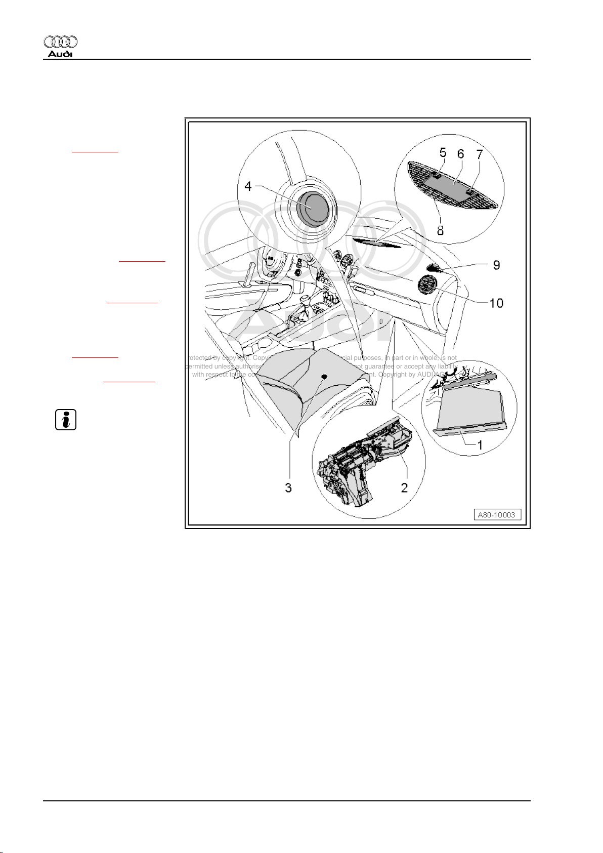
2.2.2 Component group “2” (components on right side)
1 - Dust and pollen filter
❑ Removing and installing
⇒ page 96
❑ Observe replacement
intervals ⇒ Mainte‐
nance tables
❑ Vehicles with no air con‐
ditioner (heater only)
are fitted with a dust and
pollen filter with no acti‐
vated charcoal element
⇒ Electronic parts cata‐
logue and ⇒ page 97
2 - Heater with attachments
❑ Air routing in heater and
vehicle ⇒ page 122 (air
routing is identical for
vehicles without and
with air conditioner).
❑ Heater components
⇒ page 10
❑ Removing and installing
heater ⇒ page 170 (re‐
moving and installing air
conditioner unit)
Note
3 - Front right seat temperature
sender -G345- and front right
seat heating -Z46-
❑ Not all vehicles feature
seat heating (optional
extra).
❑ Actuation of the seat
heating is indicated in
the measured value block of the heater operating unit, Climatronic control unit -J255- ; for checking refer
to ⇒ "Guided fault-finding" function of vehicle diagnostic, testing and information system VAS 5051.
❑ Servicing seat heating ⇒ General body repairs, interior; Rep. Gr. 74 .
4 - Sealing plug
❑ On vehicles with no air conditioner (heater only), the opening at the transmission tunnel for the air con‐
ditioner condensate drain must be sealed with a plug.
5 - Cap
❑ Removing and installing ⇒ General body repairs, interior; Rep. Gr. 70
❑ Vehicles with no air conditioner (heater only) are not fitted with a sunlight penetration photosensor -
G107- .
6 - Cover for centre dash panel loudspeaker
❑ Removing and installing cover ⇒ General body repairs, interior; Rep. Gr. 70
7 - Central locking system LED
❑ Removing and installing ⇒ General body repairs, interior; Rep. Gr. 70
8 - Defroster vent / windscreen
❑ Removing and installing ⇒ General body repairs, interior; Rep. Gr. 70
9 - Defroster vent / right side window
❑ Removing and installing ⇒ General body repairs, interior; Rep. Gr. 70
8 Rep. Gr.80 - Heating
Page 15

Protected by copyright. Copying for private or commercial purposes, in part or in whole, is not
permitted unless authorised by AUDI AG. AUDI AG does not guarantee or accept any liability
with respect to the correctness of information in this document. Copyright by AUDI AG.
Audi TT 2007 ➤
Heating and Air Conditioning - Edition 04.2009
10 - Right dash panel vent
❑ Removing and installing dash panel vents ⇒ page 74 and ⇒ General body repairs, interior; Rep. Gr.
70
2. Components for control and regulation of heater 9
Page 16
Protected by copyright. Copying for private or commercial purposes, in part or in whole, is not
permitted unless authorised by AUDI AG. AUDI AG does not guarantee or accept any liability
with respect to the correctness of information in this document. Copyright by AUDI AG.
Audi TT 2007 ➤
Heating and Air Conditioning - Edition 04.2009
3 Heater components
Heed the notes on control and regulation of the heater compo‐
nents ⇒ page 3 .
Note
♦
The air routing in the heater and in the vehicle is the same as
for vehicles with an air conditioner ⇒ page 122 (block diagram
of air distribution).
♦
The heater is to be removed and installed in the same manner
as the air conditioner unit ⇒ page 170 (removing and installing
air conditioner unit).
♦
The colour indicated for the levers and the connecting ele‐
ments to the various control motors applies to left-hand drive
vehicles. On right-hand drive vehicles, these components
have a different colour.
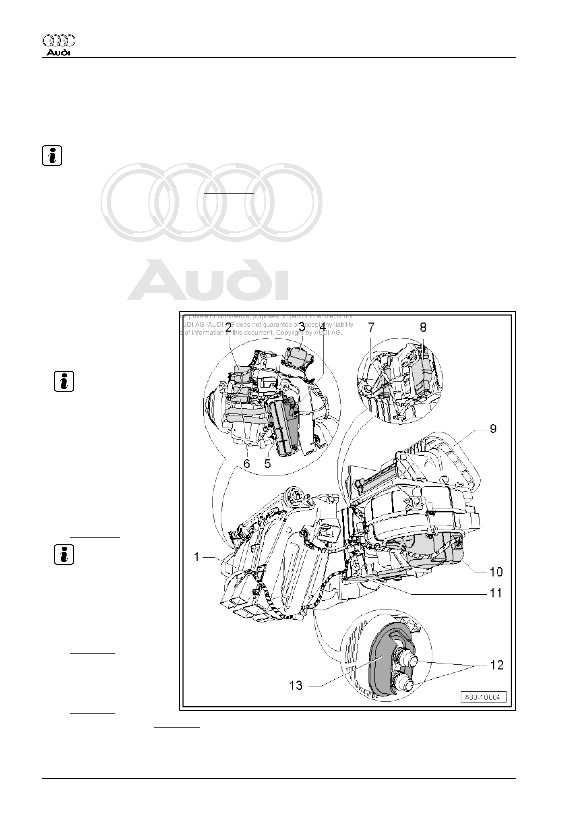
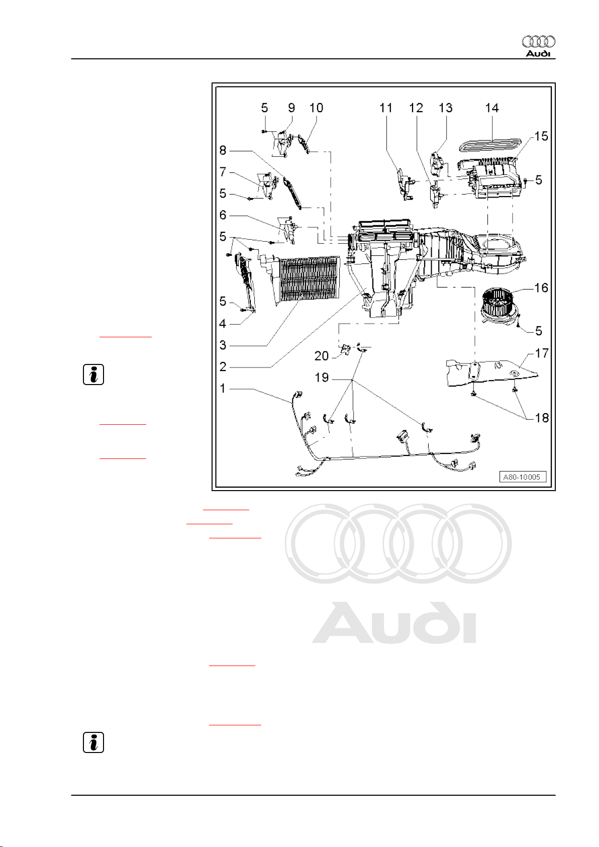
1 - Heater with attachments
❑ Removing and installing
heater ⇒ page 170 (re‐
moving and installing air
conditioner unit)
Note
❑ Dismantling and assem‐
2 - Defroster flap control motor
-V107❑ With potentiometer for
❑ Colour code for lever:
❑ Removing and installing
3 - Central flap control motor V70-
❑ With potentiometer for
❑ Removing and installing
4 - Supplementary heater ele‐
ment -Z35-
❑ Only available for vehi‐
❑ Function, checking ⇒ page 29
❑ Removing and installing ⇒ page 111
bling heater
⇒ page 16
defroster flap control
motor -G135-
blue
⇒ page 107
Note
centre flap servomotor G112-
⇒ page 91
cles with diesel engine
⇒ page 29 .
10 Rep. Gr.80 - Heating
Page 17
Protected by copyright. Copying for private or commercial purposes, in part or in whole, is not
permitted unless authorised by AUDI AG. AUDI AG does not guarantee or accept any liability
with respect to the correctness of information in this document. Copyright by AUDI AG.
Audi TT 2007 ➤
Heating and Air Conditioning - Edition 04.2009
5 - Heating system heat exchanger
❑ Removing and installing ⇒ page 114 (removing and installing heat exchanger of air conditioner unit)
6 - Left temperature flap control motor -V158-
❑ With potentiometer for left temperature flap control motor -G220❑ Colour code for lever: white
❑ Removing and installing ⇒ page 109
Note
7 - Air flow flap control motor -V71-
❑ With potentiometer for air flow flap control motor -G113❑ Removing and installing ⇒ page 101
8 - Air recirculation flap control motor -V113-
❑ With potentiometer for air recirculation flap control motor -G143❑ Removing and installing ⇒ page 89
9 - Intake housing with recirculated-air and air flow/fresh-air flap
❑ Removing and installing ⇒ page 176
10 - Fresh air blower control unit -J126- and fresh air blower -V2-
❑ Removing and installing
⇒ page 98
❑ Different versions; on the fresh air blowers -V2- fitted at the start of production, the fresh air blower control
unit -J126- and the fresh air blower -V2- form a cast assembly (cannot be replaced separately). Fresh
air blower control units -J126- and fresh air blowers -V2- which are bolted together (and can be replaced
separately) were gradually introduced in Model Year 2007 ⇒ page 98 and ⇒ Electronic parts catalogue .
❑ The fresh air blower -V2- features an integrated fresh air blower control unit -J126- . Depending on the
version, these two components can be replaced separately or only as an assembly.
❑ Checking ⇒ "Guided fault-finding" function of vehicle diagnostic, testing and information system
VAS 5051
11 - Dust and pollen filter
❑ Removing and installing ⇒ page 96
❑ Observe replacement intervals ⇒ Maintenance tables
❑ Vehicles with no air conditioner (heater only) are fitted with a dust and pollen filter with no activated
charcoal element ⇒ Electronic parts catalogue and ⇒ page 97
12 - Coolant pipes to heat exchanger
13 - Grommet
❑ For sealing the coolant pipe opening through the plenum chamber bulkhead to the engine compartment
3. Heater components 11
Page 18
Protected by copyright. Copying for private or commercial purposes, in part or in whole, is not
permitted unless authorised by AUDI AG. AUDI AG does not guarantee or accept any liability
with respect to the correctness of information in this document. Copyright by AUDI AG.
Audi TT 2007 ➤
Heating and Air Conditioning - Edition 04.2009
4 Checking actuation of temperature
flaps and heat output
Note
♦
The Audi TT with no air conditioner (heater only) is only fitted
with one temperature flap control motor. The two temperature
flaps for the left and right side are linked by way of the shaft in
the heater air distributor housing and thus moved jointly by the
left temperature flap control motor -V158- ⇒ page 16 .
♦
As vehicles with no air conditioner (heater only) have no tem‐
perature sensors, there is no regulation of the outlet temper‐
ature. The left temperature flap control motor -V158- is set by
the heater operating unit, Climatronic control unit -J255- to a
position calculated on the basis of the temperature setting at
the rotary temperature control -A- and the learnt control motor
stop values.
♦ If the coolant circuit is not completely bled after filling, air may
accumulate in the heating system heat exchanger and thus
reduce the heat output. In addition, noise may occur or com‐
plaints may be received about differences in the temperature
of the air from the driver's and front passenger's vents.
Remedy:
– Perform a lengthy test drive at high engine speed (at least 10
minutes, engine speed above 2500 rpm). In doing so, select
a low gear to prevent excessive vehicle speed.
– In the event of complaints about poor heat output at certain
engine speeds, check incorporation of the heating system
heat exchanger into the coolant circuit. If the two coolant hoses
(supply and return) from the engine have been interchanged,
coolant will flow in the wrong direction through the heat ex‐
changer ⇒ Engine, mechanics; Rep. Gr. 19 .
♦ For checking heat output and actuation of the temperature
flaps, refer to ⇒ page 12 .
4.1 Checking heat output and actuation of
temperature flaps
Special tools and workshop equipment required
♦ Vehicle diagnostic, testing and information system -VAS 5051
A- (or vehicle diagnostic and service information system -VAS
5052- )
♦ Commercially available thermometer (for temperature meas‐
urement; if applicable use thermometer with 2 probes for
simultaneous measurement of temperature e.g. on right and
left)
♦ Test requirements ⇒ page 12
♦ Checking heat output ⇒ page 13 .
4.1.1 Test requirements:
♦ Coolant circuit bled in specified manner ⇒ Engine, mechanics;
Rep. Gr. 19
♦ All air ducts, covers and seals OK and properly installed.
♦ Air flow through dust and pollen filter not impeded by contam‐
ination.
12 Rep. Gr.80 - Heating
Page 19

Protected by copyright. Copying for private or commercial purposes, in part or in whole, is not
permitted unless authorised by AUDI AG. AUDI AG does not guarantee or accept any liability
with respect to the correctness of information in this document. Copyright by AUDI AG.
Heating and Air Conditioning - Edition 04.2009
♦ Engine warm
♦ Fault memory of heater operating unit, Climatronic control unit
-J255- interrogated and erased, basic setting performed and
encoding of heater operating unit, Climatronic control unit J255- checked ⇒ "Guided fault-finding" function of vehicle
diagnostic, testing and information system VAS 5051 .
♦ Adaption of heater operating unit, Climatronic control unit -
J255- checked ⇒ "Guided fault-finding" function of vehicle
diagnostic, testing and information system VAS 5051 .
♦ Vehicle not exposed to sunlight
4.1.2 Checking heat output
– Close bonnet.
– Close the doors, windows and rear lid.
– Open all dash panel vents.
– Start heater self-diagnosis ⇒ "Guided fault-finding" function of
vehicle diagnostic, testing and information system VAS 5051 .
– Measure the ambient temperature (temperature in the work‐
shop).
– Start engine.
Audi TT 2007 ➤
4. Checking actuation of temperature flaps and heat output 13
Page 20
Protected by copyright. Copying for private or commercial purposes, in part or in whole, is not
permitted unless authorised by AUDI AG. AUDI AG does not guarantee or accept any liability
with respect to the correctness of information in this document. Copyright by AUDI AG.
Audi TT 2007 ➤
Heating and Air Conditioning - Edition 04.2009
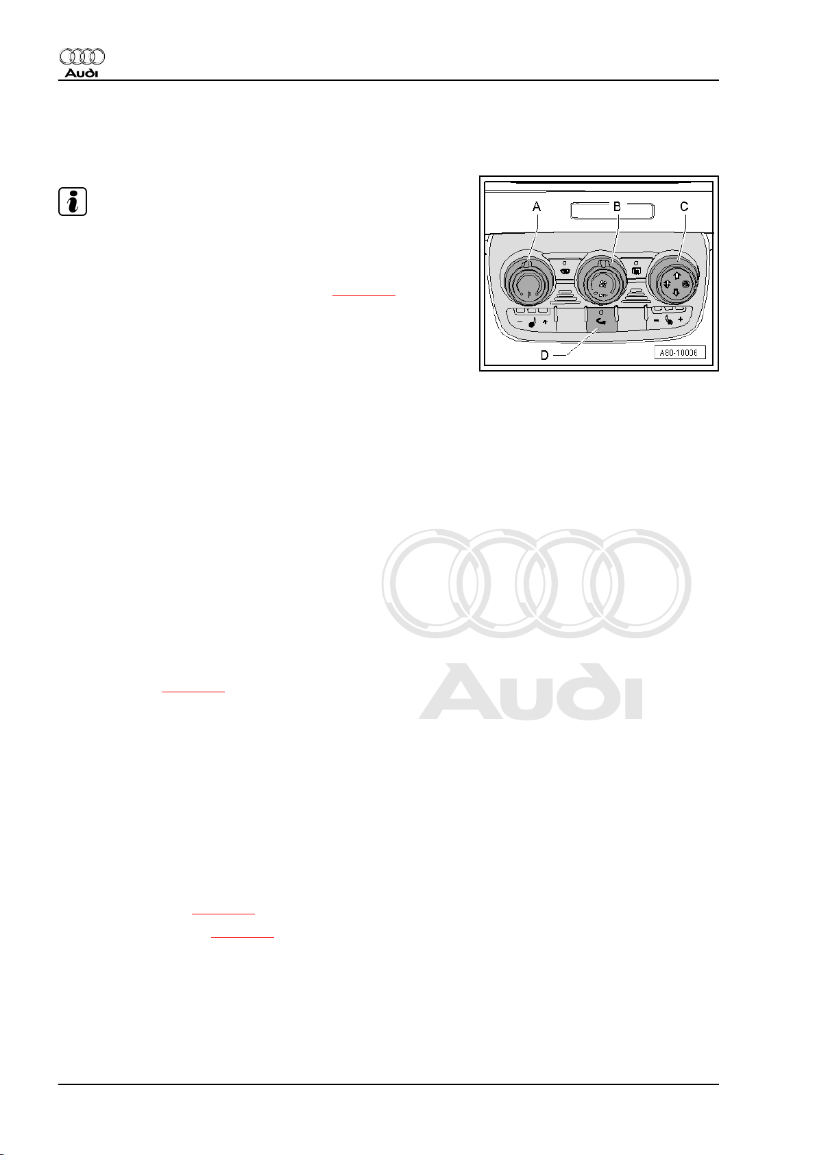
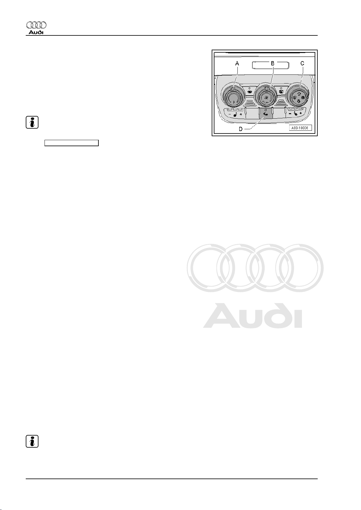
– Set the rotary temperature control -A- of the heater operating
unit, Climatronic control unit -J255- to the “cold” stop.
– Set the rotary air distribution control -C- of the heater operating
unit, Climatronic control unit -J255- such that air emerges from
the dash panel vents.
– Set the rotary fresh air blower speed control -B- of the heater
operating unit, Climatronic control unit -J255- to the “maximum
fresh air blower speed” stop.
Note
♦
The heater operates in fresh air mode, the indicator lamp in
the
recirculated air
♦
The fresh air blower runs at maximum speed.
button -D- does not light.
– Select the “Reading measured value block” function ⇒ "Gui‐
ded fault-finding" function of vehicle diagnostic, testing and
information system VAS 5051.
– Read out the measured value block with the display for the
position of the left temperature flap control motor -V158- ⇒
"Guided fault-finding" function of vehicle diagnostic, testing
and information system VAS 5051.
– Measure the temperature of the air emerging from the dash
panel vents on the left and right.
Specifications:
♦ The display shows that the left temperature flap control motor
-V158- is set to the “bottom” stop (“cold” stop).
♦ The temperature of the air emerging from the dash panel vents
on the left and right is max. 15 °C higher than the ambient
temperature previously measured (temperature increase in
heater less than 16 °C).
♦ The difference in the temperature of the air emerging from the
dash panel vents on the left and right is less than 8 °C.
– Set the rotary temperature control -A- of the heater operating
unit, Climatronic control unit -J255- to the “warm” stop.
– Read out the measured value block with the display for the
position of -V158- ⇒ "Guided fault-finding" function of vehicle
diagnostic, testing and information system VAS 5051.
– Measure the temperature of the air emerging from the dash
panel vents on the left and right.
Specifications:
♦ The display shows that the left temperature flap control motor
-V158- is set to the “top” stop (“warm” stop).
♦ The temperature of the air emerging from the dash panel vents
on the left and right increases to a value above 55 °C (at an
engine temperature of approx. 90 °C, depending on the in‐
stantaneous engine temperature).
♦ The difference in the temperature of the air emerging from the
dash panel vents on the left and right is less than 8 °C.
Note
The coolant flow through the heat exchanger (and thus the heat
output) is also governed by the engine speed.
14 Rep. Gr.80 - Heating
Page 21

Protected by copyright. Copying for private or commercial purposes, in part or in whole, is not
permitted unless authorised by AUDI AG. AUDI AG does not guarantee or accept any liability
with respect to the correctness of information in this document. Copyright by AUDI AG.
Heating and Air Conditioning - Edition 04.2009
– Set the rotary temperature control -A- of the heater operating
unit, Climatronic control unit -J255- to the “cold” stop.
– Read out the measured value block with the display for the
position of the left temperature flap control motor -V158- ⇒
"Guided fault-finding" function of vehicle diagnostic, testing
and information system VAS 5051.
– Measure the temperature of the air emerging from the dash
panel vents on the left and right.
Specifications:
♦ The display shows that the left temperature flap control motor
-V158- is set to the “bottom” stop (“cold” stop).
♦ The temperature of the air emerging from the dash panel vents
on the left and right drops within 5 minutes to a value max.15
°C higher than the ambient temperature previously measured.
Check the following if the readout does not match the specifica‐
tions:
♦ If the required heat output is not attained
– Bleeding of coolant circuit ⇒ Engine, mechanics; Rep. Gr. 19
– Incorporation of heating system heat exchanger into coolant
circuit ⇒ Engine, mechanics; Rep. Gr. 19
– Actuation and operation of the left temperature flap control
motor -V158- ⇒ "Guided fault-finding" function of vehicle di‐
agnostic, testing and information system VAS 5051.
– Foam seal for heating system heat exchanger ⇒ page 117
– Operation of temperature flaps in air distributor housing
⇒ page 124
– Thermostat (engine coolant may not warm up properly if ther‐
mostat is defective) ⇒ Engine, mechanics; Rep. Gr. 19
– Delivery of engine coolant pump ⇒ Engine, mechanics; Rep.
Gr. 19
♦ If the air emerging from the vents is too warm in the “cold”
setting
– Actuation and operation of the left temperature flap control
motor -V158- ⇒ "Guided fault-finding" function of vehicle di‐
agnostic, testing and information system VAS 5051.
– Operation of temperature flaps in air distributor housing
⇒ page 18
– The plenum chamber cover and the seal between the engine
compartment and the plenum chamber.
Audi TT 2007 ➤
4. Checking actuation of temperature flaps and heat output 15
Page 22
Protected by copyright. Copying for private or commercial purposes, in part or in whole, is not
permitted unless authorised by AUDI AG. AUDI AG does not guarantee or accept any liability
with respect to the correctness of information in this document. Copyright by AUDI AG.
Audi TT 2007 ➤
Heating and Air Conditioning - Edition 04.2009
5 Dismantling and assembling heater
Removing and installing heater ⇒ page 170 (removing and in‐
stalling air conditioner unit)
Note
The heater is to be removed in the same manner as the air con‐
ditioner unit, with the exception of the work for those components
which are only fitted with an air conditioner.
♦ Detaching electrical add-on components from heater/re-at‐
taching ⇒ page 16 .
♦ Dismantling and assembling heater ⇒ page 18
♦ Dismantling and assembling air duct ⇒ page 20
5.1 Detaching electrical add-on compo‐
nents from heater/re-attaching
Note
The colour indicated for the levers and the connecting element to
the various control motors applies to left-hand drive vehicles. On
right-hand drive vehicles, these components have a different col‐
our.
16 Rep. Gr.80 - Heating
Page 23
Protected by copyright. Copying for private or commercial purposes, in part or in whole, is not
permitted unless authorised by AUDI AG. AUDI AG does not guarantee or accept any liability
with respect to the correctness of information in this document. Copyright by AUDI AG.
1 - Heater wiring harness
❑ Different versions (e.g.
with or without power
supply for supplementa‐
ry air heater element Z35- ) ⇒ Electronic
parts catalogue
❑ Mark assignment before
unplugging connectors
(identical connectors for
different control motors,
danger of interchange).
❑ Fasten the wiring har‐
ness to the attachment
points provided on the
housing (with cable ties
or at the mounts) such
that the harness cannot
come into contact with
moving parts.
2 - Heater
❑ Removing and installing
⇒ page 170 (removing
and installing air condi‐
tioner unit)
Audi TT 2007 ➤
Heating and Air Conditioning - Edition 04.2009
Note
❑ Dismantling and assem‐
bling heater
⇒ page 18
❑ Dismantling and assem‐
bling air duct
⇒ page 20
3 - Supplementary heater ele‐
ment -Z35-
❑ Only available for vehi‐
cles with diesel engine ⇒ page 29 .
❑ Function, checking ⇒ page 29
❑ Removing and installing ⇒ page 111
4 - Cover for coolant pipes and heat exchanger
❑ This illustration shows the version for vehicles with supplementary heater element -Z35- .
❑ Different versions for vehicles with/without supplementary heater element -Z35- (on vehicles with no
supplementary heater element -Z35- , the opening for the supplementary heater element -Z35- is sealed
with this cover) ⇒ Electronic parts catalogue
5 - Bolt
6 - Central flap control motor -V70-
❑ With potentiometer for centre flap servomotor -G112❑ Removing and installing ⇒ page 91
7 - Left temperature flap control motor -V158-
❑ With potentiometer for left temperature flap control motor -G220❑ Lever colour code: white
❑ Removing and installing ⇒ page 109
Note
5. Dismantling and assembling heater 17
Page 24
Protected by copyright. Copying for private or commercial purposes, in part or in whole, is not
permitted unless authorised by AUDI AG. AUDI AG does not guarantee or accept any liability
with respect to the correctness of information in this document. Copyright by AUDI AG.
Audi TT 2007 ➤
Heating and Air Conditioning - Edition 04.2009
8 - Connecting rod to left temperature flap control motor -V158-
❑ Colour code: black
9 - Defroster flap control motor -V107-
❑ With potentiometer for defroster flap control motor -G135❑ Colour code for lever: blue
❑ Removing and installing ⇒ page 107
Note
10 - Connecting rod to defroster flap control motor -V107-
❑ Colour code: blue
11 - Cover and holder for air flow flap control motor -V71- and air recirculation flap control motor -V113-
❑ Removing and installing ⇒ page 101 (removing air recirculation flap control motor -V113- )
❑ Following installation, check both control motors held in position by this holder. Eliminate any clearance
if necessary by attaching a piece of foam to the inside of the attachment points of the holder
⇒ page 101 .
12 - Air recirculation flap control motor -V113-
❑ With potentiometer for air recirculation flap control motor -G143❑ Removing and installing ⇒ page 101
13 - Air flow flap control motor -V71-
❑ With potentiometer for air flow flap control motor -G113❑ Removing and installing
14 - Foam seal
❑ Provides seal between heater intake housing and vehicle
15 - Intake housing with recirculated-air and air flow/fresh-air flap
⇒ page 101
❑ Not to be further dismantled
❑ Removing and installing ⇒ page 176
❑ Different replacement part versions available ⇒ page 176
16 - Fresh air blower control unit -J126- and fresh air blower -V2-
❑ Removing and installing ⇒ page 98
❑ Different versions; on the fresh air blowers -V2- fitted at the start of production, the fresh air blower control
unit -J126- and the fresh air blower -V2- form a cast assembly (cannot be replaced separately). Fresh
air blower control units -J126- and fresh air blowers -V2- which are bolted together (and can be replaced
separately) were gradually introduced in Model Year 2007 ⇒ page 98 and ⇒ Electronic parts catalogue .
❑ The fresh air blower -V2- features an integrated fresh air blower control unit -J126- . Depending on the
version, these two components can be replaced separately or only as an assembly.
17 - Insulating mat
18 - Screw-type clips
19 - Cable tie
20 - Holder for wiring harness
5.2 Dismantling and assembling heater
– Remove the heater ⇒ page 170 (removing and installing air
conditioner unit).
– Detach the electrical add-on components from the heater
⇒ page 16 .
18 Rep. Gr.80 - Heating
Page 25
Protected by copyright. Copying for private or commercial purposes, in part or in whole, is not
permitted unless authorised by AUDI AG. AUDI AG does not guarantee or accept any liability
with respect to the correctness of information in this document. Copyright by AUDI AG.
Audi TT 2007 ➤
Heating and Air Conditioning - Edition 04.2009
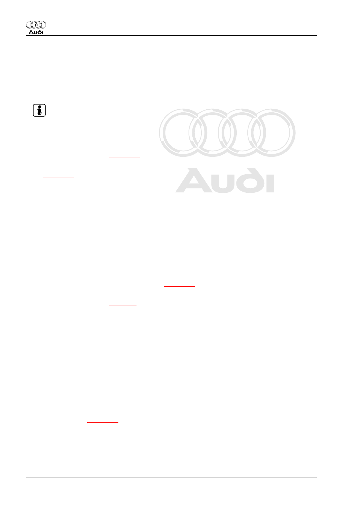
1 - Heater air distributor hous‐
ing
❑ Different versions for
heater and air condition‐
er ⇒ Electronic parts
catalogue
Note
2 - Bolt
3 - Air duct to left footwell vent
❑ Different versions ⇒
Electronic parts cata‐
logue
❑ “Heater” version (with
no opening for fitting a
temperature sensor)
4 - Heating system heat ex‐
changer
❑ Removing and installing
⇒ page 114
5 - Sealing ring
❑ Renew
❑ Moisten slightly with
coolant and fit in correct
position
6 - Clamp
❑ Renew
⇒ page 114
❑ Ensure correct position‐
ing
❑ Removing and installing
⇒ page 114
7 - Bolt
❑ Tightening torque 2.5 Nm
8 - Coolant pipes
❑ Detaching from heat exchanger/attaching ⇒ page 114
9 - Foam spacer
❑ Fitted between grommet and heater
10 - Grommet
❑ Insert in the back wall of the vehicle plenum chamber before fitting the heater ⇒ page 170
❑ Installing ⇒ page 170
11 - Air duct
❑ Dismantling and assembling air duct ⇒ page 20
12 - Dust and pollen filter
❑ Removing and installing ⇒ page 96
❑ Observe replacement intervals ⇒ Maintenance tables
❑ Vehicles with no air conditioner (heater only) are fitted with a dust and pollen filter with no activated
charcoal element ⇒ Electronic parts catalogue and ⇒ page 97
13 - Dust and pollen filter cover
❑ Removing and installing ⇒ page 96
14 - Air duct to right footwell vent
❑ Different versions ⇒ Electronic parts catalogue
5. Dismantling and assembling heater 19
Page 26
Protected by copyright. Copying for private or commercial purposes, in part or in whole, is not
permitted unless authorised by AUDI AG. AUDI AG does not guarantee or accept any liability
with respect to the correctness of information in this document. Copyright by AUDI AG.
Audi TT 2007 ➤
Heating and Air Conditioning - Edition 04.2009
❑ “Heater” version (with no opening for fitting a temperature sensor)
15 - Sealing plug
❑ Two different versions provided ⇒ page 122 .
5.3 Dismantling and assembling air duct
– Remove the heater ⇒ page 170 (removing and installing air
conditioner unit).
– Detach the electrical add-on components from the heater
⇒ page 16 .
– Dismantle the heater to the extent required ⇒ page 18 .
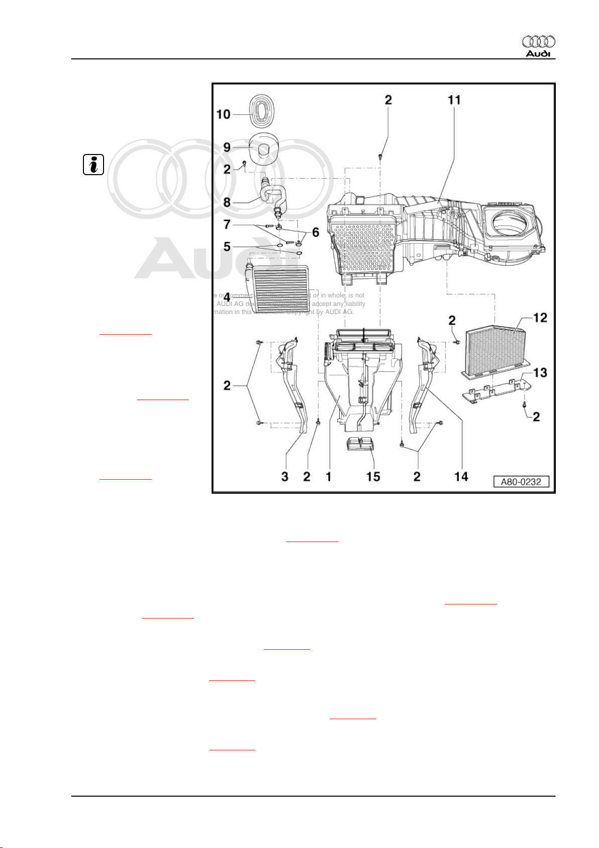
1 - Bottom part of air duct
2 - Noise insulation
❑ Vehicles with no air con‐
ditioner (heater only)
are fitted with a foam
core (for noise insula‐
tion) instead of the
evaporator.
3 - Clip
4 - Top part of air duct
5 - Bolt
20 Rep. Gr.80 - Heating
Page 27
Protected by copyright. Copying for private or commercial purposes, in part or in whole, is not
permitted unless authorised by AUDI AG. AUDI AG does not guarantee or accept any liability
with respect to the correctness of information in this document. Copyright by AUDI AG.
Heating and Air Conditioning - Edition 04.2009
87 – Air conditioning system
1 Safety measures when working on
vehicles with air conditioner and for
handling refrigerant
The air conditioner assemblies and piping system are filled with
the following refrigerant:
1.1.1.2 tetrafluoroethane (CF3-CH2F or CH2F-CF3)
This refrigerant is currently known in Germany by the trade names
R134a, H-FKW 134a, SUVA 134a and KLEA 134a (other trade
names may be used in other countries).
♦ Safety precautions ⇒ page 21 .
♦ Draining refrigerant circuit ⇒ page 22 .
♦ Working on refrigerant circuit ⇒ page 22 .
♦ Painting work on vehicles with air conditioner ⇒ page 23 .
♦ Further information on air conditioner ⇒ page 23 .
Audi TT 2007 ➤
1.1 Safety precautions
The following safety measures are to be heeded in Germany for
this refrigerant (additional regulations may apply in other coun‐
tries).
The refrigerant circuit is to be drained first should repair work re‐
quire the refrigerant circuit to be opened ⇒ page 22 . All contact
with liquid refrigerant or refrigerant vapours should be avoided.
Should refrigerant nevertheless escape, avoid inhaling the resul‐
tant refrigerant/air mixture.
Extraction systems are therefore to be switched on and use made
of both rubber gloves and safety goggles.
Explanation:
Intensive exposure to refrigerant on unprotected parts of the body
will result in frostbite.
WARNING
Keep an eye-bath to hand.
Should liquid refrigerant come into contact with the eyes, rinse
eyes thoroughly with water for approx. 15 minutes.
Then apply eye drops and consult a doctor immediately even
if no pain is felt.
Always inform doctor of the type of refrigerant involved.
Should refrigerant come into contact with other parts of the body
despite compliance with all the pertinent safety measures, these
are similarly to be rinsed thoroughly with cold water without delay
for at least 15 minutes.
Although refrigerants do not represent a fire hazard, smoking,
welding, soldering and brazing are not permitted in areas exposed
to refrigerant.
1. Safety measures when working on vehicles with air conditioner and for handling refrigerant 21
Page 28
Protected by copyright. Copying for private or commercial purposes, in part or in whole, is not
permitted unless authorised by AUDI AG. AUDI AG does not guarantee or accept any liability
with respect to the correctness of information in this document. Copyright by AUDI AG.
Audi TT 2007 ➤
Heating and Air Conditioning - Edition 04.2009
Explanation:
The high temperature of a naked flame or hot objects causes de‐
composition of refrigerant gas. Inhalation of the toxic decompo‐
sition products would cause dry coughing and nausea.
1.2 Draining refrigerant circuit
Refrigerant must not be allowed to escape into the environment.
It should be extracted from the refrigerant circuit by means of a
suction unit or an air conditioner service station. The refrigerant
removed is then either to be re-processed on site or returned to
the manufacturer for proper disposal (different or additional reg‐
ulations may apply in other countries). For this reason, the vehicle
is to be taken to a workshop equipped with the necessary tools
where the work can be performed by appropriately qualified per‐
sonnel. ⇒ Air conditioner - with refrigerant R134a
Explanation:
Should it escape into the earth's atmosphere, refrigerant R134a
will have a detrimental effect in terms of global warming.
Note
♦
Refrigerant R134a has far less of a greenhouse effect than
R12.
♦
Refrigerant R134a does not affect the earth's ozone layer
(R134a is an H-FC with no chlorine atoms). The depletion of
the ozone in the upper atmosphere is however only caused by
the splitting of carbon-chlorine bonds (as is the case, for ex‐
ample, with the refrigerant R12).
After draining the air conditioner, unplug the connector from the
air conditioner compressor regulating valve -N280- or from the
high-pressure sender -G65- .
Explanation:
The air conditioner compressor regulating valve -N280- is then no
longer actuated and the air conditioner compressor runs at idle.
The air conditioner compressor is designed such that lubrication
of the air conditioner compressor components is guaranteed by
way of an internal oil circuit at idle (provided there is sufficient
refrigerant oil in the air conditioner compressor).
1.3 Working on refrigerant circuit
Work on refrigerant circuit is only to be carried out in well venti‐
lated areas Care should be taken to ensure that there are no
inspection pits, shafts or cellar entrances within a radius of 5 me‐
tres. Extraction systems are to be switched on.
Explanation:
The refrigerant emerging is not only colourless and odourless, but
also heavier than air and thus displaces oxygen. Should refriger‐
ant gas nevertheless escape, this can result in an imperceptible
danger of asphyxiation in poorly ventilated areas and inspection
pits.
Note
The mixture of gas and air which forms when refrigerant gas es‐
capes must not be inhaled. Use is to be made of suitable work‐
shop extractors.
22 Rep. Gr.87 - Air conditioning system
Page 29

Protected by copyright. Copying for private or commercial purposes, in part or in whole, is not
permitted unless authorised by AUDI AG. AUDI AG does not guarantee or accept any liability
with respect to the correctness of information in this document. Copyright by AUDI AG.
Heating and Air Conditioning - Edition 04.2009
Welding, brazing and soldering are not permitted on sections of
the air conditioner when filled. This also applies to vehicle welding
and soldering work if there is a danger of air conditioner compo‐
nents becoming hot.
Explanation:
Exposure to heat creates considerable pressure in the system
which could cause it to burst.
Remedy:
Drain refrigerant circuit ⇒ page 22 .
Note
Damaged or leaking air conditioner components are not to be re‐
paired by welding or soldering, but should be replaced.
When servicing air conditioner, all open components and pipe
connections are to be immediately re-sealed.
Explanation:
Moisture will ingress into air conditioner components if they are
left open for a lengthy period. If this is the case, air conditioners
cannot be re-filled without having to replace parts of the system.
Audi TT 2007 ➤
1.4 Painting work on vehicles with air con‐
ditioner
When performing paintwork repairs, the temperature in the drying
booth or preheating zone must not exceed 80 °C.
Explanation:
Exposure to heat creates considerable pressure in the system
which could cause it to burst.
1.5 Further information on air conditioner
♦ The relevant current flow diagrams can be found in the Current
flow diagrams, Electrical fault-finding and Fitting locations
binder. ⇒ Current flow diagrams, Electrical fault finding and
Fitting locations
♦ A label in the engine compartment indicates the refrigerant
used as well as the capacity.
♦ For further information on repair work for vehicles fitted with
an air conditioner and on handling refrigerant, refer to ⇒ Air
conditioner with refrigerant R134a .
1. Safety measures when working on vehicles with air conditioner and for handling refrigerant 23
Page 30
Protected by copyright. Copying for private or commercial purposes, in part or in whole, is not
permitted unless authorised by AUDI AG. AUDI AG does not guarantee or accept any liability
with respect to the correctness of information in this document. Copyright by AUDI AG.
Audi TT 2007 ➤
Heating and Air Conditioning - Edition 04.2009
2 Notes on air conditioner repair work
WARNING
Remove the appropriate fuse(s) before working on wiring.
Note
Disconnect the battery -A- before starting electric welding work
on the vehicle ⇒ Electrical system; Rep. Gr. 27
It is only permissible if so required by the pertinent safety regu‐
lations ⇒ page 21 , or if parts of the air conditioner refrigerant
circuit have to be replaced, to drain and open the air conditioner
refrigerant circuit ⇒ page 22 (draining refrigerant circuit).
The air conditioner refrigerant circuit must remain closed during
all other normal vehicle repair operations.
Service work which can be performed on the heater and air con‐
ditioner without opening the refrigerant circuit is described in this
Workshop Manual ⇒ page 60 .
Note
The connections for the senders/switches described in this Work‐
shop Manual are fitted with a valve which closes automatically
when the switches are unscrewed. These switches may therefore
be renewed in any VW/Audi workshop without draining the refrig‐
erant circuit.
Air conditioner service work for which the refrigerant circuit has to
be drained and which therefore cannot be performed at all VW/
Audi workshops is described as of ⇒ page 143 . Draining of the
refrigerant circuit requires the use of specific tools and such work
is also only to be performed by qualified personnel. For this rea‐
son, it may be necessary to take the vehicle to a workshop
equipped with the necessary tools where the work can be per‐
formed by appropriately qualified personnel ⇒ Air conditioner with
refrigerant R134a .
♦ Contact corrosion ⇒ page 24
♦ Notes on air conditioner guided fault-finding ⇒ page 25
♦ Checking electrical components of air conditioner
⇒ page 25
♦ Checking of electrical components actuated by the air condi‐
tioner ⇒ page 26
2.1 Contact corrosion
Contact corrosion can occur if use is made of unsuitable con‐
necting elements, bolts, nuts, washers, rivets, plugs, grommets,
adhesives, etc.
For this reason, only connecting elements with a special surface
coating are fitted at the factory. In addition, rubber components,
plastic components and adhesives are made of non-conductive
materials. These tested, aluminium-compatible components are
also available as replacement parts ⇒ Electronic parts catalogue .
24 Rep. Gr.87 - Air conditioning system
Page 31

Protected by copyright. Copying for private or commercial purposes, in part or in whole, is not
permitted unless authorised by AUDI AG. AUDI AG does not guarantee or accept any liability
with respect to the correctness of information in this document. Copyright by AUDI AG.
Heating and Air Conditioning - Edition 04.2009
Important:
♦ Always fit new parts in cases of doubt about reusability.
♦ We recommend the use of genuine replacement parts only, as
these have been checked and are compatible with aluminium
⇒ Electronic parts catalogue .
♦ We advise using Audi accessories ⇒ Electronic parts cata‐
logue .
♦ Damage caused by contact corrosion is not covered by war‐
ranty.
2.2 Notes on air conditioner guided faultfinding
♦ There are various versions of the air conditioner operating unit,
Climatronic control unit -J255- . When renewing, observe pre‐
cise allocation. ⇒ Electronic parts catalogue
♦ Air conditioner self-diagnosis is to be performed by way of the
“Guided fault-finding” function using the vehicle diagnostic,
testing and information system ⇒ "Guided fault-finding" func‐
tion of vehicle diagnostic, testing and information system VAS
5051.
♦ At present air conditioner operating units, Climatronic control
unit -J255- can be exchanged in the familiar manner, as com‐
ponent protection is currently not active ⇒ "Guided faultfinding" function of vehicle diagnostic, testing and information
system VAS 5051 .
♦ If an air conditioner operating unit, Climatronic control unit -
J255- is to be replaced, interrogate the encoding and adaption
(of the air conditioner operating unit, Climatronic control unit J255- ) prior to removal by way of the “Control unit replace‐
ment” function ⇒ "Guided fault-finding" function of vehicle
diagnostic, testing and information system VAS 5051 .
Audi TT 2007 ➤
2.3 Checking electrical components of air conditioner
Note
♦
The “Electrical checks” function is not described in this Work‐
shop Manual. When implementing electrical checks by way of
the “Guided fault-finding” function, information is given on the
functions to be checked ⇒ "Guided fault-finding" function of
vehicle diagnostic, testing and information system VAS 5051 .
♦
The temperature-dependent resistance values of the various
temperature sensors are stored in tables which can be called
up via the “Guided fault-finding” function ⇒ "Guided fault-find‐
ing" function of vehicle diagnostic, testing and information
system VAS 5051 .
♦ Wiring and component check using test box -V.A.G 1598 A-
⇒ page 25
2.3.1 Checking wiring and components with test box -V.A.G 1598 A-
Special tools, testers and other items required
♦ Test box (basic unit) -V.A.G 1598/14- with adapter -V.A.G
1598/11- and adapter -V.A.G 1598/12-
2. Notes on air conditioner repair work 25
Page 32

Protected by copyright. Copying for private or commercial purposes, in part or in whole, is not
permitted unless authorised by AUDI AG. AUDI AG does not guarantee or accept any liability
with respect to the correctness of information in this document. Copyright by AUDI AG.
Audi TT 2007 ➤
Heating and Air Conditioning - Edition 04.2009
♦ Vehicle diagnostic, testing and information system -VAS 5051
A- with multimeter leads -VAS 5051/7- , probe -VAS 5051/8and current probe 50 A -VAS 5051/9-
♦ Voltage tester -V.A.G 1527 B-
♦ Adapter set -V.A.G 1594 C-
♦ Temperature measuring instrument (e.g. commercially avail‐
able thermometer)
♦ Current flow diagram for vehicle system to be checked ⇒ Cur‐
rent flow diagrams, Electrical fault finding and Fitting locations
Note
Electrical checking is to be performed as described in the guided
fault-finding routine ⇒ "Guided fault-finding" function of vehicle
diagnostic, testing and information system VAS 5051 .
2.4 Checking of electrical components ac‐
tuated by the air conditioner
Note
Various electrical components in the vehicle (e.g. the heated rear
window -Z1- and the heated seats), which do not form part of the
air conditioner, are actuated by the air conditioner operating unit,
Climatronic control unit -J255- . Electrical checking of these com‐
ponents is to be performed as described in the air conditioner
guided fault-finding routine ⇒ "Guided fault-finding" function of
vehicle diagnostic, testing and information system VAS 5051 .
♦ Checking of heated rear window -Z1- ⇒ page 27
♦ Checking heated seats ⇒ page 28 .
♦ Checking electric supplementary heater ⇒ page 29 .
26 Rep. Gr.87 - Air conditioning system
Page 33

Protected by copyright. Copying for private or commercial purposes, in part or in whole, is not
permitted unless authorised by AUDI AG. AUDI AG does not guarantee or accept any liability
with respect to the correctness of information in this document. Copyright by AUDI AG.
Heating and Air Conditioning - Edition 04.2009
2.4.1 Checking of heated rear window -Z1-
Note
♦
Situations preventing activation of the heated rear window
(short circuit in connection to rear window, open circuit in pow‐
er supply to air conditioner operating unit, Climatronic control
unit -J255- etc.) are stored as faults in the air conditioner op‐
erating unit, Climatronic control unit -J255- ⇒ "Guided faultfinding" function of vehicle diagnostic, testing and information
system VAS 5051.
♦
If the voltage measured at the onboard supply control unit J519- at terminal “30” drops below a value stored in the
onboard supply control unit -J519- , the heated rear window is
completely deactivated (or the power reduced) to relieve the
load on the alternator -C- (the air conditioner operating unit,
Climatronic control unit -J255- reduces the actuation duty cy‐
cle from 100% to 90 .... 0 %) ⇒ "Guided fault-finding" function
of vehicle diagnostic, testing and information system
VAS 5051.
♦
If the heated rear window has to be deactivated on account of
undervoltage, the indicator lamp in the button for the heated
rear window in the air conditioner operating unit, Climatronic
control unit -J255- remains on. However if deactivation lasts
longer than approx. 150 s, the air conditioner operating unit,
Climatronic control unit -J255- switches off the indicator lamp.
♦
The measured value block of the air conditioner operating unit,
Climatronic control unit -J255- shows that the heated rear win‐
dow is being actuated or indicates why there is no actuation
in spite of a corresponding request ⇒ "Guided fault-finding"
function of vehicle diagnostic, testing and information system
VAS 5051 .
♦
Checking of heated rear window actuation is described in the
guided fault-finding routine for the onboard supply control unit
-J519- ⇒ "Guided fault-finding" function of vehicle diagnostic,
testing and information system VAS 5051 ( -J519- actuates
the heated rear window -Z1- ).
Audi TT 2007 ➤
♦
At ambient temperatures below 0 °C, the heated rear window
remains switched on until the ignition is switched off (manual
deactivation is possible at any time). If the temperature during
a driving cycle rises above 0 °C, the heated rear window is
deactivated on completion of the operating period stored in the
air conditioner operating unit, Climatronic control unit -J255(approx. 10 minutes).
♦
At ambient temperatures above 0 °C, the heated rear window
can be deactivated automatically on completion of the oper‐
ating period stored in the air conditioner operating unit, Cli‐
matronic control unit -J255- (approx. 10 minutes) by the air
conditioner operating unit, Climatronic control unit -J255- (ac‐
tuation time is governed by encoding and version of air con‐
ditioner operating unit, Climatronic control unit -J255- ) ⇒
"Guided fault-finding" function of vehicle diagnostic, testing
and information system VAS 5051.
2. Notes on air conditioner repair work 27
Page 34

Protected by copyright. Copying for private or commercial purposes, in part or in whole, is not
permitted unless authorised by AUDI AG. AUDI AG does not guarantee or accept any liability
with respect to the correctness of information in this document. Copyright by AUDI AG.
Audi TT 2007 ➤
Heating and Air Conditioning - Edition 04.2009
2.4.2 Checking heated seats
Note
♦
Situations preventing activation of the driver's/front passeng‐
er's seat heating (short circuit in connection to seat heating
element, open circuit in power supply to air conditioner oper‐
ating unit, Climatronic control unit -J255- etc.) are stored as
faults in the air conditioner operating unit, Climatronic control
unit -J255- ⇒ "Guided fault-finding" function of vehicle diag‐
nostic, testing and information system VAS 5051.
♦
Checking of heated seat actuation is described in the air con‐
ditioner guided fault-finding routine ⇒ "Guided fault-finding"
function of vehicle diagnostic, testing and information system
VAS 5051 .
♦
If the voltage measured at the onboard supply control unit J519- at terminal “30” drops below a value stored in -J519- ,
the seat heating power is reduced (currently to approx. 50 %)
or the heating function is completely deactivated to relieve the
load on the alternator -C- . The air conditioner operating unit,
Climatronic control unit -J255- reduces the actuation duty cy‐
cle from 100 % to less than 90 ... 0 % ⇒ "Guided fault-finding"
function of vehicle diagnostic, testing and information system
VAS 5051 .
♦
The measured value block of the air conditioner operating unit,
Climatronic control unit -J255- shows that the front seat heat‐
ing is being actuated or indicates why there is no actuation in
spite of a corresponding request ⇒ "Guided fault-finding"
function of vehicle diagnostic, testing and information system
VAS 5051 .
28 Rep. Gr.87 - Air conditioning system
Page 35

Protected by copyright. Copying for private or commercial purposes, in part or in whole, is not
permitted unless authorised by AUDI AG. AUDI AG does not guarantee or accept any liability
with respect to the correctness of information in this document. Copyright by AUDI AG.
Heating and Air Conditioning - Edition 04.2009
2.4.3 Checking electric supplementary heater
The supplementary heater element -Z35- is only installed on ve‐
hicles with diesel engine.
Note
♦
An electric supplementary air heater is currently fitted on ve‐
hicles with diesel engine ⇒ Audi sales range . Heat energy is
supplied to the air after leaving the heat exchanger of the air
conditioner unit in the event of a request from the air condi‐
tioner operating unit, Climatronic control unit -J255- .
♦
The electric supplementary heater ( supplementary air heater
element -Z35- ) is actuated by way of the corresponding en‐
gine control unit (the control units exchange the appropriate
information by way of the data bus) ⇒ "Guided fault-finding"
function of vehicle diagnostic, testing and information system
VAS 5051 and ⇒ Current flow diagrams, Electrical fault finding
and Fitting locations.
♦
The measured value block of the air conditioner operating unit,
Climatronic control unit -J255- shows that the electric supple‐
mentary heater is being actuated or indicates why there is no
actuation in spite of a low ambient temperature ⇒ "Guided
fault-finding" function of vehicle diagnostic, testing and infor‐
mation system VAS 5051 .
♦
Vehicles with petrol engine are currently not fitted with a sup‐
plementary heater.
♦
For checking actuation of the supplementary air heater ele‐
ment -Z35- , refer to the guided fault-finding routine for the
engine fitted in this vehicle ⇒ "Guided fault-finding" function
of vehicle diagnostic, testing and information system
VAS 5051 .
♦
For checking the resistance value of the supplementary air
heater element -Z35- , refer to ⇒ "Guided fault-finding" func‐
tion of vehicle diagnostic, testing and information system
VAS 5051.
Audi TT 2007 ➤
Cut-in criteria for actuation of supplementary heater
Note
On vehicles with air conditioner (or with heater only), the cut-in
criteria must be satisfied in the air conditioner (heater) operating
unit, Climatronic control unit -J255- and in the corresponding en‐
gine control unit.
– The following prerequisites must be met for the air conditioner
(heater) operating unit, Climatronic control unit -J255- to trans‐
mit a request for supplementary heater activation to the engine
control unit:
♦ Engine running for at least 8 seconds and engine speed higher
than 500 rpm.
♦ Engine temperature less than 75 °C.
♦ Calculated ambient temperature less than 8 °C.
♦ Electrical system voltage greater than 12.2 V and onboard
supply control unit -J519- not transmitting any request pre‐
venting activation.
♦ No faults stored in air conditioner (heater) operating unit, Cli‐
matronic control unit -J255- .
2. Notes on air conditioner repair work 29
Page 36

Protected by copyright. Copying for private or commercial purposes, in part or in whole, is not
permitted unless authorised by AUDI AG. AUDI AG does not guarantee or accept any liability
with respect to the correctness of information in this document. Copyright by AUDI AG.
Audi TT 2007 ➤
Heating and Air Conditioning - Edition 04.2009
♦ No faults stored in engine control unit and capacity utilisation
of alternator -C- less than 30 ... 77 % (depending on engine
speed).
♦ On the basis of the setting and the temperatures measured,
the air conditioner (heater) operating unit, Climatronic control
unit -J255- has calculated that additional heat output is re‐
quired to attain the specified passenger compartment temper‐
ature.
♦ The air conditioner (heater) operating unit, Climatronic control
unit -J255- has calculated that more than 90 % of the air is
being routed through the heat exchanger of the air conditioner
unit.
Note
On vehicles with 3-stage supplementary air heater elements Z35- , the engine control unit actuates the two supplementary
heating relays such that the capacity utilisation of the alternator C- does not exceed 95 % ⇒ "Guided fault-finding" function of
vehicle diagnostic, testing and information system VAS 5051 (for
the engine control unit) and ⇒ Current flow diagrams, Electrical
fault finding and Fitting locations. The next stage is only switched
in if the capacity utilisation of the alternator -C- is less than 30 ...
77 % depending on engine speed.
Shutoff criteria for actuation of supplementary heater
Note
Deactivation takes place as soon as a cut-in criterion is no longer
satisfied in the air conditioner (heater) operating unit, Climatronic
control unit -J255- and the corresponding engine control unit or if
one of the shutoff criteria is detected.
– The air conditioner (heater) operating unit, Climatronic control
unit -J255- cancels the request for activation of the electric
supplementary heater if:
♦ One of the cut-in prerequisites is no longer satisfied.
♦ The calculated ambient temperature is greater than 11 °C.
♦ The capacity utilisation of the alternator -C- is greater than 95
%.
♦ The air conditioner (heater) operating unit, Climatronic control
unit -J255- has calculated that less than 60 % of the air is being
routed through the heat exchanger of the air conditioner unit
(heater) (position of temperature flaps).
30 Rep. Gr.87 - Air conditioning system
Page 37

Protected by copyright. Copying for private or commercial purposes, in part or in whole, is not
permitted unless authorised by AUDI AG. AUDI AG does not guarantee or accept any liability
with respect to the correctness of information in this document. Copyright by AUDI AG.
Heating and Air Conditioning - Edition 04.2009
3 Servicing work on refrigerant circuit
Note
♦
Servicing work on refrigerant circuit ⇒ page 143
♦
All parts/operations marked
performed in any workshop (work not involving the refrigerant
circuit).
♦
All parts/operations not marked 1), as well as all refrigerant
hoses and refrigerant pipes, can only be serviced or replaced/
performed at workshops equipped with the necessary tools
where the work can be carried out by appropriately qualified
personnel (the refrigerant circuit has to be drained) ⇒ Air con‐
ditioner with refrigerant R134a .
♦ ⇒ “3.1 Exploded view of refrigerant circuit components”, page
31
3.1 Exploded view of refrigerant circuit com‐
ponents
1)
can be serviced and replaced/
Audi TT 2007 ➤
HD = High-pressure side
ND = Low-pressure side
3. Servicing work on refrigerant circuit 31
Page 38

Protected by copyright. Copying for private or commercial purposes, in part or in whole, is not
permitted unless authorised by AUDI AG. AUDI AG does not guarantee or accept any liability
with respect to the correctness of information in this document. Copyright by AUDI AG.
Audi TT 2007 ➤
Heating and Air Conditioning - Edition 04.2009
1 - Air conditioner compressor
regulating valve -N280-
❑ Checking actuation and
operation ⇒ page 45
1)
2 - Air conditioner compressor
❑ Detaching air condition‐
er compressor from
holder/re-attaching (ve‐
hicles with 4 or 6-cyl. en‐
gine) ⇒ page 40
1)
❑ Detaching air condition‐
er compressor from
holder/re-attaching (ve‐
hicles with 5-cyl. en‐
gine) ⇒ page 43
1)
❑ When installing the re‐
frigerant pipes and the
corresponding holder,
make sure there is suffi‐
cient distance between
the belt, holder and pul‐
ley.
❑ Type of compressor
may differ depending on
production period and
engine. ⇒ Electronic
parts catalogue
❑ The air conditioner com‐
pressors fitted at the
start of production are
manufactured by
“Denso” (type “6 SEU
14”). At a later date, oth‐
er makes of air condi‐
tioner compressor may
also be installed (e.g.
“Sanden”, type “PXE
16” or “ZJX”) ⇒ Elec‐
tronic parts catalogue and ⇒ Air conditioner with refrigerant R134a .
❑ Air conditioner compressors are available as replacement parts with different oil capacities and attention
must therefore be paid to the oil quantity in the air conditioner compressor as well as the exact part
number ⇒ Electronic parts catalogue .
❑ There may be different refrigerant oil capacities for the refrigerant circuit depending on the type of air
conditioner compressor. The reason for the different oil quantities in the air conditioner compressor for
an otherwise identical refrigerant circuit is the design of the actual air conditioner compressor. Attention
is to be paid to these oil quantities. Too much oil in the circuit results in higher pressures and reduced
system cooling output. Too little oil may lead to lubrication problems in the air conditioner compressor.
3 - Pulley
❑
Replace 1) ⇒ page 48
❑
Removing and installing poly V-belt 1) ⇒ Engine, mechanics; Rep. Gr. 13
❑ Poly V-belt assignment: ⇒ Electronic parts catalogue
Note
4 - Oil drain plug
5 - Pressure relief valve
6 - Connection with valve
7 - High-pressure sender -G65-
1)
❑ Removing and installing ⇒ page 33
32 Rep. Gr.87 - Air conditioning system
Page 39

Protected by copyright. Copying for private or commercial purposes, in part or in whole, is not
permitted unless authorised by AUDI AG. AUDI AG does not guarantee or accept any liability
with respect to the correctness of information in this document. Copyright by AUDI AG.
Audi TT 2007 ➤
Heating and Air Conditioning - Edition 04.2009
❑ Checking signal ⇒ page 35
8 - Condenser
9 - Receiver
❑ The receiver is attached directly to the condenser.
10 - Service connection on high-pressure end
❑ Different versions (with primary sealing valve or Schrader valve) depending on refrigerant pipe; distin‐
guishing features ⇒ Air conditioner with refrigerant R134a
❑ For air conditioner service station for measuring pressure and draining and filling refrigerant circuit ⇒ Air
conditioner with refrigerant R134a
❑ Depending on the engine version, certain components (e.g. ACF) may have to be removed for connection
of the service coupling.
WARNING
The refrigerant circuit
must be drained before
removing the service
connections (the con‐
nection has no valve).
11 - Cap
❑ With seal
❑ Always to be screwed on
12 - Expansion valve
13 - Evaporator
14 - Service connection on low-pressure end
❑ Different versions (with primary sealing valve or Schrader valve) depending on refrigerant pipe; distin‐
guishing features ⇒ Air conditioner with refrigerant R134a
❑ For air conditioner service station for measuring pressure and draining refrigerant circuit ⇒ Air conditioner
with refrigerant R134a
❑ Depending on the engine version, certain components (e.g. ACF) may have to be removed for connection
of the service coupling.
WARNING
The refrigerant circuit
must be drained before
removing the service
connections (the con‐
nection has no valve).
15 - Cap
❑ With seal
❑ Always to be screwed on
3.2 Removing and installing high-pressure sender -G65-
Special tools and workshop equipment required
3. Servicing work on refrigerant circuit 33
Page 40

Protected by copyright. Copying for private or commercial purposes, in part or in whole, is not
permitted unless authorised by AUDI AG. AUDI AG does not guarantee or accept any liability
with respect to the correctness of information in this document. Copyright by AUDI AG.
Audi TT 2007 ➤
Heating and Air Conditioning - Edition 04.2009
♦ Assembly tool -T10118-
Note
♦
The cooling output cannot be checked with the high-pressure
sender -G65- removed; the air conditioner operating unit, Cli‐
matronic control unit -J255- does not switch on the air condi‐
tioner compressor.
♦
The refrigerant circuit remains closed (connection with valve).
♦
Checking operation of high-pressure sender -G65- and signal
supplied ⇒ page 37 .
♦
Removal and installation are described in the following on the
basis of a vehicle with a 2.0 l TFSI engine and one with a 3.2
l MPI engine. The procedure may differ for vehicles with a dif‐
ferent engine (4, 5 or 6-cylinder engine).
♦
After switching off the air conditioner compressor, a relatively
long period may elapse with this vehicle before the pressure
on the high-pressure end decreases (the expansion valve is
cold and the pressure on the low-pressure end increases rap‐
idly after switch-off, the expansion valve closes and the refrig‐
erant can only flow slowly to the low-pressure end).
♦
Depending on the version of the high-pressure sender -G65- ,
the measured value for the pressure in the refrigerant circuit
transmitted by the high-pressure sender -G65- may be too low
at low ambient temperatures (ambient temperature less than
5 °C) although the air conditioner is OK and the refrigerant
circuit has been properly charged. With air conditioner oper‐
ating units, Climatronic control unit -J255- with part number
“8J0 820 043” up to index “AJ”, this may therefore erroneously
lead to a fault memory entry at ambient temperatures below
5 °C (fault memory entry: High-pressure sender -G65- “Lower
limit value not reached”). If the fault is only displayed as a
sporadic fault at ambient temperatures calculated by the air
conditioner of above 5 °C and the air conditioner is functioning
properly, the fault memory entry can be erased (no further ac‐
tion is necessary). This fault no longer occurs with air condi‐
tioner operating units, Climatronic control unit -J255- with part
number “8J0 820 043” as of index “AK”.
Removing
The high-pressure sender -G65- is located at the bottom right of
the condenser.
Note
Depending on the version, it is fitted directly at the condenser or
at the refrigerant pipe.
34 Rep. Gr.87 - Air conditioning system
Page 41

Protected by copyright. Copying for private or commercial purposes, in part or in whole, is not
permitted unless authorised by AUDI AG. AUDI AG does not guarantee or accept any liability
with respect to the correctness of information in this document. Copyright by AUDI AG.
Heating and Air Conditioning - Edition 04.2009
– Detach the poly V-belt from the alternator ⇒ Engine, mechan‐
ics; Rep. Gr. 13 (vehicles with 4-cylinder engine only).
– Screw out the bolts -arrows- and detach the air duct (vehicles
with 6-cylinder engine only).
WARNING
If the engine is warm, the radiator fan(s) -V7- may start up,
danger of injury.
Audi TT 2007 ➤
– Unplug the connector -A-.
– Unscrew the high-pressure sender -G65- -B- from the con‐
nection (at the condenser/at the refrigerant pipe).
Installing
• Tightening torque of high-pressure sender -G65- : 8 Nm.
Install in reverse order, paying attention to the following:
– Replace the O-ring -C- ⇒ page 39 . For assignment, refer to
⇒ Electronic parts catalogue .
– Secure the high-pressure sender -G65- .
– Position the poly V-belt on the poly V-belt pulleys ⇒ Engine,
mechanics; Rep. Gr. 13 (vehicles with 4-cylinder engine only).
3.3 Checking pressure signal from highpressure sender -G65-
Special tools and workshop equipment required
♦ Assembly tool -T10118-
3. Servicing work on refrigerant circuit 35
Page 42

Protected by copyright. Copying for private or commercial purposes, in part or in whole, is not
permitted unless authorised by AUDI AG. AUDI AG does not guarantee or accept any liability
with respect to the correctness of information in this document. Copyright by AUDI AG.
Audi TT 2007 ➤
Heating and Air Conditioning - Edition 04.2009
Note
♦
The cooling output cannot be checked with the high-pressure
sender -G65- removed; the air conditioner operating unit, Cli‐
matronic control unit -J255- does not switch on the air condi‐
tioner compressor ⇒ "Guided fault-finding" function of vehicle
diagnostic, testing and information system VAS 5051 .
♦
After switching off the air conditioner compressor, a relatively
long period may elapse with this vehicle before the pressure
on the high-pressure end decreases (the expansion valve is
cold and the pressure on the low-pressure end increases rap‐
idly after switch-off, the expansion valve closes and the refrig‐
erant can only flow slowly to the low-pressure end).
♦
Depending on the version of the high-pressure sender -G65- ,
the measured value for the pressure in the refrigerant circuit
transmitted by the high-pressure sender -G65- may be too low
at low ambient temperatures (ambient temperature less than
5 °C) although the air conditioner is OK and the refrigerant
circuit has been properly charged. With air conditioner oper‐
ating units, Climatronic control unit -J255- with part number
“8J0 820 043” up to index “AJ”, this may therefore erroneously
lead to a fault memory entry at ambient temperatures below
5 °C (fault memory entry: High-pressure sender -G65- “Lower
limit value not reached”). If the fault is only displayed as a
sporadic fault at ambient temperatures calculated by the air
conditioner of above 5 °C and the air conditioner is functioning
properly, the fault memory entry can be erased (no further ac‐
tion is necessary). This fault no longer occurs with air condi‐
tioner operating units, Climatronic control unit -J255- with part
number “8J0 820 043” as of index “AK”.
Test sequence
The high-pressure sender -G65- -Item B- is located at the bottom
right of the condenser.
– Unplug the connector -A-.
Assignment of 3-pin connector at high-pressure sender -G65-
1 - Earth
2 - Signal output - square-wave signal to air conditioner oper‐
ating unit, Climatronic control unit -J255-
3 - Terminal “75” (positive)
Note
♦
The air conditioner compressor is not switched on if the con‐
nector -A- is unplugged.
♦
The high-pressure sender -G65- -B- is an electronic control
unit which generates a square-wave signal with a ratio which
varies with the pressure in the refrigerant circuit
⇒ page 37 .
♦ Pressure signal from high-pressure sender -G65-
⇒ page 37
36 Rep. Gr.87 - Air conditioning system
Page 43

Protected by copyright. Copying for private or commercial purposes, in part or in whole, is not
permitted unless authorised by AUDI AG. AUDI AG does not guarantee or accept any liability
with respect to the correctness of information in this document. Copyright by AUDI AG.
Heating and Air Conditioning - Edition 04.2009
3.3.1 Pressure signal from high-pressure sender -G65-
-A- Pressure in high-pressure side of refrigerant circuit in bar (ab‐
solute)
-B- Ratio of square-wave signal.
-C- Characteristic curve.
Audi TT 2007 ➤
3. Servicing work on refrigerant circuit 37
Page 44

Protected by copyright. Copying for private or commercial purposes, in part or in whole, is not
permitted unless authorised by AUDI AG. AUDI AG does not guarantee or accept any liability
with respect to the correctness of information in this document. Copyright by AUDI AG.
Audi TT 2007 ➤
Heating and Air Conditioning - Edition 04.2009
Note
♦
As soon as there is no compressor shut-off criterion, the air
conditioner operating unit, Climatronic control unit -J255switches on the air conditioner compressor (by actuating the
air conditioner compressor regulating valve -N280- ) ⇒ "Gui‐
ded fault-finding" function of vehicle diagnostic, testing and
information system VAS 5051.
♦
If no other shut-off criterion is active, the air conditioner oper‐
ating unit, Climatronic control unit -J255- switches on the air
conditioner compressor if the signal ratio is greater than ap‐
prox. 12 % (corresponding to approx. 1.2 bar absolute) and
less than approx. 78 % (corresponding to approx. 32 bar ab‐
solute).
♦
If the signal ratio is less than 12 % or greater than 78 %, the
air conditioner compressor is not switched on (the air condi‐
tioner compressor regulating valve -N280- is not actuated).
♦
The signal ratio and the pressure calculated by the air condi‐
tioner operating unit, Climatronic control unit -J255- are indi‐
cated in the measured value block ⇒ "Guided fault-finding"
function of vehicle diagnostic, testing and information system
VAS 5051 .
♦
At absolute pressure, 0 bar corresponds to an absolute vac‐
uum. Normal ambient pressure thus corresponds to roughly 1
bar absolute. On the scales of most pressure gauges, 0 bar
corresponds to an absolute pressure of one bar (can be seen
from -1 mark below 0).
♦
Depending on the pressure calculated in the refrigerant circuit
with the air conditioner compressor actuated, the air condi‐
tioner operating unit, Climatronic control unit -J255- transmits
a request by way of the data bus for increased radiator fan V7- speed to the engine control unit, which then actuates the
radiator fan(s) -V7- either directly or via the radiator fan control
unit -J293- (at a certain pressure in the refrigerant circuit or as
soon as the air conditioner compressor is switched on irre‐
spective of the pressure, depending on the version). The
request from the air conditioner operating unit, Climatronic
control unit -J255- is displayed in the measured value block ⇒
"Guided fault-finding" function of vehicle diagnostic, testing
and information system VAS 5051 .
♦
At present, the request for actuation of the radiator fan(s) -V7is only transmitted on the data bus by the air conditioner
operating unit, Climatronic control unit -J255- as of a specific
pressure in the refrigerant circuit. If the pressure in the refrig‐
erant circuit is greater than approx. 9 bar (6 bar, if the pressure
was previously in excess of 9 bar) and less than approx. 20
bar, between 30 and 100 % is requested depending on the
pressure.
♦
If the pressure in the refrigerant circuit is less than approx. 9
bar (6 bar if the pressure was previously in excess of 9 bar),
actuation of the radiator fan(s) -V7- is currently not requested
by the air conditioner operating unit, Climatronic control unit J255- .
♦
If the pressure in the refrigerant circuit is greater than approx.
20 bar, 100 % actuation of the radiator fan(s) -V7- is requested
at present by the air conditioner operating unit, Climatronic
control unit -J255- (the actual actuation may however be less
than 100 % depending on the version of the engine control
unit/ radiator fan control unit -J293- ).
♦
The signal generated by the high-pressure sender -G65- is
also used for engine control. The air conditioner operating unit,
Climatronic control unit -J255- transmits the information via
the data bus to the engine control unit (the torque required for
driving the air conditioner compressor is governed by the pres‐
38 Rep. Gr.87 - Air conditioning system
sure in the refrigerant circuit). Depending on the version of the
engine control unit, the signal is displayed there as a ratio in
the measured value block ⇒ "Guided fault-finding" function of
vehicle diagnostic, testing and information system VAS 5051
Page 45

Protected by copyright. Copying for private or commercial purposes, in part or in whole, is not
permitted unless authorised by AUDI AG. AUDI AG does not guarantee or accept any liability
with respect to the correctness of information in this document. Copyright by AUDI AG.
Heating and Air Conditioning - Edition 04.2009
This pattern will appear on the oscilloscope screen (e.g. on the
vehicle diagnostic, testing and information system -VAS 5051 A- )
if the following conditions are satisfied.
– Ignition on (positive at contact “3” and earth at contact “1” at
high-pressure sender -G65- )
– Setting on oscilloscope: 5 V/div. DC (5 V per unit DC voltage)
5 ms/div. (5 milliseconds per unit)
– Test lead (signal wire) connected to contact “2” at high-pres‐
sure sender -G65- .
– Test lead (screen) connected to contact “1” (earth at high-
pressure sender -G65- ).
Note
♦
The illustration shows the signal transmitted at a refrigerant
circuit pressure of approx. 7 bar absolute, corresponding to a
signal ratio of approx. 25 % (level occurring with air conditioner
compressor not running, ambient temperature of 30 °C and
refrigerant circuit charged).
♦
Pulse width -A- is governed by pressure in refrigerant circuit
(area -A- becomes broader as pressure increases).
♦
The signal distance -B- is always 20 milliseconds (correspond‐
ing to a frequency of 50 hertz).
♦
The duty cycle is derived from the ratio of pulse width -A- to
signal distance -B-.
♦
Test leads from the adapter set -V.A.G 1594/C- can be em‐
ployed for example for this test or an adapter lead can be
made. For this, use one connector -A- and -B- each (with part
number 1J0 973 703 and 1J0 973 803 and the corresponding
plug contacts), two commercially available sockets for banana
plugs -C- and three wires with a cross section of 0.5 mm2 for
example.
Audi TT 2007 ➤
3.4 O-ring seals for refrigerant circuit
♦ O-ring seals are only ever to be used once and then replaced.
♦ Coat O-ring seals with refrigerant oil before fitting.
♦ Pay attention to correct positioning of O-ring seals on pipe or
in groove.
♦ Ensure absolute cleanliness when working (even the slightest
contamination, e.g. a single hair, could cause leakage).
Note
♦
Only O-ring seals which are resistant to the refrigerant R134a
and the corresponding refrigerant oil may be installed. Such
O-rings are colour coded to prevent mix-ups (currently “red”,
“lilac” or “violet”) ⇒ Electronic parts catalogue .
♦
Dimensions -a- and -b- differ depending on the fitting location
of the O-ring: ⇒ Electronic parts catalogue
♦
In addition to the coloured O-ring seals, black O-ring seals are
also used at the factory for certain connections.
3. Servicing work on refrigerant circuit 39
Page 46

Protected by copyright. Copying for private or commercial purposes, in part or in whole, is not
permitted unless authorised by AUDI AG. AUDI AG does not guarantee or accept any liability
with respect to the correctness of information in this document. Copyright by AUDI AG.
Audi TT 2007 ➤
Heating and Air Conditioning - Edition 04.2009
3.5 Detaching air conditioner compressor from holder/attaching (vehicles with 4 or 6-cyl. engine)
Note
♦
The air conditioner compressor can be detached from the
holder and re-attached without opening up the refrigerant
pipes.
♦
Detaching and attaching the air conditioner compressor are
described in the following for a vehicle with a 2.0 l TFSI engine
and a 3.2 l MPI engine, each with a “Denso” air conditioner
compressor of type “6 SEU 14”. There may be differences for
vehicles with other engines or a different air conditioner com‐
pressor (depending on the engine, it may also be necessary
to remove or unfasten certain ancillaries).
♦
Do not drain the refrigerant circuit, do not detach refrigerant
hoses and refrigerant pipes from the air conditioner compres‐
sor.
♦
Do not unfasten the refrigerant pipes and the corresponding
clamps.
♦
After detaching the air conditioner compressor, secure it with
a piece of wire for example to the vehicle. Do not leave it sus‐
pended from the refrigerant pipes ⇒ page 44
♦
Before removal, mark direction of rotation of poly V-belt with
chalk or felt-tipped pen. Running a used belt in the opposite
direction could destroy it.
♦
Different air conditioner compressors may be fitted depending
on the engine and country version ⇒ Electronic parts cata‐
logue
Special tools and workshop equipment required
♦ Torque wrench -V.A.G 1331/- (5 - 50 Nm)
40 Rep. Gr.87 - Air conditioning system
Page 47

Protected by copyright. Copying for private or commercial purposes, in part or in whole, is not
permitted unless authorised by AUDI AG. AUDI AG does not guarantee or accept any liability
with respect to the correctness of information in this document. Copyright by AUDI AG.
Heating and Air Conditioning - Edition 04.2009
♦ Locking pin -T10060 A-
Detaching
– Remove the upper engine cover ⇒ Engine, mechanics; Rep.
Gr. 13 (e.g. on vehicle with 2.0 l TFSI engine).
– Mark the direction of the poly V-belt (the illustration shows the
layout for a 4-cyl. engine).
– Detach the poly V-belt ⇒ Engine, mechanics; Rep. Gr. 13 .
– Remove the centre noise insulation ⇒ General body repairs,
exterior; Rep. Gr. 66 .
– Remove the right noise insulation ⇒ General body repairs,
exterior; Rep. Gr. 66 (e.g. on vehicle with 2.0 l TFSI engine).
– If applicable, remove the noise insulation frame (currently fit‐
ted for example on the Audi TT Roadster) ⇒ General body
repairs, exterior; Rep. Gr. 50 .
– Remove the right air hose (from air pipe between turbocharger
and charge air cooler) ⇒ Engine, mechanics; Rep. Gr. 21 (e.g.
on vehicle with TFSI engine).
Audi TT 2007 ➤
– Unplug the connector -1- at the air conditioning system com‐
pressor regulating valve -N280- .
– Screw out the bolts -arrow- for the air conditioner compressor.
– Detach the air conditioner compressor and attach it to the ve‐
hicle with a piece of wire for example ⇒ page 44
Attaching
Install in reverse order, paying attention to the following:
3. Servicing work on refrigerant circuit 41
Page 48

Protected by copyright. Copying for private or commercial purposes, in part or in whole, is not
permitted unless authorised by AUDI AG. AUDI AG does not guarantee or accept any liability
with respect to the correctness of information in this document. Copyright by AUDI AG.
Audi TT 2007 ➤
Heating and Air Conditioning - Edition 04.2009
– Before securing the air conditioner compressor, check the po‐
sition of both dowel sleeves -arrows- in the holder or air
conditioner compressor.
Note
The version of the air conditioner compressor with pulley shown
in this illustration is not installed on the Audi TT.
– Tighten the bolts -arrows- (tightening torque: 25 Nm).
– Plug in the connector -1- at the air conditioning system com‐
pressor regulating valve -N280- .
– Position the poly V-belt on the poly V-belt pulleys ⇒ Engine,
mechanics; Rep. Gr. 13 .
Note
♦
After attaching the air conditioner compressor, check the rout‐
ing of the refrigerant pipes. They must be inserted in the
holders provided (if fitted, depends on engine).
♦
Check the refrigerant pipes and the corresponding holders for
adequate clearance with respect to the other components, en‐
suring a sufficient distance between the belt, holder and pul‐
ley.
42 Rep. Gr.87 - Air conditioning system
Page 49

Protected by copyright. Copying for private or commercial purposes, in part or in whole, is not
permitted unless authorised by AUDI AG. AUDI AG does not guarantee or accept any liability
with respect to the correctness of information in this document. Copyright by AUDI AG.
Heating and Air Conditioning - Edition 04.2009
3.6 Detaching air conditioner compressor
from holder/attaching (vehicles with 5cyl. engine)
Note
♦
The air conditioner compressor can be detached from the
holder for the ancillaries and re-attached without opening up
the refrigerant pipes.
♦
The holder for the ancillaries (for the air conditioner compres‐
sor and associated components) can be removed and instal‐
led without having to open the refrigerant circuit.
♦
Vehicles with a 5-cyl. engine have 2 poly V-belts attached to
the air conditioner compressor. The air conditioner compres‐
sor is therefore provided with a double-belt pulley. For removal
of the poly V-belts, refer to ⇒ Engine, mechanics; Rep. Gr.
13 .
♦
For the routing of the two poly V-belts, refer to ⇒ Engine, me‐
chanics; Rep. Gr. 13 and ⇒ page 45
♦
In the following a description is given of the detaching and at‐
taching of the air conditioner compressor in a vehicle with a
2.5 l TFSI engine with a “Sanden” air conditioner compressor.
There may be differences for vehicles with other engines or a
different air conditioner compressor (depending on the engine,
it may also be necessary to remove or unfasten certain ancil‐
laries).
♦
Do not drain the refrigerant circuit, do not detach refrigerant
hoses and refrigerant pipes from the air conditioner compres‐
sor.
♦
Do not unfasten the refrigerant pipes and the corresponding
clamps.
♦
After detaching the air conditioner compressor, secure it with
a piece of wire for example to the vehicle. Do not leave it sus‐
pended from the refrigerant pipes ⇒ page 44
Audi TT 2007 ➤
♦
Before removing, mark the direction of the poly V-belts with
chalk or a felt-tip pen. Running a used belt in the opposite di‐
rection could destroy it.
♦
Different air conditioner compressors may be fitted depending
on the engine and country version ⇒ Electronic parts cata‐
logue
Detaching air conditioner compressor from holder for ancillaries/
re-attaching
– Perform the preparatory work in the manner described for the
4 and 6-cyl. engine ⇒ page 40 .
– Detach the air conditioner compressor from the 5-cyl. engine
in the manner described for the 4 and 6-cyl. engine
⇒ page 40 .
Arrangement of the air conditioner compressor at the holder for
ancillaries
3. Servicing work on refrigerant circuit 43
Page 50

Protected by copyright. Copying for private or commercial purposes, in part or in whole, is not
permitted unless authorised by AUDI AG. AUDI AG does not guarantee or accept any liability
with respect to the correctness of information in this document. Copyright by AUDI AG.
Audi TT 2007 ➤
Heating and Air Conditioning - Edition 04.2009
1 - Holder for ancillaries for al‐
ternator and air conditioner
compressor
♦ Pay attention to the correct
version ⇒ Electronic parts
catalogue .
♦ Removing and installing
holder for ancillaries ⇒ En‐
gine, mechanics; Rep. Gr.
13
Removing
– Unfasten the air condi‐
tioner compressor,
screw out the hexagon
bolts -6-. Detach the air
conditioner compressor
from the holder for ancil‐
laries and attach to the
body using a piece of
welding wire for exam‐
ple ⇒ page 44
– Screw out the bolts from
the holder for ancilla‐
ries.
2 - Multi-point socket head bolt
❑ 25 Nm
3 - Multi-point socket head bolt
❑ 25 Nm
4 - Hexagon socket head bolt
❑ 25 Nm
5 - Air conditioner compressor
❑ Removing and installing
⇒ page 149
6 - Hexagon bolts
❑ 25 Nm
7 - Dowel sleeves
❑ 2x
❑ Pay attention to correct version and proper positioning between holder for ancillaries and air conditioner
compressor.
Attaching air conditioner compressor to body
If the air conditioner compressor is removed without opening the
refrigerant circuit, the air conditioner compressor is to be attached
to the body using a piece of welding wire for example.
In doing so, take care not to strain the refrigerant hoses at the air
conditioner compressor.
44 Rep. Gr.87 - Air conditioning system
Page 51

Protected by copyright. Copying for private or commercial purposes, in part or in whole, is not
permitted unless authorised by AUDI AG. AUDI AG does not guarantee or accept any liability
with respect to the correctness of information in this document. Copyright by AUDI AG.
Heating and Air Conditioning - Edition 04.2009
Routing of the two poly V-belts
1 - Idler wheel, top
2 - Poly V-belt pulley - alternator
3 - Idler wheel, bottom
4 - Poly V-belt for alternator and coolant pump
5 - Poly V-belt pulley - air conditioner compressor
6 - Poly V-belt for air conditioner compressor
7 - Poly V-belt pulley - crankshaft
8 - Tensioning roller for poly V-belt - air conditioner compressor
9 - Tensioning roller for poly V-belt - alternator and coolant
pump
10 - Poly V-belt pulley - coolant pump
3.7 Checking cut-in signal for air conditioner compressor regulating valve -N280-
Audi TT 2007 ➤
Note
♦
The following describes testing of a “Denso” air conditioner
compressor of type “6 SEU 14”. Checking is to be performed
in the same manner for vehicles with a different type of com‐
pressor or from a different manufacturer.
♦
The following describes testing for a vehicle with a 2.0 l TFSI
engine and one with a 3.2 l MPI engine. The procedure may
vary on vehicles with a different 4-cyl. engine or with a 5 or 6cyl. engine.
Preparation
– Switch off ignition.
– Remove the top engine cover (e.g. on vehicles with 4-cyl. en‐
gine on which the connector is accessible from above, not
necessary for 2.0 l TFSI engine) ⇒ Engine, mechanics; Rep.
Gr. 13 .
– Remove the centre noise insulation (e.g. on vehicles with 2.0
l TFSI engine and/or 3.2 l MPI engine, the connector is not
accessible from above with these engines). ⇒ General body
repairs, exterior; Rep. Gr. 66
Test sequence
3. Servicing work on refrigerant circuit 45
Page 52

Protected by copyright. Copying for private or commercial purposes, in part or in whole, is not
permitted unless authorised by AUDI AG. AUDI AG does not guarantee or accept any liability
with respect to the correctness of information in this document. Copyright by AUDI AG.
Audi TT 2007 ➤
Heating and Air Conditioning - Edition 04.2009
– Unplug the connector -B- at the air conditioning system com‐
pressor regulating valve -N280- -A-.
– Use an adapter lead from the adapter set -V.A.G 1594 C- to
re-establish the connection between the connector -A- and the
connector -B- at the air conditioner compressor regulating
valve -N280- .
Note
♦
Actuation of the air conditioner compressor regulating valve N280- and the current measured by the air conditioner oper‐
ating unit, Climatronic control unit -J255- which flows via the
air conditioner compressor regulating valve -N280- are dis‐
played in the measured value block of the air conditioner
operating unit, Climatronic control unit -J255- ⇒ "Guided faultfinding" function of vehicle diagnostic, testing and information
system VAS 5051.
♦
An adapter lead may also be made for this test. This requires,
for example, one connector -A- and -B- each (with part number
1J0 973 702 and 1J0 973 802 and the corresponding plug
contacts), two commercially available sockets for banana
plugs -C- and two wires with a cross section of 0.5 mm2.
– Connect the probe -VAS 5051/8- to the adapter leads.
– Test lead (signal wire) to contact -2- of connector -B-.
– Test lead (screen, earth) to contact -1- of connector -B-.
– On the vehicle diagnostic, testing and information system -
VAS 5051 A- , set Measurement mode: DSO (digital storage
oscilloscope).
– Then select the settings 5 V / div DC, 0.5 ms/div (5 V DC and
0.5 milliseconds per unit).
– Start the engine.
– On the air conditioner operating unit, Climatronic control unit
-J255- , set the temperature to the “cold” stop (maximum cool‐
ing output).
– On the air conditioner operating unit, Climatronic control unit
-J255- press the “AC” button (with air conditioner compressor
ON indicator) to activate and deactivate the air conditioner
compressor regulating valve -N280- .
Display on oscilloscope screen will be as follows depending on
setting on air conditioner operating unit, Climatronic control unit J255- :
– In “OFF” or “AC off” mode (lamp in “AC” button not lit), no
square-wave signal ( air conditioner compressor regulating
valve -N280- is not actuated).
46 Rep. Gr.87 - Air conditioning system
Page 53

Protected by copyright. Copying for private or commercial purposes, in part or in whole, is not
permitted unless authorised by AUDI AG. AUDI AG does not guarantee or accept any liability
with respect to the correctness of information in this document. Copyright by AUDI AG.
Heating and Air Conditioning - Edition 04.2009
– In “Auto” and “AC on” mode (lamps in buttons light) and with
temperature set to “cold” stop (maximum cooling output),
square-wave signal with a pulse width -A- between 75 % and
100 % (the regulating valve is actuated).
Note
♦
The illustration shows a signal with a signal ratio of approx. 80
%.
♦
The pulse width -A- is governed by the required cooling output,
the electrical system voltage etc. (over the width of area -A-,
the current is controlled via the air conditioner compressor
regulating valve -N280- by the air conditioner operating unit,
Climatronic control unit -J255- ).
♦
The signal distance -B- is always 2 milliseconds (correspond‐
ing to a frequency of 500 hertz).
♦
The duty cycle is derived from the ratio of pulse width -A- to
signal distance -B-.
Audi TT 2007 ➤
– The setting on the air conditioner operating unit, Climatronic
control unit -J255- and the measured ambient influences gov‐
ern the pulse width of the square-wave signal (signal ratio
between 100 % and greater than 30 %, the regulating valve is
actuated such that the compressor output required to obtain
the specified temperatures is achieved).
Note
♦
In “Auto” and “AC on” mode (lamps in buttons light) and with
temperature set to “cold” stop, the air conditioner compressor
regulating valve -N280- is actuated such that the maximum
permissible current of approx. 0.65 A flows via the air condi‐
tioner compressor regulating valve -N280- (maximum com‐
pressor output).
♦
In control mode, the actuation time is governed by the required
cooling output and the vehicle electrical system voltage, for
example. It is however always of sufficient duration to achieve
a mean current of 0.3 A.
3. Servicing work on refrigerant circuit 47
Page 54

Protected by copyright. Copying for private or commercial purposes, in part or in whole, is not
permitted unless authorised by AUDI AG. AUDI AG does not guarantee or accept any liability
with respect to the correctness of information in this document. Copyright by AUDI AG.
Audi TT 2007 ➤
Heating and Air Conditioning - Edition 04.2009
4 Replacing air conditioner compres‐
sor pulley
Note
At the start of production, the Audi TT is only fitted with “Denso”
air conditioner compressors of type “6 SEU 14”. Depending on
the engine and production period, air conditioner compressors of
other makes (e.g. “Sanden”, type “PXE 16” or “ZJX” for vehicles
with a 5-cyl. engine) or a different model may be fitted at a later
date ⇒ Electronic parts catalogue .
♦ Preparation ⇒ page 48
♦ Replacing pulley (“Denso” air conditioner compressor, version
“1”) ⇒ page 49 .
♦ Replacing pulley (“Denso” air conditioner compressor, version
“2”) ⇒ page 52 .
♦ Replacing pulley (“Sanden” air conditioner compressor)
⇒ page 56 .
4.1 Preparation
– Remove noise insulation. ⇒ General body repairs, exterior;
Rep. Gr. 66
– Slacken off and detach the poly V-belt(s). ⇒ Engine, Mechan‐
ical Components; Rep. Gr. 13
Note
♦
The air conditioner compressor can be detached from the
holder and re-attached without opening up the refrigerant
pipes ⇒ page 40 .
♦
Before removal, mark direction of rotation of poly V-belt with
chalk or felt-tipped pen. Running a used belt in the opposite
direction could destroy it.
♦
Vehicles with a 5-cyl. engine have 2 poly V-belts attached to
the air conditioner compressor. The air conditioner compres‐
sor is therefore provided with a double-belt pulley.
– If applicable, detach the air conditioner compressor from the
engine ⇒ page 40 (for vehicles with 4 or 6-cyl. engine) or
⇒ page 43 (for vehicles with 5-cyl. engine).
48 Rep. Gr.87 - Air conditioning system
Page 55

Protected by copyright. Copying for private or commercial purposes, in part or in whole, is not
permitted unless authorised by AUDI AG. AUDI AG does not guarantee or accept any liability
with respect to the correctness of information in this document. Copyright by AUDI AG.
Heating and Air Conditioning - Edition 04.2009
4.2 Replacing pulley (“Denso” air condition‐
er compressor, version “1”)
Note
♦
If the pulley overload safeguard has been tripped, check the
freedom of movement of the air conditioner compressor before
replacing the pulley. Replace the entire air conditioner com‐
pressor if it is stiff.
♦
Depending on the engine version, detachment of the pulley
may involve separating the air conditioner compressor from
the engine ⇒ page 40 .
♦
Various pulley designs may be fitted depending on the type of
air conditioner compressor and the engine version ⇒ Elec‐
tronic parts catalogue .
♦
Detaching pulley from air conditioner compressor/re-attaching
⇒ page 50 .
1 - Circlip with rubber disc
❑ Remove carefully using
a small screwdriver or
pointed-nose pliers
(paying particular atten‐
tion to the pulley).
❑ Detaching and attach‐
ing ⇒ page 50
❑ The vulcanised rubber
disc is designed to pro‐
vide noise insulation
with low compressor
output when the engine
is idling.
2 - Drive plate
❑ Screwed to the air con‐
ditioner compressor
drive shaft
❑ Different versions ⇒
Electronic parts cata‐
logue
❑ With overload safe‐
guard; this is tripped in
the event of excessive
torque (e.g. stiff air con‐
ditioner compressor)
and the pulley just freewheels without driving
the air conditioner com‐
pressor.
❑ Detaching/attaching
⇒ page 50
❑ Tightening torque 35
Nm
3 - Circlip
❑ Replace
❑ Ensure correct positioning (flat side facing air conditioner compressor)
❑ Removing and installing ⇒ page 50
Audi TT 2007 ➤
4. Replacing air conditioner compressor pulley 49
Page 56

Protected by copyright. Copying for private or commercial purposes, in part or in whole, is not
permitted unless authorised by AUDI AG. AUDI AG does not guarantee or accept any liability
with respect to the correctness of information in this document. Copyright by AUDI AG.
Audi TT 2007 ➤
Heating and Air Conditioning - Edition 04.2009
4 - Spacer
❑ Dimensions: 17.5 x 10 x 3 mm
5 - Rubber elements
❑ 6x, ensure correct installation ⇒ page 50
❑ Decouples the pulley from the air conditioner compressor drive shaft, thus damping vibration and noise.
❑ On installation, moisten the rubber elements slightly with tyre assembly paste or soap solution for ex‐
ample to provide lubrication.
6 - Pulley
❑ The pulley is made of plastic, is sensitive to impact and should therefore be treated with extreme care.
❑ Different versions ⇒ Electronic parts catalogue
❑ Detaching and attaching ⇒ page 50
7 - Air conditioner compressor
❑ Different models may be fitted depending on the engine version and country version of the vehicle ⇒
Electronic parts catalogue .
❑ Clean the air conditioner compressor flange before fitting the pulley.
4.3 Detaching pulley (version “1”) from
“Denso” air conditioner compressor/reattaching
Note
♦
Heed the notes on pulley replacement ⇒ page 49 .
♦
Perform the preparatory work as for pulley detachment
⇒ page 48 .
♦
The pulley is made of plastic, is sensitive to impact and should
therefore be treated with extreme care.
♦
If the overload safeguard of the drive plate -C- has been trip‐
ped, remove the circlip -A- and then prise the drive plate off
the pulley -D-.
♦
Circlips -A- with a vulcanised rubber disc are fitted to minimise
noise ⇒ page 49 and ⇒ Electronic parts catalogue . This rub‐
ber disc reduces the rattling (castanet-like) noise which can
occur at the pulley particularly in the case of vehicles with die‐
sel engine in air conditioner “Econ” mode (“AC off”) (in air
conditioner full-load operation the noise is scarcely audible).
♦ Detaching/attaching pulley ⇒ page 51 .
50 Rep. Gr.87 - Air conditioning system
Page 57

Protected by copyright. Copying for private or commercial purposes, in part or in whole, is not
permitted unless authorised by AUDI AG. AUDI AG does not guarantee or accept any liability
with respect to the correctness of information in this document. Copyright by AUDI AG.
Heating and Air Conditioning - Edition 04.2009
4.3.1 Detaching and re-attaching pulley
Removing
– Use a small screwdriver or pointed-nose pliers, for example,
to carefully remove the circlip -A- (with the vulcanised rubber
disc ⇒ page 49 ), taking particular care not to damage the pul‐
ley.
– Hold the air conditioner compressor drive shaft -B- in position
with a commercially available Allen key and turn the drive plate
-C- with the pulley -D- in the direction of arrow -E- (tightening
torque 35 Nm).
– Detach the drive plate -C-.
– Remove circlip -A-.
– Detach pulley -B-.
Attaching
Audi TT 2007 ➤
Note
Replace circlip -A-.
Clean the air conditioner compressor flange before attaching the
pulley.
On fitting the circlip -A-, take care not to bend it open more than
necessary.
– Install pulley -B-.
– Ensure correct insertion of the circlip -A-. The bevelled side
-C- faces away from the air conditioner compressor (flat side
faces compressor).
– Insert the rubber elements -D- in the pulley -B- as shown.
– For fitting the drive plate, moisten the rubber elements -D-
slightly with tyre assembly paste or soap solution for example
to provide lubrication.
4. Replacing air conditioner compressor pulley 51
Page 58

Protected by copyright. Copying for private or commercial purposes, in part or in whole, is not
permitted unless authorised by AUDI AG. AUDI AG does not guarantee or accept any liability
with respect to the correctness of information in this document. Copyright by AUDI AG.
Audi TT 2007 ➤
Heating and Air Conditioning - Edition 04.2009
– Insert the drive plate -C- in the rubber elements -D- (refer to
illustration above) until it makes contact with the shaft of the
air conditioner compressor -B-.
– Screw the drive plate -C- onto the compressor shaft -B- by
turning it in the direction of arrow -F-.
– By turning it with a commercially available strap wrench (fabric
strap) in the direction of arrow -F-, tighten the drive plate -C(by way of the pulley -D-) to 35 Nm. Hold the compressor shaft
-B- in position with a commercially available Allen key.
– Fit the circlip -A- (with vulcanised rubber disc).
4.4 Replacing pulley (“Denso” air condition‐
er compressor, version “2”)
Note
♦
If the pulley overload safeguard has been tripped, check the
freedom of movement of the air conditioner compressor before
replacing the pulley. Replace the entire air conditioner com‐
pressor if it is stiff.
♦
Depending on the engine version, detachment of the pulley
may involve separating the air conditioner compressor from
the engine ⇒ page 40 .
♦
Various pulley designs may be fitted depending on the type of
air conditioner compressor and the engine version ⇒ Elec‐
tronic parts catalogue .
♦
The pulley is supplied as a replacement part together with the
drive plate and cap under one part number. The pulley and
drive plate are held together by a screw, which is not required
and can therefore be disposed of. This screw is used at the
factory to apply a pre-determined quantity of a specific grease
to the thread of the drive plate. This quantity of grease is suf‐
ficient for once-only screwing of the drive plate onto the com‐
pressor shaft (following unscrewing, drive plates are therefore
not to be re-used) ⇒ Electronic parts catalogue .
♦
Detaching pulley from air conditioner compressor/re-attaching
⇒ page 50 .
52 Rep. Gr.87 - Air conditioning system
Page 59

Protected by copyright. Copying for private or commercial purposes, in part or in whole, is not
permitted unless authorised by AUDI AG. AUDI AG does not guarantee or accept any liability
with respect to the correctness of information in this document. Copyright by AUDI AG.
Audi TT 2007 ➤
Heating and Air Conditioning - Edition 04.2009
1 - Cap
2 - Drive plate
❑ Replace
❑ Bolted to drive shaft of
air conditioner compres‐
sor, clean the thread of
the compressor shaft
before screwing on the
drive plate.
Note
❑ Different versions ⇒
Electronic parts cata‐
logue
❑ With overload safe‐
guard; this is tripped in
the event of excessive
torque (e.g. stiff air con‐
ditioner compressor)
and the pulley just freewheels without driving
the air conditioner com‐
pressor.
❑ With rubber elements
for decoupling the pulley
from the air conditioner
compressor drive shaft;
these are designed to
damp vibration and
noise.
❑ On installation, moisten
the rubber elements
slightly with tyre assem‐
bly paste or soap solu‐
tion for example to pro‐
vide lubrication.
❑ Detaching/attaching ⇒ page 50
❑ Tightening torque 30 Nm
3 - Circlip
❑ Renew
❑ Ensure correct positioning (flat side facing air conditioner compressor)
❑ Removing and installing ⇒ page 50
4 - Pulley
❑ The pulley is made of plastic, is sensitive to impact and should therefore be treated with extreme care
❑ Different versions (depending for example on type of engine) ⇒ Electronic parts catalogue
❑ Detaching and attaching ⇒ page 54
5 - Air conditioner compressor
❑ Different models may be fitted depending on the engine version and country version of the vehicle ⇒
Electronic parts catalogue .
❑ Clean the air conditioner compressor flange before fitting the pulley.
❑ Clean thread of compressor shaft before screwing on drive plate and coat thread slightly with grease
4. Replacing air conditioner compressor pulley 53
Page 60

Protected by copyright. Copying for private or commercial purposes, in part or in whole, is not
permitted unless authorised by AUDI AG. AUDI AG does not guarantee or accept any liability
with respect to the correctness of information in this document. Copyright by AUDI AG.
Audi TT 2007 ➤
Heating and Air Conditioning - Edition 04.2009
4.5 Detaching pulley from “Denso” air con‐
ditioner compressor/re-attaching (ver‐
sion “2”)
Note
♦
Heed the notes on replacement of the pulley -E- ⇒ page 49
(replacing version “1” pulley).
♦
Perform the preparatory work for pulley detachment
⇒ page 48 .
♦
The pulley is made of plastic, is sensitive to impact and should
therefore be treated with extreme care.
♦
If the overload safeguard of the drive plate -C- has been trip‐
ped, the pulley -E- can rotate with the outer section of the drive
plate -C- without the compressor shaft -B- and the hexagon
-D- attached to the drive plate (inner section of drive plate
-C-) also turning.
♦ Detaching/attaching pulley ⇒ page 54 .
4.5.1 Detaching/attaching pulley
Detaching
– Remove the cap -A-.
– Hold the air conditioner compressor drive shaft -B- with a com‐
mercially available hexagon socket wrench (7 mm) for exam‐
ple and turn the drive plate -C- with the pulley -E- in arrow
direction -arrow-.
Note
The torque for driving the air conditioner compressor is applied to
the compressor shaft by way of the bolted joint of the drive plate
-C-. If in the course of air conditioner compressor operation the
drive plate -C- has become so firmly attached to the compressor
shaft that it can no longer be unfastened (the 7 mm hexagon
socket wrench -B- can no longer transmit the necessary torque),
the air conditioner compressor must be replaced.
– Detach the drive plate -C-.
54 Rep. Gr.87 - Air conditioning system
Page 61

Protected by copyright. Copying for private or commercial purposes, in part or in whole, is not
permitted unless authorised by AUDI AG. AUDI AG does not guarantee or accept any liability
with respect to the correctness of information in this document. Copyright by AUDI AG.
Heating and Air Conditioning - Edition 04.2009
– Remove circlip -A-.
– Detach pulley -B-.
Installing
Note
Renew circlip -A-.
Clean the air conditioner compressor flange before attaching the
pulley -B-.
On fitting the circlip -A-, take care not to bend it open more than
necessary.
– Fit the pulley -B-.
– Ensure correct insertion of the circlip -A-. The bevelled side
-C- faces away from the air conditioner compressor (flat side
faces compressor).
– Clean the thread of the compressor shaft before attaching the
drive plate.
Audi TT 2007 ➤
Note
The thread of the new drive plate is pre-greased at the factory
with a pre-determined quantity of a specific grease.
– For fitting the drive plate, moisten the rubber elements -D-
slightly with tyre assembly paste or soap solution for example
to provide lubrication.
– Insert rubber elements -D- into pulley -B- as shown.
– Press the rubber element of the drive plate -C- into the pulley
-E- until the drive plate -C- makes contact with the thread of
the shaft of the air conditioner compressor -B-.
– Screw the drive plate -C- onto the compressor shaft -B- by
turning it in the direction opposite to the arrow -arrow-.
– Hold the air conditioner compressor drive shaft -B- with a com‐
mercially available hexagon socket wrench (7 mm) for exam‐
ple and turn the drive plate -C- with the pulley -E- in the
direction opposite to the arrow -arrow- (tightening torque 30
Nm).
4. Replacing air conditioner compressor pulley 55
Page 62

Protected by copyright. Copying for private or commercial purposes, in part or in whole, is not
permitted unless authorised by AUDI AG. AUDI AG does not guarantee or accept any liability
with respect to the correctness of information in this document. Copyright by AUDI AG.
Audi TT 2007 ➤
Heating and Air Conditioning - Edition 04.2009
4.6 Replacing pulley (“Sanden” air condi‐
tioner compressor)
Note
♦
The pulley is sensitive to impact and should therefore be trea‐
ted with extreme care.
♦
If the pulley overload safeguard has been tripped, check the
freedom of movement of the air conditioner compressor before
replacing the pulley. Replace the entire air conditioner com‐
pressor if it is stiff.
♦
Depending on the engine version, detachment of the pulley
may involve separating the air conditioner compressor from
the engine ⇒ page 40 .
♦
Various pulley designs may be fitted depending on the type of
air conditioner compressor and the engine version. Attention
is therefore to be paid to correct assignment ⇒ Electronic parts
catalogue .
– Perform the preparatory work for pulley detachment
⇒ page 48 .
Replacing version “1” pulley (fitted on vehicles with 5-cyl. TFSI
engine)
56 Rep. Gr.87 - Air conditioning system
Page 63

Protected by copyright. Copying for private or commercial purposes, in part or in whole, is not
permitted unless authorised by AUDI AG. AUDI AG does not guarantee or accept any liability
with respect to the correctness of information in this document. Copyright by AUDI AG.
Audi TT 2007 ➤
Heating and Air Conditioning - Edition 04.2009
1 - Hexagon nut
Note
❑ To unfasten and tighten
the hexagon nut, hold
the pulley in position
with a commercially
available strap wrench
(with fabric strap).
❑ Before screwing on, re‐
move the old locking flu‐
id from the hexagon nut
thread and the thread of
the air conditioner com‐
pressor shaft.
❑ Apply locking fluid when
fitting the hexagon nut
(e.g. D 000 600 A2) ⇒
Electronic parts cata‐
logue .
❑ Tightening torque for
hexagon nut 25 Nm
2 - Bolt
❑ To slacken off and tight‐
en the bolts, hold the
pulley in position with a
commercially available
strap wrench (with fabric
strap).
❑ Tightening torque 12
Nm
❑ Before screwing in, re‐
move the old locking flu‐
id from the bolt threads
and the threads of the
pulley.
❑ Apply locking fluid when fitting the bolts (e.g. D 000 600 A2) ⇒ Electronic parts catalogue .
3 - Drive plate
❑ With overload safeguard (attachment of spring elements); this is tripped in the event of excessive torque
(e.g. stiff air conditioner compressor) and the pulley just free-wheels without driving the air conditioner
compressor.
❑ The spring elements of the drive plate dampen vibrations and reduce noise.
4 - Spacer
5 - Circlip
❑ Replace
❑ Fit in correct position with the bevelled side -A- facing away from the air conditioner compressor (flat side
towards compressor)
❑ On fitting the circlip, take care not to bend it open more than necessary.
6 - Double-belt pulley
❑ Clean the air conditioner compressor flange before fitting the pulley.
❑ With rubber elements -B- and threaded plates -C- for isolating the pulley from the air conditioner com‐
pressor drive shaft (the rubber elements dampen vibrations and reduce noise).
Note
4. Replacing air conditioner compressor pulley 57
Page 64

Protected by copyright. Copying for private or commercial purposes, in part or in whole, is not
permitted unless authorised by AUDI AG. AUDI AG does not guarantee or accept any liability
with respect to the correctness of information in this document. Copyright by AUDI AG.
Audi TT 2007 ➤
Heating and Air Conditioning - Edition 04.2009
7 - Air conditioner compressor
❑ Different models may be fitted depending on the engine version and country version of the vehicle ⇒
Electronic parts catalogue .
❑ Clean the air conditioner compressor flange before fitting the pulley.
Replacing version “2” pulley (fitted on vehicles with 4 or 6-cyl.
engine)
1 - Hexagon nut
Note
❑ To unfasten and tighten
the hexagon nut, hold
the pulley in position
with a commercially
available strap wrench
(with fabric strap).
❑ Before screwing on, re‐
move the old locking flu‐
id from the hexagon nut
thread and the thread of
the air conditioner com‐
pressor shaft.
❑ Apply locking fluid when
fitting the hexagon nut
(e.g. D 000 600 A2) ⇒
Electronic parts cata‐
logue .
❑ Tightening torque for
hexagon nut 25 Nm
2 - Bolt
❑ To slacken off and tight‐
en the bolts, hold the
pulley in position with a
commercially available
strap wrench (with fabric
strap).
❑ Tightening torque 12
Nm
❑ Before screwing in, re‐
move the old locking flu‐
id from the bolt threads
and the threads of the
pulley.
❑ Apply locking fluid when fitting the bolts (e.g. D 000 600 A2) ⇒ Electronic parts catalogue .
3 - Drive plate
❑ With overload safeguard (attachment of spring elements); this is tripped in the event of excessive torque
(e.g. stiff air conditioner compressor) and the pulley just free-wheels without driving the air conditioner
compressor.
❑ The spring elements of the drive plate dampen vibrations and reduce noise.
4 - Circlip
❑ Replace
❑ Fit in correct position with the bevelled side -A- facing away from the air conditioner compressor (flat side
towards compressor)
❑ On fitting the circlip, take care not to bend it open more than necessary.
58 Rep. Gr.87 - Air conditioning system
Page 65

Protected by copyright. Copying for private or commercial purposes, in part or in whole, is not
permitted unless authorised by AUDI AG. AUDI AG does not guarantee or accept any liability
with respect to the correctness of information in this document. Copyright by AUDI AG.
Audi TT 2007 ➤
Heating and Air Conditioning - Edition 04.2009
5 - Pulley
❑ Clean the air conditioner compressor flange before fitting the pulley.
❑ With rubber elements -B- and threaded plates -C- for isolating the pulley from the air conditioner com‐
pressor drive shaft (the rubber elements dampen vibrations and reduce noise).
Note
6 - Air conditioner compressor
❑ Different models may be fitted depending on the engine version and country version of the vehicle ⇒
Electronic parts catalogue .
❑ Clean the air conditioner compressor flange before fitting the pulley.
4. Replacing air conditioner compressor pulley 59
Page 66

Protected by copyright. Copying for private or commercial purposes, in part or in whole, is not
permitted unless authorised by AUDI AG. AUDI AG does not guarantee or accept any liability
with respect to the correctness of information in this document. Copyright by AUDI AG.
Audi TT 2007 ➤
Heating and Air Conditioning - Edition 04.2009
5 Components for control and regula‐
tion of air conditioner not located in
passenger compartment
Note
♦
In the event of a fault in the system, start by reading out the
fault memory of the air conditioner operating unit, Climatronic
control unit -J255- ⇒ "Guided fault-finding" function of vehicle
diagnostic, testing and information system VAS 5051.
♦
If no fault is displayed, read out the measured value block of
the air conditioner operating unit, Climatronic control unit J255- and actuate any problematic component by way of the
“Final control diagnosis” function ⇒ "Guided fault-finding"
function of vehicle diagnostic, testing and information system
VAS 5051 .
♦
Electrical checking of the various components (control motors,
potentiometers and senders) is described in the guided faultfinding routine ⇒ "Guided fault-finding" function of vehicle
diagnostic, testing and information system VAS 5051 .
♦
Refrigerant circuit servicing work is described as of
⇒ page 143 .
♦ Perform the following operations on completion of repair work:
– Interrogate the fault memory of the air conditioner operating
unit, Climatronic control unit -J255- and erase any faults dis‐
played ⇒ "Guided fault-finding" function of vehicle diagnostic,
testing and information system VAS 5051 .
– Check the encoding of the air conditioner operating unit, Cli‐
matronic control unit -J255- ⇒ "Guided fault-finding" function
of vehicle diagnostic, testing and information system
VAS 5051.
– If applicable, check the adaption of the air conditioner operat‐
ing unit, Climatronic control unit -J255- ⇒ "Guided faultfinding" function of vehicle diagnostic, testing and information
system VAS 5051 .
– Perform air conditioner basic setting ⇒ "Guided fault-finding"
function of vehicle diagnostic, testing and information system
VAS 5051 .
♦ Components not located in passenger compartment
⇒ page 61
60 Rep. Gr.87 - Air conditioning system
Page 67

Protected by copyright. Copying for private or commercial purposes, in part or in whole, is not
permitted unless authorised by AUDI AG. AUDI AG does not guarantee or accept any liability
with respect to the correctness of information in this document. Copyright by AUDI AG.
Heating and Air Conditioning - Edition 04.2009
5.1 Components not located in passenger compartment
Note
♦
Detaching coolant hoses from connections to heat exchanger
of air conditioner unit and attaching ⇒ page 114 .
♦
For incorporation of heat exchanger of air conditioner unit into
engine coolant circuit, refer to ⇒ Engine, mechanics; Rep. Gr.
19 .
♦
Depending on the vehicle production period, certain models
may be fitted with joints in the refrigerant pipes (not planned
at present, introduction not yet finalised) ⇒ Electronic Parts
catalogue . As is the case with the connections at the various
components, these joints are only to be unfastened after drain‐
ing the refrigerant circuit ⇒ page 143 and ⇒ Air conditioner
with refrigerant R134a .
♦
Depending on the vehicle production period, certain models
may be fitted with a damping chamber in the refrigerant pipe
between the expansion valve and the air conditioner com‐
pressor (not planned at present, introduction not yet finalised)
⇒ Electronic parts catalogue . The damping chamber
smoothes any pressure fluctuations occurring during air con‐
ditioner compressor operation ⇒ page 143 and ⇒ Air condi‐
tioner with refrigerant R134a .
Audi TT 2007 ➤
♦ Group of components “1” not located in passenger compart‐
ment ⇒ page 62
♦ Group of components “2” not located in passenger compart‐
ment ⇒ page 64
5. Components for control and regulation of air conditioner not located in passenger compartment 61
Page 68

Protected by copyright. Copying for private or commercial purposes, in part or in whole, is not
permitted unless authorised by AUDI AG. AUDI AG does not guarantee or accept any liability
with respect to the correctness of information in this document. Copyright by AUDI AG.
Audi TT 2007 ➤
Heating and Air Conditioning - Edition 04.2009
5.1.1 Group of components “1” not located in passenger compartment
1 - Air conditioner compressor
regulating valve -N280-
❑ Checking actuation and
operation ⇒ page 45
2 - Air conditioner compressor
❑ Detaching air condition‐
er compressor from
holder/re-attaching (ve‐
hicles with 4 or 6-cyl. en‐
gine) ⇒ page 40
❑ Detaching air condition‐
er compressor from
holder/re-attaching (ve‐
hicles with 5-cyl. en‐
gine) ⇒ page 43
❑ Detaching refrigerant
pipe at air conditioner
compressor/attaching
⇒ page 146
❑ Removing and installing
air conditioner compres‐
sor ⇒ page 149
❑ The type of compressor
may differ depending on
the production period
and engine ⇒ page 31
and ⇒ Electronic parts
catalogue
❑ Removing and installing
poly V-belt ⇒ Engine,
mechanics; Rep. Gr. 13
Note
❑ Replacing pulley
⇒ page 48
3 - Label
❑ Indicates type of refrigerant and specified capacity ⇒ Air conditioner with refrigerant R134a
4 - Plenum chamber water drains
❑ One water drain each is fitted on left and right in plenum chamber
❑ Removing/installing, checking and cleaning ⇒ page 67
5 - Forced air extractor
❑ One forced air extractor each is fitted on the left and right beneath the rear bumper.
❑ The sealing lips of the vent frame must move freely and close automatically.
❑ To ensure proper functioning of the passenger compartment ventilation, the air ducts must not be blocked
by the luggage compartment lining.
❑ Checking ⇒ page 65
6 - Heated rear window -Z1-
❑ The rear window heating request is transmitted by the air conditioner operating unit, Climatronic control
unit -J255- via the convenience data bus. The heated rear window -Z1- is actuated by way of the onboard
supply control unit -J519- ⇒ Electrical system and ⇒ "Guided fault-finding" function of vehicle diagnostic,
testing and information system VAS 5051.
❑ Notes on operation of heated rear window ⇒ page 27
❑ Removing and installing rear window ⇒ General body repairs, Exterior; Rep. Gr. 64
62 Rep. Gr.87 - Air conditioning system
Page 69

Protected by copyright. Copying for private or commercial purposes, in part or in whole, is not
permitted unless authorised by AUDI AG. AUDI AG does not guarantee or accept any liability
with respect to the correctness of information in this document. Copyright by AUDI AG.
Audi TT 2007 ➤
Heating and Air Conditioning - Edition 04.2009
Note
7 - Receiver
❑ The refrigerant circuit must be drained before removing the receiver. The vehicle is therefore to be taken
to a workshop equipped with the necessary tools where the work can be performed by appropriately
qualified personnel ⇒ Air conditioner with refrigerant R134a .
❑ Removing and installing ⇒ page 159
Note
❑ Removing and installing dryer cartridge (for a condenser with integrated receiver) ⇒ page 162
8 - Condenser
❑ The refrigerant circuit must be drained before removing the condenser. The vehicle is therefore to be
taken to a workshop equipped with the necessary tools where the work can be performed by appropriately
qualified personnel ⇒ Air conditioner with refrigerant R134a .
❑ Different versions (depending on vehicle equipment) ⇒ Electronic parts catalogue
❑ Detaching and re-attaching refrigerant pipes ⇒ page 151
❑ Removing and installing condenser ⇒ page 153
9 - Outside temperature sensor -G17-
❑ The measured value of the ambient temperature sensor -G17- is evaluated by the control unit with display
in dash panel insert -J285- and transmitted via the convenience data bus system to the air conditioner
operating unit, Climatronic control unit -J255- ⇒ "Guided fault-finding" function of vehicle diagnostic,
testing and information system VAS 5051.
Removing and installing:
– Remove the bumper cover ⇒ General body repairs, exterior; Rep. Gr. 50 .
– Unplug connector at temperature sensor and unclip temperature sensor from mount in air duct.
5. Components for control and regulation of air conditioner not located in passenger compartment 63
Page 70

Protected by copyright. Copying for private or commercial purposes, in part or in whole, is not
permitted unless authorised by AUDI AG. AUDI AG does not guarantee or accept any liability
with respect to the correctness of information in this document. Copyright by AUDI AG.
Audi TT 2007 ➤
Heating and Air Conditioning - Edition 04.2009
5.1.2 Group of components “2” not located in passenger compartment
1 - Radiator fan -V7-
❑ Different versions of the
radiator fan -V7- and ra‐
diator fan 2 -V177- are
fitted depending on the
vehicle equipment. ⇒
Electronic parts cata‐
logue
❑ The request for activa‐
tion of the radiator fan(s)
-V7- is transmitted by
the air conditioner oper‐
ating unit, Climatronic
control unit -J255- by
way of the data bus to
the engine control unit.
The engine control unit
then actuates the fan(s)
( radiator fan -V7- and
radiator fan 2 -V177- )
directly or by way of the
radiator fan control unit J293- ⇒ Engine, me‐
chanics; Rep. Gr. 19
and ⇒ "Guided faultfinding" function of vehi‐
cle diagnostic, testing
and information system
VAS 5051 .
❑ Checking actuation of
the radiator fans by the
air conditioner operating
unit, Climatronic control
unit -J255- ⇒ "Guided
fault-finding" function of
vehicle diagnostic, test‐
ing and information sys‐
tem VAS 5051
❑ The corresponding en‐
gine control unit
switches e.g. the radiator fan -V7- and the radiator fan 2 -V177- (directly via the radiator fan control unit
-J293- ) infinitely to the desired output (depending on the engine type). ⇒ "Guided fault-finding" function
of vehicle diagnostic, testing and information system VAS 5051 and ⇒ Current flow diagrams, Electrical
fault finding and Fitting locations.
2 - High-pressure sender -G65-
❑ Function, removing and installing ⇒ page 33
❑ The measured value of the high-pressure sender -G65- is displayed in the “Reading measured value
block” function by the air conditioner operating unit, Climatronic control unit -J255- ⇒ page 35 and ⇒
"Guided fault-finding" function of vehicle diagnostic, testing and information system VAS 5051 .
3 - Service connection on high-pressure end
❑ For measurement, drainage and filling of refrigerant circuit ⇒ Air conditioner with refrigerant R134a
❑ Cap with seal, always to be screwed on
❑ Depending on the engine version, certain components (e.g. ACF) may have to be removed for connection
of the service coupling.
4 - Service connection on low-pressure end
❑ For measurement and drainage of refrigerant circuit ⇒ Air conditioner with refrigerant R134a
❑ Cap with seal, always to be screwed on
❑ Depending on the engine version, certain components (e.g. ACF) may have to be removed for connection
of the service coupling.
64 Rep. Gr.87 - Air conditioning system
Page 71

Protected by copyright. Copying for private or commercial purposes, in part or in whole, is not
permitted unless authorised by AUDI AG. AUDI AG does not guarantee or accept any liability
with respect to the correctness of information in this document. Copyright by AUDI AG.
Audi TT 2007 ➤
Heating and Air Conditioning - Edition 04.2009
5 - Cover for fresh-air intake
❑ Check the bonded seal for damage and proper attachment. This seal stops water running between the
windscreen cross member and the cover into the intake housing of the air conditioner unit.
❑ Removing and installing ⇒ page 68 and ⇒ General body repairs, exterior; Rep. Gr. 50
6 - Fresh-air intake grille
❑ Ensure correct positioning, stops ingress of foreign matter (e.g. leaves) into the intake housing of the air
conditioner unit.
❑ Check the bonded seal for damage and proper attachment. This seal stops water running beneath the
intake grille into the intake housing of the air conditioner unit.
❑ Removing and installing ⇒ page 68
7 - Condensate drain
❑ Checking, removing and installing ⇒ page 84
8 - Expansion valve
❑ Detaching and attaching refrigerant pipes ⇒ page 166
❑ Removing and installing ⇒ page 169
Note
9 - Radiator fan 2 -V177-
❑ Different versions of the radiator fan -V7- and radiator fan 2 -V177- are fitted depending on the vehicle
equipment ⇒ Item 1 (page 64) and ⇒ Electronic parts catalogue .
❑ For further information on operation and actuation, refer to ⇒ Item 1 (page 64)
5.2 Checking, removing and installing pas‐
senger compartment forced air extractor
Note
♦
One vent frame -A- is fitted on both left and right for forced air
extraction.
♦
The vent frames of the forced air extractor -A- are removed
and installed from the outside (with the bumper cover re‐
moved).
♦
On the Audi TT Roadster, the vent openings -B- in the lining
of the convertible top compartment -A- are not to be blocked
off by any objects when the convertible top is closed.
Checking vent openings in luggage compartment lining
5. Components for control and regulation of air conditioner not located in passenger compartment 65
Page 72

Protected by copyright. Copying for private or commercial purposes, in part or in whole, is not
permitted unless authorised by AUDI AG. AUDI AG does not guarantee or accept any liability
with respect to the correctness of information in this document. Copyright by AUDI AG.
Audi TT 2007 ➤
Heating and Air Conditioning - Edition 04.2009
– Check that the flow of air through the vent openings in the
luggage compartment lining on the left and right -A- to the two
vent frames -B- in the luggage compartment (left and right) is
not impeded.
Note
♦
To ensure proper functioning of the passenger compartment
ventilation, the vent openings -A- in the left and right luggage
compartment lining are never to be sealed off.
♦
The windows may mist up if the vent openings in the luggage
compartment linings -A- are sealed off or the air ducts to the
vent frames -B- are blocked.
♦
This illustration shows the luggage compartment of an Audi
TT Coupé. On the Audi TT Roadster, the air is routed from the
passenger compartment to the vent openings -A- through the
convertible top compartment and via vent slits in the upper left
and right luggage compartment lining.
Checking vent frame of forced air extractor from inside:
– Remove the (left and right) luggage compartment side trim ⇒
General body repairs, interior; Rep. Gr. 70 .
– Check for blockage of the left and right vent frame -A-.
Note
♦
The sealing lips -B- in the vent frame -A- must move freely and
close automatically. Gummed up sealing lips -B- could cause
the windows to mist up.
♦
If the air ducts to the vent frames -A- are sealed off or blocked,
the windows may mist up.
♦
The sealing lips -B- only close properly if the vent frame -Ahas been installed correctly.
Checking, removing and installing vent frame of forced air ex‐
tractor from outside:
– Remove the rear bumper cover ⇒ General body repairs, ex‐
terior; Rep. Gr. 63 .
– Check for blockage of the left and right vent frame -A- and
proper operation of the sealing lips -B-.
66 Rep. Gr.87 - Air conditioning system
Page 73

Protected by copyright. Copying for private or commercial purposes, in part or in whole, is not
permitted unless authorised by AUDI AG. AUDI AG does not guarantee or accept any liability
with respect to the correctness of information in this document. Copyright by AUDI AG.
Heating and Air Conditioning - Edition 04.2009
Note
♦
Gummed up sealing lips -B- could cause the windows to mist
up.
♦
To ensure that the sealing lips -B- close properly, the vent
frame -A- can only be installed in one position (smaller radius
-arrow- at top).
♦
This Fig. shows the vent frame -A- with the rear bumper re‐
moved.
♦
On installation, press the vent frame -A- into the opening at
the rear cross panel until all retainer tabs are properly engag‐
ed.
5.3 Removing/installing, checking and cleaning plenum chamber water drain
Preparation
– Remove the wiper arms ⇒ Electrical system; Rep. Gr. 92 .
– Pull off the rubber seal -1- and detach the plenum chamber
cover -2-. This involves carefully unfastening the plenum
chamber cover from the windscreen ⇒ General body repairs,
exterior; Rep. Gr. 50 .
Checking
Audi TT 2007 ➤
5. Components for control and regulation of air conditioner not located in passenger compartment 67
Page 74

Protected by copyright. Copying for private or commercial purposes, in part or in whole, is not
permitted unless authorised by AUDI AG. AUDI AG does not guarantee or accept any liability
with respect to the correctness of information in this document. Copyright by AUDI AG.
Audi TT 2007 ➤
Heating and Air Conditioning - Edition 04.2009
Note
♦
Drainage of water out of the plenum chamber may be impaired
by deposits such as leaves and pine needles accumulating in
the water drains -A-. The water level in the plenum chamber
then rises if the vehicle is taken to an automatic car wash or
in the event of heavy rain, water ingresses by way of the intake
housing into the air conditioner unit and is blown by the fresh
air blower -V2- onto the evaporator together with the air con‐
veyed.
♦
If the two grommets -B- of the water drains -A- (on the right
and left of the plenum chamber) are contaminated with leaves
and pine needles, the drains may freeze up in winter and stop
water draining off. After a short journey, the heat emitted by
engine and exhaust system melts the ice in the drains again.
By the time the vehicle arrives at the workshop, the water may
have already drained out of the plenum chamber.
♦
The grommets -B- of the water drains are clipped from above
into the openings of the holders in the area of the suspension
strut dome.
Cleaning
– Perform preparatory work.
– Remove deposits (leaves, pine needles) and other contami‐
nation from the water drains -A- on the left and right and the
plenum chamber.
Removing
– Perform preparatory work.
– Unclip the grommets -B- from above from the openings for the
water drains -A- in the holder.
Installing
– Clip the grommets -B- from above into the openings for the
water drains -A- in the holder.
– Following installation, check correct functioning of the grom‐
mets -B-.
– Re-install all components removed in reverse order.
5.4 Checking, removing and installing cover and grille of fresh-air intake
♦ Checking, removing and installing cover of fresh-air intake
⇒ page 68
♦ Removing and installing air intake grille ⇒ page 69
5.4.1 Checking, removing and installing cover of fresh-air intake
Preparation
– Remove the wiper arms ⇒ Electrical system; Rep. Gr. 92
68 Rep. Gr.87 - Air conditioning system
Page 75

Protected by copyright. Copying for private or commercial purposes, in part or in whole, is not
permitted unless authorised by AUDI AG. AUDI AG does not guarantee or accept any liability
with respect to the correctness of information in this document. Copyright by AUDI AG.
Heating and Air Conditioning - Edition 04.2009
– Pull off the rubber seal -1- and detach the plenum chamber
cover -2-. This involves carefully unfastening the plenum
chamber cover from the windscreen ⇒ General body repairs,
exterior; Rep. Gr. 50 .
Checking
– Make sure the cover -B- of the fresh-air intake is properly in‐
stalled and not damaged.
Removing and installing
– Perform preparatory work.
– Screw out the bolts -A- (tightening torque: 2.5 Nm).
– Detach cover -B-.
Install in reverse order, paying attention to the following:
Audi TT 2007 ➤
Note
♦
Before fitting, check the bonded seal and cover -B- and re‐
place if damaged.
♦
On installation, make sure the cover -B- and the corresponding
seal are correctly positioned, as otherwise water could run into
the intake housing of the air conditioner unit (heater).
♦
If damaged, the cover for the fresh-air intake must be replaced.
5.4.2 Removing and installing air intake grille
– Remove the cover -B- ⇒ page 68 .
– Unscrew the nuts -C- (tightening torque: 3.5 Nm).
– Detach the air intake grille -D-.
Install in reverse order, paying attention to the following:
Note
♦
Before fitting, check the seal attached to the bottom of the air
intake grille for damage and replace if necessary. This seal
stops water running beneath the intake grille into the intake
housing of the air conditioner unit.
♦
Make sure the air intake grille -D- is correctly positioned, as
otherwise water could run into the intake housing of the air
conditioner unit.
5. Components for control and regulation of air conditioner not located in passenger compartment 69
Page 76

Protected by copyright. Copying for private or commercial purposes, in part or in whole, is not
permitted unless authorised by AUDI AG. AUDI AG does not guarantee or accept any liability
with respect to the correctness of information in this document. Copyright by AUDI AG.
Audi TT 2007 ➤
Heating and Air Conditioning - Edition 04.2009
6 Components for control and regula‐
tion of air conditioner located in pas‐
senger compartment
Note
♦
In the event of a fault in the system, start by reading out the
fault memory of the air conditioner operating unit, Climatronic
control unit -J255- ⇒ "Guided fault-finding" function of vehicle
diagnostic, testing and information system VAS 5051.
♦
If no fault is displayed, read out the measured value block of
the air conditioner operating unit, Climatronic control unit J255- and actuate any problematic component by way of the
“Final control diagnosis” function ⇒ "Guided fault-finding"
function of vehicle diagnostic, testing and information system
VAS 5051 .
♦
Electrical checking of the various components (control motors,
potentiometers and senders) is described in the guided faultfinding routine ⇒ "Guided fault-finding" function of vehicle
diagnostic, testing and information system VAS 5051 .
♦
Refrigerant circuit servicing work is described as of
⇒ page 143 .
♦ Perform the following operations on completion of repair work:
– Interrogate the fault memory of the air conditioner operating
unit, Climatronic control unit -J255- and erase any faults dis‐
played ⇒ "Guided fault-finding" function of vehicle diagnostic,
testing and information system VAS 5051 .
– Check the encoding of the air conditioner operating unit, Cli‐
matronic control unit -J255- ⇒ "Guided fault-finding" function
of vehicle diagnostic, testing and information system
VAS 5051.
– If applicable, check the adaption of the air conditioner operat‐
ing unit, Climatronic control unit -J255- ⇒ "Guided faultfinding" function of vehicle diagnostic, testing and information
system VAS 5051.
– Perform air conditioner basic setting ⇒ "Guided fault-finding"
function of vehicle diagnostic, testing and information system
VAS 5051 .
♦ Components located in passenger compartment
⇒ page 70
6.1 Components located in passenger com‐
partment
♦ Component group “1” (components on left side) ⇒ page 71
♦ Component group “2” (components on right side)
⇒ page 73
70 Rep. Gr.87 - Air conditioning system
Page 77

Protected by copyright. Copying for private or commercial purposes, in part or in whole, is not
permitted unless authorised by AUDI AG. AUDI AG does not guarantee or accept any liability
with respect to the correctness of information in this document. Copyright by AUDI AG.
Audi TT 2007 ➤
Heating and Air Conditioning - Edition 04.2009
6.1.1 Component group “1” (components on left side)
1 - Temperature sender for
front left seat -G344- and front
left heated seat -Z45-
❑ Not all vehicles feature
seat heating (optional
extra)
❑ Actuation of the seat
heating is indicated in
the measured value
block of the air condi‐
tioner operating unit,
Climatronic control unit J255- ; for checking re‐
fer to ⇒ "Guided faultfinding" function of vehi‐
cle diagnostic, testing
and information system
VAS 5051.
❑ Servicing seat heating
⇒ General body repairs,
interior; Rep. Gr. 74
2 - Accelerator mechanism
❑ Kick-down deactivation
of the air conditioner
compressor by the air
conditioner operating
unit, Climatronic control
unit -J255- (via the air
conditioner compressor
regulating valve N280- ) is implemented
when requested by the
engine control unit (the
data are exchanged via
the data bus). The
measured value block of
the air conditioner oper‐
ating unit, Climatronic
control unit -J255- indi‐
cates the current actuation status of the air conditioner compressor regulating valve -N280- ⇒ "Guided
fault-finding" function of vehicle diagnostic, testing and information system VAS 5051 (for air conditioner
and injection and ignition system or diesel glow plug and injection system depending on the engine).
3 - Diagnosis connection
❑ Air conditioner self-diagnosis ⇒ "Guided fault-finding" function of vehicle diagnostic, testing and infor‐
mation system VAS 5051
4 - Front left chest vent temperature sensor -G385- ( front right chest vent temperature sensor -G386- )
❑ Removing and installing ⇒ page 85
❑ This temperature sensor is always fitted on the driver's side. On left-hand drive vehicles, the front left
chest vent temperature sensor -G385- is installed in the air duct to the left dash panel vent. On righthand drive vehicles, the front right chest vent temperature sensor -G386- is installed in the air duct to
the right dash panel vent.
5 - Defroster vent / left side window
❑ Removing and installing ⇒ General body repairs, interior; Rep. Gr. 70
6 - Left dash panel vent
❑ Removing and installing dash panel vents ⇒ page 74 and ⇒ General body repairs, interior; Rep. Gr.
70
7 - Control unit with display in dash panel insert -J285-
❑ With ambient temperature indicator -G106-
6. Components for control and regulation of air conditioner located in passenger compartment 71
Page 78

Protected by copyright. Copying for private or commercial purposes, in part or in whole, is not
permitted unless authorised by AUDI AG. AUDI AG does not guarantee or accept any liability
with respect to the correctness of information in this document. Copyright by AUDI AG.
Audi TT 2007 ➤
Heating and Air Conditioning - Edition 04.2009
❑ The control unit with display in dash panel insert -J285- evaluates the measured value of the ambient
temperature sensor -G17- and then transmits this via the convenience data bus to the air conditioner
operating unit, Climatronic control unit -J255- ⇒ Guided fault-finding" function of vehicle diagnostic,
testing and information system VAS 5051. .
8 - Ambient temperature indicator -G106-
❑ The ambient temperature indicator -G106- is part of the control unit with display in dash panel insert -
J285-
❑ The measured value of the ambient temperature sensor -G17- is evaluated by the control unit with display
in dash panel insert -J285- and transmitted by way of the convenience data bus to the air conditioner
operating unit, Climatronic control unit -J255- ⇒ "Guided fault-finding" function of vehicle diagnostic,
testing and information system VAS 5051.
❑ In the event of an incorrect temperature display, check the measured value of the temperature sensor
⇒ "Guided fault-finding" function of vehicle diagnostic, testing and information system VAS 5051 .
9 - Centre left dash panel vent
❑ Removing and installing dash panel vents ⇒ page 74 and ⇒ General body repairs, interior; Rep. Gr.
70
10 - Centre dash panel vent
❑ Removing and installing dash panel vents ⇒ page 74 and ⇒ General body repairs, interior; Rep. Gr.
70
11 - Centre right dash panel vent
❑ Removing and installing dash panel vents ⇒ page 74 and ⇒ General body repairs, interior; Rep. Gr.
70
12 - Air conditioner operating unit, Climatronic control unit -J255-
❑ Different versions with or without seat heating switch, with different units of temperature (°C or °F) at
rotary temperature control, rotary controls with black or silver surface, assignment ⇒ Electronic parts
catalogue
❑ Vehicles with 5-cyl. engine are only to be fitted with air conditioner operating units with part number 8J0
820 043 as of index “AK” ⇒ Electronic parts catalogue and ⇒ "Guided fault-finding" function of vehicle
diagnostic, testing and information system VAS 5051 .
❑ Removing and installing ⇒ page 78
❑ The dash panel temperature sensor -G56- is integrated into the air conditioner operating unit, Climatronic
control unit -J255- and cannot be replaced separately.
❑ The temperature sensor blower -V42- is installed in the air conditioner operating unit, Climatronic control
unit -J255- but can be replaced separately ⇒ page 82 .
❑ Also heed the additional notes on the air conditioner operating unit, Climatronic control unit -J255-
⇒ page 78 .
❑ Air conditioner operating unit, Climatronic control unit -J255- self-diagnosis is to be performed as de‐
scribed in the guided fault-finding routine ⇒ "Guided fault-finding" function of vehicle diagnostic, testing
and information system VAS 5051 .
❑ The buttons and rotary controls are illuminated by LEDs which cannot be replaced separately.
❑ The function indicator lamps in the buttons and rotary controls as well as the rotary controls and buttons
cannot be replaced separately.
13 - Temperature sensor blower -V42-
❑ Installed in air conditioner operating unit, Climatronic control unit -J255- .
❑ Removing and installing temperature sensor blower -V42- ⇒ page 82 .
14 - Dash panel temperature sensor -G56-
❑ Integrated into air conditioner operating unit, Climatronic control unit -J255- , cannot be replaced sepa‐
rately
72 Rep. Gr.87 - Air conditioning system
Page 79

Protected by copyright. Copying for private or commercial purposes, in part or in whole, is not
permitted unless authorised by AUDI AG. AUDI AG does not guarantee or accept any liability
with respect to the correctness of information in this document. Copyright by AUDI AG.
Audi TT 2007 ➤
Heating and Air Conditioning - Edition 04.2009
6.1.2 Component group “2” (components on right side)
1 - Dust and pollen filter
❑ Removing and installing
⇒ page 96
❑ Observe replacement
intervals ⇒ Mainte‐
nance tables
❑ With activated charcoal
element ⇒ page 97
2 - Air conditioner unit with
evaporator and add-on com‐
ponents
❑ Air routing in air condi‐
tioner unit and vehicle
⇒ page 122
❑ Air conditioner unit com‐
ponents ⇒ page 87
❑ Clean evaporator of air
conditioner with ultra‐
sonic air conditioner
cleaning unit -VAS
6189- ⇒ page 74 .
❑ Removing and installing
air conditioner unit
⇒ page 170
3 - Temperature sender for
front right seat -G345- and
front right heated seat -Z46-
❑ Not all vehicles feature
seat heating (optional
extra)
❑ Actuation of the seat
heating is indicated in
the measured value
block of the air condi‐
tioner operating unit,
Climatronic control unit J255- ; for checking refer to ⇒ "Guided fault-finding" function of vehicle diagnostic, testing and information
system VAS 5051.
❑ Servicing seat heating ⇒ General body repairs, interior; Rep. Gr. 74
4 - Condensate drain
❑ Checking, removing and installing ⇒ page 84
5 - Sunlight penetration photosensor -G107-
❑ Removing and installing ⇒ page 77 and ⇒ General body repairs, interior; Rep. Gr. 70
6 - Cover for centre dash panel loudspeaker
❑ Removing and installing cover ⇒ General body repairs, Interior; Rep. Gr. 70
7 - Central locking system LED
❑ Removing and installing ⇒ General body repairs, Interior; Rep. Gr. 70
8 - Defroster vent / windscreen
❑ Removing and installing ⇒ General body repairs, interior; Rep. Gr. 70
9 - Defroster vent / right side window
❑ Removing and installing ⇒ General body repairs, interior; Rep. Gr. 70
6. Components for control and regulation of air conditioner located in passenger compartment 73
Page 80

Protected by copyright. Copying for private or commercial purposes, in part or in whole, is not
permitted unless authorised by AUDI AG. AUDI AG does not guarantee or accept any liability
with respect to the correctness of information in this document. Copyright by AUDI AG.
Audi TT 2007 ➤
Heating and Air Conditioning - Edition 04.2009
10 - Right dash panel vent
❑ Removing and installing dash panel vents ⇒ page 74 and ⇒ General body repairs, interior; Rep. Gr.
70
❑ On right-hand drive vehicles, the front right chest vent temperature sensor -G386- is installed in the air
duct to the right dash panel vent.
6.2 Removing and installing dash panel vent
Note
♦
The dash panel vents -B- can only be removed and installed
with the actuating ring -A- in the “45°” position. This is the only
position in which the vent actuating arms are set such that the
vent can be removed from the dash panel and installed without
damage.
♦
The dash panel vents -B- can only be installed in a certain
position. Attention is therefore to be paid on installation to the
position of the actuating ring -A-.
– Move the actuating ring -A- of the dash panel vent -B- to be
removed to the “45 °” position.
– Apply the hook -3438- -A- for example to the rear end -C- of
the dash panel vent -B-.
Caution
♦ To avoid damaging the dash panel vent on removal, do
not engage the hook -3438- -A- at the slats of the dash
panel vent -B-.
– Carefully pull the appropriate dash panel vent -B- out of the
dash panel.
6.3 Cleaning evaporator of air conditioner with ultrasonic air conditioner cleaning unit -VAS 6189-
Note
Air conditioner odours may have different causes. Only some of
these odours occur in the evaporator of the air conditioner unit
and can therefore be eliminated by cleaning the evaporator with
the ultrasonic air conditioner cleaning unit -VAS 6189- .
♦ Possible cause of odour formation ⇒ page 74
♦ Cleaning evaporator ⇒ page 76 .
6.3.1 Possible cause of odour formation
♦ Smell of burnt oil
– Generally occurs in the engine compartment due to leakage
at the engine or gearbox.
♦ Sulphur-like smell of exhaust gas
74 Rep. Gr.87 - Air conditioning system
Page 81

Protected by copyright. Copying for private or commercial purposes, in part or in whole, is not
permitted unless authorised by AUDI AG. AUDI AG does not guarantee or accept any liability
with respect to the correctness of information in this document. Copyright by AUDI AG.
Heating and Air Conditioning - Edition 04.2009
– Caused by leakage at the exhaust system
– Caused by exhaust gas ingressing into the passenger com‐
partment e.g. on reversing (on driving through a cloud of
exhaust fumes).
♦ Fishy smell of coolant
– Caused by leakage at engine cooling system or air conditioner
heat exchanger
Note
If the fishy smell varies with the set temperature (less noticeable
in “cold” temperature setting than in “warm” temperature setting),
check the heat exchanger of the air conditioner unit for leaks (no
constant flow of air through the heat exchanger).
♦ Scorched clutch smell
♦ Odour given off by floor coverings, retrofitted loose seat covers
etc.
♦ Mouldy smell from plenum chamber
– Caused by accumulation and deposits of foreign matter such
as leaves, pine needles etc.
– Caused by water not able to drain out of the plenum chamber.
Audi TT 2007 ➤
Note
Check plenum chamber water drains ⇒ page 67 .
♦ Odour from air conditioner unit
Note
♦
Odours occurring in the air conditioner unit are usually per‐
ceptible in both fresh air and recirculated-air mode. If an odour
nuisance only occurs in fresh-air mode or only in recirculatedair mode, the air conditioner unit is not normally the cause of
the problem.
♦
If a heat exchanger is leaking, the smell of escaping coolant
generally varies with the temperature set. In the “cold” tem‐
perature setting, there is no flow of air through the heat ex‐
changer and the odour is less perceptible.
– Caused by too much condensate in the air conditioner unit
Note
Check condensate drain ⇒ page 84 .
– Caused by old or severely contaminated dust and pollen filter
Note
Check dust and pollen filter ⇒ page 96 .
– Caused by deposits on evaporator fins
6. Components for control and regulation of air conditioner located in passenger compartment 75
Page 82

Protected by copyright. Copying for private or commercial purposes, in part or in whole, is not
permitted unless authorised by AUDI AG. AUDI AG does not guarantee or accept any liability
with respect to the correctness of information in this document. Copyright by AUDI AG.
Audi TT 2007 ➤
Heating and Air Conditioning - Edition 04.2009
Note
Clean evaporator with ultrasonic air conditioner cleaning unit VAS 6189- ⇒ page 76 .
6.3.2 Cleaning evaporator
Tools required
♦ Ultrasonic air conditioner cleaning unit -VAS 6189-
♦ Cleaning fluid -VAS 6189/1-
Preparation
– By switching from fresh air to recirculated-air mode, check
whether the air conditioner unit evaporator is really the source
of the odour.
Note
The odour can only be eliminated by cleaning with the ultrasonic
air conditioner cleaning unit -VAS 6189- if it actually occurs in the
evaporator.
– Check the plenum chamber and the water drain valves fitted
in it and clean these if necessary ⇒ page 67 .
– Remove the dust and pollen filter and check this for odour and
contamination ⇒ page 96 .
Note
On this vehicle, the dust and pollen filter is installed between the
fresh air blower -V2- and the evaporator and must therefore be
removed for cleaning.
– Remove leaves, dust and other contamination from the instal‐
lation slot for the dust and pollen filter of the air conditioner unit
⇒ page 96 .
– Re-seal the opening at the air conditioner unit through which
the dust and pollen filter was removed.
– Start the engine.
– On the air conditioner operating unit, Climatronic control unit
-J255- “recirculated air mode” is to be set and the air condi‐
tioner compressor switched off (lamp in AC button not lit).
– Open the dash panel vents and set the lowest possible tem‐
perature on the air conditioner operating unit, Climatronic
control unit -J255- (“cold” temperature setting).
– Close the vehicle windows and sunroof.
– Set the lowest fresh air blower speed on the air conditioner
operating unit, Climatronic control unit -J255- and select “dash
panel vents” for the air outflow direction.
Cleaning
– Shake the bottle of cleaning fluid -VAS 6189/1- and pour the
fluid into the ultrasonic air conditioner cleaning unit -VAS
6189- . In doing so, heed the operating instructions for the ul‐
trasonic air conditioner cleaning unit -VAS 6189- .
76 Rep. Gr.87 - Air conditioning system
Page 83

Protected by copyright. Copying for private or commercial purposes, in part or in whole, is not
permitted unless authorised by AUDI AG. AUDI AG does not guarantee or accept any liability
with respect to the correctness of information in this document. Copyright by AUDI AG.
Heating and Air Conditioning - Edition 04.2009
– Position the ultrasonic air conditioner cleaning unit -VAS 6189-
in the passenger's footwell.
– Start up the ultrasonic air conditioner cleaning unit -VAS 6189-
(in accordance with the appropriate operating instructions)
and position the outlet hose such that the vapour emerging is
drawn in by the fresh air blower -V2- via the recirculated-air
opening of the air conditioner unit (in the passenger's footwell
behind the glove box).
– Close vehicle doors.
Note
The cleaning process takes roughly 15 to 20 minutes and is com‐
pleted when no further vapour emerges from the outlet hose.
Concluding operations
– Switch off ultrasonic air conditioner cleaning unit -VAS 6189- .
– Open vehicle doors and vent vehicle for at least 10 minutes.
– Remove ultrasonic air conditioner cleaning unit -VAS 6189-
from vehicle and clean it in line with the appropriate operating
instructions.
– Switch off ignition.
– Fit dust and pollen filter ⇒ page 96 .
Audi TT 2007 ➤
6.4 Removing and installing sunlight pene‐
tration photosensor -G107-
Note
♦
Different versions of the sunlight penetration photosensor G107- are available. Attention is therefore to be paid to correct
assignment ⇒ Electronic parts catalogue . If the sunlight pen‐
etration photosensor -G107- fitted is not of the type intended
for this vehicle (signal emitted is not the one specified in the
air conditioner operating unit, Climatronic control unit -J255- ),
the air conditioner operating unit, Climatronic control unit J255- cannot evaluate the signal from the sunlight penetration
photosensor -G107- and there will be problems with air con‐
ditioner control.
♦
Vehicles with no air conditioner (heater only) are not fitted with
a sunlight penetration photosensor -G107- . Such vehicles
have a cap in place of the sunlight penetration photosensor G107- .
– Switch off ignition.
6. Components for control and regulation of air conditioner located in passenger compartment 77
Page 84

Protected by copyright. Copying for private or commercial purposes, in part or in whole, is not
permitted unless authorised by AUDI AG. AUDI AG does not guarantee or accept any liability
with respect to the correctness of information in this document. Copyright by AUDI AG.
Audi TT 2007 ➤
Heating and Air Conditioning - Edition 04.2009
– Carefully prise the cover -A- out of the windscreen defroster
vent -D-. ⇒ General body repairs, interior; Rep. Gr. 70
Note
Start by using a small screwdriver -E- to carefully release the fas‐
teners -F- from the defroster vent -D-. When doing so take care
not to damage the surface of the cover -A- and the defroster vent
-D-.
– Carefully prise the sunlight penetration photosensor -G107-
-B- out of the windscreen defroster vent -D-.
– Unplug connector -C-.
Note
Take care not to interchange the sunlight penetration photosen‐
sor -G107- -B- (4 electrical connections) with the LED for the
central locking system and interior monitor -G- (2 electrical con‐
nections).
6.5 Removing and installing air conditioner
operating unit, Climatronic control unit J255-
– Removing and installing air conditioner operating unit, Clima‐
tronic control unit -J255- ⇒ page 80
78 Rep. Gr.87 - Air conditioning system
Page 85

Protected by copyright. Copying for private or commercial purposes, in part or in whole, is not
permitted unless authorised by AUDI AG. AUDI AG does not guarantee or accept any liability
with respect to the correctness of information in this document. Copyright by AUDI AG.
Heating and Air Conditioning - Edition 04.2009
Note
♦
Vehicles with no air conditioner (heater only) are fitted with a
heater operating unit, Climatronic control unit -J255- instead
of an air conditioner operating unit. The heater operating unit,
Climatronic control unit -J255- has neither an integrated dash
panel temperature sensor -G56- nor a temperature sensor
blower -V42- .
♦
At present air conditioner (heater) operating units, Climatronic
control unit -J255- can be exchanged in the familiar manner,
as component protection is currently not active (introduction
not yet finalised) ⇒ "Guided fault-finding" function of vehicle
diagnostic, testing and information system VAS 5051.
♦
If an air conditioner (heater) operating unit, Climatronic control
unit -J255- with active component protection (anti-theft sys‐
tem, introduction not yet finalised) is installed in a different
vehicle, the functions required for vehicle security can still be
selected, but not the convenience functions ⇒ "Guided faultfinding" function of vehicle diagnostic, testing and information
system VAS 5051 .
♦
Component protection (anti-theft system, introduction not yet
finalised) can only be cancelled by entering certain vehicle
data ⇒ ”Guided fault-finding” function of vehicle diagnostic,
testing and information system VAS 5051 .
♦
When replacing an air conditioner (heater) operating unit, Cli‐
matronic control unit -J255- , attention must be paid to the
exact assignment ⇒ Electronic parts catalogue . Different ver‐
sions with or without seat heating switch, with different units
of temperature (°C or °F) at rotary temperature control, rotary
controls with black or silver surface.
♦
If a new air conditioner (heater) operating unit, Climatronic
control unit -J255- has been installed and basic setting not
performed, air conditioner control action is restricted and this
is displayed as a fault in the fault memory. After installing the
air conditioner (heater) operating unit, Climatronic control unit
-J255- , air conditioner (heater) basic setting is therefore to be
implemented in the specified manner ⇒ "Guided fault-finding"
function of vehicle diagnostic, testing and information system
VAS 5051 .
♦
The buttons and rotary controls of the air conditioner (heater)
operating unit, Climatronic control unit -J255- are illuminated
by light-emitting diodes (LEDs cannot be replaced).
♦
The function indicator lamps in the buttons and rotary controls
as well as the rotary controls and buttons cannot be replaced
separately.
♦
In the event of incorrect dash panel temperature sensor -G56measurements, check the intake grille of the trim panel in the
air conditioner operating unit, Climatronic control unit -J255(must not be closed off) as well as operation of the temperature
sensor blower -V42- ⇒ "Guided fault-finding" function of ve‐
hicle diagnostic, testing and information system VAS 5051.
♦
The functions selected are indicated by lighting of the function
indicator lamps in the various buttons and rotary controls or in
the display zones above these of the air conditioner (heater)
operating unit, Climatronic control unit -J255- .
♦
From May 2007 onwards, air distribution housing units for air
conditioner with a flap at the outlet to the dash panel defroster
vents (without a recess at the side) will gradually be intro‐
duced. Introduction of the flap with no side recess will be
accompanied by modification of the air conditioner operating
unit, Climatronic control unit -J255- (due to the absence of the
recess, the flap must be opened somewhat further to route the
same volume of air to the windscreen) ⇒ Electronic parts
catalogue . Air conditioner operating units, Climatronic control
6. Components for control and regulation of air conditioner located in passenger compartment 79
unit -J255- with part number “8J0 820 043” up to index “AA”
are only to be fitted on vehicles with an air conditioner air dis‐
tributor housing with a flap in the air outlet to the dash panel
Audi TT 2007 ➤
Page 86

Protected by copyright. Copying for private or commercial purposes, in part or in whole, is not
permitted unless authorised by AUDI AG. AUDI AG does not guarantee or accept any liability
with respect to the correctness of information in this document. Copyright by AUDI AG.
Audi TT 2007 ➤
Heating and Air Conditioning - Edition 04.2009
♦ Removing and installing air conditioner (heater) operating unit
⇒ page 80
6.5.1 Removing and installing air conditioner (heater) operating unit
Climatronic control unit -J255-
Removing
– Interrogate the encoding and adaption of the air conditioner
(heater) operating unit, Climatronic control unit -J255- by way
of the “Control unit replacement” function in the guided faultfinding routine (if the air conditioner/heater operating unit,
Climatronic control unit -J255- is to be replaced). ⇒ "Guided
fault-finding" function of vehicle diagnostic, testing and infor‐
mation system VAS 5051
– Switch off ignition.
– Apply the hook -3438- -B- for example to the air conditioner
(heater) operating unit, Climatronic control unit -J255- -A- as
shown (left and right).
– Carefully pull the air conditioner (heater) operating unit, Cli‐
matronic control unit -J255- in -arrow direction- out of the
centre console.
Caution
♦ Take care not to pull too firmly to avoid damaging the air
conditioner (heater) operating unit, Climatronic control
unit -J255- and the centre console on removal.
♦ The air conditioner (heater) operating unit, Climatronic
control unit -J255- is held in position with the clips and
support brackets of the centre console. If the clips are too
tight, use a screwdriver to unfasten them from the rear
⇒ page 80 .
♦ Take care not to damage the surface of the centre console
on removal (cover up if necessary).
Note
Air conditioner (heater) operating units, Climatronic control unit J255- with an additional reinforcing strip -A- on the back are to be
gradually introduced in Model Year 2007. Apply the hooks -3438-
-B- on the left and right in each case at this strip -A-.
Removing air conditioner (heater) operating unit, Climatronic con‐
trol unit -J255- firmly attached to the centre console
80 Rep. Gr.87 - Air conditioning system
Page 87

Protected by copyright. Copying for private or commercial purposes, in part or in whole, is not
permitted unless authorised by AUDI AG. AUDI AG does not guarantee or accept any liability
with respect to the correctness of information in this document. Copyright by AUDI AG.
Heating and Air Conditioning - Edition 04.2009
Note
At the start of production, the clips -A- used to fit the air conditioner
(heater) operating unit, Climatronic control unit -J255- hold the air
conditioner (heater) operating unit so firmly in position in the cen‐
tre console that removal is only possible after releasing the fas‐
tener (a modified fastener was gradually introduced).
– Remove the radio or radio navigation system ⇒ Radio, tele‐
phone, navigation; Rep. Gr. 91 .
– Remove the trim -D- ⇒ General body repairs, interior; Rep.
Gr. 68 .
– Reach into the dash panel opening with a small screwdriver
-B- and release the fastener of the clips -A- (on the left and
right of the air conditioner/heater operating unit) from the sup‐
port brackets of the centre console -C-.
– Slide the air conditioner (heater) operating unit, Climatronic
control unit -J255- -E- out of the centre console.
Unplugging connectors from air conditioner (heater) operating
unit, Climatronic control unit -J255-
Audi TT 2007 ➤
6. Components for control and regulation of air conditioner located in passenger compartment 81
Page 88

Protected by copyright. Copying for private or commercial purposes, in part or in whole, is not
permitted unless authorised by AUDI AG. AUDI AG does not guarantee or accept any liability
with respect to the correctness of information in this document. Copyright by AUDI AG.
Audi TT 2007 ➤
Heating and Air Conditioning - Edition 04.2009
– Release the fasteners at the connector -E- and unplug the
connector.
– Carefully turn the air conditioner (heater) operating unit, Cli‐
matronic control unit -J255- -F- through 180°.
– Release the connectors -D- and -A- to -C- by pressing the re‐
tainer tabs -G- and unplug the connectors.
Installing
Install in reverse order; paying attention to the following:
♦ When replacing an air conditioner (heater) operating unit, Cli‐
matronic control unit -J255- , attention must be paid to the
exact assignment ⇒ Electronic parts catalogue . Different ver‐
sions with or without seat heating switch, with different units
of temperature (°C or °F) at rotary temperature control, rotary
controls with black or silver surface.
♦ Vehicles with a 5 cyl. engine with no air conditioner are only
to be fitted with heater operating units with part number 8J0
819 043 as of index “D” ⇒ Electronic parts catalogue and ⇒
"Guided fault-finding" function of vehicle diagnostic, testing
and information system VAS 5051 .
♦ Vehicles with 5-cyl. engine with an air conditioner are only to
be fitted with air conditioner operating units with part number
8J0 820 043 as of index “AK” ⇒ Electronic parts catalogue and
⇒ "Guided fault-finding" function of vehicle diagnostic, testing
and information system VAS 5051 .
♦ Always perform the following operations after replacing/instal‐
ling the air conditioner (heater) operating unit, Climatronic
control unit -J255- ⇒ "Guided fault-finding" function of vehicle
diagnostic, testing and information system VAS 5051 :
– Re-encode (check the encoding of) the air conditioner (heater)
operating unit, Climatronic control unit -J255- .
– Perform basic setting of the air conditioner (heater) operating
unit, Climatronic control unit -J255- .
– Interrogate the fault memory of the air conditioner (heater) op‐
erating unit, Climatronic control unit -J255- (and rectify the
cause of any faults displayed).
– If applicable, check the adaption of the air conditioner (heater)
operating unit, Climatronic control unit -J255- .
– If applicable, perform final control diagnosis for the air condi‐
tioner (heater) operating unit, Climatronic control unit -J255- .
6.6 Removing and installing dash panel temperature sensor blower -V42-
Note
The heater operating unit, Climatronic control unit -J255- has nei‐
ther an integrated dash panel temperature sensor -G56- nor a
temperature sensor blower -V42- .
– Remove the air conditioner operating unit, Climatronic control
unit -J255- ⇒ page 78 .
82 Rep. Gr.87 - Air conditioning system
Page 89

Protected by copyright. Copying for private or commercial purposes, in part or in whole, is not
permitted unless authorised by AUDI AG. AUDI AG does not guarantee or accept any liability
with respect to the correctness of information in this document. Copyright by AUDI AG.
Heating and Air Conditioning - Edition 04.2009
– Remove the bolts -A-.
– Pull the temperature sensor blower -V42- -B- out of the air
conditioner operating unit, Climatronic control unit -J255- .
Note
When installing the temperature sensor blower -V42- , do not
press on the fan impeller -C-, but rather grasp hold of the blower
housing.
Audi TT 2007 ➤
6. Components for control and regulation of air conditioner located in passenger compartment 83
Page 90

Protected by copyright. Copying for private or commercial purposes, in part or in whole, is not
permitted unless authorised by AUDI AG. AUDI AG does not guarantee or accept any liability
with respect to the correctness of information in this document. Copyright by AUDI AG.
Audi TT 2007 ➤
Heating and Air Conditioning - Edition 04.2009
6.7 Removing/installing and checking con‐
densate drain hose
Note
♦
This vehicle is only fitted with one condensate drain.
♦
Vehicles with no air conditioner (heater only) are fitted with a
plug to seal the opening at the transmission tunnel (no con‐
densate drain is provided).
♦
There is neither a valve nor a flap at the end of the condensate
drain -C-.
♦ In the event of moisture problems in the passenger compart‐
ment, check the following in addition to the condensate drain:
– Water drains for plenum chamber ⇒ page 67
– Plenum chamber cover and cover for fresh-air intake housing
for correct installation and damage ⇒ page 68
– Dust and pollen filter for contamination and correct installation
⇒ page 96
– Forced air extraction in luggage compartment ⇒ page 65
– Actuation and operation of the air flow flap ⇒ page 101 and
recirculated-air flap ⇒ page 89 and ⇒ "Guided fault-finding"
function of vehicle diagnostic, testing and information system
VAS 5051.
♦ In the event of problems with moisture in the passenger com‐
partment which only occurs with the air conditioner compres‐
sor switched on under certain ambient conditions, additionally
check the temperature of the air flowing out of the evaporator
as follows ⇒ "Guided fault-finding" function of vehicle diag‐
nostic, testing and information system VAS 5051 :
– In the “Reading measured value block” function of the guided
fault-finding routine, select the measured value block with the
measured value of the evaporator output temperature sender
-G263- .
– Check the temperature of the air flowing out of the evaporator
under the usage conditions described by the customer or with
the following settings on the air conditioner operating unit, Cli‐
matronic control unit -J255- : “Auto” mode, air conditioner
compressor switched on (lamp in AC button lights), “cold” tem‐
perature setting, medium fresh air blower speed with a voltage
of approx. 7 V at the fresh air blower -V2- , fresh air mode (lamp
in “recirculated air button” not lit) and dash panel vents open.
– If the measured value of the evaporator output temperature
sender -G263- is too low (at ambient temperature above 0 °C,
colder than 0 °C for lengthy period) or too high (greater than
e.g. 10 °C although air conditioner is functioning properly),
eliminate the cause of the deviation, paying attention to the
information on checking the cooling output ⇒ page 130 .
Removing and checking condensate drain hose
– Remove the left and right centre console trim and the front
centre console ⇒ General body repairs, interior; Rep. Gr. 68
84 Rep. Gr.87 - Air conditioning system
Page 91

Protected by copyright. Copying for private or commercial purposes, in part or in whole, is not
permitted unless authorised by AUDI AG. AUDI AG does not guarantee or accept any liability
with respect to the correctness of information in this document. Copyright by AUDI AG.
Heating and Air Conditioning - Edition 04.2009
– In the area of the condensate drain hose, carefully fold back
the floor covering until the condensate drain is visible ⇒ Gen‐
eral body repairs, interior; Rep. Gr. 68
– Check the condensate drain -B- for proper routing (eliminate
any cross-sectional constriction for example) and for contam‐
ination.
– Cover the area beneath the opening -D- (for the condensate
drain -C-) with absorbent paper to stop any water running be‐
neath the floor covering.
– Remove condensate drain -B-.
– Use a piece of wire, for example, to check for contamination
of the condensate drain of the air conditioner unit -A-.
– Check the distance between the insulating mat fitted in the
transmission tunnel and the condensate drain -C- attached to
the end of the drain hose -B- by way of the opening -D- in the
floor panel. The clearance must be sufficient to permit drain‐
age of the condensate out of the condensate drain -C-.
Installing
Install in reverse order; paying attention to the following:
– Install the condensate drain -B- such that it is neither twisted
nor crushed.
– When fitting the floor covering, take particular care to ensure
that it does not squash the condensate drain -B-.
Audi TT 2007 ➤
6.8 Removing and installing front left (or right) chest vent temperature sensor
Front left chest vent temperature sensor -G385 - / front right chest
vent temperature sensor -G386-
Note
♦
This temperature sensor is always fitted on the driver's side.
On left-hand drive vehicles, the front left chest vent tempera‐
ture sensor -G385- is installed in the air duct to the left dash
panel vent. On right-hand drive vehicles, the front right chest
vent temperature sensor -G386- is installed in the air duct to
the right dash panel vent.
♦
Vehicles with no air conditioner (heater only) are not fitted with
a chest vent temperature sensor (depending on the version,
there is no mounting hole in the air duct or this is sealed with
a plug).
Removing
– Switch off ignition.
– Remove driver's storage compartment. ⇒ General body re‐
pairs, interior; Rep. Gr. 70
6. Components for control and regulation of air conditioner located in passenger compartment 85
Page 92

Protected by copyright. Copying for private or commercial purposes, in part or in whole, is not
permitted unless authorised by AUDI AG. AUDI AG does not guarantee or accept any liability
with respect to the correctness of information in this document. Copyright by AUDI AG.
Audi TT 2007 ➤
Heating and Air Conditioning - Edition 04.2009
– Unplug connector -A- from temperature sensor.
– Turn the temperature sensor -B- through approx. 90°.
– Remove the temperature sensor -B- from the air duct.
Installing
– Install in reverse order.
– On installation, pay attention to correct positioning of the seal
-C-.
86 Rep. Gr.87 - Air conditioning system
Page 93

Protected by copyright. Copying for private or commercial purposes, in part or in whole, is not
permitted unless authorised by AUDI AG. AUDI AG does not guarantee or accept any liability
with respect to the correctness of information in this document. Copyright by AUDI AG.
Heating and Air Conditioning - Edition 04.2009
7 Air conditioner unit components
Heed the notes on control and regulation of the components lo‐
cated in the passenger compartment ⇒ page 70 .
Note
♦
Air routing in air conditioner unit and vehicle ⇒ page 122
♦
Removing and installing air conditioner unit ⇒ page 170 .
♦
The colour indicated for the levers and the connecting ele‐
ments to the various control motors applies to left-hand drive
vehicles. On right-hand drive vehicles, these components
have a different colour.
♦
The design of the heater is essentially the same as that of the
air conditioner unit. There are however certain differences, as
various components are not fitted ⇒ page 10 .
1 - Air conditioner unit with
evaporator
❑ Only to be removed af‐
ter draining the refriger‐
ant circuit; the vehicle is
to be taken to a work‐
shop equipped with the
necessary tools where
the work can be per‐
formed by appropriately
qualified personnel ⇒
Air conditioner with re‐
frigerant R134a .
❑ Removing and installing
air conditioner unit
⇒ page 170
❑ Dismantling and assem‐
bling air conditioner unit
⇒ page 178
❑ Clean evaporator of air
conditioner with ultra‐
sonic air conditioner
cleaning unit -VAS
6189- ⇒ page 74 .
2 - Defroster flap control motor
-V107-
❑ With potentiometer for
defroster flap control
motor -G135-
❑ Colour code for lever:
blue
❑ Removing and installing
⇒ page 107
Audi TT 2007 ➤
Note
3 - Left footwell vent tempera‐
ture sender -G261-
❑ Removing and installing ⇒ page 95
7. Air conditioner unit components 87
Page 94

Protected by copyright. Copying for private or commercial purposes, in part or in whole, is not
permitted unless authorised by AUDI AG. AUDI AG does not guarantee or accept any liability
with respect to the correctness of information in this document. Copyright by AUDI AG.
Audi TT 2007 ➤
Heating and Air Conditioning - Edition 04.2009
4 - Central flap control motor -V70-
❑ With potentiometer for centre flap servomotor -G112❑ Removing and installing ⇒ page 91
Note
5 - Supplementary heater element -Z35-
❑ Only available for vehicles with diesel engine ⇒ page 29 .
❑ Function, checking ⇒ page 29
❑ Removing and installing ⇒ page 111
6 - Heating system heat exchanger
❑ Removing and installing ⇒ page 114
7 - Left temperature flap control motor -V158-
❑ With potentiometer for left temperature flap control motor -G220❑ Lever colour code: white
❑ Removing and installing ⇒ page 109
Note
8 - Air flow flap control motor -V71-
❑ With potentiometer for air flow flap control motor -G113❑ Removing and installing ⇒ page 101
9 - Air recirculation flap control motor -V113-
❑ With potentiometer for air recirculation flap control motor -G143❑ Removing and installing ⇒ page 89
10 - Right footwell vent temperature sender -G262-
❑ Removing and installing ⇒ page 95
11 - Intake housing with recirculated-air and air flow/fresh-air flap
❑ Removing and installing ⇒ page 176
12 - Temperature sensor (component not fitted)
❑ Depending on the design of the intake housing, an opening may be provided at this point for the instal‐
lation of a temperature sensor. The temperature sensor shown is not fitted on the Audi TT. If there is an
opening in the intake housing, this is to be sealed with a socket.
13 - Fresh air blower control unit -J126- and fresh air blower -V2-
❑ Removing and installing ⇒ page 98
❑ Different versions; on the fresh air blowers -V2- fitted at the start of production, the fresh air blower control
unit -J126- and the fresh air blower -V2- form a cast assembly (cannot be replaced separately). Fresh
air blower control units -J126- and fresh air blowers -V2- which are bolted together (and can be replaced
separately) were gradually introduced in Model Year 2007 ⇒ page 98 and ⇒ Electronic parts catalogue .
❑ The fresh air blower -V2- features an integrated fresh air blower control unit -J126- . Depending on the
version, these two components can be replaced separately or only as an assembly.
❑ Checking ⇒ "Guided fault-finding" function of vehicle diagnostic, testing and information system
VAS 5051
14 - Dust and pollen filter
❑ Removing and installing ⇒ page 96
❑ Heed replacement intervals ⇒ Maintenance tables
❑ With activated charcoal element ⇒ page 97
15 - Evaporator outflow temperature sender -G263-
❑ Removing and installing ⇒ page 94
88 Rep. Gr.87 - Air conditioning system
Page 95

Protected by copyright. Copying for private or commercial purposes, in part or in whole, is not
permitted unless authorised by AUDI AG. AUDI AG does not guarantee or accept any liability
with respect to the correctness of information in this document. Copyright by AUDI AG.
Audi TT 2007 ➤
Heating and Air Conditioning - Edition 04.2009
16 - Right temperature flap control motor -V159-
❑ With potentiometer for right temperature flap control motor -G221❑ Removing and installing ⇒ page 93
Note
17 - Coolant pipes to heat exchanger
18 - Grommet
❑ For sealing the coolant and refrigerant pipe opening through the plenum chamber bulkhead to the engine
compartment.
19 - Connection for condensate drain
❑ Checking condensate drain, removing and installing condensate drain hose ⇒ page 84
20 - Expansion valve
❑ Detaching and attaching refrigerant pipes ⇒ page 166
❑ Removing and installing ⇒ page 169
Note
7.1 Removing and installing air recirculation flap control motor -V113-
With potentiometer for air recirculation flap control motor -G143-
Note
♦
Operation of the control motor can be checked by way of the
“Final control diagnosis” function for example ⇒ "Guided faultfinding" function of vehicle diagnostic, testing and information
system VAS 5051 or without a tester as follows: For checking
without a tester, connect the two contacts “5” and “6” in the
control motor connector to a 12 V DC source. The control mo‐
tor moves as far as the stop in one direction. Interchanging
positive and negative reverses the direction. Use an adapter
lead for this purpose ⇒ page 91 .
♦
After fitting a new control motor, perform air conditioner basic
setting ⇒ "Guided fault-finding" function of vehicle diagnostic,
testing and information system VAS 5051.
♦
If necessary, actuation of the electrical components of the air
conditioner can be checked by way of the “Final control diag‐
nosis” and “Basic setting” functions (e.g. to check for inter‐
change) ⇒ "Guided fault-finding" function of vehicle diagnos‐
tic, testing and information system VAS 5051 .
Removing
– Remove the glove box ⇒ General body repairs, interior; Rep.
Gr. 68 .
– If necessary mark connector -A- (to prevent interchange if
several connectors are simultaneously unplugged).
7. Air conditioner unit components 89
Page 96

Protected by copyright. Copying for private or commercial purposes, in part or in whole, is not
permitted unless authorised by AUDI AG. AUDI AG does not guarantee or accept any liability
with respect to the correctness of information in this document. Copyright by AUDI AG.
Audi TT 2007 ➤
Heating and Air Conditioning - Edition 04.2009
– Unplug connector -A-.
– Release catches -C- and -D- for bracket -B- at intake housing
and remove bracket -B- (to rear).
– Detach the control motor -A- from the intake housing.
Installing
– Before installing control motor -A-, check shaft of recirculated-
air flap -C-.
– Set shaft -C- such that connecting element of control motor
-D- can be inserted.
– Insert the control motor with the connecting element -D- in the
shaft -C- and the mounts of the intake housing -B-.
– Install the holder -A-, taking particular care to ensure that the
guide of the holder -B- is properly inserted in the mount of the
intake housing -C- and that the holder is correctly engaged in
both catches -D- and -E-.
– Check the two control motors held in position by the holder
-A-. Eliminate any clearance if necessary by attaching a piece
of foam to the inside of the attachment points -F- of the holder
-A-.
Re-install all parts removed in reverse order, paying attention to
the following:
– Route the wiring harness such that it cannot come into contact
with moving components (e.g. control motor lever).
– Interrogate the fault memory of the air conditioner (heater) op‐
erating unit, Climatronic control unit -J255- and erase any
faults displayed ⇒ "Guided fault-finding" function of vehicle
diagnostic, testing and information system VAS 5051 .
– Perform air conditioner (heater) basic setting and final control
diagnosis and interrogate the fault memory again ⇒ "Guided
fault-finding" function of vehicle diagnostic, testing and infor‐
mation system VAS 5051 .
Note
In the event of problems with moisture in the passenger compart‐
ment, additionally check the recirculated-air flap (must close com‐
pletely).
90 Rep. Gr.87 - Air conditioning system
Page 97

Protected by copyright. Copying for private or commercial purposes, in part or in whole, is not
permitted unless authorised by AUDI AG. AUDI AG does not guarantee or accept any liability
with respect to the correctness of information in this document. Copyright by AUDI AG.
Heating and Air Conditioning - Edition 04.2009
7.2 Preparing adapter lead for control motor actuation
– Make connection to the contacts “5” and “6” of a connector
-A- (e.g. part number 6Q0 972 706) using a wire with a crosssection of greater than 0.25 mm2 in each case (e.g. repair
wires 000 979 009). ⇒ Electronic parts catalogue
– Connect other end of each wire to a commercially available
banana plug -B-.
7.3 Removing and installing Central flap control motor -V70-
With potentiometer for centre flap servomotor -G112-
Audi TT 2007 ➤
Note
♦
Depending on the version of the air conditioner operating unit,
Climatronic control unit -J255- , the centre flap control motor V70- (with potentiometer -G112- ) may also be referred to in
the self-diagnosis function as front air distribution control mo‐
tor -V145- (with potentiometer for front air distribution control
motor -G470- ).
♦
Operation of the control motor can be checked by way of the
“Final control diagnosis” function for example ⇒ "Guided faultfinding" function of vehicle diagnostic, testing and information
system VAS 5051 or without a tester as follows: For checking
without a tester, connect the two contacts “5” and “6” in the
control motor connector to a 12 V DC source. The control mo‐
tor moves as far as the stop in one direction. Interchanging
positive and negative reverses the direction. Use an adapter
lead for this purpose ⇒ page 91 .
♦
Following installation of a new control motor, perform air con‐
ditioner basic setting ⇒ "Guided fault-finding" function of
vehicle diagnostic, testing and information system VAS 5051 .
♦
If necessary, actuation of the electrical components of the air
conditioner can be checked by way of the “Final control diag‐
nosis” and “Basic setting” functions (e.g. to check for inter‐
change) ⇒ "Guided fault-finding" function of vehicle diagnos‐
tic, testing and information system VAS 5051 .
Removing
– Remove the dash panel (leave the central tube in position) ⇒
General body repairs, interior; Rep. Gr. 70 .
7. Air conditioner unit components 91
Page 98

Protected by copyright. Copying for private or commercial purposes, in part or in whole, is not
permitted unless authorised by AUDI AG. AUDI AG does not guarantee or accept any liability
with respect to the correctness of information in this document. Copyright by AUDI AG.
Audi TT 2007 ➤
Heating and Air Conditioning - Edition 04.2009
– Reach through opening between air conditioner unit on left
and central tube (dash panel cross member) and unplug con‐
nector -A-.
– If necessary mark connector -A- (to prevent interchange if
several connectors are simultaneously unplugged).
– Screw out bolts -B-.
– Detach control motor -C-.
Installing
– Insert the lug -D- in the mount -E-.
Re-install all parts removed in reverse order, paying attention to
the following:
– Route the wiring harness such that it cannot come into contact
with moving components (e.g. control motor lever).
– Interrogate the fault memory of the air conditioner (heater) op‐
erating unit, Climatronic control unit -J255- and erase any
faults displayed ⇒ "Guided fault-finding" function of vehicle
diagnostic, testing and information system VAS 5051 .
– Perform air conditioner (heater) basic setting and final control
diagnosis and interrogate the fault memory again ⇒ "Guided
fault-finding" function of vehicle diagnostic, testing and infor‐
mation system VAS 5051 .
92 Rep. Gr.87 - Air conditioning system
Page 99

Protected by copyright. Copying for private or commercial purposes, in part or in whole, is not
permitted unless authorised by AUDI AG. AUDI AG does not guarantee or accept any liability
with respect to the correctness of information in this document. Copyright by AUDI AG.
Heating and Air Conditioning - Edition 04.2009
7.4 Removing and installing right tempera‐
ture flap control motor -V159-
With potentiometer for right temperature flap control motor -G221-
Note
♦
Operation of the control motor can be checked by way of the
“Final control diagnosis” function for example ⇒ "Guided faultfinding" function of vehicle diagnostic, testing and information
system VAS 5051 or without a tester as follows: For checking
without a tester, connect the two contacts “5” and “6” in the
control motor connector to a 12 V DC source. The control mo‐
tor moves as far as the stop in one direction. Interchanging
positive and negative reverses the direction. Use an adapter
lead for this purpose ⇒ page 91 .
♦
Following installation of a new control motor, perform air con‐
ditioner basic setting ⇒ "Guided fault-finding" function of
vehicle diagnostic, testing and information system VAS 5051 .
♦
If necessary, actuation of the electrical components of the air
conditioner can be checked by way of the “Final control diag‐
nosis” and “Basic setting” functions (e.g. to check for inter‐
change) ⇒ "Guided fault-finding" function of vehicle diagnos‐
tic, testing and information system VAS 5051 .
♦
On the Audi TT with air conditioner, the two control motors for
the left and right temperature flaps are regulated via a char‐
acteristic curve depending on the end stops learnt (only one
temperature setting can be made at the air conditioner oper‐
ating unit, Climatronic control unit -J255- ).
♦
Depending on the measured temperatures, the sunlight pen‐
etration detected and the setting of the air conditioner operat‐
ing unit, Climatronic control unit -J255- , the specified outlet
temperature calculated and thus the specified position of the
control motor for the left and right side may differ.
♦
Vehicles with no air conditioner (heater only) are only fitted
with one temperature flap control motor. The two temperature
flaps for the left and right side are linked by way of the shaft
and thus moved jointly by the left temperature flap control mo‐
tor -V158- .
Removing
– Remove the glove box ⇒ General body repairs, interior; Rep.
Gr. 68
– Remove passenger's footwell vent -A- (to facilitate access to
control motor -B-).
Audi TT 2007 ➤
7. Air conditioner unit components 93
Page 100

Protected by copyright. Copying for private or commercial purposes, in part or in whole, is not
permitted unless authorised by AUDI AG. AUDI AG does not guarantee or accept any liability
with respect to the correctness of information in this document. Copyright by AUDI AG.
Audi TT 2007 ➤
Heating and Air Conditioning - Edition 04.2009
– Screw out bolts -B-.
– Detach control motor -C-.
– Detach the lever -E- of the control motor from the connecting
rod -D-.
– Unplug connector -A-.
Installing
Note
Lever -E- at control motor and connecting rod -D- are colour co‐
ded (black for right temperature flap control motor -V159- ).
Re-install all parts removed in reverse order, paying attention to
the following:
– Route the wiring harness such that it cannot come into contact
with moving components (e.g. control motor lever).
– Interrogate the fault memory of the air conditioner operating
unit, Climatronic control unit -J255- and erase any faults dis‐
played ⇒ "Guided fault-finding" function of vehicle diagnostic,
testing and information system VAS 5051 .
– Perform air conditioner basic setting and final control diagno‐
sis and interrogate the fault memory again ⇒ "Guided faultfinding" function of vehicle diagnostic, testing and information
system VAS 5051 .
7.5 Removing and installing evaporator out‐
flow temperature sender -G263-
Note
Vehicles with no air conditioner (heater only) are not fitted with an
evaporator output temperature sender -G263- (depending on the
version, there is no mounting hole in the air distributor housing or
this is sealed with a plug).
– Remove the right centre console trim ⇒ General body repairs,
interior; Rep. Gr. 68 .
– Unplug connector -A-.
– Turn sender -B- through 90° and pull it out of air conditioner
unit.
– On installation, pay attention to correct positioning of seal
-C-.
94 Rep. Gr.87 - Air conditioning system
 Loading...