

Page 1
Protected by copyright. Copying for private or commercial purposes, in part or in whole, is not
permitted unless authorised by AUDI AG. AUDI AG does not guarantee or accept any liability
with respect to the correctness of information in this document. Copyright by AUDI AG.
Service
Workshop Manual
Audi TT 2007 ➤
Electrical system
Edition 11.2010
Service Department. Technical Information
Page 2
Protected by copyright. Copying for private or commercial purposes, in part or in whole, is not
permitted unless authorised by AUDI AG. AUDI AG does not guarantee or accept any liability
with respect to the correctness of information in this document. Copyright by AUDI AG.
Service
List of Workshop Manual Repair GroupsList of Workshop Manual
Repair GroupsList of Workshop Manual Repair Groups
Re pa ir G ro up
27 - Starter, current supply, CCS
90 - Gauges, instruments
92 - Windscreen wash/wipe system
94 - Lights, bulbs, switches - exterior
96 - Lights, bulbs, switches - interior
97 - Wiring
Technical information should always be available to the foremen and mechanics, because their
careful and constant adherence to the instructions is essential to ensure vehicle road-worthiness and
safety. In addition, the normal basic safety precautions for working on motor vehicles must, as a
matter of course, be observed.
All rights reserved.
No reproduction without prior agreement from publisher.
Copyright © 2010 Audi AG, Ingolstadt A005TT01320
Page 3
Protected by copyright. Copying for private or commercial purposes, in part or in whole, is not
permitted unless authorised by AUDI AG. AUDI AG does not guarantee or accept any liability
with respect to the correctness of information in this document. Copyright by AUDI AG.
Audi TT 2007 ➤
Electrical system - Edition 11.2010
Contents
27 - Starter, current supply, CCS . . . . . . . . . . . . . . . . . . . . . . . . . . . . . . . . . . . . . . . . 1
1 Contact corrosion . . . . . . . . . . . . . . . . . . . . . . . . . . . . . . . . . . . . . . . . . . . . . . . . . . . . . . . . 1
2 Battery . . . . . . . . . . . . . . . . . . . . . . . . . . . . . . . . . . . . . . . . . . . . . . . . . . . . . . . . . . . . . . . . 2
2.1 Battery - general notes . . . . . . . . . . . . . . . . . . . . . . . . . . . . . . . . . . . . . . . . . . . . . . . . . . . . 2
2.2 Maintenance-free batteries . . . . . . . . . . . . . . . . . . . . . . . . . . . . . . . . . . . . . . . . . . . . . . . . . . 2
2.3 Exploded view of battery . . . . . . . . . . . . . . . . . . . . . . . . . . . . . . . . . . . . . . . . . . . . . . . . . . 3
2.4 Disconnecting and connecting battery . . . . . . . . . . . . . . . . . . . . . . . . . . . . . . . . . . . . . . . . 4
2.5 Removing and installing earth cable with battery monitor control unit J367 . . . . . . . . . . . . 5
2.6 Removing and installing battery . . . . . . . . . . . . . . . . . . . . . . . . . . . . . . . . . . . . . . . . . . . . . . 6
2.7 Checking battery . . . . . . . . . . . . . . . . . . . . . . . . . . . . . . . . . . . . . . . . . . . . . . . . . . . . . . . . 8
2.8 Charging battery . . . . . . . . . . . . . . . . . . . . . . . . . . . . . . . . . . . . . . . . . . . . . . . . . . . . . . . . . . 8
2.9 Preparations before charging battery . . . . . . . . . . . . . . . . . . . . . . . . . . . . . . . . . . . . . . . . . . 9
2.10 Preparations for back-up power supply of battery . . . . . . . . . . . . . . . . . . . . . . . . . . . . . . . . 10
2.11 Removing and installing battery isolation igniter N253 . . . . . . . . . . . . . . . . . . . . . . . . . . . . 11
3 Removing and installing alternator . . . . . . . . . . . . . . . . . . . . . . . . . . . . . . . . . . . . . . . . . . . . 12
3.1 Exploded view of alternator . . . . . . . . . . . . . . . . . . . . . . . . . . . . . . . . . . . . . . . . . . . . . . . . 12
3.2 Audi TT and TTS with 2.0 ltr. TFSI engine . . . . . . . . . . . . . . . . . . . . . . . . . . . . . . . . . . . . . . 12
3.3 Audi TT RS with 2.5 ltr. TFSI engine . . . . . . . . . . . . . . . . . . . . . . . . . . . . . . . . . . . . . . . . . . 14
3.4 Audi TT with 3.2 ltr. MPI engine . . . . . . . . . . . . . . . . . . . . . . . . . . . . . . . . . . . . . . . . . . . . . . 16
3.5 Audi TT with 2.0 ltr. TDI engine . . . . . . . . . . . . . . . . . . . . . . . . . . . . . . . . . . . . . . . . . . . . . . 19
4 Checking and servicing alternator . . . . . . . . . . . . . . . . . . . . . . . . . . . . . . . . . . . . . . . . . . . . 24
4.1 Checking alternator . . . . . . . . . . . . . . . . . . . . . . . . . . . . . . . . . . . . . . . . . . . . . . . . . . . . . . 24
4.2 Servicing alternator . . . . . . . . . . . . . . . . . . . . . . . . . . . . . . . . . . . . . . . . . . . . . . . . . . . . . . 24
5 Removing and installing starter . . . . . . . . . . . . . . . . . . . . . . . . . . . . . . . . . . . . . . . . . . . . . . 25
5.1 Exploded view of starter . . . . . . . . . . . . . . . . . . . . . . . . . . . . . . . . . . . . . . . . . . . . . . . . . . . . 25
5.2 Audi TT with 2.0 ltr. TFSI engine and manual gearbox . . . . . . . . . . . . . . . . . . . . . . . . . . . . 26
5.3 Audi TT with 2.0 ltr. TFSI engine and direct shift gearbox . . . . . . . . . . . . . . . . . . . . . . . . . . 26
5.4 Audi TTS with 2.0 ltr. TFSI engine and direct shift gearbox . . . . . . . . . . . . . . . . . . . . . . . . 27
5.5 Audi TT RS with 2.5 ltr. TFSI engine and manual gearbox . . . . . . . . . . . . . . . . . . . . . . . . 28
5.6 Audi TT with 3.2 ltr. MPI engine and manual gearbox . . . . . . . . . . . . . . . . . . . . . . . . . . . . 29
5.7 Audi TT with 3.2 ltr. MPI engine and direct shift gearbox . . . . . . . . . . . . . . . . . . . . . . . . . . 31
5.8 Audi TT with 2.0 ltr. TDI engine and manual gearbox . . . . . . . . . . . . . . . . . . . . . . . . . . . . 32
5.9 Exploded view of starter - Audi TT RS with dual clutch gearbox . . . . . . . . . . . . . . . . . . . . 34
5.10 Audi TT RS with 2.5 ltr. TFSI engine and dual clutch gearbox . . . . . . . . . . . . . . . . . . . . . . 35
6 Cruise control system (CCS) . . . . . . . . . . . . . . . . . . . . . . . . . . . . . . . . . . . . . . . . . . . . . . . . 36
90 - Gauges, instruments . . . . . . . . . . . . . . . . . . . . . . . . . . . . . . . . . . . . . . . . . . . . . . 37
1 Contact corrosion . . . . . . . . . . . . . . . . . . . . . . . . . . . . . . . . . . . . . . . . . . . . . . . . . . . . . . . . 37
2 Instrument cluster . . . . . . . . . . . . . . . . . . . . . . . . . . . . . . . . . . . . . . . . . . . . . . . . . . . . . . . . 38
2.1 Exploded view of instrument cluster and radio-controlled clock receiver . . . . . . . . . . . . . . 38
2.2 Removing and installing instrument cluster . . . . . . . . . . . . . . . . . . . . . . . . . . . . . . . . . . . . 38
2.3 Pin assignment at multi-pin connectors on instrument cluster . . . . . . . . . . . . . . . . . . . . . . 40
2.4 Pin assignment at fuel gauge sender G . . . . . . . . . . . . . . . . . . . . . . . . . . . . . . . . . . . . . . 42
2.5 Pin assignment at fuel gauge sender 2 G169 . . . . . . . . . . . . . . . . . . . . . . . . . . . . . . . . . . 42
2.6 Pin assignment at coolant temperature senders - 2.0 ltr. TFSI engine . . . . . . . . . . . . . . . . 43
2.7 Pin assignment at coolant temperature sender - 2.5 ltr. TFSI engine . . . . . . . . . . . . . . . . 44
2.8 Pin assignment at coolant temperature senders - 3.2 ltr. MPI engine . . . . . . . . . . . . . . . . 45
2.9 Pin assignment at coolant temperature senders - 2.0 ltr. TDI engine . . . . . . . . . . . . . . . . 46
2.10 Removing and installing ambient temperature sensor G17 . . . . . . . . . . . . . . . . . . . . . . . . 47
2.11 Removing and installing ambient temperature sensor G17 - Audi TT RS . . . . . . . . . . . . . . 47
2.12 Removing and installing radio-controlled clock receiver J489 . . . . . . . . . . . . . . . . . . . . . . 48
3 Cigarette lighter, 12 V electric socket . . . . . . . . . . . . . . . . . . . . . . . . . . . . . . . . . . . . . . . . . . 49
Contents i
Page 4
Protected by copyright. Copying for private or commercial purposes, in part or in whole, is not
permitted unless authorised by AUDI AG. AUDI AG does not guarantee or accept any liability
with respect to the correctness of information in this document. Copyright by AUDI AG.
Audi TT 2007 ➤
Electrical system - Edition 11.2010
3.1 Exploded view of cigarette lighter, 12 V electric socket . . . . . . . . . . . . . . . . . . . . . . . . . . . . 49
3.2 Removing and installing cigarette lighter U1 . . . . . . . . . . . . . . . . . . . . . . . . . . . . . . . . . . . . 49
4 Horns . . . . . . . . . . . . . . . . . . . . . . . . . . . . . . . . . . . . . . . . . . . . . . . . . . . . . . . . . . . . . . . . . . 52
4.1 Exploded view of horns . . . . . . . . . . . . . . . . . . . . . . . . . . . . . . . . . . . . . . . . . . . . . . . . . . . . 52
4.2 Removing and installing horns H2 / H7 . . . . . . . . . . . . . . . . . . . . . . . . . . . . . . . . . . . . . . . . 53
5 Data bus diagnostic interface . . . . . . . . . . . . . . . . . . . . . . . . . . . . . . . . . . . . . . . . . . . . . . . . 54
5.1 Data bus diagnostic interface J533 . . . . . . . . . . . . . . . . . . . . . . . . . . . . . . . . . . . . . . . . . . 54
5.2 Removing and installing data bus diagnostic interface J533 . . . . . . . . . . . . . . . . . . . . . . . . 54
5.3 Connector at data bus diagnostic interface J533 . . . . . . . . . . . . . . . . . . . . . . . . . . . . . . . . 55
92 - Windscreen wash/wipe system . . . . . . . . . . . . . . . . . . . . . . . . . . . . . . . . . . . . . . 56
1 Contact corrosion . . . . . . . . . . . . . . . . . . . . . . . . . . . . . . . . . . . . . . . . . . . . . . . . . . . . . . . . 56
2 Windscreen wiper system . . . . . . . . . . . . . . . . . . . . . . . . . . . . . . . . . . . . . . . . . . . . . . . . . . 57
2.1 Exploded view of windscreen wiper system . . . . . . . . . . . . . . . . . . . . . . . . . . . . . . . . . . . . 57
2.2 Moving windscreen wipers to service position . . . . . . . . . . . . . . . . . . . . . . . . . . . . . . . . . . 58
2.3 Renewing wiper blade . . . . . . . . . . . . . . . . . . . . . . . . . . . . . . . . . . . . . . . . . . . . . . . . . . . . 59
2.4 Removing and installing wiper arms . . . . . . . . . . . . . . . . . . . . . . . . . . . . . . . . . . . . . . . . . . 60
2.5 Adjusting wiper arms . . . . . . . . . . . . . . . . . . . . . . . . . . . . . . . . . . . . . . . . . . . . . . . . . . . . . . 61
2.6 Removing and installing wiper motor with wiper motor control unit J400 . . . . . . . . . . . . . . 62
2.7 Renewing wiper motor with wiper motor control unit J400 . . . . . . . . . . . . . . . . . . . . . . . . 63
3 Windscreen washer system . . . . . . . . . . . . . . . . . . . . . . . . . . . . . . . . . . . . . . . . . . . . . . . . 64
3.1 Overview of washer fluid reservoir and washer fluid hoses . . . . . . . . . . . . . . . . . . . . . . . . 64
3.2 Removing and installing washer fluid reservoir . . . . . . . . . . . . . . . . . . . . . . . . . . . . . . . . . . 64
3.3 Removing and installing washer jets . . . . . . . . . . . . . . . . . . . . . . . . . . . . . . . . . . . . . . . . . . 66
3.4 Adjusting washer jets . . . . . . . . . . . . . . . . . . . . . . . . . . . . . . . . . . . . . . . . . . . . . . . . . . . . . . 66
4 Headlight washer system . . . . . . . . . . . . . . . . . . . . . . . . . . . . . . . . . . . . . . . . . . . . . . . . . . 69
4.1 Exploded view of headlight washer system . . . . . . . . . . . . . . . . . . . . . . . . . . . . . . . . . . . . 69
4.2 Removing and installing headlight washer jets . . . . . . . . . . . . . . . . . . . . . . . . . . . . . . . . . . 69
4.3 Adjusting washer jets . . . . . . . . . . . . . . . . . . . . . . . . . . . . . . . . . . . . . . . . . . . . . . . . . . . . . . 71
4.4 Removing and installing washer fluid reservoir . . . . . . . . . . . . . . . . . . . . . . . . . . . . . . . . . . 71
5 Washer fluid hoses . . . . . . . . . . . . . . . . . . . . . . . . . . . . . . . . . . . . . . . . . . . . . . . . . . . . . . . . 72
94 - Lights, bulbs, switches - exterior . . . . . . . . . . . . . . . . . . . . . . . . . . . . . . . . . . . . . . 73
1 Contact corrosion . . . . . . . . . . . . . . . . . . . . . . . . . . . . . . . . . . . . . . . . . . . . . . . . . . . . . . . . 73
2 Halogen headlights . . . . . . . . . . . . . . . . . . . . . . . . . . . . . . . . . . . . . . . . . . . . . . . . . . . . . . . . 74
2.1 Exploded view of halogen headlight . . . . . . . . . . . . . . . . . . . . . . . . . . . . . . . . . . . . . . . . . . 74
2.2 Removing and installing headlights . . . . . . . . . . . . . . . . . . . . . . . . . . . . . . . . . . . . . . . . . . 76
2.3 Renewing headlight dipped beam bulb M29 / M31 . . . . . . . . . . . . . . . . . . . . . . . . . . . . . . 77
2.4 Renewing headlight main beam bulb M30 / M32 . . . . . . . . . . . . . . . . . . . . . . . . . . . . . . . . 78
2.5 Renewing side light bulb M1 / M3 . . . . . . . . . . . . . . . . . . . . . . . . . . . . . . . . . . . . . . . . . . . . 79
2.6 Renewing front turn signal bulb M5 / M7 . . . . . . . . . . . . . . . . . . . . . . . . . . . . . . . . . . . . . . 79
2.7 Removing and installing headlight range control motor V48 / V49 . . . . . . . . . . . . . . . . . . 79
2.8 Installing repair kit for headlight housing . . . . . . . . . . . . . . . . . . . . . . . . . . . . . . . . . . . . . . 80
2.9 Converting headlights for driving on the left or right side of the road . . . . . . . . . . . . . . . . . . 81
3 Bi-xenon gas discharge headlights with cornering light . . . . . . . . . . . . . . . . . . . . . . . . . . . . 82
3.1 Safety precautions when handling gas discharge bulbs . . . . . . . . . . . . . . . . . . . . . . . . . . 82
3.2 Exploded view of bi-xenon gas discharge headlight with cornering light . . . . . . . . . . . . . . 82
3.3 Removing and installing headlights . . . . . . . . . . . . . . . . . . . . . . . . . . . . . . . . . . . . . . . . . . 84
3.4 Renewing gas discharge bulb L13 / L14 . . . . . . . . . . . . . . . . . . . . . . . . . . . . . . . . . . . . . . 86
3.5 Renewing daytime running light bulb L174 / L175 . . . . . . . . . . . . . . . . . . . . . . . . . . . . . . 87
3.6 Renewing side light bulb M1 / M3 . . . . . . . . . . . . . . . . . . . . . . . . . . . . . . . . . . . . . . . . . . . . 87
3.7 Removing and installing left/right headlight screen adjustment solenoid N395 / N396 . . . . 88
3.8 Removing and installing left/right swivel module position sensor G474 / G475 . . . . . . . . 88
3.9 Renewing front turn signal bulb M5 / M7 . . . . . . . . . . . . . . . . . . . . . . . . . . . . . . . . . . . . . . 88
ii Contents
Page 5
Protected by copyright. Copying for private or commercial purposes, in part or in whole, is not
permitted unless authorised by AUDI AG. AUDI AG does not guarantee or accept any liability
with respect to the correctness of information in this document. Copyright by AUDI AG.
Audi TT 2007 ➤
Electrical system - Edition 11.2010
3.10 Removing and installing left/right gas discharge bulb control unit J343 / J344 . . . . . . . . . . 88
3.11 Removing and installing dynamic cornering light control motor V318 / V319 . . . . . . . . . . 89
3.12 Removing and installing headlight range control motor V48 / V49 . . . . . . . . . . . . . . . . . . 89
3.13 Installing repair kit for headlight housing . . . . . . . . . . . . . . . . . . . . . . . . . . . . . . . . . . . . . . 90
3.14 Converting headlights for driving on the left or right side of the road . . . . . . . . . . . . . . . . . . 90
4 Bi-xenon gas discharge headlights with cornering light, LED daytime running light . . . . . . 92
4.1 Safety precautions when handling gas discharge bulbs . . . . . . . . . . . . . . . . . . . . . . . . . . 92
4.2 Exploded view of bi-xenon gas discharge headlight with cornering light, LED daytime running
light . . . . . . . . . . . . . . . . . . . . . . . . . . . . . . . . . . . . . . . . . . . . . . . . . . . . . . . . . . . . . . . . . . . . 92
4.3 Removing and installing headlights . . . . . . . . . . . . . . . . . . . . . . . . . . . . . . . . . . . . . . . . . . 94
4.4 Renewing gas discharge bulb L13 / L14 . . . . . . . . . . . . . . . . . . . . . . . . . . . . . . . . . . . . . . 95
4.5 Renewing LED module for daytime running light and side light L176 / L177 , M1 / M3 . . 96
4.6 Removing and installing left/right headlight screen adjustment solenoid N395 / N396 . . . . 96
4.7 Removing and installing left/right swivel module position sensor G474 / G475 . . . . . . . . 96
4.8 Renewing front turn signal bulb M5 / M7 . . . . . . . . . . . . . . . . . . . . . . . . . . . . . . . . . . . . . . 97
4.9 Removing and installing left/right gas discharge bulb control unit J343 / J344 . . . . . . . . . . 97
4.10 Removing and installing dynamic cornering light control motor V318 / V319 . . . . . . . . . . 98
4.11 Removing and installing headlight range control motor V48 / V49 . . . . . . . . . . . . . . . . . . 98
4.12 Installing repair kit for headlight housing . . . . . . . . . . . . . . . . . . . . . . . . . . . . . . . . . . . . . . 99
4.13 Converting headlights for driving on the left or right side of the road . . . . . . . . . . . . . . . . . . 99
5 Automatic headlight range control . . . . . . . . . . . . . . . . . . . . . . . . . . . . . . . . . . . . . . . . . . . . 101
5.1 Overview of automatic headlight range control . . . . . . . . . . . . . . . . . . . . . . . . . . . . . . . . . . 101
5.2 Removing and installing control unit for headlight range control J431 . . . . . . . . . . . . . . . . 101
6 Fog lights . . . . . . . . . . . . . . . . . . . . . . . . . . . . . . . . . . . . . . . . . . . . . . . . . . . . . . . . . . . . . . 103
6.1 Exploded view of fog light . . . . . . . . . . . . . . . . . . . . . . . . . . . . . . . . . . . . . . . . . . . . . . . . . . 103
6.2 Removing and installing fog lights . . . . . . . . . . . . . . . . . . . . . . . . . . . . . . . . . . . . . . . . . . . . 103
6.3 Renewing fog light bulb L22 / L23 . . . . . . . . . . . . . . . . . . . . . . . . . . . . . . . . . . . . . . . . . . . . 104
7 Checking and adjusting headlight settings . . . . . . . . . . . . . . . . . . . . . . . . . . . . . . . . . . . . . . 105
7.1 Adjusting headlights - rest-of-the-world vehicles . . . . . . . . . . . . . . . . . . . . . . . . . . . . . . . . 105
7.2 Adjusting headlights - USA vehicles . . . . . . . . . . . . . . . . . . . . . . . . . . . . . . . . . . . . . . . . . . 108
7.3 Adjusting fog lights . . . . . . . . . . . . . . . . . . . . . . . . . . . . . . . . . . . . . . . . . . . . . . . . . . . . . . . . 111
7.4 Adjusting additional headlights . . . . . . . . . . . . . . . . . . . . . . . . . . . . . . . . . . . . . . . . . . . . . . 112
8 Turn signal repeater . . . . . . . . . . . . . . . . . . . . . . . . . . . . . . . . . . . . . . . . . . . . . . . . . . . . . . 113
8.1 Exploded view of exterior mirror turn signal . . . . . . . . . . . . . . . . . . . . . . . . . . . . . . . . . . . . 113
8.2 Removing and installing exterior mirror turn signal bulb L131 / L132 . . . . . . . . . . . . . . . . 113
9 Tail light cluster . . . . . . . . . . . . . . . . . . . . . . . . . . . . . . . . . . . . . . . . . . . . . . . . . . . . . . . . . . 115
9.1 Exploded view of tail light cluster . . . . . . . . . . . . . . . . . . . . . . . . . . . . . . . . . . . . . . . . . . . . 115
9.2 Removing and installing tail light cluster . . . . . . . . . . . . . . . . . . . . . . . . . . . . . . . . . . . . . . 116
9.3 Removing and installing bulb carrier . . . . . . . . . . . . . . . . . . . . . . . . . . . . . . . . . . . . . . . . . . 116
10 Exterior lights (rear) . . . . . . . . . . . . . . . . . . . . . . . . . . . . . . . . . . . . . . . . . . . . . . . . . . . . . . 117
10.1 Exploded view of rear fog light, high-level brake light and number plate light . . . . . . . . . . 117
10.2 Removing and installing rear fog light . . . . . . . . . . . . . . . . . . . . . . . . . . . . . . . . . . . . . . . . 118
10.3 Removing and installing bulb carrier for rear fog light . . . . . . . . . . . . . . . . . . . . . . . . . . . . 118
10.4 Removing and installing high-level brake light bulb M25 . . . . . . . . . . . . . . . . . . . . . . . . . . 118
10.5 Removing and installing number plate light X4 / X5 - vehicles up to 11.2006 . . . . . . . . . . 119
10.6 Removing and installing number plate light X4 / X5 - vehicles from 11.2006 onwards . . . . 119
11 Steering column switch module . . . . . . . . . . . . . . . . . . . . . . . . . . . . . . . . . . . . . . . . . . . . . . 120
11.1 Exploded view of steering column switch module . . . . . . . . . . . . . . . . . . . . . . . . . . . . . . . . 120
11.2 Removing and installing steering column electronics control unit J527 . . . . . . . . . . . . . . 121
11.3 Pin assignment on steering column electronics control unit J527 . . . . . . . . . . . . . . . . . . . . 122
11.4 Removing and installing return ring with slip ring . . . . . . . . . . . . . . . . . . . . . . . . . . . . . . . . 125
11.5 Removing and installing steering angle sender G85 . . . . . . . . . . . . . . . . . . . . . . . . . . . . . . 126
11.6 Removing and installing turn signal switch E2 and cruise control system switch E45 . . . . 126
11.7 Removing and installing intermittent wiper switch E22 . . . . . . . . . . . . . . . . . . . . . . . . . . . . 127
Contents iii
Page 6

Protected by copyright. Copying for private or commercial purposes, in part or in whole, is not
permitted unless authorised by AUDI AG. AUDI AG does not guarantee or accept any liability
with respect to the correctness of information in this document. Copyright by AUDI AG.
Audi TT 2007 ➤
Electrical system - Edition 11.2010
12 Lock cylinder and ignition/starter switch with steering lock . . . . . . . . . . . . . . . . . . . . . . . . 128
12.1 Exploded view of lock cylinder, ignition/starter switch and steering lock . . . . . . . . . . . . . . 128
12.2 Removing and installing lock cylinder . . . . . . . . . . . . . . . . . . . . . . . . . . . . . . . . . . . . . . . . 129
12.3 Removing and installing ignition key withdrawal lock solenoid N376 . . . . . . . . . . . . . . . . 130
12.4 Removing and installing ignition/starter switch D . . . . . . . . . . . . . . . . . . . . . . . . . . . . . . . . 131
12.5 Pin assignment on ignition/starter switch D . . . . . . . . . . . . . . . . . . . . . . . . . . . . . . . . . . . . 132
12.6 Removing and installing steering lock housing . . . . . . . . . . . . . . . . . . . . . . . . . . . . . . . . . . 132
12.7 Removing and installing adapter wiring harness for steering lock housing . . . . . . . . . . . . 133
13 Parking aid . . . . . . . . . . . . . . . . . . . . . . . . . . . . . . . . . . . . . . . . . . . . . . . . . . . . . . . . . . . . . . 134
13.1 Overview of parking aid . . . . . . . . . . . . . . . . . . . . . . . . . . . . . . . . . . . . . . . . . . . . . . . . . . . . 134
13.2 Removing and installing parking aid control unit J446 . . . . . . . . . . . . . . . . . . . . . . . . . . . . 134
13.3 Removing and installing rear parking aid warning buzzer H15 (Coupé) . . . . . . . . . . . . . . 135
13.4 Removing and installing rear parking aid warning buzzer H15 (Roadster) . . . . . . . . . . . . 135
13.5 Removing and installing rear parking aid senders G203 / G204 / G205 / G206 . . . . . . . . 136
96 - Lights, bulbs, switches - interior . . . . . . . . . . . . . . . . . . . . . . . . . . . . . . . . . . . . . . 137
1 Contact corrosion . . . . . . . . . . . . . . . . . . . . . . . . . . . . . . . . . . . . . . . . . . . . . . . . . . . . . . . . 137
2 Lights and switches in dash panel . . . . . . . . . . . . . . . . . . . . . . . . . . . . . . . . . . . . . . . . . . . . 138
2.1 Overview of lights and switches in dash panel . . . . . . . . . . . . . . . . . . . . . . . . . . . . . . . . . . 138
2.2 Removing and installing central locking deadlock function warning lamp -SAFE- K133 . . 139
2.3 Removing and installing light switch E1 with E20 , E102 , E579 . . . . . . . . . . . . . . . . . . . . 139
2.4 Removing and installing switch and instrument illumination regulator E20 , headlight range
control regulator E102 , daytime running lights switch E579 . . . . . . . . . . . . . . . . . . . . . . . . 140
2.5 Removing and installing heated driver seat regulator E94 /heated front passenger seat
regulator E95 . . . . . . . . . . . . . . . . . . . . . . . . . . . . . . . . . . . . . . . . . . . . . . . . . . . . . . . . . . . . 140
2.6 Removing and installing warning lamp for airbag deactivated on front passenger side K145
. . . . . . . . . . . . . . . . . . . . . . . . . . . . . . . . . . . . . . . . . . . . . . . . . . . . . . . . . . . . . . . . . . . . . . 140
2.7 Removing and installing glove compartment light W6 . . . . . . . . . . . . . . . . . . . . . . . . . . . . 141
2.8 Removing and installing glove compartment light switch E26 . . . . . . . . . . . . . . . . . . . . . . 141
2.9 Removing and installing footwell illumination bulb (front) L151 / L152 . . . . . . . . . . . . . . . . 142
3 Lights and switches in front doors . . . . . . . . . . . . . . . . . . . . . . . . . . . . . . . . . . . . . . . . . . . . 143
3.1 Overview of lights and switches in front doors . . . . . . . . . . . . . . . . . . . . . . . . . . . . . . . . . . 143
3.2 Removing and installing mirror adjustment switch E43 or adjustment switch for mirror with
fold-in feature E168 . . . . . . . . . . . . . . . . . . . . . . . . . . . . . . . . . . . . . . . . . . . . . . . . . . . . . . 144
3.3 Removing and installing window regulator switches E512 / E107 . . . . . . . . . . . . . . . . . . 145
3.4 Removing and installing door contact switch F2 / F3 . . . . . . . . . . . . . . . . . . . . . . . . . . . . 145
3.5 Removing and installing interior locking button for central locking system E308 / E309 . . 145
3.6 Removing and installing door interior handle illumination bulb L146 / L147 . . . . . . . . . . . . 146
3.7 Removing and installing rear lid remote release button E233 / fuel tank flap release button
E319 . . . . . . . . . . . . . . . . . . . . . . . . . . . . . . . . . . . . . . . . . . . . . . . . . . . . . . . . . . . . . . . . . . 146
3.8 Removing and installing front entry light W31 / W32 and door warning lamp W30 / W36
. . . . . . . . . . . . . . . . . . . . . . . . . . . . . . . . . . . . . . . . . . . . . . . . . . . . . . . . . . . . . . . . . . . . . . . . 147
4 Lights and switches in centre console, luggage compartment . . . . . . . . . . . . . . . . . . . . . . 148
4.1 Overview of selector lever position display, operating unit in centre console, convertible roof
actuation, rear lid lock . . . . . . . . . . . . . . . . . . . . . . . . . . . . . . . . . . . . . . . . . . . . . . . . . . . . 148
4.2 Removing and installing operating unit in front of centre console E461 with E127 , E226 ,
E229 , E256 , E387 and E541 . . . . . . . . . . . . . . . . . . . . . . . . . . . . . . . . . . . . . . . . . . . . . . 148
4.3 Removing and installing selector lever position display Y26 with selector lever display
illumination bulb L101 . . . . . . . . . . . . . . . . . . . . . . . . . . . . . . . . . . . . . . . . . . . . . . . . . . . . 150
4.4 Removing and installing convertible roof actuation button E137 . . . . . . . . . . . . . . . . . . . . 151
4.5 Removing and installing cabrio windbreak switch E278 . . . . . . . . . . . . . . . . . . . . . . . . . . 152
4.6 Removing and installing right luggage compartment light W35 . . . . . . . . . . . . . . . . . . . . 153
4.7 Removing and installing rear lid contact switch for anti-theft alarm F123 . . . . . . . . . . . . . . 153
5 Lights and switches in roof trim . . . . . . . . . . . . . . . . . . . . . . . . . . . . . . . . . . . . . . . . . . . . . . 154
5.1 Overview of lights and switches in roof trim . . . . . . . . . . . . . . . . . . . . . . . . . . . . . . . . . . . . 154
5.2 Removing and installing vanity mirror light bulb L31 - Coupé . . . . . . . . . . . . . . . . . . . . . . 155
5.3 Removing and installing contact switch for vanity mirror F147 / F148 . . . . . . . . . . . . . . . . 155
iv Contents
Page 7
Protected by copyright. Copying for private or commercial purposes, in part or in whole, is not
permitted unless authorised by AUDI AG. AUDI AG does not guarantee or accept any liability
with respect to the correctness of information in this document. Copyright by AUDI AG.
Audi TT 2007 ➤
Electrical system - Edition 11.2010
5.4 Removing and installing interior light/reading light (front) . . . . . . . . . . . . . . . . . . . . . . . . . . 155
5.5 Renewing interior light/reading light bulbs (front) W1 / W13 / W19 . . . . . . . . . . . . . . . . . . 156
5.6 Renewing LED for interior light/reading light (front) . . . . . . . . . . . . . . . . . . . . . . . . . . . . . . 156
5.7 Removing and installing garage door operation control unit J530 . . . . . . . . . . . . . . . . . . 157
5.8 Removing and installing garage door operating unit E284 . . . . . . . . . . . . . . . . . . . . . . . . 157
6 Immobilizer . . . . . . . . . . . . . . . . . . . . . . . . . . . . . . . . . . . . . . . . . . . . . . . . . . . . . . . . . . . . . . 159
7 Ultrasonic interior monitoring . . . . . . . . . . . . . . . . . . . . . . . . . . . . . . . . . . . . . . . . . . . . . . . . 160
7.1 Overview of ultrasonic interior monitoring . . . . . . . . . . . . . . . . . . . . . . . . . . . . . . . . . . . . . . 160
7.2 Removing and installing interior monitoring switch E183 / alarm system off switch E217
. . . . . . . . . . . . . . . . . . . . . . . . . . . . . . . . . . . . . . . . . . . . . . . . . . . . . . . . . . . . . . . . . . . . . . . . 161
7.3 Removing and installing anti-theft alarm sensor G578 . . . . . . . . . . . . . . . . . . . . . . . . . . . . 161
7.4 Removing and installing convenience system central control unit J393 . . . . . . . . . . . . . . 162
7.5 Removing and installing alarm horn H12 . . . . . . . . . . . . . . . . . . . . . . . . . . . . . . . . . . . . . . 162
97 - Wiring . . . . . . . . . . . . . . . . . . . . . . . . . . . . . . . . . . . . . . . . . . . . . . . . . . . . . . . . . . 164
1 Contact corrosion . . . . . . . . . . . . . . . . . . . . . . . . . . . . . . . . . . . . . . . . . . . . . . . . . . . . . . . . 164
2 Relay carriers, fuse carriers (engine compartment) . . . . . . . . . . . . . . . . . . . . . . . . . . . . . . 165
2.1 Component protection . . . . . . . . . . . . . . . . . . . . . . . . . . . . . . . . . . . . . . . . . . . . . . . . . . . . 165
2.2 Overview of engine compartment electronics box, main fuse box and door separating
connector . . . . . . . . . . . . . . . . . . . . . . . . . . . . . . . . . . . . . . . . . . . . . . . . . . . . . . . . . . . . . . 166
2.3 Removing and installing engine compartment electronics box . . . . . . . . . . . . . . . . . . . . . . 167
2.4 Removing and installing suppression filter C24 . . . . . . . . . . . . . . . . . . . . . . . . . . . . . . . . 168
2.5 Removing and installing relay and fuse carrier in engine compartment electronics box . . 169
2.6 Removing and installing fuse holders in engine compartment electronics box . . . . . . . . . . 170
2.7 Unplugging door separating connector . . . . . . . . . . . . . . . . . . . . . . . . . . . . . . . . . . . . . . . . 171
2.8 Removing and installing main fuse box in luggage compartment (rear right) at battery . . 171
3 Relay carriers, fuse carriers (vehicle interior, luggage compartment) . . . . . . . . . . . . . . . . 173
3.1 Overview of relay carriers and fuse carriers . . . . . . . . . . . . . . . . . . . . . . . . . . . . . . . . . . . . 173
3.2 Removing and installing fuse holder in dash panel (left-side) . . . . . . . . . . . . . . . . . . . . . . 174
3.3 Removing and installing onboard supply control unit J519 - vehicles up to 05.2008 . . . . . . 174
3.4 Removing and installing onboard supply control unit J519 - vehicles from 06.2008
onwards . . . . . . . . . . . . . . . . . . . . . . . . . . . . . . . . . . . . . . . . . . . . . . . . . . . . . . . . . . . . . . . . 175
3.5 Removing and installing 5-position relay carrier - vehicles from 06.2008 onwards . . . . . . 176
3.6 Removing and installing relay carrier underneath dash panel (left-side) . . . . . . . . . . . . . . 177
3.7 Removing and installing luggage compartment fuse holder (right-side) . . . . . . . . . . . . . . 177
4 Repairing wiring harnesses and electrical connectors . . . . . . . . . . . . . . . . . . . . . . . . . . . . 179
5 Repairing connector housings and electrical connectors . . . . . . . . . . . . . . . . . . . . . . . . . . 180
6 Releasing and dismantling connector housings . . . . . . . . . . . . . . . . . . . . . . . . . . . . . . . . . . 181
7 Cleaning contact surfaces with contact surface cleaning set VAS 6410 . . . . . . . . . . . . . . 182
8 Repairing aerial wires . . . . . . . . . . . . . . . . . . . . . . . . . . . . . . . . . . . . . . . . . . . . . . . . . . . . . . 183
9 Fibre optic cables . . . . . . . . . . . . . . . . . . . . . . . . . . . . . . . . . . . . . . . . . . . . . . . . . . . . . . . . 184
10 Vehicle diagnostic, testing and information systems . . . . . . . . . . . . . . . . . . . . . . . . . . . . . . 185
Contents v
Page 8
Protected by copyright. Copying for private or commercial purposes, in part or in whole, is not
permitted unless authorised by AUDI AG. AUDI AG does not guarantee or accept any liability
with respect to the correctness of information in this document. Copyright by AUDI AG.
Audi TT 2007 ➤
Electrical system - Edition 11.2010
vi Contents
Page 9
Protected by copyright. Copying for private or commercial purposes, in part or in whole, is not
permitted unless authorised by AUDI AG. AUDI AG does not guarantee or accept any liability
with respect to the correctness of information in this document. Copyright by AUDI AG.
27 – Starter, current supply, CCS
1 Contact corrosion
Contact corrosion can occur if unsuitable fasteners (bolts, nuts,
washers, etc.) are used.
For this reason, only fasteners with a special surface coating are
fitted.
Furthermore, rubber components or plastic components and ad‐
hesives are made of non-conductive material.
Always fit new components if you are not sure that the old com‐
ponents are suitable ⇒ Electronic parts catalogue .
Note:
♦ We recommend the use of genuine replacement parts only;
they have been tested and are compatible with aluminium.
♦ We recommend using Audi Genuine Accessories.
♦ Damage resulting from contact corrosion is not covered by
warranty.
Audi TT 2007 ➤
Electrical system - Edition 11.2010
1. Contact corrosion 1
Page 10
Protected by copyright. Copying for private or commercial purposes, in part or in whole, is not
permitted unless authorised by AUDI AG. AUDI AG does not guarantee or accept any liability
with respect to the correctness of information in this document. Copyright by AUDI AG.
Audi TT 2007 ➤
Electrical system - Edition 11.2010
2 Battery
Observe notes on contact corrosion ⇒ page 1 .
2.1 Battery - general notes
The following descriptions are given in ⇒ Electrical system; Gen‐
eral information; Rep. gr. 27 :
♦ Safety measures and procedures to be followed
♦ Warnings and safety procedures when handling lead-acid bat‐
teries
2.2 Maintenance-free batteries
The following descriptions are given in ⇒ Electrical system; Gen‐
eral information; Rep. gr. 27 :
♦ Battery with „magic eye“
♦ Checking battery with „magic eye“
♦ Valve-regulated lead acid (VRLA) or absorbent glass mat
(AGM) battery without „magic eye“
♦ Checking valve-regulated lead acid or AGM battery
♦ Central gas venting system
♦ Battery terminal screw connection
♦ Visual inspection of battery
♦ Checking colour indicator (electrolyte level in battery) - batter‐
ies with „magic eye“
♦ Checking electrolyte level in battery
2 Rep. gr.27 - Starter, current supply, CCS
Page 11
Protected by copyright. Copying for private or commercial purposes, in part or in whole, is not
permitted unless authorised by AUDI AG. AUDI AG does not guarantee or accept any liability
with respect to the correctness of information in this document. Copyright by AUDI AG.
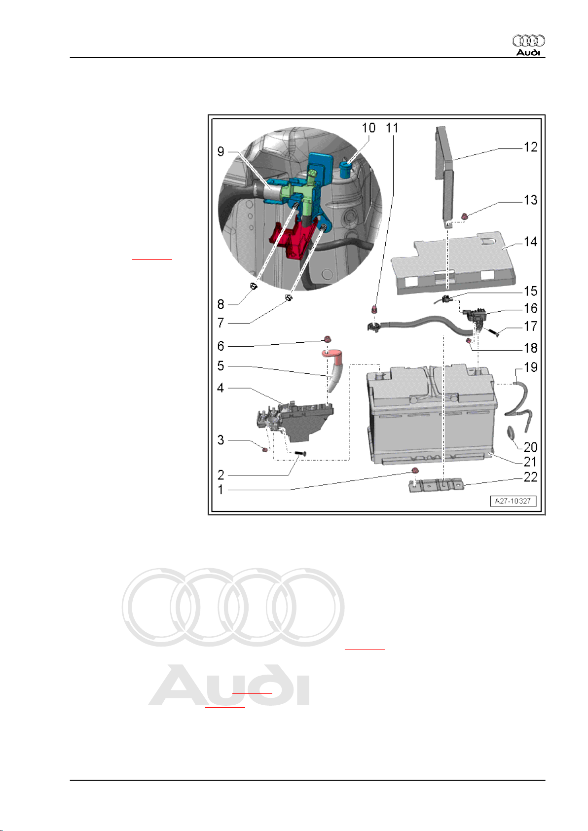
2.3 Exploded view of battery
1 - Nut
❑ 20 Nm
2 - Bolt
3 - Nut
❑ 6 Nm
4 - Main fuse box
❑ In luggage compart‐
ment (rear right) at bat‐
tery
❑ Disconnecting and con‐
necting ⇒ page 4
5 - Positive cable
❑ To engine
6 - Nut
❑ 15 Nm
7 - Nut
❑ 5.5 Nm
8 - Jump start socket -U6-
❑ Remote positive termi‐
nal of battery
9 - Nut
❑ 5.5 Nm
10 - Jump start socket (earth
stud)
❑ Remote negative termi‐
nal of battery
❑ 9 Nm
11 - Nut
❑ Tightening torque
⇒ Current flow diagrams, Electrical fault finding and Fitting locations
12 - Retainer
❑ For securing battery
13 - Nut
❑ 20 Nm
14 - Cover for negative terminal
15 - Electrical wiring
❑ For battery monitor control unit -J367❑ Observe correct sequence when connecting earth cable ⇒ page 5
Audi TT 2007 ➤
Electrical system - Edition 11.2010
16 - Earth cable with battery monitor control unit -J367-
❑ Different versions ⇒ Electronic parts catalogue
❑ Disconnecting and connecting ⇒ page 4
❑ Removing and installing ⇒ page 5
17 - Bolt
18 - Nut
❑ 6 Nm
2. Battery 3
Page 12
Protected by copyright. Copying for private or commercial purposes, in part or in whole, is not
permitted unless authorised by AUDI AG. AUDI AG does not guarantee or accept any liability
with respect to the correctness of information in this document. Copyright by AUDI AG.
Audi TT 2007 ➤
Electrical system - Edition 11.2010
19 - Hose for central gas venting system
20 - Grommet
❑ For hose for central gas venting system
21 - Battery
❑ In luggage compartment (rear right)
❑ Removing and installing ⇒ page 6
22 - Retainer plate
❑ Different versions ⇒ Electronic parts catalogue
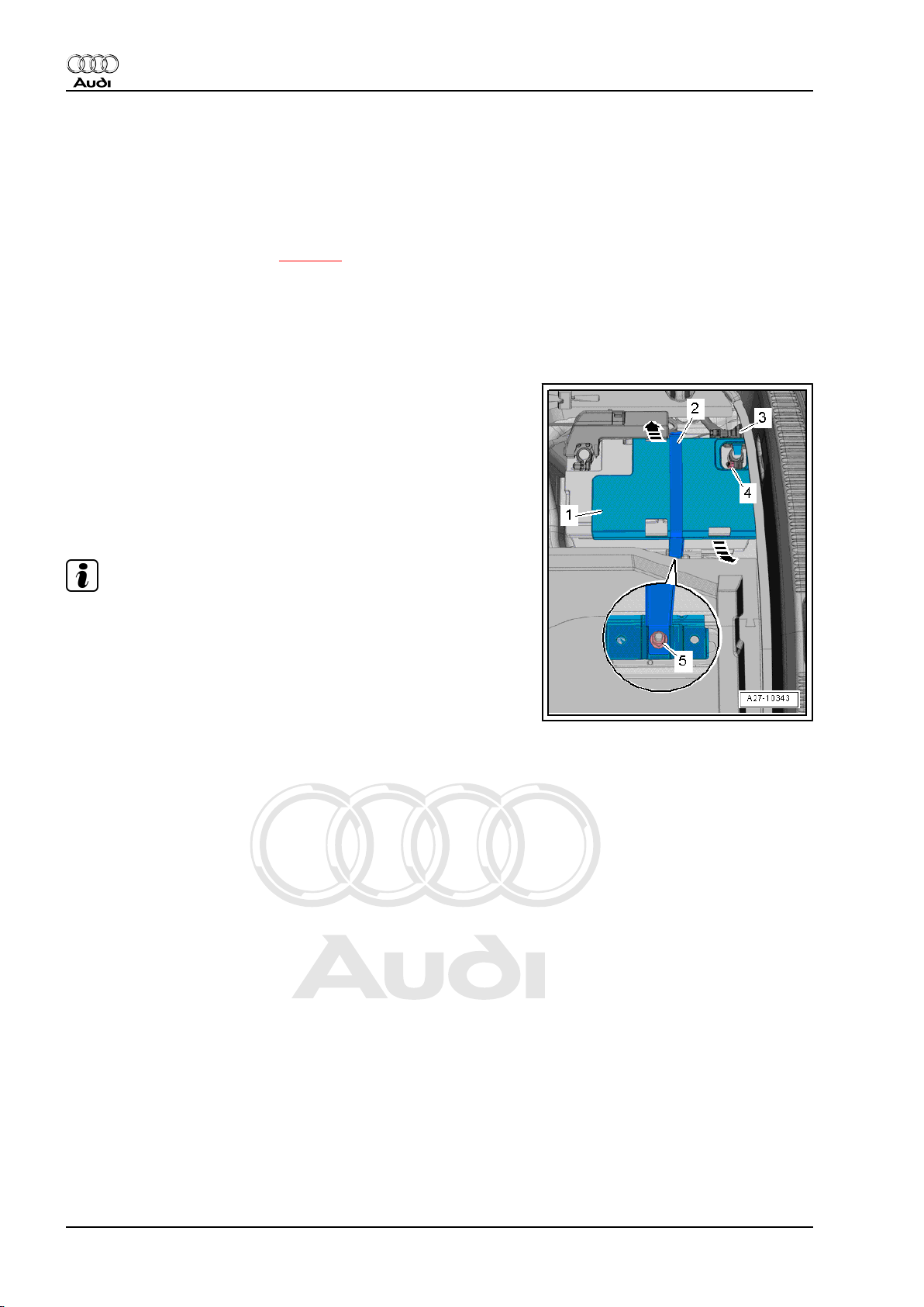
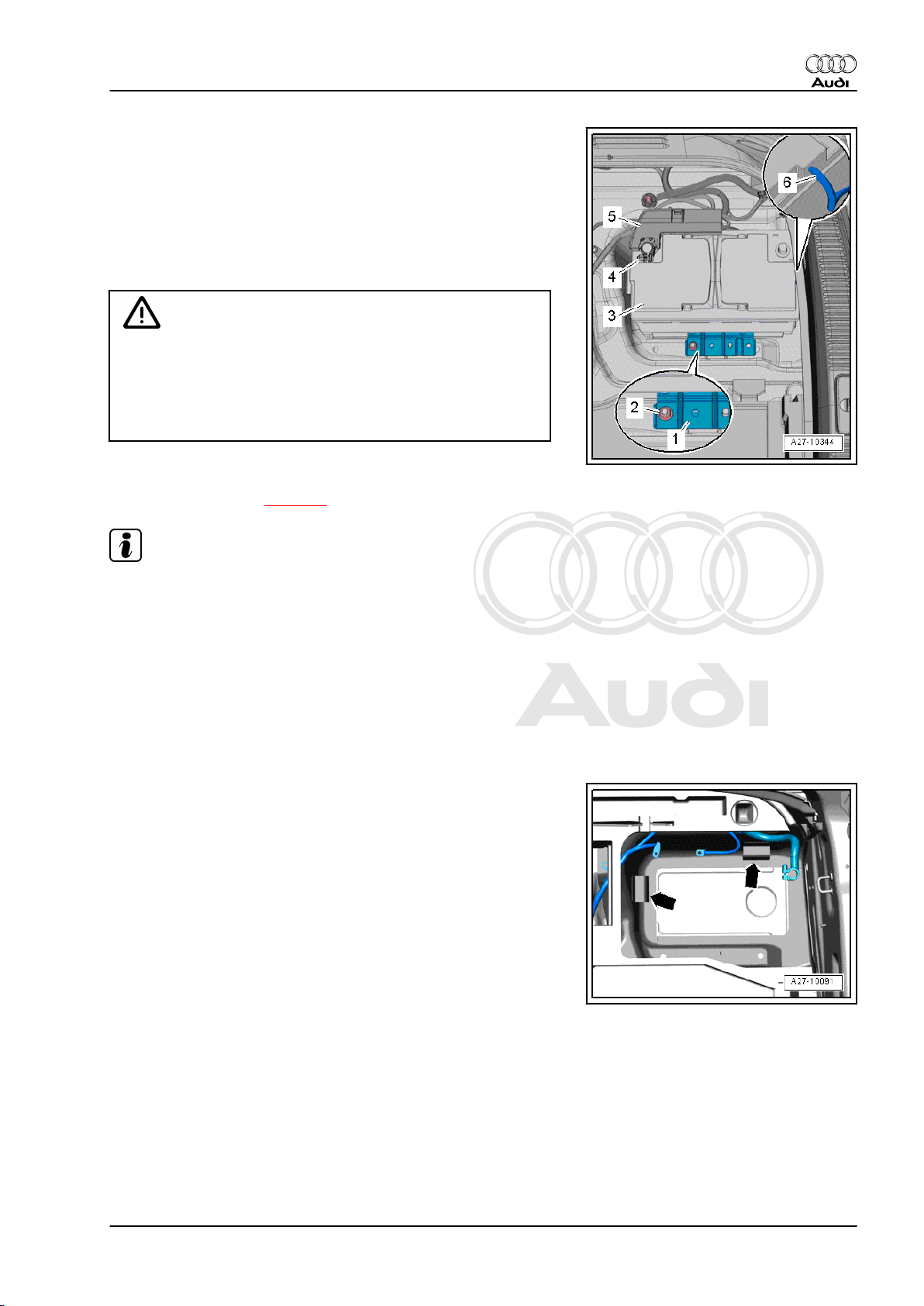
2.4 Disconnecting and connecting battery
Disconnecting
– Switch off ignition and take out ignition key.
– Remove floor covering from luggage compartment.
– If fitted, remove nut -5- and disengage retainer -2- on opposite
side.
– Release retaining clips -arrows- and remove cover -1- for neg‐
ative battery terminal.
Note
If cover for negative battery terminal is located underneath rear
cross panel trim, the rear cross panel trim must be removed ⇒
Rep. gr. 70 .
– Loosen nut -4- a few turns and disconnect battery clamp -3-
of earth cable from battery terminal.
4 Rep. gr.27 - Starter, current supply, CCS
Page 13

Protected by copyright. Copying for private or commercial purposes, in part or in whole, is not
permitted unless authorised by AUDI AG. AUDI AG does not guarantee or accept any liability
with respect to the correctness of information in this document. Copyright by AUDI AG.
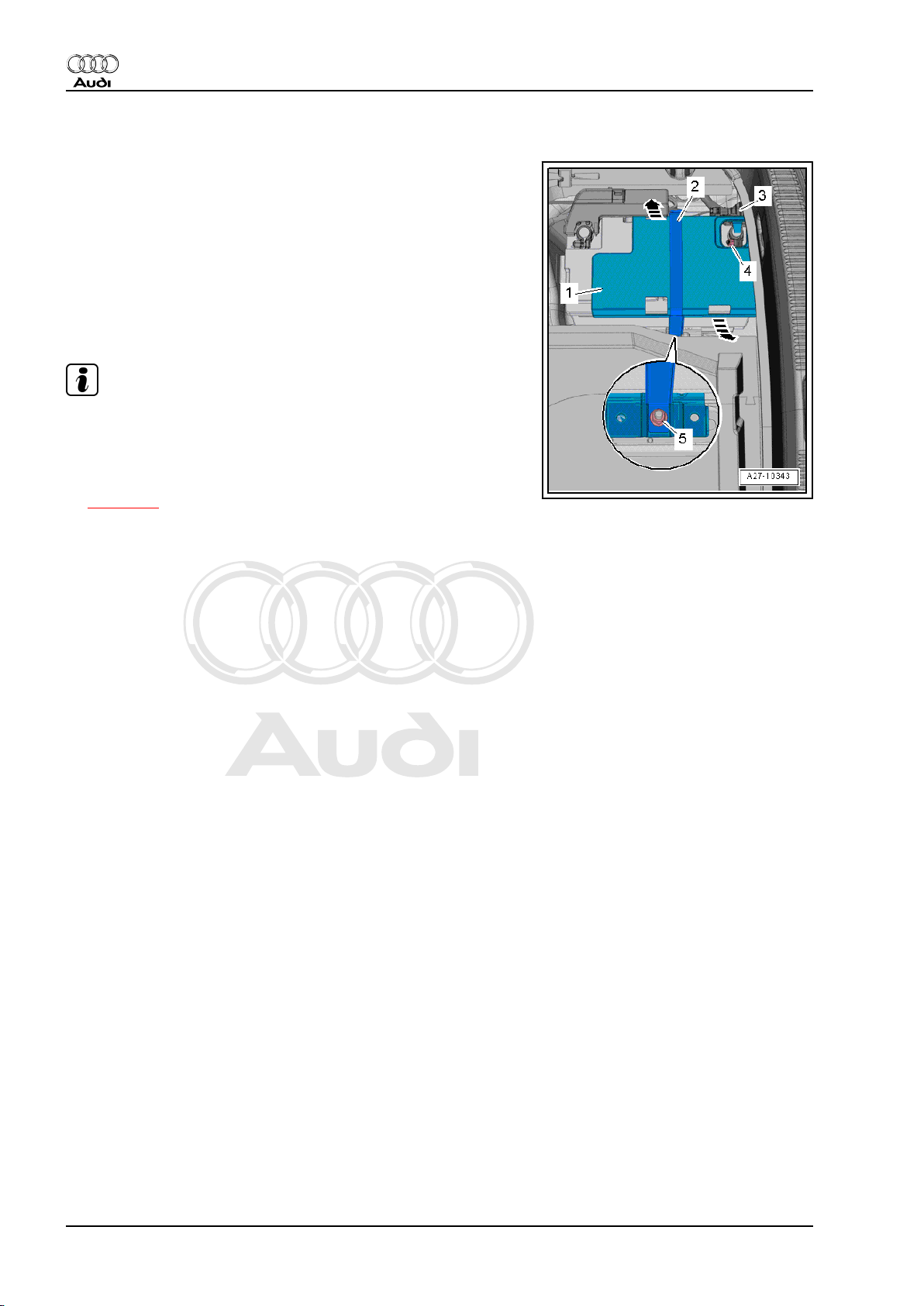
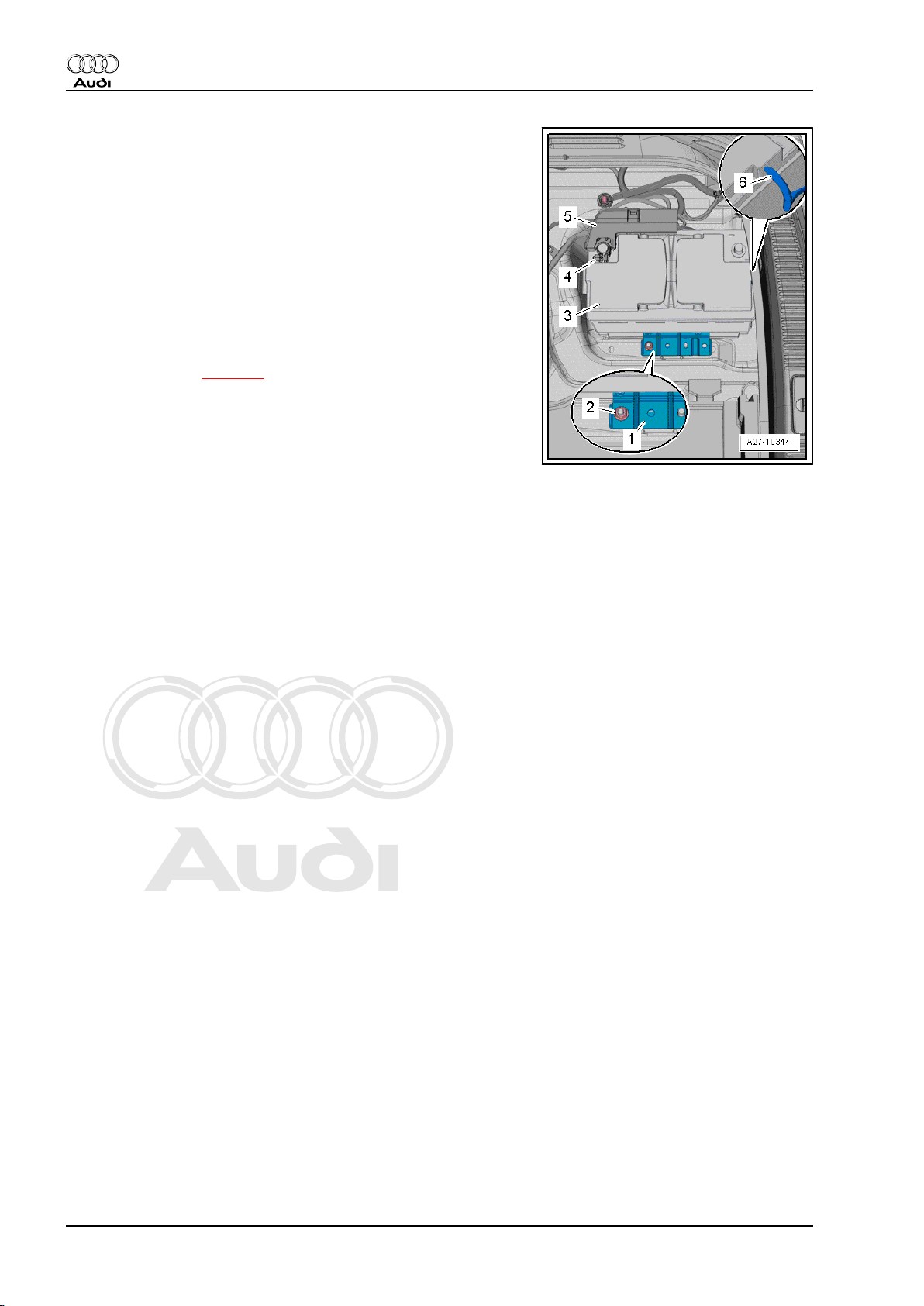
Connecting
• Tightening torque ⇒ page 3
– On vehicles with battery monitor control unit -J367- , unplug
electrical connector -2- at battery monitor control unit -J367-
-item 3-.
– When connecting battery, attach battery clamp of earth cable
to negative battery terminal „–“ by hand and tighten nut.
– Reconnect connector at battery monitor control unit -J367- .
The following measures are required after re-connecting the bat‐
tery:
♦ Activate automatic open/close function of electric window reg‐
ulators - see ⇒ Owner's Manual .
♦ Synchronise spare key and additional key to ensure correct
remote control operation. To do so, insert key in ignition lock,
switch on the ignition and then off again, then remove the key.
♦ Interrogate event memories of all control units and erase „Low
voltage“ entry ⇒ Vehicle diagnostic, testing and information
system VAS 5051.
Audi TT 2007 ➤
Electrical system - Edition 11.2010
Note
After reconnecting the voltage supply, it is possible that the ESP
warning lamp will not go out until the vehicle has been driven
several metres.
2.5 Removing and installing earth cable with battery monitor control unit -J367-
Removing
– Disconnect battery ⇒ page 4 .
– Remove foam insert (right-side) for vehicle tool kit.
– If fitted, remove spare wheel well lining ⇒ Rep. gr. 70 .
– Unplug electrical connector -4-.
– If fitted, cut through cable tie -2-.
– Remove nut -1- and detach earth cable -3- with battery monitor
control unit -J367- -item 5-.
Installing
• Tightening torques ⇒ page 3
Installation is carried out in the reverse order; note the following:
– Install foam insert (right-side) for vehicle tool kit.
– Connect battery ⇒ page 5 .
2. Battery 5
Page 14
Protected by copyright. Copying for private or commercial purposes, in part or in whole, is not
permitted unless authorised by AUDI AG. AUDI AG does not guarantee or accept any liability
with respect to the correctness of information in this document. Copyright by AUDI AG.
Audi TT 2007 ➤
Electrical system - Edition 11.2010
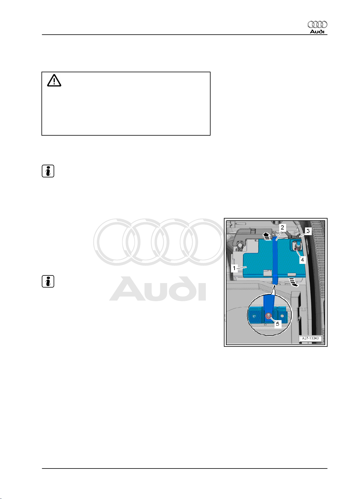
2.6 Removing and installing battery
Removing
– Switch off ignition and take out ignition key.
– Remove floor covering from luggage compartment.
– Remove foam insert (right-side) for vehicle tool kit.
– If fitted, remove nut -5- and disengage retainer -2- on opposite
side.
– Release retaining clips -arrows- and remove cover -1- for neg‐
ative battery terminal.
Note
If cover for negative battery terminal is located underneath rear
cross panel trim, the rear cross panel trim must be removed ⇒
Rep. gr. 70 .
– Connect battery charger to provide back-up power supply
⇒ page 10 .
– Loosen nut -4- a few turns and disconnect battery clamp -3-
of earth cable from battery terminal.
6 Rep. gr.27 - Starter, current supply, CCS
Page 15
Protected by copyright. Copying for private or commercial purposes, in part or in whole, is not
permitted unless authorised by AUDI AG. AUDI AG does not guarantee or accept any liability
with respect to the correctness of information in this document. Copyright by AUDI AG.
– Loosen nut -4- several turns and disconnect battery clamp
-5- of positive cable together with main fuse box from positive
battery terminal.
– Unscrew nut -2- on battery retainer plate -1-.
– Pull battery -3- slightly out of battery retainer.
– Pull off hose -6- for central gas venting system.
– Lift battery out of luggage compartment (right-side).
WARNING
Observe environmental requirements.
♦ When disposing of used batteries, always observe the re‐
quired disposal procedures for batteries and sulphuric
acid ⇒ Electrical system; General information; Rep. gr.
27 .
Installing
• Tightening torques ⇒ page 3
Audi TT 2007 ➤
Electrical system - Edition 11.2010
Note
♦
Only install maintenance-free batteries with the specifications
„TL82506“ (from December 1997 onwards) and
„VW75073“ (from August 2001 onwards).
♦
If a leakproof, deep-cycle VRLA or AGM battery was fitted as
original equipment, this type of battery must also be installed
as a replacement.
♦
Batteries from the Audi parts range feature a base strip adapt‐
er for matching to different retainer flanges. The battery oper‐
ating instructions give details of when and how to use the base
strip adapter.
– Insert battery in battery retainer; the battery base strip must
engage in the retainer flanges of the battery retainer
-arrows-.
• It should no longer be possible to move the battery.
2. Battery 7
Page 16
Protected by copyright. Copying for private or commercial purposes, in part or in whole, is not
permitted unless authorised by AUDI AG. AUDI AG does not guarantee or accept any liability
with respect to the correctness of information in this document. Copyright by AUDI AG.
Audi TT 2007 ➤
Electrical system - Edition 11.2010
– Connect hose -6- for central gas venting system. Observe
notes in ⇒ Electrical system; General information; Rep. gr.
27 .
– Place battery retainer plate -1- in position.
• Lug on battery retainer plate must engage in recess on battery
base strip.
– Tighten nut -2- for battery retainer plate.
Connect up battery -3- in the following sequence with ignition and
electrical equipment switched off:
– First connect battery clamp -5- of positive cable by hand to
positive battery terminal „+“ and tighten nut -4-.
– Connect battery ⇒ page 5 .
– Install foam insert (right-side) for vehicle tool kit.
2.7 Checking battery
The following descriptions are given in ⇒ Electrical system; Gen‐
eral information; Rep. gr. 27 :
♦ Checking battery using battery tester with printer -VAS 5097A-
♦ Measuring no-load voltage - vehicles without battery monitor
control unit -J367- or energy management control unit -J644-
♦ Checking battery by measuring current draw
♦ Checking battery - vehicles with battery monitor control unit -
J367- or energy management control unit -J644-
♦ Measuring no-load voltage - vehicles with battery monitor con‐
trol unit -J367- or energy management control unit -J644-
♦ Checking battery by measuring current draw - vehicles with
battery monitor control unit -J367- or energy management
control unit -J644-
♦ Measuring no-load voltage - vehicles with battery monitor con‐
trol unit -J367- or energy management control unit -J644„transport mode not active“
♦ Measuring no-load voltage - vehicles with battery monitor con‐
trol unit -J367- or energy management control unit -J644„transport mode active“
2.8 Charging battery
The following descriptions are given in ⇒ Electrical system; Gen‐
eral information; Rep. gr. 27 :
♦ Charging battery with battery charger -VAS 5095A- , -VAS
5900- , -VAS 5903- , -VAS 5904- or -VAS 5906-
♦ Totally discharged battery
♦ Rapid-charging battery - vehicles without battery monitor con‐
trol unit -J367- or energy management control unit -J644-
♦ Back-up power supply of battery via battery charger -VAS
5095A- , -VAS 5900- , -VAS 5903- , -VAS 5904- or -VAS 5906-
♦ Maintaining battery charge with solar panel -VAS 6102 A-
8 Rep. gr.27 - Starter, current supply, CCS
Page 17
Protected by copyright. Copying for private or commercial purposes, in part or in whole, is not
permitted unless authorised by AUDI AG. AUDI AG does not guarantee or accept any liability
with respect to the correctness of information in this document. Copyright by AUDI AG.
2.9 Preparations before charging battery
Procedure
WARNING
Risk of explosion due to a discharged battery with „magic eye“.
♦ The battery must NOT be checked or charged if the indi‐
cator of the „magic eye“ is colourless or yellow. Do NOT
boost start the vehicle. There is a risk of explosion when
checking or charging the battery or boost starting the ve‐
hicle. The battery must be renewed.
Before connecting battery charger, it is necessary to perform the
following steps:
Note
The battery clamps should normally be disconnected from the
battery before charging.
Audi TT 2007 ➤
Electrical system - Edition 11.2010
– Switch off ignition and all electrical equipment; then take out
ignition key.
Vehicles without positive terminal in engine compartment:
– Remove floor covering from luggage compartment.
– If fitted, remove nut -5- and disengage retainer -2- on opposite
side.
– Release retaining clips -arrows- and remove cover -1- for neg‐
ative battery terminal.
Note
If cover for negative battery terminal is located underneath rear
cross panel trim, the rear cross panel trim must be removed ⇒
Rep. gr. 70 .
– Loosen nut -4- a few turns and disconnect battery clamp -3-
of earth cable from battery terminal.
2. Battery 9
Page 18
Protected by copyright. Copying for private or commercial purposes, in part or in whole, is not
permitted unless authorised by AUDI AG. AUDI AG does not guarantee or accept any liability
with respect to the correctness of information in this document. Copyright by AUDI AG.
Audi TT 2007 ➤
Electrical system - Edition 11.2010
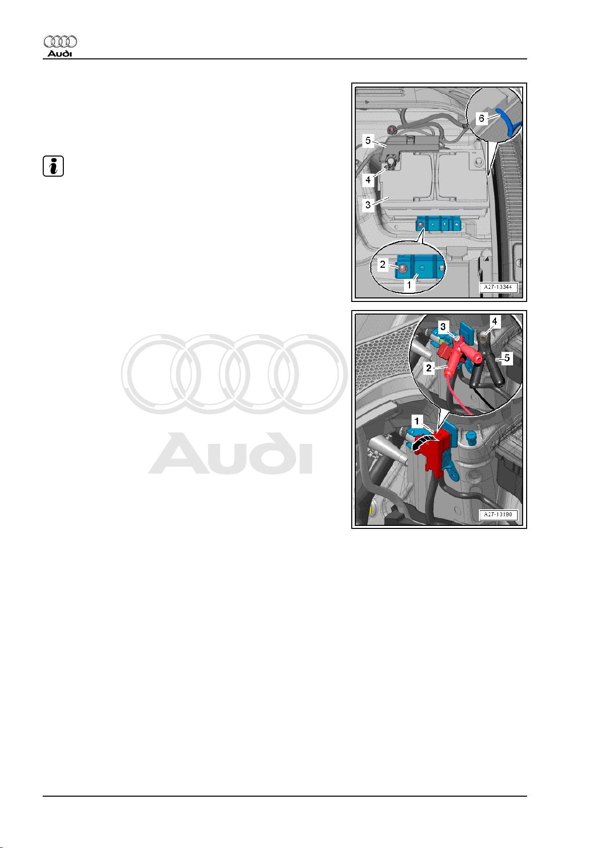
– Loosen nut -4- several turns and disconnect battery clamp
-5- of positive cable together with main fuse box from positive
battery terminal.
– Connect red clamp „+“ of battery charger to positive terminal
of battery and black clamp „–“ to negative terminal of battery.
Note
Disregard -items 1, 2, 3, 6-.
Vehicles with positive terminal in engine compartment:
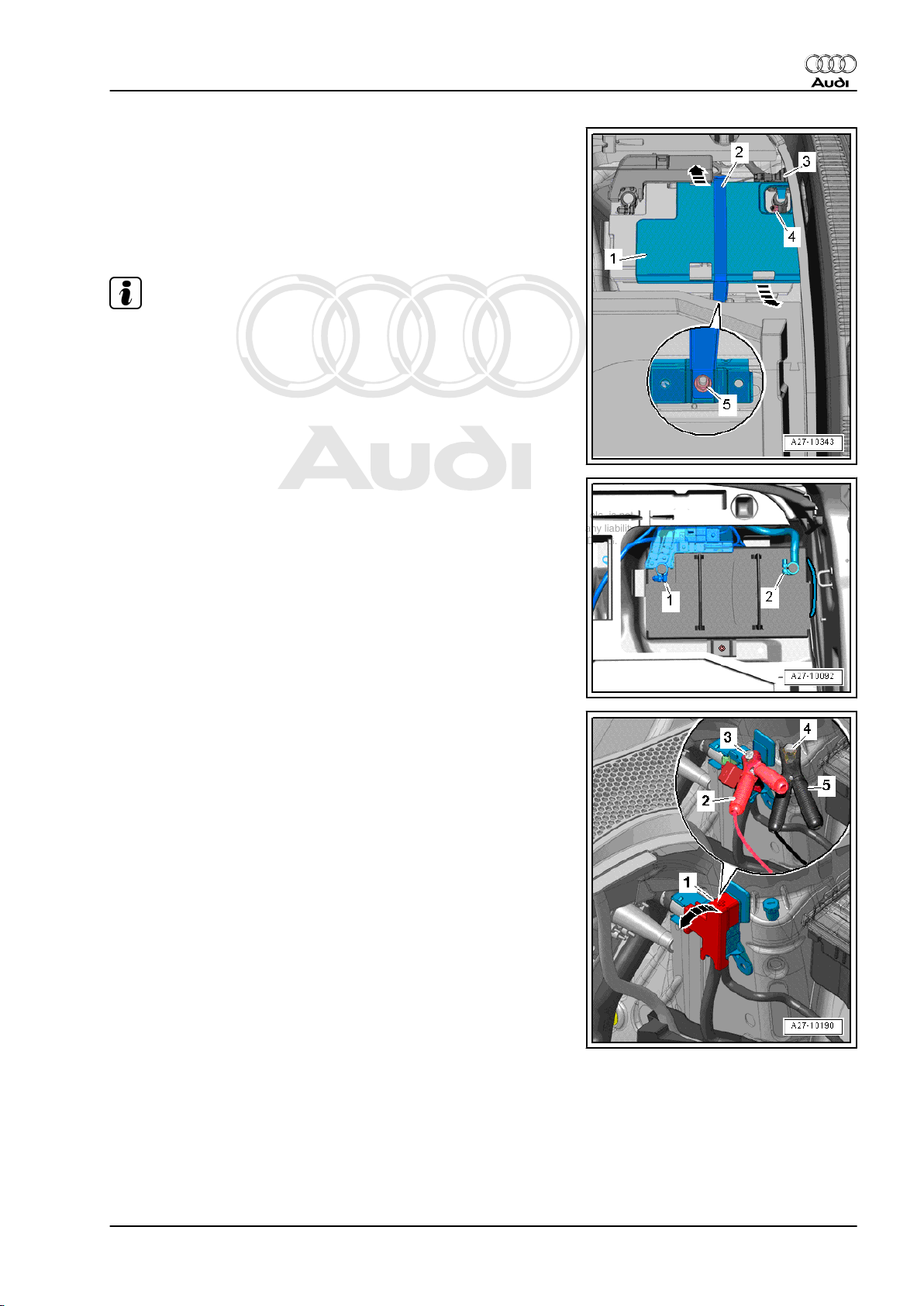
– Open cover -1- over positive battery terminal -arrow-.
– Connect red clamp „+“ -item 2- of battery charger to remote
positive terminal -3- and black clamp „–“ -item 5- to earth ter‐
minal -4-.
All models:
– Plug in mains connector of battery charger and switch on bat‐
tery charger ⇒ Electrical system; General information; Rep.
gr. 27 .
– Leave rear lid open during charging.
2.10 Preparations for back-up power supply
of battery
Procedure
Before connecting battery charger, it is necessary to perform the
following steps:
– Switch off ignition and all electrical equipment.
10 Rep. gr.27 - Starter, current supply, CCS
Page 19
Protected by copyright. Copying for private or commercial purposes, in part or in whole, is not
permitted unless authorised by AUDI AG. AUDI AG does not guarantee or accept any liability
with respect to the correctness of information in this document. Copyright by AUDI AG.
Vehicles without positive terminal in engine compartment:
– Remove floor covering from luggage compartment.
– If fitted, remove nut -5- and disengage retainer -2- on opposite
side.
– Release retaining clips -arrows- and remove cover -1- for neg‐
ative battery terminal.
Note
♦
If cover for negative battery terminal is located underneath
rear cross panel trim, the rear cross panel trim must be re‐
moved ⇒ Rep. gr. 70 .
♦
Disregard -items 3, 4-.
– Connect red clamp „+“ of battery charger to positive battery
clamp „+“ -item 1- and black clamp „–“ to negative battery
clamp „–“ -item 2-.
Audi TT 2007 ➤
Electrical system - Edition 11.2010
Vehicles with positive terminal in engine compartment:
– Open cover -1- over positive battery terminal -arrow-.
– Connect red clamp „+“ -item 2- of battery charger to remote
positive terminal -3- and black clamp „–“ -item 5- to earth ter‐
minal -4-.
All models:
– Plug in mains connector of battery charger and switch on bat‐
tery charger ⇒ Electrical system; General information; Rep.
gr. 27 .
2.11 Removing and installing battery isola‐
tion igniter -N253-
If battery isolation igniter -N253- is defective or has tripped, renew
battery isolation igniter -N253- ⇒ Rep. gr. 69 .
2. Battery 11
Page 20
Protected by copyright. Copying for private or commercial purposes, in part or in whole, is not
permitted unless authorised by AUDI AG. AUDI AG does not guarantee or accept any liability
with respect to the correctness of information in this document. Copyright by AUDI AG.
Audi TT 2007 ➤
Electrical system - Edition 11.2010
3 Removing and installing alternator
Observe notes on contact corrosion ⇒ page 1 .
3.1 Exploded view of alternator
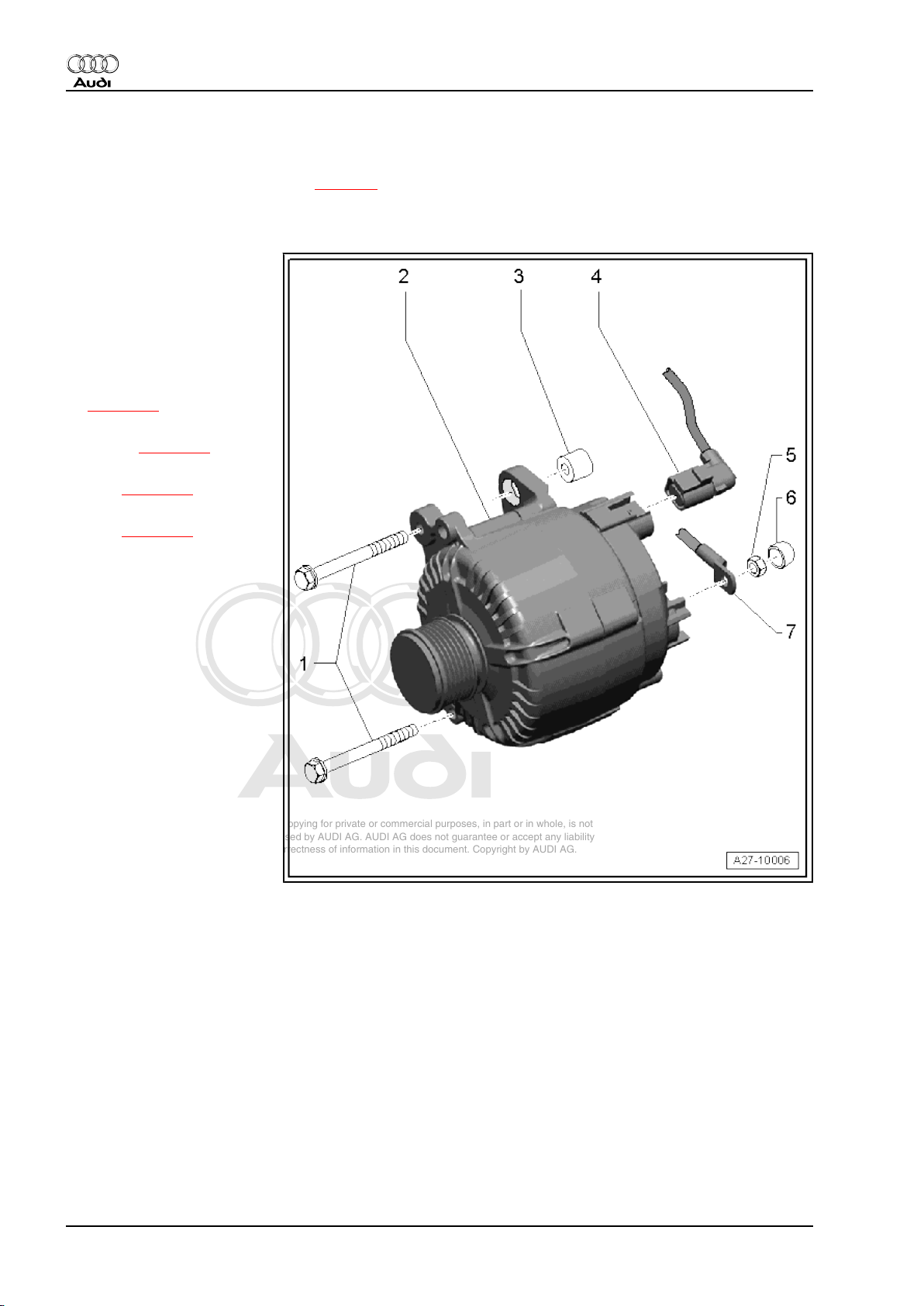
1 - Bolt
❑ 23 Nm
2 - Alternator
❑ Removing and instal‐
ling:
♦ Audi TT and TTS with
2.0 ltr. TFSI engine
⇒ page 12
♦ Audi TTRS with 2.5 ltr. TFSI
engine ⇒ page 14
♦ Audi TT with 3.2 ltr. MPI en‐
gine ⇒ page 16
♦ Audi TT with 2.0 ltr. TDI en‐
gine ⇒ page 19
3 - Sliding bush
❑ Ensure that bushes
slide freely, as the
clamping pressure of a
stiff bush will be insuffi‐
cient even when the cor‐
rect tightening torque is
applied
4 - Electrical connector
5 - Nut
❑ 15 Nm
6 - Cap
7 - Terminal 30/B+
3.2 Audi TT and TTS with 2.0 ltr. TFSI en‐
gine
Special tools and workshop equipment required
12 Rep. gr.27 - Starter, current supply, CCS
Page 21
Protected by copyright. Copying for private or commercial purposes, in part or in whole, is not
permitted unless authorised by AUDI AG. AUDI AG does not guarantee or accept any liability
with respect to the correctness of information in this document. Copyright by AUDI AG.
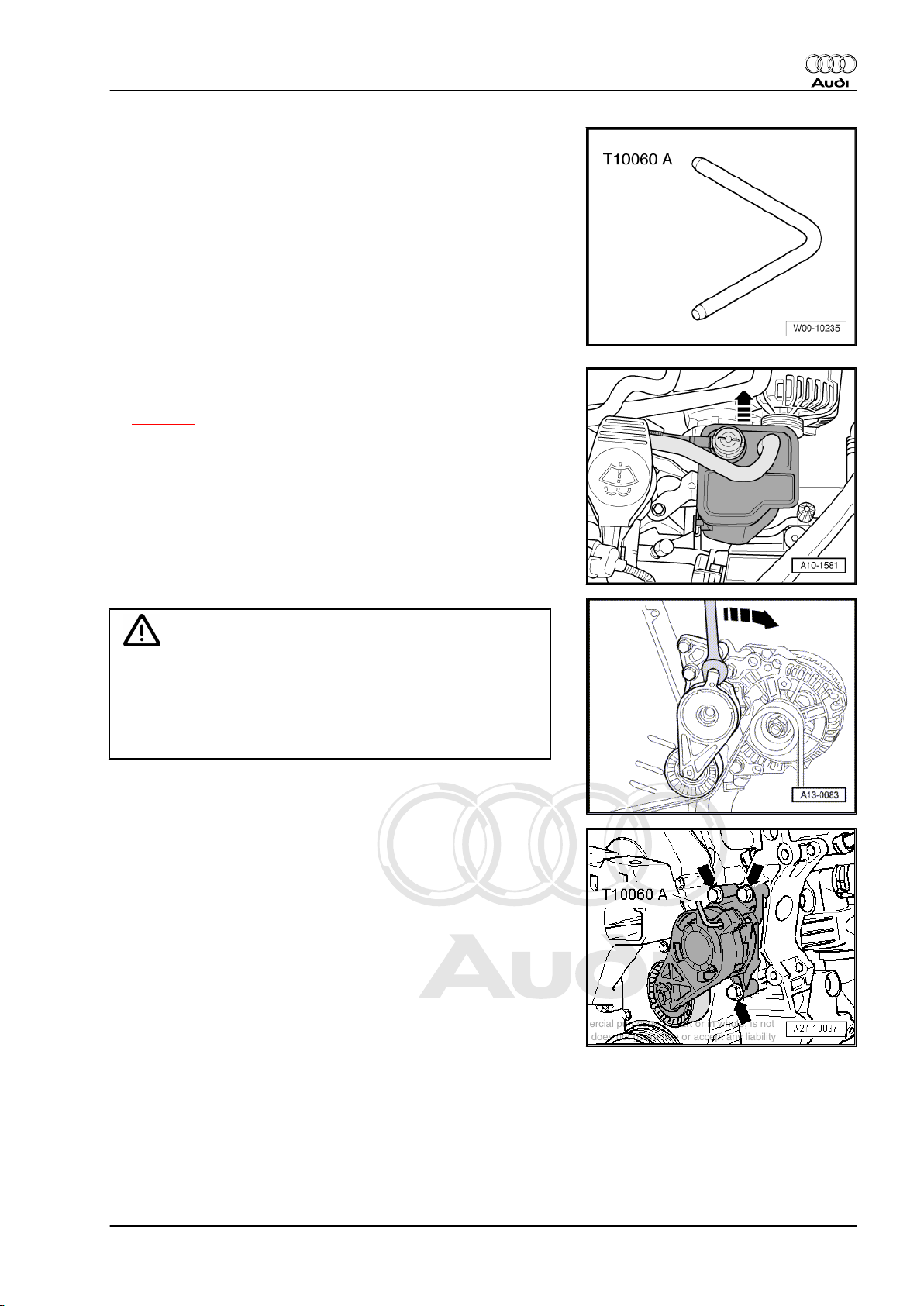
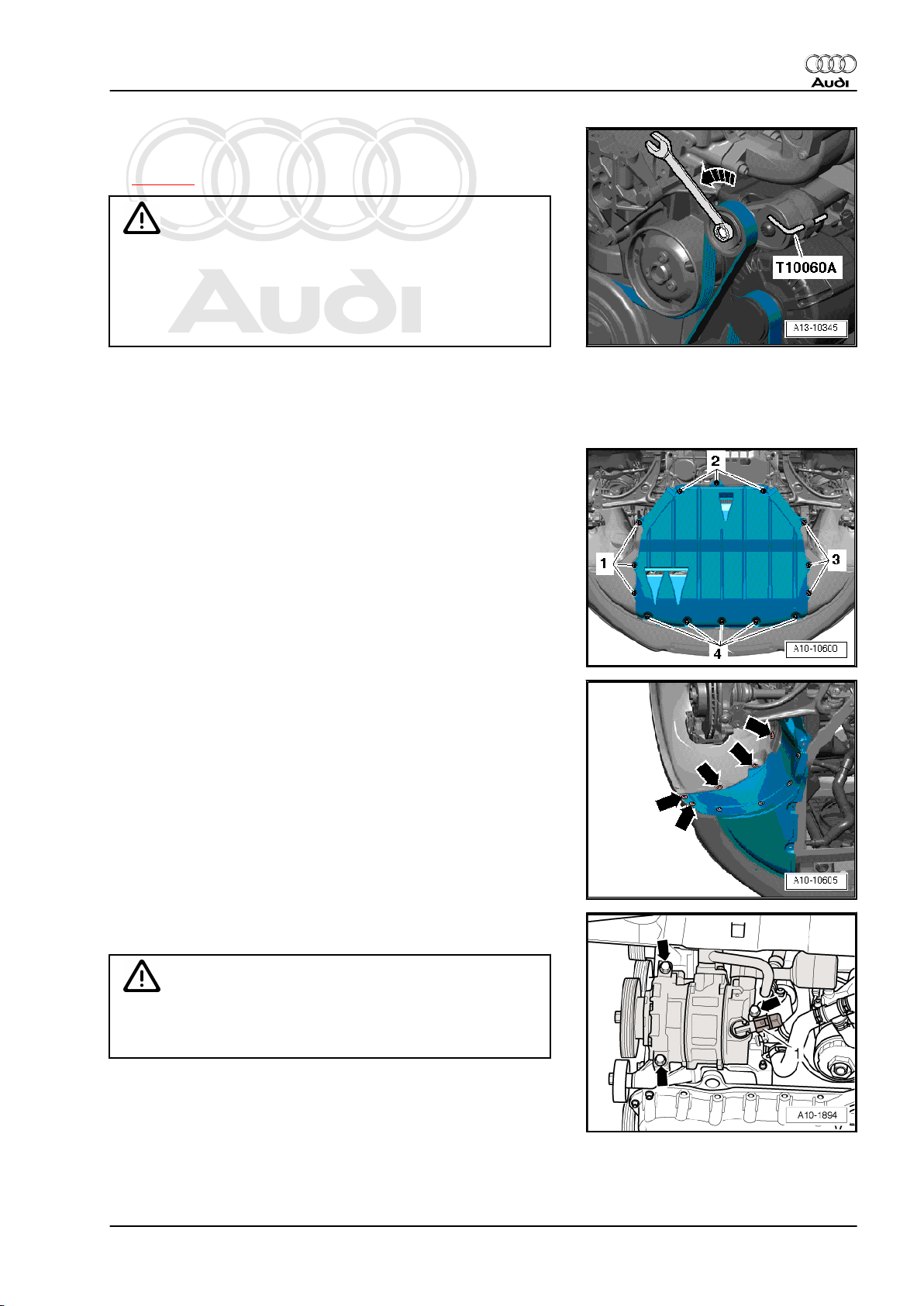
♦ Locking pin -T10060 A-
Removing
– With ignition switched off, disconnect earth cable at battery
⇒ page 4 .
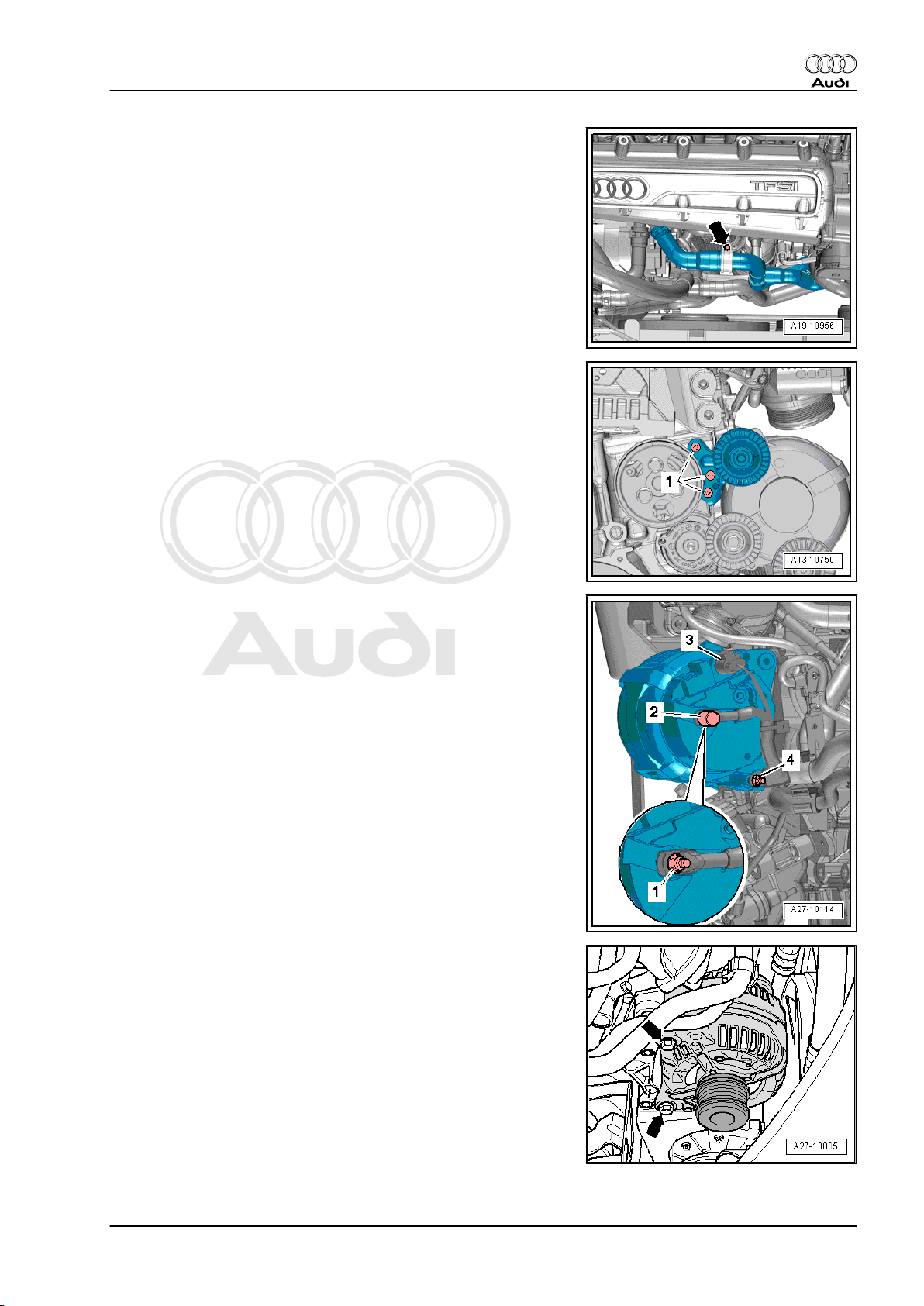
– Lift activated charcoal filter out of bracket -arrow- and place it
aside with hoses still attached.
Audi TT 2007 ➤
Electrical system - Edition 11.2010
Caution
Risk of breakage if the poly V-belt runs in the opposite direction
when refitted.
♦ Before removing, mark direction of operation of poly V-belt
with chalk or felt-tipped pen in preparation for re-installa‐
tion.
– To slacken poly V-belt, turn tensioner in direction of -arrow-.
– Lock the poly V-belt tensioner using the locking pin -T10060
A- .
– Take off poly V-belt.
– Remove poly V-belt tensioner -arrows-.
3. Removing and installing alternator 13
Page 22
Protected by copyright. Copying for private or commercial purposes, in part or in whole, is not
permitted unless authorised by AUDI AG. AUDI AG does not guarantee or accept any liability
with respect to the correctness of information in this document. Copyright by AUDI AG.
Audi TT 2007 ➤
Electrical system - Edition 11.2010
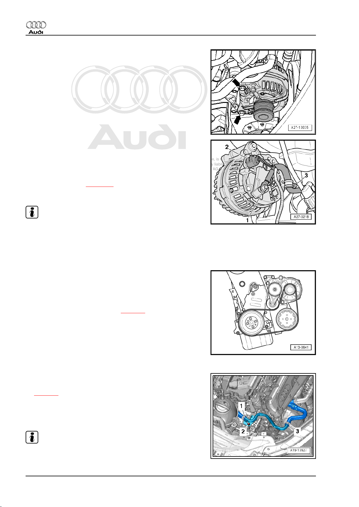
– Unscrew bolts -arrows- for alternator approx. 6 turns.
– Tap carefully on bolt heads with a hammer to release sliding
bushes securing alternator.
– Remove bolts.
– Detach alternator from bracket for ancillaries.
– Swivel alternator towards right side of vehicle with electrical
wiring still connected.
– Unplug electrical connector -2-.
– Unscrew electrical wiring -1- and clamp -3- from alternator.
– Lift out alternator.
Installing
• Tightening torques ⇒ page 12
Installation is carried out in the reverse order; note the following:
Note
You must ensure that the bushes slide freely, as the clamping
pressure of a stiff bush will be insufficient even when the correct
tightening torque is applied.
– To facilitate positioning of alternator, drive back sliding bushes
for securing bolts slightly.
– Fit poly V-belt on pulleys of crankshaft, air conditioner com‐
pressor and alternator.
– Install tensioner for poly V-belt ⇒ Rep. gr. 13 .
– Check correct positioning of poly V-belt.
– Connect battery. Steps required ⇒ page 5 .
– Start engine and check that belt runs properly.
3.3 Audi TT RS with 2.5 ltr. TFSI engine
Removing
– With ignition switched off, disconnect earth cable at battery
⇒ page 4 .
– Remove poly V-belt tensioner for alternator and coolant pump
⇒ Rep. gr. 13 .
– Remove bolt -2- for coolant pipe (right-side).
Note
Disregard -items 1, 3-.
14 Rep. gr.27 - Starter, current supply, CCS
Page 23
Protected by copyright. Copying for private or commercial purposes, in part or in whole, is not
permitted unless authorised by AUDI AG. AUDI AG does not guarantee or accept any liability
with respect to the correctness of information in this document. Copyright by AUDI AG.
– Remove bolt -arrow- at retaining clip.
– Unscrew bolts -1- and detach idler roller.
Audi TT 2007 ➤
Electrical system - Edition 11.2010
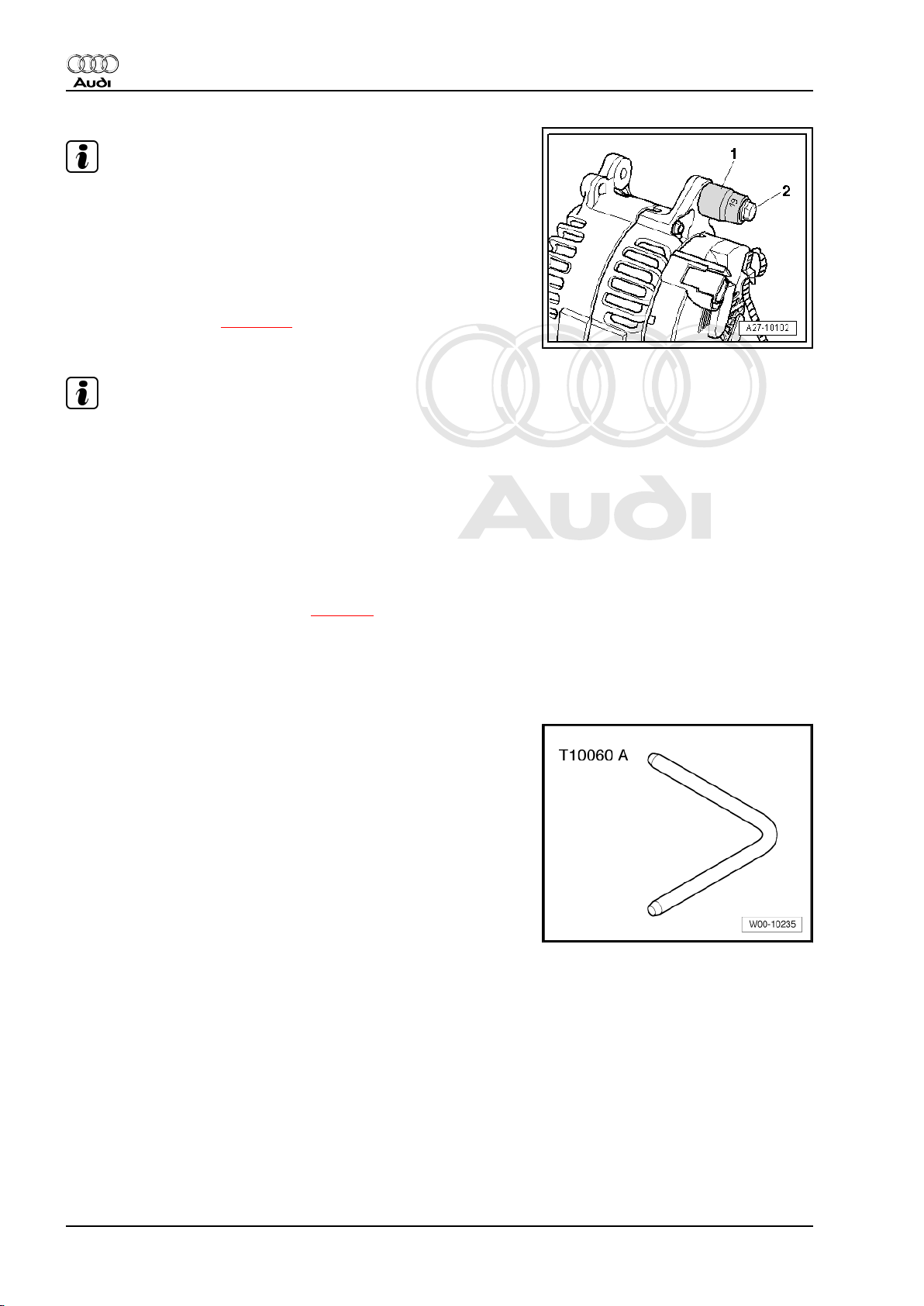
– Unplug electrical connector -3-.
– Pry off protective cap -2- and unscrew nut -1- for terminal 30/
B+.
– Unscrew nut -4- and pull off clamp.
– Remove bolts -arrows-.
– Lift out alternator.
3. Removing and installing alternator 15
Page 24
Protected by copyright. Copying for private or commercial purposes, in part or in whole, is not
permitted unless authorised by AUDI AG. AUDI AG does not guarantee or accept any liability
with respect to the correctness of information in this document. Copyright by AUDI AG.
Audi TT 2007 ➤
Electrical system - Edition 11.2010
Note
♦
If alternator sticks in bracket, apply a 1/2 inch socket (19 mm)
-item 1- at sliding bush.
♦
Screw a bolt (M8x45) into sliding bush and then pull bush out
of alternator by screwing in bolt.
Installing
• Tightening torques ⇒ page 12
Installation is carried out in the reverse order; note the following:
Note
You must ensure that the bushes slide freely, as the clamping
pressure of a stiff bush will be insufficient even when the correct
tightening torque is applied.
– To facilitate positioning of alternator, drive back sliding bushes
for securing bolts slightly.
– Install poly V-belt tensioner for alternator and coolant pump ⇒
Rep. gr. 13 .
– Install coolant pipe (right-side) ⇒ Rep. gr. 19 .
– Connect battery. Steps required ⇒ page 5 .
– Start engine and check that belt runs properly.
3.4 Audi TT with 3.2 ltr. MPI engine
Special tools and workshop equipment required
♦ Locking pin -T10060 A-
16 Rep. gr.27 - Starter, current supply, CCS
Page 25
Protected by copyright. Copying for private or commercial purposes, in part or in whole, is not
permitted unless authorised by AUDI AG. AUDI AG does not guarantee or accept any liability
with respect to the correctness of information in this document. Copyright by AUDI AG.
Removing
– With ignition switched off, disconnect earth cable at battery
⇒ page 4 .
Caution
Risk of breakage if the poly V-belt runs in the opposite direction
when refitted.
♦ Before removing, mark direction of operation of poly V-belt
with chalk or felt-tipped pen in preparation for re-installa‐
tion.
– Slacken poly V-belt by turning tensioner in direction of
-arrow- and lock tensioner using locking pin -T10060 A- .
– Take off poly V-belt.
– Remove front wheel (right-side).
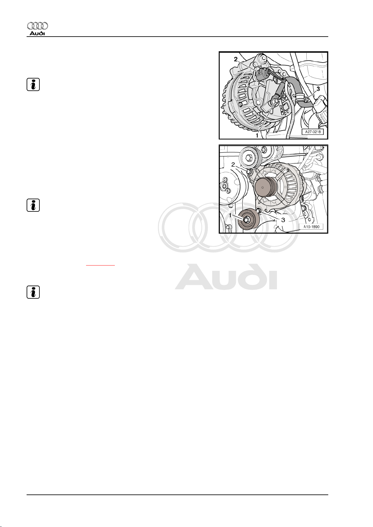
– Release fasteners -1 … 4- and remove noise insulation (cen‐
tre).
Audi TT 2007 ➤
Electrical system - Edition 11.2010
– Remove noise insulation (right-side) -arrows-.
– Unplug electrical connector -1- for magnetic clutch at air con‐
ditioner compressor and move wiring clear.
WARNING
Risk of injury due to refrigerant.
♦ Do not open refrigerant circuit of air conditioner.
– Remove bolts -arrows- for air conditioner compressor.
– Tie up air conditioner compressor to frame for noise insulation
(front) with refrigerant hoses connected.
3. Removing and installing alternator 17
Page 26
Protected by copyright. Copying for private or commercial purposes, in part or in whole, is not
permitted unless authorised by AUDI AG. AUDI AG does not guarantee or accept any liability
with respect to the correctness of information in this document. Copyright by AUDI AG.
Audi TT 2007 ➤
Electrical system - Edition 11.2010
– Detach cap (if fitted) and unscrew wiring -1- at alternator.
– Unplug electrical connector -2-.
Note
Disregard -item 3-.
– Remove upper idler roller -1-.
– Unscrew bolts -2 and 3- for alternator approx. 6 turns.
– Tap carefully on bolt heads with a hammer to release bushes
securing alternator.
– Remove bolts.
Note
To remove alternator from engine compartment, turn alternator
so that pulley is pointing upwards.
– Remove alternator from below.
Installing
• Tightening torque ⇒ page 12
Installation is carried out in the reverse order; note the following:
Note
♦
You must ensure that the bushes slide freely, as the clamping
pressure of a stiff bush will be insufficient even when the cor‐
rect tightening torque is applied.
♦
Before fitting poly V-belt, make sure all ancillary units (alter‐
nator, air conditioner compressor) are firmly secured.
– To facilitate positioning of alternator, drive back sliding bushes
for securing bolts slightly.
– Install air conditioner compressor ⇒ Rep. gr. 87 .
18 Rep. gr.27 - Starter, current supply, CCS
Page 27
Protected by copyright. Copying for private or commercial purposes, in part or in whole, is not
permitted unless authorised by AUDI AG. AUDI AG does not guarantee or accept any liability
with respect to the correctness of information in this document. Copyright by AUDI AG.
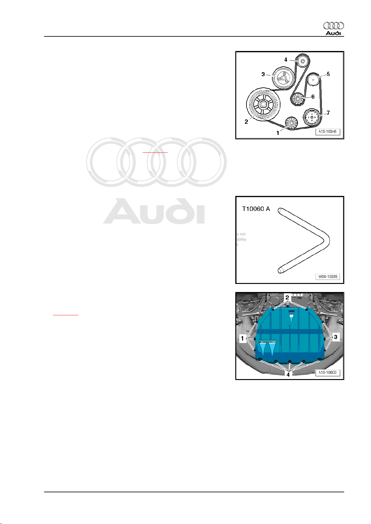
– Fit poly V-belt onto:
1 - Idler roller
2 - Vibration damper
3 - Coolant pump
4 - Tensioning roller
5 - Alternator
6 - Idler roller
7 - Air conditioner compressor
– Check correct positioning of poly V-belt.
– Connect battery. Steps required ⇒ page 5 .
– Start engine and check that belt runs properly.
3.5 Audi TT with 2.0 ltr. TDI engine
Special tools and workshop equipment required
♦ Locking pin -T10060 A-
Audi TT 2007 ➤
Electrical system - Edition 11.2010
Removing
– With ignition switched off, disconnect earth cable at battery
⇒ page 4 .
– Release fasteners -1 … 4- and remove noise insulation (cen‐
tre).
– Remove front right wheel housing liner ⇒ Rep. gr. 66 .
– Remove radiator cowl ⇒ Rep. gr. 19 .
3. Removing and installing alternator 19
Page 28
Protected by copyright. Copying for private or commercial purposes, in part or in whole, is not
permitted unless authorised by AUDI AG. AUDI AG does not guarantee or accept any liability
with respect to the correctness of information in this document. Copyright by AUDI AG.
Audi TT 2007 ➤
Electrical system - Edition 11.2010
Caution
Risk of breakage if the poly V-belt runs in the opposite direction
when refitted.
♦ Before removing, mark direction of operation of poly V-belt
with chalk or felt-tipped pen in preparation for re-installa‐
tion.
– To slacken poly V-belt turn tensioner clockwise -arrow-.
– Secure tensioner with locking pin -T10060 A- .
– Take off poly V-belt.
– Unplug electrical connector -2- at air conditioner compressor
regulating valve -N280- .
Caution
Risk of damage to air conditioner compressor and refrigerant
lines/hoses.
♦ Take care to avoid straining, kinking or bending refrigerant
lines/hoses.
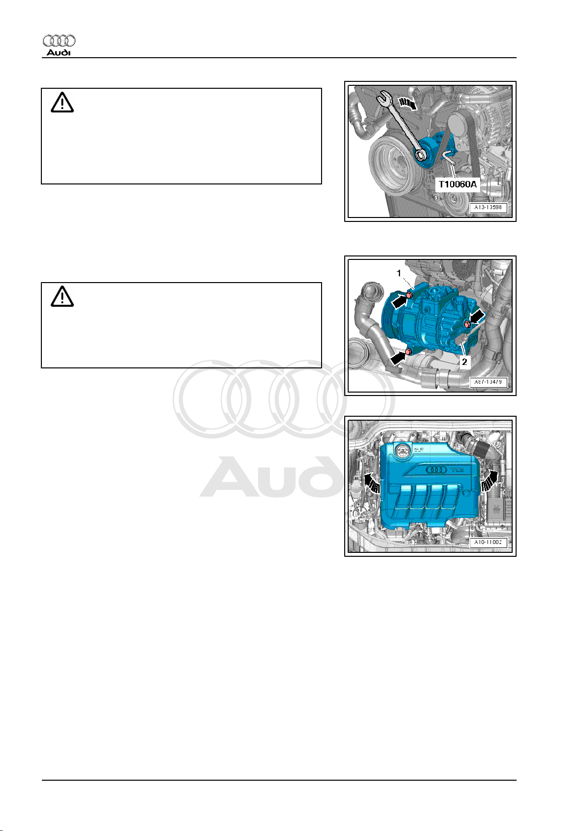
– Unscrew bolts -arrows- and detach air conditioner compressor
-1- (with refrigerant lines still connected).
Engine generation I:
– Detach engine cover panel -arrows-.
20 Rep. gr.27 - Starter, current supply, CCS
Page 29

Protected by copyright. Copying for private or commercial purposes, in part or in whole, is not
permitted unless authorised by AUDI AG. AUDI AG does not guarantee or accept any liability
with respect to the correctness of information in this document. Copyright by AUDI AG.
– Remove bolts -1- and -3-.
– Unplug electrical connector -4-.
– Unfasten clamp -5- at intake manifold flap motor -V157- and
pull off air pipe -2-.
Engine generation II:
– Detach engine cover panel -arrows-.
Audi TT 2007 ➤
Electrical system - Edition 11.2010
– Remove bolts -arrows-.
– Move clear coolant hose -3-.
– Release hose clip -2-.
– Unplug electrical connector -1- at charge pressure sender -
G31- / intake air temperature sender -G42- and detach air pipe
(right-side).
3. Removing and installing alternator 21
Page 30
Protected by copyright. Copying for private or commercial purposes, in part or in whole, is not
permitted unless authorised by AUDI AG. AUDI AG does not guarantee or accept any liability
with respect to the correctness of information in this document. Copyright by AUDI AG.
Audi TT 2007 ➤
Electrical system - Edition 11.2010
All engines (continued):
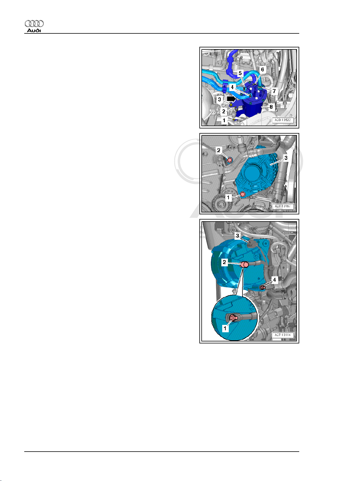
– Loosen bolt -1-.
– Remove nut -2- and bolt -3-.
– Detach hose retainer -arrow- from fuel filter and place fuel filter
-8- to one side (with fuel hoses -4 … 7-connected).
– Remove bolt -2-.
– Swivel alternator forwards and unplug electrical connector
-3-.
– Pry off protective cap -2- and unscrew nut -1- for terminal 30/
B+.
– Unscrew nut -4- and pull off clamp.
22 Rep. gr.27 - Starter, current supply, CCS
Page 31

Protected by copyright. Copying for private or commercial purposes, in part or in whole, is not
permitted unless authorised by AUDI AG. AUDI AG does not guarantee or accept any liability
with respect to the correctness of information in this document. Copyright by AUDI AG.
– Unscrew bolt -1- and take out alternator -3- downwards and to
the right; to do so, move air conditioner compressor to the left
(as seen in direction of travel).
Note
♦
If alternator sticks in bracket, screw bolts back in again down
to the last 2 turns.
♦
Tap carefully on bolt heads with flat side of hammer to release
threaded bushes of alternator mountings.
Installing
• Tightening torque ⇒ page 12
Installation is carried out in the reverse order; note the following:
– To facilitate positioning of alternator, slightly drive back bush‐
es for bolts.
Note
Audi TT 2007 ➤
Electrical system - Edition 11.2010
Stiff alternator mount bushes must be freed; otherwise the clamp‐
ing force of the bush will not be adequate even when the bolts are
tightened to the correct torque.
– Install air pipe ⇒ Rep. gr. 21 .
– Install air conditioner compressor ⇒ Rep. gr. 87 .
– Install radiator cowl ⇒ Rep. gr. 19 .
– Position poly V-belt on pulleys:
1 - Crankshaft
2 - Tensioner
3 - Alternator
4 - Air conditioner compressor
– Use ring spanner to hold tensioner and pull out locking pin -
T10060 A- .
– Release pressure from tensioner.
Note
When installing poly V-belt, make sure it is properly seated on
pulleys.
– Connect battery. Steps required ⇒ page 5 .
– Start engine and check that belt runs properly.
– Install front right wheel housing liner ⇒ Rep. gr. 66 .
– Install noise insulation ⇒ Rep. gr. 50 .
3. Removing and installing alternator 23
Page 32

Protected by copyright. Copying for private or commercial purposes, in part or in whole, is not
permitted unless authorised by AUDI AG. AUDI AG does not guarantee or accept any liability
with respect to the correctness of information in this document. Copyright by AUDI AG.
Audi TT 2007 ➤
Electrical system - Edition 11.2010
4 Checking and servicing alternator
4.1 Checking alternator
The alternator should be checked in „Guided Fault Finding“ ⇒
vehicle diagnostic tester .
– Select function or path:
Go to button
Selecting function/component
+ Body (Repair Groups 01, 27, 50 - 97)
+ Electrical system (Repair Groups 01, 27, 90 - 97)
+ 27 Starter, current supply
– Continue to follow the instructions on the display of the vehicle
+ Electrical components
C- Alternator, functional check (Repair Group 27)
diagnostic tester.
4.2 Servicing alternator
The following descriptions are given in ⇒ Electrical system; Gen‐
eral information; Rep. gr. 27 :
♦ Bosch alternator from 2001 onwards - exploded view
♦ Removing and installing voltage regulator - Bosch alternator
from 2001 onwards
♦ Bosch alternator from 2007 onwards - exploded view
♦ Removing and installing voltage regulator - Bosch alternator
from 2007 onwards
♦ Checking carbon brushes - all types of Bosch alternators from
2001 onwards
♦ Valeo alternator from 2001 onwards - exploded view
♦ Removing and installing voltage regulator - Valeo alternator
from 2001 onwards
♦ Checking carbon brushes - Valeo alternator from 2001 on‐
wards
♦ Removing and installing voltage regulator - Valeo alternator
from 2007 onwards
♦ Checking carbon brushes - Valeo alternator from 2007 on‐
wards
♦ Removing and installing poly V-belt pulley without free-wheel
♦ Removing and installing poly V-belt pulley with free-wheel
24 Rep. gr.27 - Starter, current supply, CCS
Page 33

Protected by copyright. Copying for private or commercial purposes, in part or in whole, is not
permitted unless authorised by AUDI AG. AUDI AG does not guarantee or accept any liability
with respect to the correctness of information in this document. Copyright by AUDI AG.
5 Removing and installing starter
Observe notes on contact corrosion ⇒ page 1 .
5.1 Exploded view of starter
1 - Bolt
❑ Tightening torque:
Audi TT and TTS with
manual gearbox ⇒ Rep.
gr. 34
Audi TT and TTS with di‐
rect shift gearbox: 40 Nm
2 - Earth cable
3 - Nut
❑ For earth wire
❑ 23 Nm
4 - Electrical connector
5 - Nut
❑ 15 Nm
6 - Protective sleeve
7 - Terminal B+
8 - Starter
❑ Removing and instal‐
ling:
♦ Audi TT with 2.0 ltr. TFSI
engine: Manual gearbox
⇒ page 26 ; direct shift
gearbox ⇒ page 26
♦ Audi TTS with 2.0 ltr. TFSI
engine and direct shift
gearbox ⇒ page 27
♦ Audi TTRS with 2.5 ltr. TFSI
engine and manual gear‐
box ⇒ page 28
♦ Audi TT with 3.2 ltr. MPI en‐
gine: Manual gearbox ⇒ page 29 ; direct shift gearbox ⇒ page 31
♦ Audi TT with 2.0 ltr. TDI engine and manual gearbox ⇒ page 32
9 - Nut
❑ For bracket for wiring harness
❑ 23 Nm
10 - Bracket for wiring harness
Audi TT 2007 ➤
Electrical system - Edition 11.2010
11 - Bolt
❑ Tightening torque:
Audi TT and TTS with manual gearbox ⇒ Rep. gr. 34
Audi TT with direct shift gearbox: 40 Nm
5. Removing and installing starter 25
Page 34

Protected by copyright. Copying for private or commercial purposes, in part or in whole, is not
permitted unless authorised by AUDI AG. AUDI AG does not guarantee or accept any liability
with respect to the correctness of information in this document. Copyright by AUDI AG.
Audi TT 2007 ➤
Electrical system - Edition 11.2010
5.2 Audi TT with 2.0 ltr. TFSI engine and manual gearbox
Removing
– With ignition switched off, disconnect earth cable at battery
⇒ page 4 .
– Unplug electrical connector -4-.
– Fold back protective sleeve -3- and detach B+ wire -item 5-
from solenoid switch.
– Unscrew earth cable -2-.
– Remove upper starter bolt -1-.
– Unscrew nut -3- from lower starter bolt and detach bracket
-2- for wiring harness.
– Remove lower starter bolt -1- (accessible from above) and de‐
tach starter.
Installing
• Tightening torques ⇒ page 25
Installation is carried out in the reverse order; note the following:
– Connect battery. Steps required ⇒ page 5 .
5.3 Audi TT with 2.0 ltr. TFSI engine and di‐
rect shift gearbox
Removing
Note
All cable ties which are released or cut open when removing must
be fitted in the same position when installing.
– With ignition switched off, disconnect earth cable at battery
⇒ page 4 .
26 Rep. gr.27 - Starter, current supply, CCS
Page 35

Protected by copyright. Copying for private or commercial purposes, in part or in whole, is not
permitted unless authorised by AUDI AG. AUDI AG does not guarantee or accept any liability
with respect to the correctness of information in this document. Copyright by AUDI AG.
– Remove cable tie -arrow- for protective sleeve.
– Unplug electrical connector -2-.
– Fold back protective sleeve -1- and detach B+ wire from sol‐
enoid switch.
– Unscrew earth cable -3-.
– Remove lower starter bolt (accessible from above).
– Remove upper starter bolt and detach starter.
Note
Disregard -item 4-.
Installing
• Tightening torques ⇒ page 25
Installation is carried out in the reverse order; note the following:
– Connect battery. Steps required ⇒ page 5 .
Audi TT 2007 ➤
Electrical system - Edition 11.2010
5.4 Audi TTS with 2.0 ltr. TFSI engine and direct shift gearbox
Removing
– With ignition switched off, disconnect earth cable at battery
⇒ page 4 .
– Unplug electrical connector -2- for air mass meter -G70- .
– Remove air hose -1-.
– Unbolt air cleaner (top section) -3- and take out air filter ele‐
ment.
– Remove bolts -arrows- and detach air duct.
5. Removing and installing starter 27
Page 36

Protected by copyright. Copying for private or commercial purposes, in part or in whole, is not
permitted unless authorised by AUDI AG. AUDI AG does not guarantee or accept any liability
with respect to the correctness of information in this document. Copyright by AUDI AG.
Audi TT 2007 ➤
Electrical system - Edition 11.2010
– Unbolt bottom section of air cleaner housing -arrows-.
– If fitted, remove cable tie for protective sleeve.
– Unplug connector -4- by sliding locking element to rear and
pressing down release catch.
– Fold back protective sleeve -5- and detach B+ wire -item 6-
from solenoid switch.
– Unscrew bolts -1- and -2- and lift out starter -3-.
Installing
• Tightening torque ⇒ page 25
Installation is carried out in the reverse order; note the following:
– Install air cleaner housing ⇒ Rep. gr. 24 .
– Connect battery. Steps required ⇒ page 5 .
5.5 Audi TT RS with 2.5 ltr. TFSI engine and manual gearbox
Removing
– With ignition switched off, disconnect earth cable at battery
⇒ page 4 .
– Remove air cleaner housing ⇒ Rep. gr. 24 .
– Unplug connector -2- by sliding locking element to rear and
pressing down release catch.
– Fold back protective sleeve -1- and detach B+ wire -item 3-
from solenoid switch.
28 Rep. gr.27 - Starter, current supply, CCS
Page 37

Protected by copyright. Copying for private or commercial purposes, in part or in whole, is not
permitted unless authorised by AUDI AG. AUDI AG does not guarantee or accept any liability
with respect to the correctness of information in this document. Copyright by AUDI AG.
– Remove front noise insulation -1- ⇒ Rep. gr. 66 .
– Remove nuts -2- and detach bracket -1- for wiring harness.
Audi TT 2007 ➤
Electrical system - Edition 11.2010
– Remove bolts -arrows- for starter.
– Remove starter -1- downwards.
Installing
• Tightening torques ⇒ page 25
Installation is carried out in the reverse order; note the following:
– Install air cleaner housing ⇒ Rep. gr. 24 .
– Connect battery. Steps required ⇒ page 5 .
5.6 Audi TT with 3.2 ltr. MPI engine and manual gearbox
Removing
– With ignition switched off, disconnect earth cable at battery
⇒ page 4 .
– Detach resonance pipe -2- from air hose.
– Detach air hose -1- from throttle valve module -J338- .
– Unplug electrical connector -3- for air mass meter -G70- .
– Unbolt air cleaner (top section) -arrow- and take out air filter
element.
5. Removing and installing starter 29
Page 38

Protected by copyright. Copying for private or commercial purposes, in part or in whole, is not
permitted unless authorised by AUDI AG. AUDI AG does not guarantee or accept any liability
with respect to the correctness of information in this document. Copyright by AUDI AG.
Audi TT 2007 ➤
Electrical system - Edition 11.2010
– Remove bolts -arrows- and detach air duct.
– Unbolt bottom section of air cleaner housing -arrows-.
– Unplug connector -4- by sliding locking element to rear and
pressing down release catch.
– Cut through cable ties.
– Fold back protective sleeve -3- and detach B+ wire -item 5-
from solenoid switch.
– Unscrew earth cable -2-.
– Remove upper starter bolt -1-.
– Unscrew nut -3- from lower starter bolt and detach bracket
-2- for wiring harness.
– Remove lower starter bolt -1- (accessible from above) and de‐
tach starter.
Installing
• Tightening torques ⇒ page 25
Installation is carried out in the reverse order; note the following:
– Install bracket for air cleaner (bottom section) and air cleaner
(bottom section) ⇒ Rep. gr. 24 .
– Connect battery. Steps required ⇒ page 5 .
30 Rep. gr.27 - Starter, current supply, CCS
Page 39

Protected by copyright. Copying for private or commercial purposes, in part or in whole, is not
permitted unless authorised by AUDI AG. AUDI AG does not guarantee or accept any liability
with respect to the correctness of information in this document. Copyright by AUDI AG.
5.7 Audi TT with 3.2 ltr. MPI engine and di‐
rect shift gearbox
Removing
– With ignition switched off, disconnect earth cable at battery
⇒ page 4 .
– Detach resonance pipe -2- from air hose.
– Detach air hose -1- from throttle valve module -J338- .
– Unplug electrical connector -3- for air mass meter -G70- .
– Unbolt air cleaner (top section) -arrow- and take out air filter
element.
– Remove bolts -arrows- and detach air duct.
Audi TT 2007 ➤
Electrical system - Edition 11.2010
– Unbolt bottom section of air cleaner housing -arrows-.
5. Removing and installing starter 31
Page 40

Protected by copyright. Copying for private or commercial purposes, in part or in whole, is not
permitted unless authorised by AUDI AG. AUDI AG does not guarantee or accept any liability
with respect to the correctness of information in this document. Copyright by AUDI AG.
Audi TT 2007 ➤
Electrical system - Edition 11.2010
– Cut open cable tie -arrow- for protective sleeve -1-.
– Unplug electrical connector -2-.
– Fold back protective sleeve and detach B+ wire from starter
solenoid switch.
– Detach earth wire -3-.
Caution
Risk of irreparable damage to control unit (mechatronic) due
to static discharge.
♦ Do not touch the contacts in the gearbox connector with
your hands.
– Touch part of the vehicle body with your bare hand to dis‐
charge static electricity.
– Turn retainer catch anti-clockwise and unplug electrical con‐
nector -4- at gearbox.
– Remove lower starter bolt (accessible from above).
– Remove upper starter bolt and detach starter.
Installing
• Tightening torques ⇒ page 25
Installation is carried out in the reverse order; note the following:
– Install bracket for air cleaner (bottom section) and air cleaner
(bottom section) ⇒ Rep. gr. 24 .
– Connect battery. Steps required ⇒ page 5 .
5.8 Audi TT with 2.0 ltr. TDI engine and manual gearbox
Removing
– Release retainers -arrows- at the sides and pull off cover for
air duct.
32 Rep. gr.27 - Starter, current supply, CCS
Page 41

Protected by copyright. Copying for private or commercial purposes, in part or in whole, is not
permitted unless authorised by AUDI AG. AUDI AG does not guarantee or accept any liability
with respect to the correctness of information in this document. Copyright by AUDI AG.
– Release retainers on left and right -arrow A- and unclip air duct
(bottom).
– Slightly swivel air duct (bottom) -2- towards rear and disen‐
gage air duct (bottom) from retainers -3-.
– Disengage air pipe -1- from air duct (bottom) -arrow B-.
– Unplug electrical connector -1- at air mass meter -G70- .
– Disconnect breather hose -4-.
– Remove air hose -2-.
– Unscrew bolt -3- and detach air cleaner housing.
– With ignition switched off, disconnect earth cable at battery
⇒ page 4 .
Audi TT 2007 ➤
Electrical system - Edition 11.2010
– Unplug connector -7- by sliding locking element to rear and
pressing down release catch.
– Fold back protective sleeve -6-.
– Unscrew nut -1- and detach B+ wire -item 2- from solenoid
switch.
– Unscrew nut -5- and detach earth cable -4-.
– Remove upper starter bolt -3-.
5. Removing and installing starter 33
Page 42

Protected by copyright. Copying for private or commercial purposes, in part or in whole, is not
permitted unless authorised by AUDI AG. AUDI AG does not guarantee or accept any liability
with respect to the correctness of information in this document. Copyright by AUDI AG.
Audi TT 2007 ➤
Electrical system - Edition 11.2010
– Unscrew nut -3- from lower starter bolt and detach bracket
-2- for wiring harness.
– Remove lower starter bolt -1- (accessible from above) and de‐
tach starter.
Installing
• Tightening torque ⇒ page 25
Installation is carried out in the reverse order; note the following:
– Install air cleaner housing ⇒ Rep. gr. 23 .
– Connect battery. Steps required ⇒ page 5 .
5.9 Exploded view of starter - Audi TT RS with dual clutch gearbox
1 - Starter
❑ Removing and installing
⇒ page 35
2 - Centre hex stud
❑ Tightening torque ⇒
Rep. gr. 34
3 - Electrical connector
4 - Nut
❑ 15 Nm
5 - Protective sleeve
6 - Terminal B+
7 - Nut
❑ 8 Nm
8 - Bracket for earth cable
9 - Earth cable
10 - Nut
❑ For earth wire
❑ Tightening torque
⇒ Current flow dia‐
grams, Electrical fault
finding and Fitting loca‐
tions
11 - Centre hex stud
❑ Tightening torque ⇒
Rep. gr. 34
34 Rep. gr.27 - Starter, current supply, CCS
Page 43

Protected by copyright. Copying for private or commercial purposes, in part or in whole, is not
permitted unless authorised by AUDI AG. AUDI AG does not guarantee or accept any liability
with respect to the correctness of information in this document. Copyright by AUDI AG.
5.10 Audi TT RS with 2.5 ltr. TFSI engine and dual clutch gearbox
Removing
– With ignition switched off, disconnect earth cable at battery
⇒ page 4 .
– Remove air cleaner housing ⇒ Rep. gr. 24 .
– Unplug connector -4- by sliding locking element to rear and
pressing down release catch.
– Fold back protective sleeve -3- and detach B+ wire -item 1-
from solenoid switch.
– Remove centre hex stud -2-.
– Remove nut -6- and detach bracket -5- for earth cable.
– Remove nut -1- and move clear earth cable -3-.
– Remove centre hex stud -2- and lift out starter -4- to front.
Installing
• Tightening torques ⇒ page 34
Installation is carried out in the reverse order; note the following:
– Install air cleaner housing ⇒ Rep. gr. 24 .
– Connect battery. Steps required ⇒ page 5 .
Audi TT 2007 ➤
Electrical system - Edition 11.2010
5. Removing and installing starter 35
Page 44

Protected by copyright. Copying for private or commercial purposes, in part or in whole, is not
permitted unless authorised by AUDI AG. AUDI AG does not guarantee or accept any liability
with respect to the correctness of information in this document. Copyright by AUDI AG.
Audi TT 2007 ➤
Electrical system - Edition 11.2010
6 Cruise control system (CCS)
The following description is given in ⇒ Electrical system; General
information; Rep. gr. 27 :
♦ Activating/deactivating cruise control system
36 Rep. gr.27 - Starter, current supply, CCS
Page 45

Protected by copyright. Copying for private or commercial purposes, in part or in whole, is not
permitted unless authorised by AUDI AG. AUDI AG does not guarantee or accept any liability
with respect to the correctness of information in this document. Copyright by AUDI AG.
90 – Gauges, instruments
1 Contact corrosion
Contact corrosion can occur if unsuitable fasteners (bolts, nuts,
washers, etc.) are used.
For this reason, only fasteners with a special surface coating are
fitted.
Furthermore, rubber components or plastic components and ad‐
hesives are made of non-conductive material.
Always fit new components if you are not sure that the old com‐
ponents are suitable ⇒ Electronic parts catalogue .
Note:
♦ We recommend the use of genuine replacement parts only;
they have been tested and are compatible with aluminium.
♦ We recommend using Audi Genuine Accessories.
♦ Damage resulting from contact corrosion is not covered by
warranty.
Audi TT 2007 ➤
Electrical system - Edition 11.2010
1. Contact corrosion 37
Page 46

Protected by copyright. Copying for private or commercial purposes, in part or in whole, is not
permitted unless authorised by AUDI AG. AUDI AG does not guarantee or accept any liability
with respect to the correctness of information in this document. Copyright by AUDI AG.
Audi TT 2007 ➤
Electrical system - Edition 11.2010
2 Instrument cluster
Note
All warning lamps in instrument cluster are fitted with light-emitting
diodes. The instrument cluster must be renewed in the event of a
warning lamp failure.
2.1 Exploded view of instrument cluster and radio-controlled clock receiver
1 - Bolt
❑ 2.5 Nm
2 - Instrument cluster
❑ With control unit in dash
panel insert -J285-
❑ Removing and installing
⇒ page 38
3 - Electrical connector
❑ For instrument cluster
4 - Bolt
❑ 2.5 Nm
5 - Trim cover
❑ Removing and installing
⇒ Rep. gr. 68
6 - Bolt
❑ 2.5 Nm
7 - Electrical connector
❑ For radio-controlled
clock receiver -J489-
8 - Bolt
❑ 2.5 Nm
9 - Radio-controlled clock re‐
ceiver -J489-
❑ Removing and installing
⇒ page 48
2.2 Removing and installing instrument cluster
Note
♦
The instrument cluster must not be dismantled.
♦
Removal of instrument cluster does not involve taking out
steering wheel.
38 Rep. gr.90 - Gauges, instruments
Page 47

Protected by copyright. Copying for private or commercial purposes, in part or in whole, is not
permitted unless authorised by AUDI AG. AUDI AG does not guarantee or accept any liability
with respect to the correctness of information in this document. Copyright by AUDI AG.
Removing
– When renewing instrument cluster with control unit in dash
panel insert -J285- select „Replacement“ function for appro‐
priate control unit in „Guided Functions“ ⇒ Vehicle diagnostic,
testing and information system VAS 5051.
– Move steering wheel down and to rear as far as possible,
making use of full range of steering column adjuster.
– Switch off ignition and take out ignition key.
– Pull off trim cover ⇒ Rep. gr. 68 .
– Place trim cover on steering column trim (top).
– Unscrew bolts -arrows-.
– Pull out instrument cluster -1- until it makes contact with steer‐
ing wheel.
– Unplug electrical connector.
Audi TT 2007 ➤
Electrical system - Edition 11.2010
– Unplug electrical connector by releasing catch -1- and moving
retaining clip in direction of -arrow-.
– Remove instrument cluster towards driver's side between
steering wheel and dash panel.
Installing
• Tightening torque ⇒ page 38
Installation is carried out in the reverse order; note the following:
– Continue to follow the instructions on the display of the vehicle
diagnostic tester for a new instrument cluster.
2. Instrument cluster 39
Page 48

Protected by copyright. Copying for private or commercial purposes, in part or in whole, is not
permitted unless authorised by AUDI AG. AUDI AG does not guarantee or accept any liability
with respect to the correctness of information in this document. Copyright by AUDI AG.
Audi TT 2007 ➤
Electrical system - Edition 11.2010
2.3 Pin assignment at multi-pin connectors on instrument cluster
32-pin connector, blue (Midline)
1 - Terminal 30
2 - Terminal 30
3 - Terminal 31
4 - Terminal 31
5 - CAN bus (diagnosis) wake-up wire
6 - Fuel gauge sender 2, signal (quattro)
7 - Brake pad
8 - Oil level
9 - Not used
10 - Not used
11 - Not used
12 - Not used
13 - Not used
14 - Brake fluid low
15 - Oil pressure switch
16 - Not used
17 - Not used
18 - Terminal 30
19 - Terminal 31
20 - Not used
21 - Coolant level low
22 - Not used
23 - Not used
24 - Ambient temperature
25 - Fuel gauge sender 1, signal
26 - Fuel gauge sender 2, overall resistance (quattro)
27 - Fuel gauge sender 1, overall resistance
28 - Sender earth
29 - CAN bus High (diagnosis)
30 - CAN bus Low (diagnosis)
31 - Transponder Rx
32 - Transponder Tx
40 Rep. gr.90 - Gauges, instruments
Page 49

Protected by copyright. Copying for private or commercial purposes, in part or in whole, is not
permitted unless authorised by AUDI AG. AUDI AG does not guarantee or accept any liability
with respect to the correctness of information in this document. Copyright by AUDI AG.
32-pin connector, blue (Highline)
1 - Terminal 30
2 - Terminal 30
3 - Terminal 31
4 - Terminal 31
5 - CAN bus (diagnosis) wake-up wire
6 - Fuel gauge sender 2, signal (quattro)
7 - Brake pad
8 - Oil level
9 - Radio-controlled clock signal
10 - Radio-controlled clock 5V
11 - Not used
12 - Not used
13 - Not used
14 - Brake fluid low
15 - Oil pressure switch
16 - Not used
17 - Terminal 58d
18 - Terminal 30
19 - Terminal 31
20 - Washer fluid low
21 - Coolant level low
22 - Not used
23 - Not used
24 - Ambient temperature
25 - Fuel gauge sender 1, signal
26 - Fuel gauge sender 2, overall resistance (quattro)
27 - Fuel gauge sender 1, overall resistance
28 - Sender earth
29 - CAN bus High (diagnosis)
30 - CAN bus Low (diagnosis)
31 - Transponder Rx
32 - Transponder Tx
Audi TT 2007 ➤
Electrical system - Edition 11.2010
2. Instrument cluster 41
Page 50

Protected by copyright. Copying for private or commercial purposes, in part or in whole, is not
permitted unless authorised by AUDI AG. AUDI AG does not guarantee or accept any liability
with respect to the correctness of information in this document. Copyright by AUDI AG.
Audi TT 2007 ➤
Electrical system - Edition 11.2010
2.4 Pin assignment at fuel gauge sender -G-
Fuel gauge sender -G- is located beneath rear seat bench (rightside).
Preparations
– Remove rear seat bench ⇒ Rep. gr. 72 .
– Unclip retaining tabs -arrows- for cover on flange for fuel tank
(right-side).
– Unplug electrical connector -arrow- at sealing flange.
Assignment of 5-pin connector at fuel gauge sender -G-
1 - Switched positive for fuel system pressurisation pump -G6-
2 - Earth for fuel gauge sender -G- (sender earth)
3 - Wiring between fuel gauge sender -G- and instrument clus‐
ter (fuel gauge)
4 - Fuel gauge sender, overall resistance
5 - Earth for fuel system pressurisation pump -G6-
Note
On vehicles with 2.0 ltr. TFSI engine, pins -2, 3 and 4- are looped
through the fuel pump control unit -J538- .
2.5 Pin assignment at fuel gauge sender 2 G169-
The fuel gauge sender 2 -G169- is located beneath rear seat
bench (left-side).
Preparations
– Remove rear seat bench ⇒ Rep. gr. 72 .
– Unclip retaining tabs -arrows- for cover on flange for fuel tank
(left-side).
42 Rep. gr.90 - Gauges, instruments
Page 51

Protected by copyright. Copying for private or commercial purposes, in part or in whole, is not
permitted unless authorised by AUDI AG. AUDI AG does not guarantee or accept any liability
with respect to the correctness of information in this document. Copyright by AUDI AG.
– Unplug electrical connector -1- at sealing flange.
Note
Disregard -item 2-.
Pin assignment for 3-pin connector at fuel gauge sender 2 -G169-
1 - Earth for fuel gauge sender 2 -G169- (sender earth)
2 - Wiring between fuel gauge sender -G- and instrument clus‐
ter (fuel gauge)
3 - Fuel gauge sender, overall resistance
Audi TT 2007 ➤
Electrical system - Edition 11.2010
2.6 Pin assignment at coolant temperature senders - 2.0 ltr. TFSI engine
Coolant temperature sender -G62-
The coolant temperature sender -G62- is located at the coolant
connection on the cylinder head (left-side).
– Carefully release and unplug 2-pin connector -arrow-.
Pin assignment for 2-pin connector at coolant temperature sender
-G62-
1 - Wiring connection from coolant temperature sender -G62-
to engine control unit
2 - Sender earth
2. Instrument cluster 43
Page 52

Protected by copyright. Copying for private or commercial purposes, in part or in whole, is not
permitted unless authorised by AUDI AG. AUDI AG does not guarantee or accept any liability
with respect to the correctness of information in this document. Copyright by AUDI AG.
Audi TT 2007 ➤
Electrical system - Edition 11.2010
Radiator outlet coolant temperature sender -G83-
The radiator outlet coolant temperature sender -G83- is located
at the front of the engine.
– Carefully unlock and unplug 2-pin connector -arrow-.
Pin assignment for 2-pin connector on radiator outlet coolant tem‐
perature sender -G83-
1 - Wiring connection from radiator outlet coolant temperature
sender -G83- to engine control unit
2 - Sender earth
2.7 Pin assignment at coolant temperature sender - 2.5 ltr. TFSI engine
Coolant temperature sender -G62-
The coolant temperature sender -G62- is located on the cylinder
head (left-side).
– Unplug electrical connector -1- at coolant temperature sender
-G62- .
Note
Disregard -item 2-.
Pin assignment for 2-pin connector at coolant temperature sender
-G62-
1 - Sender earth
2 - Wiring connection from coolant temperature sender -G62-
to engine control unit
44 Rep. gr.90 - Gauges, instruments
Page 53

Protected by copyright. Copying for private or commercial purposes, in part or in whole, is not
permitted unless authorised by AUDI AG. AUDI AG does not guarantee or accept any liability
with respect to the correctness of information in this document. Copyright by AUDI AG.
2.8 Pin assignment at coolant temperature senders - 3.2 ltr. MPI engine
Coolant temperature sender -G62-
The coolant temperature sender -G62- is located on the cylinder
head (front left).
– Unplug electrical connector -arrow- at coolant temperature
sender -G62- .
Pin assignment for 2-pin connector at coolant temperature sender
-G62-
1 - Wiring connection from coolant temperature sender -G62-
to engine control unit
2 - Sender earth
Audi TT 2007 ➤
Electrical system - Edition 11.2010
Radiator outlet coolant temperature sender -G83-
The radiator outlet coolant temperature sender -G83- is located
on the radiator (bottom left).
– Unplug electrical connector -1- at radiator outlet coolant tem‐
perature sender -G83- .
Note
Disregard -arrow-.
Pin assignment for 2-pin connector on radiator outlet coolant tem‐
perature sender -G83-
1 - Wiring connection from radiator outlet coolant temperature
sender -G83- to engine control unit
2 - Sender earth
2. Instrument cluster 45
Page 54

Protected by copyright. Copying for private or commercial purposes, in part or in whole, is not
permitted unless authorised by AUDI AG. AUDI AG does not guarantee or accept any liability
with respect to the correctness of information in this document. Copyright by AUDI AG.
Audi TT 2007 ➤
Electrical system - Edition 11.2010
2.9 Pin assignment at coolant temperature senders - 2.0 ltr. TDI engine
Coolant temperature sender -G62-
The coolant temperature sender -G62- is located on the left side
of the engine behind the air pipe to the turbocharger.
– Carefully unlock and unplug 2-pin connector -1-.
Pin assignment for 2-pin connector at coolant temperature sender
-G62-
1 - Wiring connection from coolant temperature sender -G62-
to engine control unit
2 - Sender earth
Radiator outlet coolant temperature sender -G83-
The radiator outlet coolant temperature sender -G83- is located
on the right side of the engine beside the alternator.
– Carefully unlock and unplug 2-pin connector -1-.
46 Rep. gr.90 - Gauges, instruments
Page 55

Protected by copyright. Copying for private or commercial purposes, in part or in whole, is not
permitted unless authorised by AUDI AG. AUDI AG does not guarantee or accept any liability
with respect to the correctness of information in this document. Copyright by AUDI AG.
Pin assignment for 2-pin connector on radiator outlet coolant tem‐
perature sender -G83-
1 - Wiring connection from radiator outlet coolant temperature
sender -G83- to engine control unit
2 - Sender earth
2.10 Removing and installing ambient tem‐
perature sensor -G17-
Removing
– Remove front bumper cover ⇒ Rep. gr. 63 .
– Unplug electrical connector -1-.
– Carefully compress retaining clips -arrow- and lift ambient
temperature sensor -G17- out of retainer.
Installing
Installation is carried out in the reverse order; note the following:
– Install front bumper cover ⇒ Rep. gr. 63 .
Audi TT 2007 ➤
Electrical system - Edition 11.2010
2.11 Removing and installing ambient tem‐
perature sensor -G17- - Audi TT RS
Removing
– Remove front bumper cover ⇒ Rep. gr. 63 .
– Unplug electrical connector -1-.
– Carefully compress retaining clips -arrow- and pull ambient
temperature sensor -G17- towards rear out of retainer.
Installing
Installation is carried out in the reverse order; note the following:
– Install front bumper cover ⇒ Rep. gr. 63 .
2. Instrument cluster 47
Page 56

Protected by copyright. Copying for private or commercial purposes, in part or in whole, is not
permitted unless authorised by AUDI AG. AUDI AG does not guarantee or accept any liability
with respect to the correctness of information in this document. Copyright by AUDI AG.
Audi TT 2007 ➤
Electrical system - Edition 11.2010
2.12 Removing and installing radio-control‐
led clock receiver -J489-
Removing
– Remove rear bumper cover ⇒ Rep. gr. 63 .
– Unscrew bolts -arrows- and detach radio-controlled clock re‐
ceiver -J489- -item 2-.
– Unplug electrical connector -1- at radio-controlled clock re‐
ceiver -J489- .
Installing
• Tightening torque ⇒ page 38
Installation is carried out in the reverse order; note the following:
– Install rear bumper cover ⇒ Rep. gr. 63 .
48 Rep. gr.90 - Gauges, instruments
Page 57

Protected by copyright. Copying for private or commercial purposes, in part or in whole, is not
permitted unless authorised by AUDI AG. AUDI AG does not guarantee or accept any liability
with respect to the correctness of information in this document. Copyright by AUDI AG.
Electrical system - Edition 11.2010
3 Cigarette lighter, 12 V electric socket
3.1 Exploded view of cigarette lighter, 12 V electric socket
1 - Front ashtray
2 - Cigarette lighter illumination
bulb -L28-
❑ One component togeth‐
er with cigarette lighter U1-
3 - Cigarette lighter -U1-
❑ Removing and installing
⇒ page 49
4 - Cigarette lighter
5 - Dummy cover
Audi TT 2007 ➤
3.2 Removing and installing cigarette lighter
-U1-
Special tools and workshop equipment required
3. Cigarette lighter, 12 V electric socket 49
Page 58

Protected by copyright. Copying for private or commercial purposes, in part or in whole, is not
permitted unless authorised by AUDI AG. AUDI AG does not guarantee or accept any liability
with respect to the correctness of information in this document. Copyright by AUDI AG.
Audi TT 2007 ➤
Electrical system - Edition 11.2010
♦ Puller -T40148-
Removing
– Remove front ashtray ⇒ Rep. gr. 68 .
– Open ashtray and take out ashtray insert.
– Disengage wiring harness at front ashtray.
– Release tabs -2- on puller -T40148- must engage in recesses
in cigarette lighter -3- -arrow-; for this purpose, push threaded
rod -1- downwards as far as stop.
– Insert puller -T40148- into cigarette lighter -1- as far as stop.
– Turn knurled wheel -2- on puller -T40148- clockwise as far as
stop.
• The piston -2- moves upwards and the release tabs -1- on
puller -T40148- spread apart -arrows-.
50 Rep. gr.90 - Gauges, instruments
Page 59

Protected by copyright. Copying for private or commercial purposes, in part or in whole, is not
permitted unless authorised by AUDI AG. AUDI AG does not guarantee or accept any liability
with respect to the correctness of information in this document. Copyright by AUDI AG.
– Pull out cigarette lighter until contact blade -2- of cigarette
lighter illumination bulb -L28- makes contact with mains supply
-3-.
• The cover over the cigarette lighter illumination bulb -L28- is
now accessible.
– Pull cover -1- to one side -arrow- until cigarette lighter can be
pulled out of illuminated ring.
– Release retaining clips in direction of -arrows-.
– Take cigarette lighter with illuminated ring -1- out of ashtray
(front) -2-.
Installing
Installation is carried out in the reverse order; note the following:
Caution
Audi TT 2007 ➤
Electrical system - Edition 11.2010
Risk of injury.
♦ After detaching puller -T40148- check that retaining tabs
for lighter are not bent.
♦ If retaining tabs are bent they must be bent back to prevent
lighter from ejecting.
– Detach support -1- from puller -T40148- .
– Push piston downwards and hold in this position.
– Turn knurled wheel -4- on puller -T40148- anti-clockwise
-arrow-; this will open release tabs -2- on cigarette lighter -3and puller -T40148- can be removed.
– Install front ashtray ⇒ Rep. gr. 68 .
3. Cigarette lighter, 12 V electric socket 51
Page 60

Protected by copyright. Copying for private or commercial purposes, in part or in whole, is not
permitted unless authorised by AUDI AG. AUDI AG does not guarantee or accept any liability
with respect to the correctness of information in this document. Copyright by AUDI AG.
Audi TT 2007 ➤
Electrical system - Edition 11.2010
4 Horns
Observe notes on contact corrosion ⇒ page 37 .
4.1 Exploded view of horns
1 - Electrical connector
❑ For treble horn -H2-
2 - Nut
❑ 9 Nm
3 - Treble horn -H2-
❑ Removing and installing
⇒ page 53
4 - Bass horn -H7-
❑ Removing and installing
⇒ page 53
5 - Nut
❑ 9 Nm
6 - Electrical connector
❑ For bass horn -H7-
7 - Bracket
❑ For horns
52 Rep. gr.90 - Gauges, instruments
Page 61

Protected by copyright. Copying for private or commercial purposes, in part or in whole, is not
permitted unless authorised by AUDI AG. AUDI AG does not guarantee or accept any liability
with respect to the correctness of information in this document. Copyright by AUDI AG.
4.2 Removing and installing horns -H2- / -
H7-
Removing
– Switch off ignition and take out ignition key.
– Remove front bumper cover ⇒ Rep. gr. 63 .
– Unplug electrical connectors -1 and 4-.
– Unscrew nuts -arrows-.
– Remove horn -2 or 3- from bracket.
Installing
• Tightening torque ⇒ page 52
Installation is carried out in the reverse order; note the following:
– Install front bumper cover ⇒ Rep. gr. 63 .
Audi TT 2007 ➤
Electrical system - Edition 11.2010
4. Horns 53
Page 62

Protected by copyright. Copying for private or commercial purposes, in part or in whole, is not
permitted unless authorised by AUDI AG. AUDI AG does not guarantee or accept any liability
with respect to the correctness of information in this document. Copyright by AUDI AG.
Audi TT 2007 ➤
Electrical system - Edition 11.2010
5 Data bus diagnostic interface
5.1 Data bus diagnostic interface -J533-
General notes
♦ The data bus diagnostic interface -J533- interlinks the various
CAN bus systems in the vehicle.
♦ For example, it transfers data from the engine control unit
(powertrain CAN bus) to the instrument cluster (instrument
cluster CAN bus).
♦ Fault finding is performed via „Guided Fault Finding“ ⇒ Vehicle
diagnostic, testing and information system VAS 5051.
♦ Repair of CAN bus wiring ⇒ Electrical system; General infor‐
mation; Rep. gr. 97 .
5.2 Removing and installing data bus diag‐
nostic interface -J533-
– When renewing control unit select „Replacement“ function for
appropriate control unit in „Guided Fault Finding“ or „Guided
Functions“ ⇒ Vehicle diagnostic, testing and information sys‐
tem VAS 5051.
Removing
– Switch off ignition and take out ignition key.
– Remove driver's storage compartment ⇒ Rep. gr. 68 .
– Remove bolt -arrow- and detach air duct -1-.
– Release retaining clips -1 and 6- by compressing clips
-arrows-.
– Disengage lug -2- from bracket -3-.
– Unplug electrical connector -4- and detach data bus diagnostic
interface -J533- -item 5-.
Installing
Installation is carried out in the reverse order; note the following:
– Install air duct ⇒ Rep. gr. 80 or ⇒ Rep. gr. 87 .
– Install driver's storage compartment ⇒ Rep. gr. 68 .
54 Rep. gr.90 - Gauges, instruments
Page 63

Protected by copyright. Copying for private or commercial purposes, in part or in whole, is not
permitted unless authorised by AUDI AG. AUDI AG does not guarantee or accept any liability
with respect to the correctness of information in this document. Copyright by AUDI AG.
5.3 Connector at data bus diagnostic inter‐
face -J533-
Multi-pin connector, 20-pin
1 - Battery „+“ (terminal 30)
2 - Battery „+“ (terminal 30)
3 - Reserved for external diagnosis
4 - Reserved for K-wire
5 - CAN bus Low (convenience)
6 - CAN bus Low (powertrain)
7 - Reserved for screening
8 - CAN bus Low (instrument cluster)
9 - CAN bus Low (diagnosis)
10 - CAN Bus Low (Infotainment)
11 - Earth „–“ (terminal 31)
12 - Earth „–“ (terminal 31)
13 - Instrument cluster wake-up input
14 - Terminal 15
15 - CAN bus High (convenience)
16 - CAN bus High (powertrain)
17 - Reserved for screening
18 - CAN bus High (instrument cluster)
19 - CAN bus High (diagnosis)
20 - CAN bus High (Infotainment)
Audi TT 2007 ➤
Electrical system - Edition 11.2010
5. Data bus diagnostic interface 55
Page 64

Protected by copyright. Copying for private or commercial purposes, in part or in whole, is not
permitted unless authorised by AUDI AG. AUDI AG does not guarantee or accept any liability
with respect to the correctness of information in this document. Copyright by AUDI AG.
Audi TT 2007 ➤
Electrical system - Edition 11.2010
92 – Windscreen wash/wipe system
1 Contact corrosion
Contact corrosion can occur if unsuitable fasteners (bolts, nuts,
washers, etc.) are used.
For this reason, only fasteners with a special surface coating are
fitted.
Furthermore, rubber components or plastic components and ad‐
hesives are made of non-conductive material.
Always fit new components if you are not sure that the old com‐
ponents are suitable ⇒ Electronic parts catalogue .
Note:
♦ We recommend the use of genuine replacement parts only;
they have been tested and are compatible with aluminium.
♦ We recommend using Audi Genuine Accessories.
♦ Damage resulting from contact corrosion is not covered by
warranty.
56 Rep. gr.92 - Windscreen wash/wipe system
Page 65

Protected by copyright. Copying for private or commercial purposes, in part or in whole, is not
permitted unless authorised by AUDI AG. AUDI AG does not guarantee or accept any liability
with respect to the correctness of information in this document. Copyright by AUDI AG.
Electrical system - Edition 11.2010
2 Windscreen wiper system
Observe notes on contact corrosion ⇒ page 56 .
2.1 Exploded view of windscreen wiper system
1 - Nut
❑ 8 Nm
2 - Bracket
3 - Nut
❑ 6 Nm
4 - Bolt
❑ Tightening sequence
⇒ page 58
5 - Nut
❑ 17 Nm
6 - Cap
7 - Wiper arm, passenger's
side (LHD)
❑ Different length ⇒ Elec‐
tronic parts catalogue
❑ Removing and installing
⇒ page 60
❑ Adjusting ⇒ page 61
8 - Wiper blade, passenger's
side (LHD)
❑ Different length ⇒ Elec‐
❑ Renewing ⇒ page 59
9 - Wiper blade, driver's side
(LHD)
❑ Different length ⇒ Elec‐
❑ Renewing ⇒ page 59
10 - Wiper arm, driver's side
(LHD)
❑ Different length ⇒ Electronic parts catalogue
❑ Removing and installing ⇒ page 60
❑ Adjusting ⇒ page 61
11 - Cap
12 - Nut
❑ 17 Nm
tronic parts catalogue
tronic parts catalogue
Audi TT 2007 ➤
13 - Bolt
❑ Tightening sequence ⇒ page 58
14 - Wiper motor
❑ With wiper motor control unit -J400❑ Removing and installing ⇒ page 62
15 - Bolt
❑ Tightening sequence ⇒ page 58
2. Windscreen wiper system 57
Page 66

Protected by copyright. Copying for private or commercial purposes, in part or in whole, is not
permitted unless authorised by AUDI AG. AUDI AG does not guarantee or accept any liability
with respect to the correctness of information in this document. Copyright by AUDI AG.
Audi TT 2007 ➤
Electrical system - Edition 11.2010
Tightening sequence for wiper motor
– Tighten bolts -1, 2 and 4- in 2 stages as follows:
1. Hand-tighten bolts.
2. Tighten bolts to 8 Nm.
2.2 Moving windscreen wipers to service position
Note
The bonnet must be completely closed if the wiper motor needs
to be run during repair work (the voltage supply to the wiper motor
is cut off when the bonnet is open).
– At sub-zero temperatures, first check that the wiper blades are
not frozen onto the glass.
Vehicles without Driver Information System (DIS):
– Switch on ignition briefly and then switch off.
– Operate „touch wipe“ function within 10 seconds.
• The wipers will run to the „service position“.
58 Rep. gr.92 - Windscreen wash/wipe system
Page 67

Protected by copyright. Copying for private or commercial purposes, in part or in whole, is not
permitted unless authorised by AUDI AG. AUDI AG does not guarantee or accept any liability
with respect to the correctness of information in this document. Copyright by AUDI AG.
Vehicles with Driver Information System (DIS):
– Switch on ignition.
– Repeatedly press Reset button -1- on windscreen wiper
switch until menu display appears.
– Select required menu options by pressing rocker switch -2-
and confirm each option by pressing Reset button.
Adjusting
Wipers
Front
Service position
• The wipers will run to the „service position“.
All vehicles (continued):
Caution
The bonnet can be damaged if the wipers are allowed to run
back to the park position.
Audi TT 2007 ➤
Electrical system - Edition 11.2010
♦ Do not move the vehicle when the wiper arms are lifted up
off the windscreen.
♦ The wipers automatically run back to the park position
when the wiper switch is operated or when road speed
exceeds 6 km/h.
2.3 Renewing wiper blade
Removing
– Move windscreen wipers to service position ⇒ page 58 .
– Lift wiper arm off windscreen.
– Compress retaining clip -arrows 1-.
– Slide wiper blade off wiper arm -arrow 2-.
– Remove wiper blade.
Installing
Caution
Risk of damage to body.
♦ The wiper blades for driver's and front passenger's side
have different lengths.
Installation is carried out in the reverse order; note the following:
2. Windscreen wiper system 59
Page 68

Protected by copyright. Copying for private or commercial purposes, in part or in whole, is not
permitted unless authorised by AUDI AG. AUDI AG does not guarantee or accept any liability
with respect to the correctness of information in this document. Copyright by AUDI AG.
Audi TT 2007 ➤
Electrical system - Edition 11.2010
– Guide lug of wiper arm -2- into wiper blade -1- -arrow-.
– The wipers will run back from the „service position“ when you
operate the wiper switch or when road speed exceeds 6 km/
h.
2.4 Removing and installing wiper arms
Special tools and workshop equipment required
♦ Tool kit for wiper arms -T10369-
Removing
Note
If the wiper motor needs to be run during repair work, the bonnet
must be closed (voltage supply to wiper motor is cut off when
bonnet is open).
– Switch on ignition.
– Actuate touch wipe function and allow wiper arms to move to
end position.
– Switch off ignition and take out ignition key.
– Pry cover caps off wiper arms with a screwdriver.
– Loosen nuts -arrows- one turn.
60 Rep. gr.92 - Windscreen wash/wipe system
Page 69

Protected by copyright. Copying for private or commercial purposes, in part or in whole, is not
permitted unless authorised by AUDI AG. AUDI AG does not guarantee or accept any liability
with respect to the correctness of information in this document. Copyright by AUDI AG.
– Apply puller -T10369/1- at wiper arm -1- as shown in illustra‐
tion.
– Apply thrust piece -2- at wiper shaft.
– Turn bolt -3- clockwise until wiper arm is clear of wiper shaft.
– Remove nuts and detach wiper arms.
Installing
Caution
Risk of damage to body.
♦ The wiper arms for driver's and front passenger's side
have different lengths.
Installation is carried out in the reverse order; note the following:
– Adjust wiper arms ⇒ page 61 .
2.5 Adjusting wiper arms
Audi TT 2007 ➤
Electrical system - Edition 11.2010
Procedure
Note
If the wiper motor needs to be run during repair work, the bonnet
must be closed (voltage supply to wiper motor is cut off when
bonnet is open).
– Remove wiper arms ⇒ page 60 .
– Switch on ignition.
– Operate „touch-wipe function“ and allow wiper motor to move
to end position.
Note
♦
Every second time the wiper motor is switched off it runs back
slightly after reaching the end position, which turns the lip of
the wiper blade in the opposite direction.
♦
The wiper motor moves the wiper arms down beyond their end
position and then back up slightly. This slightly raised position
must not be used when aligning the wiper crank.
♦
You must use the end setting at which the wiper motor moves
directly to its park position (without returning). Operate the
„touch-wipe function“ again as necessary.
– Switch off ignition.
2. Windscreen wiper system 61
Page 70

Protected by copyright. Copying for private or commercial purposes, in part or in whole, is not
permitted unless authorised by AUDI AG. AUDI AG does not guarantee or accept any liability
with respect to the correctness of information in this document. Copyright by AUDI AG.
Audi TT 2007 ➤
Electrical system - Edition 11.2010
– Attach wiper arm with fitted wiper blade to wiper shaft and po‐
sition wiper blade on windscreen as follows:
•
Dimension -a- = 5
•
Dimension -b- = 24
+ 10
+ 10
mm.
mm.
Note
Dimensions indicate distance between tips of wiper blades and
plenum chamber cover at bottom edge of windscreen.
– Tighten securing nuts -arrows- for wiper arms.
• Tightening torque ⇒ page 57
– Switch on ignition.
– Operate „touch-wipe function“ and allow wiper arms to move
to end position.
– Switch off ignition.
– Check setting of wiper arms again. Correct as necessary.
– Press cover caps onto wiper arms.
2.6 Removing and installing wiper motor with wiper motor control unit -J400-
Special tools and workshop equipment required
♦ Removal lever -80 - 200-
62 Rep. gr.92 - Windscreen wash/wipe system
Page 71

Protected by copyright. Copying for private or commercial purposes, in part or in whole, is not
permitted unless authorised by AUDI AG. AUDI AG does not guarantee or accept any liability
with respect to the correctness of information in this document. Copyright by AUDI AG.
Removing
– Remove wiper arms ⇒ page 60 .
– If fitted, remove bolts -3- and -4-.
– Pull off rubber seal -1-.
Caution
Risk of damage to plenum chamber cover.
♦ Apply a small quantity of soap solution to transition be‐
tween windscreen and plenum chamber cover.
– Starting at edge of windscreen, carefully pull plenum chamber
cover -2- vertically up and out of retainer at windscreen
-arrows-.
– Cut through cable tie -arrow-.
– Unscrew bolts -1, 2, 4-.
– Pull wiper frame together with linkage and wiper motor -3-
slightly towards left in direction of travel.
– Rotate wiper frame together with linkage and wiper motor up‐
wards until you can pry off wiring clip -6- using removal lever
-80 - 200- .
Audi TT 2007 ➤
Electrical system - Edition 11.2010
Note
Use silicone-free lubricating spray to facilitate removal, if neces‐
sary.
– Unplug electrical connector -5-.
– Remove wiper frame (together with linkage and wiper motor)
from plenum chamber towards left in direction of travel.
Installing
• Tightening torque ⇒ page 58
Installation is carried out in the reverse order; note the following:
– Fit wiper motor with wiper frame in vehicle.
– Tighten bolts ⇒ page 58 .
– Adjust wiper arms ⇒ page 61 .
2.7 Renewing wiper motor with wiper motor control unit -J400-
Procedure
– When renewing control unit select „Replacement“ function for
appropriate control unit in „Guided Fault Finding“ or „Guided
Functions“ ⇒ Vehicle diagnostic, testing and information sys‐
tem VAS 5051.
2. Windscreen wiper system 63
Page 72

Protected by copyright. Copying for private or commercial purposes, in part or in whole, is not
permitted unless authorised by AUDI AG. AUDI AG does not guarantee or accept any liability
with respect to the correctness of information in this document. Copyright by AUDI AG.
Audi TT 2007 ➤
Electrical system - Edition 11.2010
3 Windscreen washer system
Observe notes on contact corrosion ⇒ page 56 .
3.1 Overview of washer fluid reservoir and washer fluid hoses
1 - Hose connector
❑ For headlight washer
fluid hoses
2 - Washer jet
❑ Removing and installing
⇒ page 66
3 - Electrical connector
❑ For washer jet heating
❑ Depending on equip‐
ment
4 - Washer fluid hose
❑ For washer jet
5 - Grommet
❑ For washer fluid hose in
bonnet
6 - Washer fluid hose
❑ Clipped onto bracket for
bonnet
7 - Cap
❑ For washer fluid reser‐
voir
8 - Grommet
❑ For washer fluid hose in
wing panel
9 - Electrical connector
❑ For headlight washer
system pump
10 - Headlight washer system
pump -V11-
11 - Electrical connector
❑ For washer pump -V5-
12 - Washer pump -V5-
13 - Washer fluid hose
❑ For windscreen washer system
14 - Washer fluid hose
❑ For headlight washer system
3.2 Removing and installing washer fluid reservoir
Special tools and workshop equipment required
♦ Drip tray
64 Rep. gr.92 - Windscreen wash/wipe system
Page 73

Protected by copyright. Copying for private or commercial purposes, in part or in whole, is not
permitted unless authorised by AUDI AG. AUDI AG does not guarantee or accept any liability
with respect to the correctness of information in this document. Copyright by AUDI AG.
Removing
– Switch off ignition and take out ignition key.
– Remove front wheel (left-side).
– Remove front wheel housing liner (left-side) ⇒ Rep. gr. 66 .
– Open cap -3- on filler neck of washer fluid reservoir.
– Disengage retaining ring -4- of cap at filler neck of washer fluid
reservoir.
– Release wiring/hose brackets -1 and 2- in direction of
-arrow A- and move brackets aside -arrow B-.
– Move harness clear.
– Place drip tray under washer fluid reservoir.
– Release retaining clip -6- and disconnect washer fluid hose
-7- at washer pump for windscreen washer system.
– Detach fluid hose -5- at washer pump for headlight washer
system.
– Unplug electrical connectors -3, 4, 8-.
– Unscrew bolts -1- and remove washer fluid reservoir -2- to‐
wards the front -arrow-.
Audi TT 2007 ➤
Electrical system - Edition 11.2010
Installing
• Tightening torque ⇒ page 64
Installation is carried out in the reverse order; note the following:
Note
Secure all hose connections with the correct type of hose clips
(same as original equipment) ⇒ Electronic parts catalogue .
– When installing washer fluid reservoir, make sure that locating
lug -1- engages in recess -2- -arrow-.
– Install front wheel housing liner (left-side) ⇒ Rep. gr. 66 .
3. Windscreen washer system 65
Page 74

Protected by copyright. Copying for private or commercial purposes, in part or in whole, is not
permitted unless authorised by AUDI AG. AUDI AG does not guarantee or accept any liability
with respect to the correctness of information in this document. Copyright by AUDI AG.
Audi TT 2007 ➤
Electrical system - Edition 11.2010
3.3 Removing and installing washer jets
Removing
– Unclip washer jets from underneath bonnet -arrow-.
– Release retaining clip -2- in direction of -arrow- and disconnect
washer fluid hose -1- at washer jet for windscreen washer
system.
– Unplug electrical connector -3- if fitted.
Installing
Installation is carried out in the reverse order; note the following:
– When fitting fluid hose, make sure that retaining clip engages
audibly in connection on washer fluid hose.
– Insert washer jet in bonnet.
3.4 Adjusting washer jets
Special tools and workshop equipment required
♦ Adjusting tool for washer jet -T40187- fitted with needle
-3125/5A-
66 Rep. gr.92 - Windscreen wash/wipe system
Page 75

Protected by copyright. Copying for private or commercial purposes, in part or in whole, is not
permitted unless authorised by AUDI AG. AUDI AG does not guarantee or accept any liability
with respect to the correctness of information in this document. Copyright by AUDI AG.
Adjusting
Note
The setting dimensions are calculated to allow for the motion of
the vehicle when driving. When the vehicle is stationary the di‐
rection of the jets will be slightly different.
– Use water-soluble pen to mark six points on windscreen:
Dimension in mm Driver's side Passenger's side
-a- = 300 300
-b- = 600 600
-c- = 320 320
-d- = 335 335
-e- = 495 495
-f- = 175 175
Note
Audi TT 2007 ➤
Electrical system - Edition 11.2010
Bond a bright adhesive strip of tape on the marked positions on
the inside of the windscreen to avoid marking the dimensions
again each time the washer jets are used.
WARNING
Risk of injury.
♦ When the adjusting tool for washer jet -T40187- is not
used, make sure both sides are always covered and se‐
cured with the covers -3- and -4-.
♦ If one side is not secured with the cover, injuries may be
caused by the needle -3125/5A- -item 1- or the adjusting
pin -2-.
♦ When opening one of the sides, always make sure the
opposite side does not point towards your hand.
– Release long cover -1- on adjusting tool for washer jet -
T40187- -arrow A- and slide towards rear -arrow B-.
3. Windscreen washer system 67
Page 76

Protected by copyright. Copying for private or commercial purposes, in part or in whole, is not
permitted unless authorised by AUDI AG. AUDI AG does not guarantee or accept any liability
with respect to the correctness of information in this document. Copyright by AUDI AG.
Audi TT 2007 ➤
Electrical system - Edition 11.2010
– Fit adjusting pin -2- onto appropriate washer jet -arrow- of
washer jet unit -1-, aim at the marks previously made on wind‐
screen and adjust if necessary.
– If spray pattern does not match specifications, clean the con‐
taminated washer jet.
WARNING
Risk of injury.
♦ The adjusting pin must be covered and secured with the
cover each time it has been used.
Cleaning washer jet:
– Remove washer jet ⇒ page 66 .
– Rinse washer jet with clear water in opposite direction of spray.
– Always blow through washer jet in opposite direction of spray
when removing remaining particles of dirt by applying com‐
pressed air.
– If spray pattern still does not match specifications, renew the
washer jet.
68 Rep. gr.92 - Windscreen wash/wipe system
Page 77

Protected by copyright. Copying for private or commercial purposes, in part or in whole, is not
permitted unless authorised by AUDI AG. AUDI AG does not guarantee or accept any liability
with respect to the correctness of information in this document. Copyright by AUDI AG.
Electrical system - Edition 11.2010
4 Headlight washer system
4.1 Exploded view of headlight washer system
1 - Washer jet
❑ Removing and installing
⇒ page 69
2 - Bolt
❑ 2.5 Nm
3 - Cover for washer jet
4 - Bolt
❑ 2.5 Nm
5 - Hose clip
❑ Secure all hose connec‐
tions with the correct
type of hose clips (same
as original equipment)
⇒ Electronic parts cata‐
logue
6 - Fluid hose
❑ For washer jet
Audi TT 2007 ➤
4.2 Removing and installing headlight washer jets
Special tools and workshop equipment required
4. Headlight washer system 69
Page 78

Protected by copyright. Copying for private or commercial purposes, in part or in whole, is not
permitted unless authorised by AUDI AG. AUDI AG does not guarantee or accept any liability
with respect to the correctness of information in this document. Copyright by AUDI AG.
Audi TT 2007 ➤
Electrical system - Edition 11.2010
♦ Hose clamps up to 25 mm -3094-
♦ Hose clip pliers -V.A.G 1275-
Removing
– Remove front bumper cover ⇒ Rep. gr. 63 .
– Disconnect fluid hose -1- using hose clamp -3094- .
Note
To protect the bumper cover, place a cloth under pliers before
taking hold of the washer jet.
– Pull telescopic part of washer jet out of bumper cover as far
as stop.
• Hold telescopic part of washer jet in pulled-out position using
pliers -4-.
– Pry apart side sections of cover -1- for washer jet -arrows- and
carefully disengage side sections of cover from retaining pins
-2 and 3-.
70 Rep. gr.92 - Windscreen wash/wipe system
Page 79

Protected by copyright. Copying for private or commercial purposes, in part or in whole, is not
permitted unless authorised by AUDI AG. AUDI AG does not guarantee or accept any liability
with respect to the correctness of information in this document. Copyright by AUDI AG.
Note
Place a cloth underneath to catch escaping fluid.
– Detach washer fluid hose -4- at washer jet -1-.
– Unscrew bolts -2 and 3- and detach washer jet.
Installing
• Tightening torque ⇒ page 69
Installation is carried out in the reverse order; note the following:
Note
Secure all hose connections with the correct type of hose clips
(same as original equipment) ⇒ Electronic parts catalogue .
– Make sure that guide pin is seated in recess -arrow-.
– Use hose clip pliers -V.A.G 1275- to install hose clip.
– Install front bumper cover ⇒ Rep. gr. 63 .
Audi TT 2007 ➤
Electrical system - Edition 11.2010
4.3 Adjusting washer jets
Note
The washer jets are pre-set at the factory and do not have to be
adjusted following installation.
4.4 Removing and installing washer fluid reservoir
Note
The washer fluid reservoir supplies both the windscreen and
headlight washer systems, and is located in the front left wheel
housing. Removing and installing ⇒ page 64 .
4. Headlight washer system 71
Page 80

Protected by copyright. Copying for private or commercial purposes, in part or in whole, is not
permitted unless authorised by AUDI AG. AUDI AG does not guarantee or accept any liability
with respect to the correctness of information in this document. Copyright by AUDI AG.
Audi TT 2007 ➤
Electrical system - Edition 11.2010
5 Washer fluid hoses
The following descriptions are given in ⇒ Electrical system; Gen‐
eral information; Rep. gr. 92 :
♦ Disconnecting and connecting washer fluid hose connectors
♦ Servicing a washer fluid hose with corrugated tube
72 Rep. gr.92 - Windscreen wash/wipe system
Page 81

Protected by copyright. Copying for private or commercial purposes, in part or in whole, is not
permitted unless authorised by AUDI AG. AUDI AG does not guarantee or accept any liability
with respect to the correctness of information in this document. Copyright by AUDI AG.
Electrical system - Edition 11.2010
94 – Lights, bulbs, switches - exterior
1 Contact corrosion
Contact corrosion can occur if unsuitable fasteners (bolts, nuts,
washers, etc.) are used.
For this reason, only fasteners with a special surface coating are
fitted.
Furthermore, rubber components or plastic components and ad‐
hesives are made of non-conductive material.
Always fit new components if you are not sure that the old com‐
ponents are suitable ⇒ Electronic parts catalogue .
Note:
♦ We recommend the use of genuine replacement parts only;
they have been tested and are compatible with aluminium.
♦ We recommend using Audi Genuine Accessories.
♦ Damage resulting from contact corrosion is not covered by
warranty.
Audi TT 2007 ➤
1. Contact corrosion 73
Page 82

Protected by copyright. Copying for private or commercial purposes, in part or in whole, is not
permitted unless authorised by AUDI AG. AUDI AG does not guarantee or accept any liability
with respect to the correctness of information in this document. Copyright by AUDI AG.
Audi TT 2007 ➤
Electrical system - Edition 11.2010
2 Halogen headlights
Observe notes on contact corrosion ⇒ page 73 .
Note
The headlights must be adjusted after any repair work which
could affect the headlight settings ⇒ page 105 .
2.1 Exploded view of halogen headlight
1 - Bolt
❑ 4.5 Nm
2 - Bracket for headlight hous‐
ing
3 - Adjuster nut
❑ To adjust headlight to
bumper contour
4 - Front turn signal bulb
❑ Front left turn signal
bulb -M5-
❑ Front right turn signal
bulb -M7❑ 12 V, 21 W
❑ H21W
❑ Renewing bulbs
⇒ page 79
5 - Bulb holder
❑ For front turn signal bulb
6 - Headlight housing
❑ Removing and installing
⇒ page 76
7 - Bolt
❑ 4.5 Nm
8 - Housing cover
❑ For headlight main
beam
9 - Headlight main beam bulb
❑ Left headlight main
beam bulb -M30❑ Right headlight main
beam bulb -M32❑ H7 - 12 V, 55 W
❑ Renewing bulbs ⇒ page 78
10 - Bolt
❑ 4.5 Nm
11 - Headlight range control motor
❑ Left headlight range control motor -V48❑ Right headlight range control motor -V49❑ Removing and installing ⇒ page 79
74 Rep. gr.94 - Lights, bulbs, switches - exterior
Page 83

Protected by copyright. Copying for private or commercial purposes, in part or in whole, is not
permitted unless authorised by AUDI AG. AUDI AG does not guarantee or accept any liability
with respect to the correctness of information in this document. Copyright by AUDI AG.
12 - Housing cover
❑ For headlight dipped beam
❑ Different versions ⇒ Electronic parts catalogue
13 - Bolt
❑ Not fitted on early versions
❑ 2 Nm
14 - Bolt
❑ 2 Nm
15 - Headlight dipped beam bulb
❑ Left headlight dipped beam bulb -M29❑ Right headlight dipped beam bulb -M31❑ H7 - 12 V, 55 W
❑ Renewing bulbs ⇒ page 77
16 - Bolt
❑ 4.5 Nm
17 - Stop bolt
❑ For aligning headlight housing with body contour
❑ Must make contact with lock carrier
18 - Adjuster nut
❑ To adjust headlight to bumper contour
19 - Mounting for bulb holder
❑ For side lights
20 - Bulb holder
❑ For side light bulb
21 - Side light bulb
❑ Left side light bulb -M1❑ Right side light bulb -M3❑ Rest-of-the-world vehicles: 12 V, 5 W
❑ USA vehicles: yellow (amber), 12 V, 5 W
❑ Renewing bulbs ⇒ page 79
22 - Housing cover
❑ For side lights
23 - Bracket for headlight housing
24 - Bolt
❑ 4.5 Nm
25 - Housing cover
❑ For turn signal
Audi TT 2007 ➤
Electrical system - Edition 11.2010
2. Halogen headlights 75
Page 84

Protected by copyright. Copying for private or commercial purposes, in part or in whole, is not
permitted unless authorised by AUDI AG. AUDI AG does not guarantee or accept any liability
with respect to the correctness of information in this document. Copyright by AUDI AG.
Audi TT 2007 ➤
Electrical system - Edition 11.2010
Tightening torques for repair kit for headlight housing
– Tighten bolts -2- and -4- to 6 Nm.
2.2 Removing and installing headlights
Removing
– Switch off ignition and take out ignition key.
– Turn light switch to position „0“.
– Remove bumper cover (top) ⇒ Rep. gr. 63 .
– Remove bolt -2-.
– Guide a long screwdriver -3- through aperture and slacken
securing bolt at bottom of headlight housing a few turns.
– Slacken securing bolt -1- at bottom of headlight housing a few
turns.
– Remove headlight -4- from body towards front.
– Unplug electrical connector.
Installing
• Tightening torque ⇒ page 74
Installation is carried out in the reverse order; note the following:
– Check adjuster nut -1- of adjuster for freedom of movement
-arrows-.
– Screw down adjuster nut as far as it will go, but do not tighten.
76 Rep. gr.94 - Lights, bulbs, switches - exterior
Page 85

Protected by copyright. Copying for private or commercial purposes, in part or in whole, is not
permitted unless authorised by AUDI AG. AUDI AG does not guarantee or accept any liability
with respect to the correctness of information in this document. Copyright by AUDI AG.
– Insert headlight. When doing so, make sure that ventilation
connection on headlight housing is inserted into ventilation
opening -arrow- above impact bar.
– Align headlight with body contours (gap widths).
Note
Headlight can be aligned by slackening off bolts -arrows- and al‐
tering height of brackets -2 and 3-.
Audi TT 2007 ➤
Electrical system - Edition 11.2010
– Tighten bolts -1 and 3-.
Note
When the bolts are tightened the adjuster nuts of the adjuster el‐
ements automatically rotate against the mounting points of the
headlight housing -4- and fix it in place.
– Tighten bolt -2-.
– Install bumper cover (top) ⇒ Rep. gr. 63 .
– Adjust headlights ⇒ page 105 .
2.3 Renewing headlight dipped beam bulb M29- / -M31-
Removing
– Remove headlight ⇒ page 76 .
– Remove screw -2- (if fitted).
– Release retaining clip -arrow- and detach housing cover -1-
for dipped beam headlight/daytime running light from head‐
light housing.
2. Halogen headlights 77
Page 86

Protected by copyright. Copying for private or commercial purposes, in part or in whole, is not
permitted unless authorised by AUDI AG. AUDI AG does not guarantee or accept any liability
with respect to the correctness of information in this document. Copyright by AUDI AG.
Audi TT 2007 ➤
Electrical system - Edition 11.2010
– Unplug electrical connector -3- at bulb for dipped beam head‐
light/daytime running light.
– Disengage retaining clip -2- and take bulb -1- out of housing.
Installing
• Tightening torque ⇒ page 74
Installation is carried out in the reverse order; note the following:
– Insert new bulb in housing; do not touch glass part of bulb with
bare hands.
– Secure bulb with retaining clip.
– Plug in connector and close housing cover.
– Secure housing cover with retaining clip.
– Install headlight ⇒ page 76 .
2.4 Renewing headlight main beam bulb M30- / -M32-
Removing
– Switch off ignition and take out ignition key.
– Turn light switch to position „0“.
Headlight (right-side):
– Lift activated charcoal filter out of bracket -arrow- and place it
aside with hoses still attached.
Both sides (continued):
– Detach cover -2- for main beam from headlight housing
-arrow A-.
– Remove bulb -3- from spring clips -arrows B-.
– Unplug electrical connector -1- at main beam bulb.
Installing
Installation is carried out in the reverse order; note the following:
– Insert new bulb in housing; do not touch glass part of bulb with
bare hands.
– Position bulb at lower spring clip.
– Push bulb beyond resistance of upper spring clips into hous‐
ing.
– Plug in connector and close housing cover.
78 Rep. gr.94 - Lights, bulbs, switches - exterior
Page 87

Protected by copyright. Copying for private or commercial purposes, in part or in whole, is not
permitted unless authorised by AUDI AG. AUDI AG does not guarantee or accept any liability
with respect to the correctness of information in this document. Copyright by AUDI AG.
2.5 Renewing side light bulb -M1- / -M3-
Removing
– Remove headlight ⇒ page 76 .
– Detach cover -2- for side light from headlight housing
-arrow A-.
– Pull bulb holder -1- together with bulb out of reflector in direc‐
tion of -arrow B-.
– Pull side light bulb out of holder.
Installing
Installation is carried out in the reverse order; note the following:
– Insert new bulb in bulb holder, taking care not to touch glass
part of bulb with bare hands.
– Press bulb holder into reflector until you feel it engage.
– Close housing cover.
– Install headlight ⇒ page 76 .
Audi TT 2007 ➤
Electrical system - Edition 11.2010
2.6 Renewing front turn signal bulb -M5- / M7-
Removing
– Remove headlight ⇒ page 76 .
– Detach cover -1- for turn signal from headlight housing
-arrow A-.
– Turn bulb holder -2- anti-clockwise -arrow B- and pull it out of
housing.
– Screw bulb out of bulb holder.
Installing
Installation is carried out in the reverse order; note the following:
– Insert new bulb in housing; do not touch glass part of bulb with
bare hands.
– Close housing cover.
– Install headlight ⇒ page 76 .
2.7 Removing and installing headlight range control motor -V48- / -V49-
Removing
– Remove headlight ⇒ page 76 .
– Remove screw -2- (if fitted).
– Release retaining clip -arrow- and detach housing cover -1-
for dipped beam headlight/daytime running light from head‐
light housing.
2. Halogen headlights 79
Page 88

Protected by copyright. Copying for private or commercial purposes, in part or in whole, is not
permitted unless authorised by AUDI AG. AUDI AG does not guarantee or accept any liability
with respect to the correctness of information in this document. Copyright by AUDI AG.
Audi TT 2007 ➤
Electrical system - Edition 11.2010
– Unscrew bolts -arrows-.
– Press ball head of actuator shaft out of its mounting by swiv‐
elling control motor -1- downwards.
– Press reflector towards front and remove control motor.
– Unplug electrical connector -2-.
Installing
• Tightening torque ⇒ page 74
Installation is carried out in the reverse order; note the following:
– Start by plugging in connector and insert ball head of actuator
shaft in mounting on reflector from below; to do so, pull reflec‐
tor to rear.
Note
The headlights must always be adjusted if the control motors are
removed and installed or renewed ⇒ page 105 .
– Close housing cover.
– Secure housing cover with retaining clip.
– Install headlight ⇒ page 76 .
2.8 Installing repair kit for headlight housing
Note
♦
If the headlight retaining tabs have broken off, they can be
replaced by installing the repair kit. In this case, it is not nec‐
essary to renew the complete headlight unit.
♦
Different repair kits are available for both left and right side
headlights ⇒ Electronic parts catalogue .
Procedure
• Tightening torques ⇒ page 76
– Remove headlight with broken retaining tab ⇒ page 76 .
– Remove rest of broken retaining tab from headlight housing.
– Fit retaining tab -1 or 3-, as appropriate, from repair kit on
headlight housing and secure tab with bolts -2 or 4-.
80 Rep. gr.94 - Lights, bulbs, switches - exterior
Page 89

Protected by copyright. Copying for private or commercial purposes, in part or in whole, is not
permitted unless authorised by AUDI AG. AUDI AG does not guarantee or accept any liability
with respect to the correctness of information in this document. Copyright by AUDI AG.
2.9 Converting headlights for driving on the left or right side of the road
When travelling in countries where the vehicle is to be driven on
the other side of the road, both headlights must be adjusted to
prevent dazzling by the asymmetric dipped beam.
Procedure
– Remove headlight ⇒ page 76 .
– Remove screw -2- (if fitted).
– Release retaining clip -arrow- and detach housing cover -1-
for dipped beam headlight/daytime running light from head‐
light housing.
– Check position of adjustment lever -1- at both headlights.
• Lever left = Driving on left
• Lever right = Driving on right
– If necessary, swivel lever until it engages in desired position
-arrows-.
Audi TT 2007 ➤
Electrical system - Edition 11.2010
2. Halogen headlights 81
Page 90

Protected by copyright. Copying for private or commercial purposes, in part or in whole, is not
permitted unless authorised by AUDI AG. AUDI AG does not guarantee or accept any liability
with respect to the correctness of information in this document. Copyright by AUDI AG.
Audi TT 2007 ➤
Electrical system - Edition 11.2010
3 Bi-xenon gas discharge headlights
with cornering light
Observe notes on contact corrosion ⇒ page 73 .
Note
The headlights must be adjusted after any repair work which
could affect the headlight settings ⇒ page 105 .
3.1 Safety precautions when handling gas discharge bulbs
⇒ Electrical system; General information; Rep. gr. 94
3.2 Exploded view of bi-xenon gas discharge headlight with cornering light
1 - Bolt
❑ 4.5 Nm
2 - Bracket for headlight hous‐
ing
3 - Adjuster nut
❑ To adjust headlight to
bumper contour
4 - Front turn signal bulb
❑ Front left turn signal
❑ Front right turn signal
❑ 12 V, 21 W
❑ H21W
❑ Renewing bulbs
5 - Bulb holder
❑ For front turn signal
6 - Headlight housing
❑ Removing and installing
7 - Bolt
❑ 2 Nm
8 - Gas discharge bulb control
unit
❑ Left gas discharge bulb
❑ Right gas discharge
❑ Removing and installing
9 - Bolt
❑ 4.5 Nm
10 - Housing cover
❑ For daytime running lights
bulb -M5-
bulb -M7-
⇒ page 88
⇒ page 84
control unit -J343-
bulb control unit -J344-
⇒ page 88
82 Rep. gr.94 - Lights, bulbs, switches - exterior
Page 91

Protected by copyright. Copying for private or commercial purposes, in part or in whole, is not
permitted unless authorised by AUDI AG. AUDI AG does not guarantee or accept any liability
with respect to the correctness of information in this document. Copyright by AUDI AG.
11 - Daytime running light bulb
❑ Left daytime running light bulb -L174❑ Right daytime running light bulb -L175❑ 12 V, 21 W
❑ Renewing bulbs ⇒ page 87
12 - Bulb holder
❑ For daytime running light bulb
13 - Bolt
❑ 4.5 Nm
14 - Headlight range control motor
❑ Left headlight range control motor -V48❑ Right headlight range control motor -V49❑ Removing and installing ⇒ page 89
15 - Bolt
❑ 2 Nm
16 - Housing cover
❑ For gas discharge bulb
❑ Different versions ⇒ Electronic parts catalogue
17 - Bolt
❑ Not fitted on early versions
❑ 2 Nm
18 - Gas discharge bulb
❑ With integrated starter unit
❑ Left gas discharge (xenon) bulb -L13❑ Right gas discharge (xenon) bulb -L14❑ 35 W, D1S
❑ Renewing bulbs ⇒ page 86
19 - Bolt
❑ 4.5 Nm
20 - Stop bolt
❑ For aligning headlight housing with body contour
❑ Must make contact with lock carrier
21 - Adjuster nut
❑ To adjust headlight to bumper contour
22 - Bulb holder
❑ For side light bulb
23 - Bracket
❑ With holder for side light bulb
❑ USA vehicles
Audi TT 2007 ➤
Electrical system - Edition 11.2010
24 - Bulb holder
❑ For side light bulb
❑ USA vehicles
25 - Side light bulb
USA vehicles
❑ Yellow (amber), 12 V, 5 W
❑ Renewing bulbs ⇒ page 87
3. Bi-xenon gas discharge headlights with cornering light 83
Page 92

Protected by copyright. Copying for private or commercial purposes, in part or in whole, is not
permitted unless authorised by AUDI AG. AUDI AG does not guarantee or accept any liability
with respect to the correctness of information in this document. Copyright by AUDI AG.
Audi TT 2007 ➤
Electrical system - Edition 11.2010
26 - Side light bulb
Rest-of-the-world vehicles
❑ 12 V, 6 W
❑ Renewing bulbs ⇒ page 87
27 - Housing cover
❑ For side lights
28 - Bracket for headlight housing
29 - Bolt
❑ 4.5 Nm
30 - Housing cover
❑ For turn signal
Tightening torques for repair kit for headlight housing
– Tighten bolts -2- and -4- to 6 Nm.
3.3 Removing and installing headlights
WARNING
High voltage! Danger to life!
♦ Safety precautions when handling gas discharge bulbs ⇒
Electrical system; General information; Rep. gr. 94 .
84 Rep. gr.94 - Lights, bulbs, switches - exterior
Page 93

Protected by copyright. Copying for private or commercial purposes, in part or in whole, is not
permitted unless authorised by AUDI AG. AUDI AG does not guarantee or accept any liability
with respect to the correctness of information in this document. Copyright by AUDI AG.
Removing
– With ignition switched off, disconnect earth cable at battery
⇒ page 4 .
– Remove bumper cover (top) ⇒ Rep. gr. 63 .
– Remove bolt -2-.
– Guide a long screwdriver -3- through aperture and slacken
securing bolt at bottom of headlight housing a few turns.
– Slacken securing bolt -1- at bottom of headlight housing a few
turns.
– Remove headlight -4- from body towards front.
– Unplug electrical connector.
Installing
• Tightening torque ⇒ page 82
Installation is carried out in the reverse order; note the following:
– Check adjuster nut -1- of adjuster for freedom of movement
-arrows-.
– Screw down adjuster nut as far as it will go, but do not tighten.
Audi TT 2007 ➤
Electrical system - Edition 11.2010
– Insert headlight. When doing so, make sure that ventilation
connection on headlight housing is inserted into ventilation
opening -arrow- above impact bar.
– Align headlight with body contours (gap widths).
Note
Headlight can be aligned by slackening off bolts -arrows- and al‐
tering height of brackets -2 and 3-.
3. Bi-xenon gas discharge headlights with cornering light 85
Page 94

Protected by copyright. Copying for private or commercial purposes, in part or in whole, is not
permitted unless authorised by AUDI AG. AUDI AG does not guarantee or accept any liability
with respect to the correctness of information in this document. Copyright by AUDI AG.
Audi TT 2007 ➤
Electrical system - Edition 11.2010
– Tighten bolts -1 and 3-.
Note
When the bolts are tightened the adjuster nuts of the adjuster el‐
ements automatically rotate against the mounting points of the
headlight housing -4- and fix it in place.
– Tighten bolt -2-.
– Install bumper cover (top) ⇒ Rep. gr. 63 .
– Connect battery. Steps required ⇒ page 5 .
– Adjust headlights ⇒ page 105 .
3.4 Renewing gas discharge bulb -L13- / L14-
WARNING
High voltage! Danger to life! Observe environmental require‐
ments.
♦ Safety precautions when handling gas discharge bulbs ⇒
Electrical system; General information; Rep. gr. 94 .
Removing
– Remove headlight ⇒ page 84 .
– Remove screw -2- (if fitted).
– Release retaining clip -arrow- and detach housing cover -1-
for gas discharge bulb from headlight housing.
– Unplug electrical connector -4-.
– Release retaining clips -1 and 3- and take gas discharge bulb
-2- out of housing.
Installing
Installation is carried out in the reverse order; note the following:
– Insert new gas discharge bulb in housing; do not touch glass
part of bulb with bare hands.
• Installation position: The electrical connection faces down‐
wards.
– Secure gas discharge bulb with retaining clips.
– Plug in connector and close housing cover.
– Secure housing cover with retaining clip.
– Install headlight ⇒ page 84 .
86 Rep. gr.94 - Lights, bulbs, switches - exterior
Page 95

Protected by copyright. Copying for private or commercial purposes, in part or in whole, is not
permitted unless authorised by AUDI AG. AUDI AG does not guarantee or accept any liability
with respect to the correctness of information in this document. Copyright by AUDI AG.
3.5 Renewing daytime running light bulb L174- / -L175-
Removing
– Switch off ignition and take out ignition key.
– Turn light switch to position „0“.
Headlight (right-side):
– Lift activated charcoal filter out of bracket -arrow- and place it
aside with hoses still attached.
Both sides (continued):
– Detach cover -2- for main beam from headlight housing
-arrow A-.
– Turn bulb holder -1- anti-clockwise -arrow B- and pull it out of
headlight housing.
– Screw bulb out of bulb holder.
Installing
Installation is carried out in the reverse order; note the following:
– Insert new bulb in housing; do not touch glass part of bulb with
bare hands.
– Secure bulb holder by turning clockwise.
– Close housing cover.
Audi TT 2007 ➤
Electrical system - Edition 11.2010
3.6 Renewing side light bulb -M1- / -M3-
Removing
– Remove headlight ⇒ page 84 .
– Detach housing cover -2- for side light/side marker light from
headlight housing -arrow A-.
– Pull bulb holder -1- together with bulb out of reflector in direc‐
tion of -arrow B-.
– Turn/pull bulb for side light/side marker light out of bulb holder.
Installing
Installation is carried out in the reverse order; note the following:
– Insert new bulb in bulb holder, taking care not to touch glass
part of bulb with bare hands.
– Press bulb holder into reflector until you feel it engage.
– Close housing cover.
– Install headlight ⇒ page 84 .
3. Bi-xenon gas discharge headlights with cornering light 87
Page 96

Protected by copyright. Copying for private or commercial purposes, in part or in whole, is not
permitted unless authorised by AUDI AG. AUDI AG does not guarantee or accept any liability
with respect to the correctness of information in this document. Copyright by AUDI AG.
Audi TT 2007 ➤
Electrical system - Edition 11.2010
3.7 Removing and installing left/right head‐
light screen adjustment solenoid N395- / -N396-
The headlight screen adjustment solenoid is located in the head‐
light housing beneath the gas discharge bulb and cannot be
renewed separately in the event of a fault.
– Renewing headlight ⇒ page 84 .
3.8 Removing and installing left/right swivel module position sensor -G474- / -G475-
The swivel module position sensor is located in the headlight
housing beneath the gas discharge bulb and cannot be renewed
separately in the event of a fault.
– Removing and installing headlights ⇒ page 84 .
3.9 Renewing front turn signal bulb -M5- / M7-
Removing
– Remove headlight ⇒ page 84 .
– Detach cover -1- for turn signal from headlight housing
-arrow A-.
– Turn bulb holder -2- anti-clockwise -arrow B- and pull it out of
housing.
– Screw bulb out of bulb holder.
Installing
Installation is carried out in the reverse order; note the following:
– Insert new bulb in bulb holder, taking care not to touch glass
part of bulb with bare hands.
– Close housing cover.
– Install headlight ⇒ page 84 .
3.10 Removing and installing left/right gas
discharge bulb control unit -J343- / J344-
WARNING
High voltage! Danger to life!
♦ Always disconnect the battery earth cable before working
on parts of the gas discharge headlights marked with yel‐
low high-voltage warning symbols.
88 Rep. gr.94 - Lights, bulbs, switches - exterior
Page 97

Protected by copyright. Copying for private or commercial purposes, in part or in whole, is not
permitted unless authorised by AUDI AG. AUDI AG does not guarantee or accept any liability
with respect to the correctness of information in this document. Copyright by AUDI AG.
Removing
– Remove headlight ⇒ page 84 .
– Unscrew bolts -arrows-.
– Pull control unit -1- off headlight housing.
– Disconnect adapter cable -2- for gas discharge bulb at control
unit -1-.
Installing
• Tightening torque ⇒ page 82
Installation is carried out in the reverse order; note the following:
– Check seal -3- between gas discharge bulb control unit and
headlight housing for damage.
– Install headlight ⇒ page 84 .
Audi TT 2007 ➤
Electrical system - Edition 11.2010
3.11 Removing and installing dynamic cor‐
nering light control motor -V318- / V319-
The dynamic cornering light control motor is located in the head‐
light housing and cannot be renewed separately in the event of a
fault.
– Renew headlight housing ⇒ page 84 .
3.12 Removing and installing headlight range control motor -V48- / -V49-
Removing
– Remove headlight ⇒ page 84 .
– Remove screw -2- (if fitted).
– Release retaining clip -arrow- and detach housing cover -1-
for gas discharge bulb from headlight housing.
3. Bi-xenon gas discharge headlights with cornering light 89
Page 98

Protected by copyright. Copying for private or commercial purposes, in part or in whole, is not
permitted unless authorised by AUDI AG. AUDI AG does not guarantee or accept any liability
with respect to the correctness of information in this document. Copyright by AUDI AG.
Audi TT 2007 ➤
Electrical system - Edition 11.2010
– Unplug electrical connector -1-.
– Unscrew bolts -arrows-.
– Press ball head of actuator shaft out of its mounting by swiv‐
elling control motor -2- downwards.
Installing
• Tightening torque ⇒ page 82
Installation is carried out in the reverse order; note the following:
– Start by inserting ball head of actuator shaft in mounting on
reflector from below; to do so, pull reflector to rear.
Note
Lift activated charcoal filter out of bracket -arrow- and place it
aside with hoses still attached.
– Plug in connector and close housing cover.
– Secure housing cover with retaining clip.
– Install headlight ⇒ page 84 .
3.13 Installing repair kit for headlight housing
Note
♦
If the headlight retaining tabs have broken off, they can be
replaced by installing the repair kit. In this case, it is not nec‐
essary to renew the complete headlight unit.
♦
Different repair kits are available for both left and right side
headlights ⇒ Electronic parts catalogue .
Procedure
• Tightening torques ⇒ page 84
– Remove headlight with broken retaining tabs ⇒ page 84 .
– Remove remaining parts of broken retaining tabs from head‐
light housing.
– Fit retaining tab -1 or 3-, as appropriate, from repair kit on
headlight housing and secure tab with bolts -2 or 4-.
3.14 Converting headlights for driving on the left or right side of the road
When travelling in countries where the vehicle is to be driven on
the other side of the road, both headlights must be adjusted to
prevent dazzling by the asymmetric dipped beam.
90 Rep. gr.94 - Lights, bulbs, switches - exterior
Page 99

Protected by copyright. Copying for private or commercial purposes, in part or in whole, is not
permitted unless authorised by AUDI AG. AUDI AG does not guarantee or accept any liability
with respect to the correctness of information in this document. Copyright by AUDI AG.
Procedure
– To adjust headlights, select function „Adaption“ in operating
mode „Guided Fault Finding“ or „Guided Functions“ ⇒ Vehicle
diagnostic, testing and information system VAS 5051.
Audi TT 2007 ➤
Electrical system - Edition 11.2010
3. Bi-xenon gas discharge headlights with cornering light 91
Page 100

Protected by copyright. Copying for private or commercial purposes, in part or in whole, is not
permitted unless authorised by AUDI AG. AUDI AG does not guarantee or accept any liability
with respect to the correctness of information in this document. Copyright by AUDI AG.
Audi TT 2007 ➤
Electrical system - Edition 11.2010
4 Bi-xenon gas discharge headlights
with cornering light, LED daytime run‐
ning light
Observe notes on contact corrosion ⇒ page 73 .
Note
The headlights must be adjusted after any repair work which
could affect the headlight settings ⇒ page 105 .
4.1 Safety precautions when handling gas discharge bulbs
⇒ Electrical system; General information; Rep. gr. 94
4.2 Exploded view of bi-xenon gas discharge headlight with cornering light, LED daytime running light
1 - Bolt
❑ 4.5 Nm
2 - Bracket for headlight hous‐
ing
3 - Adjuster nut
❑ To adjust headlight to
bumper contour
4 - Headlight housing
❑ Removing and installing
⇒ page 94
5 - Bolt
❑ 2 Nm
6 - Gas discharge bulb control
unit
7 - Bolt
8 - Housing cover
9 - Front turn signal bulb
❑ Left gas discharge bulb
control unit -J343-
❑ Right gas discharge
bulb control unit -J344-
❑ Removing and installing
⇒ page 97
❑ 4.5 Nm
❑ For front turn signal
❑ Front left turn signal
bulb -M5-
❑ Front right turn signal
bulb -M7❑ 12 V, 21 W
❑ PY21W
❑ Renewing bulbs ⇒ page 97
92 Rep. gr.94 - Lights, bulbs, switches - exterior
 Loading...