

Page 1
Protected by copyright. Copying for private or commercial purposes, in part or in whole, is not
permitted unless authorised by AUDI AG. AUDI AG does not guarantee or accept any liability
with respect to the correctness of information in this document. Copyright by AUDI AG.
Service
Workshop Manual
Audi A3 2004 ➤
Audi TT 2007 ➤
Rear final drive 02D, 0AV, 0BR and 0BY
Edition 06.2009
Service Department. Technical Information
Page 2

Protected by copyright. Copying for private or commercial purposes, in part or in whole, is not
permitted unless authorised by AUDI AG. AUDI AG does not guarantee or accept any liability
with respect to the correctness of information in this document. Copyright by AUDI AG.
Service
List of Workshop Manual Repair GroupsList of Workshop Manual
Repair GroupsList of Workshop Manual Repair Groups
Re pa ir G ro up
00 - Technical data
39 - Final drive - rear differential
Technical information should always be available to the foremen and mechanics, because their
careful and constant adherence to the instructions is essential to ensure vehicle road-worthiness and
safety. In addition, the normal basic safety precautions for working on motor vehicles must, as a
matter of course, be observed.
All rights reserved.
No reproduction without prior agreement from publisher.
Copyright © 2010 Audi AG, Ingolstadt A005AA00320
Page 3

Protected by copyright. Copying for private or commercial purposes, in part or in whole, is not
permitted unless authorised by AUDI AG. AUDI AG does not guarantee or accept any liability
with respect to the correctness of information in this document. Copyright by AUDI AG.
Audi A3 2004 ➤ , Audi TT 2007 ➤
Rear final drive 02D, 0AV, 0BR and 0BY - Edition 06.2009
Contents
00 - Technical data . . . . . . . . . . . . . . . . . . . . . . . . . . . . . . . . . . . . . . . . . . . . . . . . . . . . 1
1 Rear final drive identification . . . . . . . . . . . . . . . . . . . . . . . . . . . . . . . . . . . . . . . . . . . . . . . . 1
2 Audi A3 2004 ▸ – Code letters, allocation, transmission ratios, capacities . . . . . . . . . . . . 3
2.1 Audi A3 with rear final drive 02D/0AV . . . . . . . . . . . . . . . . . . . . . . . . . . . . . . . . . . . . . . . . 3
2.2 Audi A3 with rear final drive 0BR . . . . . . . . . . . . . . . . . . . . . . . . . . . . . . . . . . . . . . . . . . . . 5
3 Audi TT 2007▸ – Code letters, allocation, transmission ratios, capacities . . . . . . . . . . . . . . 7
3.1 Audi TT with rear final drive 02D/0AV . . . . . . . . . . . . . . . . . . . . . . . . . . . . . . . . . . . . . . . . 7
3.2 Audi TT with rear final drive 0BR . . . . . . . . . . . . . . . . . . . . . . . . . . . . . . . . . . . . . . . . . . . . 8
3.3 Audi TT RS with rear final drive 0BY . . . . . . . . . . . . . . . . . . . . . . . . . . . . . . . . . . . . . . . . . . 9
4 Transmission layout . . . . . . . . . . . . . . . . . . . . . . . . . . . . . . . . . . . . . . . . . . . . . . . . . . . . . . 10
5 General repair instructions . . . . . . . . . . . . . . . . . . . . . . . . . . . . . . . . . . . . . . . . . . . . . . . . . . 12
5.1 Gear oil and oil for Haldex coupling . . . . . . . . . . . . . . . . . . . . . . . . . . . . . . . . . . . . . . . . . . 12
5.2 Components . . . . . . . . . . . . . . . . . . . . . . . . . . . . . . . . . . . . . . . . . . . . . . . . . . . . . . . . . . . . 14
5.3 Contact corrosion! . . . . . . . . . . . . . . . . . . . . . . . . . . . . . . . . . . . . . . . . . . . . . . . . . . . . . . . . 15
6 Safety precautions . . . . . . . . . . . . . . . . . . . . . . . . . . . . . . . . . . . . . . . . . . . . . . . . . . . . . . . . 16
6.1 Safety precautions for Audi TT and Audi A3 Cabriolet . . . . . . . . . . . . . . . . . . . . . . . . . . . . 16
6.2 Safety precautions for Audi A3 . . . . . . . . . . . . . . . . . . . . . . . . . . . . . . . . . . . . . . . . . . . . . . 17
39 - Final drive - rear differential . . . . . . . . . . . . . . . . . . . . . . . . . . . . . . . . . . . . . . . . . . 19
1 Exploded view – propshaft with detachable centre bearing (up to 05.07) . . . . . . . . . . . . . . 19
2 Removing propshaft with detachable centre bearing (up to 05.07) . . . . . . . . . . . . . . . . . . 27
2.1 Installing propshaft with detachable centre bearing (up to 05.07) . . . . . . . . . . . . . . . . . . . . 30
3 Exploded view – propshaft with non-detachable centre bearing (from 05.07 onwards) . . . . 34
3.1 Removing propshaft with non-detachable centre bearing (from 05.07 onwards) . . . . . . . . 35
3.2 Installing propshaft with non-detachable centre bearing (from 05.07 onwards) . . . . . . . . . . 40
4 Exploded view - propshaft (Audi TT RS) . . . . . . . . . . . . . . . . . . . . . . . . . . . . . . . . . . . . . . 42
4.1 Removing and installing propshaft (Audi TT RS) . . . . . . . . . . . . . . . . . . . . . . . . . . . . . . . . 42
5 Removing and installing flexible coupling (rear) . . . . . . . . . . . . . . . . . . . . . . . . . . . . . . . . . . 48
6 Connecting vehicle diagnostic, testing and information system VAS 5051B and checking
system . . . . . . . . . . . . . . . . . . . . . . . . . . . . . . . . . . . . . . . . . . . . . . . . . . . . . . . . . . . . . . . . 53
7 Checking function of Haldex coupling, rear final drive “02D/0AV” . . . . . . . . . . . . . . . . . . . . 54
7.1 Final drive“02D/0AV” – Checking function of open Haldex coupling on vehicles with manual
gearbox . . . . . . . . . . . . . . . . . . . . . . . . . . . . . . . . . . . . . . . . . . . . . . . . . . . . . . . . . . . . . . . . 54
7.2 Final drive“02D/0AV” – Checking function of closed Haldex coupling on vehicles with manual
gearbox . . . . . . . . . . . . . . . . . . . . . . . . . . . . . . . . . . . . . . . . . . . . . . . . . . . . . . . . . . . . . . . . 55
7.3 Final drive“02D/0AV” – Checking function of open Haldex coupling on vehicles with dual
clutch gearbox . . . . . . . . . . . . . . . . . . . . . . . . . . . . . . . . . . . . . . . . . . . . . . . . . . . . . . . . . . 56
7.4 Final drive“02D/0AV” – Checking function of closed Haldex coupling on vehicles with dual
clutch gearbox . . . . . . . . . . . . . . . . . . . . . . . . . . . . . . . . . . . . . . . . . . . . . . . . . . . . . . . . . . 56
8 Checking function of Haldex coupling, rear final drive “0BR” and “0BY” . . . . . . . . . . . . . . 58
9 Electrical and electronic components and fitting locations, rear final drive “02D/0AV” . . . . 59
10 Exploded view – removing and installing four-wheel drive control unit J492 , rear final drive
“02D/0AV” . . . . . . . . . . . . . . . . . . . . . . . . . . . . . . . . . . . . . . . . . . . . . . . . . . . . . . . . . . . . . . 61
10.1 Removing and installing four-wheel drive control unit J492 , rear final drive “02D/0AV” . . 62
11 Electrical and electronic components and fitting locations, rear final drive “0BR” and “0BY”
. . . . . . . . . . . . . . . . . . . . . . . . . . . . . . . . . . . . . . . . . . . . . . . . . . . . . . . . . . . . . . . . . . . . . . . . 66
12 Exploded view – removing and installing four-wheel drive control unit J492 , rear final drive
0BD and 0BY . . . . . . . . . . . . . . . . . . . . . . . . . . . . . . . . . . . . . . . . . . . . . . . . . . . . . . . . . . . . 67
12.1 Removing and installing four-wheel drive control unit J492 . . . . . . . . . . . . . . . . . . . . . . . . 68
13 Exploded view - removing and installing Haldex coupling . . . . . . . . . . . . . . . . . . . . . . . . . . 71
13.1 Removing and installing Haldex coupling (with final drive installed) . . . . . . . . . . . . . . . . . . 71
Contents i
Page 4
Protected by copyright. Copying for private or commercial purposes, in part or in whole, is not
permitted unless authorised by AUDI AG. AUDI AG does not guarantee or accept any liability
with respect to the correctness of information in this document. Copyright by AUDI AG.
Audi A3 2004 ➤ , Audi TT 2007 ➤
Rear final drive 02D, 0AV, 0BR and 0BY - Edition 06.2009
14 Exploded view – dismantling and assembling Haldex coupling, rear final drive “02D/0AV”
. . . . . . . . . . . . . . . . . . . . . . . . . . . . . . . . . . . . . . . . . . . . . . . . . . . . . . . . . . . . . . . . . . . . . . . . 75
14.1 Removing and installing oil filter for Haldex coupling, final drive “02D/0AV” . . . . . . . . . . . . 77
14.2 Removing and installing Haldex coupling pump V181 , final drive “02D/0AV” . . . . . . . . . . 78
14.3 Renewing grooved ball bearing for Haldex coupling, final drive “02D/0AV” . . . . . . . . . . . . 82
15 Exploded view – dismantling and assembling Haldex coupling, rear final drive “0BR/0BY”
. . . . . . . . . . . . . . . . . . . . . . . . . . . . . . . . . . . . . . . . . . . . . . . . . . . . . . . . . . . . . . . . . . . . . . . . 88
15.1 Removing and installing Haldex coupling pump V181 , final drive “0BR/0BY” . . . . . . . . . . 89
16 Renewing oil seal for propshaft flange at rear final drive - final drive remains installed . . . . 93
17 Exploded view – Removing and installing rear final drive . . . . . . . . . . . . . . . . . . . . . . . . . . 96
17.1 Removing rear final drive (not TT RS) . . . . . . . . . . . . . . . . . . . . . . . . . . . . . . . . . . . . . . . . 96
17.2 Installing rear final drive (not TT RS) . . . . . . . . . . . . . . . . . . . . . . . . . . . . . . . . . . . . . . . . . . 100
18 Removing and installing rear final drive (Audi TT RS) . . . . . . . . . . . . . . . . . . . . . . . . . . . . 103
19 Renewing bonded rubber bushes in rear final drive - exploded view . . . . . . . . . . . . . . . . . . 107
20 Renewing flange shaft oil seals (right and left) - rear final drive remains installed . . . . . . . . 112
21 Checking oil level in Haldex coupling and topping up . . . . . . . . . . . . . . . . . . . . . . . . . . . . 115
21.1 Checking oil level in Haldex coupling . . . . . . . . . . . . . . . . . . . . . . . . . . . . . . . . . . . . . . . . . . 115
21.2 Topping up oil in Haldex coupling . . . . . . . . . . . . . . . . . . . . . . . . . . . . . . . . . . . . . . . . . . . . 117
22 Renewing high performance oil for Haldex coupling . . . . . . . . . . . . . . . . . . . . . . . . . . . . . . 121
23 Checking gear oil in rear final drive . . . . . . . . . . . . . . . . . . . . . . . . . . . . . . . . . . . . . . . . . . 123
23.1 Checking gear oil level in rear final drive “02D/0AV” . . . . . . . . . . . . . . . . . . . . . . . . . . . . . . 123
23.2 Checking gear oil level in rear final drive “0BR” and “0BY” . . . . . . . . . . . . . . . . . . . . . . . . 123
ii Contents
Page 5
Protected by copyright. Copying for private or commercial purposes, in part or in whole, is not
permitted unless authorised by AUDI AG. AUDI AG does not guarantee or accept any liability
with respect to the correctness of information in this document. Copyright by AUDI AG.
Rear final drive 02D, 0AV, 0BR and 0BY - Edition 06.2009
00 – Technical data
1 Rear final drive identification
Note
♦
The “Haldex coupling” is incorporated in the final drive.
♦
The final drive and the “Haldex coupling” have separate oil
circuits.
♦
The final drive units “02D” and “0AV” are equipped with the
“Haldex coupling 2”. Identification ⇒ page 1 and
⇒ page 2 .
♦
Final drive units “0BR” and “0BY” are equipped with the “Hal‐
dex coupling 4”. Identification ⇒ page 2 .
Rear final drive units 02D, 0AV, 0BR and 0BY are fitted in con‐
junction with the following gearboxes:
♦ 6-speed manual gearbox 02Q, four-wheel drive
♦ 6-speed manual gearbox 0A6, four-wheel drive
♦ Direct shift gearbox 02E, four-wheel drive
Rear final drive allocation
♦ ⇒ “2 Audi A3 2004 ▸ – Code letters, allocation, transmission
ratios, capacities”, page 3
♦ ⇒ “3 Audi TT 2007▸ – Code letters, allocation, transmission
ratios, capacities”, page 7
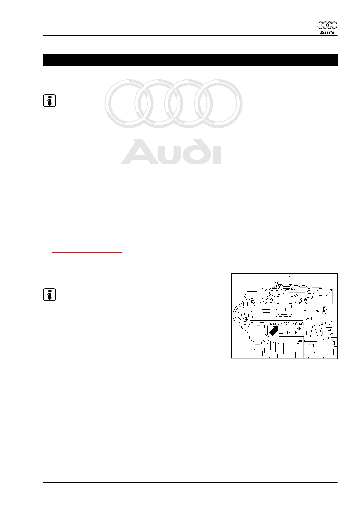
Rear final drive -02D-
Audi A3 2004 ➤ , Audi TT 2007 ➤
Note
♦
The identification -arrow- on the underside of the final drive
unit indicates which final drive version is installed.
♦
In this example: “Rear final drive 02D”
1. Rear final drive identification 1
Page 6
Protected by copyright. Copying for private or commercial purposes, in part or in whole, is not
permitted unless authorised by AUDI AG. AUDI AG does not guarantee or accept any liability
with respect to the correctness of information in this document. Copyright by AUDI AG.
Audi A3 2004 ➤ , Audi TT 2007 ➤
Rear final drive 02D, 0AV, 0BR and 0BY - Edition 06.2009
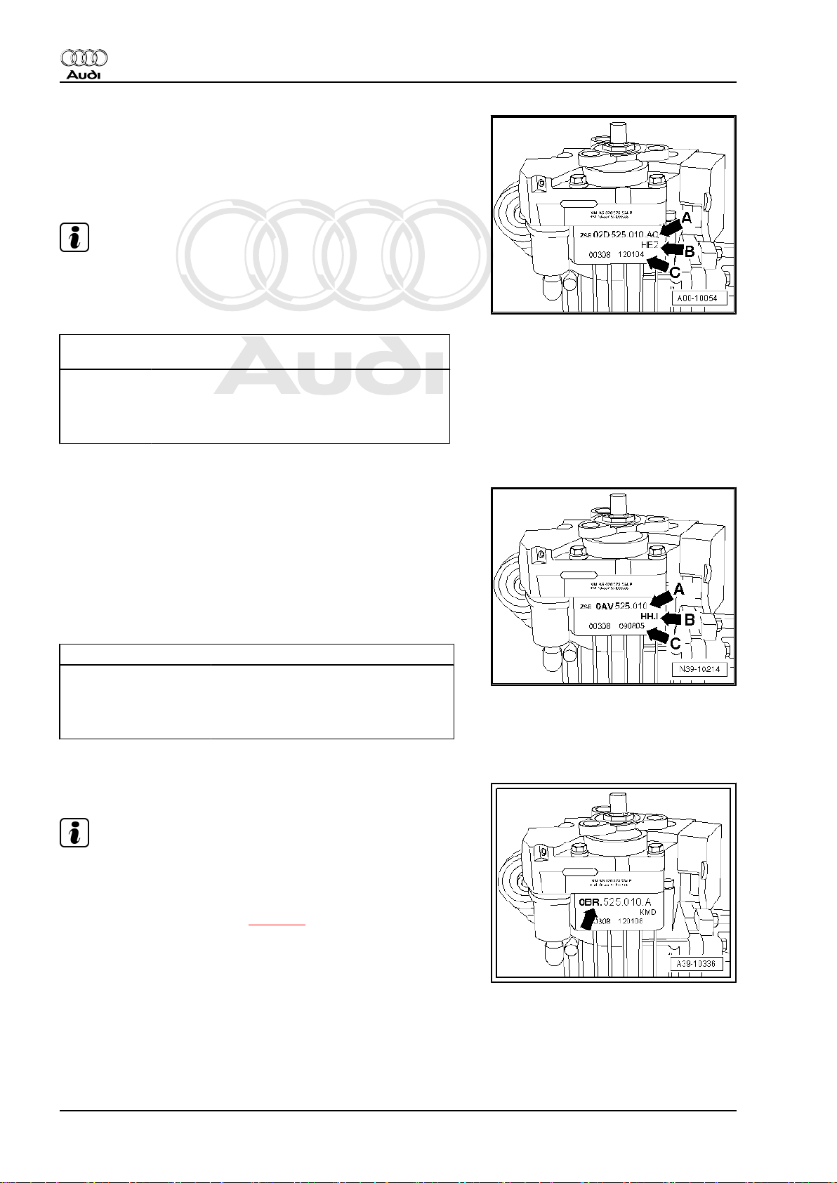
Example of identification markings on final drive “02D”
-Arrow A- Part number of final drive
-Arrow B- Code letters of final drive
-Arrow C- Production date of final drive
Note
If the code letters -arrow B- are not shown, the unit can be iden‐
tified via the Part No. -arrow A- ⇒ Electronic parts catalogue .
Example:
02D.
HEZ 12 01 04
525.010.AQ
I I I I I
I I I I I
Part No. Code let‐
ters
Day Month Year of manufacture
-2004-
Additional data are manufacture-related.
Example of identification markings on rear final drive “0AV”
-Arrow A- Part number of final drive
-Arrow B- Code letters of final drive
♦ If the code letters are not shown, the unit can be identified via
the Part No. ⇒ Electronic parts catalogue .
-Arrow C- Production date of final drive
Example:
HHJ 09 08 05
I I I I
I I I I
Code letters Day Month Year of manufacture
-2005-
Additional data are manufacture-related.
Rear final drive “0BR” or “0BY”
Note
♦
The identification -arrow- on the underside of the final drive
unit indicates which final drive version is installed.
♦
For further explanation of the identification markings on the
underside of the final drive ⇒ page 2 .
2 Rep. Gr.00 - Technical data
Page 7
Protected by copyright. Copying for private or commercial purposes, in part or in whole, is not
permitted unless authorised by AUDI AG. AUDI AG does not guarantee or accept any liability
with respect to the correctness of information in this document. Copyright by AUDI AG.
Rear final drive 02D, 0AV, 0BR and 0BY - Edition 06.2009
2 Audi A3 2004 ▸ – Code letters, allo‐
cation, transmission ratios, capaci‐
ties
⇒ “2.1 Audi A3 with rear final drive 02D/0AV”, page 3
⇒ “2.2 Audi A3 with rear final drive 0BR”, page 5
2.1 Audi A3 with rear final drive 02D/0AV
Audi A3 2004 ➤ , Audi TT 2007 ➤
Rear final drive
02D
1)
Part No. 02D.525.010.AA 02D.525.010.AC 02D.525.010.AQ
Code letters FWR HEY HEZ
Manufactured from 07.03 11.04 01.04
to 01.04 12.04 08.04
Allocation Model Audi A3 2004 ▸ Audi A3 2004 ▸ Audi A3 2004 ▸
Engine 2.0 ltr. - 147 kW
2.0 ltr. - 103 kW TDI 2.0 ltr. - 147 kW TFSI
TFSI
Ratio: Z2 : Z
1
Final drive
3.2 ltr. - 184 kW
27 : 17 = 1.588 27 : 17 = 1.588 27 : 17 = 1.588
3.2 ltr. - 184 kW
(rear)
Drive shaft flange ∅ 100 mm 100 mm 100 mm
Capacity in final drive 0.95 litres
Capacity in Haldex coupling 0.85 litres
Oil change capacity in Haldex cou‐
pling
• Change intervals: ⇒ Mainte‐
0.65 litres
nance tables “ELSA”
1)
Rear final drive “02D” is equipped with “Haldex coupling 2”
The following data can be found in the ⇒ Electronic parts catalogue
♦ Specification of gear oil for rear final drive
♦ Specification of high performance oil for Haldex coupling
♦ Allocation of gearbox
Rear final drive
0AV
1)
Part No. 0AV.525.010 0AV.525.010.A 0AV.525.010.B
Code letters HHJ HHK HVY
Manufactured from 09.05 11.04 11.05
to 11.05 11.05 05.07
Allocation Model Audi A3 2004 ▸ Audi A3 2004 ▸ Audi A3 2004 ▸
Ratio: Z2 : Z
1
Engine 2.0 ltr. - 147 kW TFSI 2.0 ltr. - 103 kW TDI 2.0 ltr. - 147 kW TFSI
3.2 ltr. - 184 kW
Final drive
3.2 ltr. - 184 kW
27 : 17 = 1.588 27 : 17 = 1.588 27 : 17 = 1.588
(rear)
Drive shaft flange ∅ 100 mm 100 mm 100 mm
Capacity in final drive 0.95 litres
Capacity in Haldex coupling 0.85 litres
2. Audi A3 2004 ▸ – Code letters, allocation, transmission ratios, capacities 3
Page 8
Protected by copyright. Copying for private or commercial purposes, in part or in whole, is not
permitted unless authorised by AUDI AG. AUDI AG does not guarantee or accept any liability
with respect to the correctness of information in this document. Copyright by AUDI AG.
Audi A3 2004 ➤ , Audi TT 2007 ➤
Rear final drive 02D, 0AV, 0BR and 0BY - Edition 06.2009
Rear final drive
0AV
1)
Part No. 0AV.525.010 0AV.525.010.A 0AV.525.010.B
Code letters HHJ HHK HVY
Oil change capacity in Haldex cou‐
0.65 litres
pling
• Change intervals: ⇒ Mainte‐
nance tables “ELSA”
1)
Rear final drive “0AV” is equipped with “Haldex coupling 2”
The following data can be found in the ⇒ Electronic parts catalogue
♦ Specification of gear oil for rear final drive
♦ Specification of high performance oil for Haldex coupling
♦ Allocation of gearbox
Rear final drive
0AV
1)
Part No. 0AV.525.010.C 0AV.525.010.D 0AV.525.010.E
Code letters HVZ JJN JYP
Manufactured from 11.05 11.06 06.07
to 05.07 01.08 02.08
Allocation Model Audi A3 2004 ▸ Audi A3 2004 ▸ Audi A3 2004 ▸
Ratio: Z2 : Z
1
Engine 2.0 ltr. - 103 kW TDI 2.0 ltr. - 147 kW TFSI
2.0 ltr. - 195 kW TFSI
2.0 ltr. - 125 kW TDI 3.2 ltr. - 184 kW 2.0 ltr. - 125 kW TDI
Final drive
27 : 17 = 1.588 27 : 17 = 1.588 27 : 17 = 1.588
2.0 ltr. - 103 kW TDI
(rear)
Drive shaft flange ∅ 100 mm 100 mm 100 mm
Capacity in final drive 0.95 litres
Capacity in Haldex coupling 0.85 litres
Oil change capacity in Haldex cou‐
0.65 litres
pling
• Change intervals: ⇒ Mainte‐
nance tables “ELSA”
1)
Rear final drive “0AV” is equipped with “Haldex coupling 2”
The following data can be found in the ⇒ Electronic parts catalogue
♦ Specification of gear oil for rear final drive
♦ Specification of high performance oil for Haldex coupling
♦ Allocation of gearbox
Rear final drive
0AV
1)
Part No. 0AV.525.010.K 0AV.525.010.L
Code letters KJS KJT
Manufactured from 09.07 02.08
to 06.08 06.08
Allocation Model Audi A3 2004 ▸ Audi A3 2004 ▸
Engine 2.0 ltr. - 147 kW TFSI
2.0 ltr. - 103 kW TDI
2.0 ltr. - 195 kW TFSI
3.2 ltr. - 184 kW 2.0 ltr. - 125 kW TDI
4 Rep. Gr.00 - Technical data
Page 9
Protected by copyright. Copying for private or commercial purposes, in part or in whole, is not
permitted unless authorised by AUDI AG. AUDI AG does not guarantee or accept any liability
with respect to the correctness of information in this document. Copyright by AUDI AG.
Audi A3 2004 ➤ , Audi TT 2007 ➤
Rear final drive 02D, 0AV, 0BR and 0BY - Edition 06.2009
Rear final drive
0AV
1)
Part No. 0AV.525.010.K 0AV.525.010.L
Code letters KJS KJT
Ratio: Z2 : Z
1
Final
27 : 17 = 1.588 27 : 17 = 1.588
drive
(rear)
Drive shaft flange ∅ 100 mm 100 mm
Capacity in final drive 0.95 litres
Capacity in Haldex coupling 0.85 litres
Oil change capacity in Haldex
0.65 litres
coupling
• Change intervals: ⇒ Main‐
tenance tables “ELSA”
1)
Rear final drive “0AV” is equipped with “Haldex coupling 2”
The following data can be found in the ⇒ Electronic parts catalogue
♦ Specification of gear oil for rear final drive
♦ Specification of high performance oil for Haldex coupling
♦ Allocation of gearbox
2.2 Audi A3 with rear final drive 0BR
Rear final drive
Part No. 0BR.525.010
Code letters KMC
Manufac‐
from 07.08
tured
to
Allocation ModelAudi A3 2004
▸
En‐
gine
1.8 ltr. - 118
kW TFSI
2.0 ltr. - 147
kW TFSI
2.0 ltr. - 188
kW TFSI
2.0 ltr. - 195
kW TFSI
3.2 ltr. - 184
kW
2.0 ltr. - 103
kW TDI
Ratio: Z2 :
Z
1
Fi‐
nal
driv
27 : 17 =
1.588
e
(rear
)
Drive shaft flange∅100 mm
1)
0BR
Capacity in final
drive
Capacity in Hal‐
dex coupling
0.95 litres
0.85 litres
2. Audi A3 2004 ▸ – Code letters, allocation, transmission ratios, capacities 5
Page 10
Protected by copyright. Copying for private or commercial purposes, in part or in whole, is not
permitted unless authorised by AUDI AG. AUDI AG does not guarantee or accept any liability
with respect to the correctness of information in this document. Copyright by AUDI AG.
Audi A3 2004 ➤ , Audi TT 2007 ➤
Rear final drive 02D, 0AV, 0BR and 0BY - Edition 06.2009
Rear final drive
Part No. 0BR.525.010
Code letters KMC
Oil change ca‐
1)
0BR
0.70 litres
pacity in Haldex
coupling
• Change inter‐
vals: ⇒ Main‐
tenance ta‐
bles “ELSA”
1)
Rear final drive “0BR” is equipped with “Haldex coupling 4”
The following data can be found in the ⇒ Electronic parts
catalogue
♦ Specification of gear oil for rear final drive
♦ Specification of high performance oil for Haldex coupling
♦ Allocation of gearbox
6 Rep. Gr.00 - Technical data
Page 11
Protected by copyright. Copying for private or commercial purposes, in part or in whole, is not
permitted unless authorised by AUDI AG. AUDI AG does not guarantee or accept any liability
with respect to the correctness of information in this document. Copyright by AUDI AG.
Rear final drive 02D, 0AV, 0BR and 0BY - Edition 06.2009
3 Audi TT 2007▸ – Code letters, allo‐
cation, transmission ratios, capaci‐
ties
⇒ “3.1 Audi TT with rear final drive 02D/0AV”, page 7
⇒ “3.2 Audi TT with rear final drive 0BR”, page 8
⇒ “3.3 Audi TT RS with rear final drive 0BY”, page 9
3.1 Audi TT with rear final drive 02D/0AV
Audi A3 2004 ➤ , Audi TT 2007 ➤
Rear final drive
0AV
1)
Part No. 0AV.525.010.B 0AV.525.010.D 0AV.525.010.F
Code letters HVY JJN JUY
Manufactured from 11.05 11.06 03.07
to 05.07 - -
Allocation Model Audi TT 2007 ▸ Audi TT 2007 ▸ Audi TT 2007 ▸
Engine
3.2 ltr. - 184 kW 3.2 ltr. - 184 kW 3.2 ltr. - 184 kW
Ratio: Z2 : Z
1
Final drive
27 : 17 = 1.588 27 : 17 = 1.588 27 : 17 = 1.588
(rear)
Drive shaft flange ∅ 100 mm 100 mm 100 mm
Capacity in final drive 0.95 litres
Capacity in Haldex coupling 0.85 litres
Oil change capacity in Haldex cou‐
pling
0.65 litres
• Change intervals: ⇒ Mainte‐
nance tables “ELSA”
1)
Rear final drive “0AV” is equipped with “Haldex coupling 2”
The following data can be found in the ⇒ Electronic parts catalogue
♦ Specification of gear oil for rear final drive
♦ Specification of high performance oil for Haldex coupling
♦ Allocation of gearbox
Rear final drive
0AV
1)
Part No. 0AV.525.010.H 0AV.525.010.K 0AV.525.010.M
Code letters JZX KJS KJU
Manufactured from 08.06 12.07 12.07
to 11.06 - -
Allocation Model Audi TT 2007 ▸ Audi TT 2007 ▸ Audi TT 2007 ▸
Engine
3.2 ltr. - 184 kW 3.2 ltr. - 184 kW 3.2 ltr. - 184 kW
Ratio: Z2 : Z
1
Final drive
27 : 17 = 1.588 27 : 17 = 1.588 27 : 17 = 1.588
(rear)
Drive shaft flange ∅ 100 mm 100 mm 100 mm
Capacity in final drive 0.95 litres
Capacity in Haldex coupling 0.85 litres
3. Audi TT 2007▸ – Code letters, allocation, transmission ratios, capacities 7
Page 12
Protected by copyright. Copying for private or commercial purposes, in part or in whole, is not
permitted unless authorised by AUDI AG. AUDI AG does not guarantee or accept any liability
with respect to the correctness of information in this document. Copyright by AUDI AG.
Audi A3 2004 ➤ , Audi TT 2007 ➤
Rear final drive 02D, 0AV, 0BR and 0BY - Edition 06.2009
Rear final drive
0AV
1)
Part No. 0AV.525.010.H 0AV.525.010.K 0AV.525.010.M
Code letters JZX KJS KJU
Oil change capacity in Haldex cou‐
0.65 litres
pling
• Change intervals: ⇒ Mainte‐
nance tables “ELSA”
1)
Rear final drive “0AV” is equipped with “Haldex coupling 2”
The following data can be found in the ⇒ Electronic parts catalogue
♦ Specification of gear oil for rear final drive
♦ Specification of high performance oil for Haldex coupling
♦ Allocation of gearbox
3.2 Audi TT with rear final drive 0BR
Rear final drive
Part No. 0BR.525.010 0BR.
Code letters KMC KMD
Manufac‐
from 01.08 01.08
tured
to
Allocation ModelAudi TT 2007▸Audi TT 2007
En‐
gine
2.0 ltr. - 195
kW TFSI
2.0 ltr. - 199
2.0 ltr. - 195
2.0 ltr. - 199
kW TFSI
Ratio: Z2 :
Z
1
3.2 ltr. - 184kW3.2 ltr. - 184
Fi‐
27 : 17 =
nal
1.588
driv
e
(rear
)
Drive shaft flange∅100 mm 100 mm
1)
0BR
525.010.A
-
▸
kW TFSI
kW TFSI
kW
27 : 17 =
1.588
Capacity in final
0.95 litres
drive
Capacity in Hal‐
0.85 litres
dex coupling
Oil change ca‐
0.70 litres
pacity in Haldex
coupling
• Change inter‐
vals: ⇒ Main‐
tenance ta‐
bles “ELSA”
1)
Rear final drive “0BR” is equipped with “Haldex coupling 4”
8 Rep. Gr.00 - Technical data
Page 13

Protected by copyright. Copying for private or commercial purposes, in part or in whole, is not
permitted unless authorised by AUDI AG. AUDI AG does not guarantee or accept any liability
with respect to the correctness of information in this document. Copyright by AUDI AG.
Audi A3 2004 ➤ , Audi TT 2007 ➤
Rear final drive 02D, 0AV, 0BR and 0BY - Edition 06.2009
Rear final drive
Part No. 0BR.525.010 0BR.
0BR
1)
525.010.A
Code letters KMC KMD
The following data can be found in the ⇒ Electronic parts
catalogue
♦ Specification of gear oil for rear final drive
♦ Specification of high performance oil for Haldex coupling
♦ Allocation of gearbox
3.3 Audi TT RS with rear final drive 0BY
Rear final drive
Part No. 0BY.525.010
Code letters LEK
Manufac‐
from 01.09
tured
to
Allocation ModelAudi TT RS
2007▸
En‐
gine
2.5 ltr. - 250
kW TFSI
Ratio: Z2 :
Z
1
Fi‐
nal
driv
27 : 17 =
1.588
e
(rear
)
Drive shaft flange∅100 mm
1)
0BY
Capacity in final
0.95 litres
drive
Capacity in Hal‐
0.85 litres
dex coupling
Oil change ca‐
0.70 litres
pacity in Haldex
coupling
• Change inter‐
vals: ⇒ Main‐
tenance ta‐
bles “ELSA”
1)
Rear final drive “0BY” is equipped with “Haldex coupling 4”
The following data can be found in the ⇒ Electronic parts
catalogue
♦ Specification of gear oil for rear final drive
♦ Specification of high performance oil for Haldex coupling
♦ Allocation of gearbox
3. Audi TT 2007▸ – Code letters, allocation, transmission ratios, capacities 9
Page 14
Protected by copyright. Copying for private or commercial purposes, in part or in whole, is not
permitted unless authorised by AUDI AG. AUDI AG does not guarantee or accept any liability
with respect to the correctness of information in this document. Copyright by AUDI AG.
Audi A3 2004 ➤ , Audi TT 2007 ➤
Rear final drive 02D, 0AV, 0BR and 0BY - Edition 06.2009
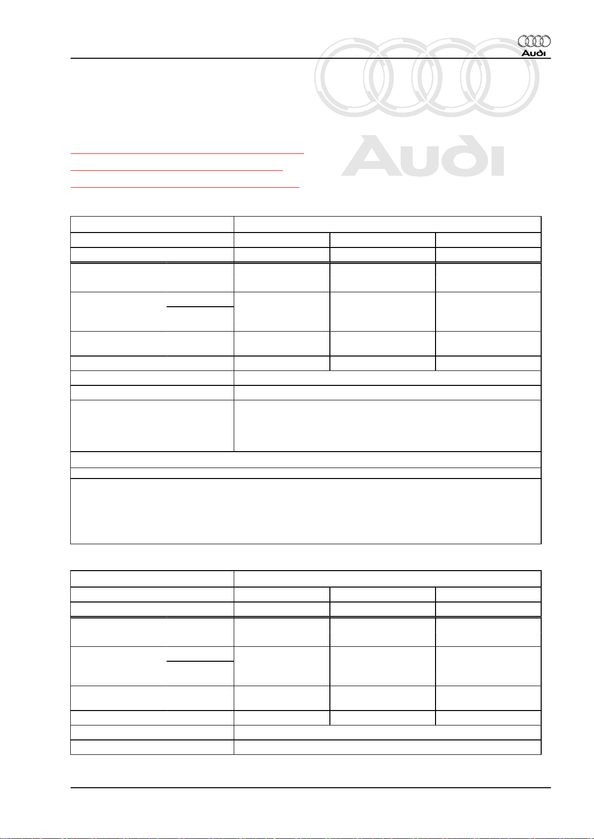
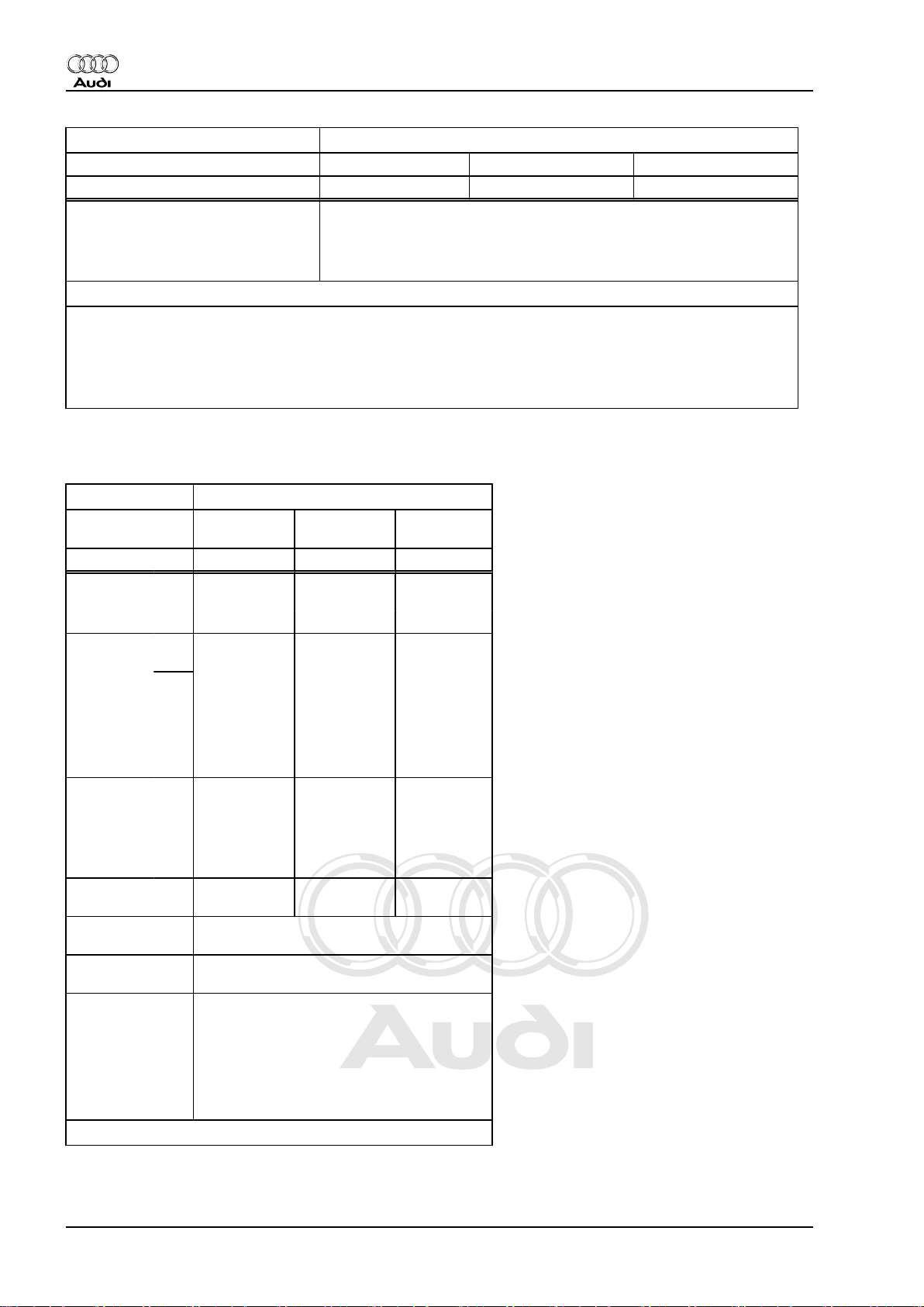
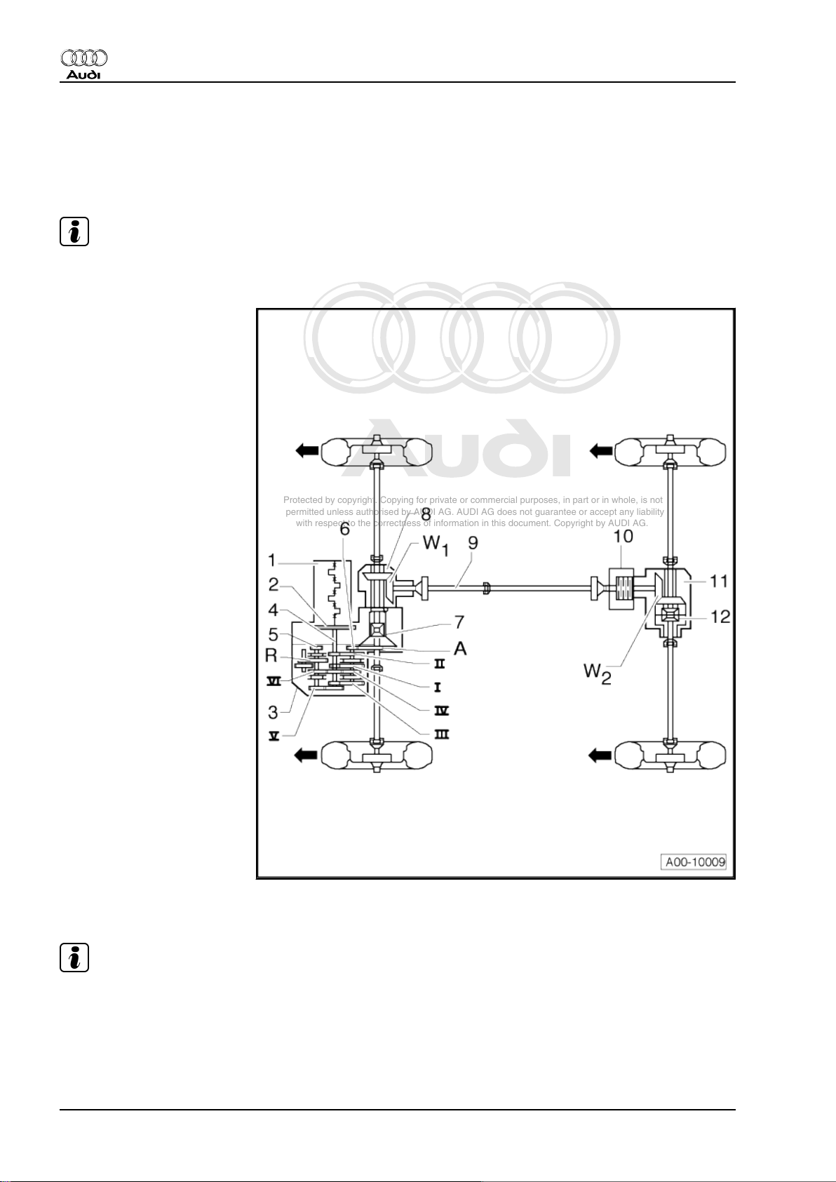
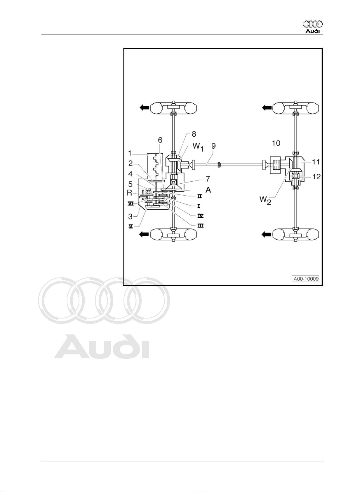
4 Transmission layout
♦ Illustrated with 6-speed manual gearbox 02Q, four-wheel drive
Identification
Note
Arrows point in direction of travel.
1 - Engine
2 - Clutch
3 - Manual gearbox or direct
shift gearbox
4 - Input shaft
5 - Output shaft for 5th, 6th and
reverse gear
6 - Output shaft for 1st - 4th
gear
7 - Differential
8 - Bevel box
9 - Propshaft
10 - Haldex coupling
11 - Rear final drive
12 - Differential
Ratio
Note
Arrows point in direction of travel.
10 Rep. Gr.00 - Technical data
Page 15
Protected by copyright. Copying for private or commercial purposes, in part or in whole, is not
permitted unless authorised by AUDI AG. AUDI AG does not guarantee or accept any liability
with respect to the correctness of information in this document. Copyright by AUDI AG.
I - 1st gear
II - 2nd gear
III - 3rd gear
IV - 4th gear
V - 5th gear
VI - 6th gear
R - Reverse gear
A - Final drive
W 1 - Front bevel gears
W 2 - Rear bevel gears
Audi A3 2004 ➤ , Audi TT 2007 ➤
Rear final drive 02D, 0AV, 0BR and 0BY - Edition 06.2009
4. Transmission layout 11
Page 16
Protected by copyright. Copying for private or commercial purposes, in part or in whole, is not
permitted unless authorised by AUDI AG. AUDI AG does not guarantee or accept any liability
with respect to the correctness of information in this document. Copyright by AUDI AG.
Audi A3 2004 ➤ , Audi TT 2007 ➤
Rear final drive 02D, 0AV, 0BR and 0BY - Edition 06.2009
5 General repair instructions
Proper tools and the maximum possible care and cleanliness are
essential for satisfactory repairs to the final drive. The usual basic
safety precautions also naturally apply when carrying out repair
work.
A number of generally applicable instructions for the various re‐
pair procedures are summarised here under the designation
“Components” ⇒ page 14 . They apply to the work described in
this Manual.
5.1 Gear oil and oil for Haldex coupling
Caution
The final drive and the “Haldex coupling” have separate oil cir‐
cuits.
♦ The Haldex coupling is filled with high-performance oil for
Haldex coupling . For part number, refer to ⇒ Electronic
parts catalogue .
♦ The final drive is filled with “gear oil”. For part number,
refer to ⇒ Electronic parts catalogue .
12 Rep. Gr.00 - Technical data
Page 17
Protected by copyright. Copying for private or commercial purposes, in part or in whole, is not
permitted unless authorised by AUDI AG. AUDI AG does not guarantee or accept any liability
with respect to the correctness of information in this document. Copyright by AUDI AG.
Rear final drive 02D, 0AV, 0BR and 0BY - Edition 06.2009
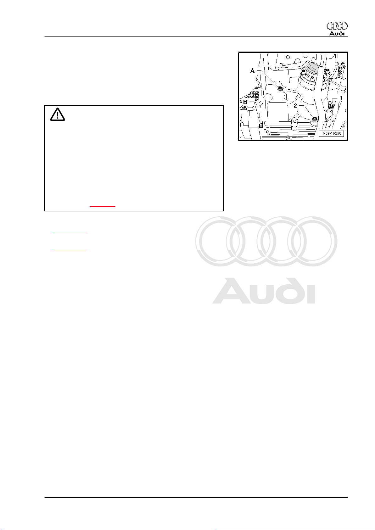
Location of oil filler plugs and drain plugs
A - Filler plug for high performance oil for Haldex coupling
B - Drain plug for high performance oil for Haldex coupling
1 - Filler plug for gear oil
2 - Drain plug for gear oil
Caution
Different types of high-performance oil for Haldex coupling
♦ The rear final drive units “02D/0AV” and “0BR/0BY” have
different “Haldex couplings” and therefore different types
of oil for the Haldex coupling.
♦ The two different types of oil for the Haldex couplings must
not be interchanged or mixed together.
♦ Part number for high performance oil for Haldex coupling
⇒ Electronic parts catalogue .
♦ Note the distinguishing markings for the different rear final
drive units ⇒ page 1 .
Audi A3 2004 ➤ , Audi TT 2007 ➤
♦ Checking oil level in rear final drive and topping up
⇒ page 123 .
♦ Checking oil level in Haldex coupling and topping up
⇒ page 115 .
♦ Do not use any “additives” in the oil.
♦ Do not re-use oil that has been drained off.
Regulations for the disposal of oil
Drained oil must be disposed of properly.
♦ Improper disposal of used oil endangers the environment.
♦ It must not be mixed with solvents, brake fluid, coolant or sim‐
ilar.
♦ Please observe the information shown on the packaging of the
oil.
5. General repair instructions 13
Page 18
Protected by copyright. Copying for private or commercial purposes, in part or in whole, is not
permitted unless authorised by AUDI AG. AUDI AG does not guarantee or accept any liability
with respect to the correctness of information in this document. Copyright by AUDI AG.
Audi A3 2004 ➤ , Audi TT 2007 ➤
Rear final drive 02D, 0AV, 0BR and 0BY - Edition 06.2009
5.2 Components
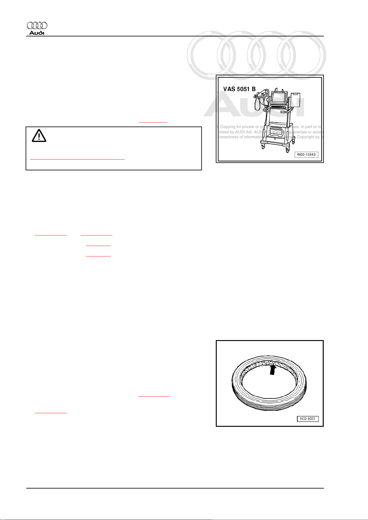
Guided fault finding, vehicle self-diagnosis and testing system
♦ Before servicing the Haldex coupling, the exact cause of the
failure must be determined as precisely as possible via the
vehicle diagnostic, testing and information system -VAS
5051B- in the modes “Guided Fault Finding”, “vehicle self-di‐
agnosis” and “testing system”.
– Connecting vehicle diagnostic, testing and information system
- VAS 5051B- and selecting functions ⇒ page 53 .
WARNING
To avoid any risk of accident, observe the
⇒ “6 Safety precautions”, page 16 when road-testing the ve‐
hicle and using test equipment.
Special tools
For a complete list of special tools used in this Workshop Manual
⇒ "Workshop equipment and special tools" .
Rear final drive
♦ When renewing the rear final drive, check gear oil level and oil
level of the Haldex coupling and top up if necessary:
⇒ page 123 and ⇒ page 115 .
♦ Capacity, Audi A3 ⇒ page 3 .
♦ Capacity, Audi TT ⇒ page 7 .
♦ Specifications ⇒ Electronic parts catalogue .
♦ When installing mounting brackets as well as other waxed
components, the contact surfaces must be cleaned. The con‐
tact surfaces must be free of wax and grease.
O-rings, oil seals and gaskets
♦ Always renew O-rings, seals and gaskets.
♦ Thoroughly clean joint surfaces.
Before installation:
♦ Before installing oil seals, lightly oil outer circumference and
fill space between sealing lips -arrow- with a thin layer of
grease.
♦ The open side of the oil seals faces toward the side with fluid
filling.
After installation:
♦ Check gear oil level in rear final drive ⇒ page 123 .
♦ Check oil level in Haldex coupling and top up as necessary
⇒ page 115 .
Locking elements
14 Rep. Gr.00 - Technical data
Page 19
Protected by copyright. Copying for private or commercial purposes, in part or in whole, is not
permitted unless authorised by AUDI AG. AUDI AG does not guarantee or accept any liability
with respect to the correctness of information in this document. Copyright by AUDI AG.
Rear final drive 02D, 0AV, 0BR and 0BY - Edition 06.2009
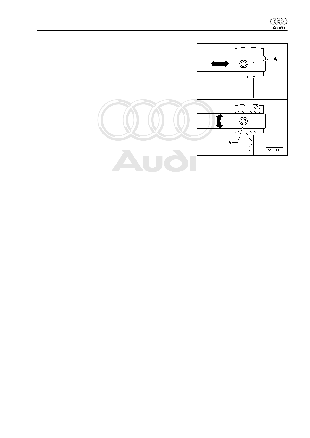
♦ Do not over-stretch circlips.
♦ Always renew circlips which have been damaged or over-
stretched.
♦ Circlips must be properly seated in the base of the groove.
♦ Renew spring pins. Position: the slit -A- should be in line with
the line of force -arrow-.
Nuts, bolts
♦ Nuts and bolts for securing covers and housings must be
slackened and tightened in diagonal sequence.
♦ Loosen and tighten particularly sensitive parts in diagonal se‐
quence and in stages, taking care to keep them straight.
♦ The tightening torques stated apply to non-oiled nuts and
bolts.
♦ Always renew self-locking bolts and nuts.
♦ For all threaded connections, ensure that (where applicable)
the contact surfaces and the nuts and bolts are not coated with
wax until after assembly is completed.
Bearings
♦ Install needle bearings so the lettering (side with thicker metal)
faces towards the installing tool.
♦ Lubricate all bearings in final drive with gear oil when installing.
♦ Always renew the tapered roller bearings on one shaft togeth‐
er as a set and use new bearings from a single manufacturer.
♦ Heat inner races to approx. 100° C before installing.
♦ Do not interchange the outer or inner races of bearings of the
same size (the bearings are paired).
Shims
♦ Measure shims at several points with a micrometer. Tolerance
variations make it possible to obtain the exact shim thickness
required.
♦ Check for burrs and damage.
♦ Install only shims which are in perfect condition.
Audi A3 2004 ➤ , Audi TT 2007 ➤
5.3 Contact corrosion!
Contact corrosion can occur if non-approved fasteners are used
on the vehicle (bolts, nuts, washers etc.).
For this reason, only fasteners with a special surface coating are
fitted.
Rubber or plastic parts and adhesives also consist of non-con‐
ductive materials.
If you are not sure whether used parts can be re-installed, always
fit new parts ⇒ Electronic parts catalogue .
Please note:
♦ Use only genuine spare parts: these have been fully tested
and are compatible with aluminium.
♦ We recommend the use of accessories approved by Audi.
♦ Damage resulting from contact corrosion is not covered by the
warranty.
5. General repair instructions 15
Page 20
Protected by copyright. Copying for private or commercial purposes, in part or in whole, is not
permitted unless authorised by AUDI AG. AUDI AG does not guarantee or accept any liability
with respect to the correctness of information in this document. Copyright by AUDI AG.
Audi A3 2004 ➤ , Audi TT 2007 ➤
Rear final drive 02D, 0AV, 0BR and 0BY - Edition 06.2009
6 Safety precautions
⇒ “6.1 Safety precautions for Audi TT and Audi A3 Cabriolet”,
page 16
⇒ “6.2 Safety precautions for Audi A3”, page 17
6.1 Safety precautions for Audi TT and Audi A3 Cabriolet
Observe the following precautions if tests have to be performed
with the engine running.
WARNING
Vehicles with dual clutch gearbox: accidents can be caused if
a gear is inadvertently engaged while the engine is running.
♦ Before working on the vehicle while the engine is running,
shift the selector lever into position “P” and apply the
handbrake.
Danger from toxic fumes!
♦ When the engine is running, the exhaust system must al‐
ways be connected to the exhaust gas extractor.
16 Rep. Gr.00 - Technical data
Page 21
Protected by copyright. Copying for private or commercial purposes, in part or in whole, is not
permitted unless authorised by AUDI AG. AUDI AG does not guarantee or accept any liability
with respect to the correctness of information in this document. Copyright by AUDI AG.
Rear final drive 02D, 0AV, 0BR and 0BY - Edition 06.2009
Observe the following precautions if test equipment has to be
used while road-testing the vehicle:
WARNING
Accidents can be caused if the driver is distracted by test
equipment while road-testing, or if test equipment is not se‐
cured.
Injuries can also be caused if the passenger's airbag is trig‐
gered in a collision.
• The use of test equipment while driving causes distraction.
• There is an increased risk of injury if test equipment is not
secured.
TT Coupé:
Always secure testing equipment to the rear seat with a strap
and have them operated from there by a second person.
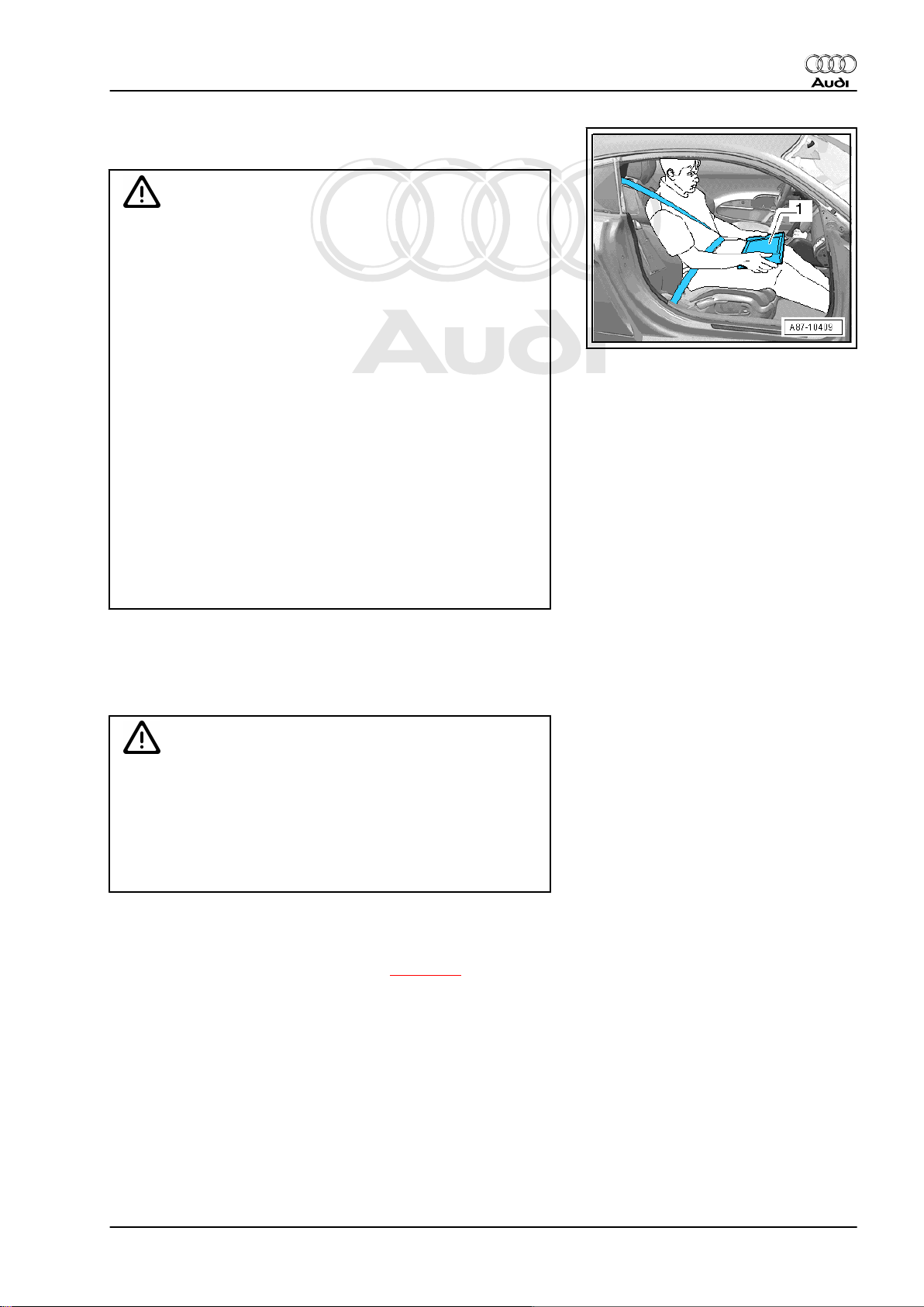
TT Roadster:
♦ Move the passenger's seat to the rearmost position.
♦ Use only vehicle diagnosis and service information sys‐
tem -VAS 5052- or diagnosis system -VAS 5053- .
♦ Test equipment may only be operated by the passenger;
the tester -1- must be placed flat on the passenger's lap
as illustrated.
Audi A3 2004 ➤ , Audi TT 2007 ➤
Observe the following precautions to avoid possible injury and/or
damage to electrical and electronic components:
♦ Switch off ignition before disconnecting and connecting test
equipment.
Caution
When disconnecting the battery there is a risk of serious dam‐
age to electronic components:
♦ Observe the correct procedure for disconnecting the bat‐
tery.
♦ Always switch off the ignition before disconnecting the
battery.
6.2 Safety precautions for Audi A3
Safety precautions for Audi A3 Cabriolet ⇒ page 16
6. Safety precautions 17
Page 22
Protected by copyright. Copying for private or commercial purposes, in part or in whole, is not
permitted unless authorised by AUDI AG. AUDI AG does not guarantee or accept any liability
with respect to the correctness of information in this document. Copyright by AUDI AG.
Audi A3 2004 ➤ , Audi TT 2007 ➤
Rear final drive 02D, 0AV, 0BR and 0BY - Edition 06.2009
Observe the following precautions to avoid possible injury and/or
damage to the vehicle:
WARNING
Vehicles with dual clutch gearbox: accidents and injury can be
caused if a gear is inadvertently engaged while the engine is
running.
♦ Before working on the vehicle while the engine is running,
shift the selector lever into position “P” and apply the
handbrake.
Danger from toxic fumes!
♦ When the engine is running, the exhaust system must al‐
ways be connected to the exhaust gas extractor.
Observe the following precautions if test equipment has to be
used when road-testing the vehicle.
WARNING
Accidents can be caused if the driver is distracted by test
equipment or if test equipment is not secured.
Injuries can be caused if the passenger's airbag is triggered in
a collision.
• The use of test equipment while driving causes distraction.
• There is an increased risk of injury if test equipment is not
secured.
♦ Always secure testing equipment to the rear seat with a
strap and have them operated from there by a second
person.
Observe the following precautions to avoid possible injury and/or
irreparable damage to electrical and electronic components:
♦ Switch off ignition before disconnecting and connecting test
equipment.
Caution
When disconnecting the battery there is a risk of serious dam‐
age to electronic components:
♦ Observe the correct procedure for disconnecting the bat‐
tery.
♦ Always switch off the ignition before disconnecting the
battery.
– Disconnect battery ⇒ Rep. Gr. 27 .
18 Rep. Gr.00 - Technical data
Page 23
Protected by copyright. Copying for private or commercial purposes, in part or in whole, is not
permitted unless authorised by AUDI AG. AUDI AG does not guarantee or accept any liability
with respect to the correctness of information in this document. Copyright by AUDI AG.
Rear final drive 02D, 0AV, 0BR and 0BY - Edition 06.2009
39 – Final drive - rear differential
1 Exploded view – propshaft with de‐
tachable centre bearing (up to 05.07)
The propshaft with detachable centre bearing was installed as
follows:
♦ Audi TT up to vehicle identification number 8J-8-011 000
♦ Audi A3 up to and including model year 2007
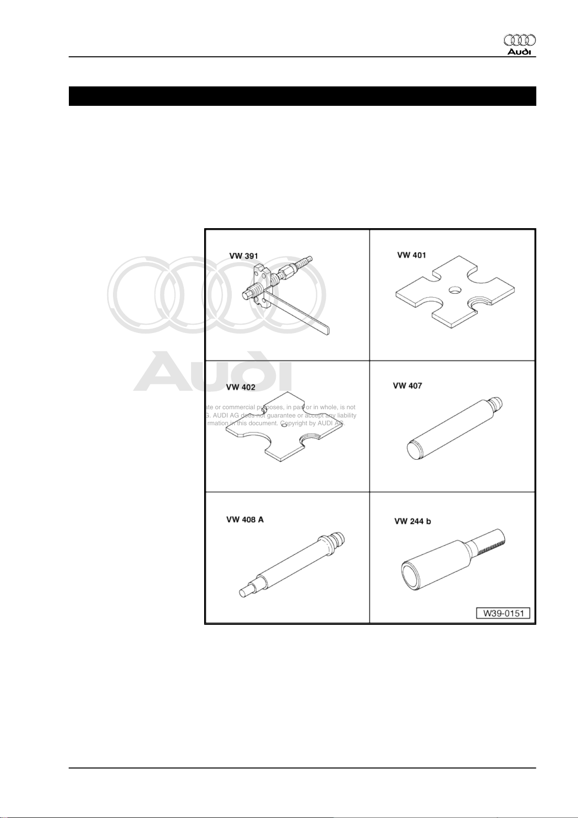
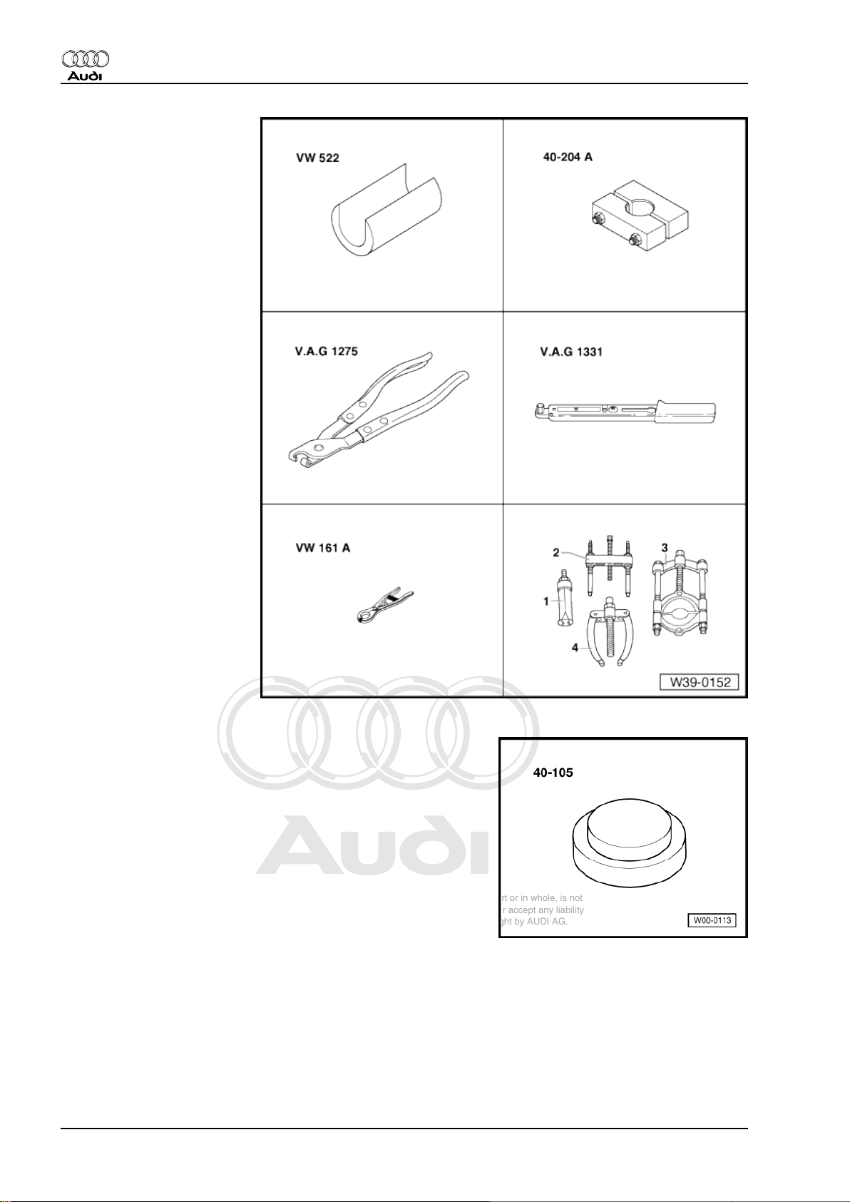
Special tools and workshop
equipment required
♦ Drive flange installing tool -
VW 391-
♦ Thrust plate -VW 401-
♦ Thrust plate -VW 402-
♦ Press tool -VW 407-
♦ Press tool -VW 408A-
♦ Drift sleeve -VW 244B-
Audi A3 2004 ➤ , Audi TT 2007 ➤
1. Exploded view – propshaft with detachable centre bearing (up to 05.07) 19
Page 24
Protected by copyright. Copying for private or commercial purposes, in part or in whole, is not
permitted unless authorised by AUDI AG. AUDI AG does not guarantee or accept any liability
with respect to the correctness of information in this document. Copyright by AUDI AG.
Audi A3 2004 ➤ , Audi TT 2007 ➤
Rear final drive 02D, 0AV, 0BR and 0BY - Edition 06.2009
♦ Support sleeve -VW 522-
♦ Tensioner -40-204A-
♦ Hose clip pliers -V.A.G
1275/-
♦ Torque wrench -V.A.G
1331/-
♦ Circlip pliers -VW 161A-
♦ Puller -2 - Kukko 18/0-
♦ Splitter -3 - Kukko 17/1-
♦ Thrust plate -40 - 105-
20 Rep. Gr.39 - Final drive - rear differential
Page 25
Protected by copyright. Copying for private or commercial purposes, in part or in whole, is not
permitted unless authorised by AUDI AG. AUDI AG does not guarantee or accept any liability
with respect to the correctness of information in this document. Copyright by AUDI AG.
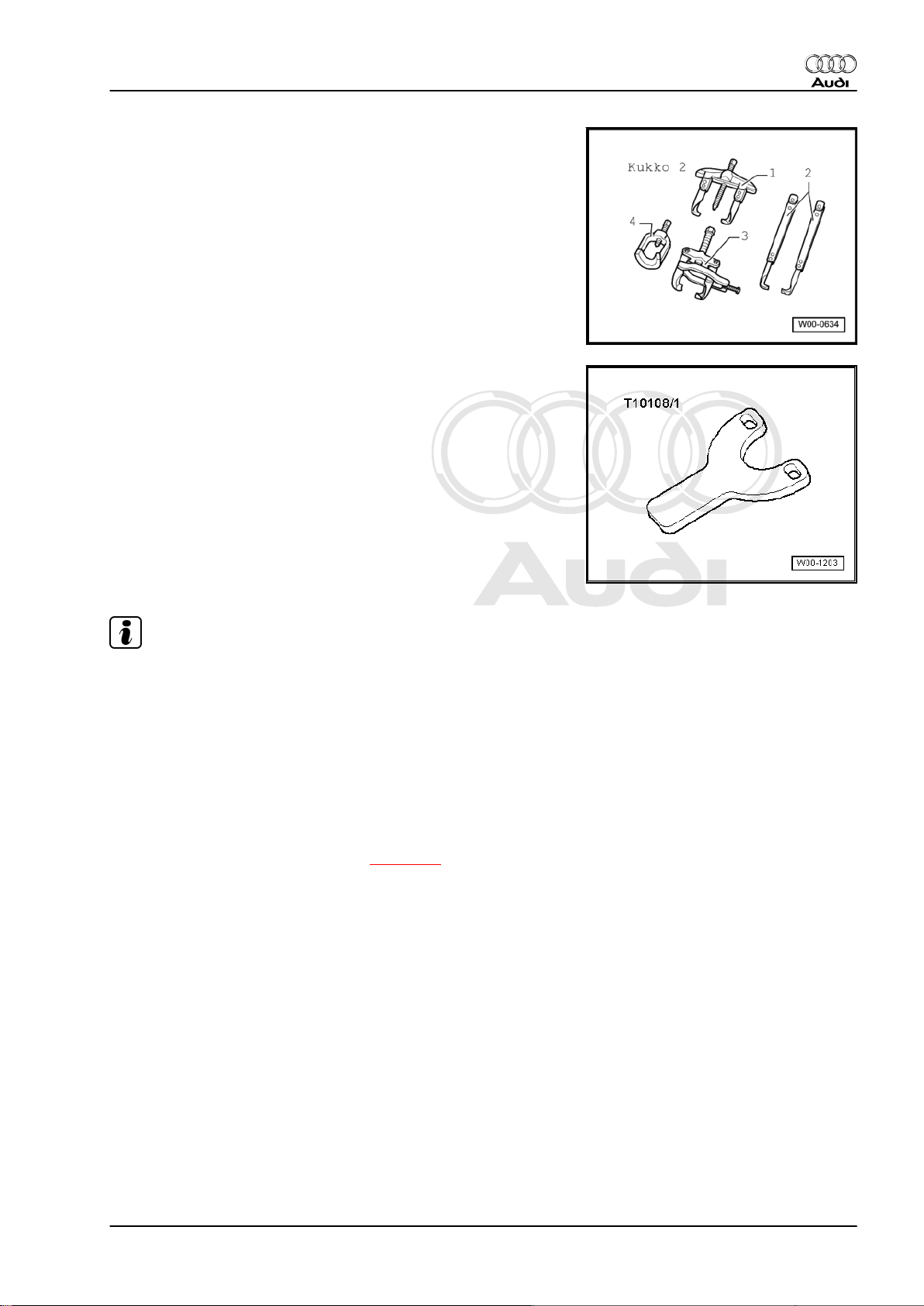
♦ Two-arm puller -1 Kukko 20/10-
♦ Support plate -T10108/1-
Audi A3 2004 ➤ , Audi TT 2007 ➤
Rear final drive 02D, 0AV, 0BR and 0BY - Edition 06.2009
Note
♦
In order to achieve the quietest possible running, only the
complete propshaft is balanced during manufacture. The bal‐
ancing of the complete propshaft or the individual propshaft
tubes cannot be carried out with workshop equipment. There‐
fore, if the front or rear propshaft tube is damaged, always
renew the complete propshaft.
♦
Do not bend propshaft; only store and transport fully extended.
♦
Before removing, mark the positions of all parts in relation to
each other. Reinstall in the same position to avoid excessive
imbalance, resulting in bearing damage and rumbling noise.
♦
Removing and installing propshaft ⇒ page 27
1. Exploded view – propshaft with detachable centre bearing (up to 05.07) 21
Page 26
Protected by copyright. Copying for private or commercial purposes, in part or in whole, is not
permitted unless authorised by AUDI AG. AUDI AG does not guarantee or accept any liability
with respect to the correctness of information in this document. Copyright by AUDI AG.
Audi A3 2004 ➤ , Audi TT 2007 ➤
Rear final drive 02D, 0AV, 0BR and 0BY - Edition 06.2009
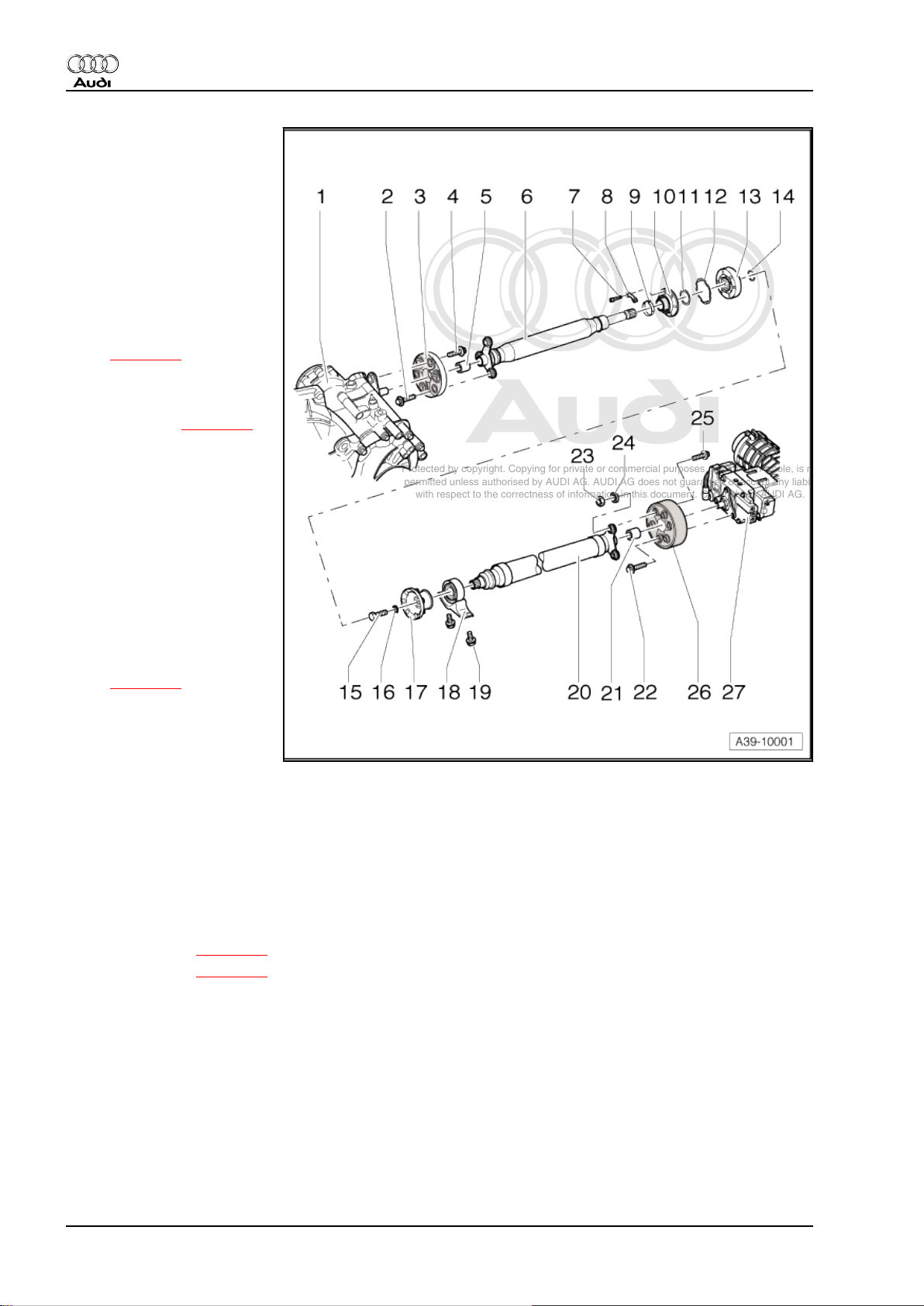
1 - Manual gearbox with bevel
box
2 - Bolt
❑ 50 Nm + 90°
❑ Always renew
3 - Flexible coupling with heat
shield
❑ Installation position:
open side of heat shield
points towards gearbox
❑ Removing and installing
⇒ page 27
4 - Bolt
❑ 60 Nm
❑ Allocation ⇒ page 31
5 - Centring sleeve
6 - Propshaft tube (front)
❑ Do not damage centring
sleeve -5- and seal in
centre of flange when
removing and installing
7 - Bolt
❑ 40 Nm
8 - Lock plate
9 - Clip
❑ Tensioning
⇒ page 24
10 - Boot for constant velocity
joint
❑ Drive off with a drift be‐
fore pressing off CV joint
❑ Check for damage
11 - Dished spring
❑ Inner diameter serrated
❑ Installation position: large diameter lies against CV joint
12 - Gasket
❑ Renew; pull off backing and stick onto joint
13 - Constant velocity joint
❑ Pressing off ⇒ page 23
❑ Pressing on ⇒ page 24
❑ Press 25 g G-6.3 grease from each side (in total 50 g) into joint. Regrease joint if necessary when
renewing boot
14 - Circlip
❑ Renew
❑ Remove and install using circlip pliers -VW 161A-
15 - Bolt
❑ 45 Nm
16 - Washer
❑ Always renew
22 Rep. Gr.39 - Final drive - rear differential
Page 27
Protected by copyright. Copying for private or commercial purposes, in part or in whole, is not
permitted unless authorised by AUDI AG. AUDI AG does not guarantee or accept any liability
with respect to the correctness of information in this document. Copyright by AUDI AG.
Audi A3 2004 ➤ , Audi TT 2007 ➤
Rear final drive 02D, 0AV, 0BR and 0BY - Edition 06.2009
17 - Flange
❑ Pulling off ⇒ page 24
❑ Pulling on ⇒ page 25
18 - Centre bearing
❑ Pulling off ⇒ page 25
❑ Installation position ⇒ page 25
❑ Driving on ⇒ page 25
19 - Bolt
❑ 25 Nm
❑ Also secures heat shield
20 - Propshaft tube (rear)
❑ Do not damage centring sleeve -5- and seal in centre of flange when removing and installing
❑ Clamp in a vice to loosen and tighten bolt connections ⇒ page 24
21 - Centring sleeve
22 - Bolt
❑ 60 Nm
❑ Allocation ⇒ page 31
23 - Balancing nut
❑ 10 Nm
❑ Not fitted on all propshafts
❑ If the flange bolt ⇒ Item 25 (page 23) was loosened, the balancing nut and the balancing washer
⇒ Item 24 (page 23) must NOT be re-installed.
24 - Balancing washer
❑ Only fitted on balanced final drive units
25 - Bolt
❑ 50 Nm + 90°
❑ Always renew
26 - Flexible coupling with vibration damper
❑ Installation position ⇒ page 26
27 - Rear final drive
❑ Removing and installing ⇒ page 96
Pressing off constant velocity joint
1. Exploded view – propshaft with detachable centre bearing (up to 05.07) 23
Page 28
Protected by copyright. Copying for private or commercial purposes, in part or in whole, is not
permitted unless authorised by AUDI AG. AUDI AG does not guarantee or accept any liability
with respect to the correctness of information in this document. Copyright by AUDI AG.
Audi A3 2004 ➤ , Audi TT 2007 ➤
Rear final drive 02D, 0AV, 0BR and 0BY - Edition 06.2009
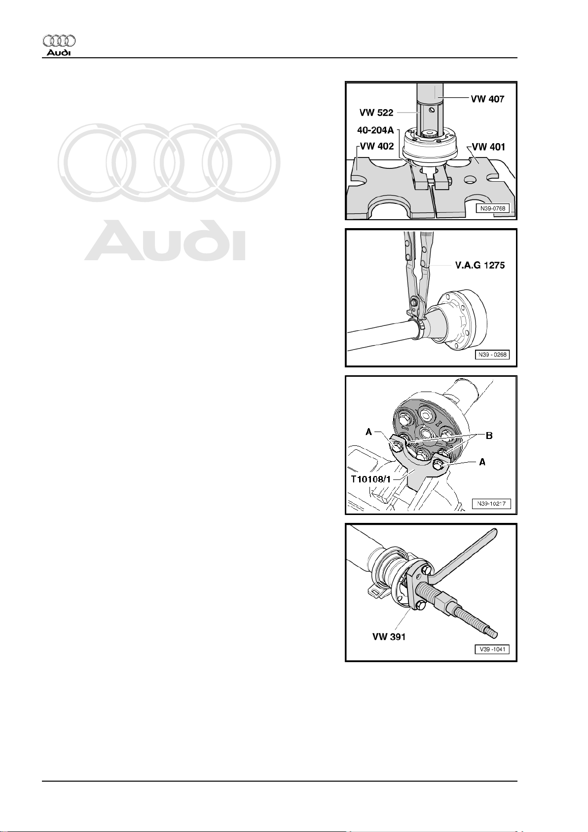
Pressing on constant velocity joint
– Press on carefully.
– Tighten tensioner -V.A.G 40-204A- firmly; propshaft must not
move out of position in tensioner, as this will cause paint dam‐
age.
– If necessary, repair paint damage as follows: remove grease
residue with nitro thinner -L 001 600- . Apply 2-component
acrylic paint -ALN 769 041- with hardener -ALZ 009 001- .
Tightening clip
Refer to ⇒ Electronic parts catalogue for clip required in the event
of a repair.
Clamp rear propshaft tube into a vice using support plate T10108/1- .
– Secure support plate -T10108/1- to flexible coupling of prop‐
shaft tube.
– To do so, fit nuts -B- onto bolts -A- between support plate -
T10108/1- and flexible coupling.
A - Bolt M10 x 70 mm with nut
B - M12 nut
Pulling off flange
24 Rep. Gr.39 - Final drive - rear differential
Page 29
Protected by copyright. Copying for private or commercial purposes, in part or in whole, is not
permitted unless authorised by AUDI AG. AUDI AG does not guarantee or accept any liability
with respect to the correctness of information in this document. Copyright by AUDI AG.
Rear final drive 02D, 0AV, 0BR and 0BY - Edition 06.2009
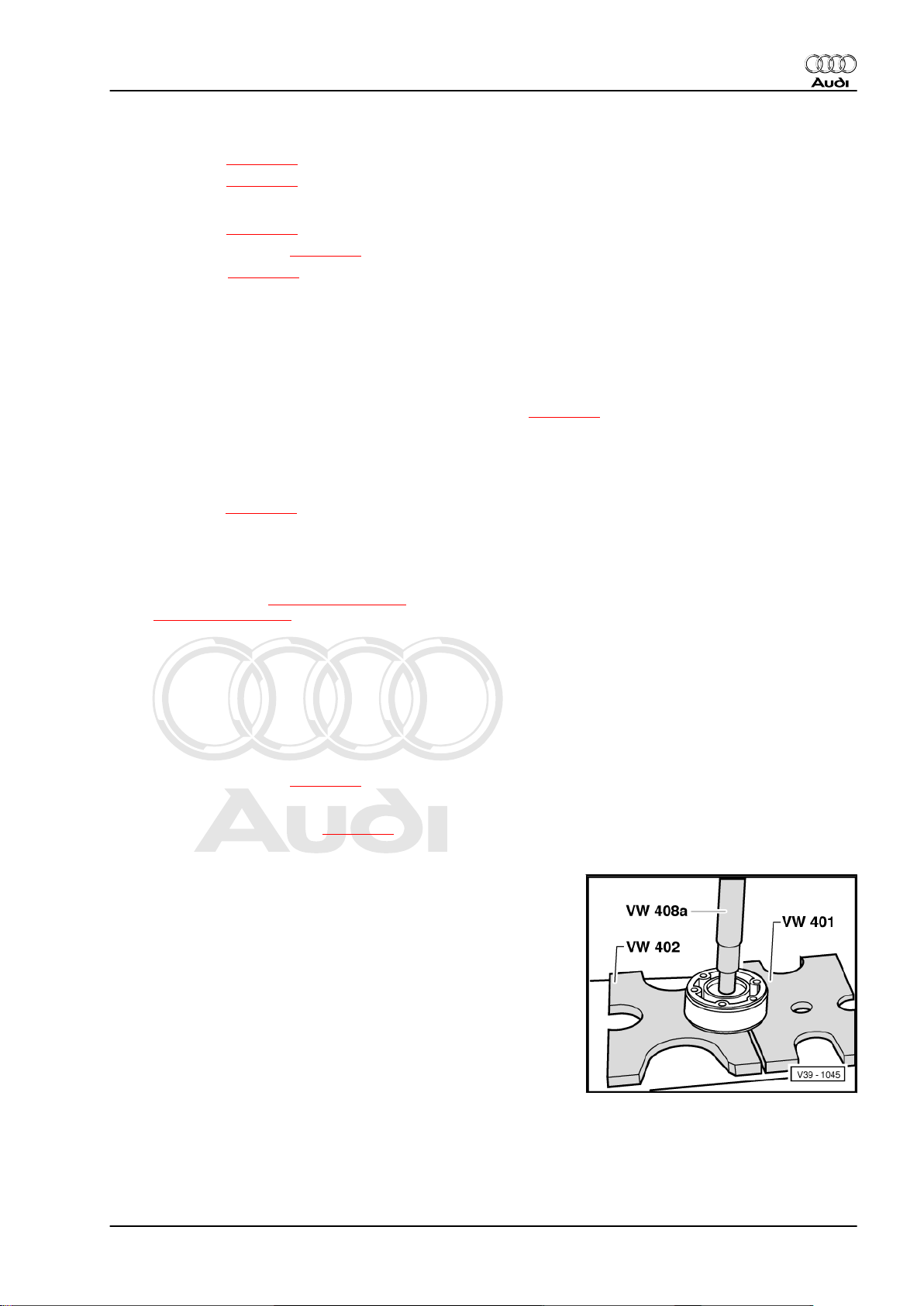
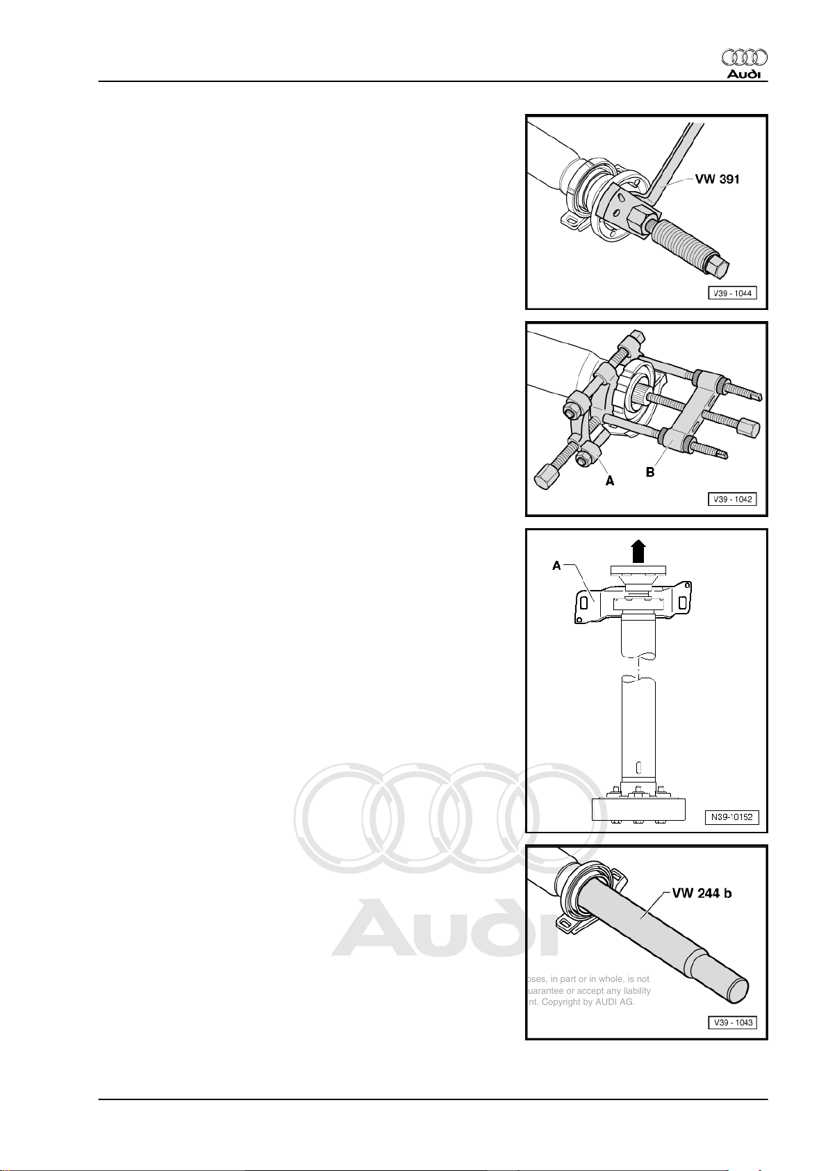
Pressing on flange
Pulling off centre bearing
– The rubber guide of the centre bearing must be cut and the
metal cover removed.
A - Splitter 12...75 mm , e.g. -Kukko 17/1-
B - Puller , e.g. -Kukko 18/0-
– Tighten splitter -A- with straight side of jaws behind centre
bearing.
– Then apply two-arm puller -B- to splitter .
– Pull centre bearing off propshaft tube.
Audi A3 2004 ➤ , Audi TT 2007 ➤
Installation position of centre bearing
The longer shoulder -A- points to left -arrow- (as seen in direction
of travel).
Driving on centre bearing
– Drive on centre bearing until limit stop.
1. Exploded view – propshaft with detachable centre bearing (up to 05.07) 25
Page 30
Protected by copyright. Copying for private or commercial purposes, in part or in whole, is not
permitted unless authorised by AUDI AG. AUDI AG does not guarantee or accept any liability
with respect to the correctness of information in this document. Copyright by AUDI AG.
Audi A3 2004 ➤ , Audi TT 2007 ➤
Rear final drive 02D, 0AV, 0BR and 0BY - Edition 06.2009
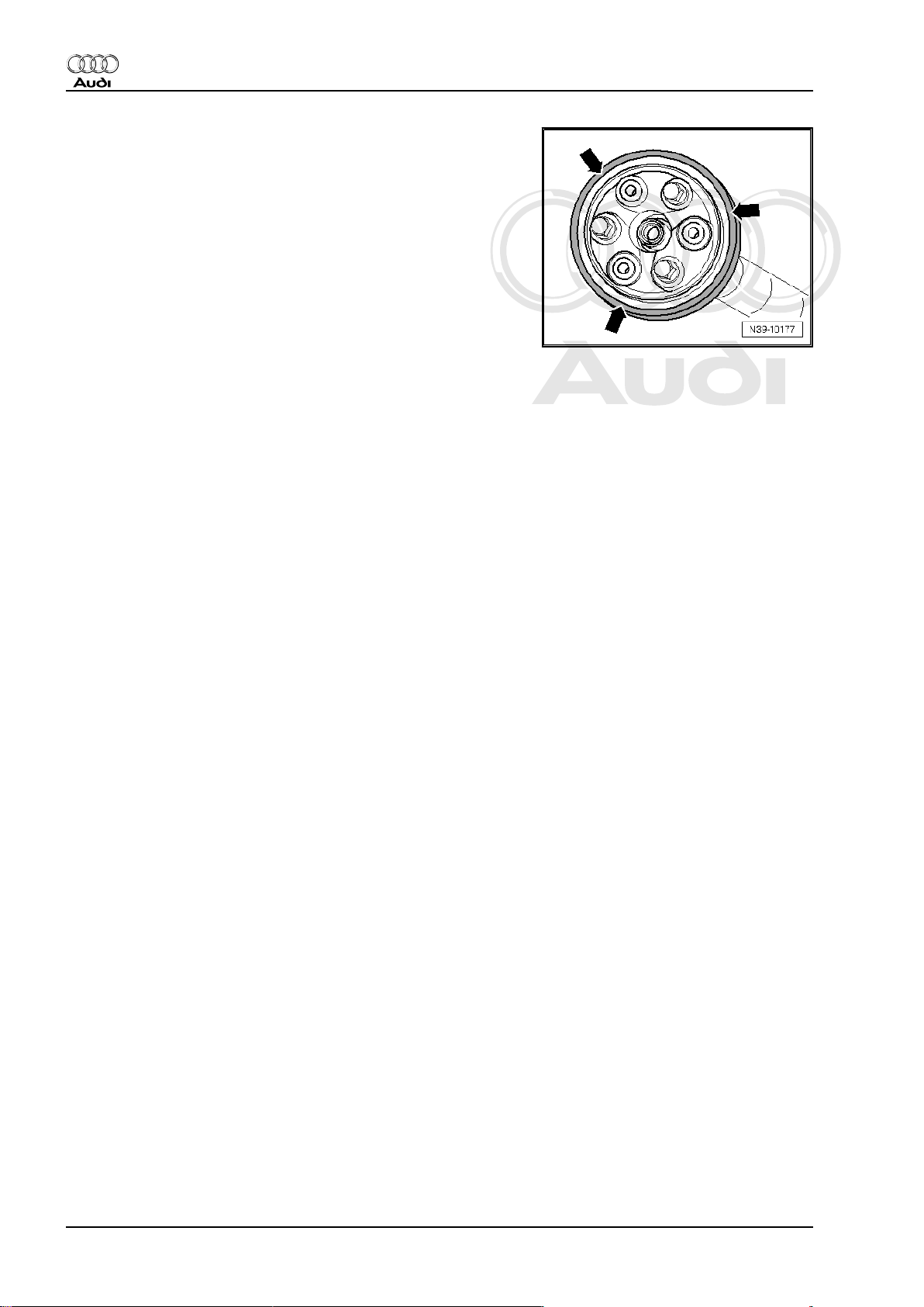
Installation position of flexible coupling with vibration damper
The shoulder on the outer circumference -arrows- must point
away from the propshaft tube.
26 Rep. Gr.39 - Final drive - rear differential
Page 31

Protected by copyright. Copying for private or commercial purposes, in part or in whole, is not
permitted unless authorised by AUDI AG. AUDI AG does not guarantee or accept any liability
with respect to the correctness of information in this document. Copyright by AUDI AG.
Rear final drive 02D, 0AV, 0BR and 0BY - Edition 06.2009
2 Removing propshaft with detachable
centre bearing (up to 05.07)
Special tools and workshop equipment required
♦ Engine/gearbox jack -V.A.G 1383 A- with universal support -
V.A.G 1359/2-
Removing
Audi A3 2004 ➤ , Audi TT 2007 ➤
Note
♦
Repairs on the propshaft should be carried out on a two pillar
hoist.
♦
Before removing, mark the positions of all parts in relation to
each other. Reinstall in the same position to avoid excessive
imbalance, resulting in bearing damage and rumbling noise.
♦
Do not bend propshaft; only store and transport fully extended.
Audi A3
– Remove noise insulation -arrows-.
Audi TT
– Remove centre noise insulation -fasteners 1 ... 4-.
2. Removing propshaft with detachable centre bearing (up to 05.07) 27
Page 32

Protected by copyright. Copying for private or commercial purposes, in part or in whole, is not
permitted unless authorised by AUDI AG. AUDI AG does not guarantee or accept any liability
with respect to the correctness of information in this document. Copyright by AUDI AG.
Audi A3 2004 ➤ , Audi TT 2007 ➤
Rear final drive 02D, 0AV, 0BR and 0BY - Edition 06.2009
Vehicles with 4-cylinder engine:
– If fitted, remove cross member on underbody -arrows-.
– Disconnect exhaust system at clamp -1-.
– Tie up front exhaust pipe on underbody.
Caution
The flexible joints in the exhaust system can be damaged.
♦ The flexible joints in the front exhaust pipe must not be
bent further than 10°.
– Remove rear section of exhaust system ⇒ Rep. Gr. 26 .
Vehicles with 6-cylinder engine:
– Remove complete exhaust system ⇒ Rep. Gr. 26 .
Continued for all vehicles:
– Support propshaft with gearbox jack -V.A.G 1383 A- (use
wooden wedge -A- as an aid).
– Then unbolt heat shield -arrows-.
– Fit centre bearing again -arrows- after removing heat shield.
– Unbolt propshaft with flexible coupling from bevel box.
28 Rep. Gr.39 - Final drive - rear differential
Page 33

Protected by copyright. Copying for private or commercial purposes, in part or in whole, is not
permitted unless authorised by AUDI AG. AUDI AG does not guarantee or accept any liability
with respect to the correctness of information in this document. Copyright by AUDI AG.
Rear final drive 02D, 0AV, 0BR and 0BY - Edition 06.2009
– Unscrew bolts -1 ... 3- and remove pendulum support.
– Check whether there are factory markings on the constant ve‐
locity joint/propshaft -arrow A- and -arrow B-. If not, please
apply colour markings.
Audi A3 2004 ➤ , Audi TT 2007 ➤
– Disconnect front propshaft tube from rear propshaft tube
-arrows-.
– Push front propshaft tube towards the front and swivel out from
flange of rear propshaft tube.
Note
Take care when swivelling out that the front propshaft tube is
pushed downwards as little as possible.
– Carefully detach front propshaft tube from centring pin on bev‐
el box.
Note
♦
The seal -arrow- in the flange of the propshaft must not be
damaged.
♦
Pull off propshaft horizontally from guide pin.
– Swivel front propshaft tube downwards and remove.
2. Removing propshaft with detachable centre bearing (up to 05.07) 29
Page 34

Protected by copyright. Copying for private or commercial purposes, in part or in whole, is not
permitted unless authorised by AUDI AG. AUDI AG does not guarantee or accept any liability
with respect to the correctness of information in this document. Copyright by AUDI AG.
Audi A3 2004 ➤ , Audi TT 2007 ➤
Rear final drive 02D, 0AV, 0BR and 0BY - Edition 06.2009
– Check whether there is a factory marking (coloured dot) on the
flexible coupling and on the flange for the propshaft on the rear
final drive -arrows-.
– If not, mark position of flexible coupling and flange for prop‐
shaft on rear final drive in relation to each other -arrows-.
– Unbolt rear propshaft with flexible coupling and vibration
damper from rear final drive -arrows-.
– Unbolt centre bearing for propshaft from vehicle -arrows-.
– Carefully pull rear propshaft tube from centring pin.
Note
♦
Do not tilt propshaft when removing; pull off centring pin hori‐
zontally. Make sure that the seal in the centring sleeve
-arrow- does not become damaged.
♦
The flexible coupling and vibration damper cannot be separa‐
ted from each other.
2.1 Installing propshaft with detachable centre bearing (up to 05.07)
Installation is carried out in reverse sequence; note the following:
30 Rep. Gr.39 - Final drive - rear differential
Page 35

Protected by copyright. Copying for private or commercial purposes, in part or in whole, is not
permitted unless authorised by AUDI AG. AUDI AG does not guarantee or accept any liability
with respect to the correctness of information in this document. Copyright by AUDI AG.
Rear final drive 02D, 0AV, 0BR and 0BY - Edition 06.2009
Note
♦
All parts of the propshaft marked in relation to each other must
be reinstalled in the same position.
♦
The seals -arrow- in flanges of the propshaft must not be dam‐
aged when removing and installing. If seals are damaged, the
propshaft must be renewed.
♦
Push propshaft horizontally onto the appropriate guide pin.
Installation position:
♦ Three projecting sleeves on the gearbox flange / rear final
drive flange and propshaft flange engage in mounting holes of
flexible coupling.
– Attach propshaft to rear final drive so that the markings
-arrows- align.
Audi A3 2004 ➤ , Audi TT 2007 ➤
Take note of the correct fitting locations for the various flange
bolts.
Flange bolt with Fitting location
small collar -arrow A- Propshaft to front final drive -A-.
Tightening torque
⇒ Item 4 (page 22)
large collar -arrow B- Propshaft to rear final drive -B-.
Tightening torque
⇒ Item 22 (page 23)
Make sure that the markings on the constant velocity joint/prop‐
shaft -arrow A- and -arrow B- are in line.
2. Removing propshaft with detachable centre bearing (up to 05.07) 31
Page 36

Protected by copyright. Copying for private or commercial purposes, in part or in whole, is not
permitted unless authorised by AUDI AG. AUDI AG does not guarantee or accept any liability
with respect to the correctness of information in this document. Copyright by AUDI AG.
Audi A3 2004 ➤ , Audi TT 2007 ➤
Rear final drive 02D, 0AV, 0BR and 0BY - Edition 06.2009
– Secure front propshaft tube to rear propshaft tube -arrows-.
Tightening torque ⇒ Item 7 (page 22)
Stress-free installation of centre bearing:
• Make sure that all propshaft bolts have been tightened.
– Position the centre bearing in its elongated holes so that the
propshaft and centre bearing are not under stress.
– Tighten bolts with washers -1-. Make sure the bolts with wash‐
ers -1- are within the four centring tabs on heat shield -2-.
Tightening torque ⇒ Item 19 (page 23)
– First secure pendulum support to gearbox -arrows B and C-,
then on subframe -arrow A-.
Component
Pendulum support to: Gearbox
Nm
40 Nm + 90°
1)
-arrows B and C-
1)
Renew bolts
Subframe -arrow A-
100 Nm + 90°
1)
– Install exhaust system and perform stress-free alignment ⇒
Rep. Gr. 26 .
– If fitted, install cross member on underbody -arrows- ⇒ Rep.
Gr. 26 .
– Install noise insulation ⇒ Rep. Gr. 66 .
32 Rep. Gr.39 - Final drive - rear differential
Page 37

Protected by copyright. Copying for private or commercial purposes, in part or in whole, is not
permitted unless authorised by AUDI AG. AUDI AG does not guarantee or accept any liability
with respect to the correctness of information in this document. Copyright by AUDI AG.
Rear final drive 02D, 0AV, 0BR and 0BY - Edition 06.2009
Note
♦
If droning noises occur during driving, note the following:
♦
Remove balancing nut and balancing washer -arrows-.
♦
Then, if necessary, unbolt propshaft with flexible coupling from
flange for propshaft on rear final drive, rotate one hole further
and screw in again.
♦
If the droning noises can still be heard, the propshaft must
again be rotated and screwed back on.
Audi A3 2004 ➤ , Audi TT 2007 ➤
2. Removing propshaft with detachable centre bearing (up to 05.07) 33
Page 38

Protected by copyright. Copying for private or commercial purposes, in part or in whole, is not
permitted unless authorised by AUDI AG. AUDI AG does not guarantee or accept any liability
with respect to the correctness of information in this document. Copyright by AUDI AG.
Audi A3 2004 ➤ , Audi TT 2007 ➤
Rear final drive 02D, 0AV, 0BR and 0BY - Edition 06.2009
3 Exploded view – propshaft with non-
detachable centre bearing (from
05.07 onwards)
The propshaft with non-detachable centre bearing was intro‐
duced as follows:
♦ Audi TT (not TT RS) from vehicle identification number
8J-8-011 001 ▸
♦ Audi A3 from model year 2008 onwards, vehicle identification
number 8P-8-000 001▸
Note
♦
No repairs can be performed on the propshaft.
♦
The front propshaft tube cannot be separated from the rear
propshaft tube.
1 - Gearbox with bevel box
2 - Bolt
❑ 50 Nm + 90°
❑ Secures front flexible
coupling to propshaft
❑ Always renew
3 - Flexible coupling (front)
❑ Installation position:
open side of heat shield
points towards gearbox
4 - Bolt
❑ 60 Nm
❑ Secures flexible cou‐
pling to bevel box
5 - Propshaft
❑ Cannot be separated at
centre joint -arrow-
❑ Removing and installing
⇒ page 35
6 - Bolt
❑ 25 Nm
7 - Centre bearing
❑ Align so that compo‐
nents are free of stress
8 - Bolt
❑ 50 Nm + 90°
❑ Secures rear flexible
coupling to propshaft
❑ Always renew
9 - Bolt
❑ 60 Nm
❑ Secures flexible coupling to final drive
34 Rep. Gr.39 - Final drive - rear differential
Page 39

Protected by copyright. Copying for private or commercial purposes, in part or in whole, is not
permitted unless authorised by AUDI AG. AUDI AG does not guarantee or accept any liability
with respect to the correctness of information in this document. Copyright by AUDI AG.
Rear final drive 02D, 0AV, 0BR and 0BY - Edition 06.2009
10 - Flexible coupling with vibration damper
❑ Heat shield faces towards propshaft
11 - Rear final drive
❑ Removing and installing ⇒ page 96
3.1 Removing propshaft with non-detacha‐
ble centre bearing (from 05.07 onwards)
Special tools and workshop equipment required
♦ Torque wrench -V.A.G 1332-
Audi A3 2004 ➤ , Audi TT 2007 ➤
♦ Engine and gearbox jack -V.A.G 1383 A-
Counterhold tool -T10172- with adapters -T10172/5-
Removing
Note
♦
Repairs on the propshaft should preferably be carried out on
a two-pillar hoist.
♦
Before removing, mark the positions of all parts in relation to
each other. Reinstall in the same position to avoid excessive
imbalance, resulting in bearing damage and rumbling noise.
♦
Do not bend propshaft; only store and transport fully extended.
♦
Always support the propshaft during removal; it must not be
allowed to “hang down” from one of the joints.
♦
Always keep the propshaft horizontal while pulling it off or fit‐
ting it on the joint flange.
3. Exploded view – propshaft with non-detachable centre bearing (from 05.07 onwards) 35
Page 40

Protected by copyright. Copying for private or commercial purposes, in part or in whole, is not
permitted unless authorised by AUDI AG. AUDI AG does not guarantee or accept any liability
with respect to the correctness of information in this document. Copyright by AUDI AG.
Audi A3 2004 ➤ , Audi TT 2007 ➤
Rear final drive 02D, 0AV, 0BR and 0BY - Edition 06.2009
Audi A3
– Remove noise insulation -arrows-.
Audi TT
– Remove centre noise insulation -fasteners 1 ... 4-.
Audi TTS
– Remove front noise insulation -1- and -2- ⇒ Rep. Gr. 66 .
Vehicles with 4-cylinder engine:
– Unbolt bracket for exhaust system -arrows-.
TT Roadster with 4-cylinder engine:
36 Rep. Gr.39 - Final drive - rear differential
Page 41

Protected by copyright. Copying for private or commercial purposes, in part or in whole, is not
permitted unless authorised by AUDI AG. AUDI AG does not guarantee or accept any liability
with respect to the correctness of information in this document. Copyright by AUDI AG.
Rear final drive 02D, 0AV, 0BR and 0BY - Edition 06.2009
– Unscrew bolts -arrows- and detach cross piece.
All vehicles with 4-cylinder engine:
– If fitted, remove cross member on underbody -arrows-.
Audi A3 2004 ➤ , Audi TT 2007 ➤
Caution
The flexible joints in the exhaust system can be damaged.
♦ The flexible joints in the front exhaust pipe must not be
bent further than 10°.
– Disconnect exhaust system at clamp -arrows-.
– Tie up front exhaust pipe on underbody.
– Remove rear section of exhaust system ⇒ Rep. Gr. 26 .
Vehicles with 6-cylinder engine:
– Remove complete exhaust system ⇒ Rep. Gr. 26 .
Continued for all vehicles:
– When loosening and tightening propshaft bolts, counterhold at
rear final drive using counterhold tool -T10172- and adapters
-T10172/5- .
3. Exploded view – propshaft with non-detachable centre bearing (from 05.07 onwards) 37
Page 42

Protected by copyright. Copying for private or commercial purposes, in part or in whole, is not
permitted unless authorised by AUDI AG. AUDI AG does not guarantee or accept any liability
with respect to the correctness of information in this document. Copyright by AUDI AG.
Audi A3 2004 ➤ , Audi TT 2007 ➤
Rear final drive 02D, 0AV, 0BR and 0BY - Edition 06.2009
– Unbolt propshaft from bevel box -arrows-.
– Remove bolts -1- and -2- for pendulum support.
– Push engine/gearbox assembly forwards and secure in posi‐
tion with a suitable block of wood -A-.
– During this step, carefully detach propshaft tube from centring
pin on bevel box.
Note
♦
The seal -arrow- in the flange of the propshaft must not be
damaged.
♦
Pull off propshaft horizontally from guide pin.
38 Rep. Gr.39 - Final drive - rear differential
Page 43

Protected by copyright. Copying for private or commercial purposes, in part or in whole, is not
permitted unless authorised by AUDI AG. AUDI AG does not guarantee or accept any liability
with respect to the correctness of information in this document. Copyright by AUDI AG.
Rear final drive 02D, 0AV, 0BR and 0BY - Edition 06.2009
– Support rear section of propshaft using engine and gearbox
jack -V.A.G 1383 A- .
A - Wooden block
– Secure propshaft against falling using belt from universal
gearbox support -V.A.G 1359/2- .
– Unscrew bolts securing centre bearing and heat shield
-arrows-.
– Detach heat shield.
– Check whether there is a factory marking (coloured dot) on the
flexible coupling and on the flange for the propshaft on the rear
final drive -arrows-.
– If not, mark position of flexible coupling and flange for prop‐
shaft on rear final drive in relation to each other -arrows-.
Audi A3 2004 ➤ , Audi TT 2007 ➤
– Remove bolts -arrows- securing propshaft to rear final drive.
– Pull propshaft off rear final drive and lay it on engine and gear‐
box jack -V.A.G 1383 A- .
3. Exploded view – propshaft with non-detachable centre bearing (from 05.07 onwards) 39
Page 44

Protected by copyright. Copying for private or commercial purposes, in part or in whole, is not
permitted unless authorised by AUDI AG. AUDI AG does not guarantee or accept any liability
with respect to the correctness of information in this document. Copyright by AUDI AG.
Audi A3 2004 ➤ , Audi TT 2007 ➤
Rear final drive 02D, 0AV, 0BR and 0BY - Edition 06.2009
– Always make sure that you do not damage the bush -arrow-
when pulling off and refitting the propshaft.
Note
Do not tilt propshaft when removing; pull off centring pin horizon‐
tally. Make sure that the seal in the centring sleeve -arrow- does
not become damaged.
WARNING
To avoid damaging the protective sleeve in the centre bearing,
keep the propshaft as straight as possible during removal, in‐
stallation and storage.
Note
A second mechanic is required for the next steps when removing
the propshaft.
– Take out the propshaft towards the rear, keeping it as straight
as possible.
3.2 Installing propshaft with non-detachable centre bearing (from 05.07 onwards)
Installation is carried out in reverse sequence; note the following:
– Install all parts in the same relative positions, as marked before
removal.
– Attach propshaft to rear final drive so that the markings
-arrows- align.
– Tighten bolts securing propshaft. Tightening torques
⇒ Item 4 (page 34) and ⇒ Item 9 (page 34) .
Stress-free installation of centre bearing:
• Make sure that all propshaft bolts have been tightened.
– Position the centre bearing in its elongated holes so that the
propshaft and centre bearing are not under stress.
– Tighten bolts with washers -1-. Make sure the bolts with wash‐
ers -1- are within the centring tabs on heat shield -2-. Tight‐
ening torque ⇒ Item 6 (page 34)
40 Rep. Gr.39 - Final drive - rear differential
Page 45

Protected by copyright. Copying for private or commercial purposes, in part or in whole, is not
permitted unless authorised by AUDI AG. AUDI AG does not guarantee or accept any liability
with respect to the correctness of information in this document. Copyright by AUDI AG.
Rear final drive 02D, 0AV, 0BR and 0BY - Edition 06.2009
– Secure pendulum support with new bolts. Tightening torques
⇒ Running gear; Rep. Gr. 40 .
Audi A3 2004 ➤ , Audi TT 2007 ➤
Component
Pendulum support to: Gearbox -1-
1)
Renew bolts
Gearbox -2-
Nm
40 Nm + 90°
40 Nm + 90°
1)
1)
– Install exhaust system ⇒ Rep. Gr. 26 .
– If fitted, install cross member on underbody -arrows- ⇒ Rep.
Gr. 26 .
– Install noise insulation ⇒ Rep. Gr. 66 .
3. Exploded view – propshaft with non-detachable centre bearing (from 05.07 onwards) 41
Page 46

Protected by copyright. Copying for private or commercial purposes, in part or in whole, is not
permitted unless authorised by AUDI AG. AUDI AG does not guarantee or accept any liability
with respect to the correctness of information in this document. Copyright by AUDI AG.
Audi A3 2004 ➤ , Audi TT 2007 ➤
Rear final drive 02D, 0AV, 0BR and 0BY - Edition 06.2009
4 Exploded view - propshaft (Audi TT
RS)
Note
No repairs can be performed on the propshaft.
1 - Gearbox with bevel box
2 - Bolt
❑ 60 Nm
❑ Secures propshaft to
bevel box
3 - Propshaft
❑ Cannot be separated at
centre joint -arrow-
❑ Removing and installing
⇒ page 35
4 - Bolt
❑ 25 Nm
5 - Centre bearing
❑ Align so that compo‐
nents are free of stress
6 - Bolt
❑ 50 Nm + 90°
❑ Secures rear flexible
coupling to propshaft
❑ Always renew
7 - Bolt
❑ 60 Nm
❑ Secures flexible cou‐
pling to final drive
8 - Flexible coupling with vibra‐
tion damper
❑ Heat shield faces to‐
wards propshaft
9 - Rear final drive
❑ Removing and installing
⇒ page 103
4.1 Removing and installing propshaft (Audi TT RS)
Special tools and workshop equipment required
42 Rep. Gr.39 - Final drive - rear differential
Page 47

Protected by copyright. Copying for private or commercial purposes, in part or in whole, is not
permitted unless authorised by AUDI AG. AUDI AG does not guarantee or accept any liability
with respect to the correctness of information in this document. Copyright by AUDI AG.
Rear final drive 02D, 0AV, 0BR and 0BY - Edition 06.2009
♦ Engine and gearbox jack -V.A.G 1383 A-
♦ Counterhold tool -T10172- with adapters -T10172/5-
Audi A3 2004 ➤ , Audi TT 2007 ➤
Removing
Note
♦
Repairs on the propshaft should preferably be carried out on
a two-pillar hoist.
♦
Before removing, mark the positions of all parts in relation to
each other. Reinstall in the same position to avoid excessive
imbalance, resulting in bearing damage and rumbling noise.
♦
Do not bend propshaft; only store and transport fully extended.
♦
Always support the propshaft during removal; it must not be
suspended from one of the joints.
♦
Always keep the propshaft horizontal while pulling it off or fit‐
ting it on the joint flange.
– Remove noise insulation panels -1- and -2- ⇒ Rep. Gr. 66 .
4. Exploded view - propshaft (Audi TT RS) 43
Page 48

Protected by copyright. Copying for private or commercial purposes, in part or in whole, is not
permitted unless authorised by AUDI AG. AUDI AG does not guarantee or accept any liability
with respect to the correctness of information in this document. Copyright by AUDI AG.
Audi A3 2004 ➤ , Audi TT 2007 ➤
Rear final drive 02D, 0AV, 0BR and 0BY - Edition 06.2009
– Remove catalytic converters ⇒ Rep. Gr. 26 .
– Remove bolts -arrows- and detach cross piece -1-.
– Unscrew bolts -2- and detach bracket -3-.
Caution
The flexible joint in the starter catalytic converter can be dam‐
aged.
♦ The flexible joint must not be bent further than 10°.
– Remove rear section of exhaust system ⇒ Rep. Gr. 26 .
– When loosening and tightening propshaft bolts, counterhold at
rear final drive using counterhold tool -T10172- and adapters
-T10172/5- .
– Remove bolts -2, 3- for pendulum support.
Note
-Item 1- can be disregarded.
44 Rep. Gr.39 - Final drive - rear differential
Page 49

Protected by copyright. Copying for private or commercial purposes, in part or in whole, is not
permitted unless authorised by AUDI AG. AUDI AG does not guarantee or accept any liability
with respect to the correctness of information in this document. Copyright by AUDI AG.
Rear final drive 02D, 0AV, 0BR and 0BY - Edition 06.2009
– Check whether there is a factory marking (paint dot) on the
flexible coupling and on the flange for the propshaft on the rear
final drive -arrows-.
– If there is no marking, mark position of flexible coupling relative
to flange for propshaft on rear final drive.
– Remove bolts -arrows- securing propshaft to rear final drive,
counterholding with counterhold tool -T10172- .
Audi A3 2004 ➤ , Audi TT 2007 ➤
– Remove bolts -arrows- securing centre bearing and heat
shield, detach heat shield.
Note
-Item A- and -V.A.G 1383 A- can be disregarded.
4. Exploded view - propshaft (Audi TT RS) 45
Page 50

Protected by copyright. Copying for private or commercial purposes, in part or in whole, is not
permitted unless authorised by AUDI AG. AUDI AG does not guarantee or accept any liability
with respect to the correctness of information in this document. Copyright by AUDI AG.
Audi A3 2004 ➤ , Audi TT 2007 ➤
Rear final drive 02D, 0AV, 0BR and 0BY - Edition 06.2009
Note
A 2nd mechanic is required for the next steps when removing the
propshaft.
Caution
Risk of damage to oil seal -arrow- in propshaft flange.
♦ The propshaft must be pulled away from the guide pin
horizontally.
Note
If seal is damaged propshaft must be renewed.
– First pull propshaft tube off centring pin on rear final drive, then
pull carefully off centring pin on bevel box.
Caution
Risk of damage to protective sleeve in centre propshaft bear‐
ing.
♦ The propshaft should be kept as straight as possible dur‐
ing removal and installation and when it is stored.
Installing
Installation is carried out in reverse sequence; note the following:
• Tightening torques ⇒ page 42
Note
Install all parts in the same relative positions, as marked before
removal.
– Attach propshaft to rear final drive so that the markings
-arrows- align.
46 Rep. Gr.39 - Final drive - rear differential
Page 51

Protected by copyright. Copying for private or commercial purposes, in part or in whole, is not
permitted unless authorised by AUDI AG. AUDI AG does not guarantee or accept any liability
with respect to the correctness of information in this document. Copyright by AUDI AG.
Rear final drive 02D, 0AV, 0BR and 0BY - Edition 06.2009
– Fit bolts -1- for centre bearing, but do not yet tighten.
– Tighten bolts securing propshaft flexible couplings to bevel
box and rear final drive.
– Align centre bearing within elongated holes so that neither
propshaft nor centre bearing are under stress.
– Tighten bolts -1-.
• The bolts must be located inside the centring tabs on the heat
shield.
– Install pendulum support ⇒ Rep. Gr. 34
– Install catalytic converters and cross piece ⇒ Rep. Gr. 26 .
– Install noise insulation ⇒ Rep. Gr. 66 .
Audi A3 2004 ➤ , Audi TT 2007 ➤
4. Exploded view - propshaft (Audi TT RS) 47
Page 52

Protected by copyright. Copying for private or commercial purposes, in part or in whole, is not
permitted unless authorised by AUDI AG. AUDI AG does not guarantee or accept any liability
with respect to the correctness of information in this document. Copyright by AUDI AG.
Audi A3 2004 ➤ , Audi TT 2007 ➤
Rear final drive 02D, 0AV, 0BR and 0BY - Edition 06.2009
5 Removing and installing flexible coupling (rear)
Special tools and workshop
equipment required
♦ Torque wrench -V.A.G
1331-
♦ Torque wrench -V.A.G
1332-
♦ Engine and gearbox jack -
V.A.G 1383 A- with univer‐
sal gearbox support V.A.G 1359/2-
Special tools and workshop equipment required
♦ Counterhold tool -T10172- with adapters -T10172/5-
48 Rep. Gr.39 - Final drive - rear differential
Page 53

Protected by copyright. Copying for private or commercial purposes, in part or in whole, is not
permitted unless authorised by AUDI AG. AUDI AG does not guarantee or accept any liability
with respect to the correctness of information in this document. Copyright by AUDI AG.
Rear final drive 02D, 0AV, 0BR and 0BY - Edition 06.2009
Removing
Note
♦
Repairs on the propshaft should be carried out on a two pillar
hoist.
♦
Before removing, mark the positions of all parts in relation to
each other. Reinstall in the same position to avoid excessive
imbalance, resulting in bearing damage and rumbling noise.
♦
Do not bend propshaft; only store and transport fully extended.
– If fitted, remove cross member on underbody -arrows-.
Caution
The flexible joints in the exhaust system can be damaged.
♦ The flexible joints in the front exhaust pipe must not be
bent further than 10°.
Audi A3 2004 ➤ , Audi TT 2007 ➤
– Disconnect exhaust system at clamp -1-.
– Tie up front exhaust pipe on underbody.
– Remove rear section of exhaust system ⇒ Rep. Gr. 26 .
– Loosen bolts -arrows- on centre bearing of propshaft approx.
2 turns.
– Take up weight of propshaft at rear propshaft tube using en‐
gine and gearbox jack -V.A.G 1383 A- .
A - Wooden block
– Secure propshaft against falling using belt from universal
gearbox support -V.A.G 1359/2- .
– Check whether there is a factory marking (coloured dot) on the
flexible coupling and on the flange for the propshaft on the rear
final drive -arrows-.
– If not, mark position of flexible coupling and flange for prop‐
shaft on rear final drive in relation to each other -arrows-.
5. Removing and installing flexible coupling (rear) 49
Page 54

Protected by copyright. Copying for private or commercial purposes, in part or in whole, is not
permitted unless authorised by AUDI AG. AUDI AG does not guarantee or accept any liability
with respect to the correctness of information in this document. Copyright by AUDI AG.
Audi A3 2004 ➤ , Audi TT 2007 ➤
Rear final drive 02D, 0AV, 0BR and 0BY - Edition 06.2009
– When loosening and tightening propshaft bolts, counterhold at
rear final drive using counterhold tool -T10172- and adapters
-T10172/5- .
– Unbolt rear propshaft tube with flexible coupling and vibration
damper from final drive -arrows-.
– Carefully detach rear propshaft tube from centring pin of prop‐
shaft flange on rear final drive.
Note
♦
Do not tilt propshaft when removing; pull off centring pin hori‐
zontally. Make sure that the seal in the centring sleeve
-arrow- does not become damaged.
♦
The flexible coupling and vibration damper cannot be separa‐
ted from each other.
– Mark position of flexible coupling (rear) and flange of rear
propshaft tube in relation to each other.
– Unbolt flexible coupling from propshaft tube -arrows-.
50 Rep. Gr.39 - Final drive - rear differential
Page 55

Protected by copyright. Copying for private or commercial purposes, in part or in whole, is not
permitted unless authorised by AUDI AG. AUDI AG does not guarantee or accept any liability
with respect to the correctness of information in this document. Copyright by AUDI AG.
Rear final drive 02D, 0AV, 0BR and 0BY - Edition 06.2009
Installing
Installation is carried out in reverse sequence; note the following:
Note
♦
The seals in flanges of the propshaft -arrow- must not be dam‐
aged when removing and installing.
♦
Renew propshaft if damaged.
♦
Do not tilt rear propshaft tube; push on horizontally onto cen‐
tring pin.
♦
All parts of the propshaft marked in relation to each other must
be reinstalled in the same position.
Installation position of flexible coupling with vibration damper:
♦ The shoulder on the outer circumference -arrows- must point
away from the propshaft tube.
♦ Three projecting sleeves on the flange for propshaft on rear
final drive and propshaft flange engage in mounting holes of
flexible coupling.
Audi A3 2004 ➤ , Audi TT 2007 ➤
– Secure flexible coupling to propshaft tube -arrows-. Tightening
torque ⇒ Item 25 (page 23)
– Attach propshaft to rear final drive so that the markings
-arrows- align.
5. Removing and installing flexible coupling (rear) 51
Page 56

Protected by copyright. Copying for private or commercial purposes, in part or in whole, is not
permitted unless authorised by AUDI AG. AUDI AG does not guarantee or accept any liability
with respect to the correctness of information in this document. Copyright by AUDI AG.
Audi A3 2004 ➤ , Audi TT 2007 ➤
Rear final drive 02D, 0AV, 0BR and 0BY - Edition 06.2009
– Secure propshaft with flexible coupling to rear final drive
-arrows-. Tightening torque ⇒ Item 22 (page 23)
Stress-free installation of centre bearing:
• Make sure that all propshaft bolts have been tightened.
– Position the centre bearing in its elongated holes so that the
propshaft and centre bearing are not under stress.
– Tighten bolts with washers -1-. Make sure the bolts with wash‐
ers -1- are within the four centring tabs on heat shield -2-.
Tightening torque ⇒ Item 19 (page 23)
– Install exhaust system and perform stress-free alignment ⇒
Rep. Gr. 26 .
– If fitted, install cross member on underbody -arrows- ⇒ Rep.
Gr. 26 .
Note
♦
If droning noises occur during driving, note the following:
♦
Remove balancing nut and balancing washer -arrows-.
♦
Then, if necessary, unbolt propshaft with flexible coupling from
flange for propshaft on rear final drive, rotate one hole further
and screw in again.
♦
If the droning noises can still be heard, the propshaft must
again be rotated and screwed back on.
52 Rep. Gr.39 - Final drive - rear differential
Page 57

Protected by copyright. Copying for private or commercial purposes, in part or in whole, is not
permitted unless authorised by AUDI AG. AUDI AG does not guarantee or accept any liability
with respect to the correctness of information in this document. Copyright by AUDI AG.
Rear final drive 02D, 0AV, 0BR and 0BY - Edition 06.2009
6 Connecting vehicle diagnostic, test‐
ing and information system -VAS
5051B- and checking system
Special tools and workshop equipment required
♦ Vehicle diagnostic, testing and information system -VAS
5051B- or vehicle diagnosis and service information system VAS 5052-
♦ Diagnostic cable, 5 m -VAS 5051B/1- or diagnostic cable, 3 m
-VAS 5051B/2-
Audi A3 2004 ➤ , Audi TT 2007 ➤
WARNING
To avoid any risk of accident, observe the
⇒ “6 Safety precautions”, page 16 when road-testing the vehi‐
cle and using test equipment.
– With the ignition switched off, connect the vehicle diagnostic,
testing and information system -VAS 5051B- to the diagnostic
connector using diagnostic cable, 5 m -VAS 5051B/1- or -VAS
5051B/2- .
Fitting location: footwell (front left), next to bonnet release lever.
Starting “Guided fault finding”:
– Switch on ignition.
– Touch field/key “Guided fault finding” on screen.
– Select the options on the tester in this sequence:
♦ Brand
♦ Model
♦ Model year
♦ Version
♦ Engine code letters
– Confirm the data entered.
– Wait until the tester has interrogated all on-board control units
and set up a test routine.
– Work through the test routine.
6. Connecting vehicle diagnostic, testing and information system VAS 5051B and checking system 53
Page 58

Protected by copyright. Copying for private or commercial purposes, in part or in whole, is not
permitted unless authorised by AUDI AG. AUDI AG does not guarantee or accept any liability
with respect to the correctness of information in this document. Copyright by AUDI AG.
Audi A3 2004 ➤ , Audi TT 2007 ➤
Rear final drive 02D, 0AV, 0BR and 0BY - Edition 06.2009
7 Checking function of Haldex cou‐
pling, rear final drive “02D/0AV”
Note
The identification -arrow- on the underside of the final drive unit
indicates which final drive version is installed.
Example of identification markings on final drive “02D”
♦ ⇒ “7.1 Final drive02D/0AV – Checking function of open Haldex
coupling on vehicles with manual gearbox”, page 54
♦ ⇒ “7.2 Final drive02D/0AV – Checking function of closed Hal‐
dex coupling on vehicles with manual gearbox”, page 55
♦ ⇒ “7.3 Final drive02D/0AV – Checking function of open Haldex
coupling on vehicles with dual clutch gearbox”, page 56
♦ ⇒ “7.4 Final drive02D/0AV – Checking function of closed Hal‐
dex coupling on vehicles with dual clutch gearbox”,
page 56
Before servicing the Haldex coupling, the exact cause of the fail‐
ure must be determined as precisely as possible via the vehicle
diagnostic, testing and information system -VAS 5051B- in the
modes “Guided Fault Finding”, “vehicle self-diagnosis” and “test‐
ing system”.
⇒ “6 Connecting vehicle diagnostic, testing and information sys‐
tem VAS 5051B and checking system”, page 53
7.1 Final drive“02D/0AV” – Checking func‐
tion of open Haldex coupling on vehicles
with manual gearbox
Test requirements:
♦ Oil level of Haldex coupling OK
♦ Checking oil level in Haldex coupling ⇒ page 115 .
♦ Correct engine control unit and ABS control unit installed
(check coding and control unit identification number).
– Place vehicle on lifting platform.
Caution
For safety reasons it is essential that the wheels do not touch
the ground when the vehicle is on the lifting platform.
Carry out test with care to avoid damage.
– Press clutch pedal.
– Start engine.
54 Rep. Gr.39 - Final drive - rear differential
Page 59

Protected by copyright. Copying for private or commercial purposes, in part or in whole, is not
permitted unless authorised by AUDI AG. AUDI AG does not guarantee or accept any liability
with respect to the correctness of information in this document. Copyright by AUDI AG.
Rear final drive 02D, 0AV, 0BR and 0BY - Edition 06.2009
– Depress clutch pedal all the way, select 1st gear and release
clutch carefully.
All four wheels must turn.
– Apply handbrake.
The rear wheels must stop turning and the front wheels must
continue to turn.
• If the rear wheels do not turn:
The Haldex coupling is open; function is OK.
• If the rear wheels turn:
The Haldex coupling is closed. Possible cause of fault:
♦ Main pressure regulating valve sticking
♦ Mechanical fault in Haldex coupling
♦ Four-wheel drive control unit -J492- at rear final drive defective
♦ Handbrake warning switch -F9- defective
7.2 Final drive“02D/0AV” – Checking func‐
tion of closed Haldex coupling on vehi‐
cles with manual gearbox
Audi A3 2004 ➤ , Audi TT 2007 ➤
Test requirements:
♦ Oil level of Haldex coupling OK
♦ Checking oil level in Haldex coupling ⇒ page 115 .
♦ Correct engine control unit and ABS control unit installed
(check coding and control unit identification number).
– Place vehicle on lifting platform.
Caution
For safety reasons it is essential that the wheels do not touch
the ground when the vehicle is on the lifting platform.
Carry out test with care to avoid damage.
– Press clutch pedal.
– Start engine.
– Depress clutch pedal all the way and select 2nd gear.
– Apply handbrake and release clutch carefully.
The engine should now stall.
• Engine did stall:
The Haldex coupling is closed; function is OK.
• Engine did not stall:
The Haldex coupling is open. Possible cause of fault:
♦ Main pressure regulating valve sticking
♦ Mechanical fault in Haldex coupling
♦ Four-wheel drive control unit -J492- at rear final drive defective
7. Checking function of Haldex coupling, rear final drive “02D/0AV” 55
Page 60

Protected by copyright. Copying for private or commercial purposes, in part or in whole, is not
permitted unless authorised by AUDI AG. AUDI AG does not guarantee or accept any liability
with respect to the correctness of information in this document. Copyright by AUDI AG.
Audi A3 2004 ➤ , Audi TT 2007 ➤
Rear final drive 02D, 0AV, 0BR and 0BY - Edition 06.2009
7.3 Final drive“02D/0AV” – Checking func‐
tion of open Haldex coupling on vehicles
with dual clutch gearbox
Test requirements:
♦ Oil level of Haldex coupling OK
♦ Checking oil level in Haldex coupling ⇒ page 115 .
♦ Correct engine control unit and ABS control unit installed
(check coding and control unit identification number).
– Place vehicle on lifting platform.
Caution
For safety reasons it is essential that the wheels do not touch
the ground when the vehicle is on the lifting platform.
Carry out test with care to avoid damage.
– Start engine.
– Select gear D and operate accelerator pedal slightly.
All four wheels must turn.
– Apply handbrake.
The rear wheels must stop turning and the front wheels must
continue to turn.
• If the rear wheels do not turn:
The Haldex coupling is open; function is OK.
• If the rear wheels turn:
The Haldex coupling is closed. Possible cause of fault:
♦ Main pressure regulating valve sticking
♦ Mechanical fault in Haldex coupling
♦ Four-wheel drive control unit -J492- at rear final drive defective
♦ Handbrake warning switch -F9- defective
7.4 Final drive“02D/0AV” – Checking func‐
tion of closed Haldex coupling on vehi‐
cles with dual clutch gearbox
Test requirements:
♦ Oil level of Haldex coupling OK
♦ Checking oil level in Haldex coupling ⇒ page 115 .
♦ Correct engine control unit and ABS control unit installed
(check coding and control unit identification number).
– Place vehicle on lifting platform.
56 Rep. Gr.39 - Final drive - rear differential
Page 61

Protected by copyright. Copying for private or commercial purposes, in part or in whole, is not
permitted unless authorised by AUDI AG. AUDI AG does not guarantee or accept any liability
with respect to the correctness of information in this document. Copyright by AUDI AG.
Rear final drive 02D, 0AV, 0BR and 0BY - Edition 06.2009
Caution
For safety reasons it is essential that the wheels do not touch
the ground when the vehicle is on the lifting platform.
Carry out test with care to avoid damage.
– Start engine.
– Select gear D and release brake pedal.
All four wheels must turn.
– Apply handbrake.
– Depress accelerator pedal slightly.
The engine should pull noticeably against the handbrake.
• If pulling power is noticeable:
The Haldex coupling is closed; function is OK.
• If pulling power is not noticeable:
The Haldex coupling is open. Possible cause of fault:
♦ Main pressure regulating valve sticking
♦ Mechanical fault in Haldex coupling
♦ Four-wheel drive control unit -J492- at rear final drive defective
Audi A3 2004 ➤ , Audi TT 2007 ➤
7. Checking function of Haldex coupling, rear final drive “02D/0AV” 57
Page 62

Protected by copyright. Copying for private or commercial purposes, in part or in whole, is not
permitted unless authorised by AUDI AG. AUDI AG does not guarantee or accept any liability
with respect to the correctness of information in this document. Copyright by AUDI AG.
Audi A3 2004 ➤ , Audi TT 2007 ➤
Rear final drive 02D, 0AV, 0BR and 0BY - Edition 06.2009
8 Checking function of Haldex cou‐
pling, rear final drive “0BR” and “0BY”
Identification marking on rear final drive “0BR” and “0BY”
Note
♦
The identification -arrow- on the underside of the final drive
unit indicates which final drive version is installed.
♦
The Haldex coupling can checked by road-testing the vehicle
and using vehicle diagnostic, testing and information system
- VAS 5051B- .
WARNING
To avoid any risk of accident, observe the
⇒ “6 Safety precautions”, page 16 when road-testing the vehi‐
cle and using test equipment.
– Connect the vehicle diagnostic, testing and information sys‐
tem -VAS 5051B- to the diagnostic connector with the ignition
switched off.
Fitting location: footwell (front left), next to bonnet release lever.
Starting “Guided Functions”:
– Switch on ignition.
– Touch the symbol or button “Guided Functions” on the screen.
– Select the options on the tester in this sequence:
♦ Brand
♦ Model
♦ Model year
♦ Version
♦ Engine code letters
♦ Confirm the data entered.
♦ 22 - 4WD electronics
♦ 22 - Final control diagnosis
– Start final control diagnosis and follow instructions appearing
on tester.
58 Rep. Gr.39 - Final drive - rear differential
Page 63

Protected by copyright. Copying for private or commercial purposes, in part or in whole, is not
permitted unless authorised by AUDI AG. AUDI AG does not guarantee or accept any liability
with respect to the correctness of information in this document. Copyright by AUDI AG.
Audi A3 2004 ➤ , Audi TT 2007 ➤
Rear final drive 02D, 0AV, 0BR and 0BY - Edition 06.2009
9 Electrical and electronic components and fitting locations, rear final
drive “02D/0AV”
1 - Four-wheel drive control
unit -J492-
❑ Fitting location
⇒ page 60
❑ Is supplied as one unit
together with the cou‐
pling opening control
valve -N373-
❑ The pressure sensor is
also located in the con‐
trol unit
❑ Removing and installing
⇒ page 61
❑ Important signals are
transferred to fourwheel drive control unit
from the engine control
unit and the ABS with
EDL control unit -J104via data bus.
2 - Haldex coupling pump V181-
❑ Fitting location
⇒ page 60
❑ Can be checked in “Gui‐
ded fault finding”, using
vehicle diagnostic, test‐
ing and information sys‐
tem -VAS 5051B- .
❑ Removing and installing
⇒ page 78
3 - Diagnostic connector
❑ Fitting location: footwell
(front left), next to bon‐
net release lever
4 - Handbrake warning switch
-F9❑ Fitting location ⇒ page 60
❑ Can be checked in “Guided fault finding” using vehicle diagnostic, testing and information system -
VAS 5051- .
❑ Removing and installing ⇒ Rep. Gr. 46
5 - Brake light switch -F-
❑ Fitting location: ⇒ page 60
❑ Can be checked in “Guided fault finding”, using vehicle diagnostic, testing and information system -VAS
5051B- .
❑ Removing and installing ⇒ Rep. Gr. 46
9. Electrical and electronic components and fitting locations, rear final drive “02D/0AV” 59
Page 64

Protected by copyright. Copying for private or commercial purposes, in part or in whole, is not
permitted unless authorised by AUDI AG. AUDI AG does not guarantee or accept any liability
with respect to the correctness of information in this document. Copyright by AUDI AG.
Audi A3 2004 ➤ , Audi TT 2007 ➤
Rear final drive 02D, 0AV, 0BR and 0BY - Edition 06.2009
Four-wheel drive control unit -J492-
Fitting location: the control unit -A- is located at the front left-hand
side of the rear final drive .
Haldex coupling pump -V181-
Fitting location: the Haldex coupling pump -arrow- is located at
the front right-hand side of the rear final drive.
Brake light switch -F-
Fitting location: the brake light switch -F- is located at the pedal
cluster above the brake pedal.
Removing:
⇒ Rep. Gr. 46
Handbrake warning switch -F9-
Fitting location: switch -arrow- is located on handbrake lever.
Removing ⇒ Rep. Gr. 46
60 Rep. Gr.39 - Final drive - rear differential
Page 65

Protected by copyright. Copying for private or commercial purposes, in part or in whole, is not
permitted unless authorised by AUDI AG. AUDI AG does not guarantee or accept any liability
with respect to the correctness of information in this document. Copyright by AUDI AG.
Audi A3 2004 ➤ , Audi TT 2007 ➤
Rear final drive 02D, 0AV, 0BR and 0BY - Edition 06.2009
10 Exploded view – removing and installing four-wheel drive control unit
-J492- , rear final drive “02D/0AV”
1 - Four-wheel drive control
unit -J492-
❑ Calibrated to match
coupling opening con‐
trol valve -N373-
⇒ Item 4 (page 61)
❑ Always renew together
with valve
⇒ Item 4 (page 61)
❑ Removing and installing
⇒ page 62
2 - Bolt, 6 Nm
3 - Cover
❑ With vulcanised seal
❑ Always renew
4 - Coupling opening control
valve -N373-
❑ Calibrated to match
four-wheel drive control
unit -J492-
❑ Always renew together
with control unit
⇒ Item 1 (page 61)
5 - Seal
❑ Diameter 12 mm
❑ For coupling opening
control valve -N373-
❑ Lubricate with high-per‐
formance oil for Haldex
coupling prior to insert‐
ing
❑ Always renew
6 - Seal
❑ Diameter 11 mm
❑ For coupling opening control valve -N373❑ Lubricate with high-performance oil for Haldex coupling prior to inserting
❑ Always renew
7 - Seal
❑ In Haldex coupling housing
❑ Lubricate with high-performance oil for Haldex coupling prior to inserting
❑ Always renew
8 - Seal
❑ For pressure sensor
❑ Lubricate with high-performance oil for Haldex coupling prior to inserting
❑ Always renew
9 - Oil pressure and oil temperature sender -G437-
❑ Can be re-used when renewing control unit
❑ Removing and installing ⇒ page 62
10. Exploded view – removing and installing four-wheel drive control unit J492 , rear final drive “02D/0AV” 61
Page 66

Protected by copyright. Copying for private or commercial purposes, in part or in whole, is not
permitted unless authorised by AUDI AG. AUDI AG does not guarantee or accept any liability
with respect to the correctness of information in this document. Copyright by AUDI AG.
Audi A3 2004 ➤ , Audi TT 2007 ➤
Rear final drive 02D, 0AV, 0BR and 0BY - Edition 06.2009
10 - Dished spring
❑ When installed, the mark -arrow- must be at the top and face the pressure sensor ⇒ page 62
Installation position of dished spring
• The marking -arrow- is located on the convex side of the
dished spring -2-.
• The convex side with the marking -arrow- faces the pressure
sensor -1-.
• When installed, the marking -arrow- points to the top.
10.1 Removing and installing four-wheel
drive control unit -J492- , rear final drive
“02D/0AV”
Special tools and workshop equipment required
♦ Torque wrench -V.A.G 1331-
♦ Drip tray for workshop hoist -VAS 6208-
62 Rep. Gr.39 - Final drive - rear differential
Page 67

Protected by copyright. Copying for private or commercial purposes, in part or in whole, is not
permitted unless authorised by AUDI AG. AUDI AG does not guarantee or accept any liability
with respect to the correctness of information in this document. Copyright by AUDI AG.
Rear final drive 02D, 0AV, 0BR and 0BY - Edition 06.2009
Removing
Note
The cover -2- and the dished spring -5- are removed together
when removing the control unit -1-. The pressure sensor -4- and
the valve -3- are removed separately.
– Switch off ignition.
– Unplug connectors -1- and -2- at top of control unit.
– Position drip tray under final drive.
Audi A3 2004 ➤ , Audi TT 2007 ➤
– Remove bolts -arrows-.
Make sure that no parts drop to the ground when removing the
control unit.
– Carefully detach control unit -A-.
– Carefully take hold of coupling opening control valve -N373-
-A- at metal housing -arrow- using pliers, and pull out.
– Remove pressure sensor -B-.
10. Exploded view – removing and installing four-wheel drive control unit J492 , rear final drive “02D/0AV” 63
Page 68

Protected by copyright. Copying for private or commercial purposes, in part or in whole, is not
permitted unless authorised by AUDI AG. AUDI AG does not guarantee or accept any liability
with respect to the correctness of information in this document. Copyright by AUDI AG.
Audi A3 2004 ➤ , Audi TT 2007 ➤
Rear final drive 02D, 0AV, 0BR and 0BY - Edition 06.2009
– Remove seal for coupling opening control valve -N373-
-arrow- from housing.
Installing
Installation is carried out in the reverse order; note the following:
– Lubricate new seal for coupling opening control valve -N373-
-arrow- with high performance oil for Haldex coupling and fit
seal in housing.
– Renew O-rings -1- and -2-.
– Note different diameters:
♦ Inner diameter of O-ring -1- = 11 mm
♦ Inner diameter of O-ring -2- = 12 mm
– Renew O-ring -arrow A- on pressure sensor.
Note
When installed, the marking -arrow B- on the convex side of the
dished spring -2- points to the top and to pressure sensor -1-.
– Fit dished spring -2- with convex side first onto pressure sen‐
sor -1-.
64 Rep. Gr.39 - Final drive - rear differential
Page 69

Protected by copyright. Copying for private or commercial purposes, in part or in whole, is not
permitted unless authorised by AUDI AG. AUDI AG does not guarantee or accept any liability
with respect to the correctness of information in this document. Copyright by AUDI AG.
Rear final drive 02D, 0AV, 0BR and 0BY - Edition 06.2009
– Fit new cover -5- onto control unit -6-.
– Insert pressure sensor -4- with dished spring into new cover
-5- and press onto connector. The convex side of the dished
spring faces pressure sensor.
– Lightly lubricate new O-ring of pressure sensor -4- with high-
performance oil for Haldex coupling .
– Insert valve -1- into new cover -5- and control unit -6- and press
onto connector.
– Lightly lubricate new O-rings -2- and -3- with high-perform‐
ance oil for Haldex coupling .
– Carefully fit control unit -A- and tighten bolts -arrows- to torque
⇒ Item 2 (page 61) .
– Check oil level in Haldex coupling ⇒ page 115 .
Audi A3 2004 ➤ , Audi TT 2007 ➤
10. Exploded view – removing and installing four-wheel drive control unit J492 , rear final drive “02D/0AV” 65
Page 70

Protected by copyright. Copying for private or commercial purposes, in part or in whole, is not
permitted unless authorised by AUDI AG. AUDI AG does not guarantee or accept any liability
with respect to the correctness of information in this document. Copyright by AUDI AG.
Audi A3 2004 ➤ , Audi TT 2007 ➤
Rear final drive 02D, 0AV, 0BR and 0BY - Edition 06.2009
11 Electrical and electronic components and fitting locations, rear final
drive “0BR” and “0BY”
1 - Four-wheel drive control
unit -J492-
❑ Important signals are
transferred to fourwheel drive control unit
from the engine control
unit and the ABS with
EDL control unit -J104via data bus.
❑ Exploded view
⇒ page 67
❑ Removing and installing
⇒ page 68
2 - Coupling opening control
valve -N373-
3 - Haldex coupling pump V181-
❑ Can be checked in “Gui‐
ded fault finding”, using
vehicle diagnostic, test‐
ing and information sys‐
tem -VAS 5051B- .
❑ Removing and installing
⇒ page 78
4 - Diagnostic connector
❑ Fitting location: front
footwell (left-side)
5 - Accelerator position sender
-G79-
66 Rep. Gr.39 - Final drive - rear differential
Page 71

Protected by copyright. Copying for private or commercial purposes, in part or in whole, is not
permitted unless authorised by AUDI AG. AUDI AG does not guarantee or accept any liability
with respect to the correctness of information in this document. Copyright by AUDI AG.
Audi A3 2004 ➤ , Audi TT 2007 ➤
Rear final drive 02D, 0AV, 0BR and 0BY - Edition 06.2009
12 Exploded view – removing and instal‐
ling four-wheel drive control unit J492- , rear final drive 0BD and 0BY
For more detailed information refer to:
♦ ⇒ Self-study programme No. 414 ; 4Motion with Four-Wheel-
Coupling Generation IV
1 - Four-wheel drive control
unit -J492-
❑ Is calibrated to match
coupling opening con‐
trol valve -N373-
❑ Always renew together
with valve
❑ Removing and installing
⇒ page 68
2 - Bolt, 6 Nm
3 - Cover
❑ With vulcanised seal
❑ Will remain attached to
control unit or housing of
Haldex coupling when
control unit is removed
❑ Always renew
4 - Coupling opening control
valve -N373-
❑ Calibrated to match
four-wheel drive control
unit -J492-
❑ Always renew together
with control unit
❑ Removing and installing
⇒ page 68
5 - Seal
❑ Make sure that centring
lips are correctly seated
in groove
❑ Lubricate with high-per‐
formance oil for Haldex
coupling prior to insert‐
ing
❑ Always renew
6 - Seal
❑ Diameter 12 mm
❑ Lubricate with high-performance oil for Haldex coupling prior to inserting
❑ Always renew
7 - Seal
❑ Diameter 11 mm
❑ Lubricate with high-performance oil for Haldex coupling prior to inserting
❑ Always renew
8 - Seal
❑ Diameter 10 mm
12. Exploded view – removing and installing four-wheel drive control unit J492 , rear final drive 0BD and 0BY 67
Page 72

Protected by copyright. Copying for private or commercial purposes, in part or in whole, is not
permitted unless authorised by AUDI AG. AUDI AG does not guarantee or accept any liability
with respect to the correctness of information in this document. Copyright by AUDI AG.
Audi A3 2004 ➤ , Audi TT 2007 ➤
Rear final drive 02D, 0AV, 0BR and 0BY - Edition 06.2009
❑ Lubricate with high-performance oil for Haldex coupling prior to inserting
❑ Always renew
12.1 Removing and installing four-wheel
drive control unit -J492-
Special tools and workshop equipment required
♦ Allen key (4 mm)
♦ Torque wrench (2 ... 10 Nm) -V.A.G 1783-
♦ Drip tray for workshop hoist -VAS 6208-
– Switch off ignition.
– Unplug connectors -1- and -2- at top of control unit.
– Position drip tray under final drive.
Note
It is advisable to have a workshop trolley with tools and cleaning
cloths within easy reach so that removed parts can be put down
safely.
68 Rep. Gr.39 - Final drive - rear differential
Page 73

Protected by copyright. Copying for private or commercial purposes, in part or in whole, is not
permitted unless authorised by AUDI AG. AUDI AG does not guarantee or accept any liability
with respect to the correctness of information in this document. Copyright by AUDI AG.
Rear final drive 02D, 0AV, 0BR and 0BY - Edition 06.2009
– Remove bolts -arrows-.
– Carefully detach control unit -A-.
– If necessary, detach cover ⇒ Item 3 (page 67) from housing of
Haldex coupling, while keeping hold of valve -arrow-.
– Place a cloth over coupling opening control valve -N373-
-arrow-, take hold of valve body with pliers and pull out valve.
Installing
Installation is carried out in reverse sequence; note the following:
Audi A3 2004 ➤ , Audi TT 2007 ➤
Note
The seals for the valve have different internal diameters.
♦ -1- Internal diameter: 10 mm
♦ -2- Internal diameter: 11 mm
♦ -3- Internal diameter: 12 mm
♦ -4- Seal on valve body
– First lubricate seal -1- with Haldex oil and fit seal onto coupling
opening control valve -N373- .
– Then fit seals -2-, -3- and -4-.
– Press centring lips (4x) of seal -4- into groove.
12. Exploded view – removing and installing four-wheel drive control unit J492 , rear final drive 0BD and 0BY 69
Page 74

Protected by copyright. Copying for private or commercial purposes, in part or in whole, is not
permitted unless authorised by AUDI AG. AUDI AG does not guarantee or accept any liability
with respect to the correctness of information in this document. Copyright by AUDI AG.
Audi A3 2004 ➤ , Audi TT 2007 ➤
Rear final drive 02D, 0AV, 0BR and 0BY - Edition 06.2009
– Fit new cover -2- onto control unit -1-.
Note
The cover can only be fitted in one position.
– Insert coupling opening control valve -N373- -3- in control unit
-1-.
Note
The valve can only be fitted in one position.
– Carefully fit control unit -A- and tighten bolts -arrows- to torque
⇒ Item 2 (page 67) .
– Check oil level in Haldex coupling ⇒ page 115 .
70 Rep. Gr.39 - Final drive - rear differential
Page 75

Protected by copyright. Copying for private or commercial purposes, in part or in whole, is not
permitted unless authorised by AUDI AG. AUDI AG does not guarantee or accept any liability
with respect to the correctness of information in this document. Copyright by AUDI AG.
Audi A3 2004 ➤ , Audi TT 2007 ➤
Rear final drive 02D, 0AV, 0BR and 0BY - Edition 06.2009
13 Exploded view - removing and installing Haldex coupling
1 - Hexagon bolt, 50 Nm
❑ 4x
2 - Haldex coupling
❑ With control unit
❑ Removing and installing
⇒ page 71
❑ ⇒ “14 Exploded view –
dismantling and assem‐
bling Haldex coupling,
rear final drive 02D/0AV
”, page 75
❑ ⇒ “15 Exploded view –
dismantling and assem‐
bling Haldex coupling,
rear final drive 0BR/0BY
”, page 88
3 - O-ring
❑ Renewing ⇒ page 71
❑ Lubricate with high per‐
formance oil for Haldex
coupling prior to insert‐
ing
4 - Final drive
❑ Removing and installing
⇒ page 96
13.1 Removing and installing Haldex cou‐
pling (with final drive installed)
Special tools and workshop equipment required
♦ Torque wrench -V.A.G 1331-
13. Exploded view - removing and installing Haldex coupling 71
Page 76

Protected by copyright. Copying for private or commercial purposes, in part or in whole, is not
permitted unless authorised by AUDI AG. AUDI AG does not guarantee or accept any liability
with respect to the correctness of information in this document. Copyright by AUDI AG.
Audi A3 2004 ➤ , Audi TT 2007 ➤
Rear final drive 02D, 0AV, 0BR and 0BY - Edition 06.2009
♦ Drip tray for workshop hoist -VAS 6208-
♦ Engine/gearbox jack -V.A.G 1383 A- with universal support -
V.A.G 1359/2-
♦ Guide pins -T10093-
Removing
Caution
The flexible joints in the exhaust system can be damaged.
♦ The flexible joints in the front exhaust pipe must not be
bent further than 10°.
– Disconnect exhaust system at clamp -arrows-.
– Tie up front exhaust pipe on underbody.
– Remove rear section of exhaust system ⇒ Rep. Gr. 26 .
72 Rep. Gr.39 - Final drive - rear differential
Page 77

Protected by copyright. Copying for private or commercial purposes, in part or in whole, is not
permitted unless authorised by AUDI AG. AUDI AG does not guarantee or accept any liability
with respect to the correctness of information in this document. Copyright by AUDI AG.
Rear final drive 02D, 0AV, 0BR and 0BY - Edition 06.2009
– Remove flexible coupling (rear) ⇒ page 48 .
– Unplug connector -2- on four-wheel drive control unit -J492- .
– Position drip tray -VAS 6208- under final drive.
– Remove drain plug -A - and drain high performance oil for
Haldex coupling completely.
– Fit drain plug -A- with new seal.
Tightening torque for plug -A-: 30 Nm
Audi A3 2004 ➤ , Audi TT 2007 ➤
– Unscrew securing bolts -arrows- and remove Haldex coupling
from rear final drive.
Installing Haldex coupling
Perform installation in reverse sequence of removal. Note the fol‐
lowing:
– Remove "old" O-ring -arrow- from Haldex coupling.
– Insert new O-ring -arrow- and lubricate lightly with high-per‐
formance oil for Haldex coupling .
13. Exploded view - removing and installing Haldex coupling 73
Page 78

Protected by copyright. Copying for private or commercial purposes, in part or in whole, is not
permitted unless authorised by AUDI AG. AUDI AG does not guarantee or accept any liability
with respect to the correctness of information in this document. Copyright by AUDI AG.
Audi A3 2004 ➤ , Audi TT 2007 ➤
Rear final drive 02D, 0AV, 0BR and 0BY - Edition 06.2009
– Insert Haldex coupling -1- into rear final drive. Screw in guide
pins -T10093- for exact fitting.
– Insert Haldex coupling as far as stop (turn propshaft flange
-2-).
– Tighten bolts -arrows- to specified torque
⇒ Item 1 (page 71) .
– Plug connector -2- into four-wheel drive control unit -J492- .
– Install flexible coupling (rear) ⇒ page 48 .
– Install exhaust system and perform stress-free alignment ⇒
Rep. Gr. 26 .
– Fill up with high-performance oil for Haldex coupling and check
oil level in Haldex coupling ⇒ page 115 .
74 Rep. Gr.39 - Final drive - rear differential
Page 79

Protected by copyright. Copying for private or commercial purposes, in part or in whole, is not
permitted unless authorised by AUDI AG. AUDI AG does not guarantee or accept any liability
with respect to the correctness of information in this document. Copyright by AUDI AG.
Audi A3 2004 ➤ , Audi TT 2007 ➤
Rear final drive 02D, 0AV, 0BR and 0BY - Edition 06.2009
14 Exploded view – dismantling and assembling Haldex coupling, rear
final drive “02D/0AV”
1 - Multi-plate clutch
❑ Overview
⇒ Fig. “ Assembly of
multi-plate clutch “ ,
page 77
❑ Removing and installing
⇒ page 82
2 - Bolts
❑ 6 Nm
3 - Haldex coupling pump V181-
❑ Removing and installing
⇒ page 78
4 - O-ring
❑ Diameter 32 mm
❑ For Haldex coupling
pump -V181-
❑ Lubricate with high-per‐
formance oil for Haldex
coupling prior to insert‐
ing
❑ Always renew
5 - O-ring
❑ Diameter 30 mm
❑ For Haldex coupling
pump -V181-
❑ Lubricate with high-per‐
formance oil for Haldex
coupling prior to insert‐
ing
❑ Always renew
6 - Sealing cap
❑ 35 Nm
7 - O-ring
❑ For sealing cap
❑ Lubricate with high-performance oil for Haldex coupling prior to inserting
❑ Always renew
8 - Oil filter bracket
9 - O-ring
❑ For oil filter bracket
❑ Lubricate with high-performance oil for Haldex coupling prior to inserting
❑ Always renew
10 - O-ring
❑ For oil filter
❑ Lubricate with high-performance oil for Haldex coupling prior to inserting
❑ Always renew
14. Exploded view – dismantling and assembling Haldex coupling, rear final drive “02D/0AV” 75
Page 80

Protected by copyright. Copying for private or commercial purposes, in part or in whole, is not
permitted unless authorised by AUDI AG. AUDI AG does not guarantee or accept any liability
with respect to the correctness of information in this document. Copyright by AUDI AG.
Audi A3 2004 ➤ , Audi TT 2007 ➤
Rear final drive 02D, 0AV, 0BR and 0BY - Edition 06.2009
11 - Oil filter
❑ For Haldex coupling
❑ Removing and installing ⇒ page 77
12 - Spring
13 - Housing for Haldex coupling
❑ Removing and installing complete Haldex coupling ⇒ page 71
❑ Detaching from multi-plate clutch ⇒ page 82
14 - Nut
❑ 210 Nm
❑ Apply locking fluid -D 000 600- when fitting
15 - Flange for propshaft
❑ Removing and installing ⇒ page 93
16 - Oil seal for propshaft flange
Renewing ⇒ page 93
17 - Circlip
18 - Ball bearing
❑ Removing and installing ⇒ page 82
19 - Four-wheel drive control unit -J492-
❑ With coupling opening control valve -N373❑ With oil pressure and oil temperature sender -G437❑ Removing and installing ⇒ page 61
20 - Bolts
❑ 6 Nm
21 - O-ring
❑ Lubricate with high-performance oil for Haldex coupling prior to inserting
❑ Always renew
76 Rep. Gr.39 - Final drive - rear differential
Page 81

Protected by copyright. Copying for private or commercial purposes, in part or in whole, is not
permitted unless authorised by AUDI AG. AUDI AG does not guarantee or accept any liability
with respect to the correctness of information in this document. Copyright by AUDI AG.
Assembly of multi-plate clutch
1 - Multi-plate clutch
It is not possible to remove plates
2 - Outer rollers
3x
3 - Wheel rollers
3x
Installation position: roller faces outwards
4 - Wheel rollers
3x
Installation position: roller faces inwards
5 - Axial needle bearing
Thick shim faces multi-plate clutch -1-
6 - Axial needle bearing
Thick shim faces multi-plate clutch -1-
7 - Axial needle bearing
Thick shim faces multi-plate clutch -1-
Audi A3 2004 ➤ , Audi TT 2007 ➤
Rear final drive 02D, 0AV, 0BR and 0BY - Edition 06.2009
14.1 Removing and installing oil filter for Hal‐
dex coupling, final drive “02D/0AV”
Caution
On vehicles with the rear final drive type “0BR/0BY” the oil filter
for the Haldex coupling does not have to be changed
⇒ “1 Rear final drive identification”, page 1 .
Special tools and workshop equipment required
♦ Torque wrench -V.A.G 1331-
14. Exploded view – dismantling and assembling Haldex coupling, rear final drive “02D/0AV” 77
Page 82

Protected by copyright. Copying for private or commercial purposes, in part or in whole, is not
permitted unless authorised by AUDI AG. AUDI AG does not guarantee or accept any liability
with respect to the correctness of information in this document. Copyright by AUDI AG.
Audi A3 2004 ➤ , Audi TT 2007 ➤
Rear final drive 02D, 0AV, 0BR and 0BY - Edition 06.2009
♦ Drip tray for workshop hoist -VAS 6208-
Removing
– Position drip tray -VAS 6208- under final drive.
– Unscrew sealing cap -arrow-.
– Pull out oil filter element.
Installing
Installation is carried out in the reverse order; note the following:
– Fit O-ring -2- on oil filter bracket -1-.
– Fit spring -4- in oil filter -3-.
– Fit sealing cap -arrow- with new O-ring and tighten. Tightening
torque ⇒ Item 6 (page 75)
– Check oil level in Haldex coupling ⇒ page 115 .
14.2 Removing and installing Haldex cou‐
pling pump -V181- , final drive “02D/
0AV”
Special tools and workshop equipment required
78 Rep. Gr.39 - Final drive - rear differential
Page 83

Protected by copyright. Copying for private or commercial purposes, in part or in whole, is not
permitted unless authorised by AUDI AG. AUDI AG does not guarantee or accept any liability
with respect to the correctness of information in this document. Copyright by AUDI AG.
♦ Torque wrench -V.A.G 1331-
♦ Drip tray for workshop hoist -VAS 6208-
Audi A3 2004 ➤ , Audi TT 2007 ➤
Rear final drive 02D, 0AV, 0BR and 0BY - Edition 06.2009
Removing
– Switch off ignition.
– Place drip tray underneath.
– Remove drain plug -A - and drain high performance oil for
Haldex coupling completely.
– Fit drain plug -A- with new seal.
Tightening torque for plug -A-: 30 Nm
– Loosen securing bolt -arrow- at front mounting bracket for final
drive approx. 7 turns and lower final drive slightly.
14. Exploded view – dismantling and assembling Haldex coupling, rear final drive “02D/0AV” 79
Page 84

Protected by copyright. Copying for private or commercial purposes, in part or in whole, is not
permitted unless authorised by AUDI AG. AUDI AG does not guarantee or accept any liability
with respect to the correctness of information in this document. Copyright by AUDI AG.
Audi A3 2004 ➤ , Audi TT 2007 ➤
Rear final drive 02D, 0AV, 0BR and 0BY - Edition 06.2009
– Unplug connector -arrow- for pump from control unit.
– Detach wiring harness together with retainer -A- from housing
and move clear.
– Press retainer tabs -B- together and push into hole in housing
as far as possible.
– Re-tighten securing bolt -arrow- finger-tight.
– Position drip tray under final drive.
– Unscrew securing bolts for pump -1-.
– Pull out pump -arrow- together with the wiring protection -2-
from Haldex coupling housing.
80 Rep. Gr.39 - Final drive - rear differential
Page 85

Protected by copyright. Copying for private or commercial purposes, in part or in whole, is not
permitted unless authorised by AUDI AG. AUDI AG does not guarantee or accept any liability
with respect to the correctness of information in this document. Copyright by AUDI AG.
Rear final drive 02D, 0AV, 0BR and 0BY - Edition 06.2009
Installing
Installation is carried out in the reverse order; note the following:
– Renew O-rings -1- and -2-.
– Lightly lubricate O-rings -1- and -2- with high-performance oil
for Haldex coupling .
– Press pump -arrow- in until limit stop. Make sure that the wiring
protection -2- is properly seated.
– Tighten bolts -1-. Tightening torque ⇒ Item 2 (page 75)
Audi A3 2004 ➤ , Audi TT 2007 ➤
– Unscrew securing bolt -arrow- from front mounting bracket.
– Clip wiring harness onto top of Haldex coupling and fit con‐
nector -arrow- to control unit.
14. Exploded view – dismantling and assembling Haldex coupling, rear final drive “02D/0AV” 81
Page 86

Protected by copyright. Copying for private or commercial purposes, in part or in whole, is not
permitted unless authorised by AUDI AG. AUDI AG does not guarantee or accept any liability
with respect to the correctness of information in this document. Copyright by AUDI AG.
Audi A3 2004 ➤ , Audi TT 2007 ➤
Rear final drive 02D, 0AV, 0BR and 0BY - Edition 06.2009
– Secure rear final drive with a new bolt -arrow- to subframe.
Tightening torque ⇒ Item 1 (page 96)
– Fill up with high-performance oil for Haldex coupling and check
oil level in Haldex coupling ⇒ page 115 .
14.3 Renewing grooved ball bearing for Haldex coupling, final drive “02D/0AV”
Special tools and workshop
equipment required
♦ Thrust plate -VW 402-
♦ Press tool -VW 412-
♦ Press tool -VW 431-
♦ Press tool -VW 454-
♦ Tube -3296-
♦ Drift sleeve -41 - 501-
Special tools and workshop equipment required
82 Rep. Gr.39 - Final drive - rear differential
Page 87

Protected by copyright. Copying for private or commercial purposes, in part or in whole, is not
permitted unless authorised by AUDI AG. AUDI AG does not guarantee or accept any liability
with respect to the correctness of information in this document. Copyright by AUDI AG.
♦ Adjustment wrench -VW 278 B-
♦ Assembly tool -T10030/6-
Audi A3 2004 ➤ , Audi TT 2007 ➤
Rear final drive 02D, 0AV, 0BR and 0BY - Edition 06.2009
♦ Hot air blower -V.A.G 1416-
Caution
The flexible joints in the exhaust system can be damaged.
♦ The flexible joints in the front exhaust pipe must not be
bent further than 10°.
– Disconnect exhaust system at clamp -arrows-.
– Tie up front exhaust pipe on underbody.
– Remove rear section of exhaust system ⇒ Rep. Gr. 26 .
– Remove flexible coupling (rear) ⇒ page 48 .
14. Exploded view – dismantling and assembling Haldex coupling, rear final drive “02D/0AV” 83
Page 88

Protected by copyright. Copying for private or commercial purposes, in part or in whole, is not
permitted unless authorised by AUDI AG. AUDI AG does not guarantee or accept any liability
with respect to the correctness of information in this document. Copyright by AUDI AG.
Audi A3 2004 ➤ , Audi TT 2007 ➤
Rear final drive 02D, 0AV, 0BR and 0BY - Edition 06.2009
– Unscrew hexagon nut for propshaft flange.
A - Hexagon bolts (M 10 x 25)
B - Hexagon socket head bolt M8 x 15 (screwed into counterhold
tool -3415- from the rear)
– Pull off propshaft flange. If difficult to remove, use three-arm
puller, e.g. Kukko 12-1.
– Pull seal out with oil seal extractor lever -VW 681- .
– Remove Haldex coupling ⇒ page 71 .
– Place Haldex coupling on a clean workbench.
– Detach housing for Haldex coupling
A - Two-arm puller -Kukko 20-20-
84 Rep. Gr.39 - Final drive - rear differential
Page 89

Protected by copyright. Copying for private or commercial purposes, in part or in whole, is not
permitted unless authorised by AUDI AG. AUDI AG does not guarantee or accept any liability
with respect to the correctness of information in this document. Copyright by AUDI AG.
– Remove circlip -1-.
– Press out grooved ball bearing.
Audi A3 2004 ➤ , Audi TT 2007 ➤
Rear final drive 02D, 0AV, 0BR and 0BY - Edition 06.2009
– Carefully press new grooved ball bearing in until stop.
– Fit circlip -1-.
– Heat grooved ball bearing -2- to approx. 80° C using hot air
blower -V.A.G 1416- .
14. Exploded view – dismantling and assembling Haldex coupling, rear final drive “02D/0AV” 85
Page 90

Protected by copyright. Copying for private or commercial purposes, in part or in whole, is not
permitted unless authorised by AUDI AG. AUDI AG does not guarantee or accept any liability
with respect to the correctness of information in this document. Copyright by AUDI AG.
Audi A3 2004 ➤ , Audi TT 2007 ➤
Rear final drive 02D, 0AV, 0BR and 0BY - Edition 06.2009
– Position axial needle bearings -5 ... 7- on the centre of multi-
plate clutch -1-
⇒ Fig. “ Assembly of multi-plate clutch “ , page 77 .
– Fit Haldex coupling housing onto multi-plate clutch -1- by
hand.
Note
Make sure axial needle bearings -5 ... 7- do not move out of their
centred position when fitting housing.
– Before installing, lightly oil outer circumference of new oil seal
and space between sealing lips with high performance oil for
Haldex coupling .
– Drive in new oil seal as far as stop using thrust piece -T10019- .
Make sure seal remains straight.
– Press on propshaft flange.
86 Rep. Gr.39 - Final drive - rear differential
Page 91

Protected by copyright. Copying for private or commercial purposes, in part or in whole, is not
permitted unless authorised by AUDI AG. AUDI AG does not guarantee or accept any liability
with respect to the correctness of information in this document. Copyright by AUDI AG.
Rear final drive 02D, 0AV, 0BR and 0BY - Edition 06.2009
– Apply locking fluid -D 000 600- to new hexagon nut and tighten
nut. Tightening torque ⇒ Item 14 (page 76)
A - Hexagon bolts (M 10 x 20)
B - Hexagon socket head bolt M8 x 15 (screwed into counterhold
tool -3415- from the rear)
– Install Haldex coupling ⇒ page 73 .
– Install flexible coupling (rear) ⇒ page 48 .
– Install exhaust system and perform stress-free alignment ⇒
Rep. Gr. 26 .
– Install exhaust system and perform stress-free alignment ⇒
Rep. Gr. 26 .
– Fill up with high-performance oil for Haldex coupling and check
oil level in Haldex coupling ⇒ page 115 .
Audi A3 2004 ➤ , Audi TT 2007 ➤
14. Exploded view – dismantling and assembling Haldex coupling, rear final drive “02D/0AV” 87
Page 92

Protected by copyright. Copying for private or commercial purposes, in part or in whole, is not
permitted unless authorised by AUDI AG. AUDI AG does not guarantee or accept any liability
with respect to the correctness of information in this document. Copyright by AUDI AG.
Audi A3 2004 ➤ , Audi TT 2007 ➤
Rear final drive 02D, 0AV, 0BR and 0BY - Edition 06.2009
15 Exploded view – dismantling and as‐
sembling Haldex coupling, rear final
drive “0BR/0BY”
For more detailed information refer to:
♦ ⇒ Self-study programme No. 414 ; 4Motion with Four-Wheel-
Coupling Generation IV
1 - Seal
❑ Lubricate with high-per‐
formance oil for Haldex
coupling prior to insert‐
ing
❑ Always renew
2 - Housing for Haldex cou‐
pling
❑ Removing and installing
Haldex coupling
⇒ page 71
3 - Four-wheel drive control
unit -J492-
❑ With coupling opening
control valve -N373-
❑ Removing and installing
⇒ page 68
4 - Bolts
❑ 6 Nm
5 - Oil seal for propshaft flange
Renewing ⇒ page 93
6 - Flange for propshaft
❑ Removing and installing
⇒ page 93
7 - Nut
❑ 210 Nm
❑ Apply locking fluid -
D 000 600- when fitting
8 - Bolts
❑ 4x
❑ Tightening torque:
50 Nm
9 - Sealing cap
❑ For oil filter housing
❑ Filter does not have to be changed
10 - Sealing cap
❑ For pressure accumulator
WARNING
Injury risk - DO NOT
open cap.
88 Rep. Gr.39 - Final drive - rear differential
Page 93

Protected by copyright. Copying for private or commercial purposes, in part or in whole, is not
permitted unless authorised by AUDI AG. AUDI AG does not guarantee or accept any liability
with respect to the correctness of information in this document. Copyright by AUDI AG.
Audi A3 2004 ➤ , Audi TT 2007 ➤
Rear final drive 02D, 0AV, 0BR and 0BY - Edition 06.2009
11 - Seal
❑ 2x
❑ Diameter 34 mm
❑ For Haldex coupling pump -V181❑ Lubricate with high-performance oil for Haldex coupling prior to inserting
❑ Always renew
12 - Haldex coupling pump -V181-
❑ Removing and installing ⇒ page 89
13 - Bolts
❑ 6 Nm
15.1 Removing and installing Haldex cou‐
pling pump -V181- , final drive “0BR/
0BY”
Special tools and workshop equipment required
♦ Torque wrench -V.A.G 1331-
♦ Drip tray for workshop hoist -VAS 6208-
Removing
– Switch off ignition.
– Place drip tray underneath.
– Remove drain plug -A - and drain high performance oil for
Haldex coupling completely.
– Fit drain plug -A- with new seal.
Tightening torque for plug -A-: 30 Nm
15. Exploded view – dismantling and assembling Haldex coupling, rear final drive “0BR/0BY” 89
Page 94

Protected by copyright. Copying for private or commercial purposes, in part or in whole, is not
permitted unless authorised by AUDI AG. AUDI AG does not guarantee or accept any liability
with respect to the correctness of information in this document. Copyright by AUDI AG.
Audi A3 2004 ➤ , Audi TT 2007 ➤
Rear final drive 02D, 0AV, 0BR and 0BY - Edition 06.2009
– Loosen securing bolt -arrow- at front mounting bracket for final
drive approx. 7 turns and lower final drive slightly.
– Unplug connector -arrow- for pump from control unit.
– Detach wiring harness together with retainer -A- from housing
and move clear.
– Press retainer tabs -B- together and push into hole in housing
as far as possible.
– Re-tighten securing bolt -arrow- finger-tight.
– Position drip tray under final drive.
90 Rep. Gr.39 - Final drive - rear differential
Page 95

Protected by copyright. Copying for private or commercial purposes, in part or in whole, is not
permitted unless authorised by AUDI AG. AUDI AG does not guarantee or accept any liability
with respect to the correctness of information in this document. Copyright by AUDI AG.
Rear final drive 02D, 0AV, 0BR and 0BY - Edition 06.2009
– Unscrew securing bolts for pump -1-.
– Pull out pump -arrow- together with the wiring protection -2-
from Haldex coupling housing.
Installing
Installation is carried out in the reverse order; note the following:
– Renew O-rings -1- and -2-.
– Lightly lubricate O-rings -1- and -2- with high-performance oil
for Haldex coupling .
Audi A3 2004 ➤ , Audi TT 2007 ➤
– Press pump -arrow- in until limit stop. Make sure that the wiring
protection -2- is properly seated.
– Tighten bolts -1-. Tightening torque ⇒ Item 13 (page 89)
– Unscrew securing bolt -arrow- from front mounting bracket.
15. Exploded view – dismantling and assembling Haldex coupling, rear final drive “0BR/0BY” 91
Page 96

Protected by copyright. Copying for private or commercial purposes, in part or in whole, is not
permitted unless authorised by AUDI AG. AUDI AG does not guarantee or accept any liability
with respect to the correctness of information in this document. Copyright by AUDI AG.
Audi A3 2004 ➤ , Audi TT 2007 ➤
Rear final drive 02D, 0AV, 0BR and 0BY - Edition 06.2009
– Clip wiring harness onto top of Haldex coupling and fit con‐
nector -arrow- to control unit.
– Secure rear final drive with a new bolt -arrow- to subframe.
Tightening torque ⇒ Item 1 (page 96)
– Fill up with high-performance oil for Haldex coupling and check
oil level in Haldex coupling ⇒ page 115 .
92 Rep. Gr.39 - Final drive - rear differential
Page 97

Protected by copyright. Copying for private or commercial purposes, in part or in whole, is not
permitted unless authorised by AUDI AG. AUDI AG does not guarantee or accept any liability
with respect to the correctness of information in this document. Copyright by AUDI AG.
Audi A3 2004 ➤ , Audi TT 2007 ➤
Rear final drive 02D, 0AV, 0BR and 0BY - Edition 06.2009
16 Renewing oil seal for propshaft flange at rear final drive - final drive
remains installed
Special tools and workshop
equipment required
♦ Oil seal extractor lever -VW
681-
♦ Drift sleeve -30-20-
♦ Counterhold tool -3415-
♦ Thrust piece -T10019-
♦ Puller -Kukko 12/1-
♦ Torque wrench -V.A.G
1601-
Special tools and workshop equipment required
♦ Engine/gearbox jack -V.A.G 1383 A- with universal support -
V.A.G 1359/2-
16. Renewing oil seal for propshaft flange at rear final drive - final drive remains installed 93
Page 98

Protected by copyright. Copying for private or commercial purposes, in part or in whole, is not
permitted unless authorised by AUDI AG. AUDI AG does not guarantee or accept any liability
with respect to the correctness of information in this document. Copyright by AUDI AG.
Audi A3 2004 ➤ , Audi TT 2007 ➤
Rear final drive 02D, 0AV, 0BR and 0BY - Edition 06.2009
♦ Drip tray for workshop hoist -VAS 6208-
♦ Locking fluid -D 000 600-
♦ Bolt M10 x 25
♦ Hexagon socket head bolt M8 x 15
Removing
Caution
The flexible joints in the exhaust system can be damaged.
♦ The flexible joints in the front exhaust pipe must not be
bent further than 10°.
– Disconnect exhaust system at clamp -arrows-.
– Tie up front exhaust pipe on underbody.
– Remove rear section of exhaust system ⇒ Rep. Gr. 26 .
– Remove flexible coupling (rear) ⇒ page 48 .
– Unscrew hexagon nut for propshaft flange.
A - Hexagon bolts (M 10 x 25)
B - Hexagon socket head bolt M8 x 15 (screwed into counterhold
tool -3415- from the rear)
94 Rep. Gr.39 - Final drive - rear differential
Page 99

Protected by copyright. Copying for private or commercial purposes, in part or in whole, is not
permitted unless authorised by AUDI AG. AUDI AG does not guarantee or accept any liability
with respect to the correctness of information in this document. Copyright by AUDI AG.
Rear final drive 02D, 0AV, 0BR and 0BY - Edition 06.2009
– Pull off propshaft flange. If difficult to remove, use three-arm
puller, e.g. Kukko 12-1.
– Pull seal out with oil seal extractor lever -VW 681- .
Audi A3 2004 ➤ , Audi TT 2007 ➤
Installing
– Before installing, lightly oil outer circumference of new oil seal
and space between sealing lips with high performance oil for
Haldex coupling .
– Drive in new oil seal as far as stop using thrust piece -T10019- .
Make sure seal remains straight.
– Drive on propshaft flange using drift sleeve -30 - 20- .
– Apply locking fluid -D 000 600- to new hexagon nut and tighten
nut. Tightening torque ⇒ Item 14 (page 76)
A - Hexagon bolts (M 10 x 20)
B - Hexagon socket head bolt M8 x 15 (screwed into counterhold
tool -3415- from the rear)
– Install flexible coupling (rear) ⇒ page 48 .
– Install exhaust system and align free of stress ⇒ Rep. Gr. 26 .
– Check oil level in Haldex coupling ⇒ page 115 .
16. Renewing oil seal for propshaft flange at rear final drive - final drive remains installed 95
Page 100

Protected by copyright. Copying for private or commercial purposes, in part or in whole, is not
permitted unless authorised by AUDI AG. AUDI AG does not guarantee or accept any liability
with respect to the correctness of information in this document. Copyright by AUDI AG.
Audi A3 2004 ➤ , Audi TT 2007 ➤
Rear final drive 02D, 0AV, 0BR and 0BY - Edition 06.2009
17 Exploded view – Removing and installing rear final drive
1 - Bolt
❑ 60 Nm + 90°
❑ 3x
❑ Always renew
2 - Stop plate
❑ Fit onto bonded rubber
bush ⇒ page 111
3 - Rear final drive
❑ Removing ⇒ page 96
❑ Installing ⇒ page 100
❑ Removing and installing
(TT RS) ⇒ page 103
❑ Removing and installing
bonded rubber bush
⇒ page 107
4 - Washer
❑ Installation position:
chamfer (smaller diam‐
eter) faces subframe
5 - Bolt
❑ For cross member
❑ Only fitted on vehicles
❑ 4x
❑ Always renew
6 - Bracket
❑ Only fitted on vehicles
7 - Nut
❑ Only fitted on vehicles with cross member ⇒ Item 11 (page 96)
❑ Tightening torque ⇒ Rep. Gr. 42
❑ 4x
❑ Always renew
8 - Rear subframe
9 - Stop plate
❑ Fit onto bonded rubber bush ⇒ page 111
10 - Drive shaft
❑ Removing and installing ⇒ Rep. Gr. 42
with cross member
⇒ Item 11 (page 96)
with cross member
⇒ Item 11 (page 96)
11 - Cross member
❑ Not fitted on vehicles with steel subframe ⇒ Item 8 (page 96)
❑ Removing and installing ⇒ Rep. Gr. 42
17.1 Removing rear final drive (not TT RS)
Special tools and workshop equipment required
96 Rep. Gr.39 - Final drive - rear differential
 Loading...