

Page 1
Protected by copyright. Copying for private or commercial purposes, in part or in whole, is not
permitted unless authorised by AUDI AG. AUDI AG does not guarantee or accept any liability
with respect to the correctness of information in this document. Copyright by AUDI AG.
Service
Workshop Manual
Audi TT 2007 ➤
Direct shift gearbox 02E, four-wheel drive
Edition 08.2008
Service Department. Technical Information
Page 2

Protected by copyright. Copying for private or commercial purposes, in part or in whole, is not
permitted unless authorised by AUDI AG. AUDI AG does not guarantee or accept any liability
with respect to the correctness of information in this document. Copyright by AUDI AG.
Service
List of Workshop Manual Repair GroupsList of Workshop Manual
Repair GroupsList of Workshop Manual Repair Groups
Re pa ir G ro up
00 - Technical data
30 - Clutch
34 - Controls, housing
35 - Gears, shafts
39 - Final drive - front differential
Technical information should always be available to the foremen and mechanics, because their
careful and constant adherence to the instructions is essential to ensure vehicle road-worthiness and
safety. In addition, the normal basic safety precautions for working on motor vehicles must, as a
matter of course, be observed.
All rights reserved.
No reproduction without prior agreement from publisher.
Copyright © 2010 Audi AG, Ingolstadt A005TT01520
Page 3

Protected by copyright. Copying for private or commercial purposes, in part or in whole, is not
permitted unless authorised by AUDI AG. AUDI AG does not guarantee or accept any liability
with respect to the correctness of information in this document. Copyright by AUDI AG.
Audi TT 2007 ➤
Direct shift gearbox 02E, four-wheel drive - Edition 08.2008
Contents
00 - Technical data . . . . . . . . . . . . . . . . . . . . . . . . . . . . . . . . . . . . . . . . . . . . . . . . . . . . 1
1 Gearbox identification . . . . . . . . . . . . . . . . . . . . . . . . . . . . . . . . . . . . . . . . . . . . . . . . . . . . . . 1
2 Code letters, gearbox allocation, ratios, equipment . . . . . . . . . . . . . . . . . . . . . . . . . . . . . . 2
2.1 Calculating ratio “i” . . . . . . . . . . . . . . . . . . . . . . . . . . . . . . . . . . . . . . . . . . . . . . . . . . . . . . 4
3 Capacities . . . . . . . . . . . . . . . . . . . . . . . . . . . . . . . . . . . . . . . . . . . . . . . . . . . . . . . . . . . . . . 5
4 Safety precautions . . . . . . . . . . . . . . . . . . . . . . . . . . . . . . . . . . . . . . . . . . . . . . . . . . . . . . . . 6
5 Notes on the direct shift gearbox 02E . . . . . . . . . . . . . . . . . . . . . . . . . . . . . . . . . . . . . . . . 8
5.1 General notes . . . . . . . . . . . . . . . . . . . . . . . . . . . . . . . . . . . . . . . . . . . . . . . . . . . . . . . . . . . . 8
5.2 Safety functions of gearbox control unit . . . . . . . . . . . . . . . . . . . . . . . . . . . . . . . . . . . . . . . . 9
6 Notes on tow-starting and towing . . . . . . . . . . . . . . . . . . . . . . . . . . . . . . . . . . . . . . . . . . . . 10
7 Repair instructions . . . . . . . . . . . . . . . . . . . . . . . . . . . . . . . . . . . . . . . . . . . . . . . . . . . . . . . . 11
7.1 Contact corrosion! . . . . . . . . . . . . . . . . . . . . . . . . . . . . . . . . . . . . . . . . . . . . . . . . . . . . . . . . 12
8 Rules for cleanliness . . . . . . . . . . . . . . . . . . . . . . . . . . . . . . . . . . . . . . . . . . . . . . . . . . . . . . 14
30 - Clutch . . . . . . . . . . . . . . . . . . . . . . . . . . . . . . . . . . . . . . . . . . . . . . . . . . . . . . . . . . 15
1 Exploded view - servicing multiple clutch . . . . . . . . . . . . . . . . . . . . . . . . . . . . . . . . . . . . . . 15
1.1 Removing and installing multiple clutch . . . . . . . . . . . . . . . . . . . . . . . . . . . . . . . . . . . . . . . . 17
34 - Controls, housing . . . . . . . . . . . . . . . . . . . . . . . . . . . . . . . . . . . . . . . . . . . . . . . . . . 27
1 . . . . . . . . . . . . . . . . . . . . . . . . . . . . . . . . . . . . . . . . . . . . . . . . . . . . . . . . . . . . . . . . . . . . . . 27
2 Exploded view - selector lever handle with interlock button (side), selector lever display
illumination bulb L101 . . . . . . . . . . . . . . . . . . . . . . . . . . . . . . . . . . . . . . . . . . . . . . . . . . . . 30
2.1 Removing and installing selector lever handle with interlock button (side) . . . . . . . . . . . . 30
3 Exploded view - selector lever handle with interlock button (front), selector lever display
illumination bulb L101 . . . . . . . . . . . . . . . . . . . . . . . . . . . . . . . . . . . . . . . . . . . . . . . . . . . . 33
3.1 Removing and installing selector lever handle with interlock button (front) . . . . . . . . . . . . 33
3.2 Detaching selector lever boot from selector lever handle . . . . . . . . . . . . . . . . . . . . . . . . . . 35
3.3 Moving interlock button on selector lever handle into installation position . . . . . . . . . . . . . . 37
4 Removing and installing selector lever display illumination bulb L101 . . . . . . . . . . . . . . . . 39
5 Exploded view - selector mechanism . . . . . . . . . . . . . . . . . . . . . . . . . . . . . . . . . . . . . . . . . . 41
5.1 Manual release of selector mechanism . . . . . . . . . . . . . . . . . . . . . . . . . . . . . . . . . . . . . . . . 42
5.2 Checking selector mechanism and ignition key removal lock . . . . . . . . . . . . . . . . . . . . . . 43
5.3 Removing and installing selector mechanism . . . . . . . . . . . . . . . . . . . . . . . . . . . . . . . . . . 44
5.4 Removing and installing selector lever cable . . . . . . . . . . . . . . . . . . . . . . . . . . . . . . . . . . . . 46
5.5 Adjusting selector lever cable . . . . . . . . . . . . . . . . . . . . . . . . . . . . . . . . . . . . . . . . . . . . . . . . 50
5.6 Removing and installing tiptronic switch F189 . . . . . . . . . . . . . . . . . . . . . . . . . . . . . . . . . . 51
5.7 Removing and installing selector lever lock solenoid N110 . . . . . . . . . . . . . . . . . . . . . . . . 52
5.8 Checking connectors on selector mechanism . . . . . . . . . . . . . . . . . . . . . . . . . . . . . . . . . . 52
6 Overview - removing and installing gearbox . . . . . . . . . . . . . . . . . . . . . . . . . . . . . . . . . . . . 53
6.1 Removing gearbox - vehicles with 2.0 ltr. TFSI engine . . . . . . . . . . . . . . . . . . . . . . . . . . . . 53
6.2 Installing gearbox - vehicles with 2.0 ltr. TFSI engine . . . . . . . . . . . . . . . . . . . . . . . . . . . . 61
6.3 Removing gearbox - vehicles with 3.2 ltr. MPI engine . . . . . . . . . . . . . . . . . . . . . . . . . . . . 66
6.4 Installing gearbox - vehicles with 3.2 ltr. MPI engine . . . . . . . . . . . . . . . . . . . . . . . . . . . . . . 74
7 Transporting the direct shift gearbox . . . . . . . . . . . . . . . . . . . . . . . . . . . . . . . . . . . . . . . . . . 79
8 Securing gearbox to engine and gearbox support . . . . . . . . . . . . . . . . . . . . . . . . . . . . . . . . 81
9 Exploded view - assembly mountings . . . . . . . . . . . . . . . . . . . . . . . . . . . . . . . . . . . . . . . . 83
9.1 Removing and installing gearbox mounting and gearbox support - vehicles with 2.0 ltr. TFSI
engine . . . . . . . . . . . . . . . . . . . . . . . . . . . . . . . . . . . . . . . . . . . . . . . . . . . . . . . . . . . . . . . . . . 85
9.2 Removing and installing gearbox mounting and gearbox support - vehicles with 3.2 ltr. MPI
engine . . . . . . . . . . . . . . . . . . . . . . . . . . . . . . . . . . . . . . . . . . . . . . . . . . . . . . . . . . . . . . . . . . 88
9.3 Removing and installing pendulum support . . . . . . . . . . . . . . . . . . . . . . . . . . . . . . . . . . . . 93
Contents i
Page 4

Protected by copyright. Copying for private or commercial purposes, in part or in whole, is not
permitted unless authorised by AUDI AG. AUDI AG does not guarantee or accept any liability
with respect to the correctness of information in this document. Copyright by AUDI AG.
Audi TT 2007 ➤
Direct shift gearbox 02E, four-wheel drive - Edition 08.2008
10 . . . . . . . . . . . . . . . . . . . . . . . . . . . . . . . . . . . . . . . . . . . . . . . . . . . . . . . . . . . . . . . . . . . . . . 94
10.1 Checking gear oil level and topping up . . . . . . . . . . . . . . . . . . . . . . . . . . . . . . . . . . . . . . . . 94
10.2 Draining gear oil and filling up after repairs . . . . . . . . . . . . . . . . . . . . . . . . . . . . . . . . . . . . 100
11 Exploded view - gear oil cooler and gear oil filter . . . . . . . . . . . . . . . . . . . . . . . . . . . . . . . . 103
11.1 Removing and installing gear oil cooler . . . . . . . . . . . . . . . . . . . . . . . . . . . . . . . . . . . . . . . . 103
11.2 Removing and installing gear oil filter . . . . . . . . . . . . . . . . . . . . . . . . . . . . . . . . . . . . . . . . . . 105
12 Overview - removing and installing bevel box . . . . . . . . . . . . . . . . . . . . . . . . . . . . . . . . . . 107
12.1 Removing and installing bevel box - vehicles with 2.0 ltr. TFSI engine . . . . . . . . . . . . . . . . 107
12.2 Removing and installing bevel box - vehicles with 3.2 ltr. MPI engine . . . . . . . . . . . . . . . . 110
35 - Gears, shafts . . . . . . . . . . . . . . . . . . . . . . . . . . . . . . . . . . . . . . . . . . . . . . . . . . . . 116
1 Exploded view - oil pan, mechatronic unit, gear oil pump . . . . . . . . . . . . . . . . . . . . . . . . . . 116
1.1 Removing and installing oil pan . . . . . . . . . . . . . . . . . . . . . . . . . . . . . . . . . . . . . . . . . . . . . . 118
1.2 Removing and installing mechatronic unit for dual clutch gearbox J743 . . . . . . . . . . . . . . 121
1.3 Removing and installing gearbox input speed sender G182 and clutch temperature sender
G509 . . . . . . . . . . . . . . . . . . . . . . . . . . . . . . . . . . . . . . . . . . . . . . . . . . . . . . . . . . . . . . . . . . 125
1.4 Removing and installing gear oil pump . . . . . . . . . . . . . . . . . . . . . . . . . . . . . . . . . . . . . . . . 126
39 - Final drive - front differential . . . . . . . . . . . . . . . . . . . . . . . . . . . . . . . . . . . . . . . . 129
1 Exploded view - flange shaft and oil seals on gearbox . . . . . . . . . . . . . . . . . . . . . . . . . . . . 129
1.1 Removing and installing flange shaft (left-side) . . . . . . . . . . . . . . . . . . . . . . . . . . . . . . . . . . 129
1.2 Renewing oil seal for flange shaft (left-side) . . . . . . . . . . . . . . . . . . . . . . . . . . . . . . . . . . . . 130
1.3 Renewing oil seal between bevel box and gearbox (on gearbox) . . . . . . . . . . . . . . . . . . . . 131
1.4 Renewing oil seal for selector shaft . . . . . . . . . . . . . . . . . . . . . . . . . . . . . . . . . . . . . . . . . . 133
2 Exploded view - flange shaft, oil seals and bracket on bevel box . . . . . . . . . . . . . . . . . . . . 136
2.1 Removing and installing flange shaft (right-side) . . . . . . . . . . . . . . . . . . . . . . . . . . . . . . . . 138
2.2 Renewing flange shaft oil seal (right-side) at bevel box (outer seal) . . . . . . . . . . . . . . . . . . 139
2.3 Renewing needle bearings (polygon bearings) for flange shaft (right-side) . . . . . . . . . . . . 141
2.4 Renewing oil seal between gearbox and bevel box (on bevel box) . . . . . . . . . . . . . . . . . . 142
2.5 Renewing oil seal for output flange on bevel box . . . . . . . . . . . . . . . . . . . . . . . . . . . . . . . . 144
3 Overview - gear oil in bevel box . . . . . . . . . . . . . . . . . . . . . . . . . . . . . . . . . . . . . . . . . . . . . . 149
3.1 Checking gear oil level and topping up . . . . . . . . . . . . . . . . . . . . . . . . . . . . . . . . . . . . . . . . 149
3.2 Draining gear oil and filling up after repairs . . . . . . . . . . . . . . . . . . . . . . . . . . . . . . . . . . . . 150
4 Propshaft . . . . . . . . . . . . . . . . . . . . . . . . . . . . . . . . . . . . . . . . . . . . . . . . . . . . . . . . . . . . . . 152
5 Rear final drive . . . . . . . . . . . . . . . . . . . . . . . . . . . . . . . . . . . . . . . . . . . . . . . . . . . . . . . . . . 153
ii Contents
Page 5
Protected by copyright. Copying for private or commercial purposes, in part or in whole, is not
permitted unless authorised by AUDI AG. AUDI AG does not guarantee or accept any liability
with respect to the correctness of information in this document. Copyright by AUDI AG.
Direct shift gearbox 02E, four-wheel drive - Edition 08.2008
00 – Technical data
1 Gearbox identification
The “6-speed direct shift gearbox 02E (four-wheel drive)” is in‐
stalled in the Audi TT 2007 ▸. Allocation ⇒ page 2 .
Audi TT 2007 ➤
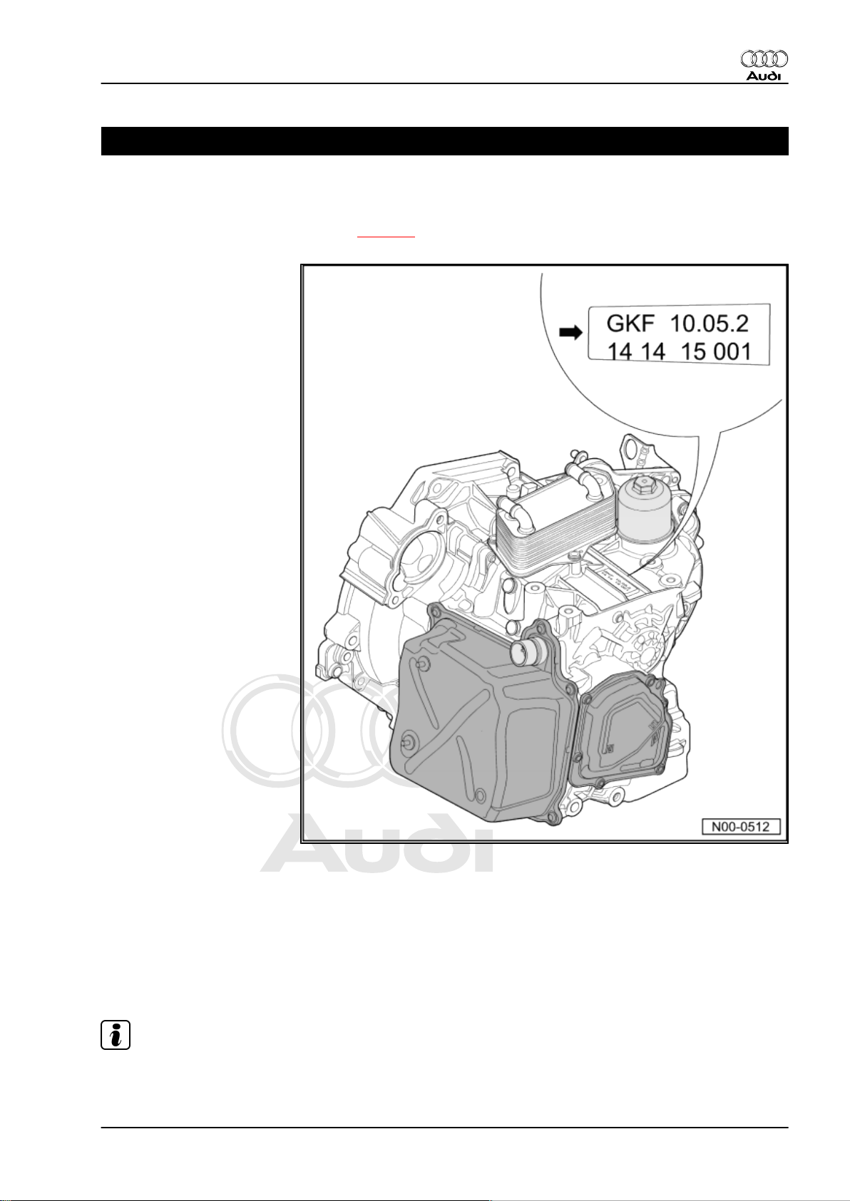
The gearbox code is located on the top of the gearbox, near the
gearbox oil cooler.
Example:
♦ GKF = gearbox code
♦ 10.05.2 = date of production: 10th May 2002
♦ The other figures are production-related.
Note
The gearbox code letters are also given on the vehicle data stick‐
ers.
1. Gearbox identification 1
Page 6
Protected by copyright. Copying for private or commercial purposes, in part or in whole, is not
permitted unless authorised by AUDI AG. AUDI AG does not guarantee or accept any liability
with respect to the correctness of information in this document. Copyright by AUDI AG.
Audi TT 2007 ➤
Direct shift gearbox 02E, four-wheel drive - Edition 08.2008
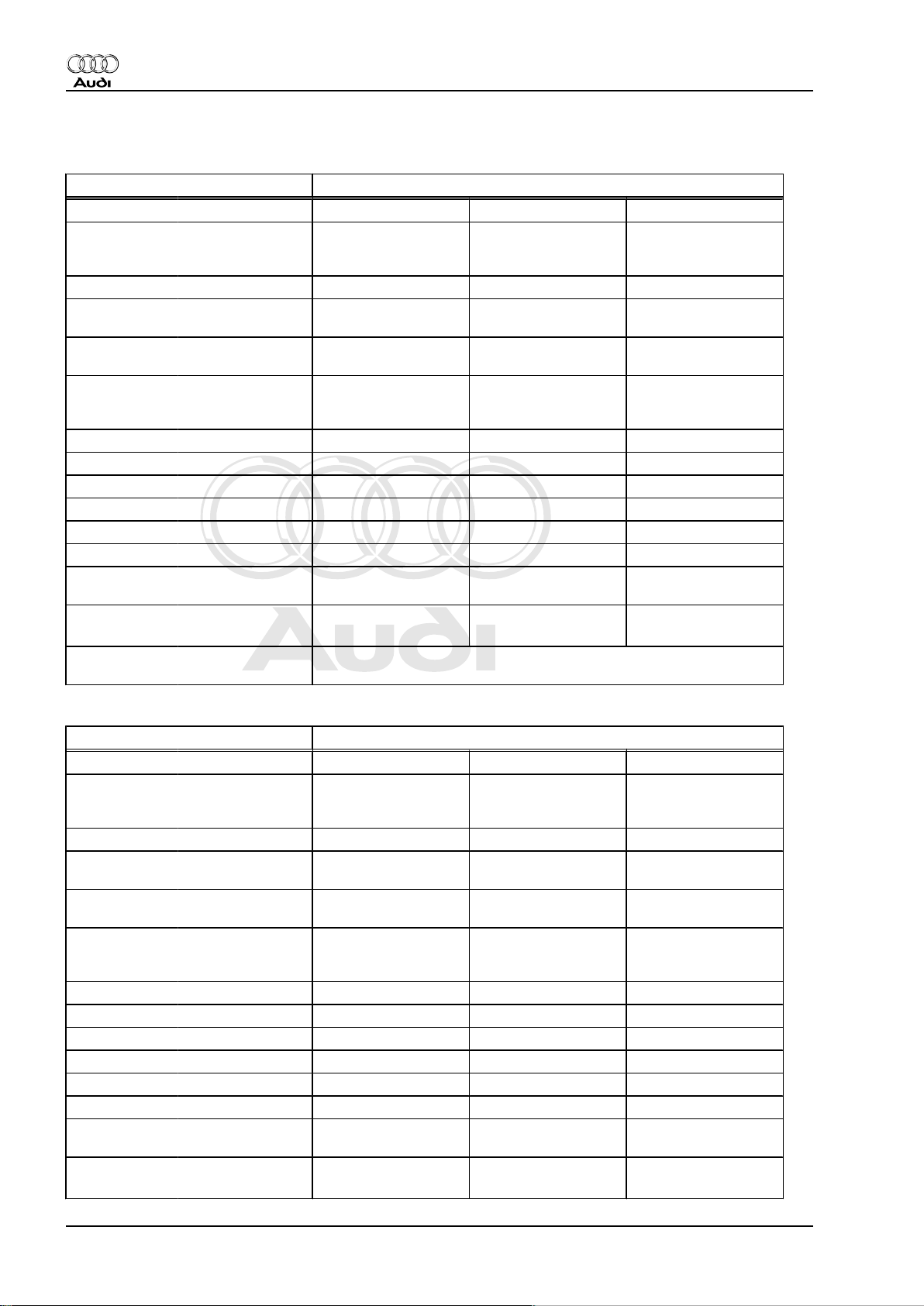
2 Code letters, gearbox allocation, ratios, equipment
Direct shift gearbox 02E four-wheel drive
Gearbox Code letters HXZ JFP JPZ
Allocation Model
Ratios Final drive I
Z2 : Z
1
Overall ratio
i
in top gear
ov.
Allocation: rear
final drive
Direct shift gearbox 02E four-wheel drive
Gearbox Code letters JUQ JYX KDE
Allocation Model
Ratios Final drive I
Z2 : Z
1
Overall ratio
i
in top gear
ov.
Manufac‐
tured
fro
m
05.06 05.08 11.06
to
Engine
Audi TT 2007 ▸ Audi TT 2007 ▸ Audi TT 2007 ▸
3.2 ltr. - 184 kW
6-cyl. MPI
2.0 ltr. - 147 kW
4-cyl. TFSI
72 : 15 = 4.800 69 : 17 = 4.059 72 : 15 = 4.800
for 1st to 4th gear
Final drive II
72 : 20 = 3.600 69 : 22 = 3.136 72 : 20 = 3.600
for 5th/6th gear
and reverse gear
1st gear
2nd gear
3rd gear
4th gear
5th gear
6th gear
Reverse
gear
44 : 15 = 2.933 45 : 13 = 3.462 44 : 15 = 2.933
44 : 24 = 1.833 43 : 20 = 2.150 44 : 24 = 1.833
39 : 30 = 1.300 41 : 28 = 1.464 39 : 30 = 1.300
39 : 40 = 0.975 41 : 38 = 1.079 39 : 40 = 0.975
34 : 33 = 1.030 35 : 32 = 1.093 34 : 33 = 1.030
33 : 40 = 0.825 35 : 38 = 0.921 33 : 40 = 0.825
22 : 14 x 32 : 15 =
3.352
22 : 14 x 33 : 13 =
3.352
2.970 2.888 2.970
Designation Rear final drive 02D and 0AV
Manufac‐
tured
fro
m
11.06 11.06 09.07
to
Engine
Audi TT 2007 ▸ Audi TT 2007 ▸ Audi TT 2007 ▸
3.2 ltr. - 184 kW
6-cyl. MPI
3.2 ltr. - 184 kW
6-cyl. MPI
72 : 15 = 4.800 72 : 15 = 4.800 72 : 15 = 4.800
for 1st to 4th gear
Final drive II
72 : 20 = 3.600 72 : 20 = 3.600 72 : 20 = 3.600
for 5th/6th gear
and reverse gear
1st gear
2nd gear
3rd gear
4th gear
5th gear
6th gear
Reverse
gear
44 : 15 = 2.933 44 : 15 = 2.933 44 : 15 = 2.933
44 : 24 = 1.833 44 : 24 = 1.833 44 : 24 = 1.833
39 : 30 = 1.300 39 : 30 = 1.300 39 : 30 = 1.300
39 : 40 = 0.975 39 : 40 = 0.975 39 : 40 = 0.975
34 : 33 = 1.030 34 : 33 = 1.030 34 : 33 = 1.030
33 : 40 = 0.825 33 : 40 = 0.825 33 : 40 = 0.825
22 : 14 x 32 : 15 =
3.352
22 : 14 x 32 : 15 =
3.352
2.970 2.970 2.970
3.2 ltr. - 184 kW
6-cyl. MPI
22 : 14 x 32 : 15 =
3.352
3.2 ltr. - 184 kW
6-cyl. MPI
22 : 14 x 32 : 15 =
3.352
2 Rep. Gr.00 - Technical data
Page 7
Protected by copyright. Copying for private or commercial purposes, in part or in whole, is not
permitted unless authorised by AUDI AG. AUDI AG does not guarantee or accept any liability
with respect to the correctness of information in this document. Copyright by AUDI AG.
Audi TT 2007 ➤
Direct shift gearbox 02E, four-wheel drive - Edition 08.2008
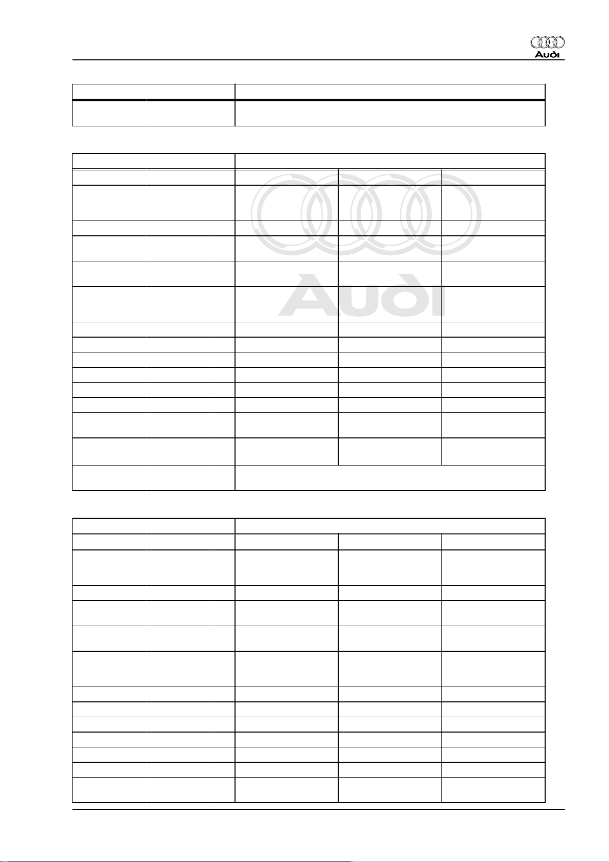
Direct shift gearbox 02E four-wheel drive
Allocation: rear
Designation Rear final drive 02D and 0AV
final drive
Direct shift gearbox 02E four-wheel drive
Gearbox Code letters KNL KNN KQA
Manufac‐
tured
fro
m
11.07 05.08 05.08
to
Allocation Model
Engine
Ratios Final drive I
Audi TT 2007 ▸ Audi TT 2007 ▸ Audi TT 2007 ▸
3.2 ltr. - 184 kW
6-cyl. MPI
2.0 ltr. - 195, 199 kW
4-cyl. TFSI
3.2 ltr. - 184 kW
6-cyl. MPI
72 : 15 = 4.800 62 : 13 = 4.769 72 : 15 = 4.800
for 1st to 4th gear
Z2 : Z
1
Final drive II
72 : 20 = 3.600 62 : 18 = 3.444 72 : 20 = 3.600
for 5th/6th gear
and reverse gear
Overall ratio
i
in top gear
ov.
Allocation: rear
1st gear
2nd gear
3rd gear
4th gear
5th gear
6th gear
Reverse
gear
Designation Rear final drive 02D and 0AV
44 : 15 = 2.933 38 : 13 = 2.923 44 : 15 = 2.933
44 : 24 = 1.833 45 : 23 = 1.957 44 : 24 = 1.833
39 : 30 = 1.300 35 : 25 = 1.400 39 : 30 = 1.300
39 : 40 = 0.975 32 : 31 = 1.032 39 : 40 = 0.975
34 : 33 = 1.030 28 : 26 = 1.077 34 : 33 = 1.030
33 : 40 = 0.825 27 : 31 = 0.871 33 : 40 = 0.825
22 : 14 x 32 : 15 =
3.352
22 : 14 x 27 : 13 =
3.264
22 : 14 x 32 : 15 =
3.352
2.970 3.000 2.970
final drive
Direct shift gearbox 02E four-wheel drive
Gearbox Code letters KRF LME
Manufac‐
tured
fro
m
01.08 01.08
to
Allocation Model
Engine
Ratios Final drive I
Audi TT 2007 ▸ Audi TT 2007 ▸
2.0 ltr. - 195, 200 kW
4-cyl. TFSI
62 : 13 = 4.769 62 : 13 = 4.769
2.0 ltr. - 155 kW
4-cyl. TFSI
for 1st to 4th gear
Z2 : Z
1
Final drive II
62 : 18 = 3.444 62 : 18 = 3.444
for 5th/6th gear
and reverse gear
1st gear
2nd gear
3rd gear
4th gear
5th gear
6th gear
Reverse
gear
38 : 13 = 2.923 38 : 13 = 2.923
45 : 23 = 1.957 43 : 24 = 1.792
35 : 25 = 1.400 32 : 27 = 1.185
32 : 31 = 1.032 29 : 35 = 0.829
28 : 26 = 1.077 25 : 29 = 0.862
27 : 31 = 0.871 24 : 35 = 0.686
22 : 14 x 27 : 13 =
3.264
22 : 14 x 27 : 13 =
3.264
2. Code letters, gearbox allocation, ratios, equipment 3
Page 8
Protected by copyright. Copying for private or commercial purposes, in part or in whole, is not
permitted unless authorised by AUDI AG. AUDI AG does not guarantee or accept any liability
with respect to the correctness of information in this document. Copyright by AUDI AG.
Audi TT 2007 ➤
Direct shift gearbox 02E, four-wheel drive - Edition 08.2008
Direct shift gearbox 02E four-wheel drive
Overall ratio
i
in top gear
ov.
Allocation: rear
3.000 2.362
Designation Rear final drive 02D and 0AV
final drive
2.1 Calculating ratio “i”
Example:
6th gear Final drive
Drive gear ZG1 = 40 ZA1 = 20
Driven gear ZG2 = 33 ZA2 = 72
i = Z2 : Z1 (Z1 = number of teeth on drive gear, Z2 = number of
teeth on driven gear)
iG = gear ratio = ZG2 : ZG1 = 33 : 40 = 0.825
iA = axle ratio = ZA2 : ZA1 = 72 : 20 = 3.6
iov = overall ratio = iG x iA = 0.825 x 3.6 = 2.97
4 Rep. Gr.00 - Technical data
Page 9
Protected by copyright. Copying for private or commercial purposes, in part or in whole, is not
permitted unless authorised by AUDI AG. AUDI AG does not guarantee or accept any liability
with respect to the correctness of information in this document. Copyright by AUDI AG.
Direct shift gearbox 02E, four-wheel drive - Edition 08.2008
3 Capacities
Gearbox capacity
Capacities Direct shift gearbox 02E, four-wheel
drive
Initial filling 6.9 ltr.
Oil change approx. 5.5 ltr.
Change interval ⇒ Maintenance tables
Lubricant Gear oil for direct shift gearbox 02E
⇒ Electronic parts catalogue
Note
♦
Use only the correct type of gear oil for the direct shift gearbox
02E (available as a replacement part). Other types of lubricant
cause malfunctions and/or failure of the gearbox.
♦
You must also renew the gear oil filter when you change the
gear oil ⇒ page 105 .
Audi TT 2007 ➤
– Checking gear oil level and topping up ⇒ page 94
– Filling up with gear oil after repair ⇒ page 100
Bevel box capacity
Capacities Bevel box
Initial filling 0.9 ltr.
Oil change Filled for life, no change
Lubricant Gear oil ⇒ Electronic parts cata‐
logue .
Note
Use only the correct type of gear oil (available as a replacement
part) for the bevel box. Other types of oil cause malfunctions and/
or failure of the bevel box.
– Checking gear oil level and topping up ⇒ page 149
– Filling up with gear oil after repair ⇒ page 150
3. Capacities 5
Page 10
Protected by copyright. Copying for private or commercial purposes, in part or in whole, is not
permitted unless authorised by AUDI AG. AUDI AG does not guarantee or accept any liability
with respect to the correctness of information in this document. Copyright by AUDI AG.
Audi TT 2007 ➤
Direct shift gearbox 02E, four-wheel drive - Edition 08.2008
4 Safety precautions
Observe the following precautions if tests have to be performed
with the engine running.
WARNING
Accidents can be caused if a gear is inadvertently engaged
while the engine is running.
♦ Before working on the vehicle while the engine is running,
shift the selector lever into position “P” and apply the
handbrake.
Danger from toxic fumes!
♦ When the engine is running, the exhaust system must al‐
ways be connected to the exhaust gas extractor.
6 Rep. Gr.00 - Technical data
Page 11
Protected by copyright. Copying for private or commercial purposes, in part or in whole, is not
permitted unless authorised by AUDI AG. AUDI AG does not guarantee or accept any liability
with respect to the correctness of information in this document. Copyright by AUDI AG.
Direct shift gearbox 02E, four-wheel drive - Edition 08.2008
Observe the following precautions if test equipment has to be
used while road-testing the vehicle:
WARNING
Accidents can be caused if the driver is distracted by test
equipment while road-testing, or if test equipment is not se‐
cured.
Injuries can also be caused if the passenger's airbag is trig‐
gered in a collision.
• The use of test equipment while driving causes distraction.
• There is an increased risk of injury if test equipment is not
secured.
TT Coupé:
Always secure testing equipment to the rear seat with a strap
and have them operated from there by a second person.
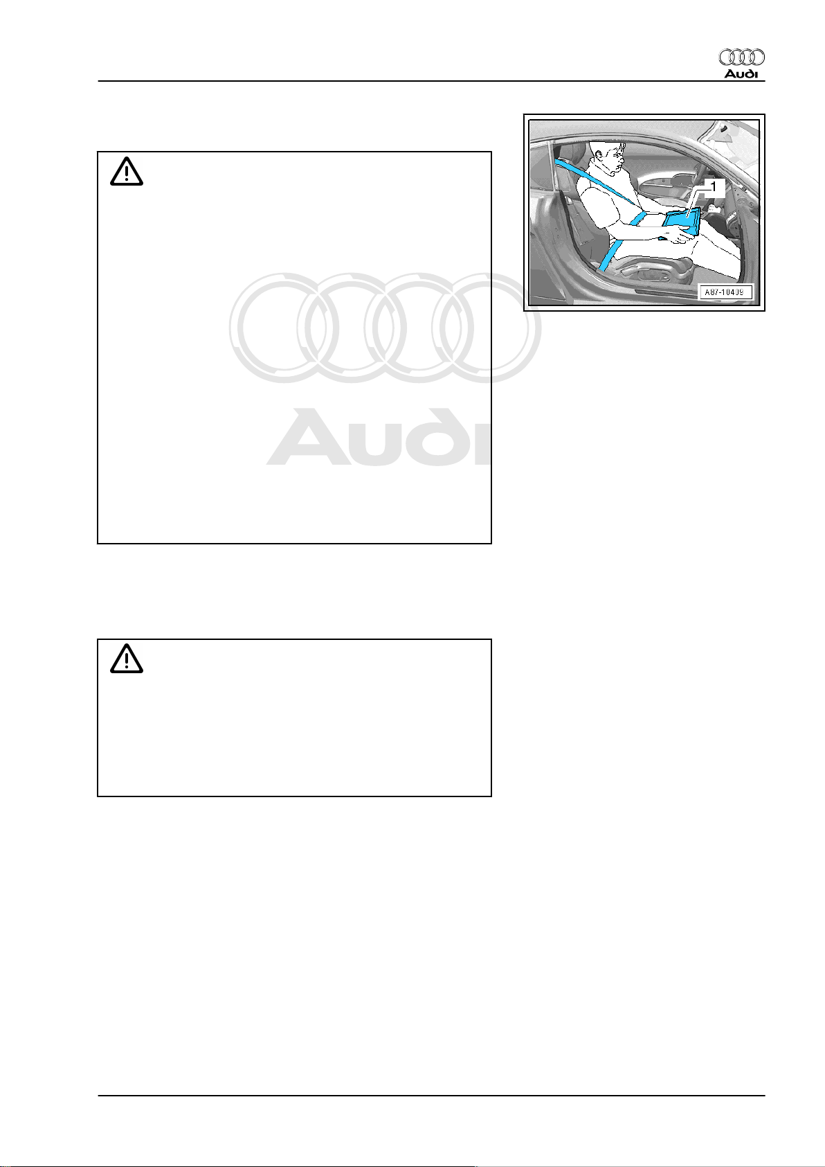
TT Roadster:
♦ Move the passenger's seat to the rearmost position.
♦ Use only vehicle diagnosis and service information sys‐
tem -VAS 5052- or diagnosis system -VAS 5053- .
♦ Test equipment may only be operated by the passenger;
the tester -1- must be placed flat on the passenger's lap
as illustrated.
Audi TT 2007 ➤
Observe the following precautions to avoid possible injury and/or
damage to electrical and electronic components:
♦ Switch off ignition before disconnecting and connecting test
equipment.
Caution
When disconnecting the battery there is a risk of serious dam‐
age to electronic components:
♦ Observe the correct procedure for disconnecting the bat‐
tery.
♦ Always switch off the ignition before disconnecting the
battery.
4. Safety precautions 7
Page 12
Protected by copyright. Copying for private or commercial purposes, in part or in whole, is not
permitted unless authorised by AUDI AG. AUDI AG does not guarantee or accept any liability
with respect to the correctness of information in this document. Copyright by AUDI AG.
Audi TT 2007 ➤
Direct shift gearbox 02E, four-wheel drive - Edition 08.2008
5 Notes on the direct shift gearbox 02E
5.1 General notes
Gearbox
The direct shift gearbox 02E is a dual-clutch gearbox, also refer‐
red to as “S tronic”. It has the same basic construction as a 6speed manual gearbox. The engine torque is transferred to the
gearbox via the dual-mass flywheel. The two multi-plate "wet"
clutches are controlled hydraulically and actuated alternately so
that the gearbox is operated like an automatic gearbox, in other
words the gears are engaged automatically (but can also be se‐
lected manually via the tiptronic function). There is no clutch
pedal. For further information please refer to ⇒ Self-study pro‐
gramme No. 308 ; Direct shift gearbox 02E .
Selector mechanism
In selector lever position “P” the selector lever cable is used to
engage the parking lock mechanically. All other gearshift com‐
mands and selector lever positions are transmitted via the CAN
data bus from the selector lever -E313- (selector mechanism) to
the mechatronic unit for dual clutch gearbox -J743- .
Gear oil (gearbox and final drive)
The direct shift gearbox and front final drive have a common filling
of gear oil ⇒ page 94 .
Note
Use only the correct type of gear oil for the direct shift gearbox
02E (available as a replacement part). Other types of oil will cause
malfunctions and/or failure of the gearbox; for Part No. refer to ⇒
Electronic parts catalogue .
The bevel box has a separate oil filling ⇒ page 149 .
Note
Use only the correct type of gear oil (available as a replacement
part) for the bevel box. Other types of oil will cause malfunctions
and/or failure of the bevel box; for Part No. refer to ⇒ Electronic
parts catalogue .
Regulations for the disposal of oil
Drained oil must be disposed of properly.
♦ Improper disposal of used oil endangers the environment.
♦ It must not be mixed with solvents, brake fluid, coolant or sim‐
ilar.
♦ Please observe the information shown on the packaging of the
oil.
Variation of gear-change points for gradients
Additional gear-change maps automatically select the gearchange points for gradients according to accelerator pedal posi‐
tion and road speed.
• The gear-change map for extreme uphill gradients is matched
to the engine power.
8 Rep. Gr.00 - Technical data
Page 13

Protected by copyright. Copying for private or commercial purposes, in part or in whole, is not
permitted unless authorised by AUDI AG. AUDI AG does not guarantee or accept any liability
with respect to the correctness of information in this document. Copyright by AUDI AG.
Direct shift gearbox 02E, four-wheel drive - Edition 08.2008
• The gear-change map for extreme downhill gradients is
matched to the engine braking effect.
• By selecting a gear directly via the tiptronic mode, it is possible
to make use of the engine braking effect available in a partic‐
ular gear, for instance when driving downhill with a trailer.
5.2 Safety functions of gearbox control unit
In the event of a failure of one or more components or sensors,
the control unit J743 will activate appropriate backup functions.
This enables the gearbox to continue operating without damage,
but will impair the operation and smoothness of the gearshifts.
Faults detected by the gearbox are classified in four different cat‐
egories.
1 - The fault is stored in the memory and one of the backup
programs is activated. The gear selection indicator in the
instrument cluster will continue to show the currently en‐
gaged selector lever position in the normal way. The driver
can continue to drive the vehicle (with certain restrictions),
and the condition is not critical to the safety of the vehicle or
to the gearbox itself. If at all, the driver will only notice the
fault if he experiences driveability problems, and will then
automatically contact an Audi Service Partner.
2 - Certain positions on the gear selection indicator in the in‐
strument cluster start to flash. This is to inform the driver that
this particular selector lever position is currently not availa‐
ble. Example: position "D" will start flashing if the selector
lever is moved from position "R" to position "D" while the
vehicle is still rolling backwards. To avoid damage to the
gearbox, the mechatronic unit for dual clutch gearbox -J743prevents 1st gear from being engaged while the vehicle is
moving backwards. 1st gear will only be engaged when the
vehicle comes to a standstill.
3 - The complete gear selection indicator lights up and flashes;
the currently engaged selector lever position is highlighted.
This shows the driver that a temporary critical fault in the
gearbox has been detected. Example: the gearbox has
been overloaded or overheated, for instance by towing an
excessively heavy load. The driver can continue to drive the
vehicle when the gearbox has cooled off, but will need to
avoid placing a heavy load on the transmission.
4 - The gear selection indicator flashes; the currently engaged
selector lever position is no longer indicated. This shows the
driver that a critical and permanent fault in the gearbox has
been detected. It may no longer be possible to use all gears,
so this condition is critical to the safety of the vehicle and to
the gearbox itself. This display is intended to warn the driver
that he should contact an Audi Service Partner.
Audi TT 2007 ➤
5. Notes on the direct shift gearbox 02E 9
Page 14
Protected by copyright. Copying for private or commercial purposes, in part or in whole, is not
permitted unless authorised by AUDI AG. AUDI AG does not guarantee or accept any liability
with respect to the correctness of information in this document. Copyright by AUDI AG.
Audi TT 2007 ➤
Direct shift gearbox 02E, four-wheel drive - Edition 08.2008
6 Notes on tow-starting and towing
Caution
Risk of damage to the gearbox.
♦ The selector lever must be in position “N” when the vehicle
is towed.
♦ The vehicle must not be towed further than 50 km or at a
speed in excess of 50 km/h.
Note
It is not possible to start the engine by tow-starting, for instance
if the battery is discharged or if the starter is not working.
10 Rep. Gr.00 - Technical data
Page 15

Protected by copyright. Copying for private or commercial purposes, in part or in whole, is not
permitted unless authorised by AUDI AG. AUDI AG does not guarantee or accept any liability
with respect to the correctness of information in this document. Copyright by AUDI AG.
Direct shift gearbox 02E, four-wheel drive - Edition 08.2008
7 Repair instructions
Proper tools and the maximum possible care and cleanliness are
essential for satisfactory gearbox repairs. The usual basic safety
precautions also naturally apply when carrying out repair work.
A number of generally applicable instructions for the various re‐
pair procedures are summarised here. They apply to the work
described in this Manual.
Guided fault finding, vehicle self-diagnosis and testing system
♦ Before servicing the gearbox, the exact cause of the failure
must be determined using the functions “Guided Fault Find‐
ing”, “Vehicle Self-diagnosis” and “Test Instruments” ⇒ Vehicle
diagnosis, testing and information system VAS 5051.
Special tools
For a complete list of special tools used in this Workshop Manual
⇒ "Workshop equipment and special tools" .
Gearbox
♦ Do not run the engine or tow the vehicle with the oil pan re‐
moved or when there is no gear oil in the gearbox.
♦ When installing a replacement gearbox, check the gear oil
level and top up as required ⇒ page 94 : capacities
⇒ page 5 ; specification ⇒ Electronic parts catalogue .
♦ When installing gearbox, ensure that dowel sleeves are fitted
correctly.
Audi TT 2007 ➤
7. Repair instructions 11
Page 16
Protected by copyright. Copying for private or commercial purposes, in part or in whole, is not
permitted unless authorised by AUDI AG. AUDI AG does not guarantee or accept any liability
with respect to the correctness of information in this document. Copyright by AUDI AG.
Audi TT 2007 ➤
Direct shift gearbox 02E, four-wheel drive - Edition 08.2008
O-rings, oil seals and gaskets
♦ Renew O-rings, oil seals and gaskets.
♦ After removing gaskets and seals, always inspect the contact
surface on the housing or shaft for burrs resulting from removal
or for other signs of damage.
♦ Renew gaskets: completely remove the old gasket and clean
the sealing surfaces thoroughly.
♦ Lightly lubricate O-rings with gear oil before installation to pre‐
vent them being trapped and damaged during assembly.
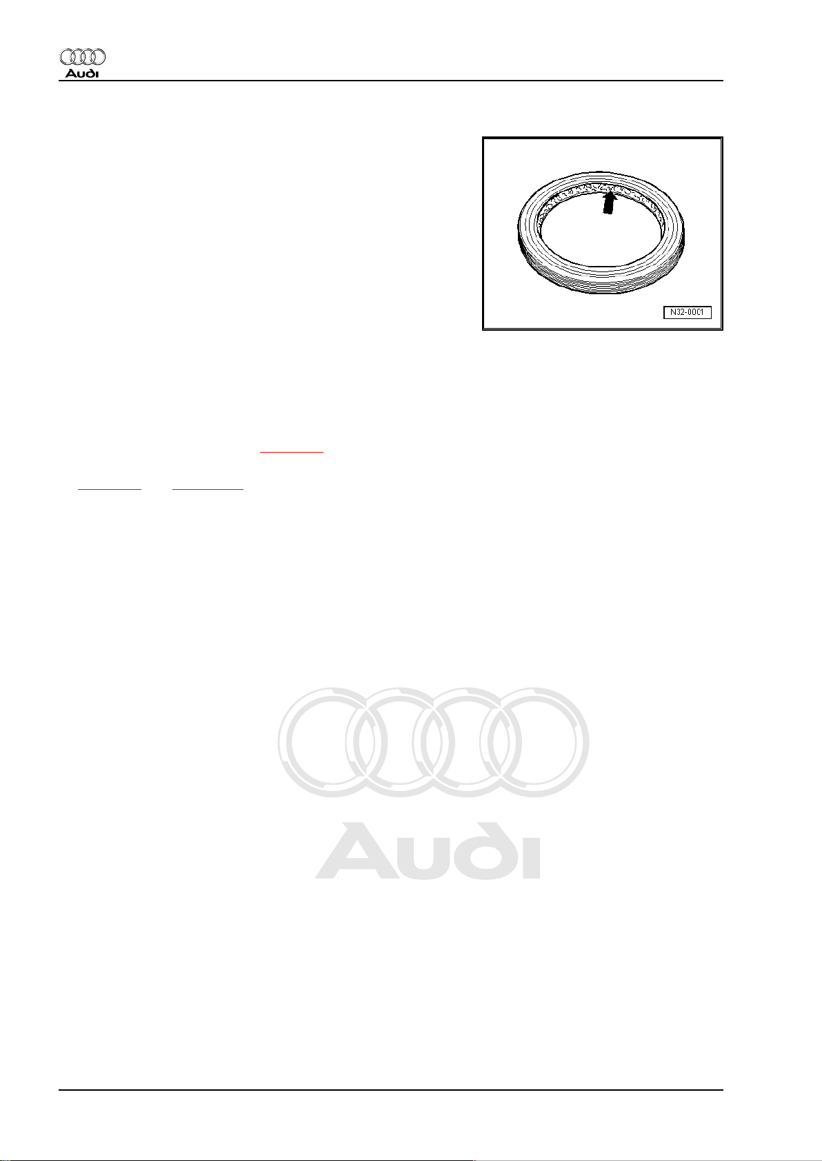
♦ Lightly oil the outer circumference of oil seals and pack the
space between the sealing lips -arrow- about half-full with
sealing grease; for sealing grease refer to ⇒ Electronic parts
catalogue .
♦ Do not use any other lubricants where gear oil is specified.
Otherwise, there is a risk of problems occurring in the gearbox
hydraulics.
♦ The open side of the oil seal should face the side containing
the fluid.
♦ Observe rules for cleanliness ⇒ page 14 .
♦ After installation, check gear oil level and top up as required
⇒ page 94 and ⇒ page 149 .
Locking elements
♦ Do not overstretch circlips; renew if necessary.
♦ Circlips must be properly seated in the base of the groove.
Nuts, bolts
♦ Slacken bolts in reverse sequence to the specified tightening
sequence.
♦ Nuts and bolts which secure covers and housings should be
loosened and tightened in diagonal sequence and in stages if
no tightening sequence is specified.
♦ Renew self-locking nuts.
♦ Use a wire brush to clean the threads of bolts which are se‐
cured with locking fluid. Then install bolts with locking fluid; for
locking fluid refer to ⇒ Electronic parts catalogue .
♦ The tightening torques stated apply to non-oiled nuts and
bolts.
♦ Where instructions specify a torque setting plus an additional
angle, these bolts must be tightened to the specified torque
and then turned through the specified angle, e.g. 40 Nm + 90°
(90° = a quarter turn).
7.1 Contact corrosion!
Contact corrosion can occur if non-approved fasteners are used
on the vehicle (bolts, nuts, washers etc.).
For this reason, only fasteners with a special surface coating are
fitted.
Rubber or plastic parts and adhesives also consist of non-con‐
ductive materials.
If you are not sure whether used parts can be re-installed, always
fit new parts ⇒ Electronic parts catalogue .
12 Rep. Gr.00 - Technical data
Page 17

Protected by copyright. Copying for private or commercial purposes, in part or in whole, is not
permitted unless authorised by AUDI AG. AUDI AG does not guarantee or accept any liability
with respect to the correctness of information in this document. Copyright by AUDI AG.
Direct shift gearbox 02E, four-wheel drive - Edition 08.2008
Please note:
♦ Use only genuine spare parts: these have been fully tested
and are compatible with aluminium.
♦ We recommend the use of accessories approved by Audi.
♦ Damage resulting from contact corrosion is not covered by the
warranty.
Audi TT 2007 ➤
7. Repair instructions 13
Page 18

Protected by copyright. Copying for private or commercial purposes, in part or in whole, is not
permitted unless authorised by AUDI AG. AUDI AG does not guarantee or accept any liability
with respect to the correctness of information in this document. Copyright by AUDI AG.
Audi TT 2007 ➤
Direct shift gearbox 02E, four-wheel drive - Edition 08.2008
8 Rules for cleanliness
♦ Carefully clean connection points and the surrounding area
with engine cleaner or brake cleaner and dry thoroughly before
opening.
♦ Seal off open lines and connections with clean plugs or sealing
caps immediately.
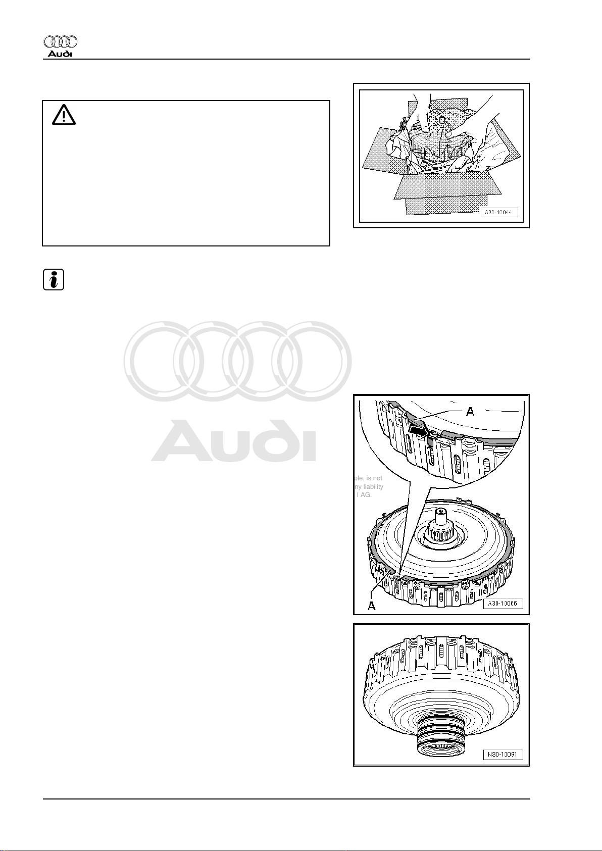
♦ Place removed parts on a clean surface and cover them over.
Use only lint-free cloths.
♦ Carefully cover or seal open components if repairs cannot be
completed immediately.
♦ Only install clean components: do not remove replacement
parts from packaging until just before installation.
♦ Protect unplugged electrical connectors against dirt and mois‐
ture and make sure connections are dry when attaching.
14 Rep. Gr.00 - Technical data
Page 19
Protected by copyright. Copying for private or commercial purposes, in part or in whole, is not
permitted unless authorised by AUDI AG. AUDI AG does not guarantee or accept any liability
with respect to the correctness of information in this document. Copyright by AUDI AG.
Direct shift gearbox 02E, four-wheel drive - Edition 08.2008
30 – Clutch
1 Exploded view - servicing multiple clutch
♦ The clutch in the direct shift gearbox 02E consists of two sets
of plates, or clutch packs, and is therefore referred to as a
“multiple clutch”. The larger clutch pack (located on the out‐
side) is designated “K 1” (clutch 1), and controls the torque
flow for reverse gear and gears “1”, “3” and “5”. The smaller
set of plates (on the inside) is designated “K 2” (clutch 2), and
controls the torque flow for gears “2”, “4” and “6”.
♦ Any work performed on the multiple clutch requires extra care
because all the parts are balanced and matched together in
production. If the components are rotated out of their original
positions when repairing, this will cause imbalance and impair
the smoothness of the gear-changes and reduce the service
life of the unit.
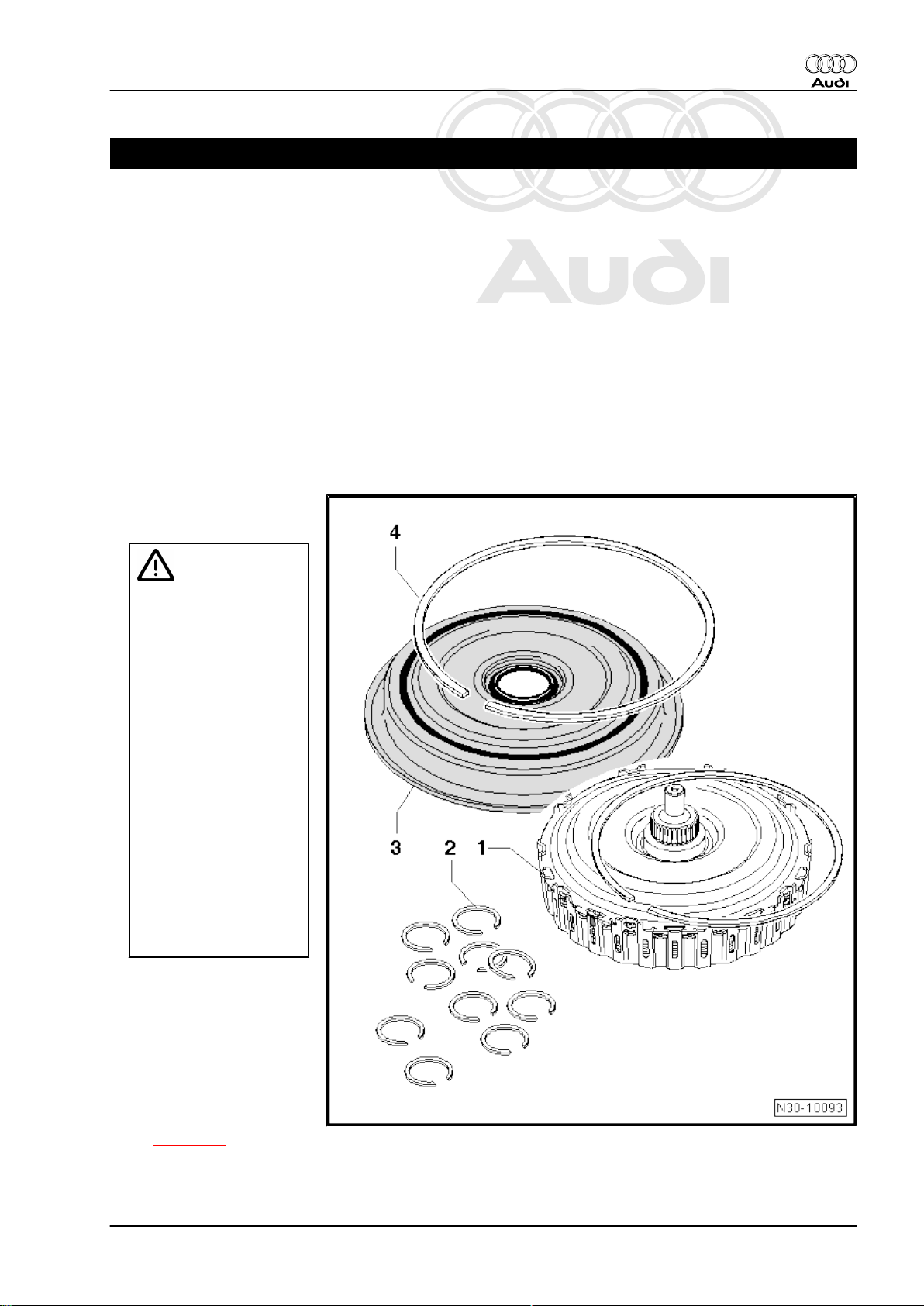
Replacement parts
1 - Multiple clutch
❑ With circlip
Audi TT 2007 ➤
Caution
The clutch plates can slip
out of position inside the
multiple clutch unit.
♦The multiple clutch unit
must not be dismantled
at present.
♦If the drive plate (which
forms the upper section
of the multiple clutch unit)
becomes detached from
the splines in the outer
plate carrier, the clutch
plates can slip out of po‐
sition in the clutch. It will
then no longer be possi‐
ble to adjust the clutch
correctly.
♦The drive plate included
with the replacement part
is not secured with the
large circlip; it is only a
close fit inside the clutch.
❑ Removing and installing
⇒ page 17
2 - Circlips
❑ 10x, with different thick‐
nesses for adjusting
multiple clutch
❑ Determining correct
thickness when instal‐
ling multiple clutch
⇒ page 22
3 - Clutch end cover
4 - Corrugated ring
1. Exploded view - servicing multiple clutch 15
Page 20
Protected by copyright. Copying for private or commercial purposes, in part or in whole, is not
permitted unless authorised by AUDI AG. AUDI AG does not guarantee or accept any liability
with respect to the correctness of information in this document. Copyright by AUDI AG.
Audi TT 2007 ➤
Direct shift gearbox 02E, four-wheel drive - Edition 08.2008
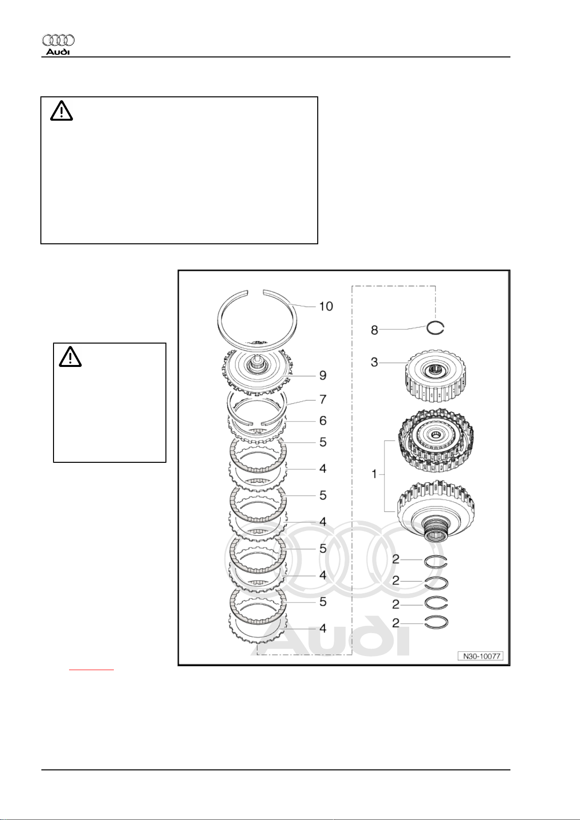
Component parts of dismantled multiple clutch
Caution
The clutch plates can slip out of position inside the multiple
clutch unit.
♦ This diagram showing the components of the multiple
clutch is for information only. The multiple clutch unit must
not be dismantled at present.
♦ If the drive plate becomes detached from the splines in the
outer plate carrier, the clutch plates can slip out of position
in the multiple clutch. It will then no longer be possible to
adjust the clutch correctly.
1 - Outer plate carrier with
clutch housing.
2 - Oil seals
❑ 4x
3 - Inner plate carrier
Caution
The clutch plates can slip
out of position.
♦If the inner plate carrier is
lifted or taken out, the
plates can slip out of po‐
sition inside the clutch. It
will then no longer be
possible to adjust the
clutch correctly.
4 - Outer plates
❑ 4x
5 - Inner plates
❑ 4x
6 - Thrust washer
7 - Circlip
❑ Fit a new circlip of the
same thickness if the
original circlip is re‐
moved in order to re-in‐
stall the clutch plates.
8 - Circlip
❑ Determining correct
thickness when instal‐
ling multiple clutch
⇒ page 22
9 - Drive plate
10 - Circlip
❑ Renew
16 Rep. Gr.30 - Clutch
Page 21
Protected by copyright. Copying for private or commercial purposes, in part or in whole, is not
permitted unless authorised by AUDI AG. AUDI AG does not guarantee or accept any liability
with respect to the correctness of information in this document. Copyright by AUDI AG.
Direct shift gearbox 02E, four-wheel drive - Edition 08.2008
1.1 Removing and installing multiple clutch
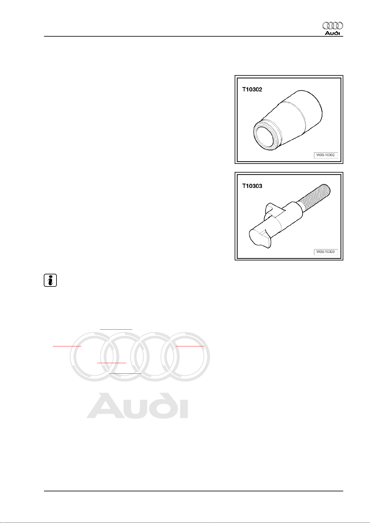
Special tools and workshop equipment required
♦ Assembly sleeve -T10302-
♦ Retaining pin -T10303-
Audi TT 2007 ➤
Note
Assembly sleeve -T10302- must be cleaned before use; do not
use an assembly sleeve if it is scratched.
Removing
– Drain off gear oil ⇒ page 100 .
– Remove direct shift gearbox: vehicles with 2.0 ltr. TFSI engine
⇒ page 53 , vehicles with 3.2 ltr. MPI engine ⇒ page 66 .
– Secure direct shift gearbox to engine and gearbox support in
vertical position ⇒ page 81 .
– Renew gear oil filter ⇒ page 105 .
1. Exploded view - servicing multiple clutch 17
Page 22
Protected by copyright. Copying for private or commercial purposes, in part or in whole, is not
permitted unless authorised by AUDI AG. AUDI AG does not guarantee or accept any liability
with respect to the correctness of information in this document. Copyright by AUDI AG.
Audi TT 2007 ➤
Direct shift gearbox 02E, four-wheel drive - Edition 08.2008
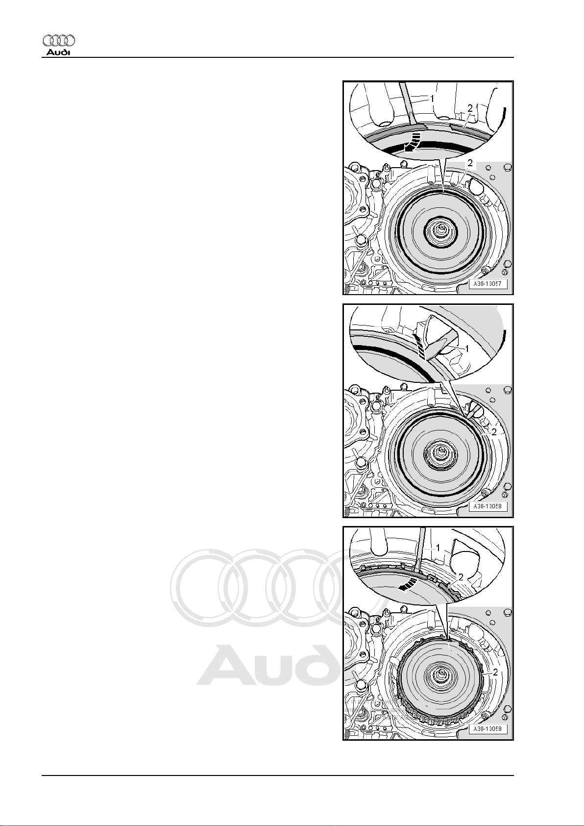
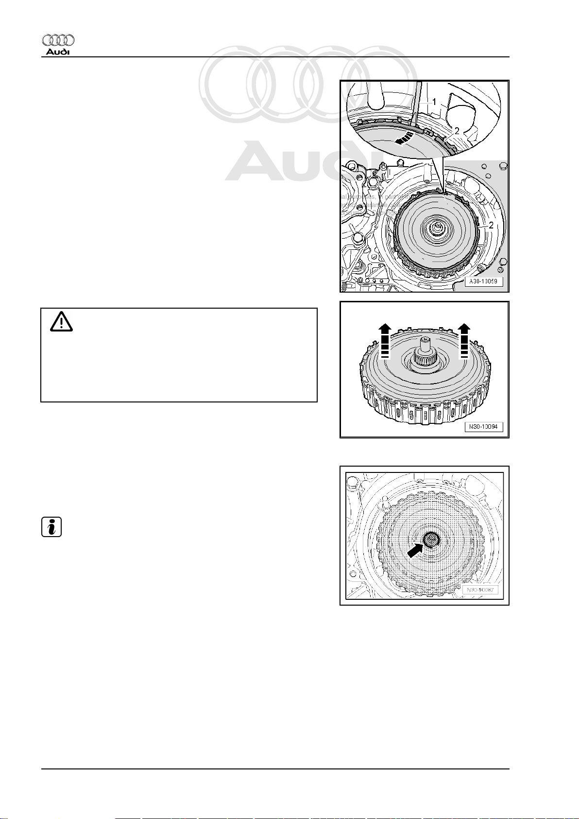
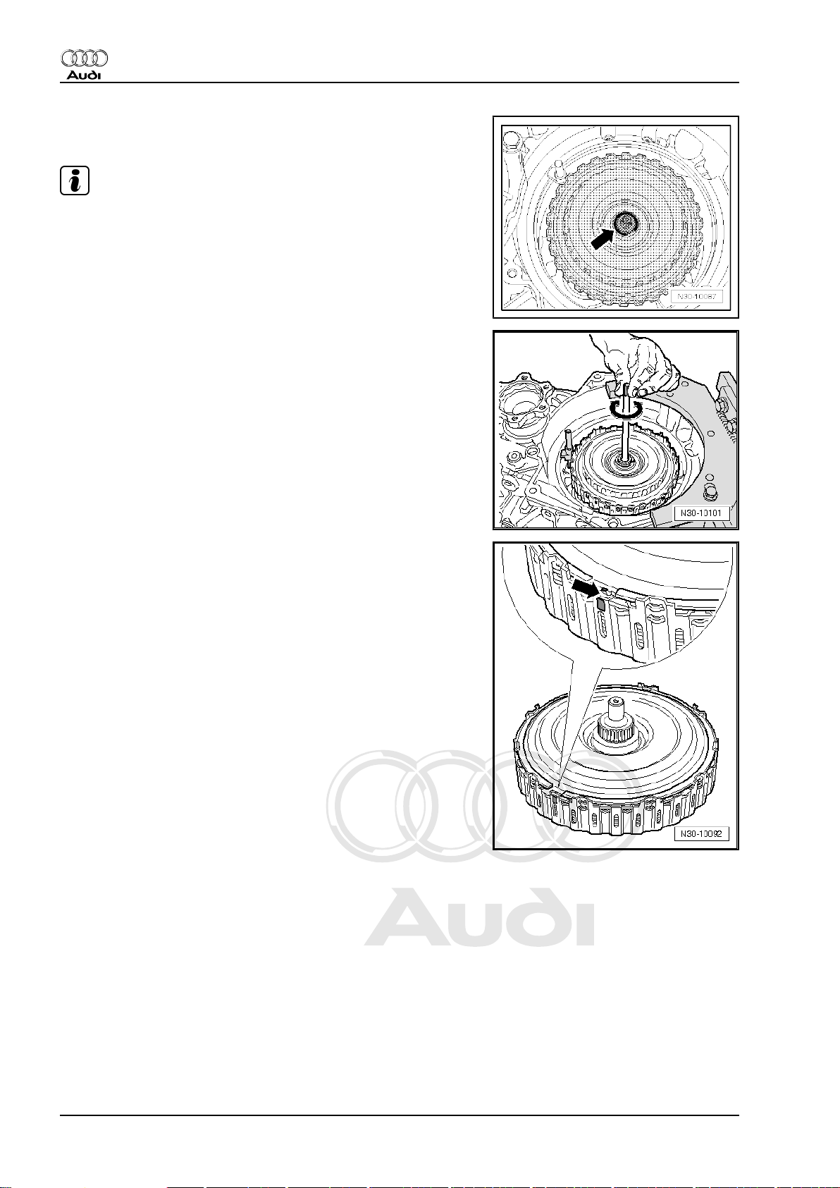
– Pry out and detach corrugated ring -2- for clutch end cover
using a screwdriver -1- -arrow-.
– Working through aperture for starter motor, pry out and detach
clutch end cover -2- using a screwdriver -1- or other suitable
lever -arrow-.
– Pry out circlip -2- for drive plate using a screwdriver -1-
-arrow-.
18 Rep. Gr.30 - Clutch
Page 23
Protected by copyright. Copying for private or commercial purposes, in part or in whole, is not
permitted unless authorised by AUDI AG. AUDI AG does not guarantee or accept any liability
with respect to the correctness of information in this document. Copyright by AUDI AG.
Direct shift gearbox 02E, four-wheel drive - Edition 08.2008
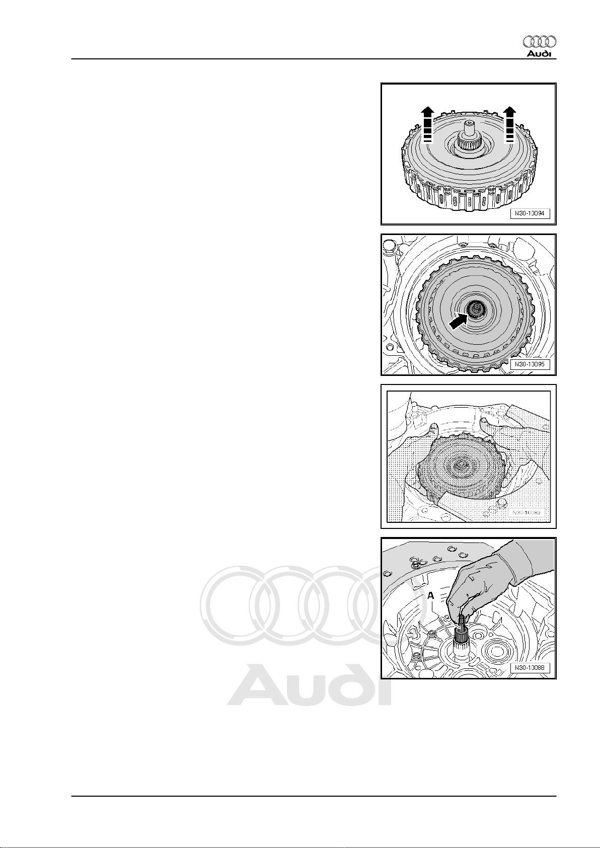
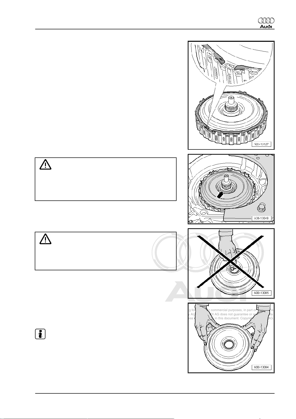
– Detach drive plate -arrows-.
– Pry out circlip -arrow- using a screwdriver or long-nose pliers.
Audi TT 2007 ➤
– Take multiple clutch out of gearbox.
– After removing multiple clutch, check whether clutch bell hous‐
ing was damaged during removal.
– Pull out pump shaft -A- and place to one side.
1. Exploded view - servicing multiple clutch 19
Page 24
Protected by copyright. Copying for private or commercial purposes, in part or in whole, is not
permitted unless authorised by AUDI AG. AUDI AG does not guarantee or accept any liability
with respect to the correctness of information in this document. Copyright by AUDI AG.
Audi TT 2007 ➤
Direct shift gearbox 02E, four-wheel drive - Edition 08.2008
Installing
Caution
The clutch plates can slip out of position inside the multiple
clutch unit.
♦ If the drive plate becomes detached from the splines in the
outer plate carrier, the clutch plates can slip out of position
in the multiple clutch. It will then no longer be possible to
adjust the clutch correctly.
♦ To prevent the clutch plates from slipping inside the mul‐
tiple clutch unit, keep the drive plate pressed into the outer
plate carrier with both thumbs during all following steps.
Note
The circlip for the drive plate that is supplied with the replacement
parts is fitted at a later stage.
– Take new circlip for drive plate out of packaging and place to
one side.
– Take multiple clutch out of packaging, holding drive plate in
position.
– First fit old circlip -A- for drive plate from removed multiple
clutch.
• Installation position: the lug on the drive plate and the colourmarked splines on the outer plate carrier must be located
between the ends of the circlip.
– Using a screwdriver, check that circlip is fully engaged.
– Check that the 4 oil seals on the hub on the underside of the
multiple clutch are correctly seated; engage in position if nec‐
essary.
• Installation position: joints of seals should be offset
20 Rep. Gr.30 - Clutch
Page 25
Protected by copyright. Copying for private or commercial purposes, in part or in whole, is not
permitted unless authorised by AUDI AG. AUDI AG does not guarantee or accept any liability
with respect to the correctness of information in this document. Copyright by AUDI AG.
Direct shift gearbox 02E, four-wheel drive - Edition 08.2008
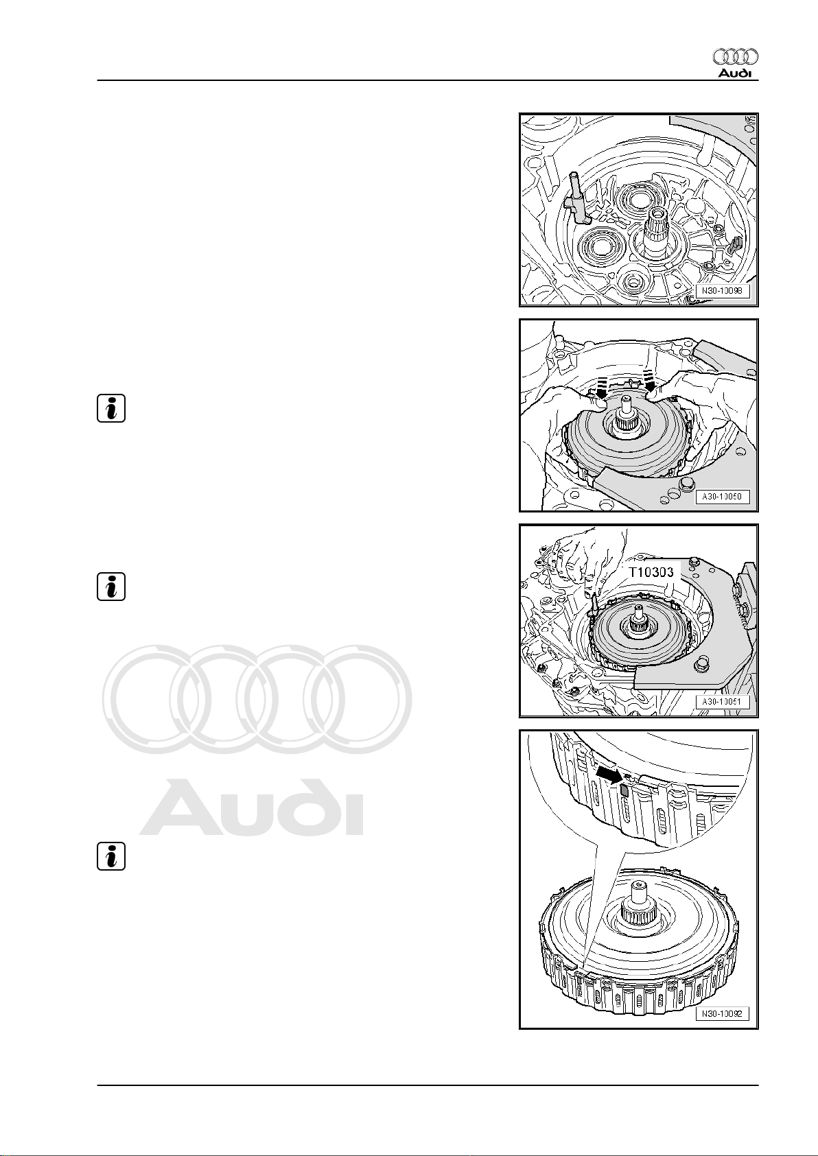
– Apply retaining pin -T10303- to seat of clutch end cover as
illustrated.
– Install multiple clutch in clutch bell housing (turn and move up
and down as required), at the same time keeping the drive
plate pressed into the outer plate carrier with both thumbs
-arrows-.
Note
Do not allow the multiple clutch to drop into the inner plate carrier.
Audi TT 2007 ➤
– Have a second mechanic hold the retaining pin -T10303- as
illustrated until the clutch end cover is installed.
Note
The multiple clutch must not be turned from this point onwards,
as this would turn the retaining pin -T10303- out of position.
– Check whether the projecting lug -arrow- on the drive plate is
positioned between the colour-marked splines on the outer
plate carrier.
– If no marking is provided, use waterproof pen to mark position
of drive plate in relation to outer rim of outer plate carrier as
illustrated so it can be re-fitted in the same position.
Note
When re-assembling, the lug on the drive plate must be located
again at this marked position.
1. Exploded view - servicing multiple clutch 21
Page 26
Protected by copyright. Copying for private or commercial purposes, in part or in whole, is not
permitted unless authorised by AUDI AG. AUDI AG does not guarantee or accept any liability
with respect to the correctness of information in this document. Copyright by AUDI AG.
Audi TT 2007 ➤
Direct shift gearbox 02E, four-wheel drive - Edition 08.2008
– Pry out old circlip -2- using a screwdriver -1- -arrow-.
Caution
The clutch plates can slip out of position inside the multiple
clutch unit.
♦ If the inner plate carrier is taken out or lifted, the plates can
slip out of position inside the clutch. It will then no longer
be possible to adjust the clutch correctly.
– Lift out drive plate -arrows-; if necessary lever it carefully out
of splines on outer plate carrier using a screwdriver.
– Place drive plate to one side.
Adjusting multiple clutch (determining thickness of circlip)
– Select the 2 mm thick circlip from the circlips supplied with the
unit.
Note
The 2 mm circlip is fitted provisionally for measurement purposes
and will be replaced later with the final circlip of the required thick‐
ness.
– Fit circlip of 2 mm thickness -arrow-.
22 Rep. Gr.30 - Clutch
Page 27
Protected by copyright. Copying for private or commercial purposes, in part or in whole, is not
permitted unless authorised by AUDI AG. AUDI AG does not guarantee or accept any liability
with respect to the correctness of information in this document. Copyright by AUDI AG.
Direct shift gearbox 02E, four-wheel drive - Edition 08.2008
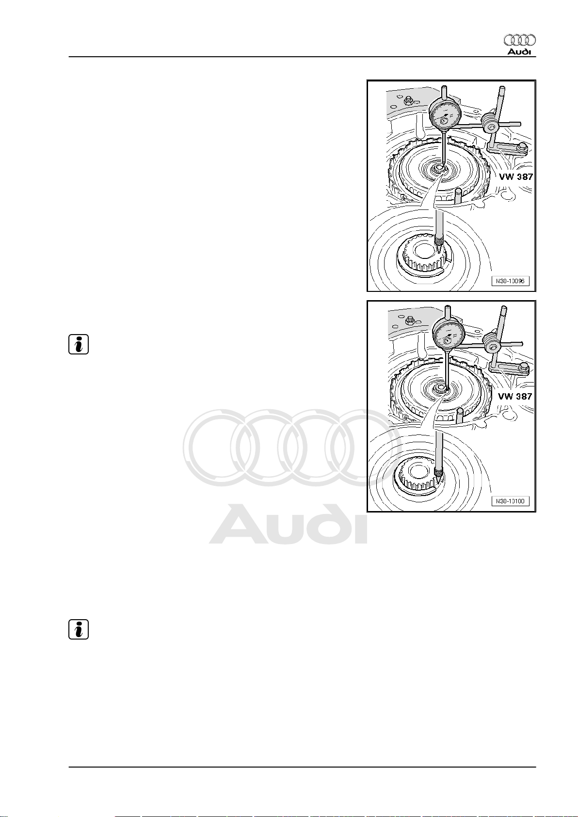
– Secure universal dial gauge bracket -VW 387- to gearbox
flange.
– For 1st measurement, apply tip of dial gauge to end of input
shaft as shown in illustration.
– Preload dial gauge to 2 mm and set to “0”.
– Lift up multiple clutch as far as it will go.
– Note reading on dial gauge (= axial clearance of input shaft).
– For 2nd measurement, apply tip of dial gauge to hub of inner
plate carrier as shown in illustration.
Audi TT 2007 ➤
Note
The tip of the dial gauge must not contact the circlip.
– Preload dial gauge to 2 mm and set to “0”.
– Lift up multiple clutch as far as it will go.
– Take reading and note down measured value.
The thickness of the new circlip is calculated according to the fol‐
lowing formula:
Circlip = 2nd measured value – 1st measured value + 1.85 (=
constant value)
The thickness of the new circlips is graduated in steps of 0.1 mm.
When selecting the required circlip, round up or down to the near‐
est 10th of a millimetre as required. In other words, values up to
0.049 are rounded down and values of 0.050 and above are roun‐
ded up.
Example:
♦ Calculated value for new circlip is 2.27 mm: round up to the
nearest 10th and select circlip with a thickness of 2.3 mm.
♦ Calculated value for new circlip is 2.24 mm: round down to the
nearest 10th and select circlip with a thickness of 2.2 mm.
Note
If the calculated thickness of the new circlip is exactly 2.0 mm, the
circlip fitted previously for taking the measurement does not have
to be removed.
1. Exploded view - servicing multiple clutch 23
Page 28
Protected by copyright. Copying for private or commercial purposes, in part or in whole, is not
permitted unless authorised by AUDI AG. AUDI AG does not guarantee or accept any liability
with respect to the correctness of information in this document. Copyright by AUDI AG.
Audi TT 2007 ➤
Direct shift gearbox 02E, four-wheel drive - Edition 08.2008
– Remove provisionally fitted circlip (2 mm) and fit new circlip
with thickness as calculated above.
Note
♦
Circlips must not be used more than once.
♦
The removed (provisional) circlip and all remaining circlips
should be disposed of.
– Install pump shaft. When installing, lift the shaft and turn it
slightly -arrow- so that it slides in and engages fully in the
splines.
– Install drive plate in multiple clutch.
• The projecting lug -arrow- on the drive plate must be posi‐
tioned between the colour-marked splines on the outer plate
carrier, or the marks made earlier in this procedure.
24 Rep. Gr.30 - Clutch
Page 29
Protected by copyright. Copying for private or commercial purposes, in part or in whole, is not
permitted unless authorised by AUDI AG. AUDI AG does not guarantee or accept any liability
with respect to the correctness of information in this document. Copyright by AUDI AG.
Direct shift gearbox 02E, four-wheel drive - Edition 08.2008
– Fit new circlip for drive plate.
• Installation position: the lug on the drive plate and the colourmarked splines on the outer plate carrier (or the corresponding
marks made previously) must be located between the ends of
the circlip.
– Using a screwdriver, check that circlip is fully engaged.
– Take out retaining pin -T10303- between multiple clutch and
housing.
Audi TT 2007 ➤
Caution
Leakage can occur at the contact surface of the clutch end
cover.
♦ Thoroughly degrease running surface -arrow- on drive
plate for internal seal of clutch end cover.
– Clean the contact surface for the outer seal of the clutch end
cover.
Caution
Leakage can occur at the internal seal for the clutch end cover.
♦ To ensure that the internal seal remains absolutely free of
grease, do not touch the seal with your hands.
– Take the clutch end cover out of its packaging, only taking hold
of it on the outside as illustrated.
– Clean end of gearbox shaft.
Note
♦
Using gear oil, lightly lubricate the outer seal for the clutch end
cover only.
♦
If there are any stickers on the inside or the outside of the
clutch end cover, remove them thoroughly.
1. Exploded view - servicing multiple clutch 25
Page 30
Protected by copyright. Copying for private or commercial purposes, in part or in whole, is not
permitted unless authorised by AUDI AG. AUDI AG does not guarantee or accept any liability
with respect to the correctness of information in this document. Copyright by AUDI AG.
Audi TT 2007 ➤
Direct shift gearbox 02E, four-wheel drive - Edition 08.2008
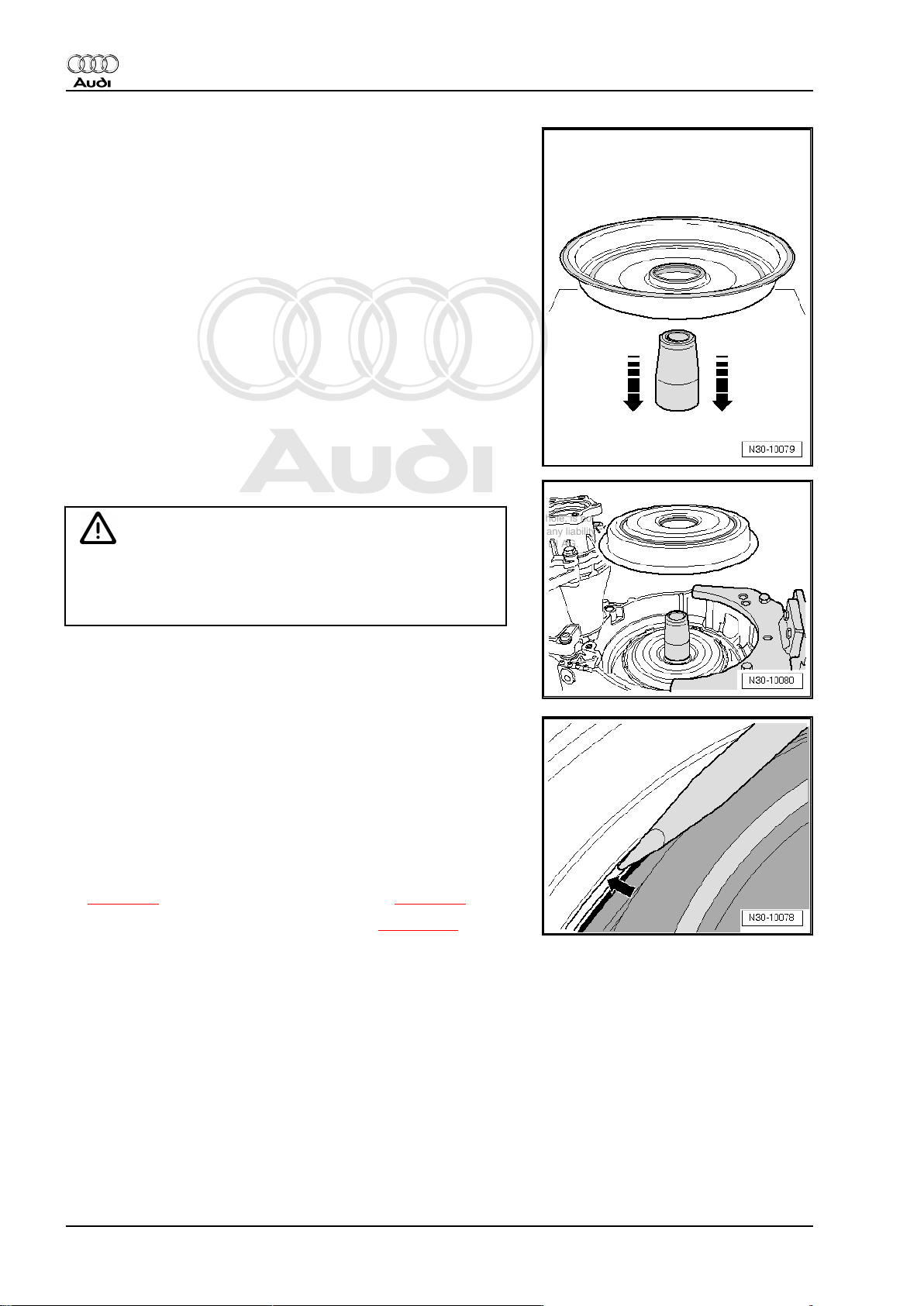
– Place assembly sleeve -T10302- on a flat surface.
– The internal seal in the new clutch end cover must be pre-
formed before installation; this is done by guiding the clutch
end cover, with the outside downwards, horizontally and uni‐
formly over the assembly sleeve -T10302- .
– Lift assembly sleeve -T10302- out of clutch end cover.
– Fit assembly sleeve -T10302- over end of multiple clutch shaft.
Caution
Clutch end cover can be damaged.
♦ Do not attempt to drive on the clutch end cover with a
hammer.
– Guide clutch end cover with the outside upwards horizontally
over assembly sleeve -T10302- and press cover uniformly on‐
to its seat.
– If necessary use a screwdriver to lever the clutch end cover
carefully into its seat as illustrated -arrow- so that the corru‐
gated ring can be fitted.
– Install corrugated ring for clutch end cover in gearbox housing,
always holding the ring in place on the opposite side so that it
remains in its groove.
– Using a screwdriver, check that corrugated ring is fully engag‐
ed.
– Install gearbox: vehicles with 2.0 ltr. TFSI engine
⇒ page 61 , vehicles with 3.2 ltr. MPI engine ⇒ page 74 .
– Fill up with gear oil for direct shift gearbox ⇒ page 100 .
– Connect vehicle diagnostic, testing and information system -
VAS 5051B- .
– Perform basic setting.
26 Rep. Gr.30 - Clutch
Page 31

Protected by copyright. Copying for private or commercial purposes, in part or in whole, is not
permitted unless authorised by AUDI AG. AUDI AG does not guarantee or accept any liability
with respect to the correctness of information in this document. Copyright by AUDI AG.
Direct shift gearbox 02E, four-wheel drive - Edition 08.2008
34 – Controls, housing
1 Electrical/electronic components and fit‐
ting locations
Diagnostic connector
Fitting location: The diagnostic connector is located below the
knee padding on the left side of the steering wheel.
Audi TT 2007 ➤
Selector lever lock solenoid -N110-
Fitting location: the selector lever lock solenoid -1- is located in
the selector mechanism.
The solenoid is integrated in the selector mechanism; it is there‐
fore not possible to renew only the solenoid on its own. It can only
be removed or installed together with the selector mechanism
⇒ page 44 .
Mechatronic unit for dual clutch gearbox -J743-
Fitting location: the mechatronic unit for dual clutch gearbox J743- is bolted to the front of the gearbox housing and covered
by the gearbox oil pan.
The control unit is an integrated component of the mechatronic
unit for dual clutch gearbox -J743- .
♦ Is checked via self-diagnosis
Removing and installing mechatronic unit for dual clutch gearbox
-J743- ⇒ page 121 .
1. 27
Page 32

Protected by copyright. Copying for private or commercial purposes, in part or in whole, is not
permitted unless authorised by AUDI AG. AUDI AG does not guarantee or accept any liability
with respect to the correctness of information in this document. Copyright by AUDI AG.
Audi TT 2007 ➤
Direct shift gearbox 02E, four-wheel drive - Edition 08.2008
Gearbox input speed sender -G182- / oil temperature sender for
multi-plate clutch -G509-
Fitting location: the gearbox input speed sender -G182- and
clutch temperature sender -G509- -item A- are bolted to the gear‐
box housing below the mechatronic unit for dual clutch gearbox J743- .
♦ Checked via self-diagnosis
Removing and installing gearbox input speed sender -G182- and
clutch temperature sender -G509- ⇒ page 125 .
Selector lever -E313- with tiptronic switch -F189- , switch for se‐
lector lever locked in position P -F319-
Fitting location: the selector lever -E313- with tiptronic switch F189- and switch for selector lever locked in position P -F319- is
integrated in the printed circuit -B- of the selector mechanism.
These components cannot be renewed separately.
♦ Checked via self-diagnosis
Selector lever -E313- with tiptronic switch -F189- and switch for
selector lever locked in position P -F319- can only be removed
and installed together with selector mechanism ⇒ page 44 .
Selector lever position display -Y6-
Fitting location: integrated into instrument cluster
Note
The selector lever position display can only be renewed together
with the instrument cluster.
If the selector lever position display flashes or lights up, please
refer to safety functions of gearbox control unit ⇒ page 9 .
Removing and installing instrument cluster ⇒ Rep. Gr. 90
Selector lever display illumination bulb -L101-
Fitting location: in trim for selector lever boot -1-.
♦ Is checked via self-diagnosis
Removing and installing selector lever display illumination bulb L101- ⇒ page 39
28 Rep. Gr.34 - Controls, housing
Page 33

Protected by copyright. Copying for private or commercial purposes, in part or in whole, is not
permitted unless authorised by AUDI AG. AUDI AG does not guarantee or accept any liability
with respect to the correctness of information in this document. Copyright by AUDI AG.
Direct shift gearbox 02E, four-wheel drive - Edition 08.2008
Brake light switch -F-
Fitting location: the brake light switch -arrow- is located on pedal
cluster.
♦ Is checked via self-diagnosis
Removing and installing brake light switch ⇒ Rep. Gr. 46
Note
To ensure a secure fit, the switch may only be fitted once.
Kickdown switch -F8-
An adapted value from accelerator position sender -G79- and ac‐
celerator position sender 2 -G185- (integrated in accelerator ped‐
al module) is stored in the engine control unit as the kickdown
signal.
♦ Is checked via self-diagnosis
♦ Signal is transmitted from engine control unit to gearbox con‐
trol unit via CAN bus.
Removing and installing accelerator pedal module ⇒ Rep. Gr.
20
Audi TT 2007 ➤
1. 29
Page 34

Protected by copyright. Copying for private or commercial purposes, in part or in whole, is not
permitted unless authorised by AUDI AG. AUDI AG does not guarantee or accept any liability
with respect to the correctness of information in this document. Copyright by AUDI AG.
Audi TT 2007 ➤
Direct shift gearbox 02E, four-wheel drive - Edition 08.2008
2 Exploded view - selector lever handle with interlock button (side), se‐
lector lever display illumination bulb -L101-
1 - Bolt
❑ 1 Nm
2 - Trim for selector lever boot
with selector lever display illu‐
mination bulb -L101-
❑ Removing and installing
⇒ page 39
3 - Guide
4 - Hose clip
❑ Removing and installing
⇒ “2.1 Removing and in‐
stalling selector lever
handle with interlock
button (side)”,
page 30
5 - Selector lever handle
❑ Removing and installing
⇒ page 30
2.1 Removing and installing selector lever handle with interlock button (side)
Special tools and workshop equipment required
♦ Hose clip pliers -V.A.G 1275-
30 Rep. Gr.34 - Controls, housing
Page 35

Protected by copyright. Copying for private or commercial purposes, in part or in whole, is not
permitted unless authorised by AUDI AG. AUDI AG does not guarantee or accept any liability
with respect to the correctness of information in this document. Copyright by AUDI AG.
Direct shift gearbox 02E, four-wheel drive - Edition 08.2008
♦ Cable tie
Removing
Note
The selector lever handle is removed together with the selector
lever boot.
– Apply handbrake.
– Shift selector lever into position “N”.
– Use a cable tie to secure the interlock button in pulled-out po‐
sition -arrow-, as shown in the illustration.
– Unclip selector lever boot on both sides and lift it off -arrows-.
Audi TT 2007 ➤
– Turn selector lever boot -2- inside out over selector lever han‐
dle -3-.
– Release hose clip -1-.
– Pull off selector lever handle together with selector lever boot
-arrow-, taking care not to touch interlock button.
2. Exploded view - selector lever handle with interlock button (side), selector lever display illumination bulb L101 31
Page 36

Protected by copyright. Copying for private or commercial purposes, in part or in whole, is not
permitted unless authorised by AUDI AG. AUDI AG does not guarantee or accept any liability
with respect to the correctness of information in this document. Copyright by AUDI AG.
Audi TT 2007 ➤
Direct shift gearbox 02E, four-wheel drive - Edition 08.2008
Installing
Installation is carried out in reverse sequence; note the following:
Note
♦
To install the selector lever handle, the interlock button must
be pulled out as far as it will go and secured with either a cable
tie -arrow- or with the assembly aid supplied with the new han‐
dle.
♦
If the interlock button was not secured, do not attempt to pull
it out of the selector lever handle using mechanical tools. In‐
stead, apply a compressed air gun to the bottom of the handle,
blow out the interlock button and secure it in this position.
– Push selector lever handle fully onto selector lever.
• The interlock button faces the driver.
• The handle must engage in the annular groove on the selector
lever.
– Remove cable tie or assembly aid.
• The interlock button mechanism should engage in the vertical
groove on the selector lever. If not, press the interlock button
into the selector lever handle.
– Bring hose clip -1- into correct position.
• The lug -arrow- on the hose clip faces front right.
– Clamp selector lever handle -2- on selector lever by tightening
hose clip with hose clip pliers -V.A.G 1275- .
– Clip retainer frame -3- for selector lever boot onto trim for se‐
lector lever boot.
32 Rep. Gr.34 - Controls, housing
Page 37

Protected by copyright. Copying for private or commercial purposes, in part or in whole, is not
permitted unless authorised by AUDI AG. AUDI AG does not guarantee or accept any liability
with respect to the correctness of information in this document. Copyright by AUDI AG.
Audi TT 2007 ➤
Direct shift gearbox 02E, four-wheel drive - Edition 08.2008
3 Exploded view - selector lever handle with interlock button (front), se‐
lector lever display illumination bulb -L101-
1 - Bolt
❑ 1 Nm
2 - Trim for selector lever boot
with selector lever display illu‐
mination bulb -L101-
❑ Removing and installing
⇒ page 39
3 - Guide
4 - Selector lever boot
❑ Detaching selector lever
boot from selector lever
handle ⇒ page 35
5 - Selector lever handle with
interlock button (front)
❑ ⇒ “3.1 Removing and in‐
stalling selector lever
handle with interlock
button (front)”,
page 33
❑ ⇒ “3.3 Moving interlock
button on selector lever
handle into installation
position”, page 37
3.1 Removing and installing selector lever handle with interlock button (front)
Removing
Note
The selector lever handle is removed together with the selector
lever boot.
– Apply handbrake.
– Shift selector lever into position “N”.
– Unclip selector lever boot on both sides and lift it off -arrows-.
3. Exploded view - selector lever handle with interlock button (front), selector lever display illumination bulb L101 33
Page 38

Protected by copyright. Copying for private or commercial purposes, in part or in whole, is not
permitted unless authorised by AUDI AG. AUDI AG does not guarantee or accept any liability
with respect to the correctness of information in this document. Copyright by AUDI AG.
Audi TT 2007 ➤
Direct shift gearbox 02E, four-wheel drive - Edition 08.2008
– Turn selector lever boot -2- inside out over selector lever han‐
dle -3-.
– Turn locking ring in direction of -arrow- as far as stop.
• Raised lug -b- on locking ring is misaligned from lug -a-.
Caution
Risk of damage to the selector mechanism.
Do not touch the interlock button -1- on the selector lever han‐
dle when pulling off the handle.
Otherwise the selector lever handle or the pull rod of the se‐
lector mechanism will be damaged when the handle is pulled
off.
– Pull off selector lever handle together with selector lever boot
upwards -arrow-, taking care not to touch interlock button -1-.
Installing
Installation is carried out in reverse sequence; note the following:
– Turn locking ring in direction of -arrow- as far as stop.
• Raised lug -b- on locking ring is misaligned from lug -a-.
• Interlock button faces direction of travel.
Caution
Risk of damage to the selector mechanism.
The interlock button -1- must protrude from the selector lever
handle during installation. If the interlock button was pressed
in by mistake when the handle was removed, the interlock but‐
ton must be moved back to its installation position
⇒ page 37 .
If the interlock button has been pressed in and the handle is
installed with the interlock button in this position, the handle
and the pull rod of the selector mechanism -3- will be damaged
irreparably.
– Carefully press selector lever handle fully into selector lever,
taking care not to touch interlock button -1-.
• The handle must engage in the annular groove on the selector
lever.
34 Rep. Gr.34 - Controls, housing
Page 39

Protected by copyright. Copying for private or commercial purposes, in part or in whole, is not
permitted unless authorised by AUDI AG. AUDI AG does not guarantee or accept any liability
with respect to the correctness of information in this document. Copyright by AUDI AG.
Direct shift gearbox 02E, four-wheel drive - Edition 08.2008
– Turn locking ring in direction of -arrow- as far as stop.
• It must be possible to turn the locking ring; press handle if
necessary.
• Lug -a- must align with raised lug -b- on locking ring.
Note
♦
The handle is not locked until the locking ring has been turned.
Only then can you press the interlock button on the handle.
♦
There may be increased resistance when you press the inter‐
lock button for the first time after installation.
– Press interlock button -1- on selector lever handle.
– Fold selector lever boot down and clip it in.
– Check selector mechanism ⇒ page 43 .
3.2 Detaching selector lever boot from se‐
lector lever handle
Audi TT 2007 ➤
Procedure:
– Remove selector lever handle ⇒ page 33 .
– Pull guide -1- off in direction of -arrow-.
3. Exploded view - selector lever handle with interlock button (front), selector lever display illumination bulb L101 35
Page 40

Protected by copyright. Copying for private or commercial purposes, in part or in whole, is not
permitted unless authorised by AUDI AG. AUDI AG does not guarantee or accept any liability
with respect to the correctness of information in this document. Copyright by AUDI AG.
Audi TT 2007 ➤
Direct shift gearbox 02E, four-wheel drive - Edition 08.2008
• Do not touch interlock button -A- when selector lever handle
has been removed.
– Hold upper end of selector lever boot -arrow 1-.
– Turn selector lever handle in direction of -arrow 2- and pull it
off -arrow 3-.
Installing selector lever boot with selector lever handle:
• Do not touch interlock button -A- when selector lever handle
has been removed.
– Insert selector lever handle in selector lever boot -arrow 1-
(with interlock button turned 90° out of position towards left).
– Hold upper end of selector lever boot -arrow 2-.
– Turn selector lever handle in direction of -arrow 3-.
– Clip guide -1- upwards into handle in opposite direction of
-arrow-.
– Install selector lever handle ⇒ page 33 .
36 Rep. Gr.34 - Controls, housing
Page 41

Protected by copyright. Copying for private or commercial purposes, in part or in whole, is not
permitted unless authorised by AUDI AG. AUDI AG does not guarantee or accept any liability
with respect to the correctness of information in this document. Copyright by AUDI AG.
Direct shift gearbox 02E, four-wheel drive - Edition 08.2008
3.3 Moving interlock button on selector lever handle into installation position
Special tools and workshop equipment required
♦ Release tool -T40203-
Selector lever handle with interlock button (front):
• Installation position: the interlock button -1- must protrude
from the selector lever handle.
If the interlock button has been pressed in, it must be moved back
into its installation position so that the selector lever handle can
be installed.
Audi TT 2007 ➤
– Carefully insert release tool -T40203- into selector lever han‐
dle -1- as far as stop.
Note
For illustration purposes, the handle is shown without selector
lever boot.
• Recess on release tool -T40203- should face interlock button,
hook should point towards left.
3. Exploded view - selector lever handle with interlock button (front), selector lever display illumination bulb L101 37
Page 42

Protected by copyright. Copying for private or commercial purposes, in part or in whole, is not
permitted unless authorised by AUDI AG. AUDI AG does not guarantee or accept any liability
with respect to the correctness of information in this document. Copyright by AUDI AG.
Audi TT 2007 ➤
Direct shift gearbox 02E, four-wheel drive - Edition 08.2008
– Hold selector lever handle -A- and turn release tool -T40203-
180° in direction of -arrow 1-.
– Hold handle and carefully pull out release tool -T40203-
-arrow 2-.
• When pulling out release tool -T40203- , interlock button -Aon selector lever handle is pressed out and locked in position.
• Do not touch interlock button on selector lever handle before
installing handle so that interlock button is not pressed in
again.
38 Rep. Gr.34 - Controls, housing
Page 43

Protected by copyright. Copying for private or commercial purposes, in part or in whole, is not
permitted unless authorised by AUDI AG. AUDI AG does not guarantee or accept any liability
with respect to the correctness of information in this document. Copyright by AUDI AG.
Direct shift gearbox 02E, four-wheel drive - Edition 08.2008
4 Removing and installing selector lev‐
er display illumination bulb -L101-
Special tools and workshop equipment required
♦ Removal wedge -3409-
Removing
– Apply handbrake.
– Shift selector lever into position “N”.
– Switch off ignition.
– Unclip selector lever boot on both sides and lift it off -arrows-.
Audi TT 2007 ➤
– Pull selector lever boot up and over handle.
– Using removal wedge -3409- , pry trim panel for centre console
out of centre console -arrows-.
– Unplug electrical connectors and remove trim panel for centre
console.
4. Removing and installing selector lever display illumination bulb L101 39
Page 44

Protected by copyright. Copying for private or commercial purposes, in part or in whole, is not
permitted unless authorised by AUDI AG. AUDI AG does not guarantee or accept any liability
with respect to the correctness of information in this document. Copyright by AUDI AG.
Audi TT 2007 ➤
Direct shift gearbox 02E, four-wheel drive - Edition 08.2008
– Remove bolts -arrows- and detach trim for selector lever boot
-1- together with selector lever display illumination bulb L101- .
Installing
Installation is carried out in reverse sequence; note the following:
Tightening torques:
• ⇒ “2 Exploded view - selector lever handle with interlock button
(side), selector lever display illumination bulb L101 ”,
page 30
• ⇒ “3 Exploded view - selector lever handle with interlock button
(front), selector lever display illumination bulb L101 ”,
page 33
– Make sure trim panel engages audibly in centre console.
40 Rep. Gr.34 - Controls, housing
Page 45

Protected by copyright. Copying for private or commercial purposes, in part or in whole, is not
permitted unless authorised by AUDI AG. AUDI AG does not guarantee or accept any liability
with respect to the correctness of information in this document. Copyright by AUDI AG.
Audi TT 2007 ➤
Direct shift gearbox 02E, four-wheel drive - Edition 08.2008
5 Exploded view - selector mechanism
Note
Lubricate all bearings and moving surfaces with polycarbamide grease ⇒ Electronic parts catalogue .
1 - Support bracket
❑ For selector lever cable
2 - Bolt
❑ 20 Nm and then turn 90°
further
❑ 2x
❑ Renew
3 - Securing clip
❑ Renew
4 - Bolt
❑ 13 Nm
5 - Locking plate
❑ Renew
6 - Selector lever cable
❑ Do not bend or kink
❑ Do not grease cable eye
❑ Renew selector lever
cable if sleeves are
damaged
❑ Removing and installing
⇒ page 46
❑ Adjusting ⇒ page 50
7 - Nut
❑ 8 Nm
❑ 4x
❑ Selector mechanism to
body
8 - Buffer stop for selector lever
❑ Clipped onto selector
mechanism
9 - Shift unit
❑ With integrated printed circuit for selector mechanism ( selector lever -E313- )
Caution
Electronic components
of selector mechanism
can be damaged by elec‐
trostatic discharge.
♦Do not touch printed cir‐
cuit with bare hands.
❑ Incorporates tiptronic switch -F189- and selector lever lock solenoid -N110❑ Tiptronic switch -F189- and selector lever lock solenoid -N110- can be checked via “Guided Fault Finding”
⇒ Vehicle diagnosis, testing and information system VAS 5051
5. Exploded view - selector mechanism 41
Page 46

Protected by copyright. Copying for private or commercial purposes, in part or in whole, is not
permitted unless authorised by AUDI AG. AUDI AG does not guarantee or accept any liability
with respect to the correctness of information in this document. Copyright by AUDI AG.
Audi TT 2007 ➤
Direct shift gearbox 02E, four-wheel drive - Edition 08.2008
❑ If tiptronic switch -F189- or selector lever lock solenoid -N110- are defective, renew shift unit
❑ Manual release of selector mechanism ⇒ page 42
❑ Removing and installing ⇒ page 51
10 - Detent spring
11 - Bolt
❑ 3.5 Nm
12 - Pivot pin
13 - Bolt
❑ 3.5 Nm
❑ 4x
14 - Detent plate
15 - Cover for shift unit
❑ With glued-on gasket
16 - Nut
❑ 9 Nm
❑ 4x
❑ Self-locking
❑ Renew
17 - Bracket
18 - Lock washer
❑ 2x
19 - Locking plate
❑ For selector lever cable
❑ Renew
❑ Installation position: angled end points towards shift unit
5.1 Manual release of selector mechanism
In the event of failure of the supply voltage to the selector lever
lock solenoid (discharged battery or defective fuse), or if the sol‐
enoid itself is defective, the selector lever cannot be shifted out
of position “P”. The vehicle then cannot be moved because the
parking lock is engaged.
– Check fuses ⇒ Current flow diagrams, Electrical fault finding
and Fitting locations.
– Check battery voltage ⇒ Electrical system; General informa‐
tion; Rep. Gr. 27 .
– If no fault is found in the supply voltage, release the selector
mechanism manually as follows:
– Unclip selector lever boot on both sides and lift it off -arrows-.
– Pull selector lever boot up and over handle.
42 Rep. Gr.34 - Controls, housing
Page 47

Protected by copyright. Copying for private or commercial purposes, in part or in whole, is not
permitted unless authorised by AUDI AG. AUDI AG does not guarantee or accept any liability
with respect to the correctness of information in this document. Copyright by AUDI AG.
Direct shift gearbox 02E, four-wheel drive - Edition 08.2008
– Release selector lever lock solenoid -A- by pressing lever
-B- inwards -arrow- with a screwdriver -1- and holding it in this
position.
• The solenoid will then release the selector lever.
– Now press button on selector lever handle and shift selector
lever out of “P”.
Note
However, if the selector lever is now moved back to “P”, the se‐
lector lever lock solenoid will again lock it mechanically in position
“P” and it will have to be released once again.
5.2 Checking selector mechanism and igni‐
tion key removal lock
Audi TT 2007 ➤
♦ It should not be possible to operate the starter while the se‐
lector lever is in position “S”, “D” or “R” or in the tiptronic
position.
♦ If the selector lever is moved into position “N” while the vehicle
is rolling at a speed above 5 km/h, the solenoid for the selector
lever lock must not engage and block the selector lever. The
selector lever can be shifted into a driving gear.
♦ If the selector lever is moved into position “N” while the vehicle
is rolling at a speed below 5 km/h (almost at a standstill), the
solenoid for the selector lever lock should only engage after a
delay of approx. one second. The selector lever cannot be
shifted out of position “N” until brake pedal is depressed.
Selector lever in position “P” and ignition switched off:
The ignition key can be removed.
Selector lever in any position other than “P” and ignition switched
off:
The ignition key cannot be removed.
Selector lever in position “P”, button on selector lever pressed in
and ignition switched on:
• Brake pedal not depressed:
The selector lever is locked with the button pressed in, and cannot
be shifted out of position “P”. The solenoid for selector lever lock
blocks the selector lever.
• Brake pedal depressed:
The solenoid for selector lever lock releases the selector lever
and a gear can be engaged. Shift the selector lever slowly from
position “P” through “R, N, D and S” and check whether the dis‐
play in the instrument cluster shows the correct selector lever
position in each case.
Selector lever in position “N”, button on selector lever pressed in
and ignition switched on:
• Brake pedal not depressed:
5. Exploded view - selector mechanism 43
Page 48

Protected by copyright. Copying for private or commercial purposes, in part or in whole, is not
permitted unless authorised by AUDI AG. AUDI AG does not guarantee or accept any liability
with respect to the correctness of information in this document. Copyright by AUDI AG.
Audi TT 2007 ➤
Direct shift gearbox 02E, four-wheel drive - Edition 08.2008
The selector lever is locked and cannot be shifted out of position
“N”. The solenoid for selector lever lock blocks the selector lever.
• Brake pedal depressed:
The solenoid for selector lever lock releases the selector lever
and a gear can be engaged.
Note
♦
If you depress the brake pedal you can shift from “N” to “D”
without pressing the button on the selector lever.
♦
However, to shift from “N” to “R” you do have to additionally
press the button on the selector lever.
Selector lever in position “D”, ignition switched on:
The selector lever is locked and cannot be shifted from “D” to “S”.
• Press button on selector lever:
The selector lever is released and can be shifted from “D” to “S”.
Selector lever in position “D”, ignition and lights switched on:
• Shift selector lever into tiptronic gate:
The illuminated “D” symbol in the selector lever position display
should go out and the “+” and “–” symbols should light up.
The selector lever position display in the instrument cluster should
switch from “PRNDS” to “654321” when the selector lever is
moved into the tiptronic gate.
• Move the selector lever in the tiptronic gate to “+” and “–”.
When you move the selector lever to “+” or “–”, the display
“654321” in the instrument cluster should move one gear up or
down accordingly.
– If the selector mechanism or the ignition key removal lock does
not operate as described, connect vehicle diagnostic, testing
and information system -VAS 5051B- .
– “Interrogate fault memory - all fault menus”, trace and elimi‐
nate any faults displayed via “Guided Fault Finding”.
5.3 Removing and installing selector mech‐
anism
Removing
– Shift selector lever into position “P”.
– Switch off ignition.
– Remove selector lever handle ⇒ page 30 .
– Remove trim panel for centre console ⇒ Rep. Gr. 68 .
– Remove ashtray ⇒ Rep. Gr. 68 .
44 Rep. Gr.34 - Controls, housing
Page 49

Protected by copyright. Copying for private or commercial purposes, in part or in whole, is not
permitted unless authorised by AUDI AG. AUDI AG does not guarantee or accept any liability
with respect to the correctness of information in this document. Copyright by AUDI AG.
Direct shift gearbox 02E, four-wheel drive - Edition 08.2008
– Unplug electrical connector -A-.
Note
-Items 1, B, C- can be disregarded.
– Remove air cleaner housing (top and bottom sections) ⇒ Rep.
Gr. 24 .
– Detach locking plate -C-.
– Press securing clip -A- upwards and detach.
– Press selector lever cable off selector shaft lever -arrow- and
pull out of support bracket -D-.
Note
Audi TT 2007 ➤
♦
Do not bend or kink the selector lever cable.
♦
-Items 1 and B- can be disregarded.
– Remove noise insulation: front -1- and rear -2- ⇒ Rep. Gr.
66 .
– Remove exhaust system ⇒ Rep. Gr. 26 .
– Remove propshaft ⇒ Rear final drive 02D and 0AV; Rep. Gr.
39 .
– Remove heat shield -arrows-.
5. Exploded view - selector mechanism 45
Page 50

Protected by copyright. Copying for private or commercial purposes, in part or in whole, is not
permitted unless authorised by AUDI AG. AUDI AG does not guarantee or accept any liability
with respect to the correctness of information in this document. Copyright by AUDI AG.
Audi TT 2007 ➤
Direct shift gearbox 02E, four-wheel drive - Edition 08.2008
Note
A second mechanic is required to help detach the selector mech‐
anism under the vehicle.
– Unscrew nuts -arrows- (from above).
Note
-Items 1 and 2- can be disregarded.
– Detach selector mechanism together with selector lever cable
from below.
Note
♦
Do not bend or kink the selector lever cable.
♦
It is also possible to remove the selector mechanism without
the selector lever cable; to do so, you first have to detach the
selector lever cable from the shift unit
⇒ “5.4 Removing and installing selector lever cable”,
page 46 .
Installing
• Tightening torques ⇒ page 41
Installation is carried out in reverse sequence; note the following:
Note
♦
Renew locking plate and securing clip for selector lever cable.
♦
Do not bend or kink the selector lever cable.
– Install heat shield ⇒ Rep. Gr. 66 .
– Install propshaft ⇒ Rear final drive 02D and 0AV; Rep. Gr.
39 .
– Install exhaust system and perform stress-free alignment ⇒
Rep. Gr. 26 .
– Install ashtray ⇒ Rep. Gr. 68 .
– Install trim panel for centre console ⇒ Rep. Gr. 68 .
– Install selector lever handle ⇒ page 30 .
– Adjust selector lever cable ⇒ page 50 .
– Check selector mechanism and ignition key removal lock
⇒ page 43 .
– Install noise insulation ⇒ Rep. Gr. 66 .
5.4 Removing and installing selector lever cable
Removing
– Shift selector lever into position “P”.
– Switch off ignition.
46 Rep. Gr.34 - Controls, housing
Page 51

Protected by copyright. Copying for private or commercial purposes, in part or in whole, is not
permitted unless authorised by AUDI AG. AUDI AG does not guarantee or accept any liability
with respect to the correctness of information in this document. Copyright by AUDI AG.
Direct shift gearbox 02E, four-wheel drive - Edition 08.2008
– Remove air cleaner housing (top and bottom sections) ⇒ Rep.
Gr. 24 .
– Detach locking plate -C-.
– Press securing clip -A- upwards and detach.
– Press selector lever cable off selector shaft lever -arrow- and
pull out of support bracket -D-.
Note
♦
Do not bend or kink the selector lever cable.
♦
-Items 1 and B- can be disregarded.
– Remove noise insulation: front -1- and rear -2- ⇒ Rep. Gr.
66 .
– Remove exhaust system ⇒ Rep. Gr. 26 .
– Remove propshaft ⇒ Rear final drive 02D and 0AV; Rep. Gr.
39 .
Audi TT 2007 ➤
– Remove heat shield -arrows-.
– Detach cover for shift unit -arrows-.
– Carefully slide cover for shift unit together with sleeve along
selector lever cable towards front of vehicle, taking care not to
damage sleeve.
5. Exploded view - selector mechanism 47
Page 52

Protected by copyright. Copying for private or commercial purposes, in part or in whole, is not
permitted unless authorised by AUDI AG. AUDI AG does not guarantee or accept any liability
with respect to the correctness of information in this document. Copyright by AUDI AG.
Audi TT 2007 ➤
Direct shift gearbox 02E, four-wheel drive - Edition 08.2008
Caution
Electronic components of selector mechanism can be dam‐
aged by electrostatic discharge.
♦ Do not touch printed circuit -B- with bare hands.
– Touch vehicle earth with your hand (without gloves) to dis‐
charge any static electricity.
– Remove bolts -arrows-.
– Unclip retaining tabs on both sides and detach detent plate
-A- from shift unit.
– Shift selector lever to position “S”.
– Pull down locking plate -1- for selector lever cable and remove.
– Pull plastic retaining spring -2- forwards slightly and press piv‐
ot pin -3- upwards only as far as necessary -arrow-.
Note
Ensure that pin is not pressed out completely.
– Pull selector lever cable -4- out of shift unit.
Note
Do not bend or kink the selector lever cable.
Installing
• Tightening torques ⇒ page 41
Installation is carried out in reverse sequence; note the following:
Note
♦
Renew locking plates and securing clip for selector lever ca‐
ble.
♦
The selector lever cable must be renewed if the sleeves are
damaged.
48 Rep. Gr.34 - Controls, housing
Page 53

Protected by copyright. Copying for private or commercial purposes, in part or in whole, is not
permitted unless authorised by AUDI AG. AUDI AG does not guarantee or accept any liability
with respect to the correctness of information in this document. Copyright by AUDI AG.
Direct shift gearbox 02E, four-wheel drive - Edition 08.2008
– Guide selector lever cable into cover for shift unit, taking care
not to damage sleeve.
– Engage sleeve in cover for shift unit.
Note
Check that the sleeve is seated correctly and not twisted.
– Insert end of selector lever cable -4- into joint on selector lever.
– Press pivot pin -3- downwards -arrow-.
• The plastic securing spring -2- should lock the pin in position.
– Secure selector lever cable to shift unit using new locking plate
-1-.
• Installation position: angled end of locking plate faces shift
unit.
Caution
Audi TT 2007 ➤
Electronic components of selector mechanism can be dam‐
aged by electrostatic discharge.
♦ Do not touch printed circuit -B- with bare hands.
– Touch vehicle earth with your hand (without gloves) to dis‐
charge any static electricity.
– Clip detent plate -A- into position on both sides.
– Tighten bolts -arrows-.
– Hand-tighten cover for shift unit (with glued-on seal) to shift
unit -arrows-, making sure that seal is seated correctly.
– Fit sleeve for selector lever cable in cover for shift unit.
5. Exploded view - selector mechanism 49
Page 54

Protected by copyright. Copying for private or commercial purposes, in part or in whole, is not
permitted unless authorised by AUDI AG. AUDI AG does not guarantee or accept any liability
with respect to the correctness of information in this document. Copyright by AUDI AG.
Audi TT 2007 ➤
Direct shift gearbox 02E, four-wheel drive - Edition 08.2008
– Press selector lever cable onto selector shaft lever on gearbox
in opposite direction of -arrow-.
– Fit securing clip -A- and press downwards to secure.
– Install locking plate -C-.
– Move selector lever from “S” to “P”.
Note
♦
Check that selector lever moves freely.
♦
If the selector mechanism is stiff, renew the selector lever ca‐
ble or service the selector mechanism.
– Secure cover for shift unit -arrows-.
– Install heat shield ⇒ Rep. Gr. 66 .
– Install propshaft ⇒ Rear final drive 02D and 0AV; Rep. Gr.
39 .
– Install exhaust system and perform stress-free alignment ⇒
Rep. Gr. 26 .
– Adjust selector lever cable ⇒ page 50 .
– Check selector mechanism ⇒ page 43 .
– Install noise insulation ⇒ Rep. Gr. 66 .
5.5 Adjusting selector lever cable
Procedure
– Remove air cleaner housing (top and bottom sections) ⇒ Rep.
Gr. 24 .
50 Rep. Gr.34 - Controls, housing
Page 55

Protected by copyright. Copying for private or commercial purposes, in part or in whole, is not
permitted unless authorised by AUDI AG. AUDI AG does not guarantee or accept any liability
with respect to the correctness of information in this document. Copyright by AUDI AG.
Direct shift gearbox 02E, four-wheel drive - Edition 08.2008
• Selector mechanism and selector lever cable operate smooth‐
ly when changing gears.
• Sleeve on selector lever cable is undamaged.
• Securing clip -A- is fitted correctly (pressed down and locked).
Note
♦
If the selector mechanism is stiff, renew the selector lever ca‐
ble or service the selector mechanism.
♦
The selector lever cable must be renewed if a sleeve is dam‐
aged.
– Shift selector lever into position “P”.
– Slacken bolt -B-.
– Set selector shaft lever on gearbox to position “P”.
– Push vehicle forwards until wheels lock so that detent lever in
gearbox engages in parking lock gear.
– To release tension in selector lever cable, carefully move se‐
lector lever slightly forwards and backwards, without shifting
into a different position.
– Tighten bolt -B-, taking care not to alter position of selector
lever cable. Tightening torque ⇒ page 41
Checking adjustment of selector lever cable
– Keep button pressed, while pulling selector lever approx. 5
mm to the rear out of position “P”. Then keep lever in this po‐
sition, do not move it into “R”.
– Release selector lever.
• The selector lever should spring back into position “P” by itself.
– Shift selector lever into position “N”.
– Keep button pressed, while pulling selector lever approx. 5
mm to the rear out of position “N”. Then keep lever in this po‐
sition, do not move it into “D”.
– Release selector lever.
• The selector lever should spring back into position “N” by itself.
– Keep button pressed, while pushing selector lever approx. 5
mm to the front out of position “N”. Then keep lever in this
position, do not move it into “R”.
Audi TT 2007 ➤
– Release selector lever.
• The selector lever should spring back into position “N” by itself.
– Repeat the adjustment if the selector lever does not react as
described.
– Check selector mechanism ⇒ page 43 .
5.6 Removing and installing tiptronic switch
-F189-
The tiptronic switch -F189- is integrated in the selector mecha‐
nism; it cannot be renewed separately.
5. Exploded view - selector mechanism 51
Page 56

Protected by copyright. Copying for private or commercial purposes, in part or in whole, is not
permitted unless authorised by AUDI AG. AUDI AG does not guarantee or accept any liability
with respect to the correctness of information in this document. Copyright by AUDI AG.
Audi TT 2007 ➤
Direct shift gearbox 02E, four-wheel drive - Edition 08.2008
Note
The selector mechanism has to be renewed if the tiptronic switch
-F189- is defective ⇒ page 44 .
5.7 Removing and installing selector lever lock solenoid -N110-
The selector lever lock solenoid -N110- is integrated in the se‐
lector mechanism; it cannot be renewed separately.
Note
The selector mechanism has to be renewed if the selector lever
lock solenoid -N110- is defective ⇒ page 44 .
5.8 Checking connectors on selector mech‐
anism
Proceed as follows if malfunctions occur in the selector mecha‐
nism:
– Connect vehicle diagnostic, testing and information system -
VAS 5051B- .
– “Interrogate fault memory - all fault menus”, trace and elimi‐
nate any faults displayed via “Guided Fault Finding”.
A - 10-pin connector for wiring from selector mechanism to gear‐
box (with CAN wires)
B - 4-pin connector for wiring to selector lever lock solenoid N110- and selector lever locked in position P switch -F319-
C - 10-pin connector for wiring to cover of selector mechanism
52 Rep. Gr.34 - Controls, housing
Page 57

Protected by copyright. Copying for private or commercial purposes, in part or in whole, is not
permitted unless authorised by AUDI AG. AUDI AG does not guarantee or accept any liability
with respect to the correctness of information in this document. Copyright by AUDI AG.
Direct shift gearbox 02E, four-wheel drive - Edition 08.2008
6 Overview - removing and installing
gearbox
♦ ⇒ “6.1 Removing gearbox - vehicles with 2.0 ltr. TFSI engine”,
page 53
♦ ⇒ “6.2 Installing gearbox - vehicles with 2.0 ltr. TFSI engine”,
page 61
♦ ⇒ “6.3 Removing gearbox - vehicles with 3.2 ltr. MPI engine”,
page 66
♦ ⇒ “6.4 Installing gearbox - vehicles with 3.2 ltr. MPI engine”,
page 74
6.1 Removing gearbox - vehicles with 2.0 ltr. TFSI engine
♦ Hose clamps, up to 25 mm
-3094-
♦ Gearbox support -3282-
♦ Pin -3282/29-
♦ Adjustment plate -3282/42
A-
♦ Engine and gearbox jack -
V.A.G 1383 A-
Audi TT 2007 ➤
6. Overview - removing and installing gearbox 53
Page 58

Protected by copyright. Copying for private or commercial purposes, in part or in whole, is not
permitted unless authorised by AUDI AG. AUDI AG does not guarantee or accept any liability
with respect to the correctness of information in this document. Copyright by AUDI AG.
Audi TT 2007 ➤
Direct shift gearbox 02E, four-wheel drive - Edition 08.2008
♦ Support bracket -10 - 222 A-
♦ Hooks -10 - 222 A /10-
♦ Extension -2024 A /1-
♦ Engine bung set -VAS 6122-
Procedure
Note
♦
Observe general repair instructions ⇒ page 11 .
♦
Observe rules for cleanliness when working on the gearbox
⇒ page 14 .
♦
Observe notes on direct shift gearbox 02E ⇒ page 8 .
♦
All cable ties which are released or cut open during removal
must be fitted in the same position when installing.
– Shift selector lever into position “P”.
54 Rep. Gr.34 - Controls, housing
Page 59

Protected by copyright. Copying for private or commercial purposes, in part or in whole, is not
permitted unless authorised by AUDI AG. AUDI AG does not guarantee or accept any liability
with respect to the correctness of information in this document. Copyright by AUDI AG.
Direct shift gearbox 02E, four-wheel drive - Edition 08.2008
Caution
When disconnecting the battery there is a risk of serious dam‐
age to electronic components:
♦ Observe the correct procedure for disconnecting the bat‐
tery.
– With the ignition switched off, disconnect battery earth cable
⇒ Rep. Gr. 27 .
– Remove front exhaust pipe with catalytic converters and front
silencer ⇒ Rep. Gr. 26 .
– Remove radiator cowl ⇒ Rep. Gr. 19 .
– Remove starter ⇒ Rep. Gr. 27 .
– Remove both front wheels.
– Remove bolts -arrows- and detach bracket for air cleaner
housing.
Audi TT 2007 ➤
– Disconnect earth wire -3-.
Caution
The control unit (mechatronic unit) can be damaged by elec‐
trostatic discharge.
♦ Do not touch contact pins in gearbox connector with bare
hands.
– Touch vehicle earth with your hand (without gloves) to dis‐
charge any static electricity.
– Turn fastener anti-clockwise and unplug electrical connector
-4- on gearbox.
Note
-Items 1, 2- and -arrow- can be disregarded.
6. Overview - removing and installing gearbox 55
Page 60

Protected by copyright. Copying for private or commercial purposes, in part or in whole, is not
permitted unless authorised by AUDI AG. AUDI AG does not guarantee or accept any liability
with respect to the correctness of information in this document. Copyright by AUDI AG.
Audi TT 2007 ➤
Direct shift gearbox 02E, four-wheel drive - Edition 08.2008
– Clamp off coolant hoses at gearbox oil cooler with hose
clamps -3094- and disconnect hoses from gear oil cooler -A-.
Note
Seal off open lines and connections with clean plugs or sealing
caps to prevent dirt from entering.
– Move wiring harnesses -arrows- clear and disengage electri‐
cal connector -1- at bracket.
– Remove all engine/gearbox securing bolts which are accessi‐
ble from above.
Note
Bolt -item 3- is located in aperture for starter.
– Set up support bracket -10 - 222 A- on body flanges.
– Hook spindle of support bracket into engine lifting eye (left-
side).
– Take up weight of engine with spindle; do not lift.
56 Rep. Gr.34 - Controls, housing
Page 61

Protected by copyright. Copying for private or commercial purposes, in part or in whole, is not
permitted unless authorised by AUDI AG. AUDI AG does not guarantee or accept any liability
with respect to the correctness of information in this document. Copyright by AUDI AG.
Direct shift gearbox 02E, four-wheel drive - Edition 08.2008
– Remove noise insulation (front) -1- ⇒ Rep. Gr. 66 .
– Remove noise insulation frame -arrow - and noise insulation
(rear) ⇒ Rep. Gr. 66 .
Audi TT 2007 ➤
– Remove noise insulation (left-side) -arrows-.
– Release hose clips -1- and -2- and remove air intake pipe.
6. Overview - removing and installing gearbox 57
Page 62

Protected by copyright. Copying for private or commercial purposes, in part or in whole, is not
permitted unless authorised by AUDI AG. AUDI AG does not guarantee or accept any liability
with respect to the correctness of information in this document. Copyright by AUDI AG.
Audi TT 2007 ➤
Direct shift gearbox 02E, four-wheel drive - Edition 08.2008
– Unbolt heat shield for drive shaft (right-side) from bevel box
-arrows-.
– Unbolt drive shaft (left-side) from gearbox flange.
– Unbolt drive shaft (right-side) from bevel box flange.
For vehicles equipped with front left vehicle level sender -G78-
– Unscrew bolt -1- at front left vehicle level sender -G78- .
Note
♦
-Items 2 and 3- can be disregarded.
♦
On vehicles with “Audi magnetic ride (AMR)” a front right ve‐
hicle lever sender -G289- may also be fitted on the right side
of the vehicle. Proceed with it in the same manner as with the
front left vehicle level sender -G78- .
All vehicles:
– Mark installation position of nuts -arrows- on both sides with a
felt-tip pen.
– Remove nuts -arrows- securing swivel joint on both sides ⇒
Rep. Gr. 40 .
– Disengage swivel joints from wishbones.
– Swivel suspension strut (left-side) outwards and support with
extension -2024 A /1- as shown in illustration.
WARNING
Risk of accident if parts of support are not properly secured.
♦ Secure locking pin and wishbone with retaining clip
-arrow- and nut -1-.
– Repeat procedure on right side of vehicle.
58 Rep. Gr.34 - Controls, housing
Page 63

Protected by copyright. Copying for private or commercial purposes, in part or in whole, is not
permitted unless authorised by AUDI AG. AUDI AG does not guarantee or accept any liability
with respect to the correctness of information in this document. Copyright by AUDI AG.
Direct shift gearbox 02E, four-wheel drive - Edition 08.2008
– Remove bolts -1- for support bracket.
– Pull off securing clip -3- -arrow- and detach selector lever ca‐
ble from gearbox.
Note
-Item 2- can be disregarded.
Caution
Risk of damage to seal in propshaft flange.
♦ Slackening off bolts for pendulum support/subframe cau‐
ses engine/gearbox assembly to swing forwards slightly.
Audi TT 2007 ➤
– Remove bolts -1, 2, 3- and detach pendulum support.
– Unplug electrical connector -1- at oil level and oil temperature
sender -G266- .
– Unclip bracket -2- for electrical wiring leading to oil level and
oil temperature sender -G266- at subframe.
– Slacken bolts -1- and remove bolts -2-.
6. Overview - removing and installing gearbox 59
Page 64

Protected by copyright. Copying for private or commercial purposes, in part or in whole, is not
permitted unless authorised by AUDI AG. AUDI AG does not guarantee or accept any liability
with respect to the correctness of information in this document. Copyright by AUDI AG.
Audi TT 2007 ➤
Direct shift gearbox 02E, four-wheel drive - Edition 08.2008
– Remove bolts -1- and -2- and detach gearbox support -A-.
– Lower engine/gearbox assembly using spindle of support
bracket -10 - 222 A- until distance -a- is obtained between
gearbox housing and gearbox mounting.
• Dimension -a- = 100 ... 110 mm
– Remove bolt -1- and move bracket with coolant hose -arrow-
to side.
60 Rep. Gr.34 - Controls, housing
Page 65

Protected by copyright. Copying for private or commercial purposes, in part or in whole, is not
permitted unless authorised by AUDI AG. AUDI AG does not guarantee or accept any liability
with respect to the correctness of information in this document. Copyright by AUDI AG.
Direct shift gearbox 02E, four-wheel drive - Edition 08.2008
To remove the direct shift gearbox 02E, set up gearbox support
-3282- with adjustment plate -3282/42A- and place on engine and
gearbox jack -V.A.G 1383 A- .
– Align arms of gearbox support according to holes in adjust‐
ment plate -3282/42A- .
– Secure support elements as illustrated on adjustment plate
-3282/42A- . However, use “retainer plate with drilling” as front
support element.
– Place engine and gearbox jack -V.A.G 1383 A- underneath
vehicle.
• The arrow symbol on the adjustment plate points in the direc‐
tion of travel.
– Align gearbox support -3282- parallel with gearbox.
– Screw pin -3282/29- into gearbox.
– Secure “retainer plate with drilling” firmly to gearbox as illus‐
trated -arrow-.
– Insert last support element in gearbox as illustrated.
– Support gearbox by lifting from underneath with engine and
gearbox jack -V.A.G 1383 A- .
– Remove remaining engine/gearbox securing bolts.
– Press gearbox off dowel sleeves.
– Carefully lower gearbox using engine and gearbox jack -V.A.G
1383 A- , taking care not to trap wiring or other connections.
– While lowering gearbox, change position of gearbox using
spindles on gearbox support -3282- .
Audi TT 2007 ➤
6.2 Installing gearbox - vehicles with 2.0 ltr.
TFSI engine
Procedure
Installation is carried out in reverse sequence; note the following:
Note
♦
Renew bolts which are tightened by turning through a speci‐
fied angle.
♦
Renew seals, gaskets and self-locking bolts and nuts.
♦
Renew locking plate and securing clip for selector lever cable.
♦
Hose connections and air pipes and hoses must be free from
oil and grease before fitting.
♦
Secure all hose connections with the correct hose clips (as
original equipment); refer to ⇒ Electronic parts catalogue .
♦
To ensure that the charge air hoses can be connected se‐
curely, you must spray the screws on used screw-type clips
with rust remover prior to installation.
♦
Re-attach all cable ties at the same locations when re-instal‐
ling.
• Tightening torques ⇒ page 65
– Check needle bearing in crankshaft ⇒ Rep. Gr. 13 .
– Clean splines of input shaft and hub; remove corrosion.
6. Overview - removing and installing gearbox 61
Page 66

Protected by copyright. Copying for private or commercial purposes, in part or in whole, is not
permitted unless authorised by AUDI AG. AUDI AG does not guarantee or accept any liability
with respect to the correctness of information in this document. Copyright by AUDI AG.
Audi TT 2007 ➤
Direct shift gearbox 02E, four-wheel drive - Edition 08.2008
– Grease splines with a very small amount of grease for clutch
plate splines; for grease for clutch plate splines refer to ⇒
Electronic parts catalogue . It is important to remove excess
grease.
– Check that dowel sleeves -A- are correctly seated in cylinder
block.
– Carefully raise gearbox using engine and gearbox jack -V.A.G
1383 A- and position correctly using gearbox support -3282- .
– Join gearbox to engine, taking care not to trap wiring or other
connections.
– Secure gearbox to engine.
Note
Bolt -item 3- is only accessible through opening of removed start‐
er.
62 Rep. Gr.34 - Controls, housing
Page 67

Protected by copyright. Copying for private or commercial purposes, in part or in whole, is not
permitted unless authorised by AUDI AG. AUDI AG does not guarantee or accept any liability
with respect to the correctness of information in this document. Copyright by AUDI AG.
Direct shift gearbox 02E, four-wheel drive - Edition 08.2008
– Install assembly mountings (note correct sequence)
⇒ page 85 .
WARNING
Do not remove support bracket -10-222 A- until all bolts for the
assembly mounting have been tightened to specified torque
and the subframe is installed.
– Detach gearbox support -3282- from gearbox.
– Tighten bolts securing bracket for bevel box ⇒ page 137 .
Audi TT 2007 ➤
– Install selector lever cable ⇒ page 46 .
Caution
The seal -arrow- in the propshaft flange can be damaged.
♦ Press engine/gearbox assembly towards bulkhead; the
bevel box pin must be guided carefully into the propshaft
flange when doing this.
– Push propshaft horizontally onto guide pin ⇒ Rear final drive
02D and 0AV; Rep. Gr. 39 .
6. Overview - removing and installing gearbox 63
Page 68

Protected by copyright. Copying for private or commercial purposes, in part or in whole, is not
permitted unless authorised by AUDI AG. AUDI AG does not guarantee or accept any liability
with respect to the correctness of information in this document. Copyright by AUDI AG.
Audi TT 2007 ➤
Direct shift gearbox 02E, four-wheel drive - Edition 08.2008
– Install pendulum support ⇒ page 93 .
Note
Take note of the markings that were made on the propshaft and
flange when removing. These must align with each other again
-arrows-.
– Secure propshaft with flexible coupling to flange on bevel box
-arrows- ⇒ Rear final drive 02D and 0AV; Rep. Gr. 39 (coun‐
terhold triangular flange with suitable lever).
– Install exhaust system so it is free of stress ⇒ Rep. Gr. 26 .
– Install starter ⇒ Rep. Gr. 27 .
– Install radiator cowl ⇒ Rep. Gr. 19 .
– Install swivel joints and drive shafts ⇒ Rep. Gr. 40 .
– On vehicles with electronic damping control (Audi magnetic
ride), re-adapt reference position ⇒ Vehicle diagnosis, testing
and information system VAS 5051.
– On vehicles with automatic headlight range control, perform
basic setting for headlights ⇒ Rep. Gr. 94 .
64 Rep. Gr.34 - Controls, housing
Page 69

Protected by copyright. Copying for private or commercial purposes, in part or in whole, is not
permitted unless authorised by AUDI AG. AUDI AG does not guarantee or accept any liability
with respect to the correctness of information in this document. Copyright by AUDI AG.
Direct shift gearbox 02E, four-wheel drive - Edition 08.2008
– Adjust assembly mountings ⇒ Rep. Gr. 10 .
– Detach support bracket -10 - 222 A- from engine.
– Observe correct procedure after connecting battery ⇒ Rep.
Gr. 27 .
– Adjust selector lever cable ⇒ page 50 .
– Install noise insulation frame ⇒ Rep. Gr. 66 .
– Check gear oil level and top up as required ⇒ page 94 .
– Check coolant level ⇒ Rep. Gr. 19 .
Tightening torques (installing gearbox)
Note
♦
Tightening torques apply only to lightly greased, oiled,
phosphated or black-finished nuts and bolts.
♦
Additional lubricant such as engine or gear oil may be used,
but do not use graphite lubricant.
♦
Do not use parts which have been degreased.
♦
Tolerance for tightening torques ±15%.
Audi TT 2007 ➤
Securing direct shift gearbox to 2.0 ltr. TFSI engine
Item Bolt Nm
1)
1, 3
2 M10x45
M12x55 80
40
For securing starter
⇒ Rep. Gr. 27
4 M10x40
40
For securing starter
⇒ Rep. Gr. 27
5 M12x65 80
6, 7, 8 M10x50 40
9 M12x70 80
10 M12x55 80
A Dowel sleeves for centralising
1)
Bolt -item 3- is only accessible through
opening of removed starter.
• Additional tightening torques
⇒ “9 Exploded view - assembly mountings”, page 83 ,
⇒ Fig. “ Bracket for bevel box for vehicles with 2.0 ltr. TFSI
engine: tightening torque and sequence “ , page 137
6. Overview - removing and installing gearbox 65
Page 70

Protected by copyright. Copying for private or commercial purposes, in part or in whole, is not
permitted unless authorised by AUDI AG. AUDI AG does not guarantee or accept any liability
with respect to the correctness of information in this document. Copyright by AUDI AG.
Audi TT 2007 ➤
Direct shift gearbox 02E, four-wheel drive - Edition 08.2008
6.3 Removing gearbox - vehicles with 3.2 ltr. MPI engine
Special tools and workshop
equipment required
♦ Support bracket -10 - 222
A-
♦ Hooks -10 - 222 A /10-
♦ Shackle -10 - 222 A /12-
♦ Bracket -T10338-
♦ Engine support bracket, ba‐
sic set -T40091-
♦ Engine support bracket,
supplementary set T40093-
66 Rep. Gr.34 - Controls, housing
Page 71

Protected by copyright. Copying for private or commercial purposes, in part or in whole, is not
permitted unless authorised by AUDI AG. AUDI AG does not guarantee or accept any liability
with respect to the correctness of information in this document. Copyright by AUDI AG.
♦ Hose clamps, up to 25 mm
-3094-
♦ Gearbox support -3282-
♦ Pin -3282/29-
♦ Adjustment plate -3282/42
A-
♦ Engine and gearbox jack -
V.A.G 1383 A-
♦ Engine bung set -VAS
6122-
Audi TT 2007 ➤
Direct shift gearbox 02E, four-wheel drive - Edition 08.2008
Procedure
Note
♦
Observe general repair instructions ⇒ page 11 .
♦
Observe rules for cleanliness when working on the gearbox
⇒ page 14 .
♦
Observe notes on direct shift gearbox 02E ⇒ page 8 .
♦
All cable ties which are released or cut open during removal
must be fitted in the same position when installing.
– Shift selector lever into position “P”.
Caution
When disconnecting the battery there is a risk of serious dam‐
age to electronic components:
♦ Observe the correct procedure for disconnecting the bat‐
tery.
6. Overview - removing and installing gearbox 67
Page 72

Protected by copyright. Copying for private or commercial purposes, in part or in whole, is not
permitted unless authorised by AUDI AG. AUDI AG does not guarantee or accept any liability
with respect to the correctness of information in this document. Copyright by AUDI AG.
Audi TT 2007 ➤
Direct shift gearbox 02E, four-wheel drive - Edition 08.2008
– With the ignition switched off, disconnect battery earth cable
⇒ Rep. Gr. 27 .
– Remove air cleaner housing (top and bottom sections) ⇒ Rep.
Gr. 24 .
– Remove bolts -arrows- and detach bracket for air cleaner
housing.
– Detach locking plate -C-.
– Press securing clip -A- upwards and detach.
– Press selector lever cable off selector shaft lever -arrow- and
pull out of support bracket -D-.
Note
♦
Do not bend or kink the selector lever cable.
♦
-Items 1 and B- can be disregarded.
– Cut open cable tie -arrow- for dust boot.
– Unplug electrical connector -2-.
– Push back dust boot -1- and disconnect B+ wire from starter
solenoid.
– Disconnect earth wire -3-.
Caution
The control unit (mechatronic unit) can be damaged by elec‐
trostatic discharge.
♦ Do not touch contact pins in gearbox connector with bare
hands.
– Touch vehicle earth with your hand (without gloves) to dis‐
charge any static electricity.
– Turn fastener anti-clockwise and unplug electrical connector
-4- on gearbox.
68 Rep. Gr.34 - Controls, housing
Page 73

Protected by copyright. Copying for private or commercial purposes, in part or in whole, is not
permitted unless authorised by AUDI AG. AUDI AG does not guarantee or accept any liability
with respect to the correctness of information in this document. Copyright by AUDI AG.
Direct shift gearbox 02E, four-wheel drive - Edition 08.2008
– Clamp off coolant hoses at gearbox oil cooler with hose
clamps -3094- and disconnect hoses from gear oil cooler -A-.
Note
Seal off open lines and connections with clean plugs or sealing
caps to prevent dirt from entering.
– Remove all engine/gearbox securing bolts which are accessi‐
ble from above.
Note
Bolt -item 3- is located in aperture for starter.
Audi TT 2007 ➤
– Secure bracket -T10338- to vacant tapped hole at rear left of
engine.
6. Overview - removing and installing gearbox 69
Page 74

Protected by copyright. Copying for private or commercial purposes, in part or in whole, is not
permitted unless authorised by AUDI AG. AUDI AG does not guarantee or accept any liability
with respect to the correctness of information in this document. Copyright by AUDI AG.
Audi TT 2007 ➤
Direct shift gearbox 02E, four-wheel drive - Edition 08.2008
– Set up support bracket -10 - 222 A- on body flanges using the
following equipment:
♦ Rack -10 - 222 A /1- (2x)
♦ Hook -10 - 222 A /10- (spindle faces towards rear)
♦ Spindle -10 - 222 A /11- (spindle faces towards front)
♦ Shackle -10 - 222 A /12-
♦ Connecting piece -T40091/3- (2x)
– Hook spindle -10 - 222 A /11- with shackle -10 - 222 A /12-
onto engine lifting eye (right-side).
– Attach hook -10 - 222 A /10- to bracket -T10338- .
– Partly take up weight of engine/gearbox assembly via the
spindles.
– Attach adapters -T40093/3-2- (left-side) and -T40093/3-3-
(right-side) to supports -T40093/3- .
– Disconnect earth wire from longitudinal member (left-side).
– Remove securing bolt for front section of longitudinal member
(both sides).
– Bolt adapters -arrow- to longitudinal members, using bolts re‐
moved previously.
Note
Illustration shows left side of vehicle.
– Insert square bars -T40091/1- into connecting pieces -
T40091/3- and supports -T40093/3- as illustrated.
70 Rep. Gr.34 - Controls, housing
Page 75

Protected by copyright. Copying for private or commercial purposes, in part or in whole, is not
permitted unless authorised by AUDI AG. AUDI AG does not guarantee or accept any liability
with respect to the correctness of information in this document. Copyright by AUDI AG.
Direct shift gearbox 02E, four-wheel drive - Edition 08.2008
– Fit connecting pieces -T40093/4- onto square bars.
– Insert support -T40091/2- with slide -T40093/5- into the two
connecting pieces -T40093/4- .
WARNING
Accidents can be caused if parts of the support bracket are not
correctly secured.
♦ Secure support -T40091/2- using retaining pins and split
pins of the connecting pieces -T40093/4- .
♦ Secure connecting pieces and supports using clamping
bolts.
– Attach spindle -10 - 222 A /11- to slide and engine lifting eye.
– Take up weight of engine/gearbox assembly by tightening the
3 spindles evenly.
– Remove both front wheels.
– Remove noise insulation (front) -1- ⇒ Rep. Gr. 50 .
Audi TT 2007 ➤
– Remove noise insulation (left and right) -arrows-.
– Remove noise insulation frame -arrow - and noise insulation
(rear) ⇒ Rep. Gr. 66 .
6. Overview - removing and installing gearbox 71
Page 76

Protected by copyright. Copying for private or commercial purposes, in part or in whole, is not
permitted unless authorised by AUDI AG. AUDI AG does not guarantee or accept any liability
with respect to the correctness of information in this document. Copyright by AUDI AG.
Audi TT 2007 ➤
Direct shift gearbox 02E, four-wheel drive - Edition 08.2008
Caution
Risk of damage to seal in propshaft flange.
♦ Slackening off bolts for pendulum support/subframe cau‐
ses engine/gearbox assembly to swing forwards slightly.
– Remove bolts -1, 2, 3- and detach pendulum support.
– Unplug electrical connector -1- at oil level and oil temperature
sender -G266- .
– Unclip bracket -2- for electrical wiring leading to oil level and
oil temperature sender -G266- at subframe.
– Locate subframe in position to avoid unnecessary wheel align‐
ment ⇒ Rep. Gr. 40 .
– Remove subframe ⇒ Rep. Gr. 40 .
– Unbolt heat shield for drive shaft (right-side) from bevel box.
– Unbolt drive shaft (left-side) from gearbox flange.
– Unbolt drive shaft (right-side) from bevel box flange.
– Tie up drive shafts with cable ties.
Note
Make sure you do not damage surface coating on drive shafts.
– Remove bolts -1- and -2- and detach bracket -A- for bevel box.
– Remove secondary air pump ⇒ Rep. Gr. 26 .
72 Rep. Gr.34 - Controls, housing
Page 77

Protected by copyright. Copying for private or commercial purposes, in part or in whole, is not
permitted unless authorised by AUDI AG. AUDI AG does not guarantee or accept any liability
with respect to the correctness of information in this document. Copyright by AUDI AG.
Direct shift gearbox 02E, four-wheel drive - Edition 08.2008
– Release electrical wiring at front of gearbox -arrows-.
– Mark position of flexible coupling and bevel box flange in re‐
lation to one another.
– Unbolt propshaft with flexible coupling from bevel box
-arrows- (counterhold triangular flange with suitable lever).
Audi TT 2007 ➤
Caution
The seal -arrow- in the propshaft flange can be damaged.
♦ Push propshaft towards the rear and to the right as far as
possible.
Note
If seal is damaged propshaft must be renewed.
– Tie up propshaft.
– Remove bolts -1- and -2- and detach gearbox support -A-.
6. Overview - removing and installing gearbox 73
Page 78

Protected by copyright. Copying for private or commercial purposes, in part or in whole, is not
permitted unless authorised by AUDI AG. AUDI AG does not guarantee or accept any liability
with respect to the correctness of information in this document. Copyright by AUDI AG.
Audi TT 2007 ➤
Direct shift gearbox 02E, four-wheel drive - Edition 08.2008
– Lower engine/gearbox assembly using spindle of support
bracket -10 - 222 A- until distance -a- is obtained between
gearbox housing and gearbox mounting.
• Dimension -a- = 100 ... 110 mm
To remove the direct shift gearbox 02E, set up gearbox support
-3282- with adjustment plate -3282/42A- and place on engine and
gearbox jack -V.A.G 1383 A- .
– Align arms of gearbox support according to holes in adjust‐
ment plate -3282/42A- .
– Secure support elements as illustrated on adjustment plate
-3282/42A- . However, use -retainer plate with drilling- as front
support element.
– Place engine and gearbox jack -V.A.G 1383 A- underneath
vehicle.
• The arrow symbol on the adjustment plate points in the direc‐
tion of travel.
– Align gearbox support -3282- parallel with gearbox.
– Screw pin -3282/29- into gearbox.
– Secure -retainer plate with drilling- firmly to gearbox as illus‐
trated -arrow-.
– Insert last support element in gearbox as illustrated.
– Support gearbox by lifting from underneath with engine and
gearbox jack -V.A.G 1383 A- .
– Remove remaining engine/gearbox securing bolts.
– Press gearbox off dowel sleeves.
– Pull gearbox off engine, first from bevel box side and then from
front side.
– Carefully lower gearbox using engine and gearbox jack -V.A.G
1383 A- , taking care not to trap wiring or other connections.
– While lowering gearbox, change position of gearbox using
spindles on gearbox support -3282- .
6.4 Installing gearbox - vehicles with 3.2 ltr.
MPI engine
Procedure
Installation is carried out in reverse sequence; note the following:
74 Rep. Gr.34 - Controls, housing
Page 79

Protected by copyright. Copying for private or commercial purposes, in part or in whole, is not
permitted unless authorised by AUDI AG. AUDI AG does not guarantee or accept any liability
with respect to the correctness of information in this document. Copyright by AUDI AG.
Direct shift gearbox 02E, four-wheel drive - Edition 08.2008
Note
♦
Renew bolts which are tightened by turning through a speci‐
fied angle.
♦
Renew seals, gaskets and self-locking bolts and nuts.
♦
Renew locking plate and securing clip for selector lever cable.
♦
Secure all hose connections with the correct hose clips (as
original equipment); refer to ⇒ Electronic parts catalogue .
♦
Re-attach all cable ties at the same locations when re-instal‐
ling.
• Tightening torques ⇒ page 78
– Check needle bearing in crankshaft ⇒ Rep. Gr. 13 .
– Clean splines of input shaft and hub; remove corrosion.
– Grease splines with a very small amount of grease for clutch
plate splines; for grease for clutch plate splines refer to ⇒
Electronic parts catalogue . It is important to remove excess
grease.
– Check that dowel sleeves -A- are correctly seated in cylinder
block.
Audi TT 2007 ➤
– Carefully raise gearbox using engine and gearbox jack -V.A.G
1383 A- and position correctly using gearbox support -3282- .
– Join gearbox to engine, taking care not to trap wiring or other
connections.
– Secure gearbox to engine.
6. Overview - removing and installing gearbox 75
Page 80

Protected by copyright. Copying for private or commercial purposes, in part or in whole, is not
permitted unless authorised by AUDI AG. AUDI AG does not guarantee or accept any liability
with respect to the correctness of information in this document. Copyright by AUDI AG.
Audi TT 2007 ➤
Direct shift gearbox 02E, four-wheel drive - Edition 08.2008
– Install assembly mountings (note correct sequence)
⇒ page 85 .
– Detach gearbox support -3282- from gearbox.
– Install bracket for bevel box ⇒ page 137 .
– Install selector lever cable ⇒ page 46 .
– Install subframe ⇒ Rep. Gr. 40 .
Caution
The seal -arrow- in the propshaft flange can be damaged.
♦ Press engine/gearbox assembly towards bulkhead; the
bevel box pin must be guided carefully into the propshaft
flange when doing this.
– Push propshaft horizontally onto guide pin ⇒ Rear final drive
02D and 0AV; Rep. Gr. 39 .
76 Rep. Gr.34 - Controls, housing
Page 81

Protected by copyright. Copying for private or commercial purposes, in part or in whole, is not
permitted unless authorised by AUDI AG. AUDI AG does not guarantee or accept any liability
with respect to the correctness of information in this document. Copyright by AUDI AG.
Direct shift gearbox 02E, four-wheel drive - Edition 08.2008
– Install pendulum support ⇒ page 93 .
Note
Take note of the markings that were made on the propshaft and
flange when removing. These must align with each other again
-arrows-.
Audi TT 2007 ➤
– Secure propshaft with flexible coupling to flange on bevel box
-arrows- ⇒ Rear final drive 02D and 0AV; Rep. Gr. 39 (coun‐
terhold triangular flange with suitable lever).
– Install exhaust system and perform stress-free alignment ⇒
Rep. Gr. 26 .
– Install drive shafts ⇒ Rep. Gr. 40 .
6. Overview - removing and installing gearbox 77
Page 82

Protected by copyright. Copying for private or commercial purposes, in part or in whole, is not
permitted unless authorised by AUDI AG. AUDI AG does not guarantee or accept any liability
with respect to the correctness of information in this document. Copyright by AUDI AG.
Audi TT 2007 ➤
Direct shift gearbox 02E, four-wheel drive - Edition 08.2008
– Adjust assembly mountings ⇒ Rep. Gr. 10 .
– Detach support bracket -10 - 222 A- from engine.
– Observe correct procedure after connecting battery ⇒ Rep.
Gr. 27 .
– On vehicles with electronic damping control (Audi magnetic
ride), re-adapt reference position ⇒ Vehicle diagnosis, testing
and information system VAS 5051.
– On vehicles with automatic headlight range control, perform
basic setting for headlights ⇒ Rep. Gr. 94 .
– Adjust selector lever cable ⇒ page 50 .
– Install noise insulation frame ⇒ Rep. Gr. 66 .
– Check gear oil level and top up as required ⇒ page 94 .
– Check coolant level ⇒ Rep. Gr. 19 .
Tightening torques (installing gearbox)
Note
♦
Tightening torques apply only to lightly greased, oiled,
phosphated or black-finished nuts and bolts.
♦
Additional lubricant such as engine or gear oil may be used,
but do not use graphite lubricant.
♦
Do not use parts which have been degreased.
♦
Tolerance for tightening torques ±15%.
Securing direct shift gearbox to 3.2 ltr. MPI engine
Item Bolt Nm
1, 3, 6 M12x55 80
2, 4 M10x45
40
For securing starter
⇒ Rep. Gr. 27
5, 10 M12x65 80
7, 8 M10x50 40
9 M10x45 40
A Dowel sleeves for centralising
• Additional tightening torques
⇒ “9 Exploded view - assembly mountings”, page 83 ,
⇒ page 137
78 Rep. Gr.34 - Controls, housing
Page 83

Protected by copyright. Copying for private or commercial purposes, in part or in whole, is not
permitted unless authorised by AUDI AG. AUDI AG does not guarantee or accept any liability
with respect to the correctness of information in this document. Copyright by AUDI AG.
Direct shift gearbox 02E, four-wheel drive - Edition 08.2008
7 Transporting the direct shift gearbox
Special tools and workshop equipment required
♦ Adapter -10 - 222 A /20-
♦ Hook of lifting tackle -2024 A-
Audi TT 2007 ➤
♦ Workshop hoist -VAS 6100-
7. Transporting the direct shift gearbox 79
Page 84

Protected by copyright. Copying for private or commercial purposes, in part or in whole, is not
permitted unless authorised by AUDI AG. AUDI AG does not guarantee or accept any liability
with respect to the correctness of information in this document. Copyright by AUDI AG.
Audi TT 2007 ➤
Direct shift gearbox 02E, four-wheel drive - Edition 08.2008
Procedure
– Engage hook of lifting tackle -2024 A- at gearbox lifting eye
and secure with retaining clip -arrow-.
– Engage workshop hoist -VAS 6100- in hook of lifting tackle
-2024 A- with adapter -10 - 222 A /20- .
Caution
The gearbox oil cooler can be damaged when the gearbox is
transported.
♦ Guide gearbox as required when transporting.
80 Rep. Gr.34 - Controls, housing
Page 85

Protected by copyright. Copying for private or commercial purposes, in part or in whole, is not
permitted unless authorised by AUDI AG. AUDI AG does not guarantee or accept any liability
with respect to the correctness of information in this document. Copyright by AUDI AG.
Direct shift gearbox 02E, four-wheel drive - Edition 08.2008
8 Securing gearbox to engine and gearbox support
Special tools and workshop
equipment required
♦ Support plate -VW 309-
♦ Support clamp -VW 313- ,
or
♦ Engine and gearbox sup‐
port -VAS 6095-
♦ Gearbox support -VW 353-
♦ Engine and gearbox sup‐
port -VW 540-
Audi TT 2007 ➤
8. Securing gearbox to engine and gearbox support 81
Page 86

Protected by copyright. Copying for private or commercial purposes, in part or in whole, is not
permitted unless authorised by AUDI AG. AUDI AG does not guarantee or accept any liability
with respect to the correctness of information in this document. Copyright by AUDI AG.
Audi TT 2007 ➤
Direct shift gearbox 02E, four-wheel drive - Edition 08.2008
Securing gearbox in horizontal position
– Secure gearbox to engine and gearbox support -VW 540-
-arrows-.
– Using workshop hoist -VAS 6100- , insert gearbox into support
clamp -VW 313- or engine and gearbox support -VAS 6095- .
WARNING
The gearbox can swing round suddenly in the support clamp VW 313- .
♦ The centre of gravity of the gearbox is outside the pivot
centre of the support clamp. A second mechanic is there‐
fore required to hold the gearbox housing when the gear‐
box is rotated in the clamp.
Oil can escape when the gearbox is rotated in the support
clamp.
♦ The breathers on the gearbox housing must be sealed off
if the gearbox (with oil filling) is turned on the engine and
gearbox support so that the oil pan faces upwards.
Securing gearbox in vertical position
– Secure gearbox to gearbox support -VW 353- and fit into sup‐
port clamp -VW 313- or engine and gearbox support -VAS
6095- using support plate -VW 309- .
82 Rep. Gr.34 - Controls, housing
Page 87

Protected by copyright. Copying for private or commercial purposes, in part or in whole, is not
permitted unless authorised by AUDI AG. AUDI AG does not guarantee or accept any liability
with respect to the correctness of information in this document. Copyright by AUDI AG.
Direct shift gearbox 02E, four-wheel drive - Edition 08.2008
9 Exploded view - assembly mountings
1 - Bolt
❑ Gearbox support to
gearbox
❑ 40 Nm and then turn 90°
further
❑ Renew
2 - Bolts
❑ Pendulum support to
gearbox
❑ Different lengths
❑ 50 Nm and then turn 90°
further
❑ Renew
3 - Engine support
❑ Different versions ⇒
Electronic parts cata‐
logue
4 - Bolt
❑ Engine support to en‐
gine
❑ Different lengths
❑ Tightening torque ⇒
Rep. Gr. 10
5 - Engine mounting
❑ With support arm
6 - Bolt
❑ Engine mounting to
body
❑ Tightening torque ⇒
Rep. Gr. 10
7 - Connecting bracket
8 - Bolt
❑ Connecting bracket to body
❑ Tightening torque ⇒ Rep. Gr. 10
9 - Bolt
❑ Connecting bracket to engine mounting
❑ Tightening torque ⇒ Rep. Gr. 10
10 - Bolt
❑ Engine mounting to body
❑ Tightening torque ⇒ Rep. Gr. 10
Audi TT 2007 ➤
11 - Bolts
❑ Engine mounting to engine support
❑ Tightening torque ⇒ Rep. Gr. 10
12 - Pendulum support
❑ Removing and installing ⇒ page 93
13 - Bolt
❑ Pendulum support to subframe
9. Exploded view - assembly mountings 83
Page 88

Protected by copyright. Copying for private or commercial purposes, in part or in whole, is not
permitted unless authorised by AUDI AG. AUDI AG does not guarantee or accept any liability
with respect to the correctness of information in this document. Copyright by AUDI AG.
Audi TT 2007 ➤
Direct shift gearbox 02E, four-wheel drive - Edition 08.2008
❑ 100 Nm and then turn 90° further
❑ Renew
14 - Bolt
❑ Gearbox mounting to gearbox support
❑ 60 Nm and then turn 90° further
❑ Renew
15 - Bolt
❑ Gearbox mounting to body
❑ 40 Nm and then turn 90° further
❑ Renew
16 - Gearbox mounting
❑ With support arm
❑ Removing and installing:
♦ Vehicles with 2.0 ltr. TFSI engine ⇒ page 85
♦ Vehicles with 3.2 ltr. MPI engine ⇒ page 88
❑ Tightening torque and sequence ⇒ page 85
17 - Bolt
❑ Gearbox support to gearbox
❑ 40 Nm and then turn 90° further
❑ Renew
18 - Bolt
❑ Gearbox support to gearbox
❑ 40 Nm and then turn 90° further
❑ Renew
19 - Gearbox support
❑ Removing and installing:
♦ Vehicles with 2.0 ltr. TFSI engine ⇒ page 85
♦ Vehicles with 3.2 ltr. MPI engine ⇒ page 88
❑ Tightening sequence ⇒ page 85
84 Rep. Gr.34 - Controls, housing
Page 89

Protected by copyright. Copying for private or commercial purposes, in part or in whole, is not
permitted unless authorised by AUDI AG. AUDI AG does not guarantee or accept any liability
with respect to the correctness of information in this document. Copyright by AUDI AG.
Direct shift gearbox 02E, four-wheel drive - Edition 08.2008
Assembly mounting on gearbox side: tightening sequence
– Fit gearbox support -A- between gearbox and support arm of
gearbox mounting.
– Bolt gearbox support to gearbox.
– Pull gearbox up to support arm of gearbox mounting using
spindle of support bracket -10 - 222 A- .
– Screw in bolts -2- initially hand-tight.
Caution
The threads in the gearbox support can be damaged if the bolts
are not inserted straight.
♦ Before fitting the bolts -2-, the gearbox support and the
support arm of the gearbox mounting must be aligned ab‐
solutely parallel. If necessary, push the gearbox up at the
rear with a trolley jack.
– Only tighten bolts after subframe has been installed ⇒ Rep.
Gr. 40 and assembly mountings aligned ⇒ Rep. Gr. 10 .
Audi TT 2007 ➤
9.1 Removing and installing gearbox
mounting and gearbox support - vehi‐
cles with 2.0 ltr. TFSI engine
Special tools and workshop equipment required
♦ Support bracket -10 - 222 A-
♦ Hooks -10 - 222 A /10-
9. Exploded view - assembly mountings 85
Page 90

Protected by copyright. Copying for private or commercial purposes, in part or in whole, is not
permitted unless authorised by AUDI AG. AUDI AG does not guarantee or accept any liability
with respect to the correctness of information in this document. Copyright by AUDI AG.
Audi TT 2007 ➤
Direct shift gearbox 02E, four-wheel drive - Edition 08.2008
Removing
– Remove air cleaner housing (top and bottom sections) ⇒ Rep.
Gr. 24 .
– Remove bolts -arrows- and detach bracket for air cleaner
housing.
– Set up support bracket -10 - 222 A- on body flanges.
– Hook spindle of support bracket into engine lifting eye (left-
side).
– Take up weight of engine with spindle; do not lift.
– Remove bolts -arrows-.
Removing gearbox support:
Note
The gearbox support does not have to be removed when remov‐
ing the gearbox mounting.
– Remove bolts -1-.
– Lower engine/gearbox assembly slightly via the spindle.
– Detach gearbox support -A-.
86 Rep. Gr.34 - Controls, housing
Page 91

Protected by copyright. Copying for private or commercial purposes, in part or in whole, is not
permitted unless authorised by AUDI AG. AUDI AG does not guarantee or accept any liability
with respect to the correctness of information in this document. Copyright by AUDI AG.
Direct shift gearbox 02E, four-wheel drive - Edition 08.2008
Removing gearbox mounting:
– Open retainers for wiring duct -arrows- and press electrical
wiring to the side.
– Unclip wiring duct.
– Remove bolts -1- and detach gearbox mounting -A-.
Installing
Installation is carried out in reverse sequence; note the following:
• Tightening torques ⇒ page 83
– Secure gearbox mounting -A-.
Audi TT 2007 ➤
If gearbox support -A- has been removed:
– Install gearbox support -A-.
9. Exploded view - assembly mountings 87
Page 92

Protected by copyright. Copying for private or commercial purposes, in part or in whole, is not
permitted unless authorised by AUDI AG. AUDI AG does not guarantee or accept any liability
with respect to the correctness of information in this document. Copyright by AUDI AG.
Audi TT 2007 ➤
Direct shift gearbox 02E, four-wheel drive - Edition 08.2008
– Pull gearbox up with spindle on support bracket until gearbox
support contacts support arm of gearbox mounting.
Caution
The threads in the gearbox support can be damaged if the bolts
are not inserted straight.
♦ Before fitting the bolts -arrows-, the gearbox support and
the support arm of the gearbox mounting must be aligned
absolutely parallel. If necessary, push the gearbox up at
the rear with a trolley jack.
– Adjust assembly mountings ⇒ Rep. Gr. 10 .
– Secure support arm of gearbox mounting to gearbox support.
– Detach support bracket -10 - 222 A- from engine.
9.2 Removing and installing gearbox mounting and gearbox support - vehicles with 3.2 ltr. MPI engine
Special tools and workshop
equipment required
♦ Support bracket -10 - 222
A-
♦ Hooks -10 - 222 A /10-
♦ Engine support bracket, ba‐
sic set -T40091-
♦ Engine support bracket,
supplementary set T40093-
88 Rep. Gr.34 - Controls, housing
Page 93

Protected by copyright. Copying for private or commercial purposes, in part or in whole, is not
permitted unless authorised by AUDI AG. AUDI AG does not guarantee or accept any liability
with respect to the correctness of information in this document. Copyright by AUDI AG.
Direct shift gearbox 02E, four-wheel drive - Edition 08.2008
♦ Bracket -T10338-
Removing
– Remove air cleaner housing (top and bottom sections) ⇒ Rep.
Gr. 24 .
– Remove bolts -arrows- and detach bracket for air cleaner
housing.
Audi TT 2007 ➤
– Secure bracket -T10338- to vacant tapped hole at rear left of
engine.
9. Exploded view - assembly mountings 89
Page 94

Protected by copyright. Copying for private or commercial purposes, in part or in whole, is not
permitted unless authorised by AUDI AG. AUDI AG does not guarantee or accept any liability
with respect to the correctness of information in this document. Copyright by AUDI AG.
Audi TT 2007 ➤
Direct shift gearbox 02E, four-wheel drive - Edition 08.2008
– Set up support bracket -10 - 222 A- on body flanges using the
following equipment:
♦ Rack -10 - 222 A /1- (2x)
♦ Hook -10 - 222 A /10- (spindle faces towards rear)
♦ Spindle -10 - 222 A /11- (spindle faces towards front)
♦ Shackle -10 - 222 A /12-
♦ Connecting piece -T40091/3- (2x)
– Hook spindle -10 - 222 A /11- with shackle -10 - 222 A /12-
onto engine lifting eye (right-side).
– Attach hook -10 - 222 A /10- to bracket -T10338- .
– Partly take up weight of engine/gearbox assembly via the
spindles.
– Attach adapters -T40093/3-2- (left-side) and -T40093/3-3-
(right-side) to supports -T40093/3- .
– Disconnect earth wire from longitudinal member (left-side).
– Remove securing bolt for front section of longitudinal member
(both sides).
– Bolt adapters -arrow- to longitudinal members, using bolts re‐
moved previously.
Note
Illustration shows left side of vehicle.
– Insert square bars -T40091/1- into connecting pieces -
T40091/3- and supports -T40093/3- as illustrated.
90 Rep. Gr.34 - Controls, housing
Page 95

Protected by copyright. Copying for private or commercial purposes, in part or in whole, is not
permitted unless authorised by AUDI AG. AUDI AG does not guarantee or accept any liability
with respect to the correctness of information in this document. Copyright by AUDI AG.
Direct shift gearbox 02E, four-wheel drive - Edition 08.2008
– Fit connecting pieces -T40093/4- onto square bars.
– Insert support -T40091/2- with slide -T40093/5- into the two
connecting pieces -T40093/4- .
WARNING
Accidents can be caused if parts of the support bracket are not
correctly secured.
♦ Secure support -T40091/2- using retaining pins and split
pins of the connecting pieces -T40093/4- .
♦ Secure connecting pieces and supports using clamping
bolts.
– Attach spindle -10 - 222 A /11- to slide and engine lifting eye.
– Take up weight of engine/gearbox assembly by tightening the
3 spindles evenly.
– Remove bolts -arrows-.
Audi TT 2007 ➤
Removing gearbox support:
Note
The gearbox support does not have to be removed when remov‐
ing the gearbox mounting.
– Remove bolts -1-.
– Lower engine/gearbox assembly slightly via the spindle.
– Detach gearbox support -A-.
9. Exploded view - assembly mountings 91
Page 96

Protected by copyright. Copying for private or commercial purposes, in part or in whole, is not
permitted unless authorised by AUDI AG. AUDI AG does not guarantee or accept any liability
with respect to the correctness of information in this document. Copyright by AUDI AG.
Audi TT 2007 ➤
Direct shift gearbox 02E, four-wheel drive - Edition 08.2008
Removing gearbox mounting:
– Open retainers for wiring duct -arrows-.
– Cut open cable tie -1- and push electrical wiring to one side.
– Unclip wiring duct.
– Remove bolts -1- and detach gearbox mounting -A-.
Installing
• Tightening torques ⇒ page 83
Installation is carried out in reverse sequence; note the following:
– Secure gearbox mounting -A-.
If gearbox support -A- has been removed:
– Install gearbox support -A-.
92 Rep. Gr.34 - Controls, housing
Page 97

Protected by copyright. Copying for private or commercial purposes, in part or in whole, is not
permitted unless authorised by AUDI AG. AUDI AG does not guarantee or accept any liability
with respect to the correctness of information in this document. Copyright by AUDI AG.
Direct shift gearbox 02E, four-wheel drive - Edition 08.2008
– Pull gearbox up with spindle on support bracket until gearbox
support contacts support arm of gearbox mounting.
Caution
The threads in the gearbox support can be damaged if the bolts
are not inserted straight.
♦ Before fitting the bolts -arrows-, the gearbox support and
the support arm of the gearbox mounting must be aligned
absolutely parallel. If necessary, push the gearbox up at
the rear with a trolley jack.
– Adjust assembly mountings ⇒ Rep. Gr. 10 .
– Secure support arm of gearbox mounting to gearbox support.
– Detach support bracket -10 - 222 A- from engine.
9.3 Removing and installing pendulum sup‐
port
Audi TT 2007 ➤
Removing
– Remove noise insulation: front -1- and rear -2- ⇒ Rep. Gr.
66 .
– Remove bolts -1, 2, 3- and detach pendulum support.
Installing
• Tightening torques ⇒ page 83
Installation is carried out in reverse sequence; note the following:
– First secure pendulum support to gearbox (bolts -2- and -3-),
then on subframe -1-.
– Install noise insulation ⇒ Rep. Gr. 66 .
9. Exploded view - assembly mountings 93
Page 98

Protected by copyright. Copying for private or commercial purposes, in part or in whole, is not
permitted unless authorised by AUDI AG. AUDI AG does not guarantee or accept any liability
with respect to the correctness of information in this document. Copyright by AUDI AG.
Audi TT 2007 ➤
Direct shift gearbox 02E, four-wheel drive - Edition 08.2008
10 Overview - gear oil in direct shift gearbox
Inspection plug for gear oil
Inspection plug -arrow 1-
• 45 Nm
• Renew seal
Overflow pipe -arrow 2-
• 3 Nm
Overview:
♦ ⇒ “10.1 Checking gear oil level and topping up”, page 94
♦ ⇒ “10.2 Draining gear oil and filling up after repairs”,
page 100
10.1 Checking gear oil level and topping up
Special tools and workshop equipment required
♦ Vehicle diagnostic, testing and information system -VAS
5051B-
♦ Used oil collection and extraction unit -V.A.G 1782-
♦ Adapter for oil filling -VAS 6262-
94 Rep. Gr.34 - Controls, housing
Page 99

Protected by copyright. Copying for private or commercial purposes, in part or in whole, is not
permitted unless authorised by AUDI AG. AUDI AG does not guarantee or accept any liability
with respect to the correctness of information in this document. Copyright by AUDI AG.
Direct shift gearbox 02E, four-wheel drive - Edition 08.2008
♦ Safety goggles
♦ Protective gloves (acid resistant)
♦ Gear oil for direct shift gearbox 02E, Part No. ⇒ Electronic
parts catalogue
Procedure
Note
♦
Observe general repair instructions ⇒ page 11 .
♦
Observe rules for cleanliness when working on the gearbox
⇒ page 14 .
♦
Observe notes on direct shift gearbox 02E, “Regulations for
the disposal of oil” ⇒ page 8 .
♦
Use only the correct type of gear oil for the direct shift gearbox
02E (available as a replacement part). Other types of lubricant
cause malfunctions and/or failure of the gearbox.
Audi TT 2007 ➤
WARNING
Hot gearbox oil can cause burns.
♦ Wear safety goggles.
♦ Wear protective gloves (acid resistant).
Accidents can be caused if a gear is inadvertently engaged
while the engine is running.
♦ Before working on the vehicle while the engine is running,
shift the selector lever into position “P” and apply the
handbrake.
Caution
Risk of damage to the gearbox.
♦ The engine must NOT be started if there is only little or no
oil left in the gearbox after repair work or after excessive
loss of oil.
♦ After repair work or after excessive loss of oil, put in a
suitable amount of gear oil before proceeding.
• Gearbox not in backup mode (emergency running mode)
• Vehicle must be on a 4-pillar lifting platform or standing over
an inspection pit so it is absolutely horizontal.
10. 95
Page 100

Protected by copyright. Copying for private or commercial purposes, in part or in whole, is not
permitted unless authorised by AUDI AG. AUDI AG does not guarantee or accept any liability
with respect to the correctness of information in this document. Copyright by AUDI AG.
Audi TT 2007 ➤
Direct shift gearbox 02E, four-wheel drive - Edition 08.2008
• Selector lever in position “P”, handbrake applied.
• Exhaust hoses of an exhaust gas extractor (switched on) must
be connected.
• Engine idling.
• Air conditioner and heating system switched off.
Reading off gear oil temperature
Note
♦
The gear oil level varies according to the oil temperature: if the
oil temperature is too low, this will result in overfilling; if it is too
high this will result in underfilling.
♦
An incorrect gear oil level will impair the function of the gear‐
box.
Connect vehicle diagnostic, testing and information system -VAS
5051B- ; select vehicle self-diagnosis and vehicle system “02 Gearbox electronics”.
Display on -VAS 5051B- :
– From menu -1-, select function “Measured values” and ad‐
vance by pressing → button.
96 Rep. Gr.34 - Controls, housing
 Loading...