

Page 1
Protected by copyright. Copying for private or commercial purposes, in part or in whole, is not
permitted unless authorised by AUDI AG. AUDI AG does not guarantee or accept any liability
with respect to the correctness of information in this document. Copyright by AUDI AG.
Service
Workshop Manual
Audi TT 2007 ➤
6-speed manual gearbox 0A6, four-wheel drive
Edition 06.2009
Service Department. Technical Information
Page 2

Protected by copyright. Copying for private or commercial purposes, in part or in whole, is not
permitted unless authorised by AUDI AG. AUDI AG does not guarantee or accept any liability
with respect to the correctness of information in this document. Copyright by AUDI AG.
Service
List of Workshop Manual Repair GroupsList of Workshop Manual
Repair GroupsList of Workshop Manual Repair Groups
Re pa ir G ro up
00 - Technical data
30 - Clutch
34 - Controls, housing
35 - Gears, shafts
39 - Final drive - front differential
Technical information should always be available to the foremen and mechanics, because their
careful and constant adherence to the instructions is essential to ensure vehicle road-worthiness and
safety. In addition, the normal basic safety precautions for working on motor vehicles must, as a
matter of course, be observed.
All rights reserved.
No reproduction without prior agreement from publisher.
Copyright © 2010 Audi AG, Ingolstadt D3E802054D6
Page 3
Protected by copyright. Copying for private or commercial purposes, in part or in whole, is not
permitted unless authorised by AUDI AG. AUDI AG does not guarantee or accept any liability
with respect to the correctness of information in this document. Copyright by AUDI AG.
Audi TT 2007 ➤
6-speed manual gearbox 0A6, four-wheel drive - Edition 06.2009
Contents
00 - Technical data . . . . . . . . . . . . . . . . . . . . . . . . . . . . . . . . . . . . . . . . . . . . . . . . . . . . 1
1 Gearbox identification . . . . . . . . . . . . . . . . . . . . . . . . . . . . . . . . . . . . . . . . . . . . . . . . . . . . . . 1
2 Code letters, allocation, transmission ratios, capacities . . . . . . . . . . . . . . . . . . . . . . . . . . . . 2
3 Bevel box identification . . . . . . . . . . . . . . . . . . . . . . . . . . . . . . . . . . . . . . . . . . . . . . . . . . . . 3
3.1 Code letters, allocation, capacities . . . . . . . . . . . . . . . . . . . . . . . . . . . . . . . . . . . . . . . . . . . . 3
4 Transmission layout . . . . . . . . . . . . . . . . . . . . . . . . . . . . . . . . . . . . . . . . . . . . . . . . . . . . . . 4
5 General repair instructions . . . . . . . . . . . . . . . . . . . . . . . . . . . . . . . . . . . . . . . . . . . . . . . . . . 6
5.1 Contact corrosion! . . . . . . . . . . . . . . . . . . . . . . . . . . . . . . . . . . . . . . . . . . . . . . . . . . . . . . . . 6
5.2 Repair instructions . . . . . . . . . . . . . . . . . . . . . . . . . . . . . . . . . . . . . . . . . . . . . . . . . . . . . . . . 6
30 - Clutch . . . . . . . . . . . . . . . . . . . . . . . . . . . . . . . . . . . . . . . . . . . . . . . . . . . . . . . . . . 11
1 Overview - clutch mechanism . . . . . . . . . . . . . . . . . . . . . . . . . . . . . . . . . . . . . . . . . . . . . . 11
2 Exploded view - pedal cluster, clutch master cylinder . . . . . . . . . . . . . . . . . . . . . . . . . . . . 12
2.1 Removing and installing over-centre spring . . . . . . . . . . . . . . . . . . . . . . . . . . . . . . . . . . . . 13
2.2 Removing and installing clutch pedal . . . . . . . . . . . . . . . . . . . . . . . . . . . . . . . . . . . . . . . . . . 15
2.3 Removing and installing mounting bracket . . . . . . . . . . . . . . . . . . . . . . . . . . . . . . . . . . . . . . 18
2.4 Removing and installing clutch position sender G476 . . . . . . . . . . . . . . . . . . . . . . . . . . . . 20
2.5 Removing and installing clutch master cylinder . . . . . . . . . . . . . . . . . . . . . . . . . . . . . . . . . . 21
3 Exploded view - hydraulics (LHD) . . . . . . . . . . . . . . . . . . . . . . . . . . . . . . . . . . . . . . . . . . . . 24
3.1 Removing and installing pipe/hose assembly . . . . . . . . . . . . . . . . . . . . . . . . . . . . . . . . . . 25
3.2 Exploded view - hydraulics (RHD) . . . . . . . . . . . . . . . . . . . . . . . . . . . . . . . . . . . . . . . . . . . . 27
3.3 Bleeding clutch system . . . . . . . . . . . . . . . . . . . . . . . . . . . . . . . . . . . . . . . . . . . . . . . . . . . . 28
4 Exploded view - clutch release mechanism, clutch slave cylinder . . . . . . . . . . . . . . . . . . . . 30
4.1 Removing and installing clutch slave cylinder with release bearing . . . . . . . . . . . . . . . . . . 31
5 Exploded view - LuK version clutch . . . . . . . . . . . . . . . . . . . . . . . . . . . . . . . . . . . . . . . . . . 32
5.1 Removing and installing clutch . . . . . . . . . . . . . . . . . . . . . . . . . . . . . . . . . . . . . . . . . . . . . . 33
34 - Controls, housing . . . . . . . . . . . . . . . . . . . . . . . . . . . . . . . . . . . . . . . . . . . . . . . . . . 37
1 Overview - selector mechanism . . . . . . . . . . . . . . . . . . . . . . . . . . . . . . . . . . . . . . . . . . . . . . 37
2 Exploded view - gear knob and covers . . . . . . . . . . . . . . . . . . . . . . . . . . . . . . . . . . . . . . . . 39
2.1 Removing and installing gear knob with gear lever boot . . . . . . . . . . . . . . . . . . . . . . . . . . 40
3 Assembly overview - gear lever and selector housing . . . . . . . . . . . . . . . . . . . . . . . . . . . . 42
3.1 Removing and installing selector mechanism . . . . . . . . . . . . . . . . . . . . . . . . . . . . . . . . . . 43
3.2 Dismantling and assembling selector mechanism . . . . . . . . . . . . . . . . . . . . . . . . . . . . . . . . 46
4 Exploded view - gear selector cable and gate selector cable . . . . . . . . . . . . . . . . . . . . . . 51
4.1 Removing and installing gear selector cable and gate selector cable . . . . . . . . . . . . . . . . 52
5 Exploded view - gearbox selector lever and gate relay lever . . . . . . . . . . . . . . . . . . . . . . . . 54
6 Adjusting selector mechanism . . . . . . . . . . . . . . . . . . . . . . . . . . . . . . . . . . . . . . . . . . . . . . 58
7 Removing and installing gearbox . . . . . . . . . . . . . . . . . . . . . . . . . . . . . . . . . . . . . . . . . . . . 61
7.1 Removing gearbox - vehicles with 2.5 ltr. TFSI engine . . . . . . . . . . . . . . . . . . . . . . . . . . . . 61
7.2 Installing gearbox . . . . . . . . . . . . . . . . . . . . . . . . . . . . . . . . . . . . . . . . . . . . . . . . . . . . . . . . 70
8 Transporting gearbox . . . . . . . . . . . . . . . . . . . . . . . . . . . . . . . . . . . . . . . . . . . . . . . . . . . . . . 74
9 Exploded view - assembly mountings . . . . . . . . . . . . . . . . . . . . . . . . . . . . . . . . . . . . . . . . 75
9.1 Removing and installing gearbox mounting . . . . . . . . . . . . . . . . . . . . . . . . . . . . . . . . . . . . 76
9.2 Removing and installing pendulum support . . . . . . . . . . . . . . . . . . . . . . . . . . . . . . . . . . . . 79
10 Removing and installing bevel box (gearbox installed) . . . . . . . . . . . . . . . . . . . . . . . . . . . . 80
11 Checking oil level in manual gearbox . . . . . . . . . . . . . . . . . . . . . . . . . . . . . . . . . . . . . . . . . . 85
12 Overview - gear oil in bevel box . . . . . . . . . . . . . . . . . . . . . . . . . . . . . . . . . . . . . . . . . . . . . . 86
12.1 Checking gear oil level in bevel box . . . . . . . . . . . . . . . . . . . . . . . . . . . . . . . . . . . . . . . . . . 86
Contents i
Page 4

Protected by copyright. Copying for private or commercial purposes, in part or in whole, is not
permitted unless authorised by AUDI AG. AUDI AG does not guarantee or accept any liability
with respect to the correctness of information in this document. Copyright by AUDI AG.
Audi TT 2007 ➤
6-speed manual gearbox 0A6, four-wheel drive - Edition 06.2009
12.2 Topping up gear oil in bevel box . . . . . . . . . . . . . . . . . . . . . . . . . . . . . . . . . . . . . . . . . . . . 87
13 Securing gearbox to engine and gearbox support . . . . . . . . . . . . . . . . . . . . . . . . . . . . . . . . 90
14 Dismantling and assembling gearbox . . . . . . . . . . . . . . . . . . . . . . . . . . . . . . . . . . . . . . . . 92
14.1 General layout of gearbox . . . . . . . . . . . . . . . . . . . . . . . . . . . . . . . . . . . . . . . . . . . . . . . . . . 92
14.2 Exploded view . . . . . . . . . . . . . . . . . . . . . . . . . . . . . . . . . . . . . . . . . . . . . . . . . . . . . . . . . . 92
14.3 Exploded view - removing and installing gearbox housing and selector unit . . . . . . . . . . . . 94
14.4 Exploded view - removing and installing input shaft, output shafts, differential, selector rods
and bevel box . . . . . . . . . . . . . . . . . . . . . . . . . . . . . . . . . . . . . . . . . . . . . . . . . . . . . . . . . . 95
14.5 Dismantling and assembling sequence . . . . . . . . . . . . . . . . . . . . . . . . . . . . . . . . . . . . . . . . 97
15 Servicing gearbox housing . . . . . . . . . . . . . . . . . . . . . . . . . . . . . . . . . . . . . . . . . . . . . . . . . . 109
16 Servicing clutch housing . . . . . . . . . . . . . . . . . . . . . . . . . . . . . . . . . . . . . . . . . . . . . . . . . . . . 113
17 Servicing selector unit . . . . . . . . . . . . . . . . . . . . . . . . . . . . . . . . . . . . . . . . . . . . . . . . . . . . 117
17.1 Renewing selector shaft oil seal . . . . . . . . . . . . . . . . . . . . . . . . . . . . . . . . . . . . . . . . . . . . . . 118
18 Exploded view - dismantling and assembling selector forks . . . . . . . . . . . . . . . . . . . . . . . . 120
35 - Gears, shafts . . . . . . . . . . . . . . . . . . . . . . . . . . . . . . . . . . . . . . . . . . . . . . . . . . . . 121
1 Exploded view - input shaft . . . . . . . . . . . . . . . . . . . . . . . . . . . . . . . . . . . . . . . . . . . . . . . . 121
1.1 Dismantling and assembling input shaft . . . . . . . . . . . . . . . . . . . . . . . . . . . . . . . . . . . . . . . . 122
2 Exploded view - output shaft for 1st and 2nd gear . . . . . . . . . . . . . . . . . . . . . . . . . . . . . . . . 128
2.1 Dismantling and assembling output shaft for 1st and 2nd gear . . . . . . . . . . . . . . . . . . . . . . 130
3 Exploded view - output shaft for 3rd – 6th gear . . . . . . . . . . . . . . . . . . . . . . . . . . . . . . . . . . 140
3.1 Dismantling and assembling output shaft for 3rd – 6th gear . . . . . . . . . . . . . . . . . . . . . . . . 142
4 Exploded view - output shaft for reverse gear . . . . . . . . . . . . . . . . . . . . . . . . . . . . . . . . . . 151
4.1 Dismantling and assembling output shaft for reverse gear . . . . . . . . . . . . . . . . . . . . . . . . 153
39 - Final drive - front differential . . . . . . . . . . . . . . . . . . . . . . . . . . . . . . . . . . . . . . . . 162
1 Renewing stub shaft oil seal (left-side) with gearbox installed . . . . . . . . . . . . . . . . . . . . . . 162
2 Renewing stub shaft oil seal (right-side) with bevel box installed . . . . . . . . . . . . . . . . . . . . 165
3 Renewing oil seal between gearbox and bevel box with gearbox installed . . . . . . . . . . . . 168
4 Exploded view - oil seals in bevel box and stub shaft bearing in bevel box . . . . . . . . . . . . 170
4.1 Renewing oil seal between gearbox and bevel box (on bevel box) . . . . . . . . . . . . . . . . . . 171
4.2 Renewing stub shaft oil seals (with bevel box removed) . . . . . . . . . . . . . . . . . . . . . . . . . . 172
4.3 Renewing output flange oil seal on bevel box (bevel box removed) . . . . . . . . . . . . . . . . . . 175
4.4 Renewing needle bearing (polygon bearing) on stub shaft of bevel box . . . . . . . . . . . . . . 180
5 Exploded view - differential . . . . . . . . . . . . . . . . . . . . . . . . . . . . . . . . . . . . . . . . . . . . . . . . 185
5.1 Dismantling and assembling differential . . . . . . . . . . . . . . . . . . . . . . . . . . . . . . . . . . . . . . . . 187
5.2 Adjusting differential . . . . . . . . . . . . . . . . . . . . . . . . . . . . . . . . . . . . . . . . . . . . . . . . . . . . . . 191
6 Propshaft . . . . . . . . . . . . . . . . . . . . . . . . . . . . . . . . . . . . . . . . . . . . . . . . . . . . . . . . . . . . . . 195
7 Rear final drive . . . . . . . . . . . . . . . . . . . . . . . . . . . . . . . . . . . . . . . . . . . . . . . . . . . . . . . . . . 196
ii Contents
Page 5
Protected by copyright. Copying for private or commercial purposes, in part or in whole, is not
permitted unless authorised by AUDI AG. AUDI AG does not guarantee or accept any liability
with respect to the correctness of information in this document. Copyright by AUDI AG.
6-speed manual gearbox 0A6, four-wheel drive - Edition 06.2009
00 – Technical data
1 Gearbox identification
The 6-speed manual gearbox 0A6, four-wheel drive is installed in
the Audi TT 2007 ▸. Allocation ⇒ page 2 .
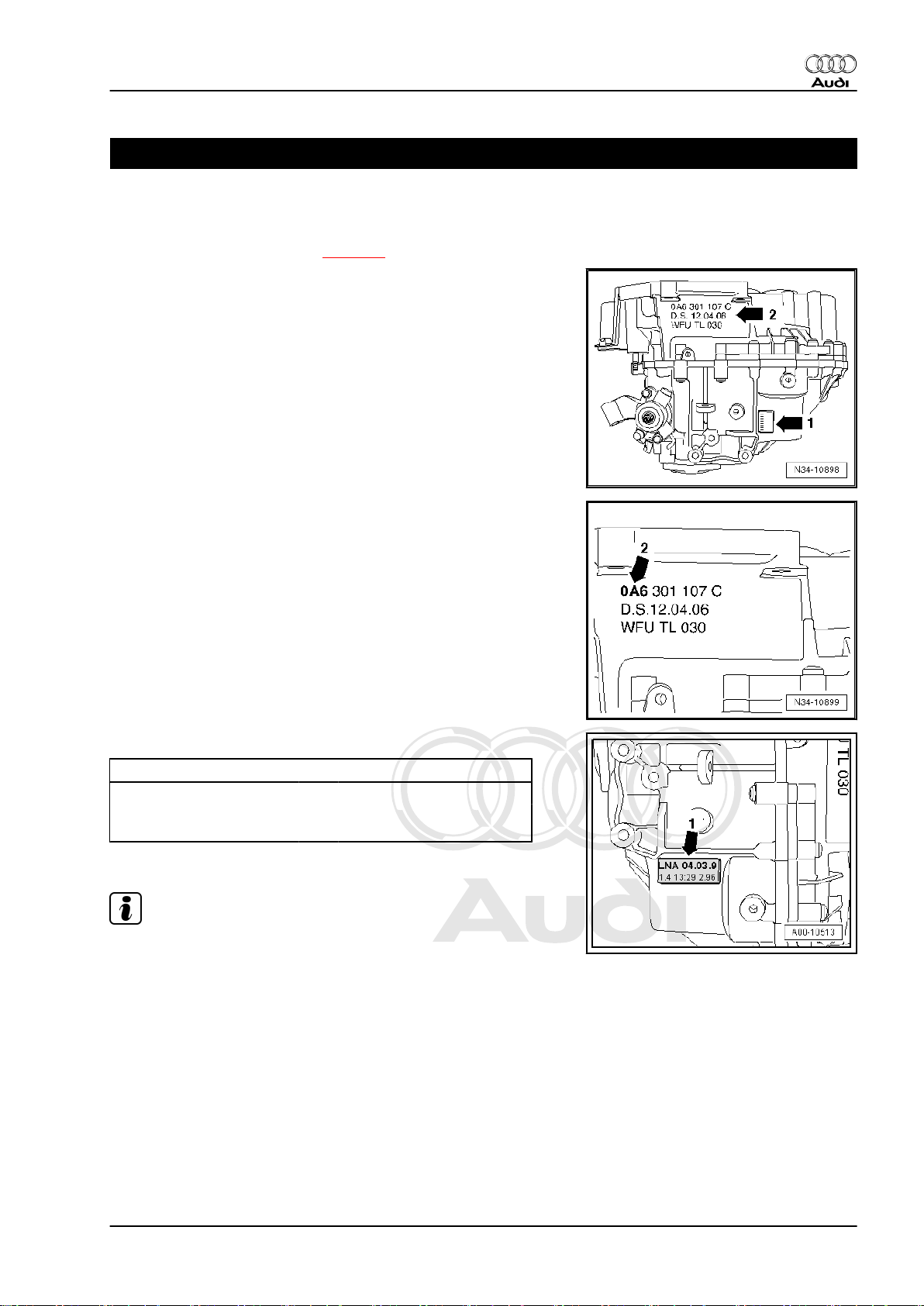
Location on gearbox
♦ Code letters and date of manufacture -arrow 1-
♦ Manual gearbox 0A6, four-wheel drive -arrow 2-
Manual gearbox 0A6, four-wheel drive -arrow 2-
Audi TT 2007 ➤
Code letters and date of manufacture of gearbox -arrow 1-
Example: LNA 04 03 9
Additional data identify the factory where the unit was built.
Note
I I I I
Code letters Day Month Year of manufac‐
ture (2007)
The code letters for the gearbox are also given on the vehicle data
stickers.
1. Gearbox identification 1
Page 6
Protected by copyright. Copying for private or commercial purposes, in part or in whole, is not
permitted unless authorised by AUDI AG. AUDI AG does not guarantee or accept any liability
with respect to the correctness of information in this document. Copyright by AUDI AG.
Audi TT 2007 ➤
6-speed manual gearbox 0A6, four-wheel drive - Edition 06.2009
2 Code letters, allocation, transmission ratios, capacities
Manual gearbox 0A6 four-wheel drive
Code letters
Manufactured from 07.08 03.09
Allocation Model Audi TT 2007 ▸ Audi TT 2007 ▸
Ratio Final drive I
for 1st/2nd gear
i = Z2 : Z
1
for 3rd – 6th gear
for reverse gear
Capacity of manual gearbox 2.3 litres
Capacity of bevel box 0.9 litres
Clutch actuation Hydraulic
The following data can be found in the ⇒ Electronic parts catalogue .
♦ Individual gear ratios
♦ Gear oil specification
♦ Allocation of bevel box
♦ Allocation of drive shaft flange type
♦ Allocation of clutch type
♦ Rear final drive identification
to
LNA MCK
Engine 2.5 ltr. TFSI - 250 kW 2.5 ltr. TFSI - 250 kW
64 : 17 = 3.765 64 : 17 = 3.765
Final drive II
Final drive III
64 : 22 = 2.909 64 : 22 = 2.909
64 : 20 = 3.200 64 : 20 = 3.200
2 Rep. Gr.00 - Technical data
Page 7
Protected by copyright. Copying for private or commercial purposes, in part or in whole, is not
permitted unless authorised by AUDI AG. AUDI AG does not guarantee or accept any liability
with respect to the correctness of information in this document. Copyright by AUDI AG.
6-speed manual gearbox 0A6, four-wheel drive - Edition 06.2009
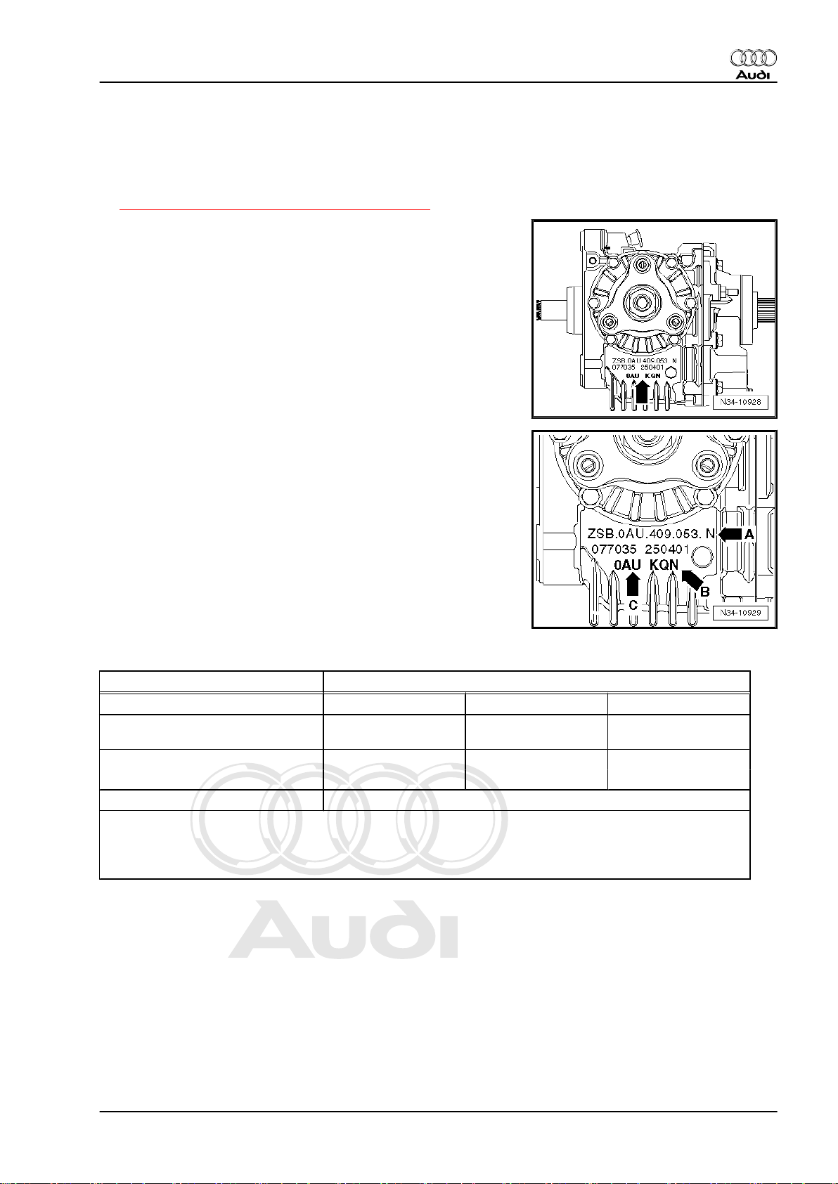
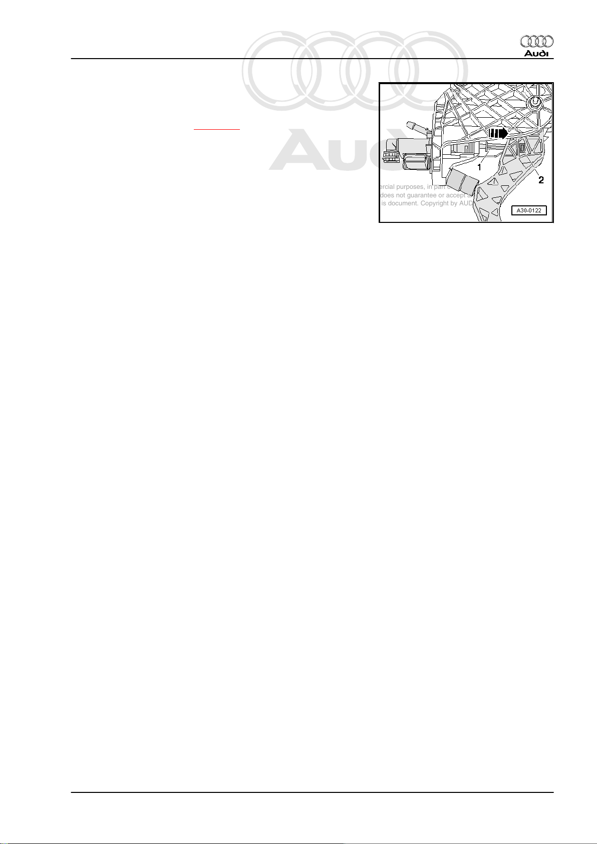
3 Bevel box identification
The bevel box 0AU or 0A6 is used in conjunction with the 6-speed
manual gearbox 0A6 (four-wheel drive).
♦ ⇒ “3.1 Code letters, allocation, capacities”, page 3
Location on bevel box
Code letters and part number of bevel box -arrow-
-Arrow A- part number of bevel box
-Arrow B- code letters of bevel box
-Arrow C- bevel box 0AU or 0A6
♦ If the code letters are not shown, the unit can be identified via
the Part No. ⇒ Electronic parts catalogue .
Additional data are manufacture-related.
Audi TT 2007 ➤
3.1 Code letters, allocation, capacities
Bevel box 0AU/0A6
Code letters LGS LGY LGZ
Manufactured from
to
Allocation Model Audi TT 2007 ▸ Audi TT 2007 ▸ Audi TT 2007 ▸
Engine 2.5 ltr. TFSI - 250 kW 2.5 ltr. TFSI - 250 kW 2.5 ltr. TFSI - 250 kW
Capacity 0.9 litres
The following data can be found in the ⇒ Electronic parts catalogue .
♦ Bevel box gear oil specification
♦ Allocation of manual gearbox
07.08 07.08 07.08
3. Bevel box identification 3
Page 8
Protected by copyright. Copying for private or commercial purposes, in part or in whole, is not
permitted unless authorised by AUDI AG. AUDI AG does not guarantee or accept any liability
with respect to the correctness of information in this document. Copyright by AUDI AG.
Audi TT 2007 ➤
6-speed manual gearbox 0A6, four-wheel drive - Edition 06.2009
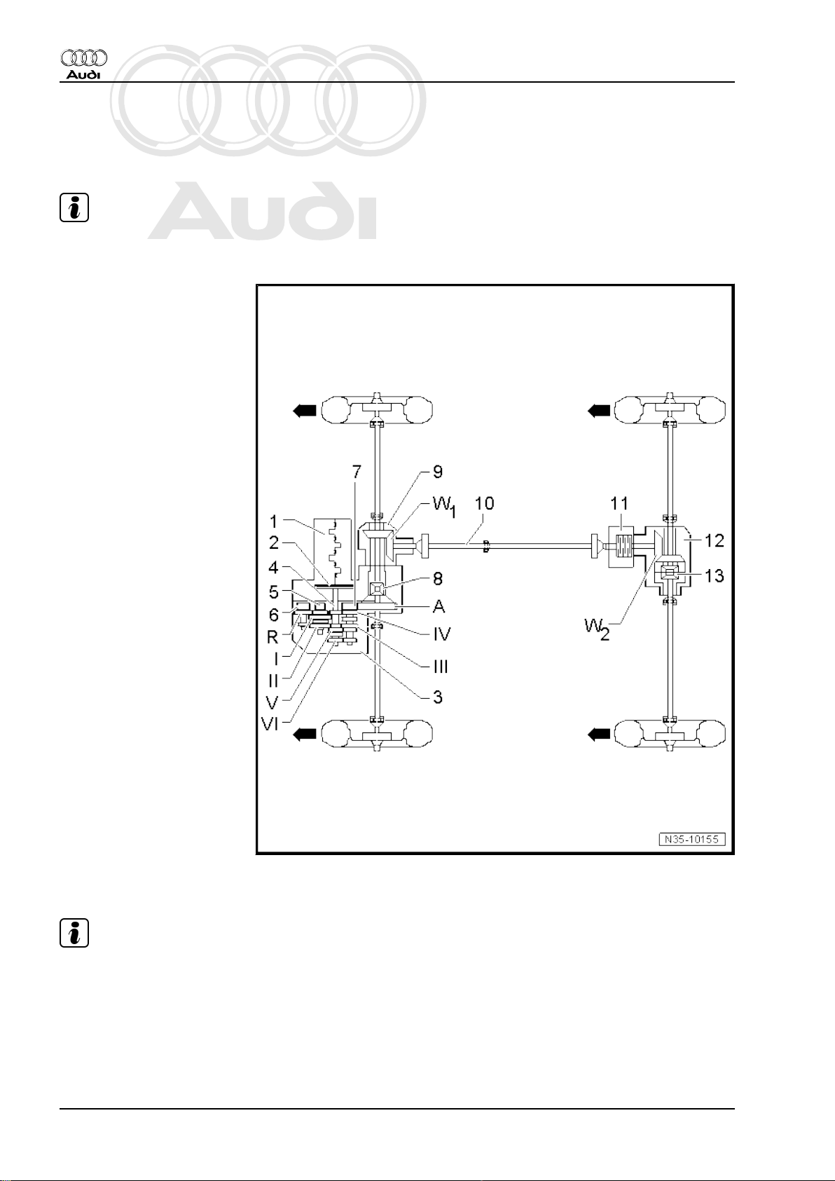
4 Transmission layout
Identification
Note
-Arrows- point in direction of travel.
1 - Engine
2 - Clutch
3 - Manual gearbox
4 - Input shaft
5 - Output shaft for 1st/2nd
gear
6 - Output shaft for reverse
gear
7 - Output shaft for 3rd – 6th
gear
8 - Differential
9 - Bevel box
10 - Propshaft
11 - Haldex coupling
12 - Rear final drive
13 - Differential
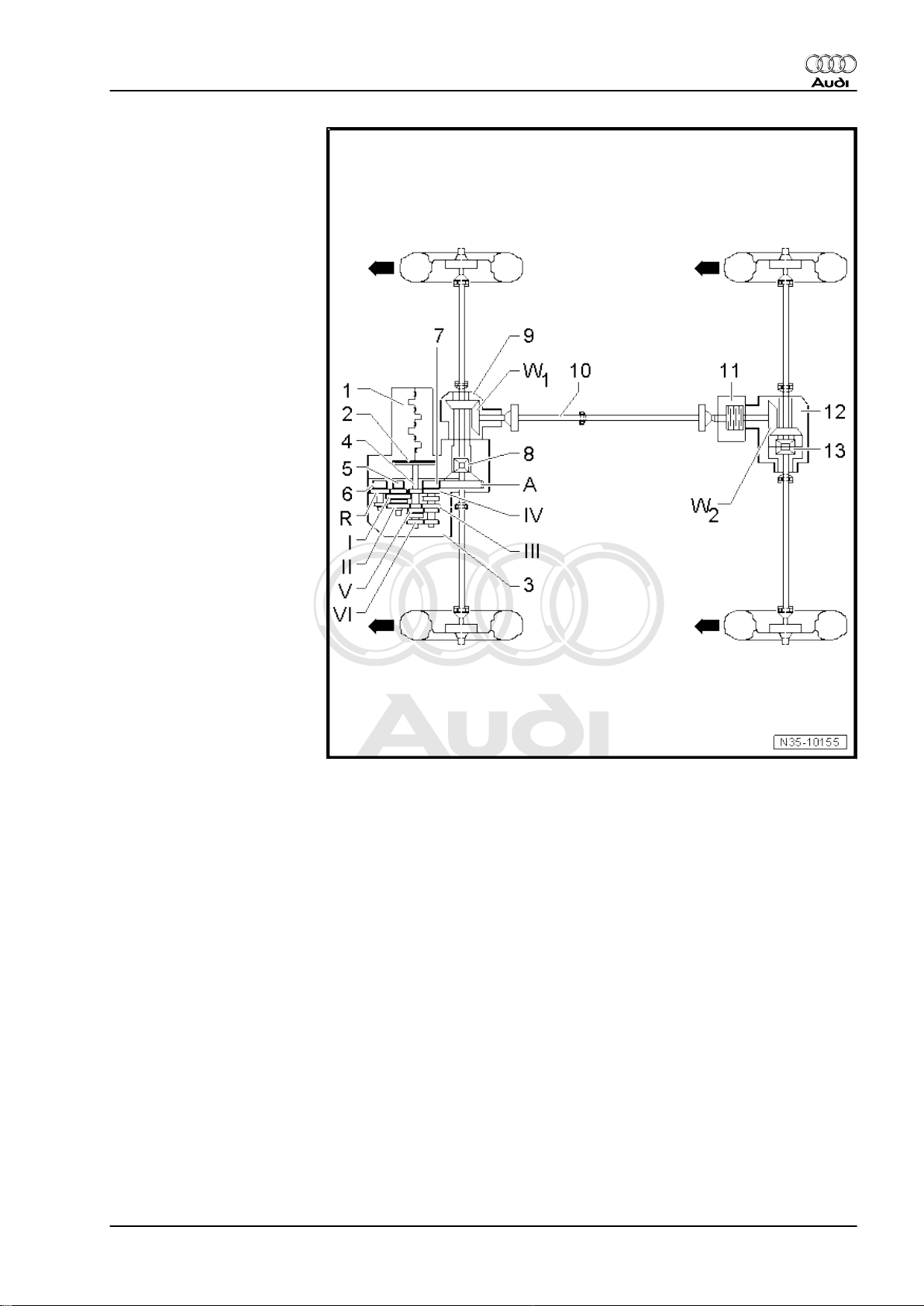
Ratio
Note
-Arrows- point in direction of travel.
4 Rep. Gr.00 - Technical data
Page 9
Protected by copyright. Copying for private or commercial purposes, in part or in whole, is not
permitted unless authorised by AUDI AG. AUDI AG does not guarantee or accept any liability
with respect to the correctness of information in this document. Copyright by AUDI AG.
I - 1st gear
II - 2nd gear
III - 3rd gear
IV - 4th gear
V - 5th gear
VI - 6th gear
R - Reverse gear
A - Final drive
W1 - Front bevel gears
W2 - Rear bevel gears
Audi TT 2007 ➤
6-speed manual gearbox 0A6, four-wheel drive - Edition 06.2009
4. Transmission layout 5
Page 10
Protected by copyright. Copying for private or commercial purposes, in part or in whole, is not
permitted unless authorised by AUDI AG. AUDI AG does not guarantee or accept any liability
with respect to the correctness of information in this document. Copyright by AUDI AG.
Audi TT 2007 ➤
6-speed manual gearbox 0A6, four-wheel drive - Edition 06.2009
5 General repair instructions
Proper tools and the maximum possible care and cleanliness are
essential for satisfactory gearbox repairs. The usual basic safety
precautions also naturally apply when carrying out repair work.
A number of generally applicable instructions for the various re‐
pair procedures - which were previously repeated at numerous
places in the Workshop Manual - are summarised here. They ap‐
ply to the work described in this Manual.
5.1 Contact corrosion!
♦ The gearbox housing components can be made of a magne‐
sium or aluminium alloy.
♦ Bolts and other components which are in direct contact with
the gearbox have a surface treatment which is compatible with
the housing material.
♦ If the incorrect parts are used (bolts, nuts, washers etc.), this
will cause contact corrosion and damage the gearbox housing
components.
♦ If you are not sure whether used parts can be re-installed, al‐
ways fit new parts ⇒ Electronic parts catalogue .
Caution
Damage caused by contact corrosion is not covered under
warranty.
5.2 Repair instructions
Special tools
♦ For a complete list of special tools used in this Workshop
Manual ⇒ Workshop equipment and special tools .
Gearbox
♦ Thoroughly clean all joints and connections and the surround‐
ing areas before dismantling.
♦ When installing manual gearbox, ensure that the dowel
sleeves between the engine and the gearbox are correctly lo‐
cated.
♦ For allocation of bolts and other components, refer to ⇒ Elec‐
tronic parts catalogue .
♦ Clean contact surfaces when assembling mounting brackets
and waxed components. The contact surfaces must be free of
wax and grease.
♦ After installing a replacement gearbox, check oil level and top
up with gear oil as required
⇒ “11 Checking oil level in manual gearbox”, page 85 or
⇒ “12.1 Checking gear oil level in bevel box”, page 86 .
♦ Capacities and specifications ⇒ page 2
6 Rep. Gr.00 - Technical data
Page 11
Protected by copyright. Copying for private or commercial purposes, in part or in whole, is not
permitted unless authorised by AUDI AG. AUDI AG does not guarantee or accept any liability
with respect to the correctness of information in this document. Copyright by AUDI AG.
6-speed manual gearbox 0A6, four-wheel drive - Edition 06.2009
Oil seals, seals, O-rings and gaskets
♦ Renew O-rings, seals and gaskets.
♦ After removing gaskets and seals, always inspect the contact
surface on the housing or shaft for burrs resulting from removal
or for other signs of damage.
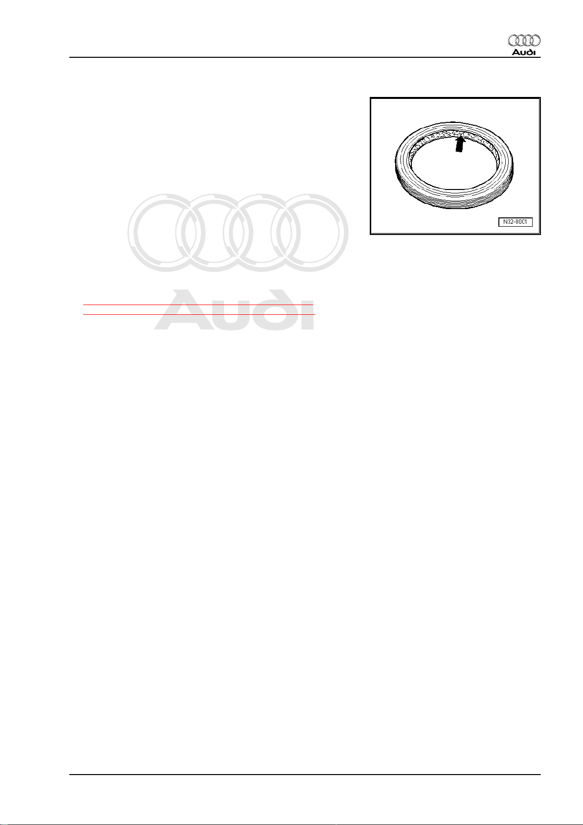
♦ Before installing oil seals, lightly oil the outer circumference of
the seal and fill the space between the sealing lips -arrowabout half full with grease -G 052 128 A1- .
♦ The open side of the oil seal should face the side containing
the fluid.
♦ When installing a new oil seal, position the seal such that the
sealing lip does not contact the shaft in the same place as the
old seal (make use of installation depth tolerances).
♦ Lightly lubricate O-rings with oil before installation to prevent
them being trapped during assembly.
♦ Check oil level after installing new gaskets, O-rings and oil
seals
⇒ “11 Checking oil level in manual gearbox”, page 85 or
⇒ “12.1 Checking gear oil level in bevel box”, page 86 .
Sealants
♦ Thoroughly clean joint surfaces on gearbox housing etc. be‐
fore applying sealing paste.
♦ Apply sealing paste -AMV 188 200 03- evenly and not too
thick.
♦ Breather holes must remain free of sealing paste.
Audi TT 2007 ➤
5. General repair instructions 7
Page 12
Protected by copyright. Copying for private or commercial purposes, in part or in whole, is not
permitted unless authorised by AUDI AG. AUDI AG does not guarantee or accept any liability
with respect to the correctness of information in this document. Copyright by AUDI AG.
Audi TT 2007 ➤
6-speed manual gearbox 0A6, four-wheel drive - Edition 06.2009
Locking elements
♦ Do not over-stretch circlips.
♦ Renew circlips which have been damaged or over-tensioned.
♦ Circlips must be properly seated in the base of the groove.
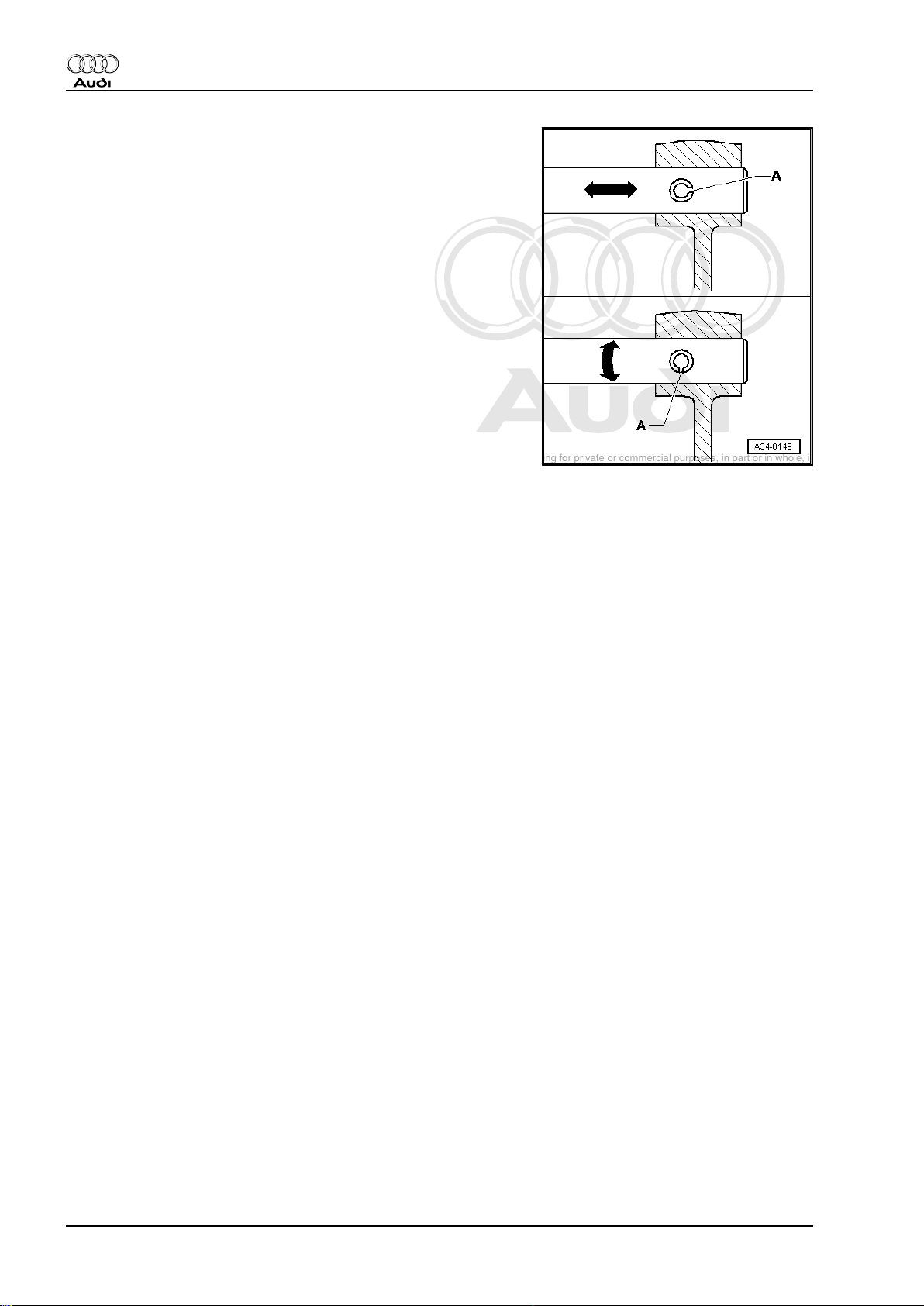
♦ Renew spring pins. Position: the slit -A- should be in line with
the line of force -arrow-.
Nuts, bolts
♦ Loosen the nuts and bolts in reverse sequence to the specified
tightening sequence.
♦ Nuts and bolts which secure covers and housings should be
loosened and tightened in diagonal sequence and in stages if
no tightening sequence is specified.
♦ Renew self-locking nuts and bolts.
♦ The tightening torques stated apply to non-oiled nuts and
bolts.
♦ Threaded holes which take self-locking bolts or bolts coated
with locking fluid must be cleaned (using a tap or similar). Oth‐
erwise there is a danger of the bolts shearing off the next time
they are removed.
♦ For all threaded connections, ensure that (where applicable)
the contact surfaces and the nuts and bolts are not coated with
wax until after assembly is completed.
Bearings
♦ Install new tapered roller bearings as supplied; do not lubricate
additionally with oil.
♦ Lubricate all bearings (except tapered roller bearings) with
gear oil before installing in gearbox.
♦ Heat inner races of tapered roller bearings to approx. 100°C
before installing. Press in onto stop when installing so there is
no axial clearance.
♦ Do not interchange inner or outer races of bearings of the
same size.
♦ If required, renew the tapered roller bearings on one shaft to‐
gether and use new bearings from a single manufacturer.
♦ Install needle bearings so the lettering (side with thicker metal)
faces towards the installing tool.
Shims
♦ Use a micrometer to measure the shims at several points.
Tolerance variations make it possible to obtain the exact shim
thickness required.
♦ Check for burrs and damage. Install only shims which are in
perfect condition.
Synchro-rings
8 Rep. Gr.00 - Technical data
Page 13
Protected by copyright. Copying for private or commercial purposes, in part or in whole, is not
permitted unless authorised by AUDI AG. AUDI AG does not guarantee or accept any liability
with respect to the correctness of information in this document. Copyright by AUDI AG.
6-speed manual gearbox 0A6, four-wheel drive - Edition 06.2009
♦ Do not interchange synchro-rings. When reusing always fit to
the same selector gear.
♦ Check for wear; renew if necessary.
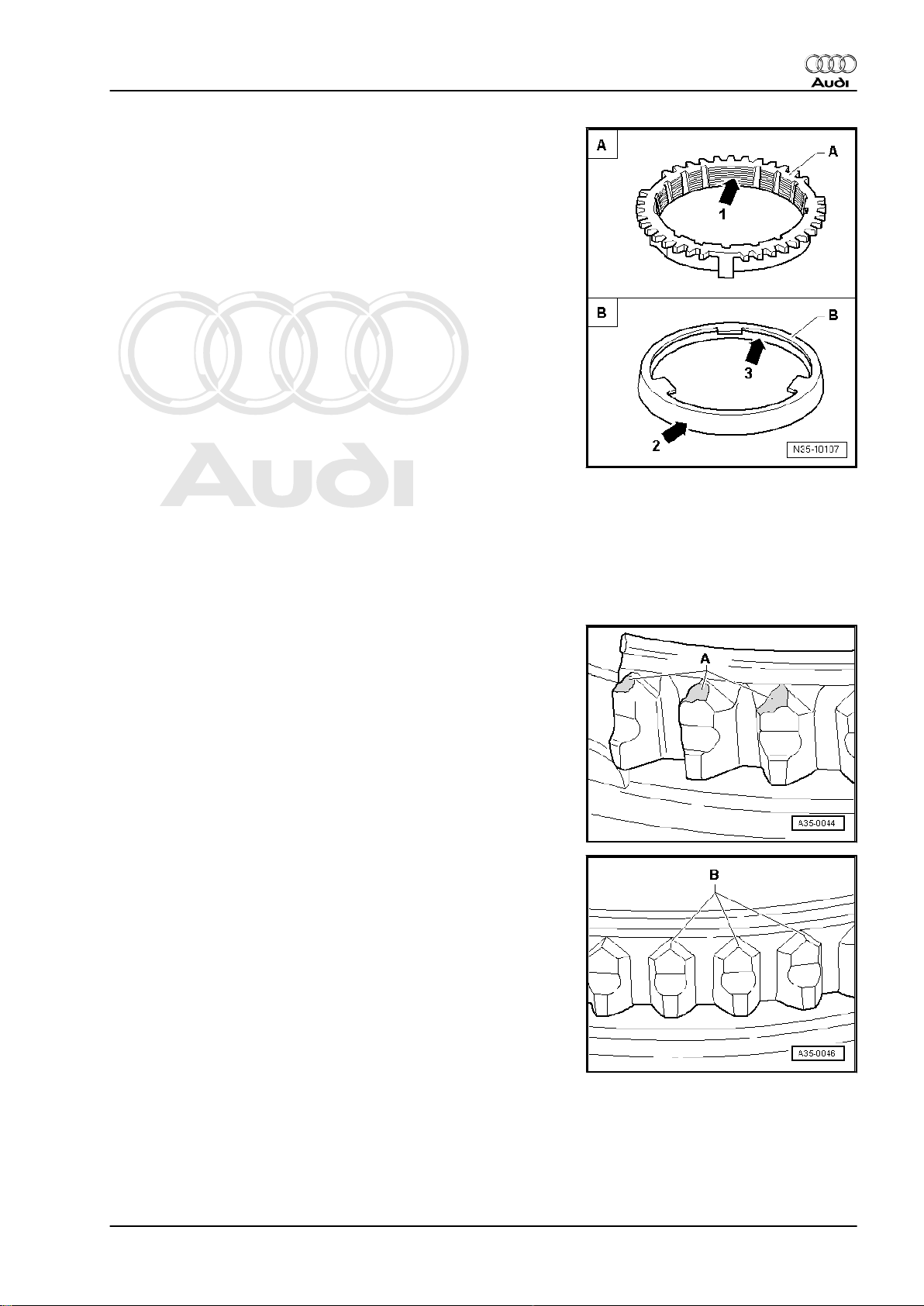
♦ Check the grooves -arrow 1- on synchro-ring -A- and on inner
ring for wear (flattened sections in grooves).
♦ Make sure that the coating of coated synchro-rings is not dam‐
aged.
♦ If an intermediate ring -B- is fitted, check the outer contact
surface -arrow 2- and inner contact surface -arrow 3- of the
intermediate ring for “scoring”, “visible traces of wear” and
“blue discolouration (caused by overheating)”.
♦ Check chamfer on selector gear for scoring and visible traces
of wear.
♦ Lubricate with gear oil before installing.
Gear wheels
♦ Before installing, clean and heat on a hotplate to approx. 100°
C.
♦ Use inductive heater -VAS 6414- to heat to approx. 100°C be‐
fore installing. Press home onto stop when installing so there
is no axial clearance.
Selector gears
♦ After installing, check 1st to 6th speed selector gears for min‐
imal axial play and freedom of movement.
Audi TT 2007 ➤
♦ Abnormal wear on synchro-ring or selector gear:
A - Worn ends of dog teeth on synchro-ring or selector gear.
♦ In comparison: intact synchro-ring or selector gear:
B - Intact ends of dog teeth on synchro-ring or selector gear.
5. General repair instructions 9
Page 14
Protected by copyright. Copying for private or commercial purposes, in part or in whole, is not
permitted unless authorised by AUDI AG. AUDI AG does not guarantee or accept any liability
with respect to the correctness of information in this document. Copyright by AUDI AG.
Audi TT 2007 ➤
6-speed manual gearbox 0A6, four-wheel drive - Edition 06.2009
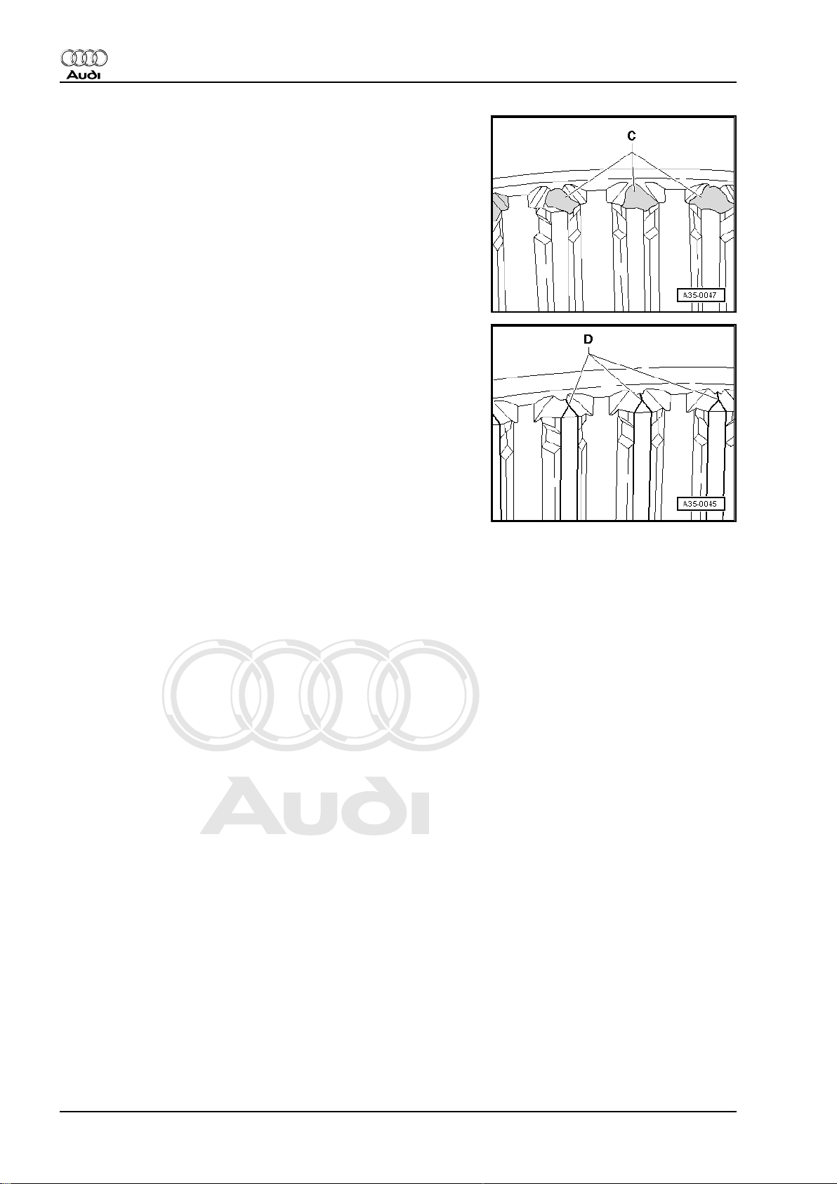
♦ Abnormal wear on locking collar:
C - Worn ends of internal splines on locking collar.
♦ In comparison: intact locking collar:
D - Intact ends of internal splines on locking collar.
Clutch actuation
♦ Ensure that the pressure plate is kept straight: loosen and
tighten bolts consecutively in steps of 90°.
♦ If the clutch has burnt out, thoroughly clean the clutch housing,
flywheel and parts of the engine facing the gearbox in order to
prevent odour.
♦ Only blow out dual-mass flywheel with compressed air.
♦ Pressure plates have an anti-corrosion coating and are
greased. With the exception of the friction surface for the
clutch plate, the pressure plate may not be cleaned. Otherwise
the service life of the clutch will be considerably reduced.
♦ The friction surface of the pressure plate and the dual-mass
flywheel must be cleaned (degreased) thoroughly.
♦ If the clutch pedal does not return to its initial position after it
is released (clutch pedal in rest position), you must bleed the
clutch system.
10 Rep. Gr.00 - Technical data
Page 15
Protected by copyright. Copying for private or commercial purposes, in part or in whole, is not
permitted unless authorised by AUDI AG. AUDI AG does not guarantee or accept any liability
with respect to the correctness of information in this document. Copyright by AUDI AG.
6-speed manual gearbox 0A6, four-wheel drive - Edition 06.2009
30 – Clutch
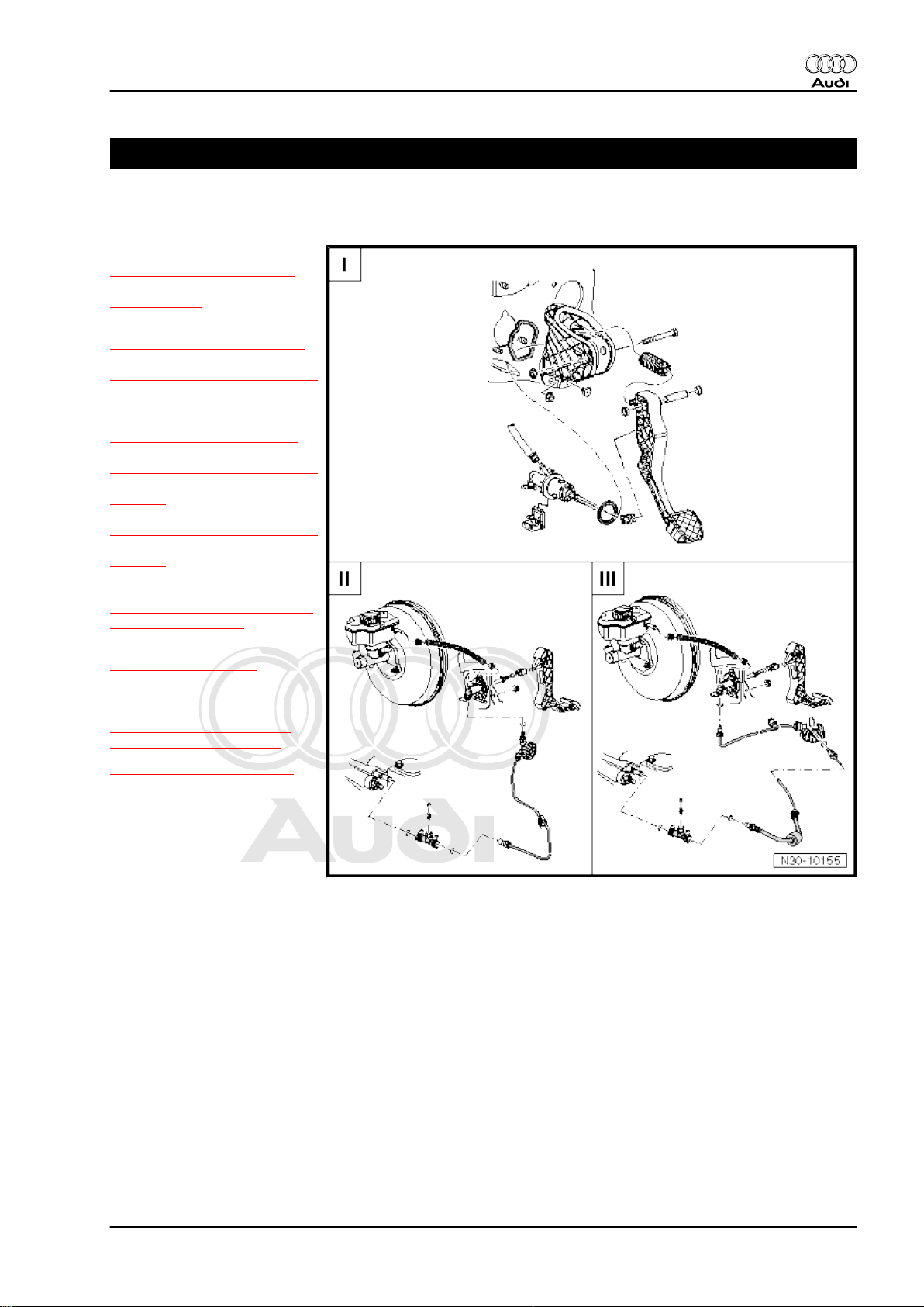
1 Overview - clutch mechanism
I -
⇒ “2 Exploded view - pedal
cluster, clutch master cylin‐
der”, page 12
⇒ “2.1 Removing and installing
over-centre spring”, page 13
⇒ “2.2 Removing and installing
clutch pedal”, page 15
⇒ “2.3 Removing and installing
mounting bracket”, page 18
⇒ “2.4 Removing and installing
clutch position sender G476 ”,
page 20
Audi TT 2007 ➤
⇒ “2.5 Removing and installing
clutch master cylinder”,
page 21
II -
⇒ “3 Exploded view - hydraul‐
ics (LHD)”, page 24
⇒ “3.1 Removing and installing
pipe/hose assembly”,
page 25
III -
⇒ “3.2 Exploded view - hy‐
draulics (RHD)”, page 27
⇒ “3.3 Bleeding clutch sys‐
tem”, page 28
1. Overview - clutch mechanism 11
Page 16
Protected by copyright. Copying for private or commercial purposes, in part or in whole, is not
permitted unless authorised by AUDI AG. AUDI AG does not guarantee or accept any liability
with respect to the correctness of information in this document. Copyright by AUDI AG.
Audi TT 2007 ➤
6-speed manual gearbox 0A6, four-wheel drive - Edition 06.2009
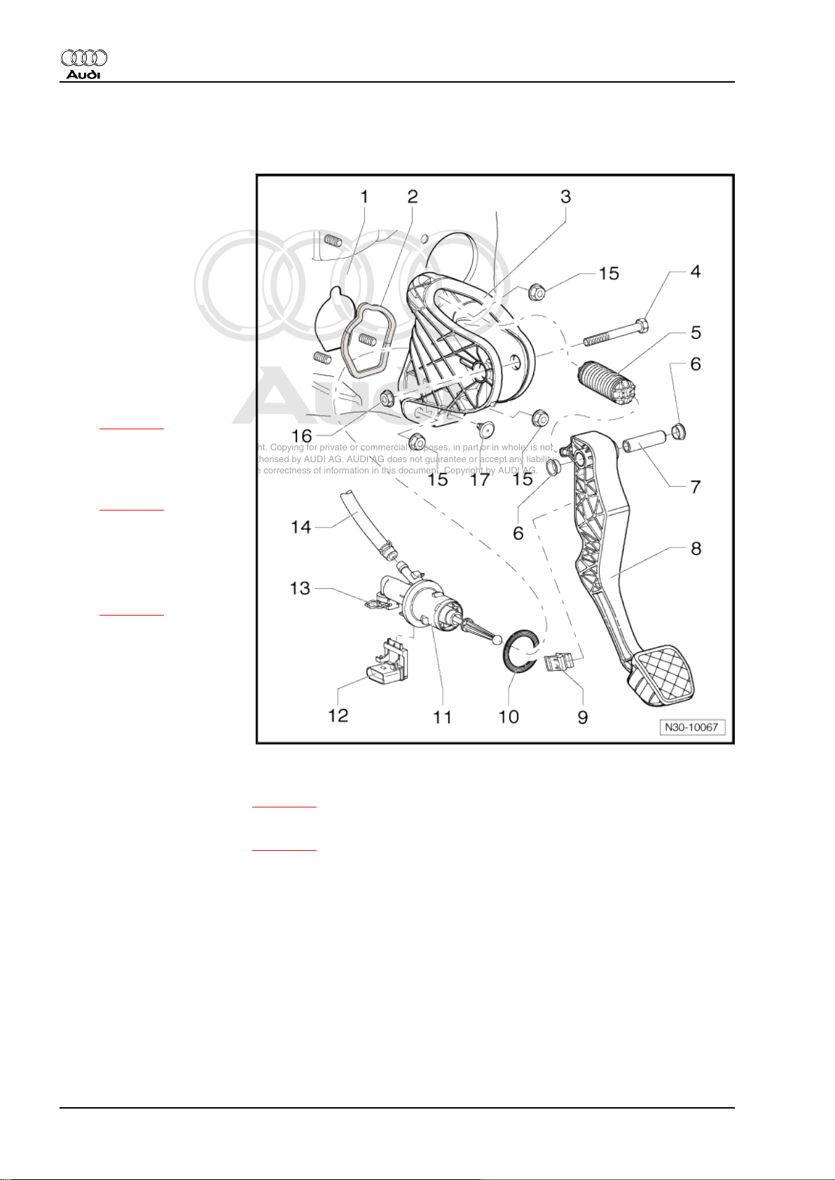
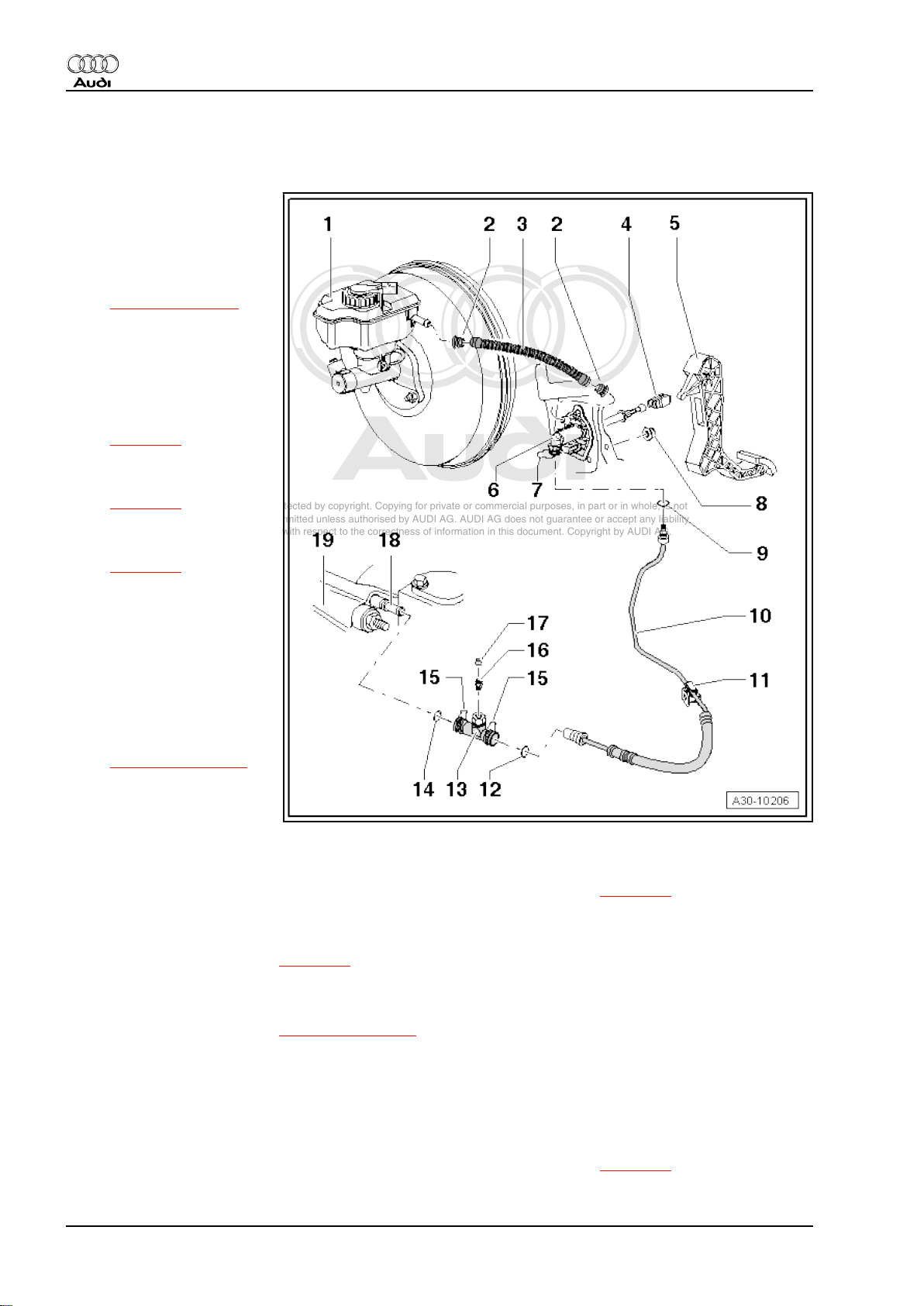
2 Exploded view - pedal cluster, clutch master cylinder
1 - Bulkhead
❑ With mounting for
mounting bracket
2 - Gasket
❑ Renew
❑ Between mounting
bracket and bulkhead
❑ Self-adhesive
❑ Bond onto mounting
bracket
3 - Mounting bracket
❑ For clutch pedal
❑ Removing and installing
⇒ page 18
4 - Bolt
5 - Over-centre spring
❑ Removing and installing
⇒ page 13
6 - Bearing bush
7 - Pivot pin
8 - Clutch pedal
❑ Removing and installing
⇒ page 15
9 - Retaining clip
❑ For operating rod for
clutch master cylinder
10 - Seal
❑ Renew
❑ Between clutch master
cylinder and mounting
bracket
11 - Clutch master cylinder
❑ Removing and installing ⇒ page 21
12 - Clutch position sender -G476-
❑ Removing and installing ⇒ page 20
❑ Can be checked in “Guided Fault Finding”, using vehicle diagnostic, testing and information system -
VAS 5051-
13 - Retaining clip
❑ To remove and install pipe/hose assembly, pull out clip as far as it will go
14 - Supply hose
❑ To brake fluid reservoir
15 - Nut
❑ For securing mounting bracket to bulkhead
❑ 20 Nm
❑ 3x
❑ Self-locking
❑ Renew
12 Rep. Gr.30 - Clutch
Page 17
Protected by copyright. Copying for private or commercial purposes, in part or in whole, is not
permitted unless authorised by AUDI AG. AUDI AG does not guarantee or accept any liability
with respect to the correctness of information in this document. Copyright by AUDI AG.
6-speed manual gearbox 0A6, four-wheel drive - Edition 06.2009
16 - Nut
❑ 25 Nm
❑ Self-locking
❑ Renew
17 - Stop
❑ For clutch pedal
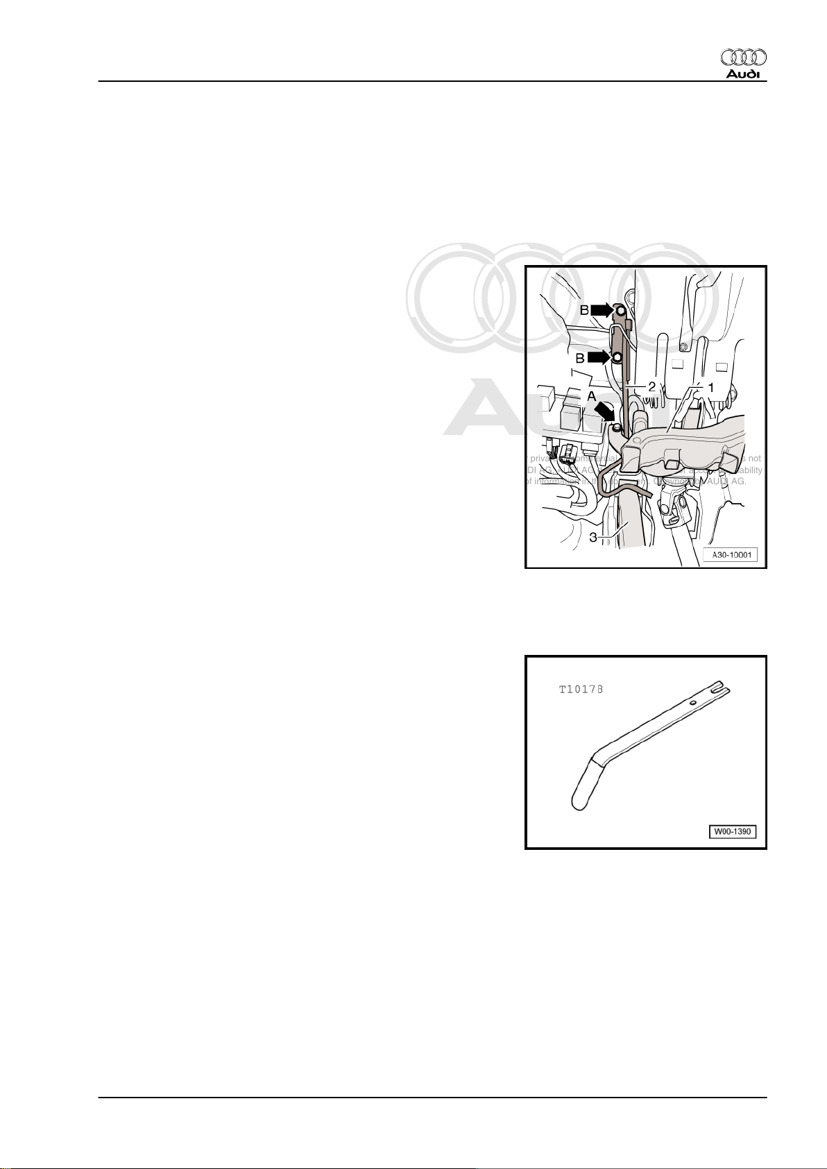
Crash bar - tightening torque
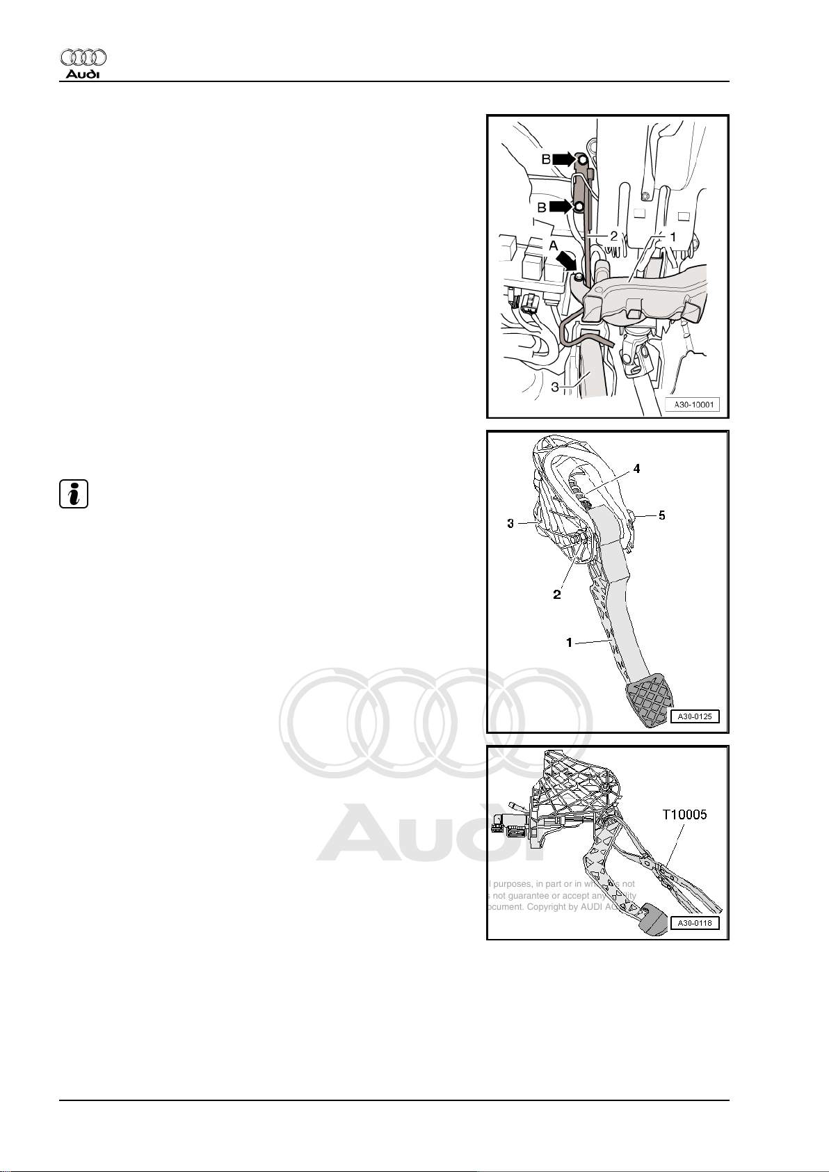
– Fit crash bar -2- and tighten 1 or 2 bolts (depending on version)
-arrows B-.
• M6 10 Nm
• M8 20 Nm
Audi TT 2007 ➤
2.1 Removing and installing over-centre spring
Special tools and workshop equipment required
♦ Assembly tool -T10178-
♦ Grease -G 000 450 02-
2. Exploded view - pedal cluster, clutch master cylinder 13
Page 18
Protected by copyright. Copying for private or commercial purposes, in part or in whole, is not
permitted unless authorised by AUDI AG. AUDI AG does not guarantee or accept any liability
with respect to the correctness of information in this document. Copyright by AUDI AG.
Audi TT 2007 ➤
6-speed manual gearbox 0A6, four-wheel drive - Edition 06.2009
Removing
• Clutch pedal mounting bracket fitted in vehicle
– Move driver's seat away from pedals.
– Remove storage compartment on driver's side ⇒ Rep. Gr.
68 .
– Unscrew bolt -arrow A- and remove footwell air outlet (front
left) -1-.
– Unclip wiring harness at rear of footwell air outlet -1- and move
clear to one side.
– Unbolt crash bar -2- (secured by one or two bolts -arrows B-,
depending on version).
– Unbolt clutch pedal -1- from mounting bracket -3-. To do this,
remove nut -2- and pull out bolt -5-.
Note
The clutch pedal does not have to be detached from the operating
rod on the clutch master cylinder.
– Pivot clutch pedal down slightly and and take over-centre
spring -4- out of mounting bracket.
Installing
• Tightening torque ⇒ page 12
Installation is carried out in reverse sequence; note the following:
Note
♦
Renew self-locking nut.
♦
Lubricate all bearings and contact surfaces with grease -G 000
450 02- .
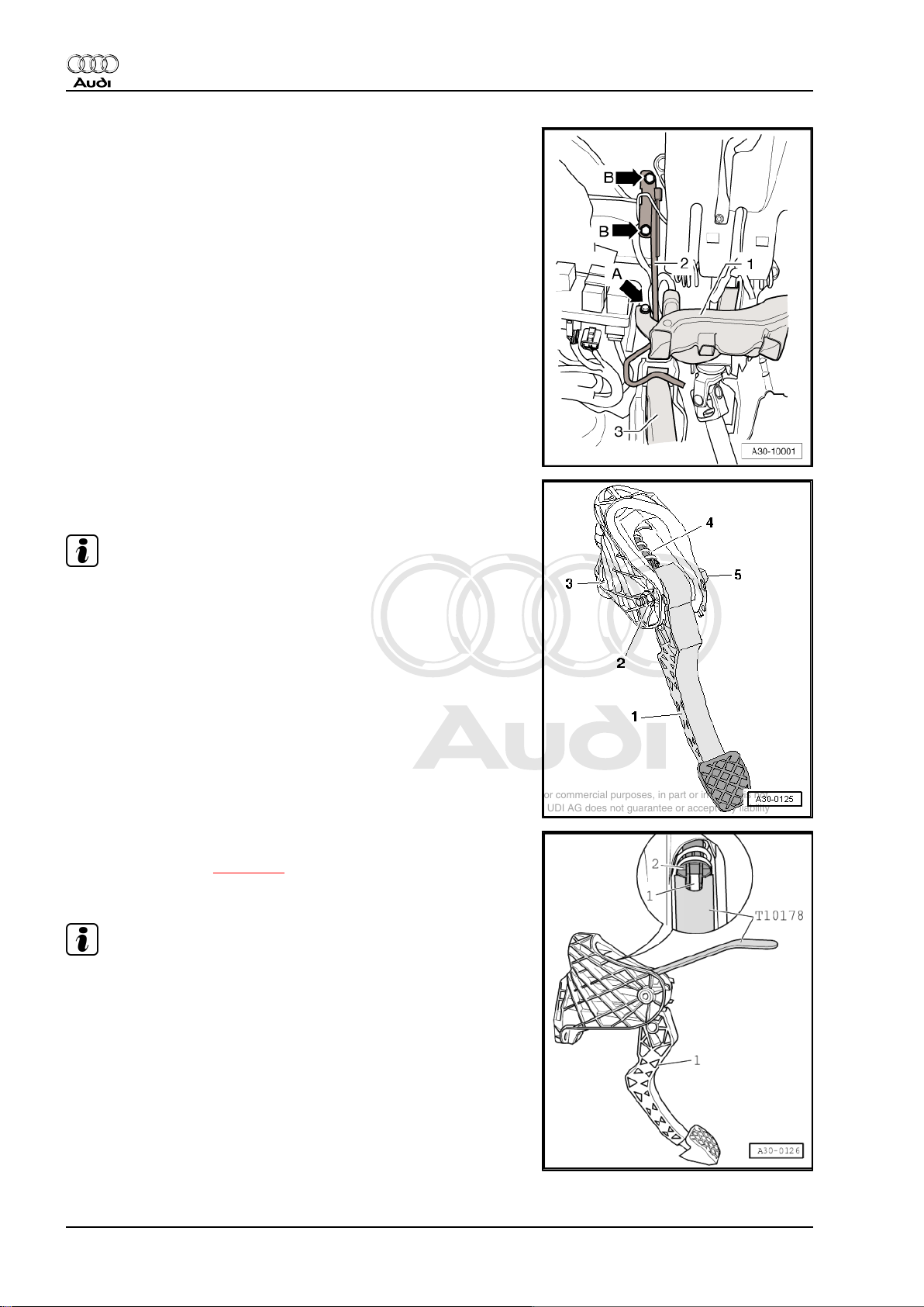
– Fit over-centre spring -2- into mounting bracket from above
while holding end of spring in correct position with assembly
tool -T10178- .
14 Rep. Gr.30 - Clutch
Page 19
Protected by copyright. Copying for private or commercial purposes, in part or in whole, is not
permitted unless authorised by AUDI AG. AUDI AG does not guarantee or accept any liability
with respect to the correctness of information in this document. Copyright by AUDI AG.
6-speed manual gearbox 0A6, four-wheel drive - Edition 06.2009
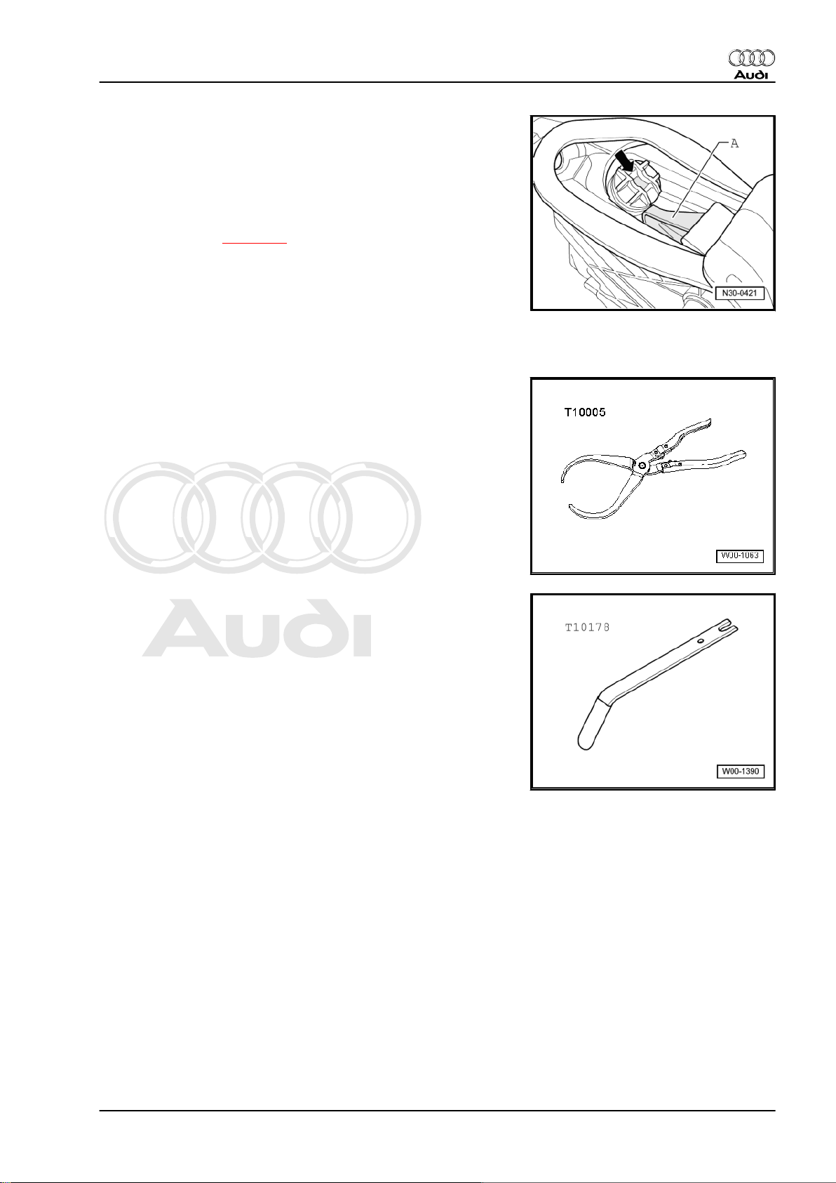
• Socket -arrow- of over-centre spring must be in vertical posi‐
tion.
– Fit actuator on clutch pedal -A- into corresponding socket in
over-centre spring -arrow-.
– Press clutch pedal slightly, push bolt through and tighten self-
locking nut.
– Install crash bar ⇒ page 13 .
– Install front footwell vent (left-side) ⇒ Rep. Gr. 80 .
– Install storage compartment on driver's side ⇒ Rep. Gr. 68 .
2.2 Removing and installing clutch pedal
Special tools and workshop equipment required
♦ Pliers -T10005-
Audi TT 2007 ➤
♦ Assembly tool -T10178-
♦ Grease -G 000 450 02-
2. Exploded view - pedal cluster, clutch master cylinder 15
Page 20
Protected by copyright. Copying for private or commercial purposes, in part or in whole, is not
permitted unless authorised by AUDI AG. AUDI AG does not guarantee or accept any liability
with respect to the correctness of information in this document. Copyright by AUDI AG.
Audi TT 2007 ➤
6-speed manual gearbox 0A6, four-wheel drive - Edition 06.2009
Removing
• Clutch pedal mounting bracket fitted in vehicle
– Move driver's seat away from pedals.
– Remove storage compartment on driver's side ⇒ Rep. Gr.
68 .
– Unscrew bolt -arrow A- and remove footwell air outlet (front
left) -1-.
– Unclip wiring harness at rear of footwell air outlet -1- and move
clear to one side.
– Unbolt crash bar -2- (secured by one or two bolts -arrows B-,
depending on version).
– Unbolt clutch pedal -1- from mounting bracket -3-. To do this,
remove nut -2- and pull out bolt -5-.
Note
-Item 4- can be disregarded.
– Release retaining clip for operating rod on clutch pedal using
pliers -T10005- .
– Remove clutch pedal.
16 Rep. Gr.30 - Clutch
Page 21
Protected by copyright. Copying for private or commercial purposes, in part or in whole, is not
permitted unless authorised by AUDI AG. AUDI AG does not guarantee or accept any liability
with respect to the correctness of information in this document. Copyright by AUDI AG.
6-speed manual gearbox 0A6, four-wheel drive - Edition 06.2009
Installing
• Tightening torque ⇒ page 12
Installation is carried out in reverse sequence; note the following:
Note
♦
Renew self-locking nut.
♦
Lubricate all bearings and contact surfaces with grease -G 000
450 02- .
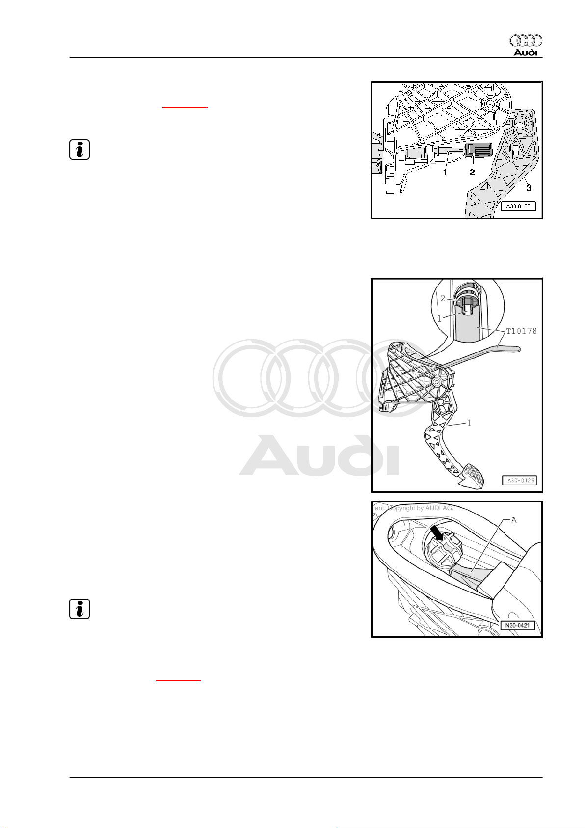
– Position retaining clip -2- on operating rod -1- for clutch master
cylinder.
– Press retaining clip into mounting on clutch pedal so that it
snaps into place.
– Fit over-centre spring -2- into mounting bracket from above
while holding end of spring in correct position with assembly
tool -T10178- .
Audi TT 2007 ➤
• Socket -arrow- of over-centre spring must be in vertical posi‐
tion.
– Fit actuator on clutch pedal -A- into corresponding socket in
over-centre spring -arrow-.
– Press top of clutch pedal forwards against spring pressure of
over-centre spring, push through bolt and tighten self-locking
nut.
Note
It is easier to press the clutch pedal against the spring if you pull
back the bottom of the pedal carefully as you bring the top of the
pedal into installation position.
– Install crash bar ⇒ page 13 .
– Install front footwell vent (left-side) ⇒ Rep. Gr. 80 .
– Install storage compartment on driver's side ⇒ Rep. Gr. 68 .
2. Exploded view - pedal cluster, clutch master cylinder 17
Page 22
Protected by copyright. Copying for private or commercial purposes, in part or in whole, is not
permitted unless authorised by AUDI AG. AUDI AG does not guarantee or accept any liability
with respect to the correctness of information in this document. Copyright by AUDI AG.
Audi TT 2007 ➤
6-speed manual gearbox 0A6, four-wheel drive - Edition 06.2009
2.3 Removing and installing mounting bracket
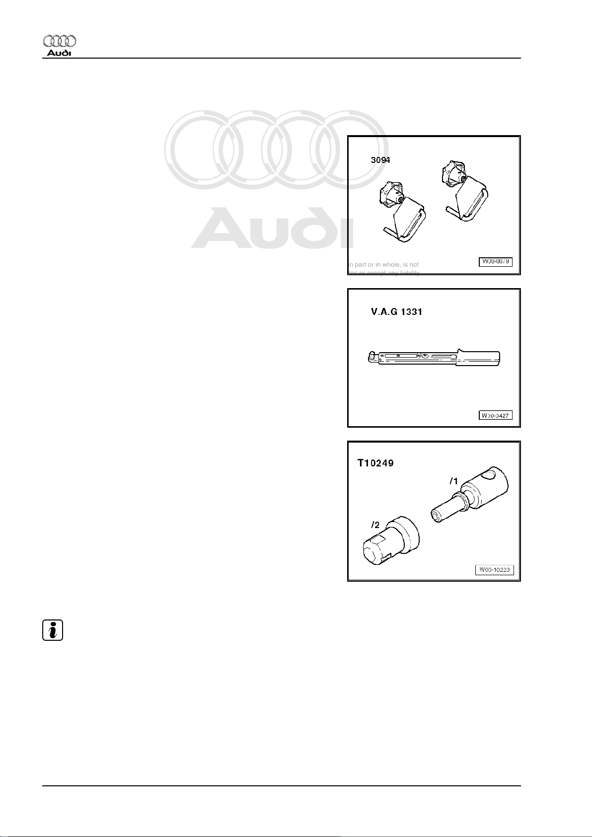
Special tools and workshop equipment required
♦ Hose clamps, up to Ø 25 mm -3094-
♦ Torque wrench -V.A.G 1331-
♦ Sealing tool -T10249-
Removing
Note
♦
In the following steps make sure that no brake fluid escapes
onto the longitudinal member or onto the gearbox below. If this
does happen, clean the affected area thoroughly.
♦
Place a lint-free cloth under the master cylinder.
18 Rep. Gr.30 - Clutch
Page 23
Protected by copyright. Copying for private or commercial purposes, in part or in whole, is not
permitted unless authorised by AUDI AG. AUDI AG does not guarantee or accept any liability
with respect to the correctness of information in this document. Copyright by AUDI AG.
6-speed manual gearbox 0A6, four-wheel drive - Edition 06.2009
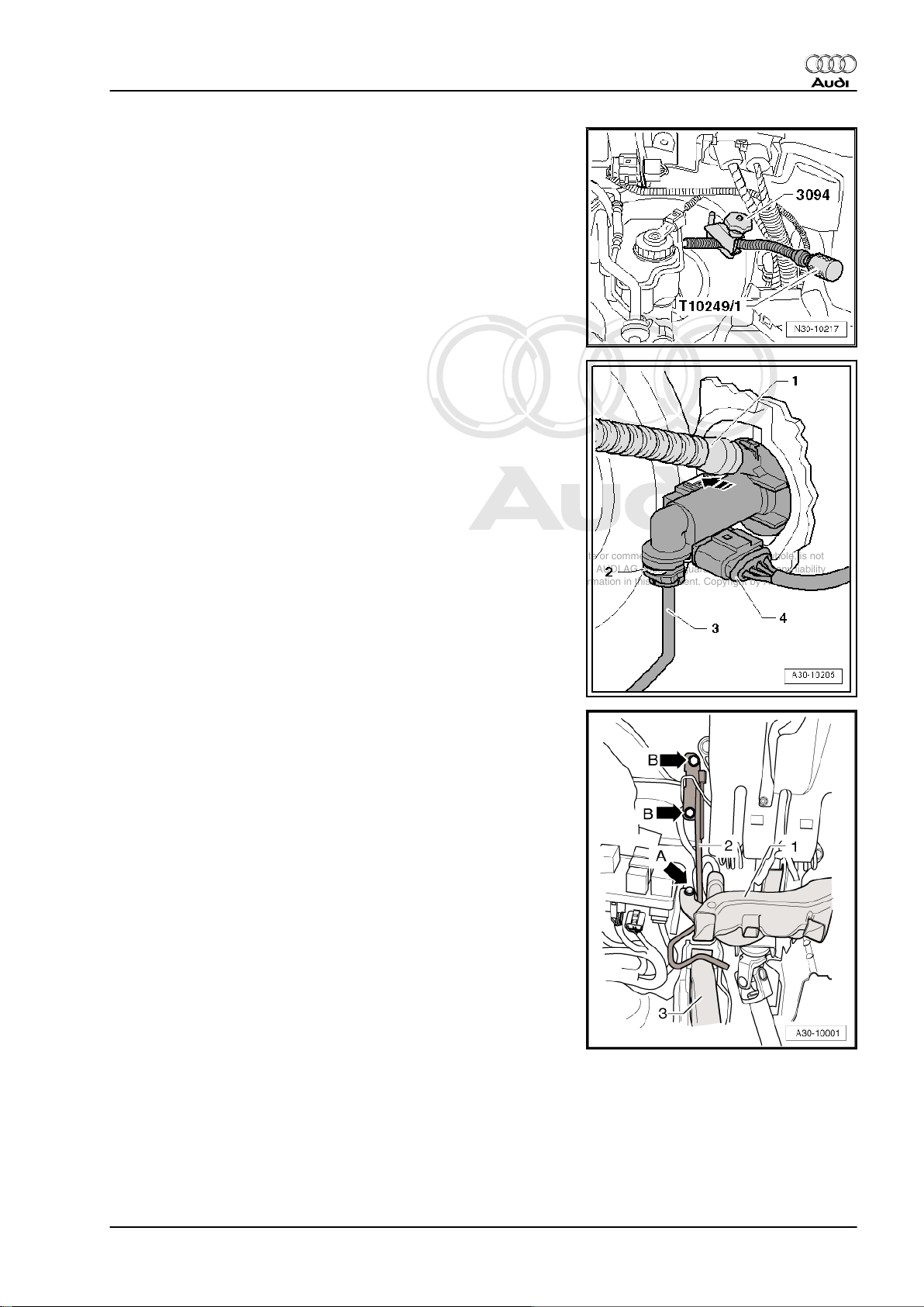
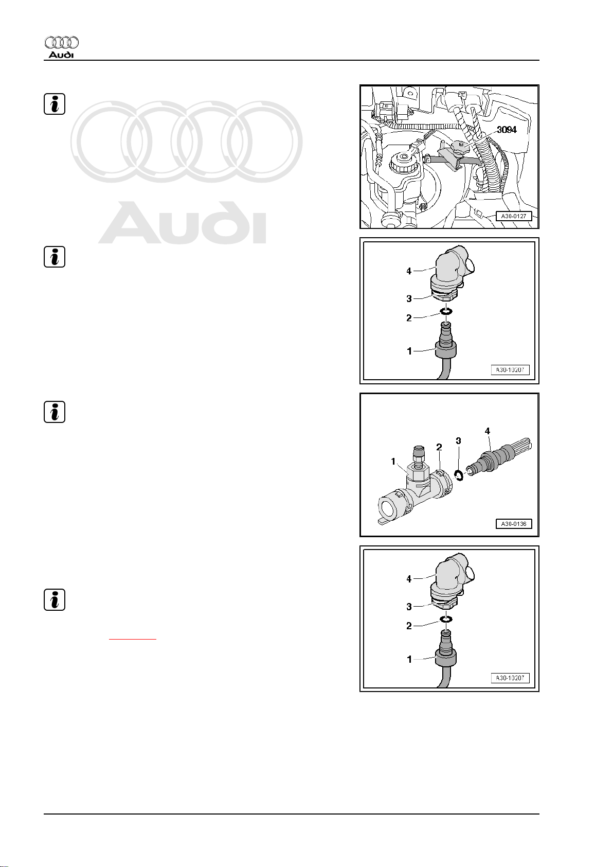
– Use hose clamp -3094- to clamp off supply hose to clutch
master cylinder.
– Pull supply hose -1- off master cylinder.
– Additionally seal off supply hose -1- using sealing tool -
T10249/1- (⇒ illustration above).
– Release securing clip -2- and disconnect pipe -3-.
– Unclip and detach clutch position sender -G476- from clutch
master cylinder -arrow-. Electrical connector -4- can remain
connected.
Audi TT 2007 ➤
– Move driver's seat to rear as far as possible and move steering
wheel into uppermost position.
– Remove storage compartment on driver's side ⇒ Rep. Gr.
68 .
– Unscrew bolt -arrow A- and remove footwell air outlet (front
left) -1-.
– Unclip wiring harness at rear of footwell air outlet -1- and move
clear to one side.
– Unbolt crash bar -2- (secured by one or two bolts -arrows B-,
depending on version).
2. Exploded view - pedal cluster, clutch master cylinder 19
Page 24
Protected by copyright. Copying for private or commercial purposes, in part or in whole, is not
permitted unless authorised by AUDI AG. AUDI AG does not guarantee or accept any liability
with respect to the correctness of information in this document. Copyright by AUDI AG.
Audi TT 2007 ➤
6-speed manual gearbox 0A6, four-wheel drive - Edition 06.2009
Note
When working in the footwell, put cloths on the floor covering to
protect it from possible brake fluid spills.
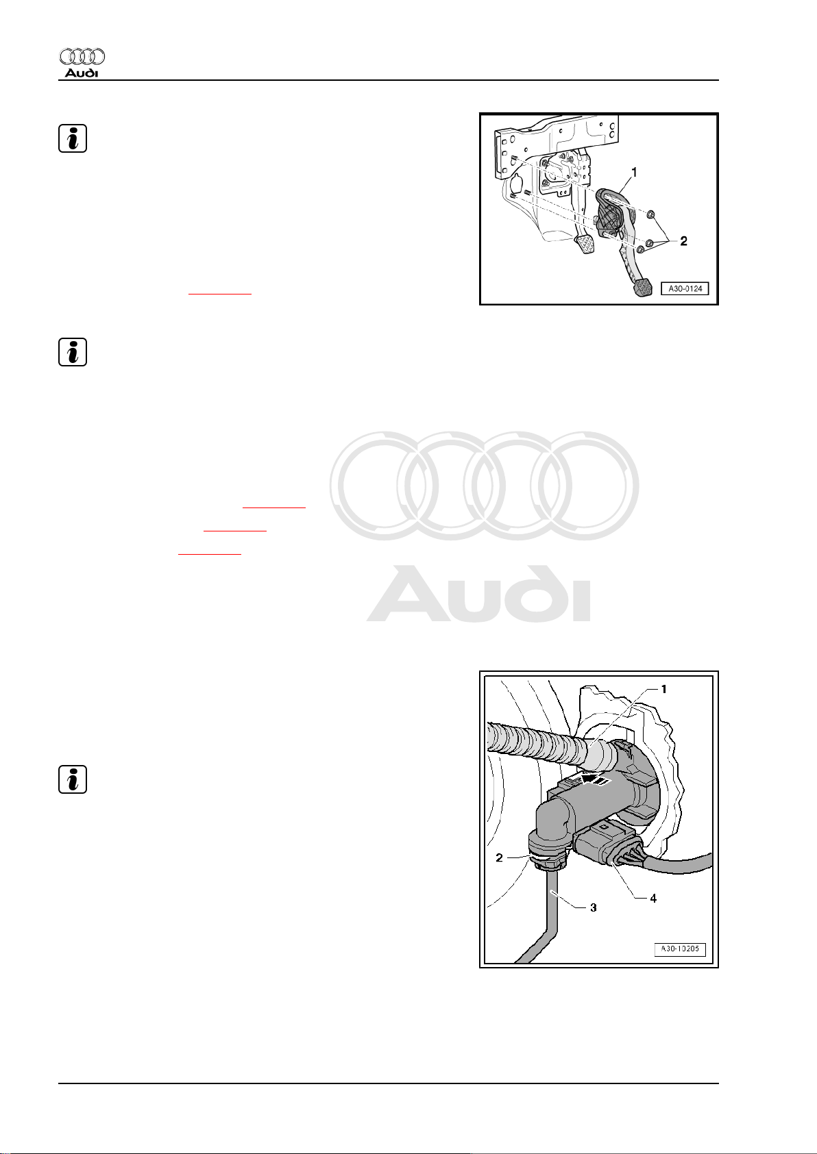
– Remove nuts -2-.
– Take out mounting bracket -1-.
Installing
• Tightening torque ⇒ page 12
Installation is carried out in reverse sequence; note the following:
Note
♦
Renew self-locking nuts.
♦
Renew O-rings
♦
Secure all hose connections with the correct hose clips (as
original equipment); refer to ⇒ Electronic parts catalogue .
– Fit mounting bracket -1- and tighten nuts -2-.
– Install pipe/hose assembly ⇒ page 25 .
– Bleed clutch system ⇒ page 28 .
– Install crash bar ⇒ page 13 .
– Install front footwell vent (left-side) ⇒ Rep. Gr. 80 .
– Install storage compartment on driver's side ⇒ Rep. Gr. 68 .
2.4 Removing and installing clutch position sender -G476-
Removing
– Unclip clutch position sender -G476- at clutch master cylinder
in direction of -arrow- and remove.
– Unplug electrical connector -4-.
Note
-Items 1, 2 and 3- can be disregarded.
20 Rep. Gr.30 - Clutch
Page 25
Protected by copyright. Copying for private or commercial purposes, in part or in whole, is not
permitted unless authorised by AUDI AG. AUDI AG does not guarantee or accept any liability
with respect to the correctness of information in this document. Copyright by AUDI AG.
6-speed manual gearbox 0A6, four-wheel drive - Edition 06.2009
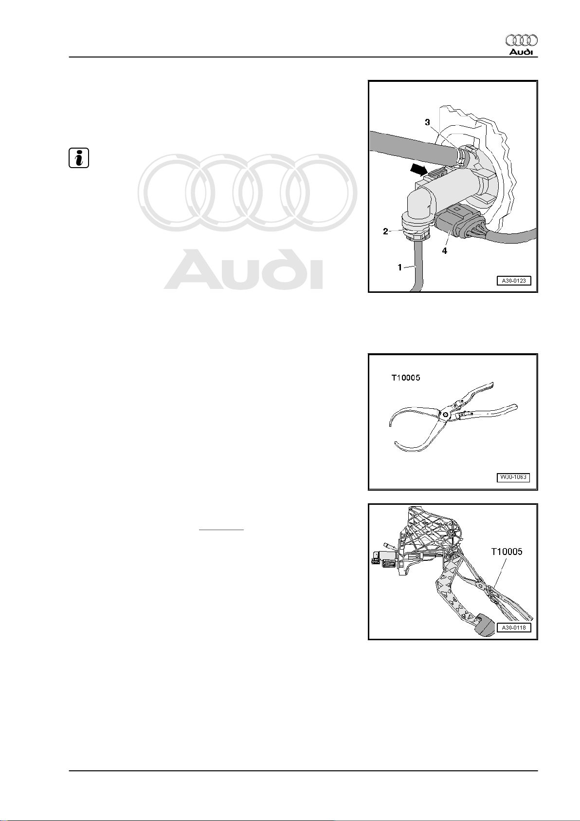
Installing
– Fit clutch position sender -G476- at clutch master cylinder and
engage -arrow-.
– Attach electrical connector -4-.
Note
-Items 1, 2 and 3- can be disregarded.
2.5 Removing and installing clutch master cylinder
Audi TT 2007 ➤
Special tools and workshop equipment required
♦ Pliers -T10005-
Removing
– Remove mounting bracket ⇒ page 18 .
– Release retaining clip for operating rod on clutch pedal using
pliers -T10005- .
2. Exploded view - pedal cluster, clutch master cylinder 21
Page 26
Protected by copyright. Copying for private or commercial purposes, in part or in whole, is not
permitted unless authorised by AUDI AG. AUDI AG does not guarantee or accept any liability
with respect to the correctness of information in this document. Copyright by AUDI AG.
Audi TT 2007 ➤
6-speed manual gearbox 0A6, four-wheel drive - Edition 06.2009
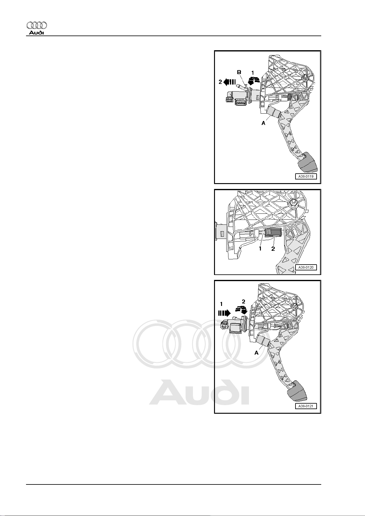
– Insert a spacer -A- between clutch pedal and stop, and press
clutch pedal forward.
•
Length of spacer = approx. 40 mm (e.g. 1/2” socket)
– Release retaining clip -B- and pull clutch master cylinder out
of mounting bracket -arrow 1- and -arrow 2-.
Installing
• Move clutch pedal back as far as stop until it is in normal po‐
sition.
– Install retaining clip -2- on operating rod -1- for clutch master
cylinder.
– Insert a spacer -A- between clutch pedal and stop, and press
clutch pedal forward.
•
Length of spacer = approx. 40 mm (e.g. 1/2” socket)
– Secure clutch master cylinder on mounting bracket -arrow 1-
and -arrow 2-.
22 Rep. Gr.30 - Clutch
Page 27
Protected by copyright. Copying for private or commercial purposes, in part or in whole, is not
permitted unless authorised by AUDI AG. AUDI AG does not guarantee or accept any liability
with respect to the correctness of information in this document. Copyright by AUDI AG.
6-speed manual gearbox 0A6, four-wheel drive - Edition 06.2009
– Press operating rod -1- for clutch master cylinder in direction
of -arrow- so that retaining clip -2- snaps into place in clutch
pedal.
– Install mounting bracket ⇒ page 18 .
Audi TT 2007 ➤
2. Exploded view - pedal cluster, clutch master cylinder 23
Page 28
Protected by copyright. Copying for private or commercial purposes, in part or in whole, is not
permitted unless authorised by AUDI AG. AUDI AG does not guarantee or accept any liability
with respect to the correctness of information in this document. Copyright by AUDI AG.
Audi TT 2007 ➤
6-speed manual gearbox 0A6, four-wheel drive - Edition 06.2009
3 Exploded view - hydraulics (LHD)
1 - Brake fluid reservoir
2 - Seal
❑ 2x
❑ Seals must be fitted in
supply hose
⇒ Item 3 (page 24)
3 - Supply hose
4 - Retaining clip
❑ To remove and install
retaining clip, first de‐
tach clutch master cylin‐
der from clutch pedal
⇒ page 15
5 - Clutch pedal
❑ Removing and installing
⇒ page 15
6 - Clutch master cylinder
❑ Removing and installing
⇒ page 21
7 - Clip
❑ To remove and install
pipe/hose assembly,
pull out clip as far as it
will go
8 - Nut
❑ For securing mounting
bracket to bulkhead
❑ Tightening torque
⇒ Item 15 (page 12)
9 - Seal or O-ring
❑ Renew damaged O-
rings
❑ Push onto pipe connection
❑ Lubricate with brake fluid before installing
❑ Whether a seal or an O-ring is used depends on the type of connection ⇒ page 25
❑ For correct version, refer to ⇒ Electronic parts catalogue
10 - Pipe/hose assembly
❑ Removing and installing ⇒ page 25
❑ For correct version, refer to ⇒ Electronic parts catalogue
11 - Bracket
❑ For pipe/hose assembly ⇒ Item 10 (page 24)
❑ Secured on body
12 - Seal or O-ring
❑ Renew damaged O-rings
❑ Push onto pipe connection
❑ Lubricate with brake fluid before installing
❑ Whether a seal or an O-ring is used depends on the type of connection ⇒ page 25
❑ For correct version, refer to ⇒ Electronic parts catalogue
24 Rep. Gr.30 - Clutch
Page 29
Protected by copyright. Copying for private or commercial purposes, in part or in whole, is not
permitted unless authorised by AUDI AG. AUDI AG does not guarantee or accept any liability
with respect to the correctness of information in this document. Copyright by AUDI AG.
Audi TT 2007 ➤
6-speed manual gearbox 0A6, four-wheel drive - Edition 06.2009
13 - Bleeder connection
14 - Seal or O-ring
❑ Renew damaged O-rings
❑ Push onto pipe connection
❑ Lubricate with brake fluid before installing
❑ Whether a seal or an O-ring is used depends on the type of connection ⇒ page 25
❑ For correct version, refer to ⇒ Electronic parts catalogue
15 - Clip
❑ To remove and install pipe/hose assembly or bleeder connection, pull out clip as far as it will go.
16 - Bleeder screw
❑ 4.5 Nm
❑ Bleeding clutch system ⇒ page 28
17 - Dust cap
18 - Clutch slave cylinder with release bearing
❑ Can only be renewed after removing gearbox
❑ Removing and installing ⇒ page 31
19 - Gearbox
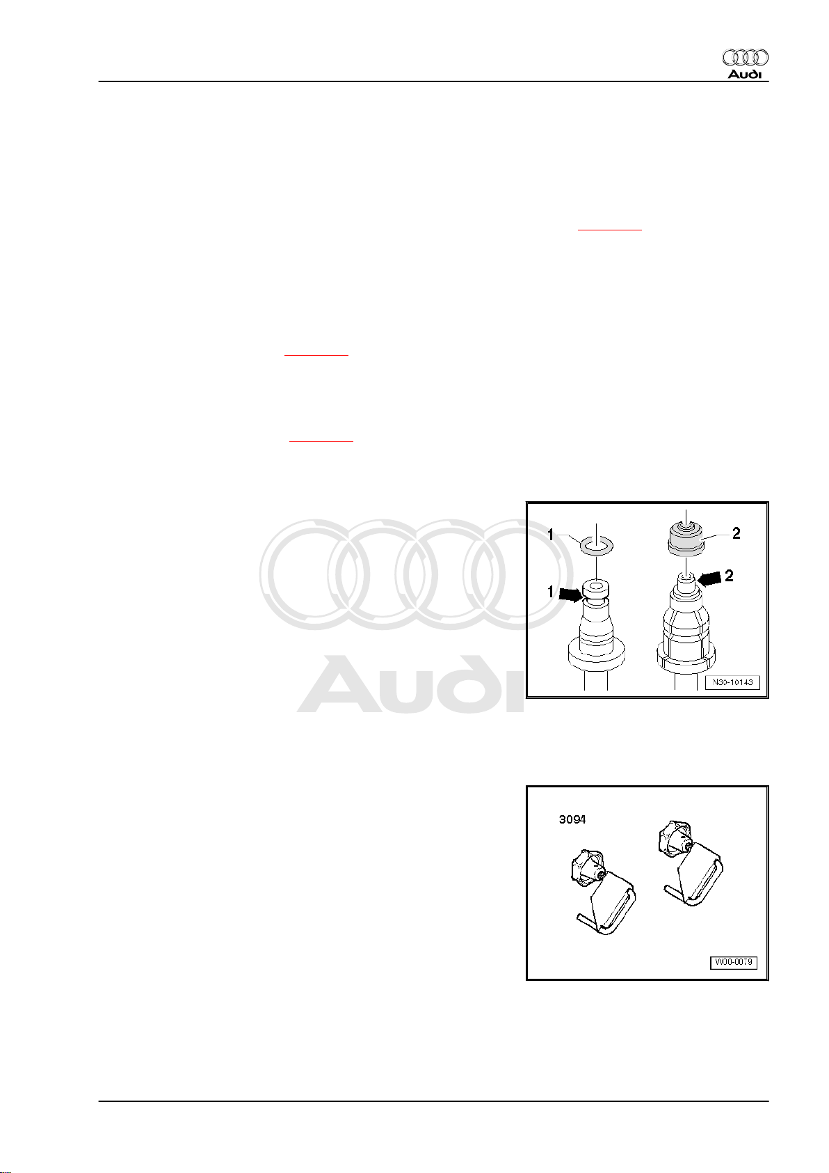
Seal/O-ring for pipe/hose assembly
1 - O-ring
♦ Connection with annular groove -arrow 1-
2 - Seal
♦ Connection with shoulder -arrow 2-
3.1 Removing and installing pipe/hose as‐
sembly
Special tools and workshop equipment required
♦ Hose clamps, up to Ø 25 mm -3094-
Removing
– Remove air cleaner housing completely ⇒ Rep. Gr. 24 .
3. Exploded view - hydraulics (LHD) 25
Page 30
Protected by copyright. Copying for private or commercial purposes, in part or in whole, is not
permitted unless authorised by AUDI AG. AUDI AG does not guarantee or accept any liability
with respect to the correctness of information in this document. Copyright by AUDI AG.
Audi TT 2007 ➤
6-speed manual gearbox 0A6, four-wheel drive - Edition 06.2009
Note
In the following steps make sure that no brake fluid escapes onto
the longitudinal member or onto the gearbox below. If this does
happen, clean the affected area thoroughly.
– Use hose clamp -3094- to clamp off supply hose to clutch
master cylinder.
Note
Place a cloth underneath to catch escaping brake fluid.
– Release retaining clip -3- on clutch master cylinder with a
screwdriver.
– Disconnect pipe/hose assembly -1- and detach from bracket.
Note
Place a cloth underneath to catch escaping brake fluid.
– Release retaining clip -2- on bleeder connection -1- with a
screwdriver and disconnect pipe/hose assembly -4-.
Installing
Installation is carried out in reverse sequence; note the following:
Note
For distinction between O-rings -2- and seals on different ver‐
sions, refer to ⇒ page 25 .
– Check O-ring -2- for damage and renew if necessary.
– Press pipe/hose assembly -1- onto connection on clutch mas‐
ter cylinder -4- so that retaining clip -3- snaps into place.
– Pull on pipe to check it is secure.
26 Rep. Gr.30 - Clutch
Page 31

Protected by copyright. Copying for private or commercial purposes, in part or in whole, is not
permitted unless authorised by AUDI AG. AUDI AG does not guarantee or accept any liability
with respect to the correctness of information in this document. Copyright by AUDI AG.
6-speed manual gearbox 0A6, four-wheel drive - Edition 06.2009
– Check O-ring -3- for damage and renew if necessary.
– Push pipe/hose assembly -4- into bleeder connection -1- so
that retaining clip -2- snaps into place.
– Pull on pipe to check it is secure.
– Bleed clutch system ⇒ page 28 .
3.2 Exploded view - hydraulics (RHD)
1 - Brake fluid reservoir
2 - Seal
❑ 2x
❑ Seals must be fitted in
supply hose
⇒ Item 3 (page 27)
3 - Supply hose
4 - Clutch master cylinder
❑
5 - Clip
❑ To remove and install
pipe, pull out clip as far
as it will go
6 - Seal or O-ring
❑ Renew damaged O-
rings
❑ Push onto pipe connec‐
tion
❑ Lubricate with brake flu‐
id before installing
❑ Whether a seal or an O-
ring is used depends on
the type of connection
⇒ page 25
❑ For correct version, re‐
fer to ⇒ Electronic parts
catalogue
7 - Retaining clip
❑ To remove and install
retaining clip first detach
master cylinder from
clutch pedal ⇒ page 15
8 - Clutch pedal
9 - Nut
❑ For securing mounting bracket to bulkhead
❑ Tightening torque ⇒ Item 15 (page 12)
10 - Bracket
❑ Secured on body
Audi TT 2007 ➤
3. Exploded view - hydraulics (LHD) 27
Page 32

Protected by copyright. Copying for private or commercial purposes, in part or in whole, is not
permitted unless authorised by AUDI AG. AUDI AG does not guarantee or accept any liability
with respect to the correctness of information in this document. Copyright by AUDI AG.
Audi TT 2007 ➤
6-speed manual gearbox 0A6, four-wheel drive - Edition 06.2009
11 - Pipe
❑ Can be combined as one unit with pipe/hose assembly ⇒ Item 13 (page 28) on some versions
❑ For correct version, refer to ⇒ Electronic parts catalogue
12 - Seal or O-ring
❑ Renew damaged O-rings
❑ Push onto pipe connection
❑ Lubricate with brake fluid before installing
❑ Whether a seal or an O-ring is used depends on the type of connection ⇒ page 25
❑ For correct version, refer to ⇒ Electronic parts catalogue
13 - Pipe/hose assembly
❑ Can be combined as one unit with pipe ⇒ Item 11 (page 27) on some versions
❑ For correct version, refer to ⇒ Electronic parts catalogue
14 - Seal or O-ring
❑ Renew damaged O-rings
❑ Push onto pipe connection
❑ Lubricate with brake fluid before installing
❑ Whether a seal or an O-ring is used depends on the type of connection ⇒ page 25
❑ For correct version, refer to ⇒ Electronic parts catalogue
15 - Clip
❑ To remove and install pipe/hose assembly or bleeder connection, pull out clip as far as it will go.
16 - Bleeder screw
❑ Bleeding clutch system ⇒ page 28
17 - Dust cap
18 - Bleeder connection
19 - Seal or O-ring
❑ Renew damaged O-rings
❑ Push onto pipe connection
❑ Lubricate with brake fluid before installing
❑ Whether a seal or an O-ring is used depends on the type of connection ⇒ page 25
❑ For correct version, refer to ⇒ Electronic parts catalogue
20 - Clutch slave cylinder with release bearing
❑ Can only be renewed after removing gearbox
❑ Removing and installing ⇒ page 31
21 - Gearbox
3.3 Bleeding clutch system
Note
♦
The clutch system must be bled after performing work on the
hydraulic clutch mechanism.
♦
In the following steps make sure that no brake fluid escapes
onto the longitudinal member or onto the gearbox below.
♦
Before bleeding clutch system, top up brake fluid reservoir to
“max.” marking with brake fluid.
Special tools and workshop equipment required
28 Rep. Gr.30 - Clutch
Page 33

Protected by copyright. Copying for private or commercial purposes, in part or in whole, is not
permitted unless authorised by AUDI AG. AUDI AG does not guarantee or accept any liability
with respect to the correctness of information in this document. Copyright by AUDI AG.
6-speed manual gearbox 0A6, four-wheel drive - Edition 06.2009
♦ Brake filling and bleeding equipment -VAS 5234-
♦ Brake fluid specification ⇒ Rep. Gr. 47.
Procedure
– Remove air cleaner housing completely ⇒ Rep. Gr. 24 .
– Pull clutch pedal back to its normal rest position.
– Connect brake filling and bleeding equipment -VAS 5234- to
brake fluid reservoir.
– Remove protective cap from bleeder screw -arrow- and con‐
nect hose -A- from bleeder bottle to bleeder screw.
– Switch on bleeding equipment.
• Operating pressure 2.0 bar
–
Now open bleeder screw approx 1/4 turn and allow 100 cm
of brake fluid to run out.
– With bleeder screw open, pump clutch pedal rapidly all the way
in and out by hand 15 to 20 times (approx. 2 times per second).
– Close bleeder screw. Tightening torque ⇒ Item 16 (page 25)
– Switch off brake filling and bleeding equipment -VAS 5234-
and release operating pressure (2.0 bar).
– Press clutch pedal slowly down with your foot 10 times and
check that clutch system is functioning properly.
– Remove brake filling and bleeding equipment -VAS 5234-
from brake fluid reservoir.
– Install air cleaner housing ⇒ Rep. Gr. 24 .
Audi TT 2007 ➤
3
3. Exploded view - hydraulics (LHD) 29
Page 34

Protected by copyright. Copying for private or commercial purposes, in part or in whole, is not
permitted unless authorised by AUDI AG. AUDI AG does not guarantee or accept any liability
with respect to the correctness of information in this document. Copyright by AUDI AG.
Audi TT 2007 ➤
6-speed manual gearbox 0A6, four-wheel drive - Edition 06.2009
4 Exploded view - clutch release mechanism, clutch slave cylinder
1 - Gearbox
2 - Input shaft oil seal
❑ Removing ⇒ page 116
❑ Driving in ⇒ page 116
3 - Clutch slave cylinder with
release bearing
❑ Are one unit; can only be
renewed together
❑ Do not wash out bear‐
ing; wipe clean only
❑ If bearing is noisy, re‐
new together with clutch
slave cylinder
❑ Tighten bolts carefully in
several small steps and
in diagonal sequence;
make sure that mount‐
ing lugs on clutch slave
cylinder do not break off
❑ For some slave cylin‐
ders, divided supply line
⇒ page 30
❑ Removing and installing
⇒ page 31
4 - Bolt
❑ Always renew
❑ 3x
❑ 15 Nm
5 - O-ring
❑ Renew if damaged
❑ Push onto pipe connec‐
tion
❑ Lubricate with brake flu‐
id before installing
Slave cylinder -A- with divided supply line
The supply line for some slave cylinders is divided in the area of
the -arrow-.
For correct version, refer to ⇒ Electronic parts catalogue
30 Rep. Gr.30 - Clutch
Page 35

Protected by copyright. Copying for private or commercial purposes, in part or in whole, is not
permitted unless authorised by AUDI AG. AUDI AG does not guarantee or accept any liability
with respect to the correctness of information in this document. Copyright by AUDI AG.
6-speed manual gearbox 0A6, four-wheel drive - Edition 06.2009
4.1 Removing and installing clutch slave cylinder with release bearing
Note
Clutch slave cylinder and release bearing are one unit and can
only be renewed together.
Removing
• Gearbox removed ⇒ page 61 .
– Release retaining clip -2- with a screwdriver and pull bleeder
connection -4- off clutch slave cylinder -1-.
Audi TT 2007 ➤
– Remove bolts -arrows-.
– Take off clutch slave cylinder together with release bearing
-A-.
Installing
• Tightening torque ⇒ page 30
Installation is carried out in reverse sequence; note the following:
Caution
Tighten securing bolts for clutch slave cylinder in small steps.
Otherwise mounting lugs -arrows- can be damaged.
– Secure clutch slave cylinder and release bearing -arrows-.
– Check O-ring -3- for damage and renew if necessary.
– Press bleeder connection -4- onto connection on clutch slave
cylinder -1- so that retaining clip -2- snaps into place.
– Pull on bleeder connection to check it is secure.
– Bleed clutch system ⇒ page 28 .
4. Exploded view - clutch release mechanism, clutch slave cylinder 31
Page 36

Protected by copyright. Copying for private or commercial purposes, in part or in whole, is not
permitted unless authorised by AUDI AG. AUDI AG does not guarantee or accept any liability
with respect to the correctness of information in this document. Copyright by AUDI AG.
Audi TT 2007 ➤
6-speed manual gearbox 0A6, four-wheel drive - Edition 06.2009
5 Exploded view - LuK version clutch
Note
♦
The dual-mass flywheel, pressure plate and clutch plate are matched together; components from another
manufacturer must not be installed on the same vehicle.
♦
Select the correct clutch plate and pressure plate according to engine code ⇒ Electronic parts catalogue .
1 - Dual-mass flywheel
❑ Removing and installing
⇒ Rep. Gr. 13
❑ Ensure that dowel pins
fit tightly
❑ Contact surface for
clutch lining must be
free of grooves, oil and
grease
❑ Observe instructions for
removal ⇒ page 33
2 - Clutch plate
❑ Removing and installing
⇒ page 33
❑ Always renew SAC
pressure plate as well
❑ Installation position:
marking
“Getriebeseite” (gear‐
box side) faces towards
gearbox
❑ For correct version, re‐
fer to ⇒ Electronic parts
catalogue
3 - SAC pressure plate
❑ “SAC” = self adjusting
clutch
❑ Always renew clutch
plate as well
❑ Removing and installing
⇒ page 33
❑ Checking position of ad‐
juster ring on new SAC
pressure plate
⇒ page 35
❑ Checking ends of diaphragm spring ⇒ page 35
❑ Checking spring connection and rivets ⇒ page 35
4 - Bolt
❑ M6 - 13 Nm
❑ M7 - 20 Nm
❑ Loosen and tighten bolts consecutively in steps of 90°
32 Rep. Gr.30 - Clutch
Page 37

Protected by copyright. Copying for private or commercial purposes, in part or in whole, is not
permitted unless authorised by AUDI AG. AUDI AG does not guarantee or accept any liability
with respect to the correctness of information in this document. Copyright by AUDI AG.
6-speed manual gearbox 0A6, four-wheel drive - Edition 06.2009
Instructions for removing dual-mass flywheel
Note
Do not use an impact wrench or pneumatic wrench to remove
bolts -B-: this would severely damage the dual-mass flywheel.
The bolts must always be removed by hand.
– Rotate dual-mass flywheel -A- so that the bolts are aligned
centrally behind the holes -arrows-.
– When removing the bolts, make sure that none of the bolt
heads contacts the dual-mass flywheel, as this would damage
the flywheel when the bolts are unscrewed further.
5.1 Removing and installing clutch
Special tools and workshop
equipment required
♦ Counterhold tool -3067-
♦ Centring mandrel -T10372-
♦ Torque wrench -V.A.G
1331-
♦ Grease for clutch plate
splines -G 000 100-
Audi TT 2007 ➤
5. Exploded view - LuK version clutch 33
Page 38

Protected by copyright. Copying for private or commercial purposes, in part or in whole, is not
permitted unless authorised by AUDI AG. AUDI AG does not guarantee or accept any liability
with respect to the correctness of information in this document. Copyright by AUDI AG.
Audi TT 2007 ➤
6-speed manual gearbox 0A6, four-wheel drive - Edition 06.2009
Removing
• Gearbox removed ⇒ page 61 .
– Apply counter-hold tool -3067- in order to loosen bolts.
To prevent the pressure plate from becoming distorted during re‐
moval (causes clutch grab when driving off), always adhere to the
following procedure when unbolting the pressure plate:
– Working clockwise, loosen all six bolts consecutively in steps
of 90° (1/4 turn) until the pressure plate is released.
– Take off pressure plate and clutch plate.
Installing
• Tightening torque ⇒ page 32
Installation is carried out in reverse sequence; note the following:
Note
♦
The dual-mass flywheel, pressure plate and clutch plate are
matched together; components from another manufacturer
must not be installed on the same vehicle.
♦
Always renew clutch plate and pressure plate together and
select the correct parts according to engine code ⇒ Electronic
parts catalogue .
♦
Checking position of adjuster ring on new pressure plate
⇒ page 35
♦
If the clutch has burnt out, thoroughly clean the clutch housing,
flywheel and parts of the engine facing the gearbox in order to
reduce the smell of burnt linings.
♦
Clean input shaft splines and (in the case of a used clutch
plate) the hub splines. Remove corrosion and apply only a very
thin coating of grease -G 000 100- to the splines. Then move
clutch plate backwards and forwards on input shaft until hub
moves freely on shaft. It is important to remove excess grease.
♦
Pressure plates have an anti-corrosion coating and are
greased. Only the contact surface may be cleaned, otherwise
the service life of the clutch will be considerably reduced.
♦
Pressure plate contact surface and clutch plate lining must
make full contact with flywheel. Only then insert bolts.
♦
Check that dowel sleeves for centralising engine/gearbox are
in the cylinder block; install if necessary.
♦
If the dowel sleeves are not fitted, this will lead to gear-change
problems, clutch malfunction and in some cases gearbox
noise (gears will make rattling noises).
34 Rep. Gr.30 - Clutch
Page 39

Protected by copyright. Copying for private or commercial purposes, in part or in whole, is not
permitted unless authorised by AUDI AG. AUDI AG does not guarantee or accept any liability
with respect to the correctness of information in this document. Copyright by AUDI AG.
6-speed manual gearbox 0A6, four-wheel drive - Edition 06.2009
Checking ends of diaphragm spring
• Wear up to half the thickness of the diaphragm spring
-arrows- is permissible.
Checking spring connections and rivets
– Check spring connections -arrows A- for damage and make
sure riveted joints -arrows B- are seated tightly.
• Renew pressure plate if spring connections are broken or bad‐
ly bent, or if riveted joints are loose.
Audi TT 2007 ➤
Checking position of adjustment mechanism (new SAC pressure
plates only)
• The two edges -A- of the adjuster ring should be located be‐
tween the two notches -arrows B-.
• If the adjuster ring is in a different position on a new pressure
plate, the pressure plate and clutch plate must not be installed.
• The position of the adjuster ring can be outside the notches
on used clutches.
Installation position of clutch plate:
• The marking “Getriebeseite” (gearbox side) faces towards the
gearbox
5. Exploded view - LuK version clutch 35
Page 40

Protected by copyright. Copying for private or commercial purposes, in part or in whole, is not
permitted unless authorised by AUDI AG. AUDI AG does not guarantee or accept any liability
with respect to the correctness of information in this document. Copyright by AUDI AG.
Audi TT 2007 ➤
6-speed manual gearbox 0A6, four-wheel drive - Edition 06.2009
– Use counter-hold tool -3067- .
– Fit pressure plate onto dowel pins.
– Use centring mandrel -T10097- to centralise clutch plate.
To prevent the pressure plate from becoming distorted during in‐
stallation (causes clutch grab when driving off), always adhere to
the following procedure when installing the pressure plate:
– Screw in all 6 bolts evenly by hand until bolt heads make con‐
tact with pressure plate.
– Working clockwise, tighten all six bolts consecutively in steps
of 90° (1/4 turn) until the housing makes contact with the fly‐
wheel.
– Working clockwise, tighten all 6 bolts to final torque consecu‐
tively. Tightening torque ⇒ Item 4 (page 32)
36 Rep. Gr.30 - Clutch
Page 41

Protected by copyright. Copying for private or commercial purposes, in part or in whole, is not
permitted unless authorised by AUDI AG. AUDI AG does not guarantee or accept any liability
with respect to the correctness of information in this document. Copyright by AUDI AG.
6-speed manual gearbox 0A6, four-wheel drive - Edition 06.2009
34 – Controls, housing
1 Overview - selector mechanism
♦ ⇒ “2 Exploded view - gear knob and covers”, page 39
♦ ⇒ “2.1 Removing and installing gear knob with gear lever boot
”, page 40
♦ ⇒ “3 Assembly overview - gear lever and selector housing”,
page 42
♦ ⇒ “3.1 Removing and installing selector mechanism”,
page 43
♦ ⇒ “3.2 Dismantling and assembling selector mechanism”,
page 46
♦ ⇒ “4 Exploded view - gear selector cable and gate selector
cable”, page 51
♦ ⇒ “4.1 Removing and installing gear selector cable and gate
selector cable”, page 52
♦ ⇒ “5 Exploded view - gearbox selector lever and gate relay
lever”, page 54
♦ ⇒ “6 Adjusting selector mechanism”, page 58
-Arrow A- gear selection movement
-Arrow B- gate selection movement
Audi TT 2007 ➤
1. Overview - selector mechanism 37
Page 42

Protected by copyright. Copying for private or commercial purposes, in part or in whole, is not
permitted unless authorised by AUDI AG. AUDI AG does not guarantee or accept any liability
with respect to the correctness of information in this document. Copyright by AUDI AG.
Audi TT 2007 ➤
6-speed manual gearbox 0A6, four-wheel drive - Edition 06.2009
A - Gear selector cable (gear
selection movement)
B - Gate selector cable (gate
selection movement)
C - Heat shield
❑ Remove before remov‐
ing selector mechanism
1 - Gearbox selector lever
2 - Gate relay lever
38 Rep. Gr.34 - Controls, housing
Page 43

Protected by copyright. Copying for private or commercial purposes, in part or in whole, is not
permitted unless authorised by AUDI AG. AUDI AG does not guarantee or accept any liability
with respect to the correctness of information in this document. Copyright by AUDI AG.
6-speed manual gearbox 0A6, four-wheel drive - Edition 06.2009
2 Exploded view - gear knob and covers
1 - Gear knob with gear lever
boot
❑ Cannot be separated
from each other
❑ Renew together
❑ Removing and installing
⇒ page 40
❑ Detaching from trim
panel for centre console
⇒ page 40
❑ Disconnecting from se‐
curing frame
⇒ page 40
2 - Clip
❑ Secures gear knob to
gear lever
❑ Secure with hose clip
pliers -V.A.G 1275-
3 - Trim panel for centre con‐
sole
❑ Remove and install to‐
gether with gear knob
⇒ page 40
❑ Detaching from gear
lever boot ⇒ page 40
4 - Securing frame
❑ Detaching from trim
panel for centre console
⇒ page 40
❑ Detaching from gear
lever boot ⇒ page 40
5 - Washer
❑ 4x
6 - Bolt
❑ 4x
❑ 1.5 Nm
7 - Noise insulation cover (upper)
8 - Noise insulation cover (lower)
9 - Gear lever
❑ Adjusting selector mechanism ⇒ page 58
Audi TT 2007 ➤
2. Exploded view - gear knob and covers 39
Page 44

Protected by copyright. Copying for private or commercial purposes, in part or in whole, is not
permitted unless authorised by AUDI AG. AUDI AG does not guarantee or accept any liability
with respect to the correctness of information in this document. Copyright by AUDI AG.
Audi TT 2007 ➤
6-speed manual gearbox 0A6, four-wheel drive - Edition 06.2009
Detaching trim panel for centre console and securing frame for
gear lever boot
– Remove bolts -arrows-.
– Detach trim panel from securing frame.
Detaching securing frame and gear lever boot
– Carefully release tabs -arrows- and lift securing frame -1- off
gear lever boot -2-.
2.1 Removing and installing gear knob with gear lever boot
Note
The gear knob is removed together with the gear lever boot and
the trim panel for the centre console.
Special tools and workshop equipment required
♦ Removal wedge -3409-
40 Rep. Gr.34 - Controls, housing
Page 45

Protected by copyright. Copying for private or commercial purposes, in part or in whole, is not
permitted unless authorised by AUDI AG. AUDI AG does not guarantee or accept any liability
with respect to the correctness of information in this document. Copyright by AUDI AG.
6-speed manual gearbox 0A6, four-wheel drive - Edition 06.2009
♦ Hose clip pliers -V.A.G 1275-
Removing
– Open ashtray.
– Carefully lever off trim panel from centre console -arrows-.
Audi TT 2007 ➤
– Unplug electrical connector at trim panel.
– Pull trim panel -3- up and over gear knob -2-.
– Open clip -1- and pull off gear knob together with gear lever
boot and trim panel -3-.
– Detach gear lever boot and trim panel for centre console -3-
⇒ page 40 .
Installing
Installation is carried out in reverse sequence; note the following:
– Push gear knob onto gear lever until it contacts stop.
– Secure gear knob to gear lever with a new clip -1-, using hose
clip pliers -V.A.G 1275- .
2. Exploded view - gear knob and covers 41
Page 46

Protected by copyright. Copying for private or commercial purposes, in part or in whole, is not
permitted unless authorised by AUDI AG. AUDI AG does not guarantee or accept any liability
with respect to the correctness of information in this document. Copyright by AUDI AG.
Audi TT 2007 ➤
6-speed manual gearbox 0A6, four-wheel drive - Edition 06.2009
3 Assembly overview - gear lever and selector housing
Note
Lubricate all bearings and moving surfaces with grease -G 000 450 02- .
1 - Floor plate
❑ Bend tabs open to re‐
move
❑ Renew
2 - Gasket
❑ Renew
3 - Gear lever
❑ Can be removed and in‐
stalled without removing
gear lever guide
-item 15-
4 - Damping washer
❑ Push onto gear lever as
far as stop -arrow-
5 - Securing clip
❑ Renew
6 - Gate selector cable
❑ Lever off gate selector
lever
❑ Press onto gate selector
lever inside selector
mechanism
❑ Installation position
⇒ page 37
7 - Bush
8 - Gear selector cable
❑ Lever off gear lever
guide
❑ Press onto gear lever
guide inside selector
mechanism
❑ Installation position
⇒ page 37
9 - Damper
10 - Ball socket
❑ Will be damaged during removal
❑ Renew
11 - Bush
12 - Securing clip
❑ Removing and installing ⇒ page 43
42 Rep. Gr.34 - Controls, housing
Page 47

Protected by copyright. Copying for private or commercial purposes, in part or in whole, is not
permitted unless authorised by AUDI AG. AUDI AG does not guarantee or accept any liability
with respect to the correctness of information in this document. Copyright by AUDI AG.
6-speed manual gearbox 0A6, four-wheel drive - Edition 06.2009
13 - Spring
14 - Bush
15 - Gear lever guide
16 - Nut
❑ 8 Nm
17 - Gasket
❑ Between selector housing and floor
❑ Self-adhesive
❑ Glue onto selector housing
18 - Selector housing
❑ With spring and gate selector lever
❑ Spring and gate selector lever cannot be detached
Removing securing clip
– Hold gear lever -2- firmly.
– Press spacer bush -3- in direction of -arrow- and remove se‐
curing clip -1-.
Audi TT 2007 ➤
3.1 Removing and installing selector mech‐
anism
Removing
– Remove gear knob together with trim panel for centre console
⇒ page 40 .
– Remove centre console ⇒ Rep. Gr. 68 .
– Remove noise insulation covers above selector mechanism.
– Remove nuts -arrows-.
3. Assembly overview - gear lever and selector housing 43
Page 48

Protected by copyright. Copying for private or commercial purposes, in part or in whole, is not
permitted unless authorised by AUDI AG. AUDI AG does not guarantee or accept any liability
with respect to the correctness of information in this document. Copyright by AUDI AG.
Audi TT 2007 ➤
6-speed manual gearbox 0A6, four-wheel drive - Edition 06.2009
– Remove air cleaner housing ⇒ Rep. Gr. 24 .
– Pull locking mechanism forwards -arrow 1- onto stop and then
turn to left -arrow 2- to lock.
– Press gate relay lever forwards -arrow 3- and pull gate selector
cable out of cable end-piece.
– Detach securing clip -1- for gear selector cable from gearbox
selector lever -2- and pull selector cable off pin -arrow-.
– Unscrew bolts -arrows-, remove cable support bracket from
gearbox and tie up on left side.
– Remove propshaft ⇒ Rear final drive 0BY; Rep. Gr. 39 .
44 Rep. Gr.34 - Controls, housing
Page 49

Protected by copyright. Copying for private or commercial purposes, in part or in whole, is not
permitted unless authorised by AUDI AG. AUDI AG does not guarantee or accept any liability
with respect to the correctness of information in this document. Copyright by AUDI AG.
6-speed manual gearbox 0A6, four-wheel drive - Edition 06.2009
– Remove bolts and nuts -arrows- and detach heat shield to‐
wards rear.
– Swing selector mechanism down and remove together with
selector cables.
Installing
Installation is carried out in reverse sequence; note the following:
• Tightening torques ⇒ page 42 , ⇒ page 51
Audi TT 2007 ➤
Note
Renew securing clip for gear selector cable.
– Fit selector mechanism and align parallel to body. Tighten nuts
-arrows-.
– Secure gear selector cable to gearbox selector lever
⇒ page 56 .
3. Assembly overview - gear lever and selector housing 45
Page 50

Protected by copyright. Copying for private or commercial purposes, in part or in whole, is not
permitted unless authorised by AUDI AG. AUDI AG does not guarantee or accept any liability
with respect to the correctness of information in this document. Copyright by AUDI AG.
Audi TT 2007 ➤
6-speed manual gearbox 0A6, four-wheel drive - Edition 06.2009
– Route cables -1- from selector mechanism -2- to gearbox as
follows:
• After the point where they cross over, the cables must run
parallel as far as the cable support bracket.
• The cables must be routed in the slot provided in heat shield
-3-.
Note
The enlargement shows the heat shield from above.
– Secure gear selector cable and gate selector cable with cable
tie -arrow- ⇒ page 52 .
– Adjust selector mechanism ⇒ page 58 .
– Fit noise insulation covers above selector mechanism and in‐
stall centre console ⇒ Rep. Gr. 68 .
– Install gear knob with gear lever boot ⇒ page 40 .
– Install air cleaner housing ⇒ Rep. Gr. 24 .
– Install propshaft ⇒ Rear final drive 0BY; Rep. Gr. 39 .
3.2 Dismantling and assembling selector
mechanism
Special tools and workshop equipment required
♦ Thrust block -T10083-
Dismantling
– Remove selector mechanism ⇒ page 43 .
– Open out tabs -arrows- all round with screwdriver and remove
floor plate.
– Detach gasket from selector mechanism.
– Remove gear selector cable and gate selector cable from se‐
lector housing ⇒ page 42 .
46 Rep. Gr.34 - Controls, housing
Page 51

Protected by copyright. Copying for private or commercial purposes, in part or in whole, is not
permitted unless authorised by AUDI AG. AUDI AG does not guarantee or accept any liability
with respect to the correctness of information in this document. Copyright by AUDI AG.
6-speed manual gearbox 0A6, four-wheel drive - Edition 06.2009
– Lift top spring arm -A- over tab on gate selector lever.
– Using a screwdriver, press lugs -arrows- on ball socket to‐
wards ball on gear lever guide; if necessary, break off lugs.
– Prise ball socket -A- out of selector housing together with gear
lever guide and gear lever -B-.
– Press ball socket off ball on gear lever guide and remove.
Audi TT 2007 ➤
Note
Note guides -A- when performing the following steps; they must
not be broken off.
– Lift bottom spring arm -arrow 1- onto stop on shoulder of gate
selector lever.
– Pull gear lever guide upwards as far as stop and pull ball-head
pin out of gate selector lever in direction of -arrow 2-.
3. Assembly overview - gear lever and selector housing 47
Page 52

Protected by copyright. Copying for private or commercial purposes, in part or in whole, is not
permitted unless authorised by AUDI AG. AUDI AG does not guarantee or accept any liability
with respect to the correctness of information in this document. Copyright by AUDI AG.
Audi TT 2007 ➤
6-speed manual gearbox 0A6, four-wheel drive - Edition 06.2009
– Turn gear lever guide anti-clockwise -arrow 1-.
• The pin -arrow 2- must be in the recess in the selector housing.
– Then swivel gear lever guide out in direction of -arrow 3- to‐
gether with gear lever.
Assembling
• Tightening torques ⇒ page 42
Note
Renew ball socket ⇒ Item 10 (page 42) .
Caution
Risk of accident.
♦ During the following steps, the bottom spring arm
(-arrow 1- ⇒ page 47 ) can become dislodged and snap
suddenly down off the shoulder of the gate selector lever.
– Carefully press bottom spring arm off shoulder of gate selector
lever.
• The spring arms will then compress “diagonally” (this will be
accompanied by a loud noise).
– Release the tension on spring arms -A- and -B- by turning
them both clockwise.
• Spring arms must point in opposite directions.
Note
The installation position is shown with the gear lever guide instal‐
led.
– Insert gear lever guide into selector housing together with gear
lever.
• Pin -arrow 1- should be positioned just inside recess on se‐
lector housing.
– Turn gear lever guide clockwise -arrow 2- until ball-head pin
-A- is above recess on selector housing.
48 Rep. Gr.34 - Controls, housing
Page 53

Protected by copyright. Copying for private or commercial purposes, in part or in whole, is not
permitted unless authorised by AUDI AG. AUDI AG does not guarantee or accept any liability
with respect to the correctness of information in this document. Copyright by AUDI AG.
6-speed manual gearbox 0A6, four-wheel drive - Edition 06.2009
– Insert selector housing with gear lever guide in larger recess
-arrow- in thrust block -T10083- .
• The gear lever guide should protrude out of the selector hous‐
ing as far as the stop.
– Insert arm -A- of spring in guide from above.
– Pull arm -B- of spring downwards and insert it next to the guide
(towards ball head).
Note
Audi TT 2007 ➤
For illustration purposes, only part of the gate selector lever is
shown.
– Carefully take selector housing off thrust block -T10083- to‐
gether with gear lever guide.
– Move gate selector lever back as far as stop (away from
mounting holes for gear selector cable and gate selector ca‐
ble) -arrow 1-.
– Grease ball-head pin and press it into gate selector lever
-arrow 2-.
• Guides -A- and tabs -B- must not be damaged.
– Insert selector housing with gear lever guide in larger recess
-arrow- in thrust block -T10083- .
3. Assembly overview - gear lever and selector housing 49
Page 54

Protected by copyright. Copying for private or commercial purposes, in part or in whole, is not
permitted unless authorised by AUDI AG. AUDI AG does not guarantee or accept any liability
with respect to the correctness of information in this document. Copyright by AUDI AG.
Audi TT 2007 ➤
6-speed manual gearbox 0A6, four-wheel drive - Edition 06.2009
• The gear lever guide should protrude out of the selector hous‐
ing as far as the stop.
– Lift top spring arm -A- over tab on gate selector lever.
– Grease ball socket -B- and ball of gear lever guide.
– Press ball socket onto ball of gear lever guide as far as stop.
– Remove selector housing from thrust block -T10083- .
– Press ball socket into selector housing in direction of
-arrows-.
• All four lugs must engage.
– Insert bottom spring arm -C- into guide.
– Lift top spring arm -A- over tab on gate selector lever and into
guide.
– Install selector mechanism ⇒ page 43 .
50 Rep. Gr.34 - Controls, housing
Page 55

Protected by copyright. Copying for private or commercial purposes, in part or in whole, is not
permitted unless authorised by AUDI AG. AUDI AG does not guarantee or accept any liability
with respect to the correctness of information in this document. Copyright by AUDI AG.
Audi TT 2007 ➤
6-speed manual gearbox 0A6, four-wheel drive - Edition 06.2009
4 Exploded view - gear selector cable and gate selector cable
Note
Lubricate all bearings and moving surfaces with grease -G 000 450 02- .
1 - Cable end-piece
❑ Secures gate selector
cable to gate relay lever
❑ Allocation ⇒ page 55
❑ Release to adjust selec‐
tor mechanism
⇒ page 59
2 - Cable support bracket
3 - Retaining clips
❑ Renew
4 - Retainer
5 - Gear selector cable
❑ Removing and installing
⇒ page 52
❑ Adjusting ⇒ page 58
6 - Gate selector cable
❑ Removing and installing
⇒ page 52
❑ Adjusting ⇒ page 58
7 - Retaining clips
❑ Renew
8 - Selector housing
9 - Clip
10 - Bolt
❑ 20 Nm
11 - Bolt
❑ 3.5 Nm
12 - Grommet
13 - Bush
14 - Cable end-piece
❑ Secures gear selector cable to gearbox selector lever
❑ Allocation ⇒ page 55
❑ Release to adjust selector mechanism ⇒ page 59
15 - Securing clip
4. Exploded view - gear selector cable and gate selector cable 51
Page 56

Protected by copyright. Copying for private or commercial purposes, in part or in whole, is not
permitted unless authorised by AUDI AG. AUDI AG does not guarantee or accept any liability
with respect to the correctness of information in this document. Copyright by AUDI AG.
Audi TT 2007 ➤
6-speed manual gearbox 0A6, four-wheel drive - Edition 06.2009
Securing gear selector cable and gate selector cable with cable
tie
– Wrap cable tie -arrow- in a figure-of-eight round gear selector
cable -A- and gate selector cable -B-.
– Secure cables as shown in illustration.
4.1 Removing and installing gear selector cable and gate selector cable
Removing
– Remove selector mechanism ⇒ page 43 .
– Open out tabs -arrows- on floor plate all round with screwdriver
and remove floor plate.
– Detach gasket from selector mechanism.
– Prise gear selector cable and gate selector cable off pins.
– Detach securing clips and remove gear selector cable and
gate selector cable from selector mechanism.
Release cable end-pieces -A- for gate selector cable and gear
selector cable -B- as follows:
– Push locking sleeve forwards onto stop -arrow 1- and turn fully
clockwise -arrow 2- so that it engages.
– Detach cable end-pieces from selector cables.
– Remove securing clips -1- and -2-.
– Detach cable support bracket from selector cables.
52 Rep. Gr.34 - Controls, housing
Page 57

Protected by copyright. Copying for private or commercial purposes, in part or in whole, is not
permitted unless authorised by AUDI AG. AUDI AG does not guarantee or accept any liability
with respect to the correctness of information in this document. Copyright by AUDI AG.
6-speed manual gearbox 0A6, four-wheel drive - Edition 06.2009
Installing
Note
Renew gasket and floor plate for selector housing.
– Secure gear selector cable and gate selector cable to selector
housing with securing clips -1 ... 4-.
– Secure gear selector cable and gate selector cable with cable
tie ⇒ page 52 .
– Press gear selector cable and gate selector cable onto pins.
The remaining installation steps are carried out in reverse se‐
quence; note the following:
– Install selector mechanism ⇒ page 43 .
– Adjust selector mechanism ⇒ page 58 .
Audi TT 2007 ➤
4. Exploded view - gear selector cable and gate selector cable 53
Page 58

Protected by copyright. Copying for private or commercial purposes, in part or in whole, is not
permitted unless authorised by AUDI AG. AUDI AG does not guarantee or accept any liability
with respect to the correctness of information in this document. Copyright by AUDI AG.
Audi TT 2007 ➤
6-speed manual gearbox 0A6, four-wheel drive - Edition 06.2009
5 Exploded view - gearbox selector lever and gate relay lever
Note
Lubricate all bearings and moving surfaces with grease -G 000 450 02- .
1 - Selector unit
❑ Servicing ⇒ page 117
2 - Gearbox selector lever
❑ With damper weight
❑ Fitting ⇒ page 55
❑ Installation position
⇒ page 55
❑ After installing, adjust
selector mechanism
⇒ page 58
3 - Clip
4 - Gate relay lever
❑ Installation position
⇒ page 55
❑ Detaching and securing
gate relay lever at gear‐
box selector lever
⇒ page 56
5 - Cable end-piece
❑ Secures gate selector
cable to gate relay lever
❑ Allocation ⇒ page 55
❑ Lever off to remove
⇒ page 57
❑ Pressing on
⇒ page 57
❑ Release to adjust selec‐
tor mechanism
⇒ page 59
6 - Slide block
7 - Nut
❑ 23 Nm
❑ Self-locking
❑ Renew
8 - Securing clip
❑ Renew
9 - Cable end-piece
❑ Secures gear selector cable to gearbox selector lever
❑ Allocation ⇒ page 55
❑ Release to adjust selector mechanism ⇒ page 59
10 - Oil seal
❑ Renewing ⇒ page 118
54 Rep. Gr.34 - Controls, housing
Page 59

Protected by copyright. Copying for private or commercial purposes, in part or in whole, is not
permitted unless authorised by AUDI AG. AUDI AG does not guarantee or accept any liability
with respect to the correctness of information in this document. Copyright by AUDI AG.
6-speed manual gearbox 0A6, four-wheel drive - Edition 06.2009
11 - Locking pin
❑ For adjusting selector mechanism ⇒ page 58
Installing gearbox selector lever
– When installing gearbox selector lever, make sure that the gap
in the splines -arrow A- aligns with the wider spline -arrow Bon the selector shaft.
Audi TT 2007 ➤
Installation position: gearbox selector lever/gate relay lever
1 - Gearbox selector lever with damper weight
2 - Gate relay lever locates in guide rail of gearbox selector lever
via slide block -arrow-
Identification of cable end-pieces
The holes in the cable end-pieces have different diameters.
Cable end-piece for: Dimension “a”
-1- Gear selector cable to gearbox selector lever 8.5 mm
-2- Gate selector cable to gate relay lever 10 mm
5. Exploded view - gearbox selector lever and gate relay lever 55
Page 60

Protected by copyright. Copying for private or commercial purposes, in part or in whole, is not
permitted unless authorised by AUDI AG. AUDI AG does not guarantee or accept any liability
with respect to the correctness of information in this document. Copyright by AUDI AG.
Audi TT 2007 ➤
6-speed manual gearbox 0A6, four-wheel drive - Edition 06.2009
Releasing cable end-piece from gate selector cable
– Pull locking mechanism forwards -arrow 1- onto stop and then
turn to left -arrow 2- to lock.
– Press gate relay lever forwards -arrow 3- and pull gate selector
cable out of cable end-piece.
Detaching and securing gear selector cable at gearbox selector
lever
Detaching
– Lift up tab and detach securing clip -1- for gear selector cable
from gearbox selector lever -2-.
– Pull gear selector cable off pin -arrow-.
Securing
Note
♦
Renew securing clip for gear selector cable.
♦
Apply a small quantity of grease -G 000 450 02- to the pin
-arrow-.
– Push gear selector cable onto gearbox selector lever -2- and
secure with securing clip -1-.
Detaching and securing gate relay lever at gearbox selector lever
Detaching
– Remove clip -arrow 1- and take off gate relay lever together
with cable end-piece.
Securing
Note
Lubricate all bearings and moving surfaces with grease -G 000
450 02- .
– Insert gate relay lever with cable end-piece as far as stop.
– Press on clip -arrow 1-, making sure it engages securely.
Note
-Arrow 2- can be disregarded.
56 Rep. Gr.34 - Controls, housing
Page 61

Protected by copyright. Copying for private or commercial purposes, in part or in whole, is not
permitted unless authorised by AUDI AG. AUDI AG does not guarantee or accept any liability
with respect to the correctness of information in this document. Copyright by AUDI AG.
6-speed manual gearbox 0A6, four-wheel drive - Edition 06.2009
Levering cable end-piece for gate selector cable off gate relay
lever
• Gate relay lever removed
– Apply plain slot screwdriver -A- between bush -B- and gate
relay lever.
Pressing cable end-piece for gate selector cable onto gate relay
lever
• Gate relay lever removed
• Press on cable end-piece only at bush -arrow-.
Audi TT 2007 ➤
• Cable end-piece must move freely on gate relay lever.
• Cable end-piece must be behind detent -arrow 2-.
– Ensure that components engage securely.
Note
-Arrow 1- can be disregarded.
5. Exploded view - gearbox selector lever and gate relay lever 57
Page 62

Protected by copyright. Copying for private or commercial purposes, in part or in whole, is not
permitted unless authorised by AUDI AG. AUDI AG does not guarantee or accept any liability
with respect to the correctness of information in this document. Copyright by AUDI AG.
Audi TT 2007 ➤
6-speed manual gearbox 0A6, four-wheel drive - Edition 06.2009
6 Adjusting selector mechanism
Special tools and workshop equipment required
♦ Locking pin -T10027 A-
Requirements for adjustment
• Gear selector linkage must be in proper condition and undam‐
aged.
• Selector mechanism must move freely.
• Gearbox, clutch and clutch mechanism must be in proper con‐
dition.
• Gearbox in neutral.
Adjusting
– Open ashtray.
– Carefully lever off trim panel from centre console -arrows-.
– Pull trim panel up and over gear knob.
– With gearbox in neutral, move gear lever to the left into 1st/
2nd gear gate.
– Lift noise insulation plate and lock gear lever in position with
locking pin -T10027 A- .
Note
The noise insulation covers are removed to give a better illustra‐
tion.
58 Rep. Gr.34 - Controls, housing
Page 63

Protected by copyright. Copying for private or commercial purposes, in part or in whole, is not
permitted unless authorised by AUDI AG. AUDI AG does not guarantee or accept any liability
with respect to the correctness of information in this document. Copyright by AUDI AG.
6-speed manual gearbox 0A6, four-wheel drive - Edition 06.2009
– Remove air cleaner housing ⇒ Rep. Gr. 24 .
Release cable end-pieces -A- for gate selector cable and gear
selector cable -B- as follows:
– Push locking sleeve forwards onto stop -arrow 1- and turn fully
clockwise -arrow 2- so that it engages.
• It should now be possible to move the selector cable in the
cable end-piece.
Audi TT 2007 ➤
Lock selector shaft as follows:
– Pull up selector shaft -arrow 1-.
– Press locking pin -A- inwards towards selector shaft
-arrow 2- and at the same time turn upwards -arrow 3- so it
engages in selector shaft.
– Check that gear selector cable and gate selector cable -B- are
located in cable end-pieces -A- without tension.
– Release locking sleeve -arrow 1- and let it slide onto stop
-arrow 2-.
• Cable adjustment is now complete.
6. Adjusting selector mechanism 59
Page 64

Protected by copyright. Copying for private or commercial purposes, in part or in whole, is not
permitted unless authorised by AUDI AG. AUDI AG does not guarantee or accept any liability
with respect to the correctness of information in this document. Copyright by AUDI AG.
Audi TT 2007 ➤
6-speed manual gearbox 0A6, four-wheel drive - Edition 06.2009
– Turn locking pin -A- back to initial position -arrow 2- and pull
out of gearbox -arrow 1-.
– Pull locking pin -T10027 A- out of selector mechanism.
Checking gear lever setting
• With the gearbox in neutral, the gear lever should rest in the
3rd/4th gear gate.
– Depress clutch.
– Select all gears several times. Pay particular attention to the
operation of the reverse gear locking mechanism.
If the gear lever sticks or baulks repeatedly when engaging a
gear, perform the adjustment procedure again.
– Fit gear lever boot and trim panel for centre console.
– Install air cleaner housing ⇒ Rep. Gr. 24 .
60 Rep. Gr.34 - Controls, housing
Page 65

Protected by copyright. Copying for private or commercial purposes, in part or in whole, is not
permitted unless authorised by AUDI AG. AUDI AG does not guarantee or accept any liability
with respect to the correctness of information in this document. Copyright by AUDI AG.
6-speed manual gearbox 0A6, four-wheel drive - Edition 06.2009
7 Removing and installing gearbox
General view
♦ ⇒ “7.1 Removing gearbox - vehicles with 2.5 ltr. TFSI engine”,
page 61
♦ ⇒ “7.2 Installing gearbox”, page 70
7.1 Removing gearbox - vehicles with 2.5 ltr. TFSI engine
Audi TT 2007 ➤
Special tools and workshop equipment required
♦ Support bracket -10 - 222 A-
♦ Hose clamps, up to 25 mm -3094-
♦ Gearbox support -3282-
♦ Pin -3282/34-
♦ Adjustment plate -3282/60-
♦ Engine and gearbox jack -V.A.G 1383 A-
7. Removing and installing gearbox 61
Page 66

Protected by copyright. Copying for private or commercial purposes, in part or in whole, is not
permitted unless authorised by AUDI AG. AUDI AG does not guarantee or accept any liability
with respect to the correctness of information in this document. Copyright by AUDI AG.
Audi TT 2007 ➤
6-speed manual gearbox 0A6, four-wheel drive - Edition 06.2009
♦ Engine bung set -VAS 6122-
♦ Grease -G 000 450 02-
♦ Grease for clutch plate splines -G 000 100-
Procedure
Caution
When disconnecting the battery there is a risk of serious dam‐
age to electronic components:
♦ Observe the correct procedure for disconnecting the bat‐
tery.
– With ignition switched off, disconnect battery earth cable
-arrow- ⇒ Rep. Gr. 27 .
– Remove starter ⇒ Rep. Gr. 27 .
– Remove nuts -1- and detach heat shield for drive shaft (right-
side).
– Remove drive shafts on both sides ⇒ Rep. Gr. 40 .
62 Rep. Gr.34 - Controls, housing
Page 67

Protected by copyright. Copying for private or commercial purposes, in part or in whole, is not
permitted unless authorised by AUDI AG. AUDI AG does not guarantee or accept any liability
with respect to the correctness of information in this document. Copyright by AUDI AG.
6-speed manual gearbox 0A6, four-wheel drive - Edition 06.2009
– Remove steering box with subframe ⇒ Rep. Gr. 48 .
– Remove coolant pipe (left-side) ⇒ Rep. Gr. 19 .
Audi TT 2007 ➤
– Remove vibration damper ⇒ Rep. Gr. 13 .
7. Removing and installing gearbox 63
Page 68

Protected by copyright. Copying for private or commercial purposes, in part or in whole, is not
permitted unless authorised by AUDI AG. AUDI AG does not guarantee or accept any liability
with respect to the correctness of information in this document. Copyright by AUDI AG.
Audi TT 2007 ➤
6-speed manual gearbox 0A6, four-wheel drive - Edition 06.2009
– Release hose clip -2-.
Note
-Items 1 and 3- can be disregarded.
– Remove bolt -4- for earth wire.
– Unplug electrical connector -3- for reversing light switch -F4- .
Note
-Items 1 and 2- can be disregarded.
• To avoid damage to the gate selector cable, the cable endpiece must be separated from the gate selector cable before
removal.
– Pull locking mechanism forwards -arrow 1- onto stop and then
turn to left -arrow 2- to lock.
– Press gate relay lever forwards -arrow 3- and pull gate selector
cable out of cable end-piece.
– Detach securing clip -1- for gear selector cable from gearbox
selector lever -2- and pull selector cable off pin -arrow-.
64 Rep. Gr.34 - Controls, housing
Page 69

Protected by copyright. Copying for private or commercial purposes, in part or in whole, is not
permitted unless authorised by AUDI AG. AUDI AG does not guarantee or accept any liability
with respect to the correctness of information in this document. Copyright by AUDI AG.
6-speed manual gearbox 0A6, four-wheel drive - Edition 06.2009
– Unscrew bolts -arrows-, remove cable support bracket from
gearbox and tie up on left side.
– If a plastic pipe is installed between clutch master cylinder and
slave cylinder, clamp off supply hose to clutch master cylinder
using hose clamp -3094- .
Audi TT 2007 ➤
– If a pipe/hose assembly is installed between clutch master
cylinder and slave cylinder, clamp off hose -A- using hose
clamp -3094- .
Note
♦
-Arrow- can be disregarded.
♦
In the following steps make sure that no brake fluid escapes
onto the starter or onto the gearbox below. If this does happen,
clean the affected area thoroughly.
– Pull clip -arrow- out as far as stop.
– Pull plastic pipe or pipe/hose assembly -A- out of bleeder con‐
nection for clutch slave cylinder.
– Seal off open lines and connections with clean plugs from en‐
gine bung set -VAS 6122- .
Note
-Item B- can be disregarded.
Caution
Catch escaping brake fluid.
♦ Do not operate clutch pedal after detaching pipe from
bleeder connection for clutch slave cylinder.
7. Removing and installing gearbox 65
Page 70

Protected by copyright. Copying for private or commercial purposes, in part or in whole, is not
permitted unless authorised by AUDI AG. AUDI AG does not guarantee or accept any liability
with respect to the correctness of information in this document. Copyright by AUDI AG.
Audi TT 2007 ➤
6-speed manual gearbox 0A6, four-wheel drive - Edition 06.2009
– Set up support bracket -10 - 222 A- on body flanges using the
following equipment:
♦ Rack -10 - 222 A /1- (2x)
♦ Adapter -10 - 222 A /3-
♦ 2x spindle -10 - 222 A /11-
♦ Adapter -10 - 222 A /20-
• One spindle -10 - 222 A /11- faces forward, the other to the
rear.
WARNING
Risk of accident.
♦ The hook attachment and locating pin on the lifting tackle
must be secured with a locking pin -arrows-.
– Hook front spindle -10 - 222 A /11- with adapter -10 - 222 A /
20- onto engine lifting eye (front left).
– Hook rear spindle -10 - 222 A /11- onto engine lifting eye (rear
left).
– Remove bolts -1- securing gearbox to engine.
– Remove bolts -arrows- from gearbox mounting.
66 Rep. Gr.34 - Controls, housing
Page 71

Protected by copyright. Copying for private or commercial purposes, in part or in whole, is not
permitted unless authorised by AUDI AG. AUDI AG does not guarantee or accept any liability
with respect to the correctness of information in this document. Copyright by AUDI AG.
6-speed manual gearbox 0A6, four-wheel drive - Edition 06.2009
– Detach air intake grille -1- from bumper cover in direction of
-arrow-.
– Unscrew bolt -1- and detach air duct.
Note
-Item 2- can be disregarded.
Audi TT 2007 ➤
– Remove bolt -1-.
– Release hose clip -2- and detach air pipe.
– Mark position of flexible coupling relative to bevel box flange
for re-installation.
– Engage a gear and remove bolts -arrow- for flexible coupling
on propshaft.
7. Removing and installing gearbox 67
Page 72

Protected by copyright. Copying for private or commercial purposes, in part or in whole, is not
permitted unless authorised by AUDI AG. AUDI AG does not guarantee or accept any liability
with respect to the correctness of information in this document. Copyright by AUDI AG.
Audi TT 2007 ➤
6-speed manual gearbox 0A6, four-wheel drive - Edition 06.2009
Caution
Risk of damage to seal -arrow- in propshaft flange.
♦ Push propshaft as far back as possible, while keeping it
horizontal.
Note
If seal is damaged propshaft must be renewed.
– Remove bolts -1- and -2- and detach bracket for starter cata‐
lytic converter.
Note
-Item 3- can be disregarded.
– Remove bolts -1- and -2-.
– Release hose clips -arrows- and detach air pipe.
– Remove bolts -1, 2, 3- and detach bracket for bevel box.
68 Rep. Gr.34 - Controls, housing
Page 73

Protected by copyright. Copying for private or commercial purposes, in part or in whole, is not
permitted unless authorised by AUDI AG. AUDI AG does not guarantee or accept any liability
with respect to the correctness of information in this document. Copyright by AUDI AG.
6-speed manual gearbox 0A6, four-wheel drive - Edition 06.2009
– Adjust spindles of support bracket -10 - 222 A- to lower gear‐
box by distance -a-.
• Dimension -a- = 80 mm
Set up gearbox support -3282- with adjustment plate -3282/60to remove gearbox “0A6”.
– Insert gearbox support -3282- in engine and gearbox jack -
V.A.G 1383 A- .
– Align arms of gearbox support according to holes in adjust‐
ment plate.
– Screw in support elements -A-, as illustrated on adjustment
plate -3282/60- .
– In place of support element -C-, screw in bolt -3282/34- .
– Place engine and gearbox jack -V.A.G 1383 A- underneath
vehicle.
• Arrow symbol -B- on adjustment plate points to front of vehicle.
– Align adjustment plate and gearbox parallel to one another.
Audi TT 2007 ➤
– Screw pin -3282/34- into hole for bolt securing pendulum sup‐
port to gearbox.
7. Removing and installing gearbox 69
Page 74

Protected by copyright. Copying for private or commercial purposes, in part or in whole, is not
permitted unless authorised by AUDI AG. AUDI AG does not guarantee or accept any liability
with respect to the correctness of information in this document. Copyright by AUDI AG.
Audi TT 2007 ➤
6-speed manual gearbox 0A6, four-wheel drive - Edition 06.2009
– Remove remaining engine/gearbox securing bolts.
– Push gearbox off dowel sleeves -A, B-.
– Tilt gearbox to left using spindles of gearbox support -3282- .
– Lower gearbox carefully, observing longitudinal member.
Note
Pay attention to all pipes/hoses/wiring when lowering gearbox.
7.2 Installing gearbox
Installation is carried out in reverse sequence; note the following:
Note
♦
Renew self-locking nuts and bolts when performing assembly
work.
♦
Renew oil seals, gaskets, O-rings and bolts which are tight‐
ened by turning through a specified angle.
♦
All cable ties which are released or cut open during removal
must be fitted in the same position when installing.
♦
Clean input shaft splines and (in the case of a used clutch
plate) the hub splines. Remove corrosion and apply only a very
thin coating of grease for clutch plate splines -G 000 100- to
the splines. Then move clutch plate backwards and forwards
on input shaft until hub moves freely on shaft. It is important
to remove excess grease.
♦
When installing a new gearbox, the gear selector lever and
gate relay lever must be transferred to the new unit.
– Use thread tap to remove any remaining locking fluid from all
threaded holes which will accommodate self-locking bolts.
– If no dowel sleeves -A, B- for centralising engine/gearbox are
in the cylinder block, install dowel sleeves.
– Check centring of clutch plate ⇒ page 33 .
– Check release bearing for wear; if necessary, renew clutch
slave cylinder with release bearing ⇒ page 30 .
– Raise gearbox carefully using gearbox support -3282- .
– Align gearbox with engine and install.
Note
Pay attention to all pipes/hoses/wiring when installing the gear‐
box.
– Screw in and tighten bottom engine/gearbox securing bolts
-1 … 5- first, then remaining securing bolts ⇒ page 72 .
70 Rep. Gr.34 - Controls, housing
Page 75

Protected by copyright. Copying for private or commercial purposes, in part or in whole, is not
permitted unless authorised by AUDI AG. AUDI AG does not guarantee or accept any liability
with respect to the correctness of information in this document. Copyright by AUDI AG.
6-speed manual gearbox 0A6, four-wheel drive - Edition 06.2009
– Align engine/gearbox in installation position. To do so, tighten
spindles of support bracket -10 - 222 A- until gearbox makes
contact with gearbox mounting.
Note
The gearbox mounting must be parallel with the gearbox to avoid
causing damage to the threads in the gearbox.
– Install gearbox mounting ⇒ page 75 .
Note
When installing gearbox ensure engine/gearbox mountings are
installed stress-free ⇒ Rep. Gr. 10 .
Caution
Risk of accident.
Audi TT 2007 ➤
♦ Do not remove support bracket -10 - 222 A- until all bolts
securing the left-hand engine/gearbox mounting have
been tightened to the specified torque.
– Install bracket for bevel box ⇒ page 73 .
– Install drive shafts (left and right) ⇒ Rep. Gr. 40 .
– Install heat shield for drive shaft (right-side) ⇒ page 73 .
Caution
Risk of damage to seal -arrow- in propshaft flange.
♦ Push propshaft as far back as possible, while keeping it
horizontal.
Note
If seal is damaged propshaft must be renewed.
– Press engine/gearbox assembly towards bulkhead, guiding
pin on bevel box carefully into propshaft flange.
7. Removing and installing gearbox 71
Page 76

Protected by copyright. Copying for private or commercial purposes, in part or in whole, is not
permitted unless authorised by AUDI AG. AUDI AG does not guarantee or accept any liability
with respect to the correctness of information in this document. Copyright by AUDI AG.
Audi TT 2007 ➤
6-speed manual gearbox 0A6, four-wheel drive - Edition 06.2009
– Bolt flexible coupling on propshaft onto bevel box flange
-arrows- ⇒ Rear final drive 02D, 0AV, 0BR and 0BY; Rep. Gr.
39 .
– Install pendulum support ⇒ page 75 .
– Install vibration damper ⇒ Rep. Gr. 13 .
– Install coolant pipe (left-side) ⇒ Rep. Gr. 19 .
– Install steering box with subframe ⇒ Rep. Gr. 48 .
– Install drive shafts ⇒ Rep. Gr. 40 .
– Install exhaust system and cross piece ⇒ Rep. Gr. 26 .
– Install radiator cowl ⇒ Rep. Gr. 19 .
– Install starter ⇒ Rep. Gr. 27 .
– Install pipe/hose assembly or plastic pipe ⇒ page 25 .
– Bleed clutch system ⇒ page 28 .
– Install cable support bracket ⇒ page 51 .
– Secure gear selector cable to gearbox selector lever
⇒ page 56 .
– Insert gate selector cable in cable end-piece.
– Adjust selector mechanism ⇒ page 58 .
– Install air cleaner housing ⇒ Rep. Gr. 24 .
– Observe correct procedure after connecting battery ⇒ Rep.
Gr. 27 .
– Install front sections of wheel housing liners ⇒ Rep. Gr. 66 .
– Install noise insulation frame ⇒ Rep. Gr. 50 .
– Install noise insulation ⇒ Rep. Gr. 66 .
– Fit wheels ⇒ Rep. Gr. 44 .
– Check gear oil level in gearbox ⇒ page 85 .
– Check gear oil level in bevel box ⇒ page 86 .
Tightening torques (installing gearbox)
Note
♦
Tightening torques apply only to lightly greased, oiled,
phosphated or black-finished nuts and bolts.
♦
Additional lubricant such as engine or gear oil may be used,
but do not use graphite lubricant.
♦
Do not use parts which have been degreased.
♦
Tolerance for tightening torques ±15%.
72 Rep. Gr.34 - Controls, housing
Page 77

Protected by copyright. Copying for private or commercial purposes, in part or in whole, is not
permitted unless authorised by AUDI AG. AUDI AG does not guarantee or accept any liability
with respect to the correctness of information in this document. Copyright by AUDI AG.
6-speed manual gearbox 0A6, four-wheel drive - Edition 06.2009
Engine/gearbox securing bolts
Item Bolt Nm
1 M12x65 80
2
1)
M12x180 80
3 M10x65 40
4 M10x75 40
5
2)
M12x95 80
A, B Dowel sleeves for centralising
1)
•
Bolt with stud M8.
2)
•
Screwed into gearbox from engine side.
Bracket for bevel box - tightening torque and sequence
– Tighten bolts in 5 stages as follows:
1. Screw in bolts -1 ... 3- (hand-tight).
2. Pre-tighten bolts -2- to 8 Nm.
Audi TT 2007 ➤
3. Tighten bolts -1- and -3- initially to 8 Nm.
4. Tighten bolts -2- to 40 Nm.
5. Tighten bolts -1- and -3- to 40 Nm.
Heat shield for drive shaft (right-side) - tightening torque
– Tighten nuts -1- to 25 Nm.
7. Removing and installing gearbox 73
Page 78

Protected by copyright. Copying for private or commercial purposes, in part or in whole, is not
permitted unless authorised by AUDI AG. AUDI AG does not guarantee or accept any liability
with respect to the correctness of information in this document. Copyright by AUDI AG.
Audi TT 2007 ➤
6-speed manual gearbox 0A6, four-wheel drive - Edition 06.2009
8 Transporting gearbox
Special tools and workshop equipment required
♦ Shackle -10-222A/12-
♦ Hook -10-222A/2-
♦ Workshop hoist -VAS 6100-
Shackle -10-222A/12- may be used in conjunction with hook
-10-222A/2- and a workshop hoist to transport the gearbox and
to set up gearbox support -3282- .
– Secure shackle -10-222A/12- to gearbox housing.
– Lift gearbox using workshop hoist and hook -10-222A/2- .
74 Rep. Gr.34 - Controls, housing
Page 79

Protected by copyright. Copying for private or commercial purposes, in part or in whole, is not
permitted unless authorised by AUDI AG. AUDI AG does not guarantee or accept any liability
with respect to the correctness of information in this document. Copyright by AUDI AG.
6-speed manual gearbox 0A6, four-wheel drive - Edition 06.2009
9 Exploded view - assembly mountings
1 - Bolt
❑ Engine mounting to en‐
gine
❑ Tightening torque ⇒
Rep. Gr. 10
2 - Bolt
❑ Engine mounting to en‐
gine
❑ Tightening torque ⇒
Rep. Gr. 10
3 - Bolt
❑ Engine mounting to
body
❑ Tightening torque ⇒
Rep. Gr. 10
4 - Bracket
❑ For activated charcoal
filter
5 - Bolt
❑ Tightening torque ⇒
Rep. Gr. 10
6 - Nut
❑ Tightening torque ⇒
Rep. Gr. 10
7 - Engine mounting
❑ Checking adjustment ⇒
Rep. Gr. 10
❑ Adjusting ⇒ Rep. Gr. 10
❑ Removing and installing
⇒ Rep. Gr. 10
8 - Connecting bracket
9 - Bolt
❑ Connecting bracket to body
❑ Tightening torque ⇒ Rep. Gr. 10
10 - Bolt
❑ Connecting bracket to engine mounting
❑ Tightening torque ⇒ Rep. Gr. 10
11 - Bolt
❑ Engine mounting to body
❑ Tightening torque ⇒ Rep. Gr. 10
Audi TT 2007 ➤
12 - Pendulum support
❑ Removing and installing ⇒ page 79
13 - Bolt
❑ Pendulum support to subframe
❑ 100 Nm + 90°
❑ Always renew
9. Exploded view - assembly mountings 75
Page 80

Protected by copyright. Copying for private or commercial purposes, in part or in whole, is not
permitted unless authorised by AUDI AG. AUDI AG does not guarantee or accept any liability
with respect to the correctness of information in this document. Copyright by AUDI AG.
Audi TT 2007 ➤
6-speed manual gearbox 0A6, four-wheel drive - Edition 06.2009
14 - Bolt
❑ Pendulum support to gearbox
❑ 60 Nm +90°
❑ Always renew
15 - Bolt
❑ Pendulum support to gearbox
❑ 60 Nm +90°
❑ Always renew
16 - Bolt
❑ Gearbox mounting to gearbox
❑ 60 Nm +90°
❑ Always renew
17 - Bolt
❑ Gearbox mounting to body
❑ 40 Nm +90°
❑ Always renew
18 - Gearbox mounting
❑ Checking adjustment ⇒ Rep. Gr. 10
❑ Adjusting ⇒ Rep. Gr. 10
❑ Removing and installing ⇒ page 76
9.1 Removing and installing gearbox mounting
Special tools and workshop equipment required
♦ Support bracket -10-222 A-
♦ Hooks -10 - 222 A /20-
76 Rep. Gr.34 - Controls, housing
Page 81

Protected by copyright. Copying for private or commercial purposes, in part or in whole, is not
permitted unless authorised by AUDI AG. AUDI AG does not guarantee or accept any liability
with respect to the correctness of information in this document. Copyright by AUDI AG.
6-speed manual gearbox 0A6, four-wheel drive - Edition 06.2009
Removing
– Lift off engine cover panel -1- -arrows-.
– Remove air cleaner housing ⇒ Rep. Gr. 24 .
Audi TT 2007 ➤
– Open retainers for wiring duct -arrows-.
– Cut through cable tie and press electrical wiring to one side.
– Unclip wiring duct.
9. Exploded view - assembly mountings 77
Page 82

Protected by copyright. Copying for private or commercial purposes, in part or in whole, is not
permitted unless authorised by AUDI AG. AUDI AG does not guarantee or accept any liability
with respect to the correctness of information in this document. Copyright by AUDI AG.
Audi TT 2007 ➤
6-speed manual gearbox 0A6, four-wheel drive - Edition 06.2009
– Set up support bracket -10 - 222 A- on body flanges using the
following equipment:
♦ Rack -10 - 222 A /1- (2x)
♦ Adapter -10 - 222 A /3-
♦ 2x spindle -10 - 222 A /11-
♦ Hooks -10 - 222 A /20-
• One spindle -10 - 222 A /11- faces forward, the other to the
rear.
WARNING
Risk of accident.
♦ The hook attachments and locating pins on the lifting tack‐
le must be secured with a locking pin -arrows-.
– Hook front spindle -10 - 222 A /11- with hook -10 - 222 A /20-
onto engine lifting eye (front left).
– Hook rear spindle -10 - 222 A /11- onto engine lifting eye (rear
left).
– Apply light tension to spindles.
– Remove bolts -arrows- from gearbox mounting.
– Remove bolts -1- and detach gearbox mounting -A-.
Installing
• Tightening torques
⇒ “9 Exploded view - assembly mountings”, page 75
Installation is carried out in reverse sequence; note the following:
– Adjust assembly mountings ⇒ Rep. Gr. 10 .
– Install air cleaner housing ⇒ Rep. Gr. 24 .
78 Rep. Gr.34 - Controls, housing
Page 83

Protected by copyright. Copying for private or commercial purposes, in part or in whole, is not
permitted unless authorised by AUDI AG. AUDI AG does not guarantee or accept any liability
with respect to the correctness of information in this document. Copyright by AUDI AG.
6-speed manual gearbox 0A6, four-wheel drive - Edition 06.2009
9.2 Removing and installing pendulum sup‐
port
Removing
– Remove noise insulation panels -1- and -2- ⇒ Rep. Gr. 66 .
– Remove bolts -1, 2, 3- and detach pendulum support.
Audi TT 2007 ➤
Installing
Installation is carried out in reverse sequence; note the following:
• Tightening torques
⇒ “9 Exploded view - assembly mountings”, page 75
Note
Renew securing bolts for pendulum support.
– First tighten bolts -2, 3- securing pendulum support to gear‐
box, then bolt -1- at subframe.
9. Exploded view - assembly mountings 79
Page 84

Protected by copyright. Copying for private or commercial purposes, in part or in whole, is not
permitted unless authorised by AUDI AG. AUDI AG does not guarantee or accept any liability
with respect to the correctness of information in this document. Copyright by AUDI AG.
Audi TT 2007 ➤
6-speed manual gearbox 0A6, four-wheel drive - Edition 06.2009
10 Removing and installing bevel box
(gearbox installed)
Special tools and workshop equipment required
♦ Socket and extended bit -T10107 A-
♦ Counterhold tool -T10371-
♦ Cap -T10381-
Removing
– Remove nuts -1- and detach heat shield for drive shaft (right-
side).
– Remove drive shaft (right-side) ⇒ Rep. Gr. 40 .
– Remove catalytic converters ⇒ Rep. Gr. 26 .
80 Rep. Gr.34 - Controls, housing
Page 85

Protected by copyright. Copying for private or commercial purposes, in part or in whole, is not
permitted unless authorised by AUDI AG. AUDI AG does not guarantee or accept any liability
with respect to the correctness of information in this document. Copyright by AUDI AG.
6-speed manual gearbox 0A6, four-wheel drive - Edition 06.2009
– Mark position of flexible coupling relative to bevel box flange
for re-installation.
– Engage a gear and remove bolts -arrows- securung propshaft
flexible coupling to bevel box.
Caution
Risk of damage to seal -arrow- in propshaft flange.
♦ Push propshaft as far back as possible, while keeping it
horizontal.
Audi TT 2007 ➤
Note
If seal is damaged propshaft must be renewed.
– Remove bolts -2, 3- for pendulum support.
Note
-Item 1- can be disregarded.
– Remove bolts -1- and -2- and detach bracket for starter cata‐
lytic converter.
Note
-Item 3- can be disregarded.
10. Removing and installing bevel box (gearbox installed) 81
Page 86

Protected by copyright. Copying for private or commercial purposes, in part or in whole, is not
permitted unless authorised by AUDI AG. AUDI AG does not guarantee or accept any liability
with respect to the correctness of information in this document. Copyright by AUDI AG.
Audi TT 2007 ➤
6-speed manual gearbox 0A6, four-wheel drive - Edition 06.2009
– Remove bolts -1, 2, 3- and detach bracket for bevel box.
– Remove circlip -arrow A- and O-ring -arrow B- from stub shaft
(right-side).
– Remove countersunk bolt for stub shaft (right-side).
– Remove top bolts -arrows- for bevel box.
82 Rep. Gr.34 - Controls, housing
Page 87

Protected by copyright. Copying for private or commercial purposes, in part or in whole, is not
permitted unless authorised by AUDI AG. AUDI AG does not guarantee or accept any liability
with respect to the correctness of information in this document. Copyright by AUDI AG.
6-speed manual gearbox 0A6, four-wheel drive - Edition 06.2009
– Remove bottom bolts -arrows- for bevel box.
– Press bevel box carefully off gearbox.
– Push engine/gearbox assembly forwards in order to remove
bevel box.
– Guide bevel box past engine -B- using recess -A- in subframe.
• Stub shaft -C- faces downwards.
Audi TT 2007 ➤
– Fit cap -T10381- in gearbox.
Installing bevel box
Installation is carried out in reverse sequence; note the following:
Note
Renew O-rings and circlip.
Caution
The oil seal between the bevel box and the gearbox can be
damaged.
♦ Turn stub shaft clockwise when fitting bevel box onto
gearbox.
– Push bevel box fully onto gearbox, ensuring that splines of
bevel box input shaft and differential are centred when brought
together.
– If the teeth are correctly positioned and the components are
located centrally, the bevel box will slide against the gearbox
onto the stop.
– Bolt bevel box to gearbox. Tightening torque
⇒ Item 15 (page 186)
Note
Do not use the securing bolts to pull the bevel box onto the gear‐
box. This could cause the bevel box to tilt and the securing eyes
may break off.
10. Removing and installing bevel box (gearbox installed) 83
Page 88

Protected by copyright. Copying for private or commercial purposes, in part or in whole, is not
permitted unless authorised by AUDI AG. AUDI AG does not guarantee or accept any liability
with respect to the correctness of information in this document. Copyright by AUDI AG.
Audi TT 2007 ➤
6-speed manual gearbox 0A6, four-wheel drive - Edition 06.2009
– Tighten countersunk bolt for stub shaft (right-side). Tightening
torque ⇒ Item 12 (page 185)
– Install bracket for bevel box ⇒ page 73 .
– Install oil return line for turbocharger ⇒ Rep. Gr. 21 .
– Install catalytic converters ⇒ Rep. Gr. 26 .
– Install drive shaft (right-side) ⇒ Rep. Gr. 40 .
– Install heat shield for drive shaft (right-side) ⇒ page 73 .
Caution
Risk of damage to seal -arrow- in propshaft flange.
♦ Push propshaft as far back as possible, while keeping it
horizontal.
Note
If seal is damaged propshaft must be renewed.
– Press engine/gearbox assembly towards bulkhead, guiding
pin on bevel box carefully into propshaft flange.
– Bolt flexible coupling on propshaft onto bevel box flange
-arrows- ⇒ Rear final drive 02D, 0AV, 0BR and 0BY; Rep. Gr.
39 .
– Install pendulum support ⇒ page 79 .
– Check gear oil level in bevel box ⇒ page 86 .
– Check gear oil level in gearbox ⇒ page 85 .
84 Rep. Gr.34 - Controls, housing
Page 89

Protected by copyright. Copying for private or commercial purposes, in part or in whole, is not
permitted unless authorised by AUDI AG. AUDI AG does not guarantee or accept any liability
with respect to the correctness of information in this document. Copyright by AUDI AG.
6-speed manual gearbox 0A6, four-wheel drive - Edition 06.2009
11 Checking oil level in manual gearbox
Note
♦
The manual gearbox and bevel box have separate oil fillings.
♦
Checking gear oil level in bevel box ⇒ page 86
♦
For gear oil specification, refer to ⇒ Electronic parts cata‐
logue .
Special tools and workshop equipment required
♦ Torque wrench -V.A.G 1331-
Audi TT 2007 ➤
Procedure
– Remove noise insulation panel (centre) ⇒ Rep. Gr. 66 .
– Remove gear oil inspection plug -arrow-.
• Specification: oil level up to bottom lip of filler hole
– Top up gear oil if necessary.
– Screw in plug -arrow- with new seal. Tightening torque
⇒ Item 3 (page 110)
– Install noise insulation ⇒ Rep. Gr. 66 .
11. Checking oil level in manual gearbox 85
Page 90

Protected by copyright. Copying for private or commercial purposes, in part or in whole, is not
permitted unless authorised by AUDI AG. AUDI AG does not guarantee or accept any liability
with respect to the correctness of information in this document. Copyright by AUDI AG.
Audi TT 2007 ➤
6-speed manual gearbox 0A6, four-wheel drive - Edition 06.2009
12 Overview - gear oil in bevel box
Note
♦
The bevel box is bolted to the side of the gearbox and has its
own oil supply.
♦
Checking gear oil level ⇒ page 85
♦
For gear oil specification, refer to ⇒ Electronic parts cata‐
logue .
Oil filler plug - tightening torque
Note
Renew oil filler plug -arrow-.
– Tighten oil filler plug to 15 Nm.
12.1 Checking gear oil level in bevel box
Note
♦
The bevel box is secured to the side of the gearbox and has
a separate oil filling.
♦
For gear oil specifications, refer to ⇒ Electronic parts cata‐
logue .
Special tools and workshop equipment required
♦ Used oil collection and extraction unit -V.A.G 1782-
Procedure
• Vehicle must be standing on level surface.
• Bevel box must be in installation position.
– Remove noise insulation panel (centre) ⇒ Rep. Gr. 66 .
– Place used oil collection and extraction unit -V.A.G 1782- be‐
low bevel box.
86 Rep. Gr.34 - Controls, housing
Page 91

Protected by copyright. Copying for private or commercial purposes, in part or in whole, is not
permitted unless authorised by AUDI AG. AUDI AG does not guarantee or accept any liability
with respect to the correctness of information in this document. Copyright by AUDI AG.
6-speed manual gearbox 0A6, four-wheel drive - Edition 06.2009
– Remove oil filler plug -arrow- in bevel box.
• Specification: oil level up to bottom lip of filler hole
– Top up gear oil if necessary
⇒ “12.2 Topping up gear oil in bevel box”, page 87
Note
Carefully remove any traces of escaped oil on bevel box.
– Tighten new oil filler plug. Tightening torque ⇒ page 86
– Install noise insulation ⇒ Rep. Gr. 66 .
12.2 Topping up gear oil in bevel box
• The bevel box is secured to the side of the gearbox and has
a separate oil filling.
• Vehicle must be standing on level surface.
• Bevel box must be in installation position.
Special tools and workshop equipment required
♦ Used oil collection and extraction unit -V.A.G 1782-
Audi TT 2007 ➤
♦ Charging device for Haldex coupling -VAS 6291-
♦ Adapter -VAS 6291/2-
12. Overview - gear oil in bevel box 87
Page 92

Protected by copyright. Copying for private or commercial purposes, in part or in whole, is not
permitted unless authorised by AUDI AG. AUDI AG does not guarantee or accept any liability
with respect to the correctness of information in this document. Copyright by AUDI AG.
Audi TT 2007 ➤
6-speed manual gearbox 0A6, four-wheel drive - Edition 06.2009
Procedure
– Run hose of charging device -VAS 6291- behind right drive
shaft and through right wheel housing to outside.
Note
Cover area beneath oil filler plug -arrow- with a cloth.
– Place used oil collection and extraction unit -V.A.G 1782- be‐
low bevel box.
– Remove oil filler plug -arrow- in bevel box.
– Disconnect adapter -A- and elbow joint -B-.
– Screw adapter -A- in onto stop.
– A hexagon key can be used for this.
-Arrow- = hexagon key, 5 mm, commercially available.
– Engage elbow joint -B- in adapter -A- (⇒ previous illustration).
• The hose must not hang down.
88 Rep. Gr.34 - Controls, housing
Page 93

Protected by copyright. Copying for private or commercial purposes, in part or in whole, is not
permitted unless authorised by AUDI AG. AUDI AG does not guarantee or accept any liability
with respect to the correctness of information in this document. Copyright by AUDI AG.
6-speed manual gearbox 0A6, four-wheel drive - Edition 06.2009
– Please make sure that valve -arrow- is closed.
– Screw oil reservoir -A- onto charging device -VAS 6291- .
– Now open valve -arrow- and hold oil reservoir as shown in il‐
lustration.
The bevel box will now be filled.
• When bevel box is filled correctly oil will emerge at adapter
-A-.
• If no oil has emerged, continue filling procedure.
– After oil has escaped from adapter -A-, place the reservoir at
a lower position to enable part of the excess oil to drain back
from the hose into the reservoir.
Audi TT 2007 ➤
– As soon as oil stops flowing back into the reservoir, remove
charging device by pressing catch in direction of -arrow-.
– Unscrew adapter -VAS 6291/2- .
– Fit new oil filler plug and tighten. Tightening torque
⇒ page 86
Note
Carefully remove any traces of escaped oil on bevel box.
– Install noise insulation ⇒ Rep. Gr. 66 .
12. Overview - gear oil in bevel box 89
Page 94

Protected by copyright. Copying for private or commercial purposes, in part or in whole, is not
permitted unless authorised by AUDI AG. AUDI AG does not guarantee or accept any liability
with respect to the correctness of information in this document. Copyright by AUDI AG.
Audi TT 2007 ➤
6-speed manual gearbox 0A6, four-wheel drive - Edition 06.2009
13 Securing gearbox to engine and
gearbox support
Special tools and workshop equipment required
♦ Support plate -VW 309-
♦ Gearbox support -VW 353-
♦ Engine and gearbox support -VAS 6095-
– Secure gearbox to gearbox support -VW 353- with bolts
-arrows-.
90 Rep. Gr.34 - Controls, housing
Page 95

Protected by copyright. Copying for private or commercial purposes, in part or in whole, is not
permitted unless authorised by AUDI AG. AUDI AG does not guarantee or accept any liability
with respect to the correctness of information in this document. Copyright by AUDI AG.
6-speed manual gearbox 0A6, four-wheel drive - Edition 06.2009
– Use holes -1- and -2- for this purpose.
Audi TT 2007 ➤
13. Securing gearbox to engine and gearbox support 91
Page 96

Protected by copyright. Copying for private or commercial purposes, in part or in whole, is not
permitted unless authorised by AUDI AG. AUDI AG does not guarantee or accept any liability
with respect to the correctness of information in this document. Copyright by AUDI AG.
Audi TT 2007 ➤
6-speed manual gearbox 0A6, four-wheel drive - Edition 06.2009
14 Dismantling and assembling gearbox
14.1 General layout of gearbox
1 - Clutch housing
2 - Output shaft for reverse
gear
3 - Output shaft for 1st/2nd
gear
4 - Slave cylinder with release
bearing
5 - Input shaft
❑ With 5th and 6th speed
selector gears
6 - Output shaft for 3rd – 6th
gear
7 - Differential
8 - Bevel box
9 - Stub shaft (right-side)
10 - Bevel gear with input shaft
11 - Shaft bevel gear
12 - Output flange
13 - Stub shaft (left-side)
14 - Gearbox housing
15 - 4th speed selector gear
16 - 3rd speed selector gear
17 - 6th speed selector gear
18 - 5th speed selector gear
19 - 2nd speed selector gear
20 - 1st speed selector gear
21 - Reverse selector gear
14.2 Exploded view
Sequence for dismantling and assembling ⇒ page 97
92 Rep. Gr.34 - Controls, housing
Page 97

Protected by copyright. Copying for private or commercial purposes, in part or in whole, is not
permitted unless authorised by AUDI AG. AUDI AG does not guarantee or accept any liability
with respect to the correctness of information in this document. Copyright by AUDI AG.
I - Removing and installing
gearbox housing and selector
unit ⇒ page 94
II - Removing and installing in‐
put shaft, output shafts, differ‐
ential, selector rods and bevel
box ⇒ page 95
Audi TT 2007 ➤
6-speed manual gearbox 0A6, four-wheel drive - Edition 06.2009
14. Dismantling and assembling gearbox 93
Page 98

Protected by copyright. Copying for private or commercial purposes, in part or in whole, is not
permitted unless authorised by AUDI AG. AUDI AG does not guarantee or accept any liability
with respect to the correctness of information in this document. Copyright by AUDI AG.
Audi TT 2007 ➤
6-speed manual gearbox 0A6, four-wheel drive - Edition 06.2009
14.3 Exploded view - removing and installing gearbox housing and selector unit
1 - Countersunk bolt
❑ Tightening torque
⇒ Item 30 (page 187)
2 - Stub shaft (left-side) with
spring
❑ Removing and installing
⇒ page 162
❑ Assembling
⇒ page 185
3 - Circlip
❑ For grooved ball bearing
on input shaft
4 - Sealing cap
5 - Bolt
❑ 5 Nm
6 - Locking plate
❑ Depending on version,
sealing cap is secured
with either locking plate
or retainer
⇒ Item 7 (page 94)
⇒ page 108
7 - Retainer
❑ Depending on version,
sealing cap is secured
with either retainer or
locking plate
⇒ Item 6 (page 94)
⇒ page 108
8 - Bolt
❑ 20 Nm
9 - Hexagon nut
❑ 20 Nm and turn 90° further
10 - Reversing light switch -F4-
❑ 20 Nm
❑ With captive seal ⇒ Item 11 (page 94)
11 - Seal
12 - Hexagon bolt
❑ 8 Nm and turn 120° further
❑ Always renew
13 - O-ring
❑ Always renew
14 - Selector unit
❑ Servicing ⇒ page 117
15 - Bolt
❑ 25 Nm
❑ Always renew
94 Rep. Gr.34 - Controls, housing
Page 99

Protected by copyright. Copying for private or commercial purposes, in part or in whole, is not
permitted unless authorised by AUDI AG. AUDI AG does not guarantee or accept any liability
with respect to the correctness of information in this document. Copyright by AUDI AG.
Audi TT 2007 ➤
6-speed manual gearbox 0A6, four-wheel drive - Edition 06.2009
16 - Clutch housing
❑ Servicing ⇒ page 113
17 - Gearbox housing
❑ Servicing ⇒ page 109
18 - Seal
❑ Always renew
19 - Oil drain plug
❑ 45 Nm
14.4 Exploded view - removing and installing input shaft, output shafts, differen‐
tial, selector rods and bevel box
1 - Output shaft for reverse
gear ⇒ page 151
❑ Installation position
⇒ page 96
2 - Selector fork for reverse
gear
❑ Installation position
⇒ page 96
3 - Output shaft for 1st and 2nd
gears ⇒ page 128
❑ Installation position
⇒ page 96
4 - Selector rod with selector
fork for 1st and 2nd gear
❑ Installation position
⇒ page 96
5 - Output shaft for 3rd – 6th
gear ⇒ page 140
❑ Installation position
⇒ page 96
6 - Selector rod with selector
fork for 3rd and 4th gear
❑ Note installation posi‐
tion ⇒ page 105
7 - Input shaft ⇒ page 121
❑ With 5th and 6th speed
selector gears
❑ Installation position
⇒ page 96
❑ Always renew grooved
ball bearing on input
shaft
⇒ Item 16 (page 122)
8 - Selector rod with selector fork for 5th and 6th gear
❑ Installation position ⇒ page 96
9 - Bleeder connection
❑ Connect to slave cylinder ⇒ Item 13 (page 96)
10 - Clutch housing
❑ Servicing ⇒ page 113
14. Dismantling and assembling gearbox 95
Page 100

Protected by copyright. Copying for private or commercial purposes, in part or in whole, is not
permitted unless authorised by AUDI AG. AUDI AG does not guarantee or accept any liability
with respect to the correctness of information in this document. Copyright by AUDI AG.
Audi TT 2007 ➤
6-speed manual gearbox 0A6, four-wheel drive - Edition 06.2009
11 - O-ring
❑ Push onto pipe connection
❑ Lubricate with brake fluid before installing
12 - Bolt
❑ 3x
❑ Tightening torque ⇒ Item 4 (page 30)
❑ Removing and installing ⇒ page 31
13 - Slave cylinder with release bearing
❑ Removing and installing ⇒ page 31
14 - Input shaft oil seal
❑ Removing ⇒ page 116
❑ Driving in ⇒ page 116
15 - Countersunk bolt
❑ Tightening torque ⇒ Item 12 (page 185)
16 - Bolt
❑ Tightening torque ⇒ Item 15 (page 186)
❑ 4x
❑ Always renew
17 - Bevel box
❑ Removing and installing (with gearbox installed) ⇒ page 80
❑ Removing and installing (with gearbox removed) ⇒ page 97
18 - Differential ⇒ page 185
Installation position of shafts and selector rods in gearbox
1 - Output shaft for reverse gear
2 - Output shaft for 1st/2nd gear
3 - Input shaft
4 - Output shaft for 3rd – 6th gear
A - Reverse gear selector fork
B - Selector rod for 1st and 2nd gear
C - Selector rod for 5th and 6th gear
D - Selector rod for 3rd and 4th gear
96 Rep. Gr.34 - Controls, housing
 Loading...