

Page 1
Protected by copyright. Copying for private or commercial purposes, in part or in whole, is not
permitted unless authorised by AUDI AG. AUDI AG does not guarantee or accept any liability
with respect to the correctness of information in this document. Copyright by AUDI AG.
Service
Workshop Manual
Audi TT 2007 ➤
6-speed manual gearbox 02S, front-wheel drive
Edition 05.2008
Service Department. Technical Information
Page 2

Protected by copyright. Copying for private or commercial purposes, in part or in whole, is not
permitted unless authorised by AUDI AG. AUDI AG does not guarantee or accept any liability
with respect to the correctness of information in this document. Copyright by AUDI AG.
Service
List of Workshop Manual Repair GroupsList of Workshop Manual
Repair GroupsList of Workshop Manual Repair Groups
Re pa ir G ro up
00 - Technical data
30 - Clutch
34 - Controls, housing
35 - Gears, shafts
39 - Final drive - differential
Technical information should always be available to the foremen and mechanics, because their
careful and constant adherence to the instructions is essential to ensure vehicle road-worthiness and
safety. In addition, the normal basic safety precautions for working on motor vehicles must, as a
matter of course, be observed.
All rights reserved.
No reproduction without prior agreement from publisher.
Copyright © 2010 Audi AG, Ingolstadt A005TT02520
Page 3

Protected by copyright. Copying for private or commercial purposes, in part or in whole, is not
permitted unless authorised by AUDI AG. AUDI AG does not guarantee or accept any liability
with respect to the correctness of information in this document. Copyright by AUDI AG.
Audi TT 2007 ➤
6-speed manual gearbox 02S, front-wheel drive - Edition 05.2008
Contents
00 - Technical data . . . . . . . . . . . . . . . . . . . . . . . . . . . . . . . . . . . . . . . . . . . . . . . . . . . . 1
1 Gearbox identification . . . . . . . . . . . . . . . . . . . . . . . . . . . . . . . . . . . . . . . . . . . . . . . . . . . . . . 1
1.1 Code letters, allocation, transmission ratios, capacities . . . . . . . . . . . . . . . . . . . . . . . . . . . . 1
2 Transmission layout . . . . . . . . . . . . . . . . . . . . . . . . . . . . . . . . . . . . . . . . . . . . . . . . . . . . . . 3
3 Calculating ratio “i” . . . . . . . . . . . . . . . . . . . . . . . . . . . . . . . . . . . . . . . . . . . . . . . . . . . . . . 4
4 General repair instructions . . . . . . . . . . . . . . . . . . . . . . . . . . . . . . . . . . . . . . . . . . . . . . . . . . 5
30 - Clutch . . . . . . . . . . . . . . . . . . . . . . . . . . . . . . . . . . . . . . . . . . . . . . . . . . . . . . . . . . 9
1 Overview - clutch mechanism . . . . . . . . . . . . . . . . . . . . . . . . . . . . . . . . . . . . . . . . . . . . . . 9
2 Notes on removing and installing clutch master cylinder and slave cylinder . . . . . . . . . . . . 10
2.1 Function check for clutch master cylinder and slave cylinder . . . . . . . . . . . . . . . . . . . . . . 10
3 Exploded view - pedal cluster, clutch master cylinder . . . . . . . . . . . . . . . . . . . . . . . . . . . . 12
3.1 Removing and installing over-centre spring . . . . . . . . . . . . . . . . . . . . . . . . . . . . . . . . . . . . 13
3.2 Removing and installing clutch pedal . . . . . . . . . . . . . . . . . . . . . . . . . . . . . . . . . . . . . . . . . . 15
3.3 Removing and installing mounting bracket . . . . . . . . . . . . . . . . . . . . . . . . . . . . . . . . . . . . . . 18
3.4 Removing and installing clutch position sender G476 . . . . . . . . . . . . . . . . . . . . . . . . . . . . 20
3.5 Removing and installing clutch master cylinder . . . . . . . . . . . . . . . . . . . . . . . . . . . . . . . . . . 21
4 Exploded view - hydraulic system (LHD vehicles) . . . . . . . . . . . . . . . . . . . . . . . . . . . . . . . . 23
4.1 Removing and installing clutch slave cylinder . . . . . . . . . . . . . . . . . . . . . . . . . . . . . . . . . . 25
4.2 Removing and installing pipe/hose assembly . . . . . . . . . . . . . . . . . . . . . . . . . . . . . . . . . . 27
4.3 Bleeding clutch system . . . . . . . . . . . . . . . . . . . . . . . . . . . . . . . . . . . . . . . . . . . . . . . . . . . . 29
5 Exploded view - hydraulic system (RHD vehicles) . . . . . . . . . . . . . . . . . . . . . . . . . . . . . . . . 31
6 Exploded view - clutch release mechanism . . . . . . . . . . . . . . . . . . . . . . . . . . . . . . . . . . . . 33
7 Overview - servicing clutch . . . . . . . . . . . . . . . . . . . . . . . . . . . . . . . . . . . . . . . . . . . . . . . . . . 35
7.1 Clutch identification . . . . . . . . . . . . . . . . . . . . . . . . . . . . . . . . . . . . . . . . . . . . . . . . . . . . . . 35
7.2 Exploded view - Sachs version clutch . . . . . . . . . . . . . . . . . . . . . . . . . . . . . . . . . . . . . . . . 37
7.3 Removing and installing clutch (Sachs version) . . . . . . . . . . . . . . . . . . . . . . . . . . . . . . . . . . 38
7.4 Exploded view - LuK version clutch . . . . . . . . . . . . . . . . . . . . . . . . . . . . . . . . . . . . . . . . . . 43
7.5 Removing and installing clutch (LuK version) . . . . . . . . . . . . . . . . . . . . . . . . . . . . . . . . . . 44
34 - Controls, housing . . . . . . . . . . . . . . . . . . . . . . . . . . . . . . . . . . . . . . . . . . . . . . . . . . 48
1 Overview - selector mechanism . . . . . . . . . . . . . . . . . . . . . . . . . . . . . . . . . . . . . . . . . . . . . . 48
1.1 Gear knob and covers - exploded view . . . . . . . . . . . . . . . . . . . . . . . . . . . . . . . . . . . . . . . . 49
1.2 Removing and installing gear knob with gear lever boot . . . . . . . . . . . . . . . . . . . . . . . . . . 50
1.3 Exploded view - selector mechanism . . . . . . . . . . . . . . . . . . . . . . . . . . . . . . . . . . . . . . . . . . 52
1.4 Dismantling and assembling selector mechanism . . . . . . . . . . . . . . . . . . . . . . . . . . . . . . . . 53
1.5 Removing and installing selector mechanism . . . . . . . . . . . . . . . . . . . . . . . . . . . . . . . . . . 57
1.6 Exploded view - gear selector cable, gate selector cable and gearbox selector lever . . . . 62
1.7 Removing and installing gear selector cable and gate selector cable . . . . . . . . . . . . . . . . 66
1.8 Adjusting selector mechanism . . . . . . . . . . . . . . . . . . . . . . . . . . . . . . . . . . . . . . . . . . . . . . 68
2 Removing and installing gearbox . . . . . . . . . . . . . . . . . . . . . . . . . . . . . . . . . . . . . . . . . . . . 71
2.1 Removing and installing gearbox on vehicles with 1.8 ltr. TFSI engine . . . . . . . . . . . . . . . . 72
2.2 Installing gearbox on vehicles with 1.8 ltr. FSI turbocharged engine . . . . . . . . . . . . . . . . . . 81
2.3 Transporting gearbox . . . . . . . . . . . . . . . . . . . . . . . . . . . . . . . . . . . . . . . . . . . . . . . . . . . . . . 88
3 Exploded view - assembly mountings . . . . . . . . . . . . . . . . . . . . . . . . . . . . . . . . . . . . . . . . 90
3.1 Removing and installing gearbox mounting . . . . . . . . . . . . . . . . . . . . . . . . . . . . . . . . . . . . 91
3.2 Removing and installing pendulum support . . . . . . . . . . . . . . . . . . . . . . . . . . . . . . . . . . . . 94
4 Checking gear oil level and filling up with gear oil . . . . . . . . . . . . . . . . . . . . . . . . . . . . . . . . 95
4.1 Preparations . . . . . . . . . . . . . . . . . . . . . . . . . . . . . . . . . . . . . . . . . . . . . . . . . . . . . . . . . . . . 96
4.2 Draining off gear oil . . . . . . . . . . . . . . . . . . . . . . . . . . . . . . . . . . . . . . . . . . . . . . . . . . . . . . 96
4.3 Filling up with gear oil . . . . . . . . . . . . . . . . . . . . . . . . . . . . . . . . . . . . . . . . . . . . . . . . . . . . . . 97
Contents i
Page 4

Protected by copyright. Copying for private or commercial purposes, in part or in whole, is not
permitted unless authorised by AUDI AG. AUDI AG does not guarantee or accept any liability
with respect to the correctness of information in this document. Copyright by AUDI AG.
Audi TT 2007 ➤
6-speed manual gearbox 02S, front-wheel drive - Edition 05.2008
5 Overview - gearbox . . . . . . . . . . . . . . . . . . . . . . . . . . . . . . . . . . . . . . . . . . . . . . . . . . . . . . 98
5.1 Exploded view - dismantling and assembling gearbox . . . . . . . . . . . . . . . . . . . . . . . . . . . . 99
5.2 Exploded view - removing and installing gearbox housing cover and 5th/6th gear . . . . . . 100
5.3 Exploded view - removing and installing gearbox housing and selector mechanism . . . . . . 103
5.4 Exploded view - removing and installing input shaft, output shaft (pinion shaft), differential
and selector forks . . . . . . . . . . . . . . . . . . . . . . . . . . . . . . . . . . . . . . . . . . . . . . . . . . . . . . . . 104
5.5 Dismantling and assembling sequence . . . . . . . . . . . . . . . . . . . . . . . . . . . . . . . . . . . . . . . . 104
6 Exploded view - gearbox housing and clutch housing . . . . . . . . . . . . . . . . . . . . . . . . . . . . 121
6.1 Servicing gearbox housing and clutch housing . . . . . . . . . . . . . . . . . . . . . . . . . . . . . . . . . . 123
7 Exploded view - gearbox housing cover . . . . . . . . . . . . . . . . . . . . . . . . . . . . . . . . . . . . . . . . 127
7.1 Servicing gearbox housing cover . . . . . . . . . . . . . . . . . . . . . . . . . . . . . . . . . . . . . . . . . . . . 128
8 Exploded view - servicing selector unit . . . . . . . . . . . . . . . . . . . . . . . . . . . . . . . . . . . . . . . . 131
8.1 Dismantling and assembling selector unit . . . . . . . . . . . . . . . . . . . . . . . . . . . . . . . . . . . . . . 132
9 Exploded view - selector forks . . . . . . . . . . . . . . . . . . . . . . . . . . . . . . . . . . . . . . . . . . . . . . 134
9.1 Dismantling and assembling selector forks . . . . . . . . . . . . . . . . . . . . . . . . . . . . . . . . . . . . 135
35 - Gears, shafts . . . . . . . . . . . . . . . . . . . . . . . . . . . . . . . . . . . . . . . . . . . . . . . . . . . . 139
1 Exploded view - input shaft . . . . . . . . . . . . . . . . . . . . . . . . . . . . . . . . . . . . . . . . . . . . . . . . 139
1.1 Dismantling and assembling input shaft . . . . . . . . . . . . . . . . . . . . . . . . . . . . . . . . . . . . . . . . 141
2 Adjusting input shaft . . . . . . . . . . . . . . . . . . . . . . . . . . . . . . . . . . . . . . . . . . . . . . . . . . . . . . 147
3 Exploded view - output shaft . . . . . . . . . . . . . . . . . . . . . . . . . . . . . . . . . . . . . . . . . . . . . . . . 151
3.1 Dismantling and assembling output shaft . . . . . . . . . . . . . . . . . . . . . . . . . . . . . . . . . . . . . . 154
4 Adjusting output shaft . . . . . . . . . . . . . . . . . . . . . . . . . . . . . . . . . . . . . . . . . . . . . . . . . . . . . . 165
5 Exploded view - reverse shaft . . . . . . . . . . . . . . . . . . . . . . . . . . . . . . . . . . . . . . . . . . . . . . 168
5.1 Dismantling and assembling reverse shaft . . . . . . . . . . . . . . . . . . . . . . . . . . . . . . . . . . . . . . 169
39 - Final drive - differential . . . . . . . . . . . . . . . . . . . . . . . . . . . . . . . . . . . . . . . . . . . . . . 172
1 Renewing flange shaft oil seals with gearbox installed . . . . . . . . . . . . . . . . . . . . . . . . . . . . 172
1.1 Renewing flange shaft oil seal (left-side) . . . . . . . . . . . . . . . . . . . . . . . . . . . . . . . . . . . . . . 172
1.2 Renewing flange shaft oil seal and sleeve (right-side; one-piece oil seal and sleeve) . . . . 175
2 Exploded view - differential . . . . . . . . . . . . . . . . . . . . . . . . . . . . . . . . . . . . . . . . . . . . . . . . 179
2.1 Dismantling and assembling differential . . . . . . . . . . . . . . . . . . . . . . . . . . . . . . . . . . . . . . . . 181
3 Table of adjustments . . . . . . . . . . . . . . . . . . . . . . . . . . . . . . . . . . . . . . . . . . . . . . . . . . . . . . 187
4 Adjusting differential . . . . . . . . . . . . . . . . . . . . . . . . . . . . . . . . . . . . . . . . . . . . . . . . . . . . . . 188
ii Contents
Page 5
Protected by copyright. Copying for private or commercial purposes, in part or in whole, is not
permitted unless authorised by AUDI AG. AUDI AG does not guarantee or accept any liability
with respect to the correctness of information in this document. Copyright by AUDI AG.
6-speed manual gearbox 02S, front-wheel drive - Edition 05.2008
00 – Technical data
1 Gearbox identification
• ⇒ “1.1 Code letters, allocation, transmission ratios, capaci‐
ties”, page 1
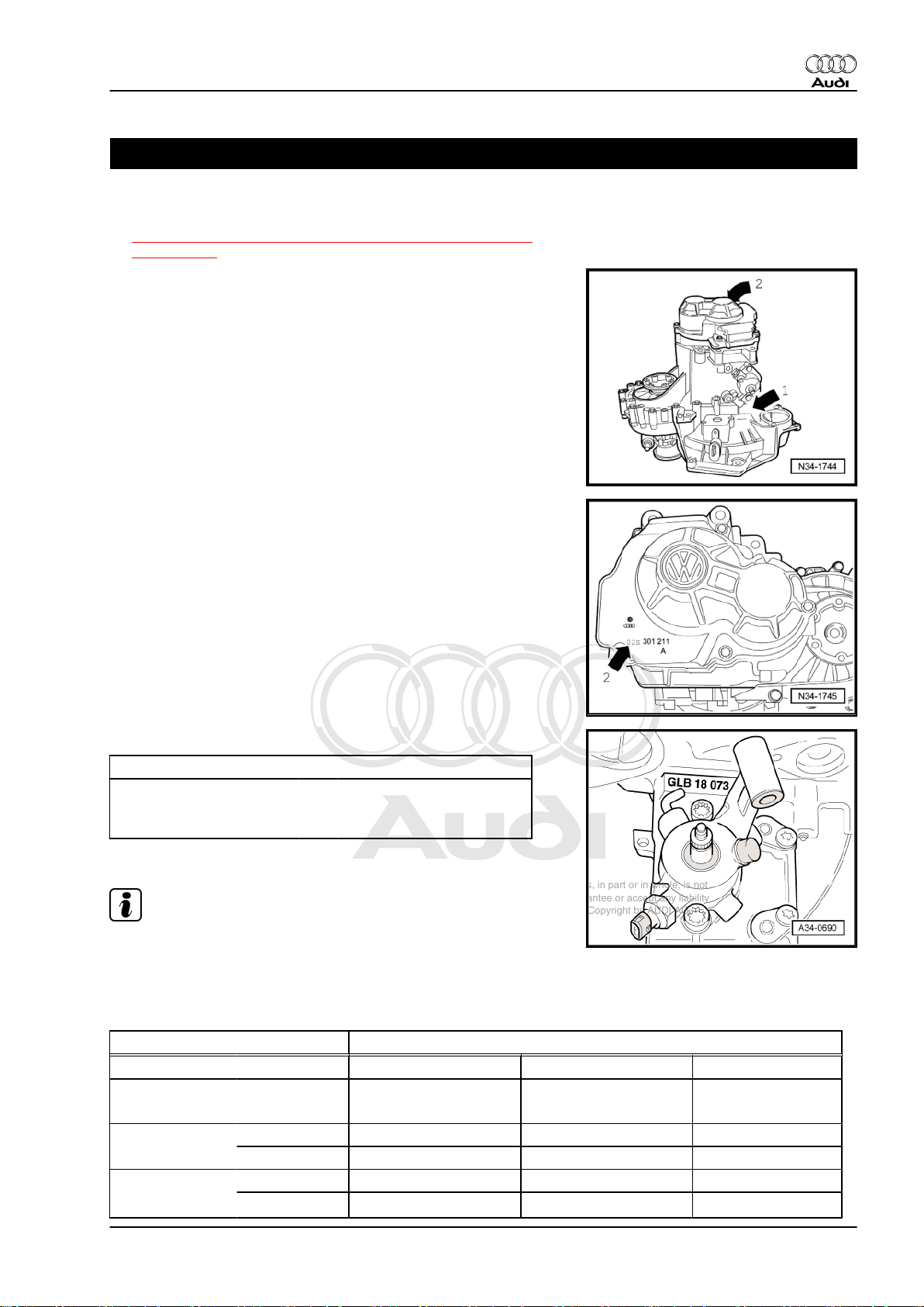
Location on gearbox
♦ Code letters and date of manufacture -arrow 1-
♦ Manual gearbox 02S -arrow 2-
Manual gearbox 02S -arrow 2-
Audi TT 2007 ➤
Code letters and date of manufacture of gearbox
Example: GLB 18 07 3
Additional data are production-related.
Note
I I I I
Code letters Day Month Year (2003) of
manufacture
The code letters for the gearbox are also given on the vehicle data
stickers.
1.1 Code letters, allocation, transmission ratios, capacities
Manual gearbox 6-speed 02S
to
JWX KVT
Code letters
Manufactured from 02.08 05.08
Allocation Model Audi TT 2007 ▸ Audi TT 2007 ▸
Ratio Final drive 62 : 17 = 3.647 62 : 17 = 3.647
Z2 : Z1 = i
Engine 1.8 ltr. - 118 kW TFSI 1.8 ltr. - 118 kW TFSI
1st gear 34 : 9 = 3.778 34 : 9 = 3.778
1. Gearbox identification 1
Page 6

Protected by copyright. Copying for private or commercial purposes, in part or in whole, is not
permitted unless authorised by AUDI AG. AUDI AG does not guarantee or accept any liability
with respect to the correctness of information in this document. Copyright by AUDI AG.
Audi TT 2007 ➤
6-speed manual gearbox 02S, front-wheel drive - Edition 05.2008
Manual gearbox 6-speed 02S
Overall ratio i
in top gear 2.644 2.644
ov.
2nd gear 33 : 16 = 2.063 33 : 16 = 2.063
3rd gear 32 : 22 = 1.455 32 : 22 = 1.455
4th gear 31 : 28 = 1.107 31 : 28 = 1.107
5th gear 28 : 32 = 0.875 28 : 32 = 0.875
6th gear 29 : 40 = 0.725 29 : 40 = 0.725
Reverse gear 36 : 20 x 18 : 9 = 3.600 36 : 20 x 18 : 9 = 3.600
Capacity 2.1 litres
Clutch actuation Hydraulic
The following data can be found in the ⇒ Electronic parts catalogue .
♦ Gear oil specification
♦ Allocation of drive shaft flanges
♦ Allocation of clutch type
2 Rep. Gr.00 - Technical data
Page 7
Protected by copyright. Copying for private or commercial purposes, in part or in whole, is not
permitted unless authorised by AUDI AG. AUDI AG does not guarantee or accept any liability
with respect to the correctness of information in this document. Copyright by AUDI AG.
6-speed manual gearbox 02S, front-wheel drive - Edition 05.2008
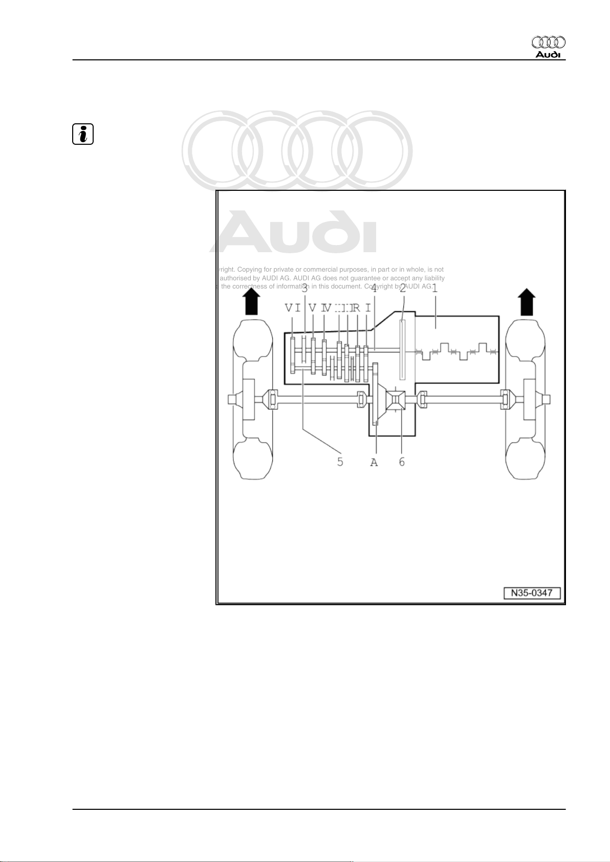
2 Transmission layout
Note
-Arrows- point in direction of travel.
1 - Engine
2 - Clutch
3 - Manual gearbox
4 - Input shaft (main shaft)
5 - Output shaft / pinion shaft
6 - Differential
I - 1st gear
II - 2nd gear
III - 3rd gear
IV - 4th gear
V - 5th gear
VI - 6th gear
R - Reverse gear
A - Final drive
Audi TT 2007 ➤
2. Transmission layout 3
Page 8

Protected by copyright. Copying for private or commercial purposes, in part or in whole, is not
permitted unless authorised by AUDI AG. AUDI AG does not guarantee or accept any liability
with respect to the correctness of information in this document. Copyright by AUDI AG.
Audi TT 2007 ➤
6-speed manual gearbox 02S, front-wheel drive - Edition 05.2008
3 Calculating ratio “i”
Example:
6th gear Final drive
Drive gear ZG1 = 38 ZA1 = 17
Driven gear ZG2 = 31 ZA2 = 62
i = Z2 : Z1
1)
iG = gear ratio = ZG2 : ZG1 = 31 : 38 = 0.816
iA = axle ratio = ZA2 : ZA1 = 62 : 17 = 3.647
iov = overall ratio
iov = iG x iA = 0.816 x 3.647 = 2.975
1) Z1 = No. of teeth on drive gear, Z2 = No. of teeth on driven gear
4 Rep. Gr.00 - Technical data
Page 9
Protected by copyright. Copying for private or commercial purposes, in part or in whole, is not
permitted unless authorised by AUDI AG. AUDI AG does not guarantee or accept any liability
with respect to the correctness of information in this document. Copyright by AUDI AG.
6-speed manual gearbox 02S, front-wheel drive - Edition 05.2008
4 General repair instructions
Proper tools and the maximum possible care and cleanliness are
essential for satisfactory gearbox repairs. The usual basic safety
precautions also naturally apply when carrying out repair work.
A number of generally applicable instructions for the various re‐
pair procedures - which were previously repeated at numerous
places in the Workshop Manual - are summarised here. They ap‐
ply to the work described in this Manual.
Special tools
♦ For a complete list of special tools used in this Workshop
Manual ⇒ Workshop equipment and special tools .
Gearbox
♦ Thoroughly clean all joints and connections and the surround‐
ing areas before dismantling.
♦ When installing, ensure that the dowel sleeves between the
engine and gearbox are correctly located.
♦ For allocation of bolts and other components, refer to ⇒ Elec‐
tronic parts catalogue .
♦ Clean contact surfaces when assembling mounting brackets
and waxed components. The contact surfaces must be free of
wax and grease.
♦ After installing a replacement gearbox, check oil level and top
up with gear oil as required ⇒ page 95 .
♦ Capacities and specifications ⇒ page 1
Sealants
♦ Thoroughly clean joint surfaces on gearbox housing etc. be‐
fore applying sealing paste.
♦ Apply sealing paste -AMV 188 200 03- evenly and not too
thick.
♦ Breather holes must remain free of sealing paste.
Oil seals, seals, O-rings and gaskets
♦ Always renew seals, O-rings and gaskets.
♦ After removing gaskets and seals, always inspect the contact
surface on the housing or shaft for burrs resulting from removal
or for other signs of damage.
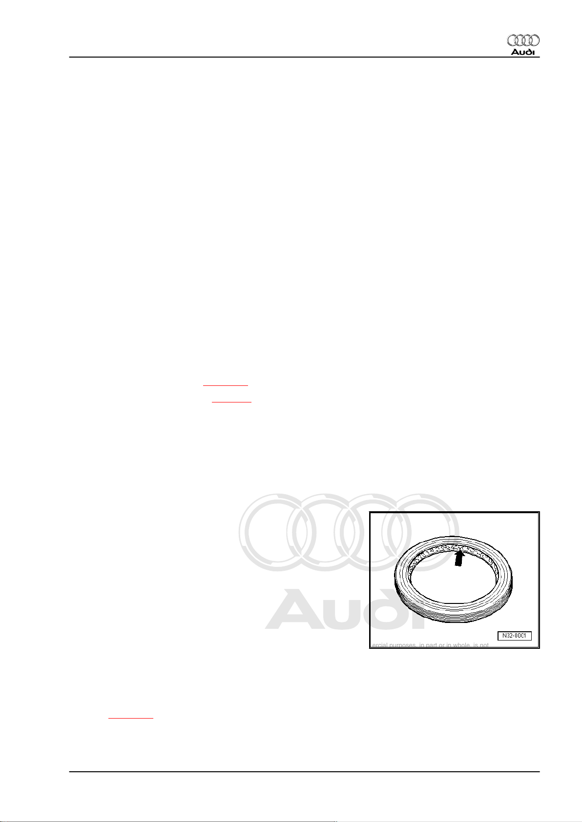
♦ Before installing oil seals, lightly oil the outer circumference of
the seal and fill the space between the sealing lips -arrowabout half full with grease -G 052 128 A1- .
♦ The open side of the oil seal should face the side containing
the fluid.
♦ When installing a new oil seal, position the seal in the housing
so that the sealing lip does not contact the shaft in the same
place as the old seal (make use of installation depth toleran‐
ces).
♦ Lightly lubricate O-rings with oil before installation to prevent
them being trapped during assembly.
♦ Check oil level after installing new gaskets, O-rings and oil
seals ⇒ page 95 .
Audi TT 2007 ➤
4. General repair instructions 5
Page 10
Protected by copyright. Copying for private or commercial purposes, in part or in whole, is not
permitted unless authorised by AUDI AG. AUDI AG does not guarantee or accept any liability
with respect to the correctness of information in this document. Copyright by AUDI AG.
Audi TT 2007 ➤
6-speed manual gearbox 02S, front-wheel drive - Edition 05.2008
Locking elements
♦ Do not over-stretch circlips.
♦ Always renew circlips which have been damaged or over-
stretched.
♦ Circlips must be properly seated in the base of the groove.
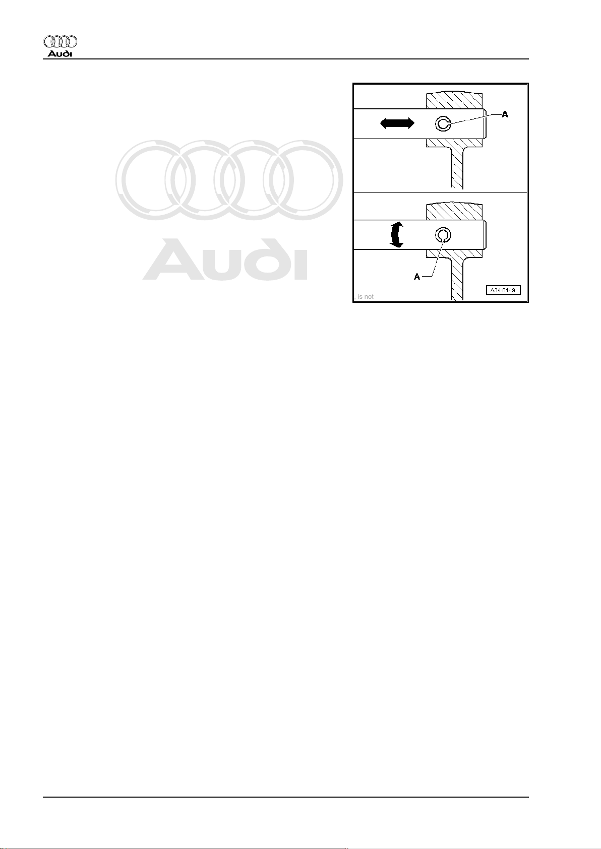
♦ Renew spring pins. Position: the slit -A- should be in line with
the line of force -arrow-.
Nuts, bolts
♦ Loosen the nuts and bolts in reverse sequence to the specified
tightening sequence.
♦ Nuts and bolts which secure covers and housings should be
loosened and tightened in diagonal sequence and in stages if
no tightening sequence is specified.
♦ Renew self-locking nuts and bolts.
♦ The tightening torques stated apply to non-oiled nuts and
bolts.
♦ Threaded holes which take self-locking bolts or bolts coated
with locking fluid must be cleaned (using a tap or similar). Oth‐
erwise there is a danger of the bolts shearing off the next time
they are removed.
♦ For all threaded connections, ensure that (where applicable)
the contact surfaces and the nuts and bolts are not coated with
wax until after assembly is completed.
Bearings
♦ Install new tapered roller bearings as supplied; do not lubricate
additionally with oil.
♦ Lubricate all bearings (except tapered roller bearings) with
gear oil before installing in gearbox.
♦ Use inductive heater -VAS 6414- to heat inner races of tapered
roller bearings to approx. 100°C before installing. Press home
onto stop when installing so there is no axial clearance.
♦ Do not interchange inner or outer races of bearings of the
same size.
♦ If required, renew the tapered roller bearings on one shaft to‐
gether and use new bearings from a single manufacturer.
♦ Install needle bearings so the lettering (side with thicker metal)
faces towards the installing tool.
Shims
♦ Use a micrometer to measure the shims at several points.
Tolerance variations make it possible to obtain the exact shim
thickness required.
♦ Check for burrs and damage. Install only shims which are in
perfect condition.
Synchro-rings
6 Rep. Gr.00 - Technical data
Page 11
Protected by copyright. Copying for private or commercial purposes, in part or in whole, is not
permitted unless authorised by AUDI AG. AUDI AG does not guarantee or accept any liability
with respect to the correctness of information in this document. Copyright by AUDI AG.
6-speed manual gearbox 02S, front-wheel drive - Edition 05.2008
♦ Do not interchange synchro-rings. When reusing always fit to
the same gear.
♦ Check for wear; renew if necessary.
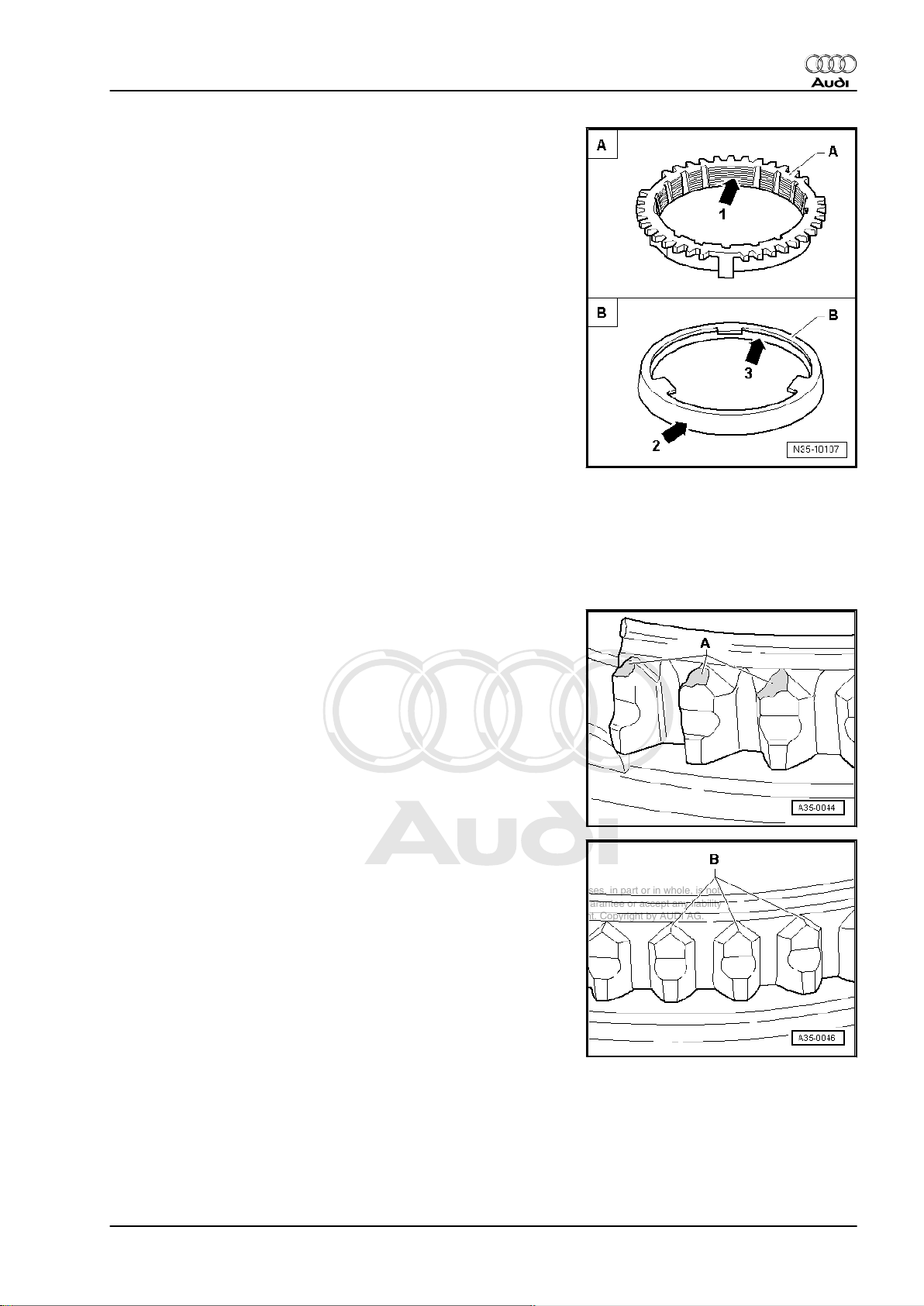
♦ Check the grooves -arrow 1- on synchro-ring -A- and on inner
ring for wear (flattened sections in grooves).
♦ Make sure that the coating of coated synchro-rings is not dam‐
aged.
♦ If an intermediate ring -B- is fitted, check the outer contact
surface -arrow 2- and inner contact surface -arrow 3- of the
intermediate ring for “scoring”, “visible traces of wear” and
“blue discolouration (caused by overheating)”.
♦ Check chamfer on selector gear for scoring and visible traces
of wear.
♦ Lubricate with gear oil before installing.
Gear wheels
♦ Clean before pressing on.
♦ Use inductive heater -VAS 6414- to heat to approx. 100°C be‐
fore installing. Press home onto stop when installing so there
is no axial clearance.
Selector gears and locking collars
♦ After installing, check 1st to 6th speed selector gears for min‐
imal axial play and freedom of movement.
Audi TT 2007 ➤
♦ Abnormal wear on synchro-ring or selector gear:
A - Worn ends of dog teeth on synchro-ring or selector gear.
♦ In comparison: intact synchro-ring or selector gear:
B - Intact ends of dog teeth on synchro-ring or selector gear.
4. General repair instructions 7
Page 12
Protected by copyright. Copying for private or commercial purposes, in part or in whole, is not
permitted unless authorised by AUDI AG. AUDI AG does not guarantee or accept any liability
with respect to the correctness of information in this document. Copyright by AUDI AG.
Audi TT 2007 ➤
6-speed manual gearbox 02S, front-wheel drive - Edition 05.2008
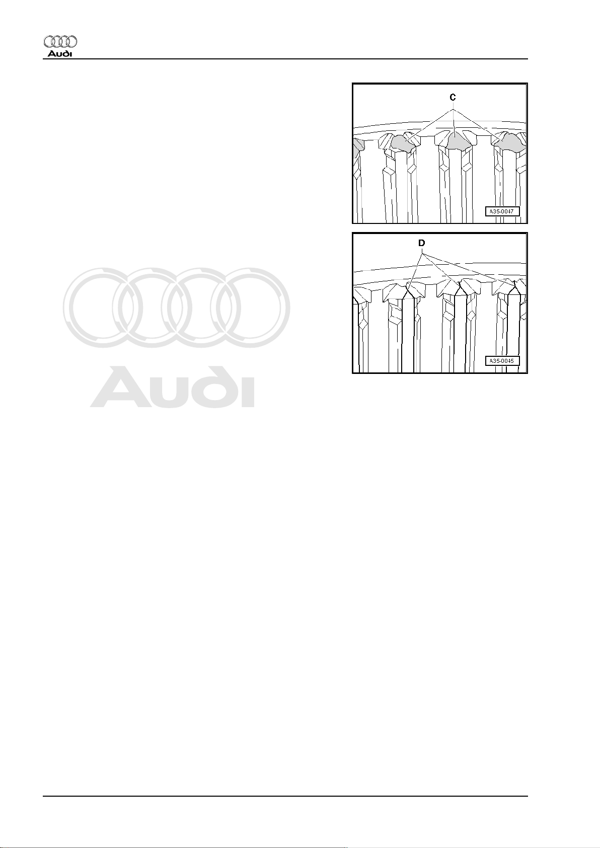
♦ Abnormal wear on locking collar:
C - Worn ends of internal splines on locking collar.
♦ In comparison: intact locking collar:
D - Intact ends of internal splines on locking collar.
Clutch actuation
♦ When removing gearbox, remove clutch slave cylinder without
disconnecting pipes.
♦ Do not depress the clutch pedal after removing the slave cyl‐
inder if the hydraulic pipe is still connected. Otherwise the
piston will be pressed out of the slave cylinder.
♦ Ensure that the pressure plate is kept straight: loosen and
tighten bolts in a diagonal sequence and in several gradual
stages.
♦ If the clutch has burnt out, thoroughly clean the bell housing,
flywheel and parts of the engine facing the gearbox in order to
prevent odours.
8 Rep. Gr.00 - Technical data
Page 13
Protected by copyright. Copying for private or commercial purposes, in part or in whole, is not
permitted unless authorised by AUDI AG. AUDI AG does not guarantee or accept any liability
with respect to the correctness of information in this document. Copyright by AUDI AG.
6-speed manual gearbox 02S, front-wheel drive - Edition 05.2008
30 – Clutch
1 Overview - clutch mechanism
Note
If you suspect that a clutch master cylinder or clutch slave cylinder
is defective, observe and perform the following prior to renewing.
♦ ⇒ “2 Notes on removing and installing clutch master cylinder
and slave cylinder”, page 10
♦ ⇒ “2.1 Function check for clutch master cylinder and slave
cylinder”, page 10
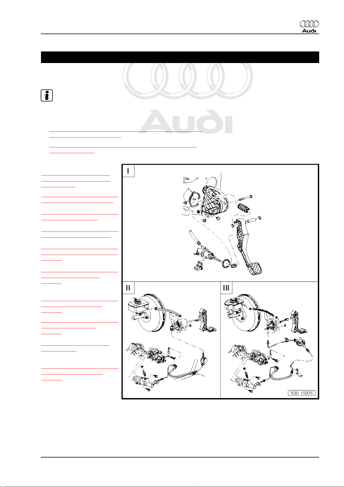
I -
⇒ “3 Exploded view - pedal
cluster, clutch master cylin‐
der”, page 12
⇒ “3.1 Removing and installing
over-centre spring”, page 13
Audi TT 2007 ➤
⇒ “3.2 Removing and installing
clutch pedal”, page 15
⇒ “3.3 Removing and installing
mounting bracket”, page 18
⇒ “3.4 Removing and installing
clutch position sender G476 ”,
page 20
⇒ “3.5 Removing and installing
clutch master cylinder”,
page 21
II -
⇒ “4 Exploded view - hydraulic
system (LHD vehicles)”,
page 23
⇒ “4.1 Removing and installing
clutch slave cylinder”,
page 25
⇒ “4.3 Bleeding clutch sys‐
tem”, page 29
III -
⇒ “5 Exploded view - hydraulic
system (RHD vehicles)”,
page 31
1. Overview - clutch mechanism 9
Page 14

Protected by copyright. Copying for private or commercial purposes, in part or in whole, is not
permitted unless authorised by AUDI AG. AUDI AG does not guarantee or accept any liability
with respect to the correctness of information in this document. Copyright by AUDI AG.
Audi TT 2007 ➤
6-speed manual gearbox 02S, front-wheel drive - Edition 05.2008
2 Notes on removing and installing
clutch master cylinder and slave cyl‐
inder
♦ Before renewing the clutch master cylinder or slave cylinder
on the assumption that it is defective you must first carry out
a function check
⇒ “2.1 Function check for clutch master cylinder and slave
cylinder”, page 10 .
♦ If slave cylinder is removed from gearbox with pipe/hose as‐
sembly still attached, make sure you do not press clutch pedal.
Otherwise, the piston will be pressed out of the slave cylinder
and be destroyed.
♦ After installing the slave cylinder, carefully press the clutch
pedal. If you feel an unusually strong point of resistance when
depressing the clutch pedal, you must not press it down fur‐
ther. The plunger of the slave cylinder is likely to have been
guided past the clutch release lever. The slave cylinder would
then be destroyed once pedal force exceeds approx. 300 N.
2.1 Function check for clutch master cylin‐
der and slave cylinder
Before you renew the clutch master cylinder or slave cylinder you
must - in the case of the following faults - first carry out the ap‐
propriate checks.
Noises when operating the clutch:
♦ First check the over-centre spring / clutch pedal switch for
noise.
♦ If you hear a noise, remove over-centre spring and repeat
check.
♦ Renew relevant component.
After releasing clutch pedal it still remains depressed / does not
return to its initial position.
♦ Check whether the clutch pedal returns all the way to its initial
position, thereby uncovering the vent opening in the master
cylinder.
♦ The vent opening is integrated in the clutch master cylinder. It
is not visible from the outside.
♦ The vent opening must be uncovered, otherwise the perma‐
nent self-bleeding function for the hydraulic clutch system will
no longer be effective.
♦ Make the customer aware that the driver must NOT rest his/
her foot on the clutch pedal for long periods of time. This could
impair the self-bleeding function of the clutch system as the
vent opening in the master cylinder can no longer function.
♦ The self-bleeding function of the clutch system can be im‐
paired if the footwell trim or floor mats get trapped, if the clutch
pedal switch jams or if the driver rests his foot on the clutch
pedal for long periods of time.
Check the complete hydraulic system for leaks.
♦ Check brake fluid level in brake fluid reservoir.
♦ Check clutch master cylinder and slave cylinder as well as the
pipe/hose assembly including connections for external leaks
(visual inspection).
10 Rep. Gr.30 - Clutch
Page 15

Protected by copyright. Copying for private or commercial purposes, in part or in whole, is not
permitted unless authorised by AUDI AG. AUDI AG does not guarantee or accept any liability
with respect to the correctness of information in this document. Copyright by AUDI AG.
6-speed manual gearbox 02S, front-wheel drive - Edition 05.2008
♦ If you identify any leaks you must renew the leaking compo‐
nent.
♦ Bleed clutch system ⇒ page 29 .
Pedal forces:
♦ approx. 140 N for complete service life of the clutch
High pedal force:
♦ Mechanically defective pressure plate/clutch plate
⇒ page 35 .
Clutch does not disengage or does not disengage fully:
♦ Air in hydraulic system: bleed clutch system ⇒ page 29 and
check hydraulic system for external and internal leaks.
♦ Clutch plate does not move smoothly on input shaft splines
(due to corrosion or dirt, etc.)
♦ Foreign body in clutch system
♦ Mechanically defective pressure plate/clutch plate
⇒ page 35 .
♦ Wrong components used or components forgotten when car‐
rying out repair work (e.g. intermediate plate or dowel
sleeves).
Audi TT 2007 ➤
2. Notes on removing and installing clutch master cylinder and slave cylinder 11
Page 16
Protected by copyright. Copying for private or commercial purposes, in part or in whole, is not
permitted unless authorised by AUDI AG. AUDI AG does not guarantee or accept any liability
with respect to the correctness of information in this document. Copyright by AUDI AG.
Audi TT 2007 ➤
6-speed manual gearbox 02S, front-wheel drive - Edition 05.2008
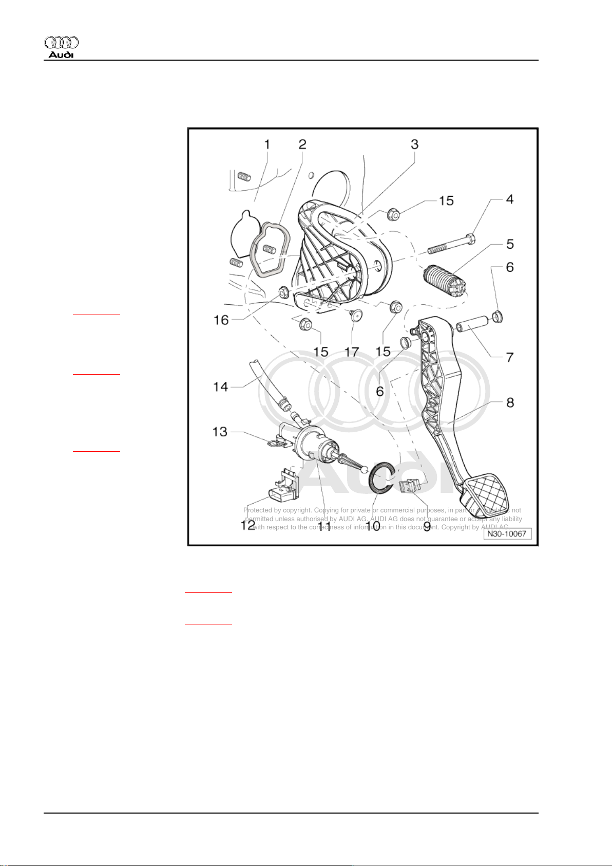
3 Exploded view - pedal cluster, clutch master cylinder
1 - Bulkhead
❑ With mounting for
mounting bracket
2 - Gasket
❑ Always renew
❑ Between mounting
bracket and bulkhead
❑ Self-adhesive
❑ Bond onto mounting
bracket
3 - Mounting bracket
❑ For clutch pedal
❑ Removing and installing
⇒ page 18
4 - Bolt
5 - Over-centre spring
❑ Removing and installing
⇒ page 13
6 - Bearing bush
7 - Pivot pin
8 - Clutch pedal
❑ Removing and installing
⇒ page 15
9 - Retaining clip
❑ For operating rod on
master cylinder
10 - Seal
❑ Always renew
❑ Between clutch master
cylinder and mounting
bracket
11 - Clutch master cylinder
❑ Removing and installing ⇒ page 21
12 - Clutch position sender -G476-
❑ Removing and installing ⇒ page 20
❑ Can be checked in “Guided Fault Finding”, using vehicle diagnostic, testing and information system -
VAS 5051- .
13 - Retaining clip
❑ To remove and install pipe/hose assembly, pull out clip as far as it will go
14 - Supply hose
❑ To brake fluid reservoir
15 - Nut
❑ 20 Nm
❑ 3x
❑ For securing mounting bracket to bulkhead
❑ Self-locking
❑ Always renew
12 Rep. Gr.30 - Clutch
Page 17
Protected by copyright. Copying for private or commercial purposes, in part or in whole, is not
permitted unless authorised by AUDI AG. AUDI AG does not guarantee or accept any liability
with respect to the correctness of information in this document. Copyright by AUDI AG.
6-speed manual gearbox 02S, front-wheel drive - Edition 05.2008
16 - Nut
❑ 25 Nm
❑ Self-locking
❑ Always renew
17 - Stop
❑ For clutch pedal
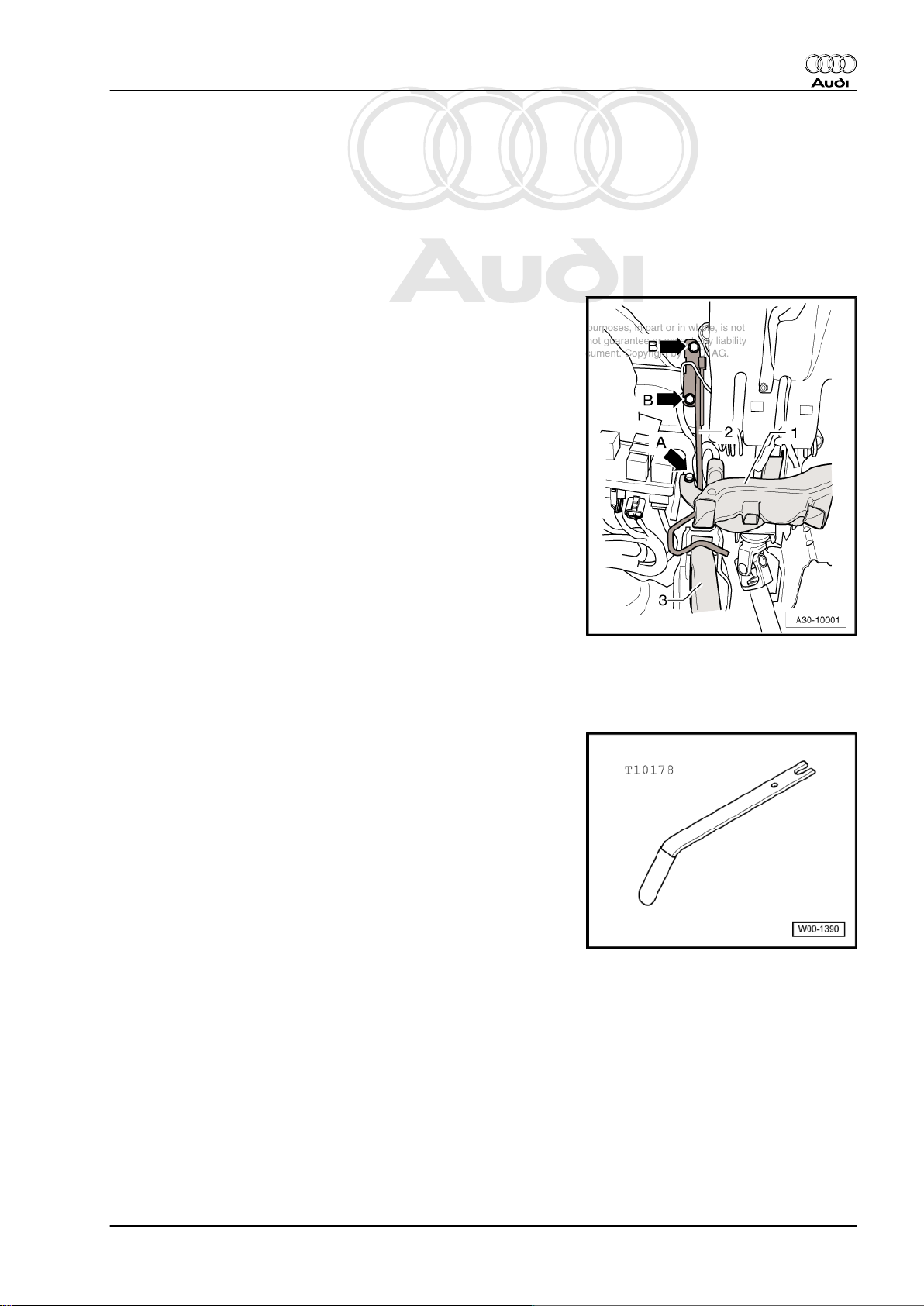
Crash bar - tightening torque
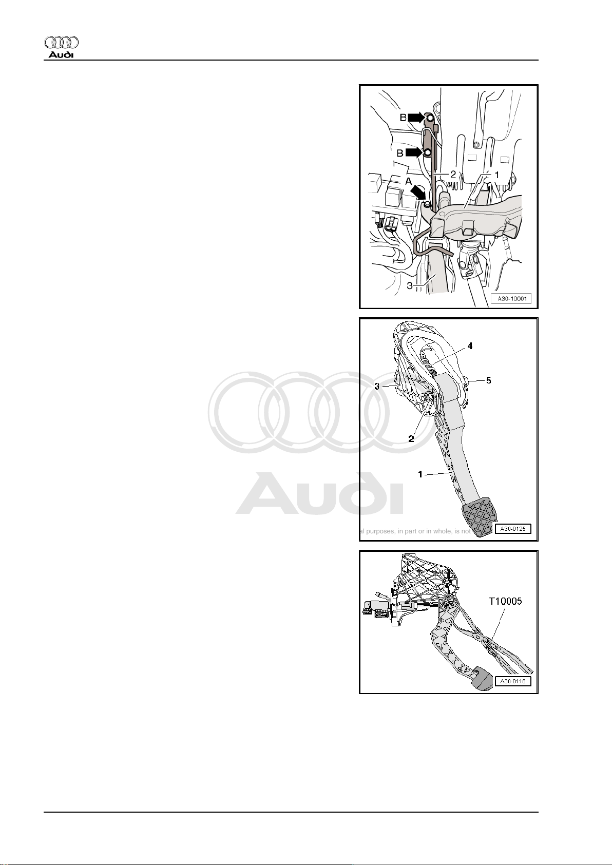
– Install crash bar -2- and tighten 1 or 2 bolts (depending on
version) -arrows B-.
• M6 10 Nm
• M8 20 Nm
Audi TT 2007 ➤
3.1 Removing and installing over-centre spring
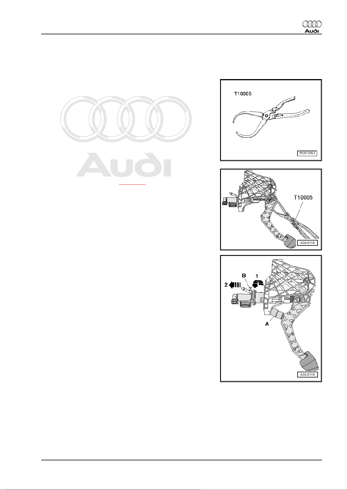
Special tools and workshop equipment required
♦ Lever -T10178-
3. Exploded view - pedal cluster, clutch master cylinder 13
Page 18
Protected by copyright. Copying for private or commercial purposes, in part or in whole, is not
permitted unless authorised by AUDI AG. AUDI AG does not guarantee or accept any liability
with respect to the correctness of information in this document. Copyright by AUDI AG.
Audi TT 2007 ➤
6-speed manual gearbox 02S, front-wheel drive - Edition 05.2008
Removing
• Clutch pedal mounting bracket fitted in vehicle
– Move driver's seat away from pedals.
– Remove storage compartment on driver's side ⇒ Rep. Gr.
68 .
– Unscrew bolt -arrow A- and remove footwell air outlet (front
left) -1-.
– Unclip wiring harness at rear of footwell air outlet -1- and move
clear to one side.
– Unbolt crash bar -2- (secured by one or two bolts -arrows B-,
depending on version).
– Unbolt clutch pedal -1- from mounting bracket -3-. To do this,
remove nut -2- and pull out bolt -5-.
Note
The clutch pedal does not have to be detached from the operating
rod on the clutch master cylinder.
– Pivot clutch pedal down slightly and and take over-centre
spring -4- out of mounting bracket.
Installing
• Tightening torques ⇒ page 12
Installation is carried out in reverse sequence; note the following:
Note
♦
Renew self-locking nut.
♦
Lubricate all bearings and contact surfaces with grease -G 000
450 02- .
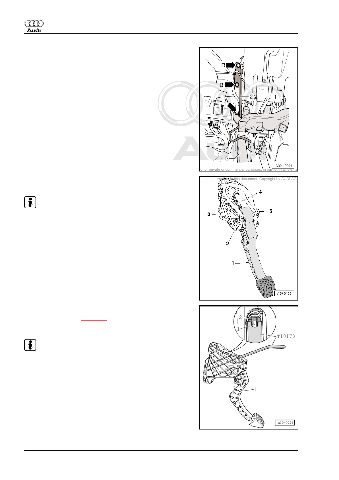
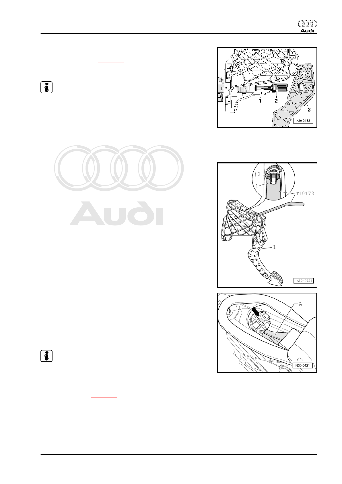
– Fit over-centre spring -2- into mounting bracket from above
while holding end of spring in correct position with assembly
tool -T10178- .
14 Rep. Gr.30 - Clutch
Page 19
Protected by copyright. Copying for private or commercial purposes, in part or in whole, is not
permitted unless authorised by AUDI AG. AUDI AG does not guarantee or accept any liability
with respect to the correctness of information in this document. Copyright by AUDI AG.
6-speed manual gearbox 02S, front-wheel drive - Edition 05.2008
• Socket -arrow- of over-centre spring must be in vertical posi‐
tion.
– Fit actuator on clutch pedal -A- into corresponding socket in
over-centre spring -arrow-.
– Press clutch pedal slightly, push bolt through and tighten self-
locking nut.
– Install crash bar ⇒ page 13 .
– Install front footwell vent (left-side) ⇒ Rep. Gr. 80 .
– Install storage compartment on driver's side ⇒ Rep. Gr. 68 .
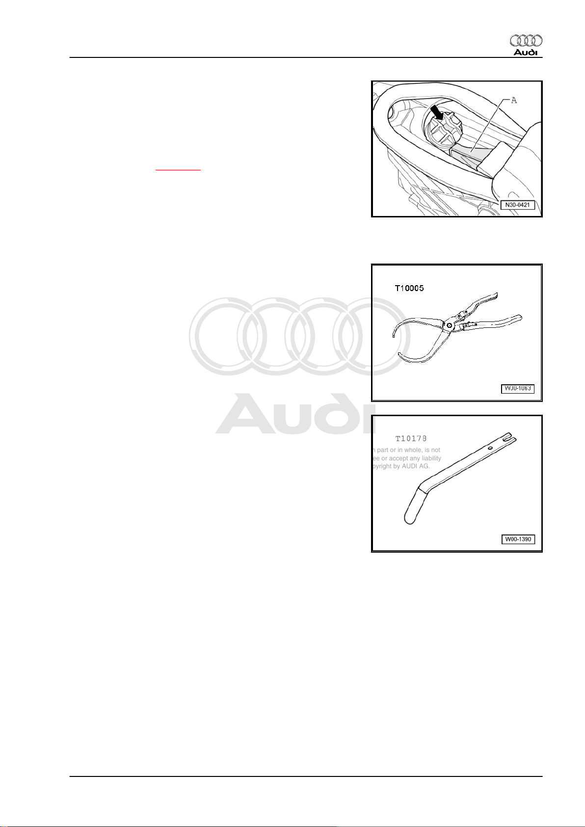
3.2 Removing and installing clutch pedal
Special tools and workshop equipment required
♦ Pliers -T10005-
Audi TT 2007 ➤
♦ Lever -T10178-
3. Exploded view - pedal cluster, clutch master cylinder 15
Page 20
Protected by copyright. Copying for private or commercial purposes, in part or in whole, is not
permitted unless authorised by AUDI AG. AUDI AG does not guarantee or accept any liability
with respect to the correctness of information in this document. Copyright by AUDI AG.
Audi TT 2007 ➤
6-speed manual gearbox 02S, front-wheel drive - Edition 05.2008
Removing
• Clutch pedal mounting bracket fitted in vehicle
– Move driver's seat away from pedals.
– Remove storage compartment on driver's side ⇒ Rep. Gr.
68 .
– Unscrew bolt -arrow A- and remove footwell air outlet (front
left) -1-.
– Unclip wiring harness at rear of footwell air outlet -1- and move
clear to one side.
– Unbolt crash bar -2- (secured by one or two bolts -arrows B-,
depending on version).
– Unbolt clutch pedal -1- from mounting bracket -3-. To do this,
remove nut -2- and pull out bolt -5-.
– Pivot clutch pedal forward slightly and and take over-centre
spring -4- out of mounting bracket.
– Release retaining clip for operating rod on clutch master cyl‐
inder using pliers -T10005- .
– Remove clutch pedal.
16 Rep. Gr.30 - Clutch
Page 21
Protected by copyright. Copying for private or commercial purposes, in part or in whole, is not
permitted unless authorised by AUDI AG. AUDI AG does not guarantee or accept any liability
with respect to the correctness of information in this document. Copyright by AUDI AG.
6-speed manual gearbox 02S, front-wheel drive - Edition 05.2008
Installing
• Tightening torques ⇒ page 12
Installation is carried out in reverse sequence; note the following:
Note
♦
Renew self-locking nut.
♦
Lubricate all bearings and contact surfaces with grease -G 000
450 02- .
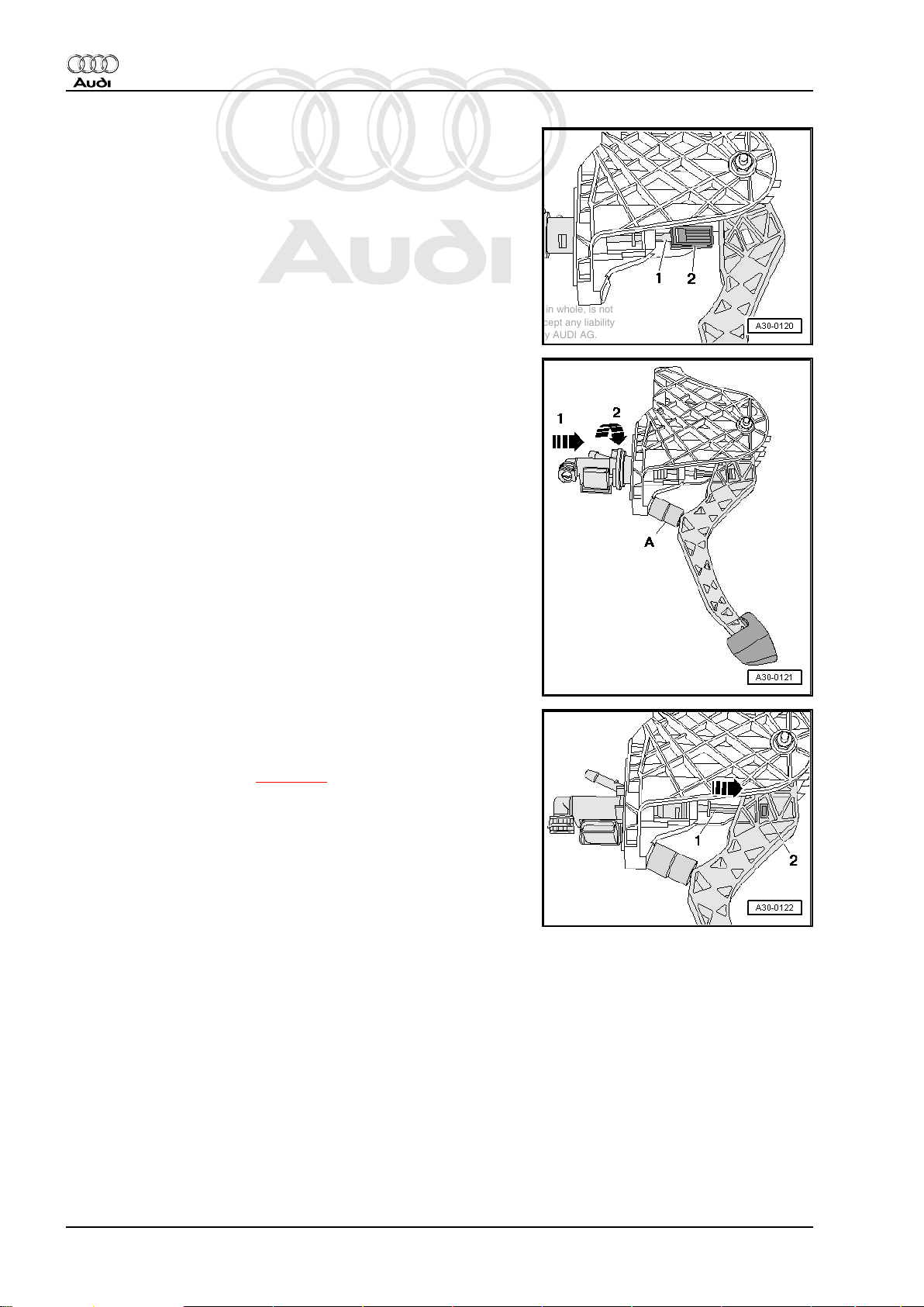
– Fit retaining clip -2- on operating rod -1- for clutch master cyl‐
inder.
– Press retaining clip into mounting on clutch pedal so that it
snaps into place audibly.
– Fit over-centre spring -2- into mounting bracket from above
while holding end of spring in correct position with assembly
tool -T10178- .
Audi TT 2007 ➤
• Socket -arrow- of over-centre spring must be in vertical posi‐
tion.
– Fit actuator on clutch pedal -A- into corresponding socket in
over-centre spring -arrow-.
– Press top of clutch pedal forwards against spring pressure of
over-centre spring, push through bolt and tighten self-locking
nut.
Note
It is easier to press the pedal against the spring if you pull back
the bottom of the pedal carefully as you bring the top of the pedal
into position.
– Install crash bar ⇒ page 13 .
– Install front footwell vent (left-side) ⇒ Rep. Gr. 80 .
– Install storage compartment on driver's side ⇒ Rep. Gr. 68 .
3. Exploded view - pedal cluster, clutch master cylinder 17
Page 22
Protected by copyright. Copying for private or commercial purposes, in part or in whole, is not
permitted unless authorised by AUDI AG. AUDI AG does not guarantee or accept any liability
with respect to the correctness of information in this document. Copyright by AUDI AG.
Audi TT 2007 ➤
6-speed manual gearbox 02S, front-wheel drive - Edition 05.2008
3.3 Removing and installing mounting bracket
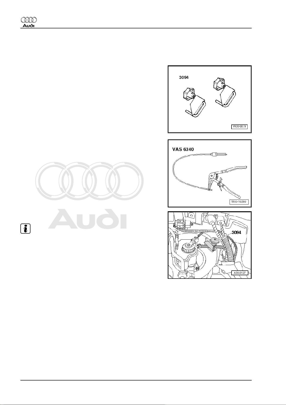
Special tools and workshop equipment required
♦ Hose clamps, up to Ø 25 mm -3094-
Hose clip pliers -VAS 6340-
Removing
Note
In the following steps make sure that no brake fluid escapes onto
the longitudinal member or onto the gearbox below. If this does
happen, clean the affected area thoroughly.
– Using hose clamp -3094- , clamp off supply hose to master
cylinder.
18 Rep. Gr.30 - Clutch
Page 23
Protected by copyright. Copying for private or commercial purposes, in part or in whole, is not
permitted unless authorised by AUDI AG. AUDI AG does not guarantee or accept any liability
with respect to the correctness of information in this document. Copyright by AUDI AG.
6-speed manual gearbox 02S, front-wheel drive - Edition 05.2008
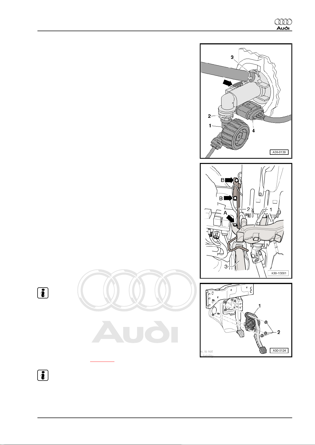
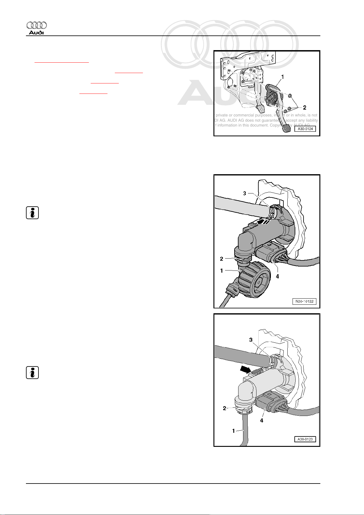
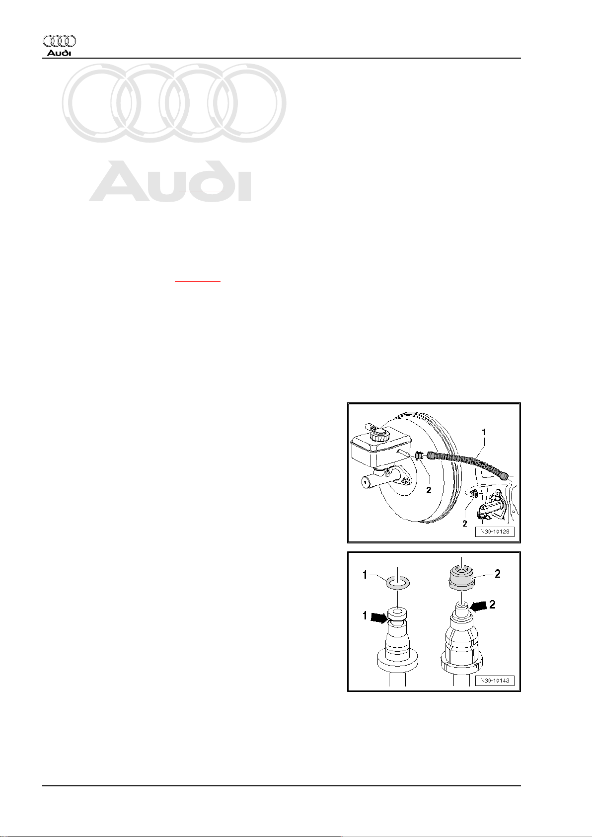
– Disconnect supply hose at clutch master cylinder (if necessa‐
ry, release spring-type clip -3- using hose clip pliers -VAS
6340- ).
– Release retaining clip -2- with a screwdriver and disconnect
pipe/hose assembly -1- from master cylinder.
– Unclip and detach clutch pedal position sender -G476- from
master cylinder -arrow-. Electrical connector -4- can remain
connected.
– Move driver's seat to rear as far as possible and move steering
wheel into uppermost position.
– Remove storage compartment on driver's side ⇒ Rep. Gr.
68 .
– Unscrew bolt -arrow A- and remove footwell air outlet (front
left) -1-.
– Unclip wiring harness at rear of footwell air outlet -1- and move
clear to one side.
– Unbolt crash bar -2- (secured by one or two bolts -arrows B-,
depending on version).
Audi TT 2007 ➤
Note
When performing work in the footwell, put cloths on the carpet to
protect it from possible brake fluid spills.
– Remove nuts -2-.
– Take out mounting bracket -1-.
Installing
Installation is carried out in reverse sequence; note the following:
• Tightening torques ⇒ page 12
Note
♦
Renew self-locking nuts.
♦
Secure all hose connections with the correct hose clips (as
original equipment); refer to ⇒ Parts catalogue .
3. Exploded view - pedal cluster, clutch master cylinder 19
Page 24
Protected by copyright. Copying for private or commercial purposes, in part or in whole, is not
permitted unless authorised by AUDI AG. AUDI AG does not guarantee or accept any liability
with respect to the correctness of information in this document. Copyright by AUDI AG.
Audi TT 2007 ➤
6-speed manual gearbox 02S, front-wheel drive - Edition 05.2008
– Fit mounting bracket -1- and tighten nuts -2-. Tightening torque
⇒ Item 15 (page 12) .
– Connect pipe/hose assembly ⇒ page 25 .
– Bleed clutch system ⇒ page 29 .
– Install crash bar ⇒ page 13 .
– Install front footwell vent (left-side) ⇒ Rep. Gr. 80 .
– Install storage compartment on driver's side ⇒ Rep. Gr. 68 .
3.4 Removing and installing clutch position sender -G476-
Removing
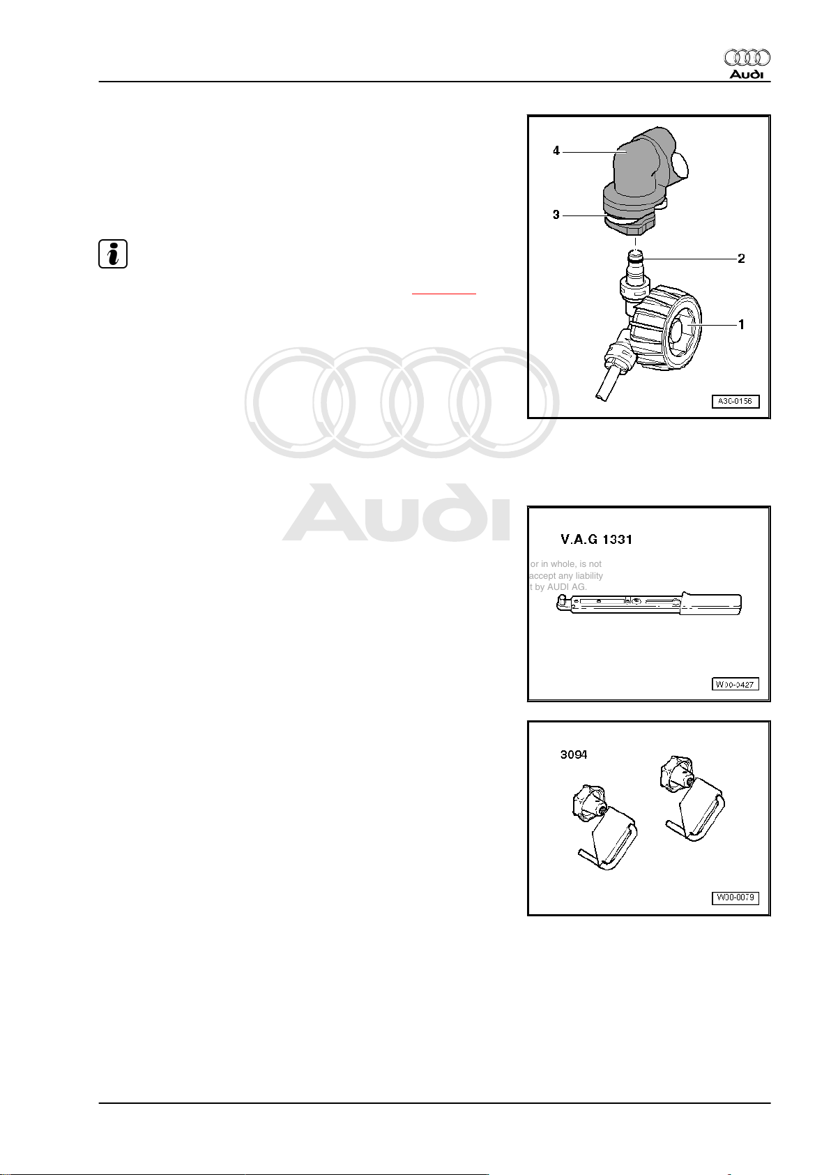
– Unplug electrical connector -4-.
– Unclip clutch position sender -G476- at clutch master cylinder
in direction of -arrow- and remove.
Note
Items -1 ... 3- can be disregarded.
Installing
Perform installation in reverse sequence of removal.
– Fit clutch position sender -G476- at clutch master cylinder and
engage -arrow-.
– Attach electrical connector -4-.
Note
Items -1 ... 3- can be disregarded.
20 Rep. Gr.30 - Clutch
Page 25
Protected by copyright. Copying for private or commercial purposes, in part or in whole, is not
permitted unless authorised by AUDI AG. AUDI AG does not guarantee or accept any liability
with respect to the correctness of information in this document. Copyright by AUDI AG.
6-speed manual gearbox 02S, front-wheel drive - Edition 05.2008
3.5 Removing and installing clutch master cylinder
Special tools and workshop equipment required
♦ Pliers -T10005-
Removing
– Remove mounting bracket ⇒ page 18 .
– Release retaining clip for operating rod on clutch pedal using
pliers -T10005- .
Audi TT 2007 ➤
– Insert a spacer -A- between clutch pedal and stop, and press
clutch pedal forward.
•
Length of spacer = approx. 40 mm (e.g. 1/2” socket)
– Release retaining clip -B- and pull clutch master cylinder out
of mounting bracket -arrows 1 and 2-.
3. Exploded view - pedal cluster, clutch master cylinder 21
Page 26
Protected by copyright. Copying for private or commercial purposes, in part or in whole, is not
permitted unless authorised by AUDI AG. AUDI AG does not guarantee or accept any liability
with respect to the correctness of information in this document. Copyright by AUDI AG.
Audi TT 2007 ➤
6-speed manual gearbox 02S, front-wheel drive - Edition 05.2008
Installing
• Clutch pedal in “released” position.
– Install retaining clip -2- on operating rod -1- for clutch master
cylinder.
– Insert a spacer -A- between clutch pedal and stop, and press
clutch pedal forward.
♦
Length of spacer = approx. 40 mm (e.g. 1/2” socket)
– Lock clutch master cylinder on mounting bracket
-arrows 1 and 2-.
– Press operating rod -1- for clutch master cylinder in direction
of -arrow- so that retaining clip -2- snaps into place in clutch
pedal.
– Install mounting bracket ⇒ page 18 .
22 Rep. Gr.30 - Clutch
Page 27
Protected by copyright. Copying for private or commercial purposes, in part or in whole, is not
permitted unless authorised by AUDI AG. AUDI AG does not guarantee or accept any liability
with respect to the correctness of information in this document. Copyright by AUDI AG.
6-speed manual gearbox 02S, front-wheel drive - Edition 05.2008
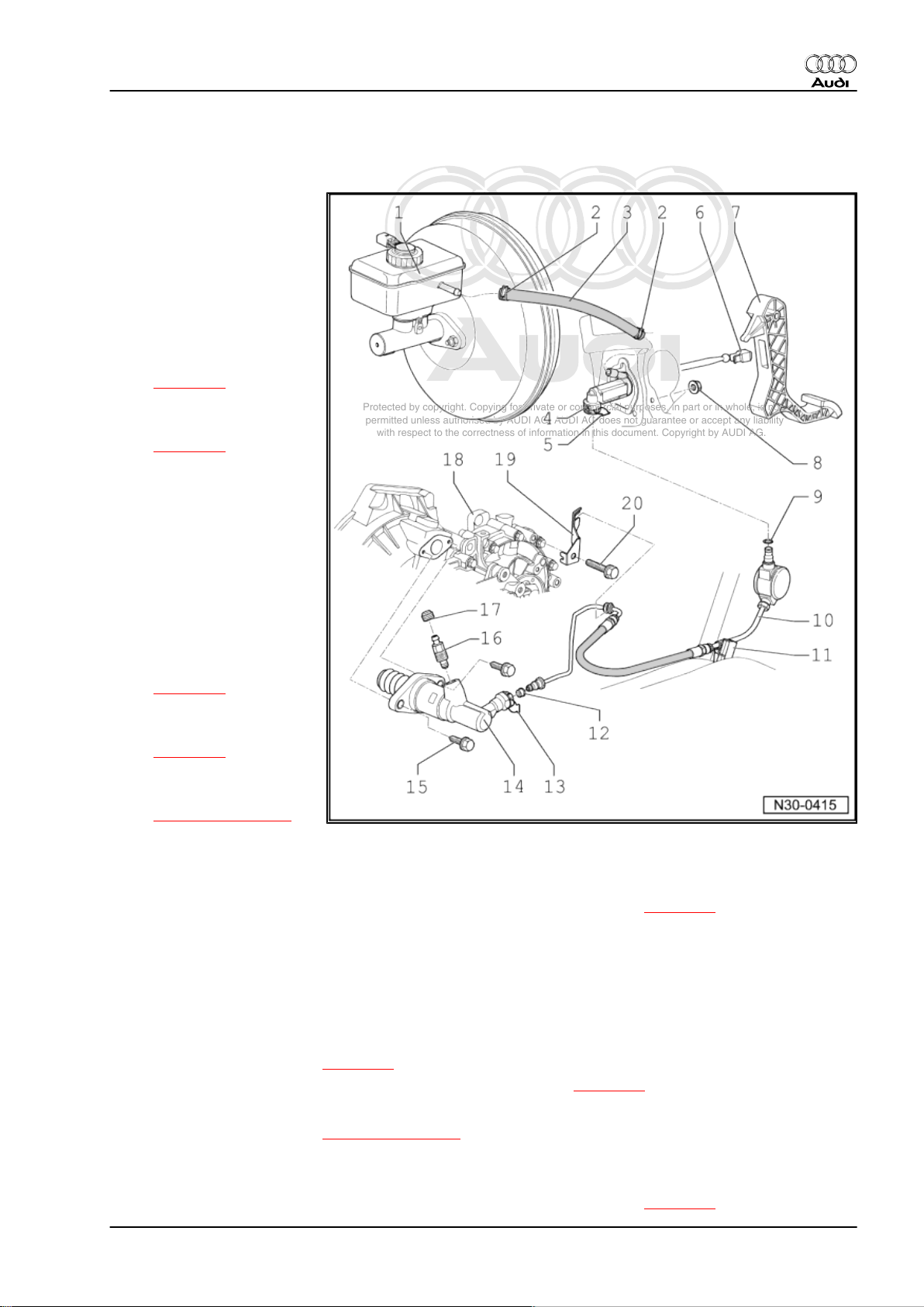
4 Exploded view - hydraulic system (LHD vehicles)
1 - Brake fluid reservoir
2 - Hose clip (spring-type clip)
❑ Not fitted in all vehicles
3 - Supply hose
❑ Made of rubber or plas‐
tic, depending on ver‐
sion
❑ Plastic supply hose with
additional seals
⇒ page 24
4 - Clutch master cylinder
❑ Removing and installing
⇒ page 21
5 - Clip
❑ To remove and install
pipe/hose assembly,
pull out clip as far as it
will go
6 - Retaining clip
❑ For operating rod for
clutch master cylinder
❑ To remove and install
retaining clip first detach
clutch master cylinder
from clutch pedal
⇒ page 15
7 - Clutch pedal
❑ Removing and installing
⇒ page 15
8 - Nut
❑ Tightening torque
⇒ Item 15 (page 12)
❑ Secures mounting bracket to body
❑ Always renew
9 - Seal or O-ring
❑ Whether a seal or an O-ring is used depends on the type of connection ⇒ page 24
❑ For correct version, refer to ⇒ Electronic parts catalogue
❑ Renew damaged O-rings
❑ Push onto pipe connection
❑ Lubricate O-rings with brake fluid
10 - Pipe/hose assembly
❑ With frequency modulator
❑ Removing and installing ⇒ page 27
❑ Disconnecting from clutch master cylinder and slave cylinder ⇒ page 25
11 - Bracket
❑ For pipe/hose assembly ⇒ Item 10 (page 23)
❑ Secured on body
12 - Seal or O-ring
❑ Whether a seal or an O-ring is used depends on the type of connection ⇒ page 24
Audi TT 2007 ➤
4. Exploded view - hydraulic system (LHD vehicles) 23
Page 28
Protected by copyright. Copying for private or commercial purposes, in part or in whole, is not
permitted unless authorised by AUDI AG. AUDI AG does not guarantee or accept any liability
with respect to the correctness of information in this document. Copyright by AUDI AG.
Audi TT 2007 ➤
6-speed manual gearbox 02S, front-wheel drive - Edition 05.2008
❑ For correct version, refer to ⇒ Electronic parts catalogue
❑ Renew damaged O-rings
❑ Push onto pipe connection
❑ Lubricate O-rings with brake fluid
13 - Clip
❑ To remove and install pipe/hose assembly, pull out clip as far as it will go
14 - Clutch slave cylinder
❑ Removing and installing ⇒ page 25
15 - Bolt
❑ 20 Nm
❑ 2x
16 - Bleeder valve
❑ 6 Nm
❑ Bleeding clutch system ⇒ page 29
17 - Dust cap
18 - Gearbox
19 - Bracket
❑ For pipe/hose assembly
20 - Bolt
❑ 20 Nm
Vehicles with plastic supply hose -1-
• Seals -2- must be fitted in supply hose.
Seal/O-ring for pipe/hose assembly
1 - O-ring
♦ Connection with annular groove -arrow 1-
♦ Check O-ring for damage and renew if necessary
2 - Seal
♦ Connection with shoulder -arrow 2-
♦ Position seal -2- onto connection -arrow 2- before fitting
24 Rep. Gr.30 - Clutch
Page 29
Protected by copyright. Copying for private or commercial purposes, in part or in whole, is not
permitted unless authorised by AUDI AG. AUDI AG does not guarantee or accept any liability
with respect to the correctness of information in this document. Copyright by AUDI AG.
6-speed manual gearbox 02S, front-wheel drive - Edition 05.2008
Disconnecting/connecting pipe/hose assembly from/to clutch
master cylinder or clutch slave cylinder
– To remove, release clip -3- with a screwdriver and disconnect
pipe/hose assembly -1- from clutch master cylinder or clutch
slave cylinder -4-.
Installing
Note
Observe distinction between seals -2- and O-rings ⇒ page 24
– Press pipe/hose assembly -1- into connection on clutch slave
cylinder or clutch master cylinder -4- until clip -3- snaps into
place.
– Pull on pipe to check it is secure.
4.1 Removing and installing clutch slave cylinder
Audi TT 2007 ➤
Special tools and workshop equipment required
♦ -V.A.G 1331- Torque wrench
♦ Hose clamps, up to Ø 25 mm -3094-
4. Exploded view - hydraulic system (LHD vehicles) 25
Page 30
Protected by copyright. Copying for private or commercial purposes, in part or in whole, is not
permitted unless authorised by AUDI AG. AUDI AG does not guarantee or accept any liability
with respect to the correctness of information in this document. Copyright by AUDI AG.
Audi TT 2007 ➤
6-speed manual gearbox 02S, front-wheel drive - Edition 05.2008
Removing
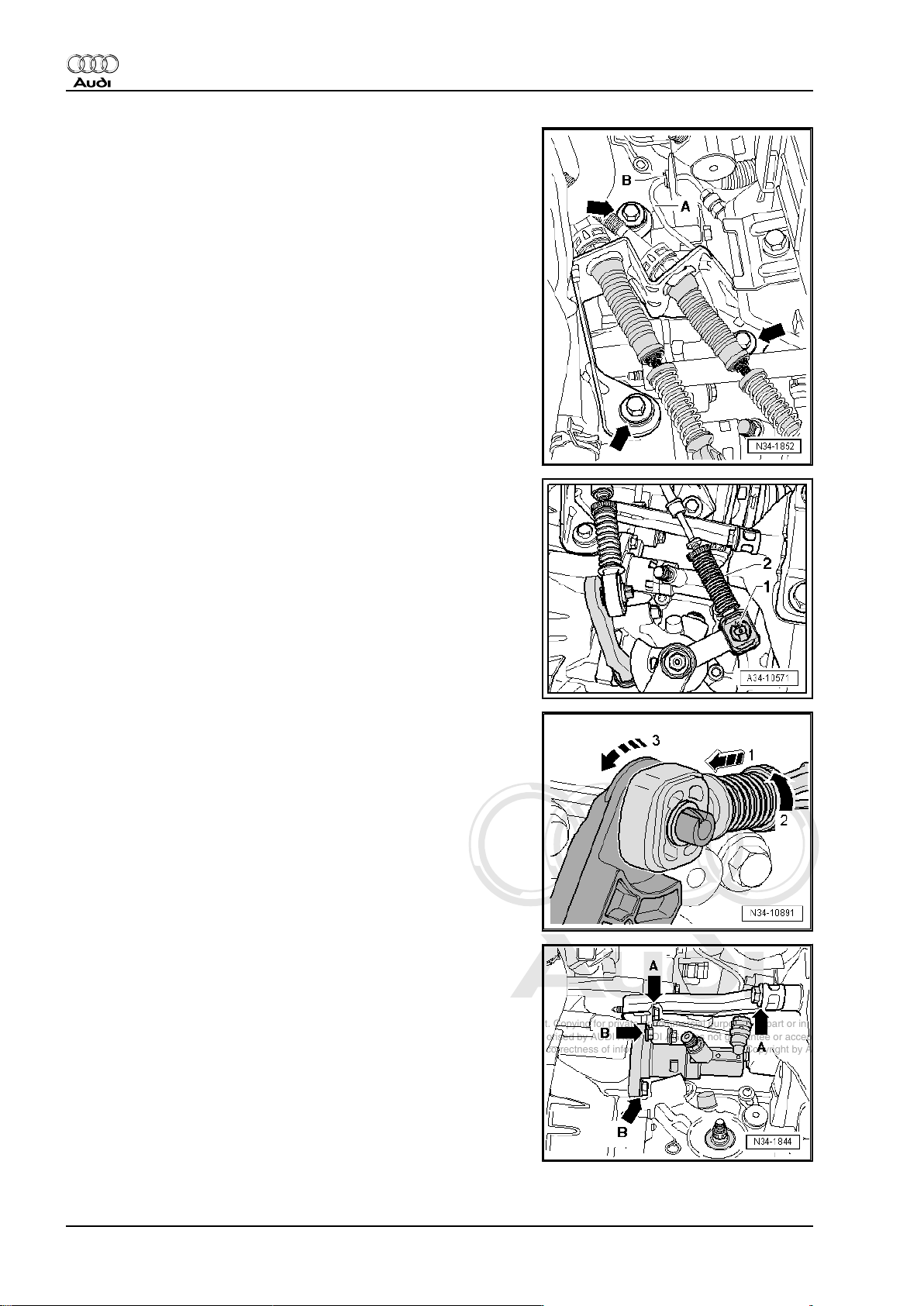
– Detach cable support bracket from gearbox -arrows-.
– Remove securing clip -1-.
– Pull gear selector cable -2- off pin.
– Pull locking mechanism forwards in direction of -arrow 1- onto
stop and then turn to left in direction of -arrow 2- to lock.
– Press relay lever forwards (in direction of -arrow 3-) and pull
out gate selector cable.
– Tie back gear selector cable and gate selector cable.
– Detach gearbox support -arrows A-.
– Remove clutch slave cylinder -arrows B-.
26 Rep. Gr.30 - Clutch
Page 31

Protected by copyright. Copying for private or commercial purposes, in part or in whole, is not
permitted unless authorised by AUDI AG. AUDI AG does not guarantee or accept any liability
with respect to the correctness of information in this document. Copyright by AUDI AG.
6-speed manual gearbox 02S, front-wheel drive - Edition 05.2008
Note
Make sure that no brake fluid escapes onto the gearbox. If this
does happen, clean the affected area thoroughly.
– Place a lint-free cloth under the clutch slave cylinder.
– Using hose clamps, up to Ø 25 mm -3094- , clamp off pipe/
hose assembly to clutch master cylinder.
– Pull out clip -1- as far as it will go, move pipe/hose assembly
-2- clear at bracket and disconnect from clutch slave cylinder.
Caution
Do not operate clutch pedal after disconnecting pipe/hose as‐
sembly.
Installing
Installation is carried out in the reverse order; note the following:
– Connect pipe/hose assembly to clutch slave cylinder
⇒ page 25 .
– Lubricate end of plunger with MoS2 grease.
Audi TT 2007 ➤
– Fit clutch slave cylinder and tighten bolts -1- and -2-. Tighten‐
ing torque ⇒ Item 15 (page 24) .
– Clip pipe/hose assembly into bracket -arrow-.
– Remove hose clamp 3094.
– Fit gearbox support and tighten bolts -arrows-. Tightening tor‐
ques ⇒ Item 1 (page 90)
– Bleed clutch system ⇒ page 29 .
– Assemble selector mechanism ⇒ page 62 .
– Adjust selector mechanism ⇒ page 68 .
4.2 Removing and installing pipe/hose as‐
sembly
Special tools and workshop equipment required
4. Exploded view - hydraulic system (LHD vehicles) 27
Page 32

Protected by copyright. Copying for private or commercial purposes, in part or in whole, is not
permitted unless authorised by AUDI AG. AUDI AG does not guarantee or accept any liability
with respect to the correctness of information in this document. Copyright by AUDI AG.
Audi TT 2007 ➤
6-speed manual gearbox 02S, front-wheel drive - Edition 05.2008
♦ Hose clamps, up to Ø 25 mm -3094-
Removing
– Remove air cleaner housing completely ⇒ Rep. Gr. 24 .
– Remove bolts -arrows- and detach bracket for air cleaner
housing.
Note
♦
In the following steps make sure that no brake fluid escapes
onto the longitudinal member or onto the gearbox below. If this
does happen, clean the affected area thoroughly.
♦
Place a cloth underneath to catch escaping brake fluid.
– Use hose clamp -3094- to clamp off supply hose to clutch
master cylinder.
28 Rep. Gr.30 - Clutch
Page 33

Protected by copyright. Copying for private or commercial purposes, in part or in whole, is not
permitted unless authorised by AUDI AG. AUDI AG does not guarantee or accept any liability
with respect to the correctness of information in this document. Copyright by AUDI AG.
6-speed manual gearbox 02S, front-wheel drive - Edition 05.2008
– Release clip -3- with a screwdriver and disconnect pipe/hose
assembly -1- from clutch master cylinder and clutch slave cyl‐
inder.
– Detach pipe/hose assembly -1- from bracket and remove.
Installing
Installation is carried out in reverse sequence; note the following:
Note
Observe distinction between seals -2- and O-rings ⇒ page 24
– Press pipe/hose assembly -1- into connection on clutch slave
cylinder and master cylinder -4- so that clip -3- snaps into
place.
– Pull on pipe to check it is secure.
– Clip pipe/hose assembly into bracket -arrow-.
– Remove hose clamp 3094.
– Bleed clutch system ⇒ page 29 .
– Install complete air cleaner housing ⇒ Rep. Gr. 24 .
Audi TT 2007 ➤
4.3 Bleeding clutch system
Special tools and workshop equipment required
♦ -VAS 5234- Brake filling and bleeding equipment
Note
♦
The clutch system must be bled after performing work on the
hydraulic clutch mechanism.
♦
In the following steps make sure that no brake fluid escapes
onto the longitudinal member or onto the gearbox below.
♦
Prefilling the system is not necessary.
♦
Brake fluid specification ⇒ Rep. Gr. 47 .
4. Exploded view - hydraulic system (LHD vehicles) 29
Page 34

Protected by copyright. Copying for private or commercial purposes, in part or in whole, is not
permitted unless authorised by AUDI AG. AUDI AG does not guarantee or accept any liability
with respect to the correctness of information in this document. Copyright by AUDI AG.
Audi TT 2007 ➤
6-speed manual gearbox 02S, front-wheel drive - Edition 05.2008
– Pull clutch pedal back to its normal rest position.
– Connect brake filling and bleeding equipment -VAS 5234- or
-V.A.G 1869- .
– To bleed system, use bleed hose -V.A.G 1238/B- 3 - 670 mm
long, if necessary.
– Then connect bleeder hose to collector bottle of brake bleed‐
ing unit.
– Connect bleed hose to bleeder -arrow-.
– Now switch on bleeding equipment.
♦ Operating pressure 2.0 bar
– Open bleeder valve.
–
Bleed off about 100 cm3 of brake fluid.
– Close bleeder valve.
– Rapidly operate pedal from stop to stop 10 to 15 times.
– Open bleeder valve once again.
–
Bleed off an additional 50 cm3 of brake fluid.
– Tighten bleeder valve ⇒ Item 16 (page 24) .
– Disconnect bleeder hose and fit protective cap.
– Detach bleeder unit from brake fluid reservoir.
– Depress clutch pedal several times after bleeding process is
completed.
– Repeat bleeding procedure if necessary.
30 Rep. Gr.30 - Clutch
Page 35

Protected by copyright. Copying for private or commercial purposes, in part or in whole, is not
permitted unless authorised by AUDI AG. AUDI AG does not guarantee or accept any liability
with respect to the correctness of information in this document. Copyright by AUDI AG.
Audi TT 2007 ➤
6-speed manual gearbox 02S, front-wheel drive - Edition 05.2008
5 Exploded view - hydraulic system (RHD vehicles)
1 - Brake fluid reservoir
2 - Seal
❑ For plastic supply hose
❑ Seals must be fitted in
supply hose.
3 - Supply hose
❑ Made of rubber or plas‐
tic, depending on ver‐
sion
❑ Plastic supply hose with
additional seals
⇒ Item 2 (page 31)
4 - Clutch master cylinder
❑ Removing and installing
⇒ page 21
5 - Clip
❑ To remove and install
pipe, pull out clip as far
as it will go
6 - Seal or O-ring
❑ Renew damaged O-
rings
❑ Push onto pipe connec‐
tion
❑ Lubricate with brake flu‐
id before installing
❑ Whether a seal or an O-
ring is used depends on
the type of connection
⇒ page 24
❑ For correct version, re‐
fer to ⇒ Electronic parts
catalogue
7 - Retaining clip
❑ To remove and install retaining clip first detach clutch master cylinder from clutch pedal
❑ To remove and install retaining clip first detach clutch master cylinder from clutch pedal ⇒ page 15
8 - Clutch pedal
9 - Nut
❑ 20 Nm
❑ For securing mounting bracket to bulkhead
10 - Retainer
❑ Secured on body
11 - Pipe
❑ For correct version, refer to ⇒ Electronic parts catalogue
❑ Prior to removal, remove battery and battery tray ⇒ Rep. Gr. 27
12 - Seal or O-ring
❑ Renew damaged O-rings
❑ Push onto pipe connection
❑ Lubricate with brake fluid before installing
5. Exploded view - hydraulic system (RHD vehicles) 31
Page 36

Protected by copyright. Copying for private or commercial purposes, in part or in whole, is not
permitted unless authorised by AUDI AG. AUDI AG does not guarantee or accept any liability
with respect to the correctness of information in this document. Copyright by AUDI AG.
Audi TT 2007 ➤
6-speed manual gearbox 02S, front-wheel drive - Edition 05.2008
❑ Whether a seal or an O-ring is used depends on the type of connection ⇒ page 24
❑ For correct version, refer to ⇒ Electronic parts catalogue
13 - Pipe/hose assembly
❑ For correct version, refer to ⇒ Electronic parts catalogue
❑ Prior to removal, remove battery and battery tray ⇒ Rep. Gr. 27
14 - Retainer
❑ Secured to bracket for ABS/EDL
15 - Bracket
❑ For ABS/EDL
16 - Seal or O-ring
❑ Renew damaged O-rings
❑ Push onto pipe connection
❑ Lubricate with brake fluid before installing
❑ Whether a seal or an O-ring is used depends on the type of connection ⇒ page 24
❑ For correct version, refer to ⇒ Electronic parts catalogue
17 - Clip
❑ To remove and install pipe/hose assembly, pull out clip as far as it will go
18 - Clutch slave cylinder
❑ Removing and installing ⇒ page 25
19 - Bolt
❑ Tightening torque ⇒ Item 15 (page 24)
20 - Bleeder valve
❑ Tightening torque ⇒ Item 16 (page 24)
❑ Bleeding clutch system ⇒ page 29
21 - Dust cap
22 - Gearbox
23 - Bracket
24 - Bolt
❑ ⇒ Item 20 (page 24)
32 Rep. Gr.30 - Clutch
Page 37

Protected by copyright. Copying for private or commercial purposes, in part or in whole, is not
permitted unless authorised by AUDI AG. AUDI AG does not guarantee or accept any liability
with respect to the correctness of information in this document. Copyright by AUDI AG.
6-speed manual gearbox 02S, front-wheel drive - Edition 05.2008
6 Exploded view - clutch release mechanism
1 - Gearbox
2 - Ball head stud
❑ 25 Nm
❑ Remove existing grease
from contact surface of
release lever
❑ Lubricate with grease -
G 000 100-
3 - Input shaft oil seal
❑ Pressed into guide
sleeve
❑ Removing ⇒ page 34
❑ Installing ⇒ page 34
4 - Guide sleeve
❑ With vulcanised O-ring
and oil seal for input
shaft
⇒ Item 3 (page 33)
❑ Renew guide sleeve if
O-ring is damaged
❑ Lubricate guide sleeve
in area of release bear‐
ing with MoS2 grease
Audi TT 2007 ➤
5 - Retaining spring
❑ Secure to clutch release
lever
6 - Socket head bolt
❑ 20 Nm
7 - Clutch release lever
❑ Remove and install to‐
gether with release
bearing ⇒ page 34
and ⇒ page 34
❑ Remove existing grease
❑ Lubricate surface which contacts ball head stud with MoS2 grease
8 - Release bearing
❑ Do not wash out bearing; wipe clean only
❑ Renew bearing if noisy
❑ Lubricate surfaces which contact release lever with MoS2 grease
9 - Bolt
❑ Tightening torque ⇒ Item 15 (page 24)
❑ 2x
10 - Clutch slave cylinder
❑ Removing and installing ⇒ page 25
11 - Plunger
❑ Lubricate end of plunger with MoS2 grease
12 - Assembly bolt
❑ Secures the clutch release lever while installing gearbox
6. Exploded view - clutch release mechanism 33
Page 38

Protected by copyright. Copying for private or commercial purposes, in part or in whole, is not
permitted unless authorised by AUDI AG. AUDI AG does not guarantee or accept any liability
with respect to the correctness of information in this document. Copyright by AUDI AG.
Audi TT 2007 ➤
6-speed manual gearbox 02S, front-wheel drive - Edition 05.2008
❑ Unscrew after gearbox has been installed
Note
If the assembly bolt
( ⇒ Item 12 (page 33) ) is not avail‐
able, an M8 x 35 bolt can be used
instead.
Removing and installing clutch release lever together with release
bearing
– Unhook spring -arrow 1-.
– Pull off clutch release lever -arrow 2- and clutch release bear‐
ing.
Perform installation in reverse sequence of removal.
Removing and installing release bearing
– Press locking lugs -arrows- together on reverse side of clutch
release lever and remove release bearing -A- from clutch re‐
lease lever.
– To install, press release bearing -A- into clutch release lever
until locking lugs -arrows- engage.
Driving oil seal out of guide sleeve
Driving oil seal into guide sleeve (drive in onto stop)
34 Rep. Gr.30 - Clutch
Page 39

Protected by copyright. Copying for private or commercial purposes, in part or in whole, is not
permitted unless authorised by AUDI AG. AUDI AG does not guarantee or accept any liability
with respect to the correctness of information in this document. Copyright by AUDI AG.
6-speed manual gearbox 02S, front-wheel drive - Edition 05.2008
7 Overview - servicing clutch
♦ ⇒ “7.1 Clutch identification”, page 35
♦ ⇒ “7.2 Exploded view - Sachs version clutch”, page 37
♦ ⇒ “7.3 Removing and installing clutch (Sachs version)”,
page 38
♦ ⇒ “7.4 Exploded view - LuK version clutch”, page 43
♦ ⇒ “7.5 Removing and installing clutch (LuK version)”,
page 44
7.1 Clutch identification
Note
The clutch fitted in the vehicle is supplied by either “Sachs” or
“LuK”.
With gearbox installed, the clutch version fitted can be distin‐
guished as follows:
– Remove noise insulation panels -1- and -2- ⇒ Rep. Gr. 66 .
Audi TT 2007 ➤
A number of recesses -arrows- are located in lower area of sump
between engine -A- and gearbox -B-.
– Check the contour of the flywheel visible through the recesses.
7. Overview - servicing clutch 35
Page 40

Protected by copyright. Copying for private or commercial purposes, in part or in whole, is not
permitted unless authorised by AUDI AG. AUDI AG does not guarantee or accept any liability
with respect to the correctness of information in this document. Copyright by AUDI AG.
Audi TT 2007 ➤
6-speed manual gearbox 02S, front-wheel drive - Edition 05.2008
A - round contour -arrows- = Sachs version clutch
Exploded view - Sachs version clutch ⇒ page 37
B - square contour -arrows 1- and annular groove -arrow 2- = LuK
version clutch
Exploded view - LuK version clutch ⇒ page 43
B - round contour -arrows 1- and annular groove -arrow 2- = LuK
version clutch
Exploded view - LuK version clutch ⇒ page 44
36 Rep. Gr.30 - Clutch
Page 41

Protected by copyright. Copying for private or commercial purposes, in part or in whole, is not
permitted unless authorised by AUDI AG. AUDI AG does not guarantee or accept any liability
with respect to the correctness of information in this document. Copyright by AUDI AG.
Audi TT 2007 ➤
6-speed manual gearbox 02S, front-wheel drive - Edition 05.2008
7.2 Exploded view - Sachs version clutch
Note
The dual-mass flywheel, pressure plate and clutch plate are matched together; components from another
manufacturer must not be installed on the same vehicle.
1 - Dual-mass flywheel
❑ Removing and installing
⇒ Rep. Gr. 13
❑ Ensure that dowel pins
fit tightly
❑ Contact surface for
clutch lining must be
free of grooves, oil and
grease
❑ Observe instructions for
removal ⇒ page 38
2 - Clutch plate
❑ Removing and installing
⇒ page 38
❑ Always renew pressure
plate as well
❑ Installation position
⇒ page 41
❑ For diameter of clutch
plate, refer to ⇒ Elec‐
tronic parts catalogue
3 - Pressure plate
❑ With adjustment mech‐
anism
❑ Identification
⇒ page 38
❑ Removing and installing
⇒ page 38
❑ Checking ends of dia‐
phragm spring
⇒ page 41
❑ Checking spring con‐
nections and rivets
⇒ page 41
❑ Always renew clutch plate as well
❑ For correct version, refer to ⇒ Electronic parts catalogue
4 - Bolt
❑ M6 - 13 Nm
❑ M7 - 20 Nm
❑ Loosen and tighten bolts consecutively in steps of 90°
7. Overview - servicing clutch 37
Page 42

Protected by copyright. Copying for private or commercial purposes, in part or in whole, is not
permitted unless authorised by AUDI AG. AUDI AG does not guarantee or accept any liability
with respect to the correctness of information in this document. Copyright by AUDI AG.
Audi TT 2007 ➤
6-speed manual gearbox 02S, front-wheel drive - Edition 05.2008
Identification of self-adjusting Sachs version clutch
♦ Pressure plate with stop mechanism (position sensor)
-arrow-.
Instructions for removing dual-mass flywheel
Note
Do not use an impact wrench or pneumatic wrench to remove
bolts -B-: this would severely damage the dual-mass flywheel.
The bolts must always be removed by hand.
– Rotate dual-mass flywheel -A- so that the bolts are aligned
centrally behind the holes -arrows-.
– When removing the bolts, make sure that none of the bolt
heads contacts the dual-mass flywheel, as this would damage
the flywheel when the bolts are unscrewed further.
7.3 Removing and installing clutch (Sachs version)
Special tools and workshop equipment required
♦ Counterhold tool -3067-
38 Rep. Gr.30 - Clutch
Page 43

Protected by copyright. Copying for private or commercial purposes, in part or in whole, is not
permitted unless authorised by AUDI AG. AUDI AG does not guarantee or accept any liability
with respect to the correctness of information in this document. Copyright by AUDI AG.
6-speed manual gearbox 02S, front-wheel drive - Edition 05.2008
♦ Centring mandrel -3190 A-
♦ Grease for clutch plate splines -G 000 100-
Audi TT 2007 ➤
7. Overview - servicing clutch 39
Page 44

Protected by copyright. Copying for private or commercial purposes, in part or in whole, is not
permitted unless authorised by AUDI AG. AUDI AG does not guarantee or accept any liability
with respect to the correctness of information in this document. Copyright by AUDI AG.
Audi TT 2007 ➤
6-speed manual gearbox 02S, front-wheel drive - Edition 05.2008
Removing
• Gearbox removed
⇒ “2 Removing and installing gearbox”, page 71 .
– Remove gearbox.
To prevent the pressure plate from becoming distorted during re‐
moval (causes clutch grab when driving off), always adhere to the
following procedure when unbolting the pressure plate:
– Apply counter-hold tool -3067- in order to loosen bolts.
– Working clockwise, loosen all six bolts consecutively in steps
of 90° (1/4 turn) until the pressure plate is released.
• Stop -2- with pin -1- should come loose when the bolts are
slackened.
– If the stop does not come loose, push the pin towards the dual-
mass flywheel.
– Take off pressure plate and clutch plate.
Installing
• Tightening torque ⇒ page 37 .
Installation is carried out in reverse sequence; note the following:
Note
♦
The dual-mass flywheel, pressure plate and clutch plate are
matched together; components from another manufacturer
must not be installed on the same vehicle.
♦
Always renew clutch plate and pressure plate together and
select the correct parts according to engine code ⇒ Electronic
parts catalogue .
♦
If the clutch has burnt out, thoroughly clean the bell housing,
flywheel and parts of the engine facing the gearbox in order to
prevent odours.
♦
Clean input shaft splines and (in the case of a used clutch
plate) the hub splines. Remove corrosion and apply only a very
thin coating of grease -G 000 100- to the splines. Then move
clutch plate backwards and forwards on input shaft until hub
moves freely on shaft. It is important to remove excess grease.
♦
Pressure plates have an anti-corrosion coating and are
greased. Only the contact surface may be cleaned, otherwise
the service life of the clutch will be considerably reduced.
♦
Pressure plate contact surface and clutch plate lining must
make full contact with flywheel. Only then insert bolts.
♦
Check that dowel sleeves for centralising engine/gearbox are
in the cylinder block; install if necessary.
♦
If the dowel sleeves are not fitted, this will lead to gear-change
problems, clutch malfunction and in some cases gearbox
noise (gears will make rattling noises).
40 Rep. Gr.30 - Clutch
Page 45

Protected by copyright. Copying for private or commercial purposes, in part or in whole, is not
permitted unless authorised by AUDI AG. AUDI AG does not guarantee or accept any liability
with respect to the correctness of information in this document. Copyright by AUDI AG.
6-speed manual gearbox 02S, front-wheel drive - Edition 05.2008
Installation position of clutch plate
• Marking “Getriebeseite” (gearbox side) and the protruding
spring cage face towards gearbox.
Checking ends of diaphragm spring
• Wear up to half the thickness of the diaphragm spring
-arrows- is permissible.
Audi TT 2007 ➤
Checking spring connections and rivets
– Check spring connections between pressure plate and cover
for cracks and make sure rivets are seated tightly.
• Renew pressure plate if spring connections are damaged or
rivets are loose -arrows-.
– Use counter-hold tool -3067- .
– Fit pressure plate onto dowel pins.
– Use centring mandrel -3190 A- to centralise clutch plate.
7. Overview - servicing clutch 41
Page 46

Protected by copyright. Copying for private or commercial purposes, in part or in whole, is not
permitted unless authorised by AUDI AG. AUDI AG does not guarantee or accept any liability
with respect to the correctness of information in this document. Copyright by AUDI AG.
Audi TT 2007 ➤
6-speed manual gearbox 02S, front-wheel drive - Edition 05.2008
To prevent the pressure plate from becoming distorted during in‐
stallation (causes clutch grab when driving off), always adhere to
the following procedure when installing the pressure plate:
– Make sure that the stop pin (position sensor) -arrow- is free to
move.
– Screw in all 6 bolts evenly by hand until bolt heads make con‐
tact with pressure plate.
– Working clockwise, tighten all six bolts consecutively in steps
of 90° (1/4 turn) until the housing makes contact with the fly‐
wheel.
• The stop pin -arrow- should then lift away from the pressure
plate.
– Working clockwise, tighten all 6 bolts to final torque consecu‐
tively. Tightening torque ⇒ Item 4 (page 37) .
– Install gearbox ⇒ page 71 .
42 Rep. Gr.30 - Clutch
Page 47

Protected by copyright. Copying for private or commercial purposes, in part or in whole, is not
permitted unless authorised by AUDI AG. AUDI AG does not guarantee or accept any liability
with respect to the correctness of information in this document. Copyright by AUDI AG.
Audi TT 2007 ➤
6-speed manual gearbox 02S, front-wheel drive - Edition 05.2008
7.4 Exploded view - LuK version clutch
Note
The dual-mass flywheel, pressure plate and clutch plate are matched together; components from another
manufacturer must not be installed on the same vehicle.
1 - Dual-mass flywheel
❑ Removing and installing
⇒ Rep. Gr. 13
❑ Ensure that dowel pins
fit tightly
❑ Contact surface for
clutch lining must be
free of scoring, oil and
grease
❑ Observe instructions for
removal ⇒ page 44
2 - Clutch plate
❑ Removing and installing
⇒ page 44
❑ Always renew SAC
pressure plate as well
❑ Installation position:
marking
“Getriebeseite” (gear‐
box side) faces towards
gearbox
❑ For diameter of clutch
plate, refer to ⇒ Elec‐
tronic parts catalogue
3 - SAC pressure plate
❑ “SAC” = self adjusting
clutch
❑ Always renew clutch
plate as well
❑ Removing and installing
⇒ page 44
❑ Checking position of ad‐
juster ring on new SAC
pressure plate
⇒ page 46
❑ Only fits on flywheel in one position
❑ Checking ends of diaphragm spring ⇒ page 45
❑ Checking spring connection and rivets ⇒ page 46
4 - Bolt
❑ M6 - 13 Nm
❑ M7 - 20 Nm
❑ Loosen and tighten bolts consecutively in steps of 90°
7. Overview - servicing clutch 43
Page 48

Protected by copyright. Copying for private or commercial purposes, in part or in whole, is not
permitted unless authorised by AUDI AG. AUDI AG does not guarantee or accept any liability
with respect to the correctness of information in this document. Copyright by AUDI AG.
Audi TT 2007 ➤
6-speed manual gearbox 02S, front-wheel drive - Edition 05.2008
Removing dual-mass flywheel
Note
Do not use an impact wrench or pneumatic wrench to remove
bolts -B-: this would severely damage the dual-mass flywheel.
Bolts -B- must always be removed by hand.
– Rotate flywheel -A- so that bolts -B- are aligned centrally be‐
hind the holes -arrows-.
– When unscrewing bolts -B-, make sure the bolt heads do not
contact the flywheel -arrows- because this would damage the
flywheel when the bolts are turned further.
7.5 Removing and installing clutch (LuK ver‐
sion)
Special tools and workshop equipment required
♦ Counterhold tool -3067-
♦ Centring mandrel -3190 A-
♦ Grease G 000 100
44 Rep. Gr.30 - Clutch
Page 49

Protected by copyright. Copying for private or commercial purposes, in part or in whole, is not
permitted unless authorised by AUDI AG. AUDI AG does not guarantee or accept any liability
with respect to the correctness of information in this document. Copyright by AUDI AG.
6-speed manual gearbox 02S, front-wheel drive - Edition 05.2008
Removing
– Remove gearbox
⇒ “2 Removing and installing gearbox”, page 71 .
– Attach counterhold tool -3067- before loosening bolts.
To prevent the pressure plate from becoming distorted during re‐
moval (causes clutch grab when driving off), always adhere to the
following procedure when unbolting the pressure plate:
– Working clockwise, loosen all six bolts consecutively in steps
of 90° (1/4 turn) until the pressure plate is released.
– Take off pressure plate and clutch plate.
Installing
Installation is carried out in reverse sequence; note the following:
Note
♦
The dual-mass flywheel, pressure plate and clutch plate are
matched together; components from another manufacturer
must not be installed on the same vehicle.
♦
Always renew clutch plate and pressure plate together and
select the correct parts according to engine code ⇒ Electronic
parts catalogue .
♦
Checking position of adjuster ring on new pressure plate
⇒ page 46
♦
If the clutch has burnt out, thoroughly clean the bell housing,
flywheel and parts of the engine facing the gearbox in order to
prevent odours.
♦
Clean input shaft splines and (in the case of a used clutch
plate) the hub splines. Remove corrosion and apply only a very
thin coating of grease -G 000 100- to the splines. Then move
clutch plate backwards and forwards on input shaft until hub
moves freely on shaft. It is important to remove excess grease.
♦
Pressure plates have an anti-corrosion coating and are
greased. Only the contact surface may be cleaned, otherwise
the service life of the clutch will be considerably reduced.
♦
Pressure plate contact surface and clutch plate lining must
make full contact with flywheel. Only then insert bolts.
♦
Check that dowel sleeves for centralising engine/gearbox are
in the cylinder block; install if necessary.
♦
If the dowel sleeves are not fitted, this will lead to gear-change
problems, clutch malfunction and in some cases gearbox
noise (gears will make rattling noises).
Audi TT 2007 ➤
Checking ends of diaphragm spring
• Wear up to half the thickness of the diaphragm spring
-arrows- is permissible.
7. Overview - servicing clutch 45
Page 50

Protected by copyright. Copying for private or commercial purposes, in part or in whole, is not
permitted unless authorised by AUDI AG. AUDI AG does not guarantee or accept any liability
with respect to the correctness of information in this document. Copyright by AUDI AG.
Audi TT 2007 ➤
6-speed manual gearbox 02S, front-wheel drive - Edition 05.2008
Checking spring connections and rivets
– Check spring connections -arrows A- for damage and make
sure riveted joints -arrows B- are seated tightly.
• Renew pressure plate if spring connections are broken or bad‐
ly bent, or if riveted joints are loose.
Checking position of adjustment mechanism (new SAC pressure
plates only)
• The two edges -A- of the adjuster ring should be located be‐
tween the two notches -arrows B-.
• If the adjuster ring is in a different position on a new pressure
plate, the pressure plate and clutch plate must not be installed.
• The position of the adjuster ring can be outside the notches
on used clutches.
Installation position of clutch plate:
• The marking “Getriebeseite” (gearbox side) faces towards the
gearbox
46 Rep. Gr.30 - Clutch
Page 51

Protected by copyright. Copying for private or commercial purposes, in part or in whole, is not
permitted unless authorised by AUDI AG. AUDI AG does not guarantee or accept any liability
with respect to the correctness of information in this document. Copyright by AUDI AG.
6-speed manual gearbox 02S, front-wheel drive - Edition 05.2008
– Use counter-hold tool -3067- .
– Position pressure plate on dowel pins.
– Use centring mandrel -3190 A- to centre clutch plate.
To prevent the pressure plate from becoming distorted during in‐
stallation (causes clutch grab when driving off), always adhere to
the following procedure when installing the pressure plate:
– Screw in all 6 bolts evenly by hand until bolt heads make con‐
tact with pressure plate.
– Working clockwise, tighten all six bolts consecutively in steps
of 90° (1/4 turn) until the housing makes contact with the fly‐
wheel.
– Working clockwise, tighten all 6 bolts to final torque consecu‐
tively. Tightening torque ⇒ Item 4 (page 43) .
– Install gearbox ⇒ page 71 .
Audi TT 2007 ➤
7. Overview - servicing clutch 47
Page 52

Protected by copyright. Copying for private or commercial purposes, in part or in whole, is not
permitted unless authorised by AUDI AG. AUDI AG does not guarantee or accept any liability
with respect to the correctness of information in this document. Copyright by AUDI AG.
Audi TT 2007 ➤
6-speed manual gearbox 02S, front-wheel drive - Edition 05.2008
34 – Controls, housing
1 Overview - selector mechanism
♦ ⇒ “1.1 Gear knob and covers - exploded view”, page 49
♦ ⇒ “1.2 Removing and installing gear knob with gear lever boot
”, page 50
♦ ⇒ “1.3 Exploded view - selector mechanism”, page 52
♦ ⇒ “1.4 Dismantling and assembling selector mechanism”,
page 53
♦ ⇒ “1.5 Removing and installing selector mechanism”,
page 57
♦ ⇒ “1.6 Exploded view - gear selector cable, gate selector cable
and gearbox selector lever”, page 62
♦ ⇒ “1.7 Removing and installing gear selector cable and gate
selector cable”, page 66
♦ ⇒ “1.8 Adjusting selector mechanism”, page 68
A - Gear selector cable (gear
selection movement)
B - Gate selector cable (gate
selection movement)
C - Heat shield
❑ Detach before removing
selector mechanism.
-Arrow A- gear selection move‐
ment
-Arrow B- gate selection move‐
ment
1 - Gearbox selector lever
2 - Relay lever
48 Rep. Gr.34 - Controls, housing
Page 53

Protected by copyright. Copying for private or commercial purposes, in part or in whole, is not
permitted unless authorised by AUDI AG. AUDI AG does not guarantee or accept any liability
with respect to the correctness of information in this document. Copyright by AUDI AG.
6-speed manual gearbox 02S, front-wheel drive - Edition 05.2008
1.1 Gear knob and covers - exploded view
1 - Gear knob with gear lever
boot
❑ Cannot be separated
from each other
❑ Always renew as one
unit
❑ Removing and installing
⇒ page 50
❑ Detaching from cover
for centre console
⇒ page 50
❑ Disconnecting from se‐
curing frame
⇒ page 50
2 - Clip
❑ Secures gear knob to
gear lever
❑ Secure with hose clip
pliers -V.A.G 1275-
3 - Trim panel for centre con‐
sole
❑ Remove and install to‐
gether with gear knob
⇒ page 50
❑ Detaching from gear
lever boot ⇒ page 50
4 - Securing frame
❑ Detaching from trim
panel for centre console
⇒ page 50
❑ Detaching from gear
lever boot ⇒ page 50
5 - Washer
❑ 4x
6 - Bolt
❑ 1.5 Nm
❑ 4x
7 - Noise insulation plate
8 - Noise insulation
9 - Gear lever
❑ Adjusting selector mechanism ⇒ page 68
Audi TT 2007 ➤
1. Overview - selector mechanism 49
Page 54

Protected by copyright. Copying for private or commercial purposes, in part or in whole, is not
permitted unless authorised by AUDI AG. AUDI AG does not guarantee or accept any liability
with respect to the correctness of information in this document. Copyright by AUDI AG.
Audi TT 2007 ➤
6-speed manual gearbox 02S, front-wheel drive - Edition 05.2008
Detaching trim panel for centre console and securing frame for
gear lever boot
– Remove bolts -arrows-.
– Detach trim panel from securing frame
Detaching securing frame and gear lever boot
– Carefully release tabs -arrows- and lift off securing frame -1-
from gear lever boot -2-.
1.2 Removing and installing gear knob with gear lever boot
Special tools and workshop equipment required
♦ Removal wedge -3409-
♦ Hose clip pliers -V.A.G 1275-
Removing
• The gear knob is removed together with the gear lever boot
and the cover for the centre console.
50 Rep. Gr.34 - Controls, housing
Page 55

Protected by copyright. Copying for private or commercial purposes, in part or in whole, is not
permitted unless authorised by AUDI AG. AUDI AG does not guarantee or accept any liability
with respect to the correctness of information in this document. Copyright by AUDI AG.
6-speed manual gearbox 02S, front-wheel drive - Edition 05.2008
– Open ashtray.
– Carefully lever off trim panel from centre console -arrows-.
Audi TT 2007 ➤
– Unplug electrical connector on trim panel.
– Pull trim panel -3- up and over gear knob.
– Open clip -1- and pull off gear knob -2- together with gear lever
boot and trim panel -3-.
– Detach gear lever boot and trim panel for centre console -3-
⇒ page 50 .
Installing
Installation is carried out in reverse sequence; note the following:
– Push gear knob onto gear lever until it contacts stop.
– Secure gear knob to gear lever with a new clip -1-, using hose
clip pliers -V.A.G 1275- .
1. Overview - selector mechanism 51
Page 56

Protected by copyright. Copying for private or commercial purposes, in part or in whole, is not
permitted unless authorised by AUDI AG. AUDI AG does not guarantee or accept any liability
with respect to the correctness of information in this document. Copyright by AUDI AG.
Audi TT 2007 ➤
6-speed manual gearbox 02S, front-wheel drive - Edition 05.2008
1.3 Exploded view - selector mechanism
Note
Lubricate bearings and moving surfaces with grease -G 000 450 02- .
1 - Floor plate
❑ Bend tabs open to re‐
move
❑ Always renew
2 - Gasket
❑ Always renew
3 - Gear lever
❑ Can be removed and in‐
stalled without removing
gear lever guide
⇒ Item 15 (page 53)
4 - Damping washer
❑ Push onto gear lever as
far as stop -arrow-
5 - Securing clip
❑ Take care not to dam‐
age selector cables
when removing.
❑ Always renew
6 - Gate selector cable
❑ Lever off gate selector
lever
❑ Press onto gate selector
lever inside selector
mechanism
❑ Installation position
⇒ page 48
❑ Removing and installing
⇒ page 66
7 - Bush
8 - Gear selector cable
❑ Lever off gear lever
guide
❑ Press onto gear lever guide inside selector mechanism
❑ Installation position ⇒ page 48
❑ Removing and installing ⇒ page 66
9 - Damper
10 - Bearing shell
❑ Will be damaged during removal
❑ Always renew
11 - Bush
12 - Securing clip
❑ Removing and installing ⇒ page 53
52 Rep. Gr.34 - Controls, housing
Page 57

Protected by copyright. Copying for private or commercial purposes, in part or in whole, is not
permitted unless authorised by AUDI AG. AUDI AG does not guarantee or accept any liability
with respect to the correctness of information in this document. Copyright by AUDI AG.
6-speed manual gearbox 02S, front-wheel drive - Edition 05.2008
13 - Spring
14 - Bush
15 - Gear lever guide
16 - Nut
• M6 - 8 Nm
• M8 - 25 Nm
❑ 4x
17 - Gasket
❑ Between selector housing and floor
❑ Self-adhesive
❑ Glue onto selector housing
18 - Selector housing
❑ With spring and gate selector lever
❑ Spring and gate selector lever cannot be detached
Removing and installing securing clip
– Hold gear lever -2- in position.
– Press spacer bush -3- in direction indicated (arrow).
– Take off securing clip -1-.
Audi TT 2007 ➤
1.4 Dismantling and assembling selector
mechanism
Special tools and workshop equipment required
♦ Thrust block -T10083-
1. Overview - selector mechanism 53
Page 58

Protected by copyright. Copying for private or commercial purposes, in part or in whole, is not
permitted unless authorised by AUDI AG. AUDI AG does not guarantee or accept any liability
with respect to the correctness of information in this document. Copyright by AUDI AG.
Audi TT 2007 ➤
6-speed manual gearbox 02S, front-wheel drive - Edition 05.2008
Dismantling
– Remove selector mechanism ⇒ page 57
– Using a screwdriver, bend open tabs -arrows- on all sides of
floor plate and remove floor plate.
– Remove gasket from selector housing.
– Remove gear selector cable and gate selector cable from se‐
lector housing ⇒ page 66 .
– Lift top spring arm -A- over tab on gate selector lever.
– Using a screwdriver, press lugs -arrows- on ball socket to‐
wards ball on gear lever guide; if necessary, break off lugs.
– Prise ball socket -A- out of selector housing together with gear
lever guide and gear lever -B-.
– Then press ball socket -A- off ball on gear lever guide and
remove.
54 Rep. Gr.34 - Controls, housing
Page 59

Protected by copyright. Copying for private or commercial purposes, in part or in whole, is not
permitted unless authorised by AUDI AG. AUDI AG does not guarantee or accept any liability
with respect to the correctness of information in this document. Copyright by AUDI AG.
6-speed manual gearbox 02S, front-wheel drive - Edition 05.2008
Note
♦
Note guides -A- when performing the following steps.
♦
They must not break off.
– Swivel bottom spring arm -arrow 1- onto stop on shoulder of
gate selector lever.
Caution
During the following steps, the bottom spring arm (-arrow 1-)
can become dislodged and snap downwards off the shoulder
of the gate selector lever.
– Pull gear lever guide upwards as far as stop and at the same
time pull ball-head pin -arrow 2- out of gate selector lever.
– Press spring -arrow 1- carefully off the shoulder of the gate
selector lever.
The spring arms will then compress “diagonally”.
Audi TT 2007 ➤
– Then turn gear lever guide in direction of -arrow 1-.
• The pin -arrow 2- should be positioned in the recess on the
selector housing.
– Next, swivel gear lever guide out in direction of -arrow 3- to‐
gether with gear lever.
Assembling selector mechanism
– Release spring arms -A- and -B-.
• Spring arms -A- and -B- must point in opposite directions.
(Shown here with gear lever guide installed.)
1. Overview - selector mechanism 55
Page 60

Protected by copyright. Copying for private or commercial purposes, in part or in whole, is not
permitted unless authorised by AUDI AG. AUDI AG does not guarantee or accept any liability
with respect to the correctness of information in this document. Copyright by AUDI AG.
Audi TT 2007 ➤
6-speed manual gearbox 02S, front-wheel drive - Edition 05.2008
– Insert gear lever guide into selector housing together with gear
lever.
• Pin -arrow 1- should be positioned just inside recess on se‐
lector housing.
– Turn gear lever guide in direction of -arrow 2- until ball-head
pin -A- is above recess on selector housing.
– Position selector housing with gear lever guide onto thrust
block -T10083- .
• The gear lever guide rests in the larger recess -arrow- in the
thrust block -T10083- .
• Gear lever guide should protrude out of selector housing as
far as stop.
– Insert arm -A- of spring in guide from above.
– Pull arm -B- of spring downwards and insert it next to the guide
(towards ball head).
Note
For illustration purposes, only part of the gate selector lever is
shown.
– Carefully take selector housing off thrust block -T10083- to‐
gether with gear lever guide.
– Move gate selector lever rearwards as far as stop in direction
of -arrow 1-.
– Grease ball-head pin.
– Press ball-head pin into hole in gate selector lever -arrow 2-.
• Guides -A- and tabs -B- must not be damaged.
56 Rep. Gr.34 - Controls, housing
Page 61

Protected by copyright. Copying for private or commercial purposes, in part or in whole, is not
permitted unless authorised by AUDI AG. AUDI AG does not guarantee or accept any liability
with respect to the correctness of information in this document. Copyright by AUDI AG.
6-speed manual gearbox 02S, front-wheel drive - Edition 05.2008
– Now insert gear lever guide (which is now fitted in selector
housing) into larger recess -arrow- in thrust block -T10083again.
• Gear lever guide should now protrude out of selector housing
as far as stop.
– Lift top spring arm -A- over pin on gate selector lever.
• Use a new ball socket -B-.
– Grease ball socket and ball of gear lever guide.
– Press ball socket onto ball of gear lever guide as far as stop.
– Remove selector housing from thrust block -T10083- .
– Press ball socket into selector housing in direction of
-arrows-.
Audi TT 2007 ➤
• All four lugs -arrows- must engage.
– Lift top spring arm -A- over pin on gate selector lever into
guide.
– Insert bottom spring arm into guide.
– Fit gear lever, gear selector cable, gate selector cable and
floor plate.
– Install selector mechanism ⇒ page 60 .
1.5 Removing and installing selector mech‐
anism
Special tools and workshop equipment required
♦ Engine and gearbox jack -V.A.G 1383 A-
1. Overview - selector mechanism 57
Page 62

Protected by copyright. Copying for private or commercial purposes, in part or in whole, is not
permitted unless authorised by AUDI AG. AUDI AG does not guarantee or accept any liability
with respect to the correctness of information in this document. Copyright by AUDI AG.
Audi TT 2007 ➤
6-speed manual gearbox 02S, front-wheel drive - Edition 05.2008
♦ Torque wrench -V.A.G 1331-
♦ Grease -G 000 450 02-
Removing
– Remove gear knob together with trim panel for centre console
⇒ page 50 .
– Remove centre console ⇒ Rep. Gr. 68 .
– Remove noise insulation above selector mechanism.
– Remove nuts -arrows-.
– Detach cable support bracket from gearbox -arrows-.
58 Rep. Gr.34 - Controls, housing
Page 63

Protected by copyright. Copying for private or commercial purposes, in part or in whole, is not
permitted unless authorised by AUDI AG. AUDI AG does not guarantee or accept any liability
with respect to the correctness of information in this document. Copyright by AUDI AG.
6-speed manual gearbox 02S, front-wheel drive - Edition 05.2008
– Remove securing clip -1-.
– Pull gear selector cable -2- off pin.
Release gate selector cable as follows:
– Pull locking mechanism forwards in direction of -arrow 1- onto
stop and then turn in direction of -arrow 2- to lock.
– Press relay lever forwards (in direction of -arrow 3-) and pull
out gate selector cable.
Audi TT 2007 ➤
– Unbolt bracket for exhaust system and tunnel brace -arrows-.
Note
To prevent damage, the flexible joints in the front exhaust pipe
must not be bent further than 10°.
– Support front exhaust pipe and catalytic converter with engine
and gearbox jack -V.A.G 1383 A- .
– Disconnect exhaust system at clamp -arrows-.
1. Overview - selector mechanism 59
Page 64

Protected by copyright. Copying for private or commercial purposes, in part or in whole, is not
permitted unless authorised by AUDI AG. AUDI AG does not guarantee or accept any liability
with respect to the correctness of information in this document. Copyright by AUDI AG.
Audi TT 2007 ➤
6-speed manual gearbox 02S, front-wheel drive - Edition 05.2008
– Remove bolts -arrows-.
– Lower front exhaust pipe with catalytic converter slightly.
– Unclip Lambda probe wire and remove heat shield towards
rear.
– Remove selector housing with selector cables.
Installing selector mechanism
Installation is carried out in reverse sequence; note the following:
Fit and secure selector housing ⇒ Item 16 (page 53) .
– Route cables -1- from selector mechanism -2- to gearbox as
follows:
• The cables must run parallel and must not be crossed.
• The cables must be routed in the slot provided in heat shield
-3-.
Note
The enlargement shows the heat shield from above.
60 Rep. Gr.34 - Controls, housing
Page 65

Protected by copyright. Copying for private or commercial purposes, in part or in whole, is not
permitted unless authorised by AUDI AG. AUDI AG does not guarantee or accept any liability
with respect to the correctness of information in this document. Copyright by AUDI AG.
6-speed manual gearbox 02S, front-wheel drive - Edition 05.2008
– Secure heat shield -arrows-.
– Assemble exhaust system so it is free of stress and install
tunnel brace -arrows- ⇒ Rep. Gr. 26 .
Audi TT 2007 ➤
– Secure cable support bracket -arrows-. Tightening torque
⇒ Item 6 (page 62) .
– Apply a small quantity of grease -G 000 450 02- to pin of gear‐
box selector lever.
– Position gear selector cable -2- on pin of gearbox selector lev‐
er and secure with new securing clip -1-.
– Insert gate selector cable in cable end-piece.
– Adjust selector mechanism ⇒ page 68 .
– Fit noise insulation above selector mechanism and install cen‐
tre console ⇒ General body repairs, interior; Rep. Gr. 68 .
– Install gear knob together with boot ⇒ page 50 .
1. Overview - selector mechanism 61
Page 66

Protected by copyright. Copying for private or commercial purposes, in part or in whole, is not
permitted unless authorised by AUDI AG. AUDI AG does not guarantee or accept any liability
with respect to the correctness of information in this document. Copyright by AUDI AG.
Audi TT 2007 ➤
6-speed manual gearbox 02S, front-wheel drive - Edition 05.2008
1.6 Exploded view - gear selector cable,
gate selector cable and gearbox selec‐
tor lever
Note
Lubricate all bearings and moving surfaces with grease -G 000
450 02- .
1 - Gear selector cable
❑ Installation position
⇒ page 48
❑ Removing and installing
⇒ page 66
❑ Adjusting ⇒ page 68
❑ Secure to gate selector
cable with cable tie
⇒ page 64
2 - Gate selector cable
❑ Installation position
⇒ page 48
❑ Removing and installing
⇒ page 66
❑ Adjusting ⇒ page 68
❑ Secure to gear selector
cable with cable tie
⇒ page 64
3 - Bush
4 - Selector housing
❑ Dismantling and assem‐
bling ⇒ page 52
5 - Retaining clips
❑ Take care not to dam‐
age selector cables
when removing.
❑ Always renew
6 - Bolt
❑ 20 Nm
❑ 3x
❑ For support bracket
7 - Support bracket
❑ With cable guide
8 - Grommet
❑ For support bracket mounting on gearbox
9 - Bush
10 - Cable end-piece
❑ Secures gear selector cable to gearbox selector lever
❑ Do not interchange; cable end-pieces for gate selector cable and gear selector cable are different
⇒ Fig. “ A - Identification according to diameter of bore in cable end-piece “ , page 63
❑ Release to adjust selector mechanism ⇒ page 69
62 Rep. Gr.34 - Controls, housing
Page 67

Protected by copyright. Copying for private or commercial purposes, in part or in whole, is not
permitted unless authorised by AUDI AG. AUDI AG does not guarantee or accept any liability
with respect to the correctness of information in this document. Copyright by AUDI AG.
Audi TT 2007 ➤
6-speed manual gearbox 02S, front-wheel drive - Edition 05.2008
11 - Securing clip
12 - Cable end-piece
❑ Secures gate selector cable to relay lever
❑ Do not interchange; cable end-pieces for gate selector cable and gear selector cable are different
⇒ Fig. “ A - Identification according to diameter of bore in cable end-piece “ , page 63
❑ Detaching from gate selector cable ⇒ page 65
❑ Detaching from relay lever ⇒ page 65
❑ Pressing onto relay lever ⇒ page 66
❑ Release to adjust selector mechanism ⇒ page 69
13 - Relay lever
❑ Installation position ⇒ page 64
❑ Removing and installing ⇒ page 65
14 - Slide block
15 - Gearbox selector lever
❑ With damper weight
❑ Install so that gap in splines aligns with selector shaft ⇒ page 64
❑ After installing, adjust selector mechanism ⇒ page 68
❑ Installation position ⇒ page 64
16 - Nut
❑ 25 Nm
❑ Self-locking
❑ Always renew
A - Identification according to diameter of bore in cable end-piece
The holes in the cable end-pieces have different diameters.
Cable end-piece for: Distance “a”
Gear selector cable to gearbox selector lever 8.5 mm
Gate selector cable to relay lever 10 mm
1. Overview - selector mechanism 63
Page 68

Protected by copyright. Copying for private or commercial purposes, in part or in whole, is not
permitted unless authorised by AUDI AG. AUDI AG does not guarantee or accept any liability
with respect to the correctness of information in this document. Copyright by AUDI AG.
Audi TT 2007 ➤
6-speed manual gearbox 02S, front-wheel drive - Edition 05.2008
Installing gearbox selector lever
– When installing gearbox selector lever, make sure that the gap
in the splines -arrow A- aligns with the wider spline -arrow Bon the selector shaft.
Installation position of gearbox selector lever and relay lever
1 - Gearbox selector lever with damper weight
2 - Arrow marking
- Points to pin on relay lever (in neutral position)
3 - Relay lever
- Locates in guide rail of gearbox selector lever via slide block
-arrow-.
Position of cable tie securing selector cables
– Wrap cable tie round selector cables in a “figure-of-eight”
-arrow- and secure cable tie as shown in illustration.
64 Rep. Gr.34 - Controls, housing
Page 69

Protected by copyright. Copying for private or commercial purposes, in part or in whole, is not
permitted unless authorised by AUDI AG. AUDI AG does not guarantee or accept any liability
with respect to the correctness of information in this document. Copyright by AUDI AG.
6-speed manual gearbox 02S, front-wheel drive - Edition 05.2008
Disconnecting cable end-piece from gate selector cable
Note
♦
Cable end-piece must be detached from gate selector cable
before removing relay lever.
♦
Do not detach cable end-piece from relay lever until relay lever
has been removed.
– Pull locking mechanism forwards in direction of -arrow 1- onto
stop and then turn to left in direction of -arrow 2- to lock.
– Then press relay lever forwards (in direction of -arrow 3-).
Removing and installing relay lever
– Press detent -arrow 1- down onto stop and remove relay lever
together with cable end-piece. Move relay lever in normal di‐
rection of operation.
Note
Audi TT 2007 ➤
-Arrow 2- can be disregarded.
Installing relay lever
Note
To install, lubricate bearings and moving surfaces with grease G 000 450 02- .
– Press cable end-piece onto relay lever ⇒ page 66 .
– Insert relay lever with cable end-piece as far as stop.
• Relay lever is secured by detent -arrow 1-.
• Cable end-piece is secured by detent -arrow 2-.
• Ensure that components engage securely.
Levering cable end-piece for gate selector cable off plastic relay
lever
• Relay lever is removed.
– Insert a plain slot screwdriver -A- between bush -B- and relay
lever.
1. Overview - selector mechanism 65
Page 70

Protected by copyright. Copying for private or commercial purposes, in part or in whole, is not
permitted unless authorised by AUDI AG. AUDI AG does not guarantee or accept any liability
with respect to the correctness of information in this document. Copyright by AUDI AG.
Audi TT 2007 ➤
6-speed manual gearbox 02S, front-wheel drive - Edition 05.2008
Pressing cable end-piece onto plastic relay lever
• Relay lever is removed.
• Press on cable end-piece only at bush -arrow-.
• Cable end-piece must move freely on relay lever.
• Cable end-piece must be behind detent -arrow 2-.
• Ensure that components engage securely.
1.7 Removing and installing gear selector cable and gate selector cable
Removing
– Remove selector mechanism ⇒ page 57
– Using a screwdriver, bend open tabs -arrows- for selector
mechanism on floor plate and remove floor plate.
– Remove gasket.
66 Rep. Gr.34 - Controls, housing
Page 71

Protected by copyright. Copying for private or commercial purposes, in part or in whole, is not
permitted unless authorised by AUDI AG. AUDI AG does not guarantee or accept any liability
with respect to the correctness of information in this document. Copyright by AUDI AG.
6-speed manual gearbox 02S, front-wheel drive - Edition 05.2008
– Pull off securing clips -1 ... 2-.
– Lever off gate selector cable -3- / gear selector cable -4- with
a screwdriver and pull cable out of selector housing.
Release cable end-piece -A- as follows:
– Push sleeve forwards onto stop -arrow 1-.
– Turn sleeve clockwise onto stop -arrow 2- so that it engages.
– Detach cable end-piece -A- from cable -B-.
Audi TT 2007 ➤
– Pull off securing clips -1- and -2-.
– Detach support bracket from cables.
Installing
Installation is carried out in reverse sequence; note the following:
– Secure gear selector cable and gate selector cable to selector
housing with securing clips -1 ... 2-.
– Press gate selector cable -3- onto relay lever.
– Press gear selector cable -5- onto gearbox selector lever.
Make sure sleeve -4- engages securely.
1. Overview - selector mechanism 67
Page 72

Protected by copyright. Copying for private or commercial purposes, in part or in whole, is not
permitted unless authorised by AUDI AG. AUDI AG does not guarantee or accept any liability
with respect to the correctness of information in this document. Copyright by AUDI AG.
Audi TT 2007 ➤
6-speed manual gearbox 02S, front-wheel drive - Edition 05.2008
– Fit gasket and secure floor plate to selector mechanism by
bending over tabs -arrows-.
– Install selector mechanism ⇒ page 60 .
– Adjust selector mechanism ⇒ page 68 .
1.8 Adjusting selector mechanism
Special tools and workshop equipment required
♦ Locking pin -T10027A-
Requirements for adjustment
• Gear selector linkage must be in proper condition and undam‐
aged.
• Selector mechanism must move freely.
• Gearbox, clutch and clutch mechanism must be in proper con‐
dition.
• Gearbox in neutral.
Adjusting
– Open ashtray.
– Carefully lever off trim panel from centre console -arrows-.
– Pull trim panel up and over gear knob.
68 Rep. Gr.34 - Controls, housing
Page 73

Protected by copyright. Copying for private or commercial purposes, in part or in whole, is not
permitted unless authorised by AUDI AG. AUDI AG does not guarantee or accept any liability
with respect to the correctness of information in this document. Copyright by AUDI AG.
6-speed manual gearbox 02S, front-wheel drive - Edition 05.2008
– With gearbox in neutral, guide gear lever to the left into 1st/
2nd gear gate.
– Lift noise insulation plate and lock gear lever in position with
locking pin -T10027A- .
Note
The noise insulation panels are removed to give a better illustra‐
tion.
Release cable end-pieces for gate selector cable and gear se‐
lector cable as follows:
– Push locking sleeves on gear selector cable and gate selector
cable forward as far as they will go -arrow 1-.
– Turn locking sleeve as far as it will go in direction of arrow
-2- so that it engages.
Audi TT 2007 ➤
Note
It should now be possible to move the cables in the cable endpieces.
• Gearbox in neutral.
Lock the selector shaft as follows:
– Push gearbox selector lever down into 1st/2nd gear gate
-arrow 1-. At the same time, turn locking pin -2- in direction of
arrow -B- until it engages.
The selector shaft is then locked and can no longer be moved.
– Ensure that the gate selector cable and the gear selector cable
are located free of tension in the cable end-pieces.
– Now turn locking sleeves on gear selector cable and gate se‐
lector cable as far as they will go in the direction indicated
(arrow).
The spring presses the locking sleeve back into the original po‐
sition.
Note
Cable adjustment is now complete.
1. Overview - selector mechanism 69
Page 74

Protected by copyright. Copying for private or commercial purposes, in part or in whole, is not
permitted unless authorised by AUDI AG. AUDI AG does not guarantee or accept any liability
with respect to the correctness of information in this document. Copyright by AUDI AG.
Audi TT 2007 ➤
6-speed manual gearbox 02S, front-wheel drive - Edition 05.2008
– Now turn locking pin -A- back to original position (direction of
arrow).
– Pull locking pin -T10027A- out of selector mechanism.
Check gear lever setting as follows:
• The gear lever should rest in the 3rd/4th gear gate when the
gearbox is in neutral.
– Depress clutch.
– Select all gears several times. Pay particular attention to the
operation of the reverse gear locking mechanism.
Should a gear fail to engage smoothly after repeated selection,
check the play (lift movement) of the selector shaft as follows:
– Engage 1st gear.
– Push gear lever as far as it will go to the left and release.
– At the same time observe selector shaft on gearbox (2nd me‐
chanic).
– The selector shaft should move up and down approx. 1 mm
(in direction of -arrow-) when the gear lever is moved.
If this is not the case, adjust selector mechanism again
⇒ page 68 .
– Fit gear lever boot.
70 Rep. Gr.34 - Controls, housing
Page 75

Protected by copyright. Copying for private or commercial purposes, in part or in whole, is not
permitted unless authorised by AUDI AG. AUDI AG does not guarantee or accept any liability
with respect to the correctness of information in this document. Copyright by AUDI AG.
6-speed manual gearbox 02S, front-wheel drive - Edition 05.2008
2 Removing and installing gearbox
⇒ “2.1 Removing and installing gearbox on vehicles with 1.8 ltr.
TFSI engine”, page 72 .
⇒ “2.2 Installing gearbox on vehicles with 1.8 ltr. FSI turbocharged
engine”, page 81
⇒ “2.3 Transporting gearbox”, page 88
Audi TT 2007 ➤
2. Removing and installing gearbox 71
Page 76

Protected by copyright. Copying for private or commercial purposes, in part or in whole, is not
permitted unless authorised by AUDI AG. AUDI AG does not guarantee or accept any liability
with respect to the correctness of information in this document. Copyright by AUDI AG.
Audi TT 2007 ➤
6-speed manual gearbox 02S, front-wheel drive - Edition 05.2008
2.1 Removing and installing gearbox on vehicles with 1.8 ltr. TFSI engine
Special tools and workshop
equipment required
♦ Support bracket -10 - 222
A-
♦ Gearbox support -3282-
♦ Adjustment plate -3282/39-
♦ Engine and gearbox jack -
V.A.G 1383 A-
♦ Engine support -3300 A-
♦ Support -T10036-
♦ Bolt M6×20 (2x)
♦ Bolt M10×20
♦ Grease for clutch plate
splines -G 000 100-
72 Rep. Gr.34 - Controls, housing
Page 77

Protected by copyright. Copying for private or commercial purposes, in part or in whole, is not
permitted unless authorised by AUDI AG. AUDI AG does not guarantee or accept any liability
with respect to the correctness of information in this document. Copyright by AUDI AG.
6-speed manual gearbox 02S, front-wheel drive - Edition 05.2008
Caution
When disconnecting the battery there is a risk of serious dam‐
age to electronic components:
♦ Observe the correct procedure for disconnecting the bat‐
tery ⇒ Electrical system; Rep. Gr. 27 .
– Take out luggage compartment floor cover.
– Release retaining clips -arrows- and remove cover for nega‐
tive terminal.
Note
Remove rear cross panel trim if necessary for access to negative
terminal of battery ⇒ Rep. Gr. 70 .
Audi TT 2007 ➤
– With ignition switched off, disconnect battery earth strap
-arrow-.
– Remove engine cover panel -arrows-.
– Remove air cleaner housing completely ⇒ Rep. Gr. 24 .
– Remove bolts -arrows- and detach bracket for air cleaner
housing.
2. Removing and installing gearbox 73
Page 78

Protected by copyright. Copying for private or commercial purposes, in part or in whole, is not
permitted unless authorised by AUDI AG. AUDI AG does not guarantee or accept any liability
with respect to the correctness of information in this document. Copyright by AUDI AG.
Audi TT 2007 ➤
6-speed manual gearbox 02S, front-wheel drive - Edition 05.2008
– Detach cable support bracket from gearbox -arrows-.
– Remove bracket -B- from gearbox and disconnect from pipe/
hose assembly -A-.
– Detach securing clip -arrow 1- and pull off gear selector cable.
– Press detent -arrow 2- down onto stop and remove relay lever
together with cable end-piece. Move relay lever in normal di‐
rection of operation.
– Tie cables with cable support bracket to one side.
– Remove nut -arrow 3- and detach gearbox selector lever -A-.
– Remove brace -1-.
– Move clear hydraulic line going to clutch slave cylinder.
– Unbolt clutch slave cylinder -arrows- and place to one side; do
not disconnect pipe.
Caution
Do not depress clutch pedal after removing slave cylinder.
– Unplug electrical connector -1-.
– Disconnect B+ wire from starter solenoid -2-.
– Disconnect earth wire -3- and remove top bolt securing starter.
– Unplug electrical connector -4- at reversing light switch -F4- .
74 Rep. Gr.34 - Controls, housing
Page 79

Protected by copyright. Copying for private or commercial purposes, in part or in whole, is not
permitted unless authorised by AUDI AG. AUDI AG does not guarantee or accept any liability
with respect to the correctness of information in this document. Copyright by AUDI AG.
6-speed manual gearbox 02S, front-wheel drive - Edition 05.2008
– Remove engine/gearbox securing bolts -1 and 2- (accessible
from above).
– Remove the two bolts (top) on radiator cowl -1-.
Audi TT 2007 ➤
– Assemble support bracket -10 - 222 A- and place onto wing
panel flange, as shown in illustration.
– Engage hook of spindle in engine lifting eye (left-side).
– Take up weight of engine/gearbox assembly with spindle; do
not lift.
– Raise vehicle.
– Remove noise insulation (centre) -1- ⇒ Rep. Gr. 66 .
2. Removing and installing gearbox 75
Page 80

Protected by copyright. Copying for private or commercial purposes, in part or in whole, is not
permitted unless authorised by AUDI AG. AUDI AG does not guarantee or accept any liability
with respect to the correctness of information in this document. Copyright by AUDI AG.
Audi TT 2007 ➤
6-speed manual gearbox 02S, front-wheel drive - Edition 05.2008
– Remove front left wheel.
– Remove left noise insulation -arrows-.
– Remove frame for noise insulation -arrow- ⇒ Rep. Gr. 50 .
– Remove nut -arrow- and detach bracket for electrical wiring.
– Remove bottom bolt securing starter and take out starter.
– Slightly lift retaining clip -1- and loosen hose clip -2- to remove
air hose.
76 Rep. Gr.34 - Controls, housing
Page 81

Protected by copyright. Copying for private or commercial purposes, in part or in whole, is not
permitted unless authorised by AUDI AG. AUDI AG does not guarantee or accept any liability
with respect to the correctness of information in this document. Copyright by AUDI AG.
6-speed manual gearbox 02S, front-wheel drive - Edition 05.2008
– Detach electrical connector -2-.
– Remove bolts -3- and take out radiator cowl from below.
– Unbolt heat shield for drive shaft (right-side) -arrows-.
– Unbolt drive shafts (left and right) from flange shafts on gear‐
box.
– Lift drive shafts (left and right) up and secure with cable tie.
Note
Audi TT 2007 ➤
Make sure you do not damage surface coating on drive shafts.
– Remove bolts -1 ... 3- and detach pendulum support.
– Spay rust remover onto studs on turbocharger -arrows-.
– Remove nuts -arrows-.
– Detach catalytic converter from turbocharger and secure cat‐
alytic converter to prevent it from falling to the ground.
Note
♦
To prevent damage, the flexible joints in the front exhaust pipe
must not be bent further than 10°.
♦
-Item 1- and -item 2- can be disregarded.
2. Removing and installing gearbox 77
Page 82

Protected by copyright. Copying for private or commercial purposes, in part or in whole, is not
permitted unless authorised by AUDI AG. AUDI AG does not guarantee or accept any liability
with respect to the correctness of information in this document. Copyright by AUDI AG.
Audi TT 2007 ➤
6-speed manual gearbox 02S, front-wheel drive - Edition 05.2008
– Remove bolts -arrows- on gearbox mounting.
– Lower engine/gearbox assembly using spindle of support
bracket -10 - 222 A- until distance -a- is obtained between
gearbox housing and gearbox mounting.
• Dimension -a- = 50 mm
– Unbolt gearbox bracket -A- from gearbox -arrows-.
– Unplug electrical connector -1- at oil level and oil temperature
sender -G266- .
– Unclip bracket -2- for electrical wiring leading to oil level and
oil temperature sender -G266- at subframe.
78 Rep. Gr.34 - Controls, housing
Page 83

Protected by copyright. Copying for private or commercial purposes, in part or in whole, is not
permitted unless authorised by AUDI AG. AUDI AG does not guarantee or accept any liability
with respect to the correctness of information in this document. Copyright by AUDI AG.
6-speed manual gearbox 02S, front-wheel drive - Edition 05.2008
– If fitted, unbolt heat shield for power steering control unit -
J500- from subframe -arrows-.
– Drill two 7 mm diameter holes in support -T10036- , as illus‐
trated (if holes have not already been drilled).
• Dimension -a- = 70 mm
• Dimension -b- = 98 mm
• Dimension -c- = 11 mm
Audi TT 2007 ➤
– Bolt support -T10036- onto subframe -arrows- using two
M6×20 bolts.
– Bolt engine support -3300 A- onto support -T10036- .
2. Removing and installing gearbox 79
Page 84

Protected by copyright. Copying for private or commercial purposes, in part or in whole, is not
permitted unless authorised by AUDI AG. AUDI AG does not guarantee or accept any liability
with respect to the correctness of information in this document. Copyright by AUDI AG.
Audi TT 2007 ➤
6-speed manual gearbox 02S, front-wheel drive - Edition 05.2008
– Press engine towards front of vehicle using spindle of engine
support -3300 A- . Pay special attention to the following points:
• The air conditioner compressor -2- must not contact refriger‐
ant line -1- -arrow-.
• Alternator must not make contact with refrigerant line.
• Pressure pipe must not make contact with radiator.
Set up gearbox support -3282- with adjustment plate -3282/39and mount on engine and gearbox jack -V.A.G 1383 A- .
– Align arms of gearbox support according to holes in adjust‐
ment plate -3282/39- .
– Bolt on support elements -A- and -C-, as illustrated on adjust‐
ment plate .
• The arrow symbol -B- on the adjustment plate points in the
direction of travel.
– Place engine and gearbox jack -V.A.G 1383 A- underneath
vehicle.
– Align gearbox support -3282- parallel with gearbox.
– Screw pin -3282/29- into gearbox.
– Insert the two remaining support elements in gearbox as illus‐
trated.
– Support gearbox from underneath by raising engine and gear‐
box jack -V.A.G 1383 A- .
– Remove remaining engine/gearbox securing bolts -5 and 6-.
80 Rep. Gr.34 - Controls, housing
Page 85

Protected by copyright. Copying for private or commercial purposes, in part or in whole, is not
permitted unless authorised by AUDI AG. AUDI AG does not guarantee or accept any liability
with respect to the correctness of information in this document. Copyright by AUDI AG.
6-speed manual gearbox 02S, front-wheel drive - Edition 05.2008
– Push the gearbox off the dowel sleeves and swing carefully
towards the subframe.
Then guide flange shaft (right-side) -1- past recess -arrow- in in‐
termediate plate.
– Incline gearbox via spindles of gearbox support -3282- .
• The differential must face upwards.
• Pivot gearbox downwards in area of 6th gear.
Audi TT 2007 ➤
– Guide gearbox with differential past subframe -A- and swivel
out.
– When lowering the gearbox, change position of gearbox using
the spindles on gearbox support -3282- .
Transporting gearbox ⇒ page 88 .
Installing gearbox ⇒ page 81
2.2 Installing gearbox on vehicles with 1.8 ltr. FSI turbocharged engine
Installation is carried out in reverse sequence; note the following:
• Tightening torques ⇒ page 88
2. Removing and installing gearbox 81
Page 86

Protected by copyright. Copying for private or commercial purposes, in part or in whole, is not
permitted unless authorised by AUDI AG. AUDI AG does not guarantee or accept any liability
with respect to the correctness of information in this document. Copyright by AUDI AG.
Audi TT 2007 ➤
6-speed manual gearbox 02S, front-wheel drive - Edition 05.2008
Note
♦
Renew self-locking nuts and bolts when performing assembly
work.
♦
Renew oil seals, gaskets, O-rings and bolts which are tight‐
ened by turning through a specified angle.
♦
Secure all hose connections with the correct hose clips (as
original equipment); refer to ⇒ Parts catalogue .
♦
All cable ties which are released or cut open during removal
must be fitted in the same position when installing.
♦
Clean input shaft splines and (in the case of a used clutch
plate) the hub splines. Remove corrosion and apply only a very
thin coating of grease -G 000 100- to the splines. Then move
clutch plate backwards and forwards on input shaft until hub
moves freely on shaft. It is important to remove excess grease.
♦
When renewing the gearbox, the gearbox selector lever must
be transferred to the new assembly.
♦
Use thread tap to remove any remaining locking fluid from all
threaded holes which will accommodate self-locking bolts.
♦
Check that dowel sleeves for centralising engine/gearbox are
in the cylinder block; install if necessary.
♦
If the dowel sleeves are not fitted, this will lead to gear-change
problems, clutch malfunction and in some cases gearbox
noise (gears will make rattling noises).
– Make sure that the intermediate plate is engaged on the seal‐
ing flange and fitted on the dowel sleeves -arrows-.
– Check release bearing for wear. Renew slave cylinder and re‐
lease bearing if necessary ⇒ page 25 .
– Check that clutch plate is centralised ⇒ page 44 .
– Incline gearbox via spindles of gearbox support -3282- .
• The differential must face upwards.
• Pivot gearbox downwards in area of 6th gear.
– Then raise gearbox carefully.
– Guide gearbox with differential past subframe -A- and swivel
in direction of -arrow-.
82 Rep. Gr.34 - Controls, housing
Page 87

Protected by copyright. Copying for private or commercial purposes, in part or in whole, is not
permitted unless authorised by AUDI AG. AUDI AG does not guarantee or accept any liability
with respect to the correctness of information in this document. Copyright by AUDI AG.
6-speed manual gearbox 02S, front-wheel drive - Edition 05.2008
– Make sure longitudinal member -B- is not in the way.
• Guide flange shaft (right-side) -1- past recess -arrow- in inter‐
mediate plate.
– Align gearbox with engine in installation position and install.
– Bolt gearbox onto engine. Tightening torques ⇒ page 88
– Detach gearbox jack with gearbox support -3282- from gear‐
box after bolting gearbox to engine.
Audi TT 2007 ➤
– Remove engine support -3300 A- and support -T10036- .
– Secure gearbox bracket -A- to gearbox with new bolts
-arrows-. Tightening torque ⇒ Item 8 (page 90) .
– Pull gearbox up to support arm of gearbox mounting with spin‐
dle on support bracket -10 - 222 A- .
2. Removing and installing gearbox 83
Page 88

Protected by copyright. Copying for private or commercial purposes, in part or in whole, is not
permitted unless authorised by AUDI AG. AUDI AG does not guarantee or accept any liability
with respect to the correctness of information in this document. Copyright by AUDI AG.
Audi TT 2007 ➤
6-speed manual gearbox 02S, front-wheel drive - Edition 05.2008
– Align engine/gearbox in installation position. To do so, raise
engine/gearbox until gearbox bracket makes full contact with
gearbox mounting.
Note
Gearbox mounting and gearbox bracket must be parallel to avoid
causing damage to thread of gearbox bracket.
– Use new bolts -arrows- to secure gearbox mounting to gear‐
box bracket. Tightening torque ⇒ Item 12 (page 90) .
WARNING
Do not remove support bracket -10 - 222 A- until all bolts se‐
curing the left-hand engine/gearbox mounting have been tight‐
ened to the specified torque.
– Fit pendulum support with new bolts -1 … 3- in accordance
with installation instructions ⇒ page 94 . Tightening torques
⇒ page 90
– Check adjustment of engine/gearbox mountings ⇒ Rep. Gr.
10 .
– Fit radiator cowl and and tighten bottom bolts -3-.
– Attach electrical connector -2-.
– Install air intake hose. Make sure retaining clip -arrow- snaps
onto retaining lug -A-.
84 Rep. Gr.34 - Controls, housing
Page 89

Protected by copyright. Copying for private or commercial purposes, in part or in whole, is not
permitted unless authorised by AUDI AG. AUDI AG does not guarantee or accept any liability
with respect to the correctness of information in this document. Copyright by AUDI AG.
6-speed manual gearbox 02S, front-wheel drive - Edition 05.2008
– Secure catalytic converter to turbocharger -arrows- ⇒ Engine,
mechanics; Rep. Gr. 26 .
– Secure drive shafts (left and right) to gearbox ⇒ Rep. Gr. 40 .
– Secure guard plate for drive shaft (right-side) -arrows-.
Audi TT 2007 ➤
– Install starter ⇒ Rep. Gr. 27 .
– Fit bracket and secure with nut -arrow-.
– Connect earth strap at upper engine/gearbox securing bolt.
– Tighten top bolts for radiator cowl -1-.
2. Removing and installing gearbox 85
Page 90

Protected by copyright. Copying for private or commercial purposes, in part or in whole, is not
permitted unless authorised by AUDI AG. AUDI AG does not guarantee or accept any liability
with respect to the correctness of information in this document. Copyright by AUDI AG.
Audi TT 2007 ➤
6-speed manual gearbox 02S, front-wheel drive - Edition 05.2008
– Install clutch slave cylinder -arrows-. Tightening torque
⇒ Item 15 (page 24) .
– Install brace -1-. Tightening torque ⇒ Item 1 (page 90) .
Note
To install, lubricate bearings and moving surfaces with grease G 000 450 02- .
– Install gearbox selector lever -3- ⇒ page 64 .
– Tighten hexagon nut -4- to specified torque
⇒ Item 16 (page 63) .
– Insert relay lever -5- with cable end-piece as far as stop. In‐
stallation position ⇒ page 64
– Attach gear selector cable -1- to gearbox selector lever and
secure with securing clip -2-.
– Ensure that components engage securely.
• Cable end-piece is secured by detent -arrow 1-.
• Cable end-piece must be behind detent -arrow 1-.
• Relay lever is secured by detent -arrow 2-.
86 Rep. Gr.34 - Controls, housing
Page 91

Protected by copyright. Copying for private or commercial purposes, in part or in whole, is not
permitted unless authorised by AUDI AG. AUDI AG does not guarantee or accept any liability
with respect to the correctness of information in this document. Copyright by AUDI AG.
6-speed manual gearbox 02S, front-wheel drive - Edition 05.2008
– Secure cable support bracket -arrows-. Tightening torque
⇒ Item 6 (page 62)
– Fit bracket -B- to gearbox. Tightening torque
⇒ Item 20 (page 24) .
– Push pipe/hose assembly -A- into bracket -B- on gearbox.
– Unplug electrical connector -arrow- at reversing light switch -
F4- .
– Adjust selector mechanism ⇒ page 68 .
Audi TT 2007 ➤
– Fit bracket -1- for air cleaner housing -arrows-.
– Install complete air cleaner housing ⇒ Rep. Gr. 24 .
– Install engine cover panel.
– Raise vehicle.
– Check gear oil level in gearbox ⇒ page 95 .
– Install noise insulation frame -arrow- ⇒ Rep. Gr. 50 ; Remov‐
ing and installing noise insulation frame .
2. Removing and installing gearbox 87
Page 92

Protected by copyright. Copying for private or commercial purposes, in part or in whole, is not
permitted unless authorised by AUDI AG. AUDI AG does not guarantee or accept any liability
with respect to the correctness of information in this document. Copyright by AUDI AG.
Audi TT 2007 ➤
6-speed manual gearbox 02S, front-wheel drive - Edition 05.2008
– Install left noise insulation -arrows-.
– Install noise insulation (centre) -1- ⇒ Rep. Gr. 66 .
– Connect battery ⇒ Electrical system; Rep. Gr. 27 .
Tightening torques
Securing gearbox to 1.8 ltr. TFSI engine
Item Bolt Nm
1, 2 M12x65 80
3
4
1)2)
1)2)
M12x150 80
M12x165 80
5 M10x50 40
6 M12x85 80
A Dowel sleeves for centralising
1)
•
Bolt with stud M8.
2)
•
Also starter to gearbox
Component Nm
Bracket for electrical wiring at bottom starter bolt 23
Heat shield for drive shaft to cylinder block 25
2.3 Transporting gearbox
Special tools and workshop equipment required
88 Rep. Gr.34 - Controls, housing
Page 93

Protected by copyright. Copying for private or commercial purposes, in part or in whole, is not
permitted unless authorised by AUDI AG. AUDI AG does not guarantee or accept any liability
with respect to the correctness of information in this document. Copyright by AUDI AG.
♦ Gearbox lifting tackle -3336-
♦ Workshop hoist -VAS 6100-
Audi TT 2007 ➤
6-speed manual gearbox 02S, front-wheel drive - Edition 05.2008
– Bolt gearbox lifting tackle -3336- to clutch housing.
– Set support arm on sliding bracket by means of locking pin
-arrow-.
Number of holes visible = 5
– Lift gearbox using workshop hoist -VAS 6100- and gearbox
lifting tackle 3336.
– Set down gearbox as required (for example in transport con‐
tainer).
2. Removing and installing gearbox 89
Page 94

Protected by copyright. Copying for private or commercial purposes, in part or in whole, is not
permitted unless authorised by AUDI AG. AUDI AG does not guarantee or accept any liability
with respect to the correctness of information in this document. Copyright by AUDI AG.
Audi TT 2007 ➤
6-speed manual gearbox 02S, front-wheel drive - Edition 05.2008
3 Exploded view - assembly mountings
1 - Bolt
❑ 20 Nm + 90°
❑ Gearbox support to
gearbox and gearbox
bracket
❑ Tightening sequence
⇒ page 91
❑ Always renew
2 - Gearbox support
❑ To gearbox bracket and
gearbox
3 - Engine mounting with en‐
gine support
❑ Removing and installing
⇒ Rep. Gr. 10
❑ Tightening torques ⇒
Rep. Gr. 10
4 - Bolt
❑ 100 Nm + 90°
❑ Pendulum support to
subframe
❑ Always renew
5 - Pendulum support
❑ Removing and installing
⇒ page 94
6 - Bolts
❑ 50 Nm + 90°
❑ Pendulum support to
gearbox
❑ Always renew
7 - Bolts
❑ 50 Nm + 90°
❑ Pendulum support to gearbox
❑ Always renew
8 - Bolt
❑ 40 Nm + 90°
❑ Gearbox bracket to gearbox
❑ Always renew
9 - Gearbox bracket
10 - Gearbox mounting
❑ Removing and installing ⇒ page 91
❑ Fit to gearbox bracket
11 - Bolt
❑ 40 Nm + 90°
❑ Gearbox mounting to body
❑ Tightening sequence ⇒ page 91
❑ Always renew
90 Rep. Gr.34 - Controls, housing
Page 95

Protected by copyright. Copying for private or commercial purposes, in part or in whole, is not
permitted unless authorised by AUDI AG. AUDI AG does not guarantee or accept any liability
with respect to the correctness of information in this document. Copyright by AUDI AG.
6-speed manual gearbox 02S, front-wheel drive - Edition 05.2008
12 - Bolt
❑ 60 Nm + 90°
❑ Gearbox mounting to gearbox bracket
❑ Always renew
Attaching gearbox mounting to gearbox bracket
– Renew bolts.
– Tighten all bolts hand-tight.
– Tighten bolts to specified torque.
Gearbox support to gearbox bracket and gearbox
– Renew bolts.
– Initially tighten both bolts -arrows- hand-tight.
– Tighten bolts to specified torque.
Audi TT 2007 ➤
3.1 Removing and installing gearbox mounting
Special tools and workshop equipment required
♦ Support bracket -10 - 222 A-
3. Exploded view - assembly mountings 91
Page 96

Protected by copyright. Copying for private or commercial purposes, in part or in whole, is not
permitted unless authorised by AUDI AG. AUDI AG does not guarantee or accept any liability
with respect to the correctness of information in this document. Copyright by AUDI AG.
Audi TT 2007 ➤
6-speed manual gearbox 02S, front-wheel drive - Edition 05.2008
Removing
– Remove engine cover panel -arrows- ⇒ Rep. Gr. 10 .
– Remove air cleaner housing completely ⇒ Rep. Gr. 24 .
– Remove bolts -arrows- and detach bracket for air cleaner
housing.
– Set up support bracket -10 - 222 A- with adapters -10 - 222 A /
1- on wing mounting flanges.
– Engage hook of spindle -10 - 222 A /11- in lifting eye.
– Take up weight of engine evenly with spindles; do not lift.
– Remove bolts -arrows-.
92 Rep. Gr.34 - Controls, housing
Page 97

Protected by copyright. Copying for private or commercial purposes, in part or in whole, is not
permitted unless authorised by AUDI AG. AUDI AG does not guarantee or accept any liability
with respect to the correctness of information in this document. Copyright by AUDI AG.
6-speed manual gearbox 02S, front-wheel drive - Edition 05.2008
– Open retainers for wiring duct -arrows-.
– Cut open cable tie -1- and push electrical wiring to one side.
– Unclip wiring duct.
– Remove bolts -1- and detach gearbox mounting -A-.
Installing
Installation is carried out in reverse sequence; note the following:
• Tightening torques ⇒ page 90
– Fit gearbox mounting -A- with new bolts -1- to longitudinal
member.
Audi TT 2007 ➤
Caution
The threads in the gearbox bracket can be damaged if the bolts
are not inserted straight.
♦ Before fitting the bolts -arrows-, the gearbox bracket and
the support arm of the gearbox mounting must be aligned
absolutely parallel. If necessary, push the gearbox up at
the rear with a trolley jack.
– Pull gearbox up with spindle on support bracket until gearbox
bracket contacts support arm of gearbox mounting.
– Adjust assembly mountings ⇒ Rep. Gr. 10 .
– Bolt support arm of gearbox mounting to gearbox bracket
-arrows-.
– Detach support bracket -10 - 222 A- from engine.
– Install engine cover panel ⇒ Rep. Gr. 10 .
– Install air cleaner housing ⇒ Rep. Gr. 24 .
3. Exploded view - assembly mountings 93
Page 98

Protected by copyright. Copying for private or commercial purposes, in part or in whole, is not
permitted unless authorised by AUDI AG. AUDI AG does not guarantee or accept any liability
with respect to the correctness of information in this document. Copyright by AUDI AG.
Audi TT 2007 ➤
6-speed manual gearbox 02S, front-wheel drive - Edition 05.2008
3.2 Removing and installing pendulum sup‐
port
Removing
– Remove noise insulation (centre) -1- ⇒ Rep. Gr. 66 .
– Unscrew bolts -1 ... 3- and remove pendulum support.
Installing pendulum support
Installation is carried out in reverse sequence; note the following:
• Tightening torques ⇒ page 90
– First secure pendulum support to gearbox -arrow B- and
-arrow C-, then on subframe -arrow A-.
– Install noise insulation (centre) ⇒ Rep. Gr. 66 .
94 Rep. Gr.34 - Controls, housing
Page 99

Protected by copyright. Copying for private or commercial purposes, in part or in whole, is not
permitted unless authorised by AUDI AG. AUDI AG does not guarantee or accept any liability
with respect to the correctness of information in this document. Copyright by AUDI AG.
6-speed manual gearbox 02S, front-wheel drive - Edition 05.2008
4 Checking gear oil level and filling up
with gear oil
Caution
It is not possible to check the gear oil level by removing the oil
filler plug.
Audi TT 2007 ➤
Due to the inclination of the engine/gearbox assembly, the oil lev‐
el -arrow 2- will be above the lower edge of the filler hole
-arrow 1-.
The gear oil level can only be checked by draining the gear oil
completely and then filling up again:
Special tools and workshop equipment required
♦ Used oil collection and extraction unit -V.A.G 1782-
4. Checking gear oil level and filling up with gear oil 95
Page 100

Protected by copyright. Copying for private or commercial purposes, in part or in whole, is not
permitted unless authorised by AUDI AG. AUDI AG does not guarantee or accept any liability
with respect to the correctness of information in this document. Copyright by AUDI AG.
Audi TT 2007 ➤
6-speed manual gearbox 02S, front-wheel drive - Edition 05.2008
♦ Torque wrench -V.A.G 1331-
♦ Hose (length approx. 600 mm, outer circumference 10 mm)
with funnel (commercially available)
4.1 Preparations
Gear oil for direct shift gearbox ⇒ Electronic parts catalogue
– Remove air cleaner housing ⇒ Rep. Gr. 24 .
– Remove noise insulation (centre) -1- ⇒ Rep. Gr. 66 .
Clean gearbox.
Caution
A pivot pin for the selector forks in the gearbox must be re‐
moved in order to drain the gear oil.
The selector shaft must be locked to prevent the position of the
selector forks from being changed, e.g. due to accidental op‐
eration of the selector mechanism.
Lock the selector shaft as follows:
– Press selector shaft down (direction of -arrow 1-).
– While pressing selector shaft down, move angled rod -A- up‐
wards in direction of -arrow 2-. At the same time press angled
rod carefully into selector shaft until it engages.
4.2 Draining off gear oil
Use a clean container (capacity 3.0 ltr.) with a graduated scale to
collect gear oil.
• Selector shaft must be locked ⇒ page 96
96 Rep. Gr.34 - Controls, housing
 Loading...